EP3081344A1 - Workpiece-flipping assistance device and robot cell equipped with said device - Google Patents
Workpiece-flipping assistance device and robot cell equipped with said device Download PDFInfo
- Publication number
- EP3081344A1 EP3081344A1 EP14870400.0A EP14870400A EP3081344A1 EP 3081344 A1 EP3081344 A1 EP 3081344A1 EP 14870400 A EP14870400 A EP 14870400A EP 3081344 A1 EP3081344 A1 EP 3081344A1
- Authority
- EP
- European Patent Office
- Prior art keywords
- workpiece
- robot
- pinching
- support device
- reverse support
- Prior art date
- Legal status (The legal status is an assumption and is not a legal conclusion. Google has not performed a legal analysis and makes no representation as to the accuracy of the status listed.)
- Withdrawn
Links
Images













Classifications
-
- B—PERFORMING OPERATIONS; TRANSPORTING
- B25—HAND TOOLS; PORTABLE POWER-DRIVEN TOOLS; MANIPULATORS
- B25J—MANIPULATORS; CHAMBERS PROVIDED WITH MANIPULATION DEVICES
- B25J15/00—Gripping heads and other end effectors
- B25J15/02—Gripping heads and other end effectors servo-actuated
- B25J15/0253—Gripping heads and other end effectors servo-actuated comprising parallel grippers
-
- B—PERFORMING OPERATIONS; TRANSPORTING
- B24—GRINDING; POLISHING
- B24B—MACHINES, DEVICES, OR PROCESSES FOR GRINDING OR POLISHING; DRESSING OR CONDITIONING OF ABRADING SURFACES; FEEDING OF GRINDING, POLISHING, OR LAPPING AGENTS
- B24B21/00—Machines or devices using grinding or polishing belts; Accessories therefor
- B24B21/008—Machines comprising two or more tools or having several working posts
-
- B—PERFORMING OPERATIONS; TRANSPORTING
- B24—GRINDING; POLISHING
- B24B—MACHINES, DEVICES, OR PROCESSES FOR GRINDING OR POLISHING; DRESSING OR CONDITIONING OF ABRADING SURFACES; FEEDING OF GRINDING, POLISHING, OR LAPPING AGENTS
- B24B41/00—Component parts such as frames, beds, carriages, headstocks
- B24B41/005—Feeding or manipulating devices specially adapted to grinding machines
-
- B—PERFORMING OPERATIONS; TRANSPORTING
- B25—HAND TOOLS; PORTABLE POWER-DRIVEN TOOLS; MANIPULATORS
- B25J—MANIPULATORS; CHAMBERS PROVIDED WITH MANIPULATION DEVICES
- B25J15/00—Gripping heads and other end effectors
- B25J15/06—Gripping heads and other end effectors with vacuum or magnetic holding means
- B25J15/0616—Gripping heads and other end effectors with vacuum or magnetic holding means with vacuum
-
- B—PERFORMING OPERATIONS; TRANSPORTING
- B25—HAND TOOLS; PORTABLE POWER-DRIVEN TOOLS; MANIPULATORS
- B25J—MANIPULATORS; CHAMBERS PROVIDED WITH MANIPULATION DEVICES
- B25J21/00—Chambers provided with manipulation devices
-
- B—PERFORMING OPERATIONS; TRANSPORTING
- B25—HAND TOOLS; PORTABLE POWER-DRIVEN TOOLS; MANIPULATORS
- B25J—MANIPULATORS; CHAMBERS PROVIDED WITH MANIPULATION DEVICES
- B25J9/00—Program-controlled manipulators
- B25J9/0009—Constructional details, e.g. manipulator supports, bases
- B25J9/0018—Bases fixed on ceiling, i.e. upside down manipulators
-
- B—PERFORMING OPERATIONS; TRANSPORTING
- B25—HAND TOOLS; PORTABLE POWER-DRIVEN TOOLS; MANIPULATORS
- B25J—MANIPULATORS; CHAMBERS PROVIDED WITH MANIPULATION DEVICES
- B25J9/00—Program-controlled manipulators
- B25J9/0096—Program-controlled manipulators co-operating with a working support, e.g. work-table
Definitions
- the present invention relates to a workpiece reverse support device for supporting face/back reverse of a workpiece in a robot hand, and a robot cell including the same device.
- an industrial robot which holds a workpiece with a robot hand and conveys the same.
- an articulated robot is given as its example.
- an object of the present invention is, in a workpiece reverse support device for supporting a face/back reverse of a workpiece in a robot hand, to enhance flexibility of its installation state, namely installation location, installation posture, or the like.
- the pair of workpiece pinching members pinch the workpiece so that the workpiece is substantially orthogonal to any one of inner wall surfaces of the robot cell.
- the supply side tray elevating/lowering device 10A has a supply side elevating/lowering portion 15A which elevates a plurality of trays 14 each storing workpieces 13 before processing in order
- the discharge side tray elevating/lowering device 10B has a discharge side elevating/lowering portion 15B which lowers a plurality of trays 14 each storing the workpieces 13 after processing in order.
- the discharge side tray 14 for storing the processed workpiece 13 is arranged in the discharge side elevating/lowering portion 15A of the discharge side tray elevating/lowering device 10A in the work space 4 via the discharge side opening 30B.
- the workpiece positioning unit 34 further has a forward/backward position switching unit 38 for switching the positioning abutting pieces 36A, 36B between a forward protruding position protruding more forward than a workpiece holding surface 37 of the workpiece holding unit 32 and a backward retracted position retracted backward from the workpiece holding surface 37.
- the holding position of the workpiece 13 is moved and corrected to a predetermined position by using the workpiece positioning unit 34.
- the positioning abutting piece 36B for the short-side is moved to the positioning position as illustrated in FIG. 22 by a first drive source 43.
- the workpiece 13 is positioned in the workpiece long-side extending direction D1 in a state of being held by the workpiece holding unit 32.
- the positioning abutting piece 36A for the long-side is moved to the positioning position as illustrated in FIG. 23 by a second drive unit 45.
- the workpiece 13 is positioned in the workpiece short-side extending direction D2 in a state of being held by the workpiece holding unit 32.
- a ceiling side abutting base 48 is provided above the workpiece 13 pinched by the fixed workpiece pinching member 47A and the movable workpiece pinching member 47B.
- the cylinder moving unit 51 comprises a travelling member 52 to which the fluid pressure cylinder 50 is fixingly provided and a travelling member LM guide 53 supporting the travelling member 52 so that it moves linearly, and a drive source 54 for travelling which drives the travelling member 52 so that it travels.
- the position of the fluid pressure cylinder 50 can be switched between the first position in FIG. 31 and the second position in FIG. 32 by the cylinder moving unit 51.
- processes specifically grinding processes on the plurality of workpieces 13 stored in the plurality of trays 14 are finished.
Landscapes
- Engineering & Computer Science (AREA)
- Mechanical Engineering (AREA)
- Robotics (AREA)
- Manipulator (AREA)
- Constituent Portions Of Griding Lathes, Driving, Sensing And Control (AREA)
Abstract
Description
- The present invention relates to a workpiece reverse support device for supporting face/back reverse of a workpiece in a robot hand, and a robot cell including the same device.
- Conventionally, an industrial robot is known, which holds a workpiece with a robot hand and conveys the same. Typically, an articulated robot is given as its example.
- In the articulated robot, a plurality of arm members are connected to each other in order via joints so as to configure a robot arm, and a robot hand is mounted to a distal end of the robot arm.
- The articulated robot, typically a six-axis articulated robot, has a high degree of freedom in movement of the robot hand mounted to the distal end of the robot arm.
- Recently, a robot cell is employed more and more as a self-supporting production facility, and the articulated robot is advantageous for working in the robot cell of a limited space.
- However, particularly when a work space is limited like the robot cell, there is a problem that the arrangement of a robot and various instruments and structures around the same are difficult to be designed, and therefore it is required to improve space efficiency.
- For example, when a workpiece which has once been held by the robot hand needs to be reheld reversing its face and back, an apparatus for that needs to be installed inside of the robot cell.
-
Patent Literature 1 discloses a workpiece reverse station as an apparatus for reversing a workpiece which has once been held by a robot hand face/back so as to rehold the same. - [Patent Literature 1]
Japanese Patent Application Laid-Open No. 2007-21634 - However, as the workpiece reverse station in
Patent Literature 1 has a structure that a workpiece is simply placed on a horizontal frame, the workpiece is not fixed upon a reverse operation. - Therefore, the workpiece upon the reverse operation needs to be placed on the workpiece reverse station in the state that the workpiece extends in the horizontal direction, and the direction of the workpiece upon the reverse operation is limited.
- Also, as the workpiece reverse station in
Patent Literature 1 is installed on the floor surface, there is a problem that it occupies a large part of the floor surface together with other apparatuses (carry-in station, processing station, and carry-out station), and the installation area (footprint) of the apparatuses becomes large. - Then, an object of the present invention is, in a workpiece reverse support device for supporting a face/back reverse of a workpiece in a robot hand, to enhance flexibility of its installation state, namely installation location, installation posture, or the like.
- In order to achieve the objects above, the present invention is a workpiece reverse support device for supporting a face/back reverse of a workpiece in a robot hand, comprising a pair of workpiece pinching members for abutting on their respective opposing side portions of the workpiece held by the robot hand so as to pinch the workpiece, and a pinching state switching unit for switching the pair of workpiece pinching members between a pinching state of pinching the workpiece and a releasing state of releasing the workpiece.
- Also, it is preferable that the workpiece reverse support device is installed inside of a robot cell in which a robot having the robot hand is arranged.
- Also, it is preferable that the pair of workpiece pinching members pinch the workpiece so that the workpiece is substantially orthogonal to any one of inner wall surfaces of the robot cell.
- Also, it is preferable that the pair of workpiece pinching members pinch the workpiece so that the workpiece is substantially orthogonal to a ceiling surface of the robot cell.
- Also, it is preferable that the pair of workpiece pinching members are installed on the ceiling surface of the robot cell.
- Also, it is preferable that the pair of workpiece pinching members pinch the workpiece so that the robot is positioned on a pinching direction axis line of the workpiece.
- Also, it is preferable that the pair of workpiece pinching members have a fixed workpiece pinching member and a movable workpiece pinching member, the pinching state switching unit switching a position of the movable workpiece pinching member between a position in the pinching state and a position in the releasing state.
- Also, it is preferable that the pinching state switching unit has a fluid pressure cylinder including a piston on which the movable workpiece pinching member is mounted and a cylinder moving unit for moving the fluid pressure cylinder in a reciprocating direction of the piston.
- In order to achieve the objects above, the present invention comprises, in a robot cell for processing a workpiece, any one of the workpiece reverse support devices and a cell skeleton inside which the workpiece reverse support device is installed.
- According to the present invention, in a workpiece reverse support device for supporting a face/back reverse of a workpiece in a robot hand, flexibility of its installation state, namely installation location, installation posture, or the like can be enhanced.
-
-
FIG. 1 illustrates the inside of a robot cell according to an embodiment of the present invention viewed from the side. -
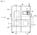
FIG. 2 is a front view of the robot cell inFIG. 1 . -
FIG. 3 illustrates the inside of the robot cell inFIG. 1 viewed from above. -
FIG. 4 illustrates the inside of the robot cell inFIG. 1 viewed from obliquely above. -
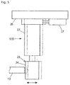
FIG. 5 is a side view illustrating a processing device (precision grinder) arranged inside of the robot cell inFIG. 1 . -
FIG. 6 illustrates the inside of a robot cell according to another embodiment of the present invention viewed from obliquely above. -
FIG. 7 is a front view of a robot hand according to an embodiment of the present invention, illustrating a state of workpiece processing. -
FIG. 8 is a side view of the robot hand inFIG. 7 . -
FIG. 9 is a perspective view illustrating part of the robot hand inFIG. 7 . -
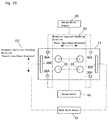
FIG. 10 is a schematic view illustrating part of the robot hand inFIG. 7 to FIG. 9 together with a first drive source, a second drive source, and a vacuum source. -
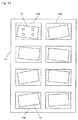
FIG. 11 is a schematic view illustrating the storage condition of a workpiece in a tray. -
FIG. 12 is a front view illustrating the outer spread state in the robot hand inFIG. 7 . -
FIG. 13 is a side view of the robot hand inFIG. 12 . -
FIG. 14 a schematic view illustrating part of the robot hand inFIG. 12 andFIG. 13 together with the first drive source and second drive source. -
FIG. 15 is a front view illustrating the forward-projecting state in the robot hand inFIG. 7 . -
FIG. 16 is a side view of the robot hand inFIG. 15 . -
FIG. 17 is a front view illustrating the positioning state in the robot hand inFIG. 7 . -
FIG. 18 is a side view of the robot hand inFIG. 17 . -
FIG. 19 is a schematic view illustrating part of the robot hand inFIG. 17 andFIG. 18 together with the first drive source and second drive source. -
FIG. 20 is a schematic side view illustrating the workpiece positioning operation in the robot hand inFIG. 7 , showing the forward-projecting state. -
FIG. 21 is a schematic plan view corresponding toFIG. 20 . -
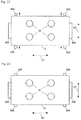
FIG. 22 is a schematic plan view illustrating the state that a short-side positioning abutting piece is moved to the positioning position from the state inFIG. 21 . -
FIG. 23 is a schematic plan view illustrating the state that a long-side positioning abutting piece is moved to the positioning position from the state inFIG. 22 . -
FIG. 24 is a schematic front view illustrating how a sucking pad is deformed in the state inFIG. 23 . -
FIG. 25 is a schematic front view illustrating how the sucking pad is returned to the normal state by supplying vacuum destructing air. -
FIG. 26 is a schematic plan view corresponding toFIG. 25 . -
FIG. 27 is a schematic side view illustrating how the workpiece held by the robot hand inFIG. 27 is ground. -
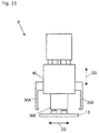
FIG. 28 is a side view illustrating a workpiece reverse support device according to an embodiment of the present invention. -
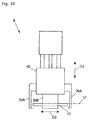
FIG. 29 is a bottom view of the workpiece reverse support device inFIG. 28 . -
FIG. 30 is a system diagram schematically illustrating the workpiece reverse support device inFIG. 28 . -
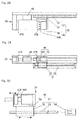
FIG. 31 is a side view illustrating the operation of the workpiece reverse support device inFIG. 28 , showing the state that a fluid pressure cylinder is in a first position. -
FIG. 32 is a side view illustrating the operation of the workpiece reverse support device inFIG. 28 , showing the state that a fluid pressure cylinder is in a second position. -
FIG. 33 is a side view illustrating the operation of the workpiece reverse support device inFIG. 28 , showing a workpiece pinching state. -
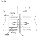
FIG. 34 is a schematic view illustrating how the workpiece held by the workpiece reverse support device inFIG. 28 is reversely held by the robot hand. - Hereunder, a robot cell according to an embodiment of the present invention will be described referring to the figures.
- The robot cell according to the embodiment is to carry out a grinding process on a workpiece. The workpiece to be processed is typically a substantially flat workpiece, a workpiece with a short side wall rising from (part of) a side edge of the flat plate, or the like. Material of the workpiece may be magnetic or non-magnetic, and typically it is a non-magnetic metal such as aluminum alloy or magnesium alloy.
- As illustrated in
FIG. 1 to FIG. 4 , therobot cell 1 comprises acell skeleton 2 generally formed of a rectangular parallelepiped, and thecell skeleton 2 has fourside walls 2A, aceiling 2B arranged to the upper ends of theside walls 2A, and abottom wall 2C arranged to the lower ends of theside walls 2A. - A horizontal work table 3 extending in the horizontal direction is provided in the center portion in the vertical direction inside of the
cell skeleton 1, and awork space 4 is formed above the horizontal work table 3. - A six-axis articulated
robot 5 is arranged inside of therobot cell 1 and suspended from the ceiling. Therobot 5 comprises abase portion 6 fixed to theceiling 2B of thecell skeleton 2, arobot arm 7 whose proximal end portion is connected to thebase portion 6, and arobot hand 8 mounted on a distal end of therobot arm 7. - Plural kinds of
robot hands 8 are previously provided in order to be used for different purposes in accordance to the use, and therobot hand 8 is mounted detachably on the distal end of therobot arm 7. Thenon-used robot hands 8 are placed on a hand placing table 9 (FIG. 4 ). - As illustrated in
FIG. 1 , a tray elevating/loweringdevice control device 11 are arranged below the horizontal work table 3. The robot5, a processing device 12 (FIG. 3 ,FIG. 4 ), the tray elevating/loweringdevice control device 11. - The supply side tray elevating/lowering
device 10A has a supply side elevating/loweringportion 15A which elevates a plurality oftrays 14 each storingworkpieces 13 before processing in order, and the discharge side tray elevating/loweringdevice 10B has a discharge side elevating/loweringportion 15B which lowers a plurality oftrays 14 each storing theworkpieces 13 after processing in order. - A plurality of workpieces 13 (eight pieces in
FIG. 3 ) are stored in onetray 14, and a plurality oftrays 14 are set to the supply side elevating/loweringportion 15A and the discharge side elevating/loweringportion 15B respectively in a state of stacking vertically. - As illustrated in
FIG. 2 , a carry-indoor 16 for carrying thetrays 14 storing theworkpieces 13 before processing into therobot cell 1 and a carry-outdoor 17 for carrying thetrays 14 storing theworkpieces 13 after processing out from the inside of therobot cell 1 are provided in front of thecell skeleton 2. - A pair of
work doors robot cell 1 are provided above the carry-indoor 16 and the carry-outdoor 17 in front of thecell skeleton 2. Anoperation panel 19 of therobot cell 1 is provided to onework door 18A of the pair ofwork doors - As illustrated in
FIG. 3 andFIG. 4 , a plurality of processing devices 12 (12A, 12B, 12C, 12D) for processing theworkpiece 13 in a state of being held by therobot hand 8 are installed in thework space 4 inside of thecell skeleton 2. - Namely, three kinds of belt-
type grinding machines - Here, the grinding belts (processing surfaces) 20A, 20B, 20C of the belt-
type grinding machines workpiece 13 is pressed against. - Also, an
electric precision grinder 12D and a grindingbrush 12E are installed on theside wall 2A of thecell skeleton 2 as other processing devices. The grindingbrush 12E applies grinding processing on theworkpiece 13 by rubbing theworkpiece 13 against its grinding surface (processing surface) 21. - As illustrated in
FIG. 5 , theelectric precision grinder 12D applies grinding processing on theworkpiece 13 by pressing the workpiece 13 against a grinding surface (processing surface) 24 of a rotational grindingmember 23 which is rotationally driven by adrive motor 22. A suction duct 25 (FIG. 4 ) for collecting grinding powder scattering upon grinding processing is installed near theelectric precision grinder 12D. - As illustrated in
FIG. 5 , theelectric precision grinder 12D is movably installed via aLM guide 26 fitted to thecell skeleton 2 and also is elastically movable in the direction that theworkpice 13 is pressed against by anelastically rebounding unit 27 such as an air cylinder. - As illustrated in
FIG. 4 , anair blow nozzle 28 for blowing off the grinding powder adhered to theworkpiece 13 upon grinding processing is installed below theelectric precision grinder 12D and grindingbrush 12E on theside wall 2A of therobot cell 2. - A workpiece
reverse support device 29 for supporting face/back reverse of theworkpiece 13 in therobot hand 8 is installed to theceiling 2B of thecell skeleton 2. The workpiecereverse support device 29 will be described in detail later referring toFIG. 28 to FIG. 34 . - All of the three kinds of belt-
type grinding machines electric precision grinder 12D, grindingbrush 12E,air blow nozzle 28, and workpiecereverse support device 29 are arranged in a region on the rear side of thework space 4 of thecell skeleton 2. - A
supply side opening 30A to which thesupply side tray 14 is arranged and adischarge side opening 30B to which thedischarge side tray 14 is arranged are formed on the front side of the horizontal work table 3. Of the plurality oftrays 14 set to the supply side elevating/loweringportion 15A of the supply side tray elevating/loweringdevice 10A, theuppermost tray 14 is installed in thework space 4 via thesupply side opening 30A. - In contrast, the
discharge side tray 14 for storing the processedworkpiece 13 is arranged in the discharge side elevating/loweringportion 15A of the discharge side tray elevating/loweringdevice 10A in thework space 4 via thedischarge side opening 30B. - By operating the
operation panel 19 inFIG. 2 , press-in amount of theworkpiece 13 to the processing surfaces 20A, 20B, 20C, 21 of theprocessing device 12 by therobot hand 8 can be manually adjusted via thecontrol device 11 inFIG. 1 . In this case, theoperation panel 19 andcontrol device 11 function as the manual adjusting unit in the present invention. - As described above, the
robot cell 1 according to the present embodiment processes theworkpiece 13 in a state of being held by therobot hand 8 by thevarious processing devices 12 installed in the robot cell. Therefore, therobot 5 of therobot cell 1 in the embodiment is required to move more complicatedly compared to the case when a workpiece is simply conveyed by a robot. - Then, in the
robot cell 1 according to the embodiment, thevarious processing devices 12 for processing theworkpiece 13 in the state of being held by therobot hand 8 are installed in thecell skeleton 2 and also therobot 5 is suspended from theceiling 2B of thecell skeleton 2 so as to significantly improve the space efficiency, avoiding that therobot 5 moving complicatedly interferes with instruments/structures around the same. - Also, the processing surfaces (grinding surfaces) 20A, 20B, 20C, 21 of all of the
processing devices 12 used in therobot cell 1 is elastically movable in the pressing direction of theworkpiece 13. Therefore, when setting a pressing operation of theworkpiece 13 by therobot 5, a moving width of the processing surfaces (grinding surfaces) 20A, 20B, 20C, 21 can be used as an allowable error in the robot operation. - As stated above, the moving width of the processing surfaces (grinding surfaces) 20A, 20B, 20C, 21 can be used as the allowable error in the robot operation. It is also effective for realizing a desired processing operation while making the
robot 5 move complicatedly in thelimited work space 4 in therobot cell 1 and avoiding interference with instruments/structures around the same. - Also, as the allowable error to the operation setting of the
robot 5 is ensured as mentioned above, teaching work of the robot operation becomes easy. Therefore, all of the teaching data produced offline can be shared in therobot cell 1 even when a plurality of thesame robot cells 1 are installed. - Thereby, it is enough that a test operation adjustment of the
robot cell 1 is performed before carrying into the spot at the shipping source, for example, and also fine adjustment is performed at the spot while checking an actual operation of therobot 5. The fine adjustment can be performed by a worker at the spot using theoperation panel 19. -
FIG. 6 illustrates a variation of the above-mentionedrobot cell 1, and all of the three kinds of belt-type grinding machines side wall 2A of thecell skeleton 2. Thereby, the grindingsurfaces type grinding machines - As the grinding powder generated in the grinding processing falls down by gravity by orientating the grinding
surfaces type grinding machines type grinding machines - Also, as the
processing device 12 is not on the horizontal work table 3 in the variation illustrated inFIG. 6 , enough work space for performing maintenance work can be secured. - Next, a robot hand according to an embodiment of the present invention will be described referring to
FIG. 7 to FIG. 27 . - The
robot hand 8 according to the embodiment has ahand base portion 31 mounted on a distal end of therobot arm 7, and thehand base portion 31 is provided with aworkpiece holding unit 32 for holding aworkpiece 13 during transfer and processing, as illustrated inFIG. 7 to FIG. 10 . - The
workpiece holding unit 32 has four suckingportions 33 for sucking the surface of theworkpiece 13 so as to releasably hold theworkpiece 13. Each suckingportion 33 is configured to be elastically deformed in a direction parallel to the surface of theworkpiece 13 in the state that theworkpiece 13 is sucked. Preferably, each suckingportion 33 is configured by a bellows-type vacuum sucking pad. - The
robot hand 8 further has aworkpiece positioning unit 34 for positioning theworkpiece 13 held by theworkpiece holding unit 32 to a predetermined position with respect to theworkpiece holding unit 32. Theworkpiece positioning unit 34 has sixpositioning abutting members 35 for abutting on theworkpiece 13 so as to position theworkpiece 13 to a predetermined position. - The
positioning abutting member 35 is composed of three sets of a pair ofpositioning abutting pieces positioning abutting pieces 35A, 36B, two sets of a pair ofpositioning abutting pieces 36A pinch the long-side of theworkpiece 13, and the remaining one set of a pair ofpositioning abutting pieces 36B pinch the short-side of theworkpiece 13. - The pinching direction of the
workpiece 13 by thepositioning abutting piece 36A for the workpiece long-side and the pinching direction of theworkpiece 13 by thepositioning abutting piece 36B for the workpiece short-side are orthogonal to each other. - The width of the
positioning abutting piece 36B for the workpiece short-side is larger than the width of thepositioning abutting piece 36A for the workpiece long-side. - As illustrated in
FIG. 8 andFIG. 9 , a distal end of thepositioning abutting piece 36A protrudes inward. - The
workpiece positioning unit 34 further has a forward/backwardposition switching unit 38 for switching thepositioning abutting pieces workpiece holding surface 37 of theworkpiece holding unit 32 and a backward retracted position retracted backward from theworkpiece holding surface 37. - As illustrated in
FIG. 7 , the forward/backwardposition switching unit 38 has a pair ofair cylinders 39 for forward/backward operation and each abuttingpiece supporting member 40 is provided to a distal end of apiston 39A of eachair cylinder 39 for forward/backward operation. Thepositioning abutting piece 36B for the short-side is fixingly provided to each abuttingpiece supporting member 40. - Each
air cylinder 39 for forward/backward operation is fixingly provided to eachcylinder supporting member 41, and eachcylinder supporting member 41 is supported so as to be moved linearly by afirst LM guide 42 fixingly provided to thehand base portion 31. - Each
cylinder supporting member 41 is driven to be moved linearly in a long-side extending direction (first inner/outer direction) D1 of theworkpiece 13 by afirst drive source 43 illustrated inFIG. 10 . Thereby, the position of the pair ofpositioning abutting pieces 36B for the short-side is switched between a positioning position when positioning theworkpiece 13 in a predetermined position, an outward spread position more outward than the positioning position, and an inward retracted position more inward than the positioning position. - Each
second LM guide 44 is provided to the inner surface of each abuttingpiece supporting member 40, where eachpositioning abutting piece 36A for the workpiece long-side is supported to be moved linearly by eachsecond LM guide 44. The linear motion direction by thesecond LM guide 44 is orthogonal to the linear motion direction by thefirst LM guide 42. - Each
positioning abutting piece 36A for the workpiece long-side is driven to be moved linearly in a short-side extending direction (second inner/outer direction) D2 of the workpiece by asecond drive source 45 inFIG. 10 . Thereby, the position of the pair ofpositioning abutting pieces 36A for the long-side is switched between a positioning position when positioning theworkpiece 13 in a predetermined position, an outward spread position more outward than the positioning position, and an inward retracted position more inward than the positioning position. - By the above-mentioned
first LM guide 42,first drive source 43,second LM guide 44, andsecond drive source 45, theworkpiece positioning unit 34 switching thepositioning abutting pieces workpiece 13 in a predetermined position, an outward spread position more outward than the positioning position, and an inward retracted position more inward than the positioning position is configured. - Here, inward retracted position of the
positioning abutting pieces workpiece 13 held by theworkpiece holding unit 32 in a view from the axis line direction (direction orthogonal to the workpiece surface) of therobot arm 7 as illustrated inFIG. 10 . - The abutting
piece supporting member 40 is moved in a forward/backward direction (arm axis line direction) D3 by the reciprocating operation of thepiston 39A of theair cylinders 39 for forward/backward operation illustrated inFIG. 7 . Thereby, thepositioning abutting piece 36A for the long side and thepositioning abutting piece 36B for the short side are switched between the forward protruding position and the backward retracted position. The forward protruding position and the backward retracted position will be described later referring toFIG. 12 to FIG. 16 . - Each sucking
portion 33 of theworkpiece holding unit 32 is evacuated by avacuum source 46 inFIG. 10 , thereby suckingly holding the surface of theworkpiece 13. When releasing the workpiece 13 from each suckingportion 33, vacuum break air is supplied to each suckingportion 33 so as to release the vacuum state inside of each suckingportion 33, thereby releasing theworkpiece 13. -
FIG. 11 illustrates the state that a plurality of workpieces 13 (eight pieces inFIG. 11 as an example) to be processed in therobot cell 1 are stored in thetray 14. Storing recessedportions 14A for storing theirrespective workpieces 13 are formed in thetray 14 and the inner periphery of each storing recessedportion 14A has a dimension a little larger than the outer periphery of theworkpiece 13. Thereby, a certain clearance is formed between the inner periphery of the storing recessedportion 14A and the outer periphery of theworkpiece 13. - Since there is a clearance between the inner periphery of the storing recessed
portion 14A and the outer periphery of theworkpiece 13 as stated above, the directions of theworkpieces 13 stored in their respective storing recessedportions 14A are inconsistent with each other, as illustrated inFIG. 11 . Therefore, the sucking position on the workpiece surface according to each suckingportion 33 of theworkpiece holding unit 32 of therobot hand 8 cannot be constant in the plurality ofworkpieces 13. - As described above, the
robot cell 1 according to the embodiment processes theworkpiece 13 in a state held by therobot hand 8 by theprocessing device 12 installed thereinside. Therefore, the processing quality by theprocessing device 12 varies or processing of theworkpiece 13 itself becomes impossible unless theworkpiece 13 is precisely positioned in a predetermined position with respect to theworkpiece holding unit 32 of therobot hand 8. - Especially in the grinding processing, the distance between the surface of the
workpiece 13, and the processing surfaces 20A, 20B, 20C, 21 of thegrinding machines electric precision grinder 12D affects the processing quality, and therefore it is extremely important to position theworkpiece 13 to a predetermined position precisely in theworkpiece holding unit 32 of therobot hand 8. - Then, in the
robot hand 8 according to the embodiment, after theworkpiece 13 in the storing recessedportion 14A of thetray 14 is once held by theworkpiece holding unit 32 and taken out, the holding position of theworkpiece 13 is moved and corrected to a predetermined position by using theworkpiece positioning unit 34. - Namely, after the sucking
portion 33 of theworkpiece holding unit 32 is abutting on the workpiece surface as illustrated inFIG. 7 andFIG. 8 and the surface of theworkpiece 13 is suckingly held with the suckingportion 33 using avacuum source 46 inFIG. 10 , theworkpiece 13 is pulled up and taken out from the storing recessedportion 14A of thetray 14. - Note that, although the
positioning abutting pieces workpiece positioning unit 34 need to be in the backward retracted positions as illustrated inFIG. 7 when taking out the workpiece 13 from the storing recessedportion 14A of thetray 14, they do not always need to be in the inward retracted positions and may be in the outward spread position. Namely, it is all right if theworkpiece positioning unit 34 does not interfere with theworkpiece 13 or thetray 14 during the sucking operation of theworkpiece 13 by theworkpiece holding unit 32. - Next, the first drive source and second drive source are operated so that the
positioning abutting piece 36A for the long-side and thepositioning abutting piece 36B for the short-side are moved to the outward spread position as illustrated inFIG. 12 to FIG. 14 . Note that this spread operation is unnecessary when thepositioning abutting piece - Here, the outward spread position of the
positioning abutting piece workpiece 13 held by theworkpiece holding unit 32 in a view from the axis line direction (direction orthogonal to the workpiece surface) of therobot arm 7 as illustrated inFIG. 14 . The outer spread position is set considering the dimension of the gap between the inner periphery of the storing recessedportion 14A of thetray 14 and the outer periphery of theworkpiece 13, namely, the displacement amount of theworkpiece 13 in the storing recessedportion 14A. - Next, as illustrated in
FIG. 15 andFIG. 16 , thepositioning abutting piece 36A for the long-side and thepositioning abutting piece 36B for the short-side in the backward retracted position are advanced to the forward protruding position by driving theair cylinder 39 for forward/backward operation. Thereby, eachpositioning abutting piece workpiece holding surface 37 of theworkpiece holding unit 32. - Next, as illustrated in
FIG. 17 to FIG. 19 , thepositioning abutting piece 36A for the long-side and thepositioning abutting piece 36B for the short-side in the outward spread position are moved to the positioning positions by driving thefirst drive source 43 and thesecond drive source 45. - Specifically, of the
positioning abutting pieces FIG. 20 and FIG. 21 , firstly thepositioning abutting piece 36B for the short-side is moved to the positioning position as illustrated inFIG. 22 by afirst drive source 43. Thereby, theworkpiece 13 is positioned in the workpiece long-side extending direction D1 in a state of being held by theworkpiece holding unit 32. - Next, the
positioning abutting piece 36A for the long-side is moved to the positioning position as illustrated inFIG. 23 by asecond drive unit 45. Thereby, theworkpiece 13 is positioned in the workpiece short-side extending direction D2 in a state of being held by theworkpiece holding unit 32. - By these operations, the
workpiece 13 is positioned to a predetermined position as illustrated inFIG. 23 . At this time, the suckingportion 33 of theworkpiece holding unit 32 is in a deformed shape deviating from a normal shape as illustrated inFIG. 24 . Namely, as the suckingportion 33 is elastically deformable in a direction parallel to the surface of theworkpiece 13, when theworkpiece 13 is moved by thepositioning abutting pieces workpiece 13 as illustrated inFIG. 24 . - In the state in
FIG. 24 , the vacuum destructing air is supplied to each suckingportion 33 instantaneously so as to release the sucking state between each suckingportion 33 and the surface of theworkpiece 13 instantaneously. Then, each suckingportion 33 is returned to the normal shape as illustrated inFIG. 25 and also each suckingportion 33 is moved to a predetermined position on the surface of theworkpiece 13 as illustrated inFIG. 26 and suckingly holds theworkpiece 13 in the predetermined position. - Note that, even when the vacuum destructing air is supplied to each sucking
portion 33 instantaneously, theworkpiece 13 does not drop from therobot hand 8 since it is pinched by thepositioning abutting pieces - Also, even when the
workpiece 13 is pressed and moved when the vacuum destructing air is supplied to the suckingportion 33, since the distal end of thepositioning abutting piece 36A for the workpiece long-side protrudes inward, the protruding portion can receive theworkpiece 13, surely preventing the workpiece 13 from dropping. - After holding the
workpiece 13 in the predetermined position by theworkpiece holding unit 32 according to the operations above, theair cylinder 39 for forward/backward operation is driven so as to retract thepositioning abutting pieces positioning abutting pieces first drive source 43 andsecond drive source 45. -
FIG. 27 illustrates how theworkpiece 13 positioned in the predetermined position according to the above operations is processed by the processing surfaces (grinding surfaces) 20A, 20B, 20C of theprocessing device 12 in the state that theworkpiece 13 is held by theworkpiece holding unit 32 of therobot hand 8. Here, as thepositioning abutting pieces positioning abutting pieces processing device 12 when carring out the grinding process on the side peripheral surface of theworkpiece 13, as illustrated inFIG. 27 . - As stated above, in the
robot hand 8 according to the embodiment, therobot hand 8 itself comprises a function of positioning theworkpiece 13, and therefore a special apparatus does not need to be arranged only for positioning theworkpiece 13 and thelimited work space 4 in therobot cell 1 can be used effectively. - Also, in the
robot hand 8 according to the embodiment, theworkpiece holding unit 32 for sucking the surface of theworkpiece 13 so as to hold the same is used and also thepositioning abutting pieces workpiece 13, and therefore the grinding process on the side peripheral surface of theworkpiece 13, for example, can be performed without any problems. - Next, the workpiece
reverse support device 29 according to an embodiment of the present invention will be described referring toFIG. 28 to FIG. 34 . - As stated above, although the
robot hand 8 sucks the surface of theworkpiece 13 by each suckingportion 33 of theworkpiece holding unit 32 so as to suck theworkpiece 13, sometimes the surface of theworkpiece 13 directed upward in a state of being stored in thetray 14 is processed by theprocessing device 12 depending on the kinds or processing contents of theworkpiece 13. In this case, theworkpiece 13 taken out from thetray 14 by therobot hand 8 needs to be reheld by therobot hand 8 reversing face/back. - The workpiece
reverse support device 29 according to the embodiment is for supporting the face/back reverse of theworkpiece 13 in therobot hand 8 in such a case and preferably installed on theceiling 12B of therobot cell 1 as illustrated inFIG. 4 . - As illustrated in
FIG. 28 (side view) andFIG. 29 (bottom view), the workpiecereverse support device 29 according to the embodiment has a pair ofworkpiece pinching members workpiece 13 held by therobot hand 8 so as to pinch theworkpiece 13. The pair ofworkpiece pinching members workpiece pinching member 47A and a movableworkpiece pinching member 47B, pinching theworkpiece 13 so that theworkpiece 13 is substantially orthogonal to the ceiling surface of therobot cell 1. - A ceiling
side abutting base 48 is provided above theworkpiece 13 pinched by the fixedworkpiece pinching member 47A and the movableworkpiece pinching member 47B. - The workpiece
reverse support device 29 further comprises a workpiece pinchingmember drive unit 49 as illustrated inFIG. 30 , and the workpiece pinchingmember drive unit 49 has afluid pressure cylinder 50 including apiston 50A on which the movableworkpiece pinching member 47B is mounted and acylinder moving unit 51 for moving thefluid pressure cylinder 50 in the reciprocating direction of thepiston 50A. Thefluid pressure cylinder 50 is preferably an air cylinder. - The
cylinder moving unit 51 comprises a travellingmember 52 to which thefluid pressure cylinder 50 is fixingly provided and a travelling member LM guide 53 supporting the travellingmember 52 so that it moves linearly, and adrive source 54 for travelling which drives the travellingmember 52 so that it travels. The position of thefluid pressure cylinder 50 can be switched between the first position inFIG. 31 and the second position inFIG. 32 by thecylinder moving unit 51. - A pinching
state switching member 55 is configured for switching the position of the movableworkpiece pinching member 47B between the position in theworkpiece 13 pinching state and the position in the releasing state by thefluid pressure cylinder 50 and thecylinder moving unit 51. - When reversing the
workpiece 13 face/back in therobot hand 8 using the workpiecereverse support device 29, theworkpiece 13 held by theworkpiece holding unit 32 of therobot hand 8 is abutted on the fixedworkpiece pinching member 47A and the ceilingside abutting base 48 by the operation of therobot 5 as illustrated inFIG. 31 andFIG. 34 in the state that thefluid pressure cylinder 50 is made in the first position inFIG. 31 by thecylinder moving unit 51. - Here, the
workpiece 13 held by theworkpiece holding unit 32 of therobot hand 8 is positioned in a predetermined position relative to theworkpiece holding unit 32 by the above-statedworkpiece positioning unit 34. Therefore, theworkpiece 13 can be accurately positioned to the fixedworkpiece pinching member 47A and the ceilingside abutting base 48 by the operation of therobot 5. - The
fluid pressure cylinder 50 is moved to the second position as illustrated inFIG. 32 by thecylinder moving unit 51 in the state that theworkpiece 13 is abutted on the fixedworkpiece pinching member 47A and the ceilingside abutting base 48 by therobot 5. Subsequently, the movableworkpiece pinching member 47B is advanced by driving thefluid pressure cylinder 50 so as to pinch and hold theworpiece 13 by the fixedworkpiece pinching member 47A and the movableworkpiece pinching member 47B as illustrated inFIG. 33 . - Next, in the state that the holding state of the
workpiece 13 by theworkpiece holding unit 32 of therobot 5 is released and theworkpiece 13 is temporarily held by the workpiecereverse support device 29, the suckingportion 33 of theworkpiece holding unit 32 is abutted on the back surface of theworkpiece 13 so as to suckingly hold theworkpiece 13 by operating therobot 5 as shown with the virtual line inFIG. 34 . - At this time, as the position and direction of the
workpiece 13 held by the workpiecereverse support device 29 are previously acquired accurately, theworkpiece 13 can be held in the predetermined position by theworkpiece holding unit 32 of therobot 6 by operating therobot 5 based on the workpiece position information which has been previously acquired. - Subsequently, the
fluid pressure cylinder 50 and thecylinder moving unit 51 are driven so as to release the workpiece 13 from the fixedworkpiece pinching member 47A and the movableworkpiece pinching member 47B, and therobot 5 is operated so as to take theworkpiece 13 out from the workpiecereverse support device 29. - After that, the
robot 5 processes the workpiece by theprocessing device 12 while three-dimensionally handling theworkpiece 13. - As the workpiece
reverse support device 29 according to the embodiment pinches and holds theworkpiece 13 by the pair ofworkpiece pinching members 47A, 48B as stated above, flexibility of installation state (installation location, installation posture, or the like) of the workpiecereverse support device 29 can be enhanced. - For example, as the workpiece
reverse support device 29 according to the embodiment, the installation location can be the ceiling surface of therobot cell 1, and thereby thelimited work space 4 in therobot cell 1 can be used effectively. - Especially, as a device which requires a relatively large installation area as the belt-
type grinding machines robot cell 1 for implementing grinding process, it is extremely advantageous that the workpiecereverse support device 29 has high flexibility in its installation location for apparatus arrangement design. - Note that it is preferable that the pair of
workpiece pinching members reverse support device 29 pinch the workpiece13 so that therobot 5 is positioned on a pinching direction axis line A1 of the workpiece 13 (seeFIG. 3 ). - The operation of the
robot 5 when therobot 5 have access to the workpiecereverse support device 29 can be symmetric by positioning therobot 5 on the pinching direction axis line A1 of theworkpiece 13. Thereby, the operation space of therobot 5 can be ensured easily even in thelimited work space 4 in therobot cell 1. - Hereunder, an example of the processes of grinding the
workpiece 13 in the above-statedrobot cell 1 will be described. - A worker opens the carry-in door in front of the
cell skeleton 2 and sets a plurality oftrays 14 at vertically spaced intervals to the supply side elevating/loweringportion 15A of the supply side tray elevating/loweringdevice 10A. A plurality ofworkpieces 13 to be processed are placed on eachtray 14. At this time, the supply side elevating/loweringportion 15A is arranged at the lowermost position. - Next, the worker closes the carry-in
door 16, inputs a workpiece type and quantity via theoperation panel 19, and presses the start button. Then, therobot 5 selects therobot hand 8 for a selected workpiece from a plurality ofrobot hands 8 on the hand placing table 9 and chucks the same. - On the other hand, the supply side tray elevating/lowering
device 10A elevates the supply side elevating/loweringportion 15A so as to move theuppermost tray 14 to a predetermined workpiece acquiring position, namely the position of thesupply side opening 30A. - The
robot 5 sucks one of the plurality ofworkpieces 13 stored in thetray 14 on the supply side by the suckingportion 33 of theworkpiece holding unit 32 so as to take the same out, and positions theworkpiece 13 according to the above-stated positioning operation of theworkpiece positioning unit 34. - The
robot 5 conveys theworkpiece 13 held by theworkpiece holding unit 32 of therobot hand 8 to the workpiecereverse support device 29 installed on theceiling 2B of thecell skeleton 2 and makes the workpiecereverse support device 29 hold theworkpiece 13 temporarily. - The
robot 5 abuts the suckingportion 33 of theworkpiece holding unit 32 on the back surface of theworkpiece 13 held by the workpiecereverse support device 29 so as to suck the same. Thereby, theworkpiece 13 is reversed face/back in therobot hand 8 so as to be reheld. - Next, the
robot 5 carries out a predetermined grinding process on theworkpiece 13 using theprocessing device 12 and properly blows the grinding powder adhered on theworkpiece 13 during grinding by the air from theair blow nozzle 28 so as to finish the grinding processing. - The
workpiece 13 which has finished grinding process is conveyed to the workpiecereverse support device 29 by therobot 5 so as to be reversed again. Therobot 5 reholds theworkpiece 13 using the workpiecereverse support device 29, and after that therobot 5 stores theworkpiece 13 in thedischarge side tray 14 placed on the discharge side elevating/loweringportion 15B of the discharge side tray elevating/loweringdevice 10B. - Repeating the above-stated series of operations, for all of the plurality of
workpieces 13 stored in the uppermostsupply side tray 14, their respective grinding processes are carried out. Thetray 14 on the discharge side in which the processedworkpiece 13 is stored is lowered by the discharge side tray elevating/loweringdevice 10B by only one stage. - The
robot 5 suckingly holds the emptysupply side tray 14 by theworkpiece holding unit 32 and places the same on thetray 14 on the discharge side in which the processedworkpieces 13 are stored. The supply side tray elevating/loweringdevice 10A elevates the supply side elevating/loweringportion 15A by only one stage so as to arrange thenext tray 14 in which the plurality ofworkpieces 13 to be processed are stored to a predetermined workpiece acquiring position, namely thesupply side opening 30A formed on the horizontal work table 3. - Repeating the above-stated operations, after finishing the grinding process on the
workpieces 13 in all thetrays 14 set on the supply side elevating/loweringportion 15A, the worker opens the carry-outdoor 17 so as to carry thedischarge side tray 14 out from the inside of therobot cell 1. - According to the operations above, processes , specifically grinding processes on the plurality of
workpieces 13 stored in the plurality oftrays 14 are finished. -
- 1 ... robot cell
- 2 ... cell skelton
- 2A ... side wall of cell skelton
- 2B ... ceiling of cell skelton
- 2C ... bottom wall of cell skelton
- 3 ... horizontal work table
- 4 ... work space
- 5 ... robot
- 6 ... base portion of robot
- 7 ... robot arm
- 8 ... robot hand
- 9 ... hand placing table
- 10A, 10B ... tray elevating/lowering device
- 11 ... control device
- 12 ... processing device
- 12A, 12B, 12C ... belt-type grinding machine
- 12D ... electric precision grinder
- 12E ... grinding brush
- 13 ... workpiece
- 14 ... tray
- 15A, 15B ... elevating portion of tray elevating/lowering device
- 16 ... carry-in door
- 17 ... carry-out door
- 18A, 18B ... work door
- 19 ... operation panel
- 20A, 20B, 20C ... grinding belt (processing surface)
- 21 ... grinding surface (processing surface) of grinding brush
- 22 ... drive motor
- 23 ... rotational grinding member
- 24 ... grinding surface (processing surface) of rotational grinding member
- 25 ... suction duct for electric precision grinder
- 26 ... LM guide for electric precision grinder
- 27 ... rebounding unit for electric precision grinder (air cylinder)
- 28 ... air blow nozzle
- 29 ... workpiece reverse support device
- 30A ... supply side opening
- 30B ... discharge side opening
- 31 ... hand base portion
- 32 ... workpiece holding unit
- 33 ... sucking portion
- 34 ... workpiece positioning unit
- 35 ... positioning abutting member
- 36A ... positioning abutting piece for long-side
- 36B ... positioning abutting piece for short-side
- 37 ... workpiece holding surface
- 38 ... forward/backward position switching unit
- 39 ... air cylinder for forward/backward operation
- 39A ... piston of air cylinder for forward/backward operation
- 40 ... abutting piece supporting member
- 41 ... cylinder supporting member
- 42 ... first LM guide
- 43 ... first drive source
- 44 ... second LM guide
- 45 ... second drive source
- 46 ... vacuum source
- 47, 47B ... workpiece pinching member
- 48 ... ceiling side abutting base
- 49 ... workpiece pinching member drive unit
- 50 ... fluid pressure cylinder
- 50A ... piston of fluid pressure cylinder
- 51 ... cylinder moving unit
- 52 ... travelling member of cylinder moving unit
- 53 ... LM guide of cylinder moving unit
- 54 ... drive source for travelling of cylinder moving unit
- 55 ... pinching state switching unit
- A1 ... workpiece pinching direction axis line of workpiece reverse support device
- D1 ... workpiece long side extending direction (first inner/outer direction)
- D2 ... workpiece short side extending direction (second inner/outer direction)
- D3 ... forward/backward direction
Claims (9)
- A workpiece reverse support device for supporting a face/back reverse of a workpiece in a robot hand, comprising:a pair of workpiece pinching members for abutting on their respective opposing side portions of the workpiece held by the robot hand so as to pinch the workpiece; anda pinching state switching unit for switching the pair of workpiece pinching members between a pinching state of pinching the workpiece and a releasing state of releasing the workpiece.
- The workpiece reverse support device according to claim 1, wherein the workpiece reverse support device is installed inside of a robot cell in which a robot having the robot hand is arranged.
- The workpiece reverse support device according to claim 2, wherein the pair of workpiece pinching members pinch the workpiece so that the workpiece is substantially orthogonal to any one of inner wall surfaces of the robot cell.
- The workpiece reverse support device according to claim 3, wherein the pair of workpiece pinching members pinch the workpiece so that the workpiece is substantially orthogonal to a ceiling surface of the robot cell.
- The workpiece reverse support device according to any one of claims 2 to 4, wherein the pair of workpiece pinching members are installed on the ceiling surface of the robot cell.
- The workpiece reverse support device according to any one of claims 1 to 5, wherein the pair of workpiece pinching members pinch the workpiece so that the robot is positioned on a pinching direction axis line of the workpiece.
- The workpiece reverse support device according to any one of claims 1 to 6, wherein the pair of workpiece pinching members have a fixed workpiece pinching member and a movable workpiece pinching member, the pinching state switching unit switching a position of the movable workpiece pinching member between a position in the pinching state and a osition in the releasing state.
- The workpiece reverse support device according to claim 7, wherein the pinching state switching unit has a fluid pressure cylinder including a piston on which the movable workpiece pinching member is mounted and a cylinder moving unit for moving the fluid pressure cylinder in areciprocating direction of the piston.
- A robot cell for processing a workpiece, comprising:the workpiece reverse support device according to any one of claims 1 to 8; anda cell skeleton inside which the workpiece reverse support device is installed.
Applications Claiming Priority (2)
| Application Number | Priority Date | Filing Date | Title |
|---|---|---|---|
| JP2013254774A JP6366932B2 (en) | 2013-12-10 | 2013-12-10 | Work reversal support device and robot cell equipped with the same |
| PCT/JP2014/082501 WO2015087855A1 (en) | 2013-12-10 | 2014-12-09 | Workpiece-flipping assistance device and robot cell equipped with said device |
Publications (2)
| Publication Number | Publication Date |
|---|---|
| EP3081344A1 true EP3081344A1 (en) | 2016-10-19 |
| EP3081344A4 EP3081344A4 (en) | 2018-02-14 |
Family
ID=53371158
Family Applications (1)
| Application Number | Title | Priority Date | Filing Date |
|---|---|---|---|
| EP14870400.0A Withdrawn EP3081344A4 (en) | 2013-12-10 | 2014-12-09 | Workpiece-flipping assistance device and robot cell equipped with said device |
Country Status (6)
| Country | Link |
|---|---|
| US (1) | US10265864B2 (en) |
| EP (1) | EP3081344A4 (en) |
| JP (1) | JP6366932B2 (en) |
| KR (1) | KR101873664B1 (en) |
| CN (1) | CN106061687B (en) |
| WO (1) | WO2015087855A1 (en) |
Cited By (1)
| Publication number | Priority date | Publication date | Assignee | Title |
|---|---|---|---|---|
| CN110883655A (en) * | 2019-12-08 | 2020-03-17 | 江西新森岱塑木科技有限公司 | Portable plastic-wood sander |
Families Citing this family (6)
| Publication number | Priority date | Publication date | Assignee | Title |
|---|---|---|---|---|
| JP2016190296A (en) * | 2015-03-31 | 2016-11-10 | セイコーエプソン株式会社 | Robot system |
| CN105500189A (en) * | 2015-11-26 | 2016-04-20 | 重庆耀勇减震器有限公司 | Supporting rod of transmission rack |
| CN106112939A (en) * | 2016-08-25 | 2016-11-16 | 陈红玲 | Electronic wallboard upset car clamping turning device |
| CN110461552B (en) * | 2017-04-03 | 2023-05-23 | 索尼公司 | Manipulator device, production device and production method for electronic equipment |
| WO2023172252A1 (en) * | 2022-03-08 | 2023-09-14 | Path Robotics, Inc. | Manufacturing cells having modular support platforms |
| CN119609744A (en) * | 2024-12-25 | 2025-03-14 | 湖南严格智能技术有限公司 | Automatic feeding and discharging paw device of machine tool and use method |
Family Cites Families (32)
| Publication number | Priority date | Publication date | Assignee | Title |
|---|---|---|---|---|
| GB966609A (en) * | 1965-03-10 | 1900-01-01 | ||
| US4648783A (en) * | 1984-11-06 | 1987-03-10 | Patrick Tan | Educational and laboratory work cell for a robotic device |
| JPS61214983A (en) * | 1985-03-15 | 1986-09-24 | 三菱電機株式会社 | Conveyor for industrial robot |
| JPH03184796A (en) * | 1987-11-06 | 1991-08-12 | Shimadzu Corp | Conveyor system |
| US5132914A (en) * | 1988-04-01 | 1992-07-21 | Restaurant Technology, Inc. | Food preparation system and method |
| US5518542A (en) * | 1993-11-05 | 1996-05-21 | Tokyo Electron Limited | Double-sided substrate cleaning apparatus |
| JPH0929679A (en) * | 1995-07-17 | 1997-02-04 | Ishikawajima Shibaura Mach Co Ltd | Clamping device |
| JPH1190803A (en) | 1997-09-11 | 1999-04-06 | Speedfam Co Ltd | Mirror polishing machine for work edge |
| JP3586623B2 (en) * | 2000-06-23 | 2004-11-10 | ファナック株式会社 | Work exchange device and work handling system |
| FR2811973A1 (en) * | 2000-07-18 | 2002-01-25 | Windmoeller & Hoelscher | Crane gear for transporting e.g. web rolls, paper rolls, has hooks provided at tips of legs and which secure support rod extending through passage hole of e.g. web roll |
| JP3514732B2 (en) * | 2001-01-17 | 2004-03-31 | 川崎重工業株式会社 | Rotary drive |
| US6859683B2 (en) * | 2001-06-04 | 2005-02-22 | Futaba Corporation Of America | Integrated robotic cell |
| US6678583B2 (en) * | 2001-08-06 | 2004-01-13 | Seminet, Inc. | Robotic storage buffer system for substrate carrier pods |
| DK1513749T3 (en) * | 2002-06-06 | 2006-10-09 | Flexfactory Ag | Delivery of shaking parts |
| JP2007021634A (en) * | 2005-07-14 | 2007-02-01 | Komatsu Engineering Corp | Automatic machining method for workpiece and automatic machining system for workpiece |
| KR20070045534A (en) | 2005-10-27 | 2007-05-02 | 엘지.필립스 엘시디 주식회사 | Repair equipment for liquid crystal display device with reversal function and substrate reversal method thereof |
| JP5004612B2 (en) * | 2007-02-15 | 2012-08-22 | 大日本スクリーン製造株式会社 | Substrate processing equipment |
| JP2008213130A (en) * | 2007-03-07 | 2008-09-18 | Seiko Epson Corp | General-purpose cell for production system and production system using the general-purpose cell |
| US8025277B2 (en) * | 2008-02-06 | 2011-09-27 | GM Global Technology Operations LLC | Reconfigurable end-of-arm tool for robotic arm |
| US8263451B2 (en) * | 2010-02-26 | 2012-09-11 | Taiwan Semiconductor Manufacturing Company, Ltd. | Epitaxy profile engineering for FinFETs |
| CH703288B1 (en) * | 2010-06-11 | 2015-02-27 | Robotic Consulting S R L | Method and automatic loading device for flat workpieces in a workpiece processing machine feeder plates, including envelopes. |
| JP5755038B2 (en) * | 2010-06-28 | 2015-07-29 | キヤノン株式会社 | Assembly equipment and production system |
| DE102010060526A1 (en) * | 2010-11-12 | 2012-05-16 | Christian Hieronimi | System for determining and / or controlling objects |
| JP5708196B2 (en) * | 2011-04-21 | 2015-04-30 | セイコーエプソン株式会社 | Collision detection system, robot system, collision detection method and program |
| JP5454524B2 (en) * | 2011-07-15 | 2014-03-26 | 株式会社安川電機 | Parallel link robot and picking system |
| JP2014522659A (en) * | 2011-07-25 | 2014-09-08 | イー・アイ・デュポン・ドウ・ヌムール・アンド・カンパニー | Nucleic acid amplification method for producing fluorescently labeled fragments of stored products and optional products |
| KR101391509B1 (en) * | 2012-08-27 | 2014-05-07 | 한국수력원자력 주식회사 | Remote attaching and detaching device including cell camera |
| JP5737310B2 (en) * | 2013-03-14 | 2015-06-17 | 株式会社安川電機 | Production system, robot cell apparatus, and product production method |
| JP5678979B2 (en) * | 2013-03-15 | 2015-03-04 | 株式会社安川電機 | Robot system, calibration method, and workpiece manufacturing method |
| JP6383537B2 (en) * | 2013-12-10 | 2018-08-29 | 川崎重工業株式会社 | Robot hand, robot, and robot cell |
| JP6397185B2 (en) * | 2013-12-10 | 2018-09-26 | 川崎重工業株式会社 | Robot cell |
| CN106078675A (en) * | 2015-04-28 | 2016-11-09 | 精工爱普生株式会社 | Robot |
-
2013
- 2013-12-10 JP JP2013254774A patent/JP6366932B2/en not_active Expired - Fee Related
-
2014
- 2014-12-09 KR KR1020167018487A patent/KR101873664B1/en not_active Expired - Fee Related
- 2014-12-09 EP EP14870400.0A patent/EP3081344A4/en not_active Withdrawn
- 2014-12-09 US US15/103,537 patent/US10265864B2/en not_active Expired - Fee Related
- 2014-12-09 WO PCT/JP2014/082501 patent/WO2015087855A1/en not_active Ceased
- 2014-12-09 CN CN201480067393.6A patent/CN106061687B/en not_active Expired - Fee Related
Cited By (2)
| Publication number | Priority date | Publication date | Assignee | Title |
|---|---|---|---|---|
| CN110883655A (en) * | 2019-12-08 | 2020-03-17 | 江西新森岱塑木科技有限公司 | Portable plastic-wood sander |
| CN110883655B (en) * | 2019-12-08 | 2021-05-07 | 江西新森岱塑木科技有限公司 | A portable plastic wood sander |
Also Published As
| Publication number | Publication date |
|---|---|
| JP2015112657A (en) | 2015-06-22 |
| CN106061687A (en) | 2016-10-26 |
| US20160318191A1 (en) | 2016-11-03 |
| EP3081344A4 (en) | 2018-02-14 |
| CN106061687B (en) | 2019-08-16 |
| KR101873664B1 (en) | 2018-07-02 |
| KR20160119066A (en) | 2016-10-12 |
| JP6366932B2 (en) | 2018-08-01 |
| WO2015087855A1 (en) | 2015-06-18 |
| US10265864B2 (en) | 2019-04-23 |
Similar Documents
| Publication | Publication Date | Title |
|---|---|---|
| EP3081352A1 (en) | Robot cell | |
| EP3081348A1 (en) | Robot hand, robot, and robot cell | |
| US10265864B2 (en) | Workpiece reverse support device and robot cell including the same device | |
| CN109843503B (en) | Conveying equipment, control device thereof and loading and unloading method of material processing unit | |
| CN106232292A (en) | Robotic unit for loading and unloading during production of single-station machining machines | |
| KR20120007849U (en) | Machining apparatus of plate | |
| KR102459650B1 (en) | Robot-automated machine tool, robot handler used to machine tool and control method for the same | |
| WO2021044620A1 (en) | Automatic backup pin arrangement system for component mounting machine | |
| CN112338618A (en) | Wheel type conversion feeding and discharging device and numerical control machine tool | |
| CN116061044A (en) | Lens preform finish grinding process | |
| CN210235428U (en) | Box positioning device and packaging equipment | |
| JP5923278B2 (en) | Method and apparatus for sucking and transporting cut product | |
| CN107889444B (en) | Component mounting device and component mounting method | |
| JP2022016786A (en) | Manufacture method of work posture changing tool, work posture changing device, and packing body | |
| US10668584B2 (en) | Component mounting method | |
| CN114585478B (en) | Processing system | |
| CN220761388U (en) | Full-automatic glass laser micropore processing device | |
| CN212449706U (en) | Automatic unstacking and stacking robot unit for material boxes | |
| CN204471123U (en) | Workpiece end face processing unit (plant) | |
| JPH09327733A (en) | Working method and equipment | |
| JPH01299724A (en) | Automatic conveyor | |
| JP2014103356A (en) | Processing equipment |
Legal Events
| Date | Code | Title | Description |
|---|---|---|---|
| PUAI | Public reference made under article 153(3) epc to a published international application that has entered the european phase |
Free format text: ORIGINAL CODE: 0009012 |
|
| 17P | Request for examination filed |
Effective date: 20160621 |
|
| AK | Designated contracting states |
Kind code of ref document: A1 Designated state(s): AL AT BE BG CH CY CZ DE DK EE ES FI FR GB GR HR HU IE IS IT LI LT LU LV MC MK MT NL NO PL PT RO RS SE SI SK SM TR |
|
| AX | Request for extension of the european patent |
Extension state: BA ME |
|
| DAX | Request for extension of the european patent (deleted) | ||
| A4 | Supplementary search report drawn up and despatched |
Effective date: 20180115 |
|
| RIC1 | Information provided on ipc code assigned before grant |
Ipc: B25J 9/00 20060101ALI20180109BHEP Ipc: B25J 15/06 20060101ALI20180109BHEP Ipc: B25J 21/00 20060101ALI20180109BHEP Ipc: B25J 15/02 20060101ALI20180109BHEP Ipc: B24B 41/00 20060101ALI20180109BHEP Ipc: B24B 21/00 20060101ALI20180109BHEP Ipc: B23Q 37/00 20060101ALI20180109BHEP Ipc: B25J 9/16 20060101AFI20180109BHEP Ipc: B23Q 7/00 20060101ALI20180109BHEP |
|
| RIC1 | Information provided on ipc code assigned before grant |
Ipc: B25J 9/16 20060101AFI20201016BHEP Ipc: B23Q 37/00 20060101ALI20201016BHEP Ipc: B23Q 7/00 20060101ALI20201016BHEP Ipc: B25J 9/00 20060101ALI20201016BHEP Ipc: B25J 15/06 20060101ALI20201016BHEP Ipc: B25J 21/00 20060101ALI20201016BHEP Ipc: B25J 15/02 20060101ALI20201016BHEP Ipc: B24B 41/00 20060101ALI20201016BHEP Ipc: B24B 21/00 20060101ALI20201016BHEP |
|
| GRAP | Despatch of communication of intention to grant a patent |
Free format text: ORIGINAL CODE: EPIDOSNIGR1 |
|
| RAP1 | Party data changed (applicant data changed or rights of an application transferred) |
Owner name: KAWASAKI JUKOGYO KABUSHIKI KAISHA |
|
| RIN1 | Information on inventor provided before grant (corrected) |
Inventor name: IWASAKI, YUKIO Inventor name: BANDO, KENJI Inventor name: YOSHIMURA, TAKAYUKI Inventor name: MURAKAMI, JUNICHI Inventor name: KURAOKA, SHUHEI |
|
| STAA | Information on the status of an ep patent application or granted ep patent |
Free format text: STATUS: GRANT OF PATENT IS INTENDED |
|
| INTG | Intention to grant announced |
Effective date: 20201203 |
|
| STAA | Information on the status of an ep patent application or granted ep patent |
Free format text: STATUS: THE APPLICATION IS DEEMED TO BE WITHDRAWN |
|
| 18D | Application deemed to be withdrawn |
Effective date: 20210414 |