EP3081266B1 - Flame arrestor - Google Patents
Flame arrestor Download PDFInfo
- Publication number
- EP3081266B1 EP3081266B1 EP16165224.3A EP16165224A EP3081266B1 EP 3081266 B1 EP3081266 B1 EP 3081266B1 EP 16165224 A EP16165224 A EP 16165224A EP 3081266 B1 EP3081266 B1 EP 3081266B1
- Authority
- EP
- European Patent Office
- Prior art keywords
- flame
- flame arrestor
- arrestor
- path
- collar
- Prior art date
- Legal status (The legal status is an assumption and is not a legal conclusion. Google has not performed a legal analysis and makes no representation as to the accuracy of the status listed.)
- Active
Links
Images











Classifications
-
- F—MECHANICAL ENGINEERING; LIGHTING; HEATING; WEAPONS; BLASTING
- F23—COMBUSTION APPARATUS; COMBUSTION PROCESSES
- F23D—BURNERS
- F23D14/00—Burners for combustion of a gas, e.g. of a gas stored under pressure as a liquid
- F23D14/46—Details
- F23D14/72—Safety devices, e.g. operative in case of failure of gas supply
- F23D14/82—Preventing flashback or blowback
- F23D14/825—Preventing flashback or blowback using valves
-
- A—HUMAN NECESSITIES
- A62—LIFE-SAVING; FIRE-FIGHTING
- A62C—FIRE-FIGHTING
- A62C4/00—Flame traps allowing passage of gas but not of flame or explosion wave
-
- A—HUMAN NECESSITIES
- A62—LIFE-SAVING; FIRE-FIGHTING
- A62C—FIRE-FIGHTING
- A62C4/00—Flame traps allowing passage of gas but not of flame or explosion wave
- A62C4/02—Flame traps allowing passage of gas but not of flame or explosion wave in gas-pipes
-
- F—MECHANICAL ENGINEERING; LIGHTING; HEATING; WEAPONS; BLASTING
- F23—COMBUSTION APPARATUS; COMBUSTION PROCESSES
- F23D—BURNERS
- F23D14/00—Burners for combustion of a gas, e.g. of a gas stored under pressure as a liquid
- F23D14/46—Details
- F23D14/72—Safety devices, e.g. operative in case of failure of gas supply
- F23D14/82—Preventing flashback or blowback
-
- A—HUMAN NECESSITIES
- A62—LIFE-SAVING; FIRE-FIGHTING
- A62C—FIRE-FIGHTING
- A62C3/00—Fire prevention, containment or extinguishing specially adapted for particular objects or places
- A62C3/07—Fire prevention, containment or extinguishing specially adapted for particular objects or places in vehicles, e.g. in road vehicles
- A62C3/08—Fire prevention, containment or extinguishing specially adapted for particular objects or places in vehicles, e.g. in road vehicles in aircraft
Definitions
- the present disclosure relates generally to flame arrestors, including modular flame arrestors that may include venting and/or draining capability, and that may be used in a wide range of applications, including aerospace applications.
- Flame arrestors have been used to prevent explosions from propagating inside or outside of an environment or enclosure. Flame arrestors can be used to help extinguish a flame, for instance, by decreasing the temperature of burning gases below an ignition point. That can be accomplished, for example, by (a) employing a longer flame path between an internal volume and an external environment, or (b) including a multitude of very small cross-sectional area flow paths, with the objective of transferring the heat from the burning gas to the flame arrestor and other components. Most existing flame arrestors are designed for large industrial fuel tanks or pipes. Such flame arrestors may address similar, but not identical needs, with respect to aerospace applications and needs, especially with respect to size and weight considerations. That is, with many aerospace applications, the enclosed empty volume will be intentionally minimized by design.
- a flame arrestor is employed to help prevent an internal flame from propagating outside the enclosure.
- conventional aerospace flame arrestors a long flame path is often used. That is, conventional aerospace designs are commonly based on a labyrinth flame path concept involving a series of cross-drilled holes.
- long flame paths can involve or result in, inter alia, a large and heavy device, large pressure drops, and very small flow cross-section areas can restrict draining capability and/or may be susceptible to plugging (e.g., from fouling and icing).
- US 4 072 799 A there is disclosed a flame arrestor as it is defined in the pre-characterizing portion of claim 1.
- the present invention is a flame arrestor as it is defined in claim 1.
- the flame arrestor includes a flame arrestor collar and a flame arrestor plug.
- the collar is configured to connect the flame arrestor to a portion of an enclosure.
- the collar has one or more flame paths in the form of grooves formed in a radially expanded portion of the collar.
- the plug is configured to be inserted into and connected to the collar.
- the plug has a substantially vertical path in an insertion direction in which the plug is insertable into the collar and through which gas is flowable from the enclosure into the flame arrestor, radial paths extending radially outward from the substantially vertical path and in communication with the first side of the one or more flame paths such that the gas exits the radial paths into the one or more flame paths, and one or more exit apertures in a radially expanded portion of the plug and in communication with the second side of the one or more flame paths such that the gas exits the one or more flame paths into the one or more exit apertures and configured to allow the gas to exit the flame arrestor.
- the one or more flame paths includes a spiral or helical flame path which is provided within a radially expanded portion of the collar. Further embodiments of the flame arrestor are defined in the dependent claims.
- the flame arrestor may include a collar that is configured for threaded connection with the plug.
- the flame arrestor may include a plurality of flame path modules or stages.
- the one or more of the plurality of flame path modules or stages may include an aperture configured to transfer gas to another module or stage.
- Each of the flame path modules or stages may include one or more grooves configured to transfer gas from a first side of the flame path to a second side of the flame path.
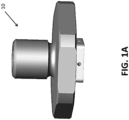
- FIG. 1A generally illustrates an embodiment of a flame arrestor 10 according to aspects of the present disclosure.
- FIG. 1B generally illustrates a cross-sectional view of the flame arrestor 10 shown in FIG. 1A .
- the flame arrestor 10 may include a flame arrestor collar (or collar) 20 and a flame arrestor plug (or plug) 30, which are generally illustrated in FIGS. 1A and 1B in an assembled configuration.
- FIG. 2 generally illustrates how a plug 30 may be connected to a collar 20, such as via a threaded connection.
- flame arrestors may be configured to confine or maintain an internal explosion and may provide a means to drain fluid while stopping a flame from exiting the flame arrestor.
- a flame arrestor 10 may be referred to as a "single-stage flame arrestor” or a “single-stage plane disk flame arrestor.”
- the flame arrestor 10 may connect to or engage with an enclosure, which is generically shown in FIG. 1B for positional environmental purposes only, as enclosure E.
- enclosure E an enclosure
- a portion of the flame arrestor 10 may be configured for a suitably solid or firm engagement with a portion of enclosure E.
- a portion of collar 20 may be configured for a threaded engagement with a portion of an enclosure E. Male threading may be provided on the collar 20 and female threading may be provided in the enclosure E, or vice versa.
- a gas from an enclosure may enter the flame arrestor 10 and flow downwardly through a one or more openings and/or holes disposed on the collar 20.
- the gas may flow downwardly through a first substantially vertical path (e.g., path 32) associated with the one or more openings.
- the gases may generally flow in depicted direction P 1 .
- Path 32 may eventually encounter and/or flow into, one or more connected paths.
- gases flowing from path 32 may flow into depicted radial paths 34a, 34b, with the flow of gases then generally flowing in depicted directions P 2 and P 3 .
- a "spiral" or “helical” flame path may be provided in a radially expanded portion of collar 20.
- the gases entering the flame path may move from an inner diameter to an outer diameter and rotate to holes provided at or about the outer diameter.
- the "spiral" configuration can extend, and/or optimize or maximize, the flame path associated with the flame arrestor 10 to, inter alia, serve to cool gases that may enter the flame path.
- the ratio of flame path length to the cross section diameter may vary by portion or segment.
- the ratio of flame path length to the cross section diameter may be about 50:1 at an input portion, may be about 60:1 through the grooves, and may be about 70:1 at an output portion.
- the concept is not limited to the forgoing specific ratios and/or variations, and the ratio might, for example and without limitation, be about 200:1 for a harsh environment and may be about 10:1 for a gentle environment.
- the flame path(s) provided in collar 20 may interface or interconnect with one or more exit paths - e.g., exit paths 36a, 36b provided in plug 30, which may comprise holes or apertures provided in plug 30.
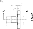
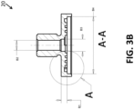
- FIGS. 3A through 3D generally illustrate an exemplary embodiment of a spiral pathtype flame arrestor collar 20. While a number or details and/or dimensions may be included with FIGS. 3A to 3D to help teach concepts, the present disclosure is not limited to such specifics, and those of skill in the art will understand that various other specific sizes, shapes, dimensions, and path configurations may be employed within the scope of the disclosed concepts For example and without limitation, and as generally illustrated in FIG.
- an embodiment of a collar 20 may include dimensions A1, which may be about 1.270 cm (0.500 inches); A2, which may be about 1.067 cm (0.420 inches); A3, which may be about 2.54 mm (0.10 inches); A4, which may be about 1.372 cm (0.540 inches); and A5, which may be about 5.842 mm (0.230 inches). Also, for example and without limitation, and as generally illustrated in FIG.
- a cross-sectional view of an embodiment of the collar 20 may include dimensions B1, which may be about 3.302 mm (0.130 inches); B2, which may be about 6.350 mm (0.250 inches); B3, which may be about 6,858 mm (0.270 inches); and B4, which may be between 3.188 cm (1.255 inches) and 3.195 cm (1.258 inches).
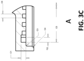
- FIG. 3C illustrates an enlarged detailed view of a portion of the collar 20 depicted in FIG. 3B .
- the portion of the collar 20 may, for example and without limitation, include dimension C1, which may range between 1.448 mm (0.057 inches) and 1.702 mm (0.067 inches); C2, which may range between 1.448 mm (0.057 inches) and 1.702 mm (0.067 inches); C3, which range between 0.254 mm (0.010 inches) and 0.508 mm ( 0.020 inches); C4, which may range between 0.381 mm (0.015 inches) at about 40° and 0.635 mm (0.025 inches) at about 50°; C5, which may range between 2.934 cm (1.155 inches) and 2.959 cm (1.165 inches); and C6, which may range between 1.143 mm (0.045 inches) and 1.397 mm (0.055 inches).
- the spiral groove as generally illustrated in FIG. 3C , may be +/- 2.54 mm (0.100 inches) and a pitch break edge may be +/- 0.127 mm (0.005 inches).
- FIG. 3D generally illustrates a spiral groove wall configuration that forms a spiral flame path.
- the spiral flame path may, for example and without limitation, include dimensions D1, which may be about 3.810 cm (1.500 inches), and D2, which may range between 3.467 cm (1.365 inches) and 3.495 cm (1.376 inches).
- the cross sections may be circular, but it may be simpler to manufacture square cross sections, which may closely emulate the function of circular cross sections.
- the grooves employed in the various embodiments may serve, inter alia, as a collector.
- portions of the spiral groove wall, such as shown in FIG. 3D may be ground to insure a minimum wall thickness - for example and without limitation, a thickness of about 0.762 mm (0.030 inches).
- multiple (or alternate) flame paths may be included to provide alternative paths - which can help prevent blockage. For example, with the inclusion of multiple flame paths, if one flame path is blocked by debris, dust, grease, dirt, etc., another flame path or flame paths may remain functional.
- FIGS. 4A through 4C generally illustrate an exemplary embodiment of a spiral pathtype flame arrestor plug 30. While a number or details and/or dimensions may be included with FIGS. 4A to 4C or other figures herein to help teach concepts, the present disclosure is not limited to such specifics, and those of skill in the art will understand that various other specific sizes, shapes, dimensions, and path configurations may be employed within the scope of the disclosed concepts.
- FIG. 4A illustrates a cross-sectional view of an embodiment of a plug 30, as generally shown in FIG. 4B .
- the plug 30 may, for example and without limitation, include dimension E1, which may be about 6.350 mm (0.250 inches); E2, which may range between 5.953 cm (0.195 inches) and 5.207 mm (0.205 inches); E3, which may be about 1.702 cm (0.670 inches); E4, which may be about 1.270 cm (0.500 inches); E5, which may range between 1.143 mm (0.045 inches) and 1.397 mm (0.055 inches); E6, which may be about 0.762 mm (0.030 inches); and E7, which may range between 3.167 cm (1.247 inches) and 3.175 cm (1.250 inches).
- FIG. 4B generally illustrates a cross-sectional view of the plug 30 as generally shown in FIG. 4A .
- the plug 30 may, for example and without limitation, include dimension F1, which may range between 1.143 mm (0.045 inches) and 1.397 mm (0.055 inches); F2, which may represent a length of an aperture disposed within the collar, and may range between 1.867 cm (0.735 inches) and 1.892 cm (0.745 inches); F3, which may, for example, be associated with four equidistantly-spaced holes, having a diameter of between 1.448 mm (0.057 inches) and 1.702 mm (0.067 inches); F4, which may be about 1.270 mm (0.050 inches); F5, which may be about 1.524 mm (0.060 inches); F6, which may be about 3.048 mm (0.120 inches); F7, which may be about 1.981 cm (0.780 inches); F8, which may range between 0.254 mm (0.010 inches) at about 40° and 0.762 mm (0.030 inches) at about 50°; and F9, which may be about 2.794 cm (1.100 inches).
- F1 may range between 1.143
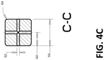
- FIG. 4C generally illustrates a cross-sectional bottom plan view of a portion of the flame arrestor plug 30, such as generally illustrated in FIG. 4B .
- the plug 30 may, for example and without limitation, include dimension G1, which may range between 1.143 mm (0.045 inches) and 1.397 mm (0.055 inches); G2, which may be about 6.299 mm (0.248 inches); G3, which may range between 1.245 cm (0.490 inches) and 1.275 cm (0.502 inches); and G4, which may be about 1.270 mm (0.05 inches).
- FIG. 5 generally illustrates an embodiment of a single-stage flame arrestor 10 shown in an assembled condition and connected to a component.
- an outer hex - which may be turned by a wrench - may be used to lock the parts together.
- FIG. 6 generally illustrates the flame arrestor of FIG. 5 , but with the plug 30 shown removed, which better demonstrates an instance of a spiral or helical flame path.
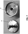
- Embodiments of a collar 20 and a plug 30 are separately and generally illustrated in FIG. 7 .
- FIG. 8A generally illustrates another embodiment of a flame arrestor 10 according to aspects of the present disclosure.
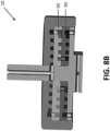
- FIG. 8B generally depicts a cross-sectional view of the flame arrestor 10 shown in FIG. 8A .
- the illustrated embodiment of the flame arrestor 10 shown in FIGS. 8A and 8B may be referred to as a "multiple-stage flame arrestor.”
- This particular embodiment may also employ a spiral or helical flame path configuration.
- a flame path e.g., a spiral or helical flame path
- the number of modules (such as module(s) 50) may be can be adjusted (e.g., increased or decreased) to achieve a designed or desired flame path for a given design envelope and weight.
- all grooves may start from a common, typically circular, collector groove, and may end in a common, typically circular, collector groove.
- the passage between adjacent modules may comprise passages (e.g., holes or apertures) through the inner or outer collector groove, as needed or desired.
- the radially outer diameter of a flame path in a first (e.g., top) module or stage may have holes that are configured to transfer gas to corresponding holes associated with an inner radial diameter of a next (e.g., bottom or lower) module or stage. In this manner, the modules 50 may be configured to allow gas to flow from a first side of a flame path to a second side of a flame path.
- the modules 50 may be configured to allow gas to flow from an entry side of a flame path (e.g., a first side and/or a side gas enters the flame path) to an exit side of the flame path (e.g., a second side and/or a side gas exits the flame path).
- the shape (e.g., cross-sectional shape) of the groove or path may be intentionally or arbitrarily selected, may be round or square or other suitable shape, and may be manufactured on one or both sides of the module.
- Various manufacturing processes can be used to create the groove(s). For example and without limitation, machining, use of a spiral or helical coil wire between plates, etc.
- Embodiments of the disclosed concept which may increase the length of a flame path, may provide for a drop in temperature without causing a substantial pressure drop and/or may provide a reduction in space and weight. Reducing or minimizing pressure drop can be significant because with a long groove if there is a very large pressure drop the release will not be very fast.
- a minimized gap may, for example and without limitation, be about 0.127 mm (0.005 inches).
- FIG. 9A generally illustrates a portion of another embodiment of a flame arrestor 10 according to aspects of the present disclosure.
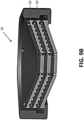
- FIG. 9B generally depicts a cross-sectional view of the flame arrestor 10 shown in FIG. 9A .
- the illustrated embodiment of the flame arrestor 10 shown in FIGS. 9A and 9B may be referred to as a "multiple-stage flame arrestor" that employs a "conic helical path concept.” That is, this particular embodiment may employ a conic flame path configuration.
- a helical three-dimensional groove may be included in a plate or module (e.g., a conical plate).
- An intended enclosure may be provided on top of, or above, the flame arrestor. However, if desired an enclosure could be provided on the bottom of, or below, a flame arrestor.
- a draining feature for the flame arrestor (such as discussed further in this disclosure) may be included on the bottom.
- the groove may be configured or designed so as not to be square or semi-circular.
- a plurality of holes may provide a gas flow path to an inner radial diameter in a helical stage/module, then at the next or subsequent stage/module the flow path may be configured to flow from the inner diameter to outer diameter in an upward direction, and then may subsequently/eventually flow out a related number of exit holes in the bottom of a last stage/module.
- FIG. 10A generally illustrates a portion of a flame arrestor 10 which is not within the scope of the claims.
- FIG. 10B generally depicts a cross-sectional view of the flame arrestor 10 shown in FIG. 10A .
- the flame arrestor 10 shown in FIGS. 10A and 10B may be referred to as a "multiple-stage flame arrestor” that employs a "cylindrical helical path concept.” That is, this flame arrestor may employ a cylindrical helical flame path configuration that may comprise a plurality of cylindrical stages/modules 50.
- a flame path may proceed toward the bottom of the arrestor 10 and may then spiral upwardly.
- Horizontal (radial) holes at the top of a stage may correspond to transfer/entry holes at the top of a next stage/module, which may spiral downwardly until the flame path eventually reaches exit holes (e.g., at an outer diameter at or about the bottom of the arrestor).
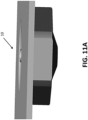
- FIG. 11A generally illustrates a portion of another embodiment of a flame arrestor 10 according to aspects of the present disclosure.
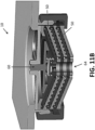
- FIG. 11B generally depicts a cross-sectional view of the flame arrestor 10 shown in FIG. 11A .
- the illustrated embodiment of the flame arrestor 10 shown in FIGS. 11A and 11B may be referred to as a "multiple-stage flame arrestor” that employs a "conic helical path concept with an input drain self-shutting valve.” That is, this particular embodiment may employ a conic flame path configuration (which may be similar to that associated with the embodiment of FIGS. 9A and 9B ) and may include a valve, e.g., an input drain self-shutting valve 60.
- a valve e.g., an input drain self-shutting valve 60.
- the flame arrestor 10 is shown without venting, and the input drain self-shutting valve 60 is shown provided toward the top side/portion of the flame arrestor prior to the modules.
- condensation can be trapped and permitted to come out.
- the valve can be configured to shut or shut-off flow.
- an associated drain hole e.g., drain hole 64
- the drain hole 64 may, for example and without limitation, have a 6.35 mm (0.25 inch) minimum diameter. It is noted that valves may be associated with planar or cylindrical flame arrestor concepts.
- a flame arrestor may assure venting capability.
- the flame arrestor may be referred to as a flame arrestor with ventilation.
- the flame arrestor may be coupled with a normally shut valve, and the normally shut valve may be configured to prevent the associated enclosure from ventilation.
- the flame arrestor may be referred to as a flame arrestor without ventilation.
- embodiments of a disclosed flame arrestor may be used with a self-shutting valve (e.g., a valve which may be configured to close under pressure from an explosion of a gas). In such a case, the device may be referred to as a flame arrestor with a drain.
- a drain valve may be included on an input side of a drain hole (see, e.g., FIG. 11B ), or on an output side of a drain hole (see, e.g., FIG. 12B ).
- a single module may be configured to employ a spiral groove as a gravity-fed drain so that no valve would be needed.
- embodiments of a flame arrestor may include a normally-open, self-shutting valve on both input and output ends or sides to provide additional robustness to a design.
- normally-open valves may be heated (e.g., by resistive electric heating/heaters) to better maintain material temperature (e.g., to maintain a temperature above a freezing point), which can help prevent ice build-up or other conditions that could affect or prevent valve closure.
- material temperature e.g., to maintain a temperature above a freezing point
- Such heating may also be directed to the flame path and flame path components to help prevent ice build-up and help ensure sufficient ventilation and function.
- a small hole may be provided to allow pressure in the main enclosure to equalize.
- Embodiments can be inherently venting-enabling, as the arrestor may be configured such that there is always a path running from inside to outside.
- the configuration can serve as a breather, among other things. That is, in embodiments, it may be desirable to suppress the breathing with the valve normally closed, and to release the valve if the pressure increases.
- FIG. 12A generally illustrates a portion of another embodiment of a flame arrestor 10 according to aspects of the present disclosure.
- FIG. 12B generally depicts a cross-sectional view of the flame arrestor 10 shown in FIG. 12A .
- the illustrated embodiment of the flame arrestor 10 shown in FIGS. 12A and 12B may be referred to as a "multiple-stage flame arrestor” that employs a "conic helical path concept with an output drain self-shutting valve.” That is, without limitation, this particular embodiment may employ a conic flame path configuration (which may be similar to that associated with the embodiment of FIGS. 9A and 9B ) and may include a drain valve 70, e.g., an output drain self-shutting valve.
- a drain valve such as drain valve 70
- planar or cylindrical concepts as generally disclosed herein.
- FIG. 11B An embodiment such as generally illustrated in FIG. 11B can add draining capability to the system or configuration.
- a spring-type valve may be included.
- a component 74 may move to initiate a seal, which may permit gases to release.
- Such a configuration may serve as a humidity/fluid deflector so, among other things, condensation will not block relevant holes. That is, embodiments can be configured so that the fluid can drain out and the gases can follow an intended path.
- the diameter of a by-pass may have a larger cross-sectional path than a main draining hole. With some configurations with a by-pass, an explosion can push a plug and close a path., which can force hot gas through a flame arrestor flame path.
- a membrane-type, or a ball-type valve may be employed, for example, to suppress venting capability when such a function is desired.
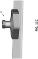
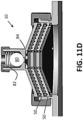
- a ball-type valve implemented in the context of the present disclosure is generally illustrated in FIGS. 11C and 11D .
- a ball 80 may be biased by a biasing mechanism (e.g., spring 82) toward an opening 84.
Landscapes
- Engineering & Computer Science (AREA)
- Public Health (AREA)
- Business, Economics & Management (AREA)
- Emergency Management (AREA)
- Health & Medical Sciences (AREA)
- Combustion & Propulsion (AREA)
- Chemical & Material Sciences (AREA)
- Mechanical Engineering (AREA)
- General Engineering & Computer Science (AREA)
- Fire-Detection Mechanisms (AREA)
- Fire-Extinguishing By Fire Departments, And Fire-Extinguishing Equipment And Control Thereof (AREA)
- Gas Burners (AREA)
- Valve Housings (AREA)
Description
- The present disclosure relates generally to flame arrestors, including modular flame arrestors that may include venting and/or draining capability, and that may be used in a wide range of applications, including aerospace applications.
- Flame arrestors have been used to prevent explosions from propagating inside or outside of an environment or enclosure. Flame arrestors can be used to help extinguish a flame, for instance, by decreasing the temperature of burning gases below an ignition point. That can be accomplished, for example, by (a) employing a longer flame path between an internal volume and an external environment, or (b) including a multitude of very small cross-sectional area flow paths, with the objective of transferring the heat from the burning gas to the flame arrestor and other components. Most existing flame arrestors are designed for large industrial fuel tanks or pipes. Such flame arrestors may address similar, but not identical needs, with respect to aerospace applications and needs, especially with respect to size and weight considerations. That is, with many aerospace applications, the enclosed empty volume will be intentionally minimized by design. Then a flame arrestor is employed to help prevent an internal flame from propagating outside the enclosure. With conventional aerospace flame arrestors, a long flame path is often used. That is, conventional aerospace designs are commonly based on a labyrinth flame path concept involving a series of cross-drilled holes. However, long flame paths can involve or result in, inter alia, a large and heavy device, large pressure drops, and very small flow cross-section areas can restrict draining capability and/or may be susceptible to plugging (e.g., from fouling and icing).
InUS 4 072 799 A there is disclosed a flame arrestor as it is defined in the pre-characterizing portion ofclaim 1. - Among other things, it can be desirable to provide flame arrestors that address some or all of the aforementioned challenges.
- The present invention is a flame arrestor as it is defined in
claim 1. The flame arrestor includes a flame arrestor collar and a flame arrestor plug. The collar is configured to connect the flame arrestor to a portion of an enclosure. The collar has one or more flame paths in the form of grooves formed in a radially expanded portion of the collar. The plug is configured to be inserted into and connected to the collar. The plug has a substantially vertical path in an insertion direction in which the plug is insertable into the collar and through which gas is flowable from the enclosure into the flame arrestor, radial paths extending radially outward from the substantially vertical path and in communication with the first side of the one or more flame paths such that the gas exits the radial paths into the one or more flame paths, and one or more exit apertures in a radially expanded portion of the plug and in communication with the second side of the one or more flame paths such that the gas exits the one or more flame paths into the one or more exit apertures and configured to allow the gas to exit the flame arrestor. The one or more flame paths includes a spiral or helical flame path which is provided within a radially expanded portion of the collar. Further embodiments of the flame arrestor are defined in the dependent claims. - The flame arrestor may include a collar that is configured for threaded connection with the plug.
- The flame arrestor may include a plurality of flame path modules or stages. The one or more of the plurality of flame path modules or stages may include an aperture configured to transfer gas to another module or stage. Each of the flame path modules or stages may include one or more grooves configured to transfer gas from a first side of the flame path to a second side of the flame path.
- Various aspects of the present disclosure will become apparent to those skilled in the art from the following detailed description of the various embodiments, when read in light of the accompanying drawings.
- Embodiments of the present disclosure will now be described, by way of example, with reference to the accompanying drawings.
-
FIG. 1A is side view of a flame arrestor according to an embodiment of the present disclosure; -
FIG. 1B is side cross-sectional view of the flame arrestor generally illustrated inFIG. 1A ; -
FIG. 2 is a perspective cross-sectional illustration of a flame arrestor which is not within the scope of the claims; -
FIG. 3A is a side view of a flame arrestor collar according to an embodiment of the present disclosure; -
FIG. 3B is a side cross-sectional view of the flame arrestor collar generally illustrated inFIG. 3A ; -
FIG. 3C is an enlarged cross-sectional view of a portion of the flame arrestor collar generally illustrated inFIG. 3B ; -
FIG. 3D is a bottom plan view of the flame arrestor collar generally illustrated inFIGS. 3A and3B ; -
FIG. 4A is a side cross-sectional view of a flame arrestor plug according to an embodiment of the present disclosure, the cross-section as noted inFIG. 4B ; -
FIG. 4B is a side cross-sectional view of the flame arrestor plug generally illustrated inFIG. 4A ; -
FIG. 4C is a cross-sectional bottom plan view of a portion of the flame arrestor plug generally illustrated inFIG. 4B ; -
FIG. 5 is an illustration of a "single-stage"-type embodiment of a flame arrestor shown assembled in an environment; -
FIG. 6 is an illustration of a single "single-stage"-type embodiment of a flame arrestor of the type depicted inFIG. 5 , shown with the flame arrestor plug removed; -
FIG. 7 is an illustration of a flame arrestor plug and flame arrestor collar according to an embodiment of the preset disclosure, shown separated; -
FIG. 8A is side view of a flame arrestor according to another embodiment of the present disclosure; -
FIG. 8B is side cross-sectional view of the flame arrestor generally illustrated inFIG. 8A ; -
FIG. 9A is side view of a flame arrestor according to another embodiment of the present disclosure; -
FIG. 9B is side cross-sectional view of the flame arrestor generally illustrated inFIG. 9A ; -
FIG. 10A is side view of a flame arrestor which is not within the scope of the claims; -
FIG. 10B is side cross-sectional view of the flame arrestor generally illustrated inFIG. 10A ; -
FIG. 11A is side view of a flame arrestor according to another embodiment of the present disclosure; -
FIG. 11B is side cross-sectional view of the flame arrestor generally illustrated inFIG. 11A ; -
FIG. 11C is a side view of flame arrestor according to another embodiment of the present disclosure; -
FIG. 11D is a side cross-sectional view of the flame arrestor generally illustrated inFIG. 11D ; -
FIG. 12A is side view of a flame arrestor according to another embodiment of the present disclosure; and -
FIG. 12B is side cross-sectional view of the flame arrestor generally illustrated inFIG. 12A . - Reference will now be made in detail to embodiments of the present disclosure, examples of which are described herein and illustrated in the accompanying drawings. While the invention will be described in conjunction with embodiments, it will be understood that they are not intended to limit the invention to these embodiments. On the contrary, the invention is intended to cover alternatives and modifications which may be included within the scope of the invention as defined by the appended claims.
-
FIG. 1A generally illustrates an embodiment of aflame arrestor 10 according to aspects of the present disclosure.FIG. 1B generally illustrates a cross-sectional view of theflame arrestor 10 shown inFIG. 1A . Theflame arrestor 10 may include a flame arrestor collar (or collar) 20 and a flame arrestor plug (or plug) 30, which are generally illustrated inFIGS. 1A and1B in an assembled configuration. For example, and without limitation,FIG. 2 generally illustrates how aplug 30 may be connected to acollar 20, such as via a threaded connection. In embodiments, flame arrestors may be configured to confine or maintain an internal explosion and may provide a means to drain fluid while stopping a flame from exiting the flame arrestor. - In embodiments a
flame arrestor 10, as generally illustrated inFIGS. 1A and1B , may be referred to as a "single-stage flame arrestor" or a "single-stage plane disk flame arrestor." Theflame arrestor 10 may connect to or engage with an enclosure, which is generically shown inFIG. 1B for positional environmental purposes only, as enclosure E. Although, as those of skill in the art will appreciate, the present disclosure is not limited to a particular type or form of associated enclosure. In embodiments, a portion of theflame arrestor 10 may be configured for a suitably solid or firm engagement with a portion of enclosure E. For example, and without limitation, a portion ofcollar 20 may be configured for a threaded engagement with a portion of an enclosure E. Male threading may be provided on thecollar 20 and female threading may be provided in the enclosure E, or vice versa. - In embodiments, a gas from an enclosure (e.g., enclosure E) may enter the
flame arrestor 10 and flow downwardly through a one or more openings and/or holes disposed on thecollar 20. The gas may flow downwardly through a first substantially vertical path (e.g., path 32) associated with the one or more openings. The gases may generally flow in depicted direction P1. Path 32 may eventually encounter and/or flow into, one or more connected paths. In embodiments, gases flowing frompath 32 may flow into depictedradial paths radial paths flame path 22, which may be formed in thecollar 20. In embodiments, a "spiral" or "helical" flame path may be provided in a radially expanded portion ofcollar 20. The gases entering the flame path may move from an inner diameter to an outer diameter and rotate to holes provided at or about the outer diameter. The "spiral" configuration can extend, and/or optimize or maximize, the flame path associated with theflame arrestor 10 to, inter alia, serve to cool gases that may enter the flame path. Employing an extended, and in this instance "spiral," flame path may permit a comparatively longer flame length, while minimizing the weight and the pressure drop associated with a flame arrestor. Moreover, in embodiments, the ratio of flame path length to the cross section diameter may vary by portion or segment. For example and without limitation, in embodiments, the ratio of flame path length to the cross section diameter may be about 50:1 at an input portion, may be about 60:1 through the grooves, and may be about 70:1 at an output portion. However, the concept is not limited to the forgoing specific ratios and/or variations, and the ratio might, for example and without limitation, be about 200:1 for a harsh environment and may be about 10:1 for a gentle environment. - Eventually, such as generally illustrated in
FIG. 1B , the flame path(s) provided incollar 20 may interface or interconnect with one or more exit paths - e.g.,exit paths plug 30, which may comprise holes or apertures provided inplug 30. -
FIGS. 3A through 3D generally illustrate an exemplary embodiment of a spiral pathtypeflame arrestor collar 20. While a number or details and/or dimensions may be included withFIGS. 3A to 3D to help teach concepts, the present disclosure is not limited to such specifics, and those of skill in the art will understand that various other specific sizes, shapes, dimensions, and path configurations may be employed within the scope of the disclosed concepts For example and without limitation, and as generally illustrated inFIG. 3A , an embodiment of acollar 20 may include dimensions A1, which may be about 1.270 cm (0.500 inches); A2, which may be about 1.067 cm (0.420 inches); A3, which may be about 2.54 mm (0.10 inches); A4, which may be about 1.372 cm (0.540 inches); and A5, which may be about 5.842 mm (0.230 inches). Also, for example and without limitation, and as generally illustrated inFIG. 3B , a cross-sectional view of an embodiment of thecollar 20 may include dimensions B1, which may be about 3.302 mm (0.130 inches); B2, which may be about 6.350 mm (0.250 inches); B3, which may be about 6,858 mm (0.270 inches); and B4, which may be between 3.188 cm (1.255 inches) and 3.195 cm (1.258 inches). Also, for example and without limitation,FIG. 3C illustrates an enlarged detailed view of a portion of thecollar 20 depicted inFIG. 3B . The portion of thecollar 20 may, for example and without limitation, include dimension C1, which may range between 1.448 mm (0.057 inches) and 1.702 mm (0.067 inches); C2, which may range between 1.448 mm (0.057 inches) and 1.702 mm (0.067 inches); C3, which range between 0.254 mm (0.010 inches) and 0.508 mm ( 0.020 inches); C4, which may range between 0.381 mm (0.015 inches) at about 40° and 0.635 mm (0.025 inches) at about 50°; C5, which may range between 2.934 cm (1.155 inches) and 2.959 cm (1.165 inches); and C6, which may range between 1.143 mm (0.045 inches) and 1.397 mm (0.055 inches). In embodiments, the spiral groove, as generally illustrated inFIG. 3C , may be +/- 2.54 mm (0.100 inches) and a pitch break edge may be +/- 0.127 mm (0.005 inches). -
FIG. 3D generally illustrates a spiral groove wall configuration that forms a spiral flame path. The spiral flame path may, for example and without limitation, include dimensions D1, which may be about 3.810 cm (1.500 inches), and D2, which may range between 3.467 cm (1.365 inches) and 3.495 cm (1.376 inches). It is noted that the cross sections may be circular, but it may be simpler to manufacture square cross sections, which may closely emulate the function of circular cross sections. The grooves employed in the various embodiments may serve, inter alia, as a collector. In embodiments, portions of the spiral groove wall, such as shown inFIG. 3D , may be ground to insure a minimum wall thickness - for example and without limitation, a thickness of about 0.762 mm (0.030 inches). - For embodiments in which comparatively longer flame paths are desired or employed, there may be design concerns regarding potential blockage. Consequently, with embodiments, including those described herein, multiple (or alternate) flame paths may be included to provide alternative paths - which can help prevent blockage. For example, with the inclusion of multiple flame paths, if one flame path is blocked by debris, dust, grease, dirt, etc., another flame path or flame paths may remain functional.
-
FIGS. 4A through 4C generally illustrate an exemplary embodiment of a spiral pathtypeflame arrestor plug 30. While a number or details and/or dimensions may be included withFIGS. 4A to 4C or other figures herein to help teach concepts, the present disclosure is not limited to such specifics, and those of skill in the art will understand that various other specific sizes, shapes, dimensions, and path configurations may be employed within the scope of the disclosed concepts.FIG. 4A illustrates a cross-sectional view of an embodiment of aplug 30, as generally shown inFIG. 4B . Theplug 30 may, for example and without limitation, include dimension E1, which may be about 6.350 mm (0.250 inches); E2, which may range between 5.953 cm (0.195 inches) and 5.207 mm (0.205 inches); E3, which may be about 1.702 cm (0.670 inches); E4, which may be about 1.270 cm (0.500 inches); E5, which may range between 1.143 mm (0.045 inches) and 1.397 mm (0.055 inches); E6, which may be about 0.762 mm (0.030 inches); and E7, which may range between 3.167 cm (1.247 inches) and 3.175 cm (1.250 inches). In a corresponding manner,FIG. 4B generally illustrates a cross-sectional view of theplug 30 as generally shown inFIG. 4A . Theplug 30 may, for example and without limitation, include dimension F1, which may range between 1.143 mm (0.045 inches) and 1.397 mm (0.055 inches); F2, which may represent a length of an aperture disposed within the collar, and may range between 1.867 cm (0.735 inches) and 1.892 cm (0.745 inches); F3, which may, for example, be associated with four equidistantly-spaced holes, having a diameter of between 1.448 mm (0.057 inches) and 1.702 mm (0.067 inches); F4, which may be about 1.270 mm (0.050 inches); F5, which may be about 1.524 mm (0.060 inches); F6, which may be about 3.048 mm (0.120 inches); F7, which may be about 1.981 cm (0.780 inches); F8, which may range between 0.254 mm (0.010 inches) at about 40° and 0.762 mm (0.030 inches) at about 50°; and F9, which may be about 2.794 cm (1.100 inches).FIG. 4C generally illustrates a cross-sectional bottom plan view of a portion of theflame arrestor plug 30, such as generally illustrated inFIG. 4B . Theplug 30 may, for example and without limitation, include dimension G1, which may range between 1.143 mm (0.045 inches) and 1.397 mm (0.055 inches); G2, which may be about 6.299 mm (0.248 inches); G3, which may range between 1.245 cm (0.490 inches) and 1.275 cm (0.502 inches); and G4, which may be about 1.270 mm (0.05 inches). -
FIG. 5 generally illustrates an embodiment of a single-stage flame arrestor 10 shown in an assembled condition and connected to a component. In the illustrated embodiment, an outer hex - which may be turned by a wrench - may be used to lock the parts together.FIG. 6 generally illustrates the flame arrestor ofFIG. 5 , but with theplug 30 shown removed, which better demonstrates an instance of a spiral or helical flame path. Embodiments of acollar 20 and aplug 30 are separately and generally illustrated inFIG. 7 . -
FIG. 8A generally illustrates another embodiment of aflame arrestor 10 according to aspects of the present disclosure.FIG. 8B generally depicts a cross-sectional view of theflame arrestor 10 shown inFIG. 8A . For example and without limitation, the illustrated embodiment of theflame arrestor 10 shown inFIGS. 8A and8B may be referred to as a "multiple-stage flame arrestor." This particular embodiment may also employ a spiral or helical flame path configuration. In embodiments, a flame path (e.g., a spiral or helical flame path) may comprise a plurality or series of flame path stages or plates (e.g., flat plates) - which may also be referred to herein as amodule 50, or as modules in the plural. In embodiments, the number of modules (such as module(s) 50) may be can be adjusted (e.g., increased or decreased) to achieve a designed or desired flame path for a given design envelope and weight. - In embodiments, all grooves may start from a common, typically circular, collector groove, and may end in a common, typically circular, collector groove. The passage between adjacent modules may comprise passages (e.g., holes or apertures) through the inner or outer collector groove, as needed or desired. In embodiments, the radially outer diameter of a flame path in a first (e.g., top) module or stage may have holes that are configured to transfer gas to corresponding holes associated with an inner radial diameter of a next (e.g., bottom or lower) module or stage. In this manner, the
modules 50 may be configured to allow gas to flow from a first side of a flame path to a second side of a flame path. For example and without limitation, themodules 50 may be configured to allow gas to flow from an entry side of a flame path (e.g., a first side and/or a side gas enters the flame path) to an exit side of the flame path (e.g., a second side and/or a side gas exits the flame path). The shape (e.g., cross-sectional shape) of the groove or path may be intentionally or arbitrarily selected, may be round or square or other suitable shape, and may be manufactured on one or both sides of the module. Various manufacturing processes can be used to create the groove(s). For example and without limitation, machining, use of a spiral or helical coil wire between plates, etc. Embodiments of the disclosed concept, which may increase the length of a flame path, may provide for a drop in temperature without causing a substantial pressure drop and/or may provide a reduction in space and weight. Reducing or minimizing pressure drop can be significant because with a long groove if there is a very large pressure drop the release will not be very fast. - It is noted that if modules or stages are not sealed together, configurations may have a minimized gap to create a quasi-seal. For embodiments, such a minimized gap may, for example and without limitation, be about 0.127 mm (0.005 inches).
-
FIG. 9A generally illustrates a portion of another embodiment of aflame arrestor 10 according to aspects of the present disclosure.FIG. 9B generally depicts a cross-sectional view of theflame arrestor 10 shown inFIG. 9A . For example and without limitation, the illustrated embodiment of theflame arrestor 10 shown inFIGS. 9A and9B may be referred to as a "multiple-stage flame arrestor" that employs a "conic helical path concept." That is, this particular embodiment may employ a conic flame path configuration. - In the illustrated embodiment, a helical three-dimensional groove may be included in a plate or module (e.g., a conical plate). An intended enclosure may be provided on top of, or above, the flame arrestor. However, if desired an enclosure could be provided on the bottom of, or below, a flame arrestor. Moreover, if needed or desired, a draining feature for the flame arrestor (such as discussed further in this disclosure) may be included on the bottom. In embodiments, the groove may be configured or designed so as not to be square or semi-circular. For example and without limitation, in an embodiment, a plurality of holes (e.g., three holes) may provide a gas flow path to an inner radial diameter in a helical stage/module, then at the next or subsequent stage/module the flow path may be configured to flow from the inner diameter to outer diameter in an upward direction, and then may subsequently/eventually flow out a related number of exit holes in the bottom of a last stage/module.
-
FIG. 10A generally illustrates a portion of aflame arrestor 10 which is not within the scope of the claims.FIG. 10B generally depicts a cross-sectional view of theflame arrestor 10 shown inFIG. 10A . For example and without limitation, theflame arrestor 10 shown inFIGS. 10A and 10B may be referred to as a "multiple-stage flame arrestor" that employs a "cylindrical helical path concept." That is, this flame arrestor may employ a cylindrical helical flame path configuration that may comprise a plurality of cylindrical stages/modules 50. In the illustrated embodiment, a flame path may proceed toward the bottom of thearrestor 10 and may then spiral upwardly. Horizontal (radial) holes at the top of a stage may correspond to transfer/entry holes at the top of a next stage/module, which may spiral downwardly until the flame path eventually reaches exit holes (e.g., at an outer diameter at or about the bottom of the arrestor). -
FIG. 11A generally illustrates a portion of another embodiment of aflame arrestor 10 according to aspects of the present disclosure.FIG. 11B generally depicts a cross-sectional view of theflame arrestor 10 shown inFIG. 11A . For example and without limitation, the illustrated embodiment of theflame arrestor 10 shown inFIGS. 11A and11B may be referred to as a "multiple-stage flame arrestor" that employs a "conic helical path concept with an input drain self-shutting valve." That is, this particular embodiment may employ a conic flame path configuration (which may be similar to that associated with the embodiment ofFIGS. 9A and9B ) and may include a valve, e.g., an input drain self-shuttingvalve 60. In the illustrated embodiment, theflame arrestor 10 is shown without venting, and the input drain self-shuttingvalve 60 is shown provided toward the top side/portion of the flame arrestor prior to the modules. With the embodiment, condensation can be trapped and permitted to come out. However, in the event of an explosion, the valve can be configured to shut or shut-off flow. With embodiments, an associated drain hole (e.g., drain hole 64) may be fairly large, comparatively, to allow water or condensation to exit. In an embodiment, thedrain hole 64 may, for example and without limitation, have a 6.35 mm (0.25 inch) minimum diameter. It is noted that valves may be associated with planar or cylindrical flame arrestor concepts. - With embodiments in which the flame path is permanently opened, a flame arrestor may assure venting capability. In such cases, the flame arrestor may be referred to as a flame arrestor with ventilation. In other embodiments, if and when venting capability is not needed, the flame arrestor may be coupled with a normally shut valve, and the normally shut valve may be configured to prevent the associated enclosure from ventilation. In this case, the flame arrestor may be referred to as a flame arrestor without ventilation. Additionally, embodiments of a disclosed flame arrestor may be used with a self-shutting valve (e.g., a valve which may be configured to close under pressure from an explosion of a gas). In such a case, the device may be referred to as a flame arrestor with a drain. In embodiments, a drain valve may be included on an input side of a drain hole (see, e.g.,
FIG. 11B ), or on an output side of a drain hole (see, e.g.,FIG. 12B ). Moreover, with the application of a conical concept flame, such as previously described, in embodiments a single module may be configured to employ a spiral groove as a gravity-fed drain so that no valve would be needed. Additionally, embodiments of a flame arrestor may include a normally-open, self-shutting valve on both input and output ends or sides to provide additional robustness to a design. If desired, normally-open valves may be heated (e.g., by resistive electric heating/heaters) to better maintain material temperature (e.g., to maintain a temperature above a freezing point), which can help prevent ice build-up or other conditions that could affect or prevent valve closure. Such heating may also be directed to the flame path and flame path components to help prevent ice build-up and help ensure sufficient ventilation and function. - In embodiments, and with respect to venting, a small hole may be provided to allow pressure in the main enclosure to equalize. Embodiments can be inherently venting-enabling, as the arrestor may be configured such that there is always a path running from inside to outside. The configuration can serve as a breather, among other things. That is, in embodiments, it may be desirable to suppress the breathing with the valve normally closed, and to release the valve if the pressure increases.
-
FIG. 12A generally illustrates a portion of another embodiment of aflame arrestor 10 according to aspects of the present disclosure.FIG. 12B generally depicts a cross-sectional view of theflame arrestor 10 shown inFIG. 12A . For example and without limitation, the illustrated embodiment of theflame arrestor 10 shown inFIGS. 12A and12B may be referred to as a "multiple-stage flame arrestor" that employs a "conic helical path concept with an output drain self-shutting valve." That is, without limitation, this particular embodiment may employ a conic flame path configuration (which may be similar to that associated with the embodiment ofFIGS. 9A and9B ) and may include a drain valve 70, e.g., an output drain self-shutting valve. Again, a drain valve (such as drain valve 70) may be employed with planar or cylindrical concepts as generally disclosed herein. - An embodiment such as generally illustrated in
FIG. 11B can add draining capability to the system or configuration. In embodiments, a spring-type valve may be included. For example, and without limitation, as pressure builds acomponent 74 may move to initiate a seal, which may permit gases to release. Such a configuration may serve as a humidity/fluid deflector so, among other things, condensation will not block relevant holes. That is, embodiments can be configured so that the fluid can drain out and the gases can follow an intended path. It is noted that with embodiments, the diameter of a by-pass may have a larger cross-sectional path than a main draining hole. With some configurations with a by-pass, an explosion can push a plug and close a path., which can force hot gas through a flame arrestor flame path. - It is noted that for some embodiments a membrane-type, or a ball-type valve, may be employed, for example, to suppress venting capability when such a function is desired. Without limitation, an embodiment of a ball-type valve implemented in the context of the present disclosure is generally illustrated in
FIGS. 11C and11D . As generally shown in the illustrated embodiment, aball 80 may be biased by a biasing mechanism (e.g., spring 82) toward anopening 84. - The foregoing descriptions of specific embodiments of the present invention have been presented for purposes of illustration and description. They are not intended to be exhaustive or to limit the invention to the precise forms disclosed, and various modifications and variations are possible in light of the above teaching. The embodiments were chosen and described in order to explain the principles of the invention and its practical application, to thereby enable others skilled in the art to utilize the invention and various embodiments with various modifications as are suited to the particular use contemplated. The scope of the invention is defined by the appended claims.
Claims (9)
- A flame arrestor (10) comprising:a collar (20) configured to connect the flame arrestor (10) to a portion of an enclosure (E), the collar having one or more flame paths in the form of grooves formed in a radially expanded portion of the collar; anda plug (30) configured to be inserted into and connected to the collar (20), the plug having a substantially vertical path (32) in an insertion direction in which the plug is insertable into the collar and through which gas is flowable from the enclosure (E) into the flame arrestor, radial paths (34a, 34b) extending radially outward from the substantially vertical path and in communication with a first side of the one or more flame paths such that the gas exits the radial paths into the one or more flame paths, and one or more exit apertures (36a, 36b) in a radially expanded portion of the plug and in communication with a second side of the one or more flame paths such that the gas exits the one or more flame paths into the one or more exit apertures and configured to allow the gas to exit the flame arrestor;characterized in thatthe one or more flame paths includes a spiral or helical flame path which is provided within a radially expanded portion of the collar (20).
- The flame arrestor of claim 1, wherein the collar (20) is configured for threaded connection to the plug (30).
- The flame arrestor of claim 1, wherein a ratio of flame path length to cross section diameter varies by portion or segment of the flame arrestor.
- The flame arrestor of claim 1, wherein a ratio of flame path length to the cross section diameter is about 200:1 or greater, or is about 50:1 at an input portion and about 70:1 at an output portion.
- The flame arrestor of claim 1, comprising a plurality of flame path modules (50) or stages.
- The flame arrestor of claim 5, wherein one or more of the plurality of flame path modules (50) or stages includes an aperture configured to transfer gas to another module or stage.
- The flame arrestor of claim 5, wherein the plurality of flame path modules (50) or stages comprise a plurality of plates.
- The flame arrestor of claim 1, wherein the collar (20) includes a plurality of threads configured for connection to a portion of said enclosure (E).
- The flame arrestor of claim 1, including a plurality of flame paths configured to provide alternative flame paths.
Applications Claiming Priority (1)
| Application Number | Priority Date | Filing Date | Title |
|---|---|---|---|
| US201562149143P | 2015-04-17 | 2015-04-17 |
Publications (3)
| Publication Number | Publication Date |
|---|---|
| EP3081266A2 EP3081266A2 (en) | 2016-10-19 |
| EP3081266A3 EP3081266A3 (en) | 2016-12-28 |
| EP3081266B1 true EP3081266B1 (en) | 2023-11-29 |
Family
ID=55854573
Family Applications (1)
| Application Number | Title | Priority Date | Filing Date |
|---|---|---|---|
| EP16165224.3A Active EP3081266B1 (en) | 2015-04-17 | 2016-04-14 | Flame arrestor |
Country Status (2)
| Country | Link |
|---|---|
| US (1) | US10890325B2 (en) |
| EP (1) | EP3081266B1 (en) |
Families Citing this family (12)
| Publication number | Priority date | Publication date | Assignee | Title |
|---|---|---|---|---|
| CN105327474A (en) * | 2014-08-14 | 2016-02-17 | 张家港中集圣达因低温装备有限公司 | Low-temperature storage transportation container and ice-blockage-prevention system of fire barrier of low-temperature storage transportation container |
| US10890325B2 (en) * | 2015-04-17 | 2021-01-12 | Eaton Intelligent Power Limited | Flame arrestor |
| GB2549784B (en) * | 2016-04-29 | 2021-12-22 | Elmac Tech Limited | Flame arresters |
| US9987508B2 (en) | 2016-08-31 | 2018-06-05 | Emerson Process Management Regulator Technologies Tulsa, Llc | Hybrid composite flame cell |
| US20180056100A1 (en) | 2016-08-31 | 2018-03-01 | Emerson Process Management Regulator Technologies Tulsa, Llc | Method for Manufacturing a Flame Arrestor |
| GB201707857D0 (en) | 2017-05-16 | 2017-06-28 | Elmac Tech Ltd | Valve apparatus |
| US11168883B2 (en) * | 2017-09-29 | 2021-11-09 | Rosemount Aerospace Inc. | Flame arrestor with fluid drainage capabilities |
| US11691040B2 (en) | 2019-01-08 | 2023-07-04 | The Boeing Company | Flame arrestor |
| US11852152B2 (en) | 2019-10-07 | 2023-12-26 | The Gorman-Rupp Company | Pin vent assembly |
| US11992721B2 (en) * | 2020-07-08 | 2024-05-28 | Rosemount Inc. | Flame arrester for process devices |
| US12013116B2 (en) * | 2021-02-26 | 2024-06-18 | Emerson Process Management Regulator Tech Inc. | Flame arrestors and methods of making flame arrestors |
| USD1054527S1 (en) | 2022-02-12 | 2024-12-17 | Mark W Wyne | Flame arrestor |
Family Cites Families (19)
| Publication number | Priority date | Publication date | Assignee | Title |
|---|---|---|---|---|
| US3356255A (en) * | 1967-12-05 | Breather and drain | ||
| NL8411C (en) * | 1918-03-18 | |||
| US1799565A (en) * | 1927-10-24 | 1931-04-07 | Warren City Tank & Boiler Comp | Vent and flame arrester |
| US4072799A (en) | 1977-04-13 | 1978-02-07 | Esb Incorporated | Vent plug system for batteries |
| DE2815242C2 (en) * | 1978-04-08 | 1979-09-13 | Messer Griesheim Gmbh, 6000 Frankfurt | Autogenous welding and / or cutting torch |
| US4317868A (en) | 1980-09-19 | 1982-03-02 | Gould Inc. | Battery vent plug with flame arrestor |
| DE3135461A1 (en) * | 1981-07-02 | 1983-01-20 | Gerätebau Insul-Ahr Karl-Friedrich Simsheuser, 5489 Insul | Safety device for safeguarding the gas lines of welding, cutting and soldering equipment from explosions and backflow of gas |
| DE3136189A1 (en) * | 1981-09-12 | 1983-03-31 | Messer Griesheim Gmbh, 6000 Frankfurt | Gas-welding and/or gas-cutting torch |
| US4444109A (en) * | 1982-11-19 | 1984-04-24 | Hercules Incorporated | Flame arrestor device with pourous membrane |
| US5017129A (en) * | 1990-02-06 | 1991-05-21 | Scheu Manufacturing Company | Porous ceramic gas burner |
| US5203296A (en) * | 1992-04-09 | 1993-04-20 | Barbron Corporation | Flame arrester having helical flame arresting member |
| JPH0814509A (en) * | 1994-07-01 | 1996-01-19 | Paloma Ind Ltd | Pulse burner |
| DE10336530B3 (en) * | 2003-08-05 | 2005-02-17 | Leinemann Gmbh & Co. | Flame arrester |
| US20050286834A1 (en) * | 2003-12-22 | 2005-12-29 | Bae Systems Plc | Waveguide assembly and connector |
| DE102007000143B4 (en) | 2007-03-09 | 2010-07-15 | Wika Alexander Wiegand Gmbh & Co. Kg | Acetylene pressure gauge with protective choke |
| WO2011005895A1 (en) * | 2009-07-07 | 2011-01-13 | Firestar Engineering Llc | Aluminum porous media |
| US8485040B2 (en) | 2011-03-14 | 2013-07-16 | Rosemount Inc. | Flame arrestor for process transmitter |
| US20140030666A1 (en) * | 2012-07-30 | 2014-01-30 | Victor Equipment Company | Flashback arrestor |
| US10890325B2 (en) * | 2015-04-17 | 2021-01-12 | Eaton Intelligent Power Limited | Flame arrestor |
-
2016
- 2016-03-23 US US15/078,645 patent/US10890325B2/en active Active
- 2016-04-14 EP EP16165224.3A patent/EP3081266B1/en active Active
Also Published As
| Publication number | Publication date |
|---|---|
| EP3081266A3 (en) | 2016-12-28 |
| EP3081266A2 (en) | 2016-10-19 |
| US10890325B2 (en) | 2021-01-12 |
| US20160305653A1 (en) | 2016-10-20 |
Similar Documents
| Publication | Publication Date | Title |
|---|---|---|
| EP3081266A2 (en) | Flame arrestor | |
| EP3082980B1 (en) | Protection device against the propagation of flames comprising flame arrester blocks | |
| US20050268967A1 (en) | Surge suppression and safety cut-off valve | |
| US11806643B2 (en) | Drain valve and valve arrangement | |
| EP3200882B1 (en) | Flame arresters | |
| EP3448530B1 (en) | Flame arresters | |
| US20140083667A1 (en) | Tri-Piece Thermal Energy Body Heat Exchanger Having Multi-Layer Pipeline And Transferring Heat To Exterior Through Outer Periphery Of Pipeline | |
| CN107270004A (en) | Stream formation structure | |
| US20140083666A1 (en) | Tri-Piece Thermal Energy Body Heat Exchanger Having Multi-Layer Pipeline and Transferring Heat to Exterior Through Outer Periphery of Pipeline | |
| US9927046B2 (en) | Throttling device | |
| US8807224B2 (en) | Subsea arrangement | |
| CN103423582B (en) | Self-adjusting flow steam cooler | |
| CA2989905C (en) | Heat exchange device | |
| EP3382243B1 (en) | Safety valve unit, in particular for protecting a storage water heater | |
| CN110050158A (en) | Reduction mechanism and flame arrester with reduction mechanism | |
| CN103063073A (en) | Liquid separating core and multi-stage cooling heat exchanger with liquid separating core | |
| CN203500824U (en) | Self-adjusting flow steam cooler | |
| US20160375285A1 (en) | Flame arrestor assembly | |
| CN105737465B (en) | Device for drying and filtering | |
| WO2014207736A1 (en) | Air release valve with elastic rolling shutter | |
| CN205026780U (en) | Back -flow preventer and oil extraction tobacco pipe way | |
| KR102588129B1 (en) | Tent cover for preventing fire-flakes of stovepipe | |
| KR101521209B1 (en) | Explosion-induced Pressure Cutoff Valve and Launching-Tube Air Conditioning System using the same | |
| CN213088788U (en) | Filter regulating valve | |
| CN204240662U (en) | Heat exchange system |
Legal Events
| Date | Code | Title | Description |
|---|---|---|---|
| PUAI | Public reference made under article 153(3) epc to a published international application that has entered the european phase |
Free format text: ORIGINAL CODE: 0009012 |
|
| AK | Designated contracting states |
Kind code of ref document: A2 Designated state(s): AL AT BE BG CH CY CZ DE DK EE ES FI FR GB GR HR HU IE IS IT LI LT LU LV MC MK MT NL NO PL PT RO RS SE SI SK SM TR |
|
| AX | Request for extension of the european patent |
Extension state: BA ME |
|
| PUAL | Search report despatched |
Free format text: ORIGINAL CODE: 0009013 |
|
| AK | Designated contracting states |
Kind code of ref document: A3 Designated state(s): AL AT BE BG CH CY CZ DE DK EE ES FI FR GB GR HR HU IE IS IT LI LT LU LV MC MK MT NL NO PL PT RO RS SE SI SK SM TR |
|
| AX | Request for extension of the european patent |
Extension state: BA ME |
|
| RIC1 | Information provided on ipc code assigned before grant |
Ipc: A62C 4/00 20060101AFI20161124BHEP Ipc: A62C 4/02 20060101ALI20161124BHEP Ipc: A62C 3/08 20060101ALN20161124BHEP |
|
| STAA | Information on the status of an ep patent application or granted ep patent |
Free format text: STATUS: REQUEST FOR EXAMINATION WAS MADE |
|
| 17P | Request for examination filed |
Effective date: 20170627 |
|
| RBV | Designated contracting states (corrected) |
Designated state(s): AL AT BE BG CH CY CZ DE DK EE ES FI FR GB GR HR HU IE IS IT LI LT LU LV MC MK MT NL NO PL PT RO RS SE SI SK SM TR |
|
| STAA | Information on the status of an ep patent application or granted ep patent |
Free format text: STATUS: EXAMINATION IS IN PROGRESS |
|
| 17Q | First examination report despatched |
Effective date: 20200316 |
|
| RAP1 | Party data changed (applicant data changed or rights of an application transferred) |
Owner name: EATON INTELLIGENT POWER LIMITED |
|
| P01 | Opt-out of the competence of the unified patent court (upc) registered |
Effective date: 20230521 |
|
| RIC1 | Information provided on ipc code assigned before grant |
Ipc: A62C 3/08 20060101ALN20230629BHEP Ipc: A62C 4/02 20060101ALI20230629BHEP Ipc: A62C 4/00 20060101AFI20230629BHEP |
|
| GRAP | Despatch of communication of intention to grant a patent |
Free format text: ORIGINAL CODE: EPIDOSNIGR1 |
|
| STAA | Information on the status of an ep patent application or granted ep patent |
Free format text: STATUS: GRANT OF PATENT IS INTENDED |
|
| RIC1 | Information provided on ipc code assigned before grant |
Ipc: A62C 3/08 20060101ALN20230828BHEP Ipc: A62C 4/02 20060101ALI20230828BHEP Ipc: A62C 4/00 20060101AFI20230828BHEP |
|
| INTG | Intention to grant announced |
Effective date: 20230913 |
|
| GRAS | Grant fee paid |
Free format text: ORIGINAL CODE: EPIDOSNIGR3 |
|
| GRAA | (expected) grant |
Free format text: ORIGINAL CODE: 0009210 |
|
| STAA | Information on the status of an ep patent application or granted ep patent |
Free format text: STATUS: THE PATENT HAS BEEN GRANTED |
|
| AK | Designated contracting states |
Kind code of ref document: B1 Designated state(s): AL AT BE BG CH CY CZ DE DK EE ES FI FR GB GR HR HU IE IS IT LI LT LU LV MC MK MT NL NO PL PT RO RS SE SI SK SM TR |
|
| REG | Reference to a national code |
Ref country code: GB Ref legal event code: FG4D |
|
| REG | Reference to a national code |
Ref country code: CH Ref legal event code: EP |
|
| REG | Reference to a national code |
Ref country code: DE Ref legal event code: R096 Ref document number: 602016084361 Country of ref document: DE |
|
| REG | Reference to a national code |
Ref country code: IE Ref legal event code: FG4D |
|
| REG | Reference to a national code |
Ref country code: LT Ref legal event code: MG9D |
|
| REG | Reference to a national code |
Ref country code: NL Ref legal event code: MP Effective date: 20231129 |
|
| PG25 | Lapsed in a contracting state [announced via postgrant information from national office to epo] |
Ref country code: GR Free format text: LAPSE BECAUSE OF FAILURE TO SUBMIT A TRANSLATION OF THE DESCRIPTION OR TO PAY THE FEE WITHIN THE PRESCRIBED TIME-LIMIT Effective date: 20240301 |
|
| PG25 | Lapsed in a contracting state [announced via postgrant information from national office to epo] |
Ref country code: IS Free format text: LAPSE BECAUSE OF FAILURE TO SUBMIT A TRANSLATION OF THE DESCRIPTION OR TO PAY THE FEE WITHIN THE PRESCRIBED TIME-LIMIT Effective date: 20240329 |
|
| PG25 | Lapsed in a contracting state [announced via postgrant information from national office to epo] |
Ref country code: LT Free format text: LAPSE BECAUSE OF FAILURE TO SUBMIT A TRANSLATION OF THE DESCRIPTION OR TO PAY THE FEE WITHIN THE PRESCRIBED TIME-LIMIT Effective date: 20231129 |
|
| PG25 | Lapsed in a contracting state [announced via postgrant information from national office to epo] |
Ref country code: ES Free format text: LAPSE BECAUSE OF FAILURE TO SUBMIT A TRANSLATION OF THE DESCRIPTION OR TO PAY THE FEE WITHIN THE PRESCRIBED TIME-LIMIT Effective date: 20231129 |
|
| PG25 | Lapsed in a contracting state [announced via postgrant information from national office to epo] |
Ref country code: LT Free format text: LAPSE BECAUSE OF FAILURE TO SUBMIT A TRANSLATION OF THE DESCRIPTION OR TO PAY THE FEE WITHIN THE PRESCRIBED TIME-LIMIT Effective date: 20231129 Ref country code: IS Free format text: LAPSE BECAUSE OF FAILURE TO SUBMIT A TRANSLATION OF THE DESCRIPTION OR TO PAY THE FEE WITHIN THE PRESCRIBED TIME-LIMIT Effective date: 20240329 Ref country code: GR Free format text: LAPSE BECAUSE OF FAILURE TO SUBMIT A TRANSLATION OF THE DESCRIPTION OR TO PAY THE FEE WITHIN THE PRESCRIBED TIME-LIMIT Effective date: 20240301 Ref country code: ES Free format text: LAPSE BECAUSE OF FAILURE TO SUBMIT A TRANSLATION OF THE DESCRIPTION OR TO PAY THE FEE WITHIN THE PRESCRIBED TIME-LIMIT Effective date: 20231129 Ref country code: BG Free format text: LAPSE BECAUSE OF FAILURE TO SUBMIT A TRANSLATION OF THE DESCRIPTION OR TO PAY THE FEE WITHIN THE PRESCRIBED TIME-LIMIT Effective date: 20240229 |
|
| REG | Reference to a national code |
Ref country code: AT Ref legal event code: MK05 Ref document number: 1635521 Country of ref document: AT Kind code of ref document: T Effective date: 20231129 |
|
| PG25 | Lapsed in a contracting state [announced via postgrant information from national office to epo] |
Ref country code: NL Free format text: LAPSE BECAUSE OF FAILURE TO SUBMIT A TRANSLATION OF THE DESCRIPTION OR TO PAY THE FEE WITHIN THE PRESCRIBED TIME-LIMIT Effective date: 20231129 |
|
| PG25 | Lapsed in a contracting state [announced via postgrant information from national office to epo] |
Ref country code: SE Free format text: LAPSE BECAUSE OF FAILURE TO SUBMIT A TRANSLATION OF THE DESCRIPTION OR TO PAY THE FEE WITHIN THE PRESCRIBED TIME-LIMIT Effective date: 20231129 Ref country code: RS Free format text: LAPSE BECAUSE OF FAILURE TO SUBMIT A TRANSLATION OF THE DESCRIPTION OR TO PAY THE FEE WITHIN THE PRESCRIBED TIME-LIMIT Effective date: 20231129 Ref country code: PL Free format text: LAPSE BECAUSE OF FAILURE TO SUBMIT A TRANSLATION OF THE DESCRIPTION OR TO PAY THE FEE WITHIN THE PRESCRIBED TIME-LIMIT Effective date: 20231129 Ref country code: NO Free format text: LAPSE BECAUSE OF FAILURE TO SUBMIT A TRANSLATION OF THE DESCRIPTION OR TO PAY THE FEE WITHIN THE PRESCRIBED TIME-LIMIT Effective date: 20240229 Ref country code: NL Free format text: LAPSE BECAUSE OF FAILURE TO SUBMIT A TRANSLATION OF THE DESCRIPTION OR TO PAY THE FEE WITHIN THE PRESCRIBED TIME-LIMIT Effective date: 20231129 Ref country code: LV Free format text: LAPSE BECAUSE OF FAILURE TO SUBMIT A TRANSLATION OF THE DESCRIPTION OR TO PAY THE FEE WITHIN THE PRESCRIBED TIME-LIMIT Effective date: 20231129 Ref country code: HR Free format text: LAPSE BECAUSE OF FAILURE TO SUBMIT A TRANSLATION OF THE DESCRIPTION OR TO PAY THE FEE WITHIN THE PRESCRIBED TIME-LIMIT Effective date: 20231129 |
|
| PG25 | Lapsed in a contracting state [announced via postgrant information from national office to epo] |
Ref country code: DK Free format text: LAPSE BECAUSE OF FAILURE TO SUBMIT A TRANSLATION OF THE DESCRIPTION OR TO PAY THE FEE WITHIN THE PRESCRIBED TIME-LIMIT Effective date: 20231129 |
|
| PG25 | Lapsed in a contracting state [announced via postgrant information from national office to epo] |
Ref country code: AT Free format text: LAPSE BECAUSE OF FAILURE TO SUBMIT A TRANSLATION OF THE DESCRIPTION OR TO PAY THE FEE WITHIN THE PRESCRIBED TIME-LIMIT Effective date: 20231129 Ref country code: CZ Free format text: LAPSE BECAUSE OF FAILURE TO SUBMIT A TRANSLATION OF THE DESCRIPTION OR TO PAY THE FEE WITHIN THE PRESCRIBED TIME-LIMIT Effective date: 20231129 |
|
| PG25 | Lapsed in a contracting state [announced via postgrant information from national office to epo] |
Ref country code: SK Free format text: LAPSE BECAUSE OF FAILURE TO SUBMIT A TRANSLATION OF THE DESCRIPTION OR TO PAY THE FEE WITHIN THE PRESCRIBED TIME-LIMIT Effective date: 20231129 |
|
| PG25 | Lapsed in a contracting state [announced via postgrant information from national office to epo] |
Ref country code: SM Free format text: LAPSE BECAUSE OF FAILURE TO SUBMIT A TRANSLATION OF THE DESCRIPTION OR TO PAY THE FEE WITHIN THE PRESCRIBED TIME-LIMIT Effective date: 20231129 Ref country code: SK Free format text: LAPSE BECAUSE OF FAILURE TO SUBMIT A TRANSLATION OF THE DESCRIPTION OR TO PAY THE FEE WITHIN THE PRESCRIBED TIME-LIMIT Effective date: 20231129 Ref country code: RO Free format text: LAPSE BECAUSE OF FAILURE TO SUBMIT A TRANSLATION OF THE DESCRIPTION OR TO PAY THE FEE WITHIN THE PRESCRIBED TIME-LIMIT Effective date: 20231129 Ref country code: EE Free format text: LAPSE BECAUSE OF FAILURE TO SUBMIT A TRANSLATION OF THE DESCRIPTION OR TO PAY THE FEE WITHIN THE PRESCRIBED TIME-LIMIT Effective date: 20231129 Ref country code: DK Free format text: LAPSE BECAUSE OF FAILURE TO SUBMIT A TRANSLATION OF THE DESCRIPTION OR TO PAY THE FEE WITHIN THE PRESCRIBED TIME-LIMIT Effective date: 20231129 Ref country code: CZ Free format text: LAPSE BECAUSE OF FAILURE TO SUBMIT A TRANSLATION OF THE DESCRIPTION OR TO PAY THE FEE WITHIN THE PRESCRIBED TIME-LIMIT Effective date: 20231129 Ref country code: AT Free format text: LAPSE BECAUSE OF FAILURE TO SUBMIT A TRANSLATION OF THE DESCRIPTION OR TO PAY THE FEE WITHIN THE PRESCRIBED TIME-LIMIT Effective date: 20231129 |
|
| PG25 | Lapsed in a contracting state [announced via postgrant information from national office to epo] |
Ref country code: PT Free format text: LAPSE BECAUSE OF FAILURE TO SUBMIT A TRANSLATION OF THE DESCRIPTION OR TO PAY THE FEE WITHIN THE PRESCRIBED TIME-LIMIT Effective date: 20240401 |
|
| PG25 | Lapsed in a contracting state [announced via postgrant information from national office to epo] |
Ref country code: PT Free format text: LAPSE BECAUSE OF FAILURE TO SUBMIT A TRANSLATION OF THE DESCRIPTION OR TO PAY THE FEE WITHIN THE PRESCRIBED TIME-LIMIT Effective date: 20240401 |
|
| REG | Reference to a national code |
Ref country code: DE Ref legal event code: R097 Ref document number: 602016084361 Country of ref document: DE |
|
| PLBE | No opposition filed within time limit |
Free format text: ORIGINAL CODE: 0009261 |
|
| STAA | Information on the status of an ep patent application or granted ep patent |
Free format text: STATUS: NO OPPOSITION FILED WITHIN TIME LIMIT |
|
| PG25 | Lapsed in a contracting state [announced via postgrant information from national office to epo] |
Ref country code: SI Free format text: LAPSE BECAUSE OF FAILURE TO SUBMIT A TRANSLATION OF THE DESCRIPTION OR TO PAY THE FEE WITHIN THE PRESCRIBED TIME-LIMIT Effective date: 20231129 |
|
| PG25 | Lapsed in a contracting state [announced via postgrant information from national office to epo] |
Ref country code: SI Free format text: LAPSE BECAUSE OF FAILURE TO SUBMIT A TRANSLATION OF THE DESCRIPTION OR TO PAY THE FEE WITHIN THE PRESCRIBED TIME-LIMIT Effective date: 20231129 |
|
| 26N | No opposition filed |
Effective date: 20240830 |
|
| PG25 | Lapsed in a contracting state [announced via postgrant information from national office to epo] |
Ref country code: MC Free format text: LAPSE BECAUSE OF FAILURE TO SUBMIT A TRANSLATION OF THE DESCRIPTION OR TO PAY THE FEE WITHIN THE PRESCRIBED TIME-LIMIT Effective date: 20231129 |
|
| PG25 | Lapsed in a contracting state [announced via postgrant information from national office to epo] |
Ref country code: MC Free format text: LAPSE BECAUSE OF FAILURE TO SUBMIT A TRANSLATION OF THE DESCRIPTION OR TO PAY THE FEE WITHIN THE PRESCRIBED TIME-LIMIT Effective date: 20231129 |
|
| REG | Reference to a national code |
Ref country code: CH Ref legal event code: PL |
|
| PG25 | Lapsed in a contracting state [announced via postgrant information from national office to epo] |
Ref country code: LU Free format text: LAPSE BECAUSE OF NON-PAYMENT OF DUE FEES Effective date: 20240414 |
|
| REG | Reference to a national code |
Ref country code: BE Ref legal event code: MM Effective date: 20240430 |
|
| PG25 | Lapsed in a contracting state [announced via postgrant information from national office to epo] |
Ref country code: LU Free format text: LAPSE BECAUSE OF NON-PAYMENT OF DUE FEES Effective date: 20240414 |
|
| PG25 | Lapsed in a contracting state [announced via postgrant information from national office to epo] |
Ref country code: BE Free format text: LAPSE BECAUSE OF NON-PAYMENT OF DUE FEES Effective date: 20240430 |
|
| PG25 | Lapsed in a contracting state [announced via postgrant information from national office to epo] |
Ref country code: BE Free format text: LAPSE BECAUSE OF NON-PAYMENT OF DUE FEES Effective date: 20240430 Ref country code: CH Free format text: LAPSE BECAUSE OF NON-PAYMENT OF DUE FEES Effective date: 20240430 |
|
| PG25 | Lapsed in a contracting state [announced via postgrant information from national office to epo] |
Ref country code: IE Free format text: LAPSE BECAUSE OF NON-PAYMENT OF DUE FEES Effective date: 20240414 |
|
| PGFP | Annual fee paid to national office [announced via postgrant information from national office to epo] |
Ref country code: DE Payment date: 20250319 Year of fee payment: 10 |
|
| PG25 | Lapsed in a contracting state [announced via postgrant information from national office to epo] |
Ref country code: CY Free format text: LAPSE BECAUSE OF FAILURE TO SUBMIT A TRANSLATION OF THE DESCRIPTION OR TO PAY THE FEE WITHIN THE PRESCRIBED TIME-LIMIT; INVALID AB INITIO Effective date: 20160414 |
|
| PG25 | Lapsed in a contracting state [announced via postgrant information from national office to epo] |
Ref country code: HU Free format text: LAPSE BECAUSE OF FAILURE TO SUBMIT A TRANSLATION OF THE DESCRIPTION OR TO PAY THE FEE WITHIN THE PRESCRIBED TIME-LIMIT; INVALID AB INITIO Effective date: 20160414 |
|
| PG25 | Lapsed in a contracting state [announced via postgrant information from national office to epo] |
Ref country code: FI Free format text: LAPSE BECAUSE OF FAILURE TO SUBMIT A TRANSLATION OF THE DESCRIPTION OR TO PAY THE FEE WITHIN THE PRESCRIBED TIME-LIMIT Effective date: 20231129 |
|
| PGFP | Annual fee paid to national office [announced via postgrant information from national office to epo] |
Ref country code: GB Payment date: 20260320 Year of fee payment: 11 |
|
| PGFP | Annual fee paid to national office [announced via postgrant information from national office to epo] |
Ref country code: IT Payment date: 20260319 Year of fee payment: 11 |
|
| PGFP | Annual fee paid to national office [announced via postgrant information from national office to epo] |
Ref country code: FR Payment date: 20260320 Year of fee payment: 11 |