EP3081074A1 - Drive system and method with such - Google Patents
Drive system and method with such Download PDFInfo
- Publication number
- EP3081074A1 EP3081074A1 EP16165104.7A EP16165104A EP3081074A1 EP 3081074 A1 EP3081074 A1 EP 3081074A1 EP 16165104 A EP16165104 A EP 16165104A EP 3081074 A1 EP3081074 A1 EP 3081074A1
- Authority
- EP
- European Patent Office
- Prior art keywords
- motor
- fluid
- drive system
- belt
- drive
- Prior art date
- Legal status (The legal status is an assumption and is not a legal conclusion. Google has not performed a legal analysis and makes no representation as to the accuracy of the status listed.)
- Granted
Links
Images





Classifications
-
- F—MECHANICAL ENGINEERING; LIGHTING; HEATING; WEAPONS; BLASTING
- F16—ENGINEERING ELEMENTS AND UNITS; GENERAL MEASURES FOR PRODUCING AND MAINTAINING EFFECTIVE FUNCTIONING OF MACHINES OR INSTALLATIONS; THERMAL INSULATION IN GENERAL
- F16H—GEARING
- F16H7/00—Gearings for conveying rotary motion by endless flexible members
- F16H7/08—Means for varying tension of belts, ropes or chains
- F16H7/10—Means for varying tension of belts, ropes or chains by adjusting the axis of a pulley
- F16H7/12—Means for varying tension of belts, ropes or chains by adjusting the axis of a pulley of an idle pulley
- F16H7/1254—Means for varying tension of belts, ropes or chains by adjusting the axis of a pulley of an idle pulley without vibration damping means
- F16H7/1281—Means for varying tension of belts, ropes or chains by adjusting the axis of a pulley of an idle pulley without vibration damping means where the axis of the pulley moves along a substantially circular path
-
- A—HUMAN NECESSITIES
- A01—AGRICULTURE; FORESTRY; ANIMAL HUSBANDRY; HUNTING; TRAPPING; FISHING
- A01D—HARVESTING; MOWING
- A01D69/00—Driving mechanisms or parts thereof for harvesters or mowers
- A01D69/002—Driving mechanisms or parts thereof for harvesters or mowers driven by power take-off
-
- A—HUMAN NECESSITIES
- A01—AGRICULTURE; FORESTRY; ANIMAL HUSBANDRY; HUNTING; TRAPPING; FISHING
- A01D—HARVESTING; MOWING
- A01D69/00—Driving mechanisms or parts thereof for harvesters or mowers
- A01D69/03—Driving mechanisms or parts thereof for harvesters or mowers fluid
-
- A—HUMAN NECESSITIES
- A01—AGRICULTURE; FORESTRY; ANIMAL HUSBANDRY; HUNTING; TRAPPING; FISHING
- A01D—HARVESTING; MOWING
- A01D69/00—Driving mechanisms or parts thereof for harvesters or mowers
- A01D69/08—Clutches
-
- A—HUMAN NECESSITIES
- A01—AGRICULTURE; FORESTRY; ANIMAL HUSBANDRY; HUNTING; TRAPPING; FISHING
- A01F—PROCESSING OF HARVESTED PRODUCE; HAY OR STRAW PRESSES; DEVICES FOR STORING AGRICULTURAL OR HORTICULTURAL PRODUCE
- A01F15/00—Baling presses for straw, hay or the like
- A01F15/08—Details
- A01F15/0841—Drives for balers
-
- F—MECHANICAL ENGINEERING; LIGHTING; HEATING; WEAPONS; BLASTING
- F16—ENGINEERING ELEMENTS AND UNITS; GENERAL MEASURES FOR PRODUCING AND MAINTAINING EFFECTIVE FUNCTIONING OF MACHINES OR INSTALLATIONS; THERMAL INSULATION IN GENERAL
- F16H—GEARING
- F16H7/00—Gearings for conveying rotary motion by endless flexible members
-
- F—MECHANICAL ENGINEERING; LIGHTING; HEATING; WEAPONS; BLASTING
- F16—ENGINEERING ELEMENTS AND UNITS; GENERAL MEASURES FOR PRODUCING AND MAINTAINING EFFECTIVE FUNCTIONING OF MACHINES OR INSTALLATIONS; THERMAL INSULATION IN GENERAL
- F16H—GEARING
- F16H7/00—Gearings for conveying rotary motion by endless flexible members
- F16H7/08—Means for varying tension of belts, ropes or chains
-
- F—MECHANICAL ENGINEERING; LIGHTING; HEATING; WEAPONS; BLASTING
- F16—ENGINEERING ELEMENTS AND UNITS; GENERAL MEASURES FOR PRODUCING AND MAINTAINING EFFECTIVE FUNCTIONING OF MACHINES OR INSTALLATIONS; THERMAL INSULATION IN GENERAL
- F16H—GEARING
- F16H7/00—Gearings for conveying rotary motion by endless flexible members
- F16H7/08—Means for varying tension of belts, ropes or chains
- F16H2007/0802—Actuators for final output members
- F16H2007/0812—Fluid pressure
-
- F—MECHANICAL ENGINEERING; LIGHTING; HEATING; WEAPONS; BLASTING
- F16—ENGINEERING ELEMENTS AND UNITS; GENERAL MEASURES FOR PRODUCING AND MAINTAINING EFFECTIVE FUNCTIONING OF MACHINES OR INSTALLATIONS; THERMAL INSULATION IN GENERAL
- F16H—GEARING
- F16H7/00—Gearings for conveying rotary motion by endless flexible members
- F16H7/08—Means for varying tension of belts, ropes or chains
- F16H2007/0863—Finally actuated members, e.g. constructional details thereof
- F16H2007/0865—Pulleys
-
- F—MECHANICAL ENGINEERING; LIGHTING; HEATING; WEAPONS; BLASTING
- F16—ENGINEERING ELEMENTS AND UNITS; GENERAL MEASURES FOR PRODUCING AND MAINTAINING EFFECTIVE FUNCTIONING OF MACHINES OR INSTALLATIONS; THERMAL INSULATION IN GENERAL
- F16H—GEARING
- F16H7/00—Gearings for conveying rotary motion by endless flexible members
- F16H7/08—Means for varying tension of belts, ropes or chains
- F16H2007/0876—Control or adjustment of actuators
- F16H2007/0885—Control or adjustment of actuators the tension being a function of engine running condition
-
- F—MECHANICAL ENGINEERING; LIGHTING; HEATING; WEAPONS; BLASTING
- F16—ENGINEERING ELEMENTS AND UNITS; GENERAL MEASURES FOR PRODUCING AND MAINTAINING EFFECTIVE FUNCTIONING OF MACHINES OR INSTALLATIONS; THERMAL INSULATION IN GENERAL
- F16H—GEARING
- F16H7/00—Gearings for conveying rotary motion by endless flexible members
- F16H7/08—Means for varying tension of belts, ropes or chains
- F16H2007/0889—Path of movement of the finally actuated member
- F16H2007/0893—Circular path
Definitions
- a drive system for an agricultural work machine having a primary drive system configured to drive a performance system for performing a crop preparation or handling operation.
- the drive system includes a hydraulic fluid pump having a fluid outlet and a hydraulic motor operatively connected to the fluid outlet of the hydraulic fluid pump, wherein the hydraulic motor includes an output.
- a wheel is operatively connected the output of the hydraulic motor and to the primary drive system. The wheel is configured to be driven by the output of the hydraulic motor.
- a belt is operatively connected to the wheel and to the primary drive system.
- a tensioner is disposed adjacently to the belt, the tensioner being configured to tension the belt as the wheel is driven by the hydraulic motor.
- an agricultural work machine driven by a primary power source to provide a crop preparation or handling operation.
- the work machine includes a performance system and a primary drive system.
- the performance system is configured to perform the crop preparation or handling operation of the work machine.
- the primary drive system is operatively connected to the primary power source and is configured to drive the performance system for the crop preparation or handling operation.
- a secondary drive system is operatively connected to the primary drive system, wherein the secondary drive system includes a belt configured to adjust a condition of the primary drive system.
- the secondary drive system also include a fluid driven motor having an output, configured to be driven in a first direction by a fluid flowing in a first fluid flow direction and driven in a second direction by the fluid flowing in a second fluid flow direction, and a first tensioner disposed adjacently to the belt at a first location.
- the first tensioner is configured to apply a first force to the belt at the first location in response to fluid flowing in the first fluid flow direction.
- the plunger head 20 When the drive cylinder 34 is fully retracted, as shown in FIG. 1 , the plunger head 20 is fully extended to the rear, with the pins 30 and 32 being located such that they lie along a longitudinal central axis of the baling chamber 18. Extension of the cylinder 34 will cause the link 26 to be pivoted upwardly about the pin 32 resulting in the plunger head 20 being retracted to the extent that it uncovers a crop material inlet 40 extending entirely across a region located just in front of a stationary knife (not shown) provided across a forward end 42 of a bottom wall or floor 44 of the baling chamber 18.
- the baling chamber 18 includes a front section 46 of fixed cross section which is joined to a rear section 48, of variable cross section, having opposite side panels which are respectively mounted for swinging horizontally about vertical hinges (not shown) provided at their forward ends.
- a twine tying arrangement (not shown) is provided for wrapping and tying multiple loops of twine about a completed bale.
- a needle yoke arrangement 50 including opposite arms 52, is joined by a cross tube 54.
- the needle yoke arrangement 50 is mounted for vertical pivotal movement about a horizontal transverse axis defined by pivotal connections 56 that connect respective ends of the arms 52 to opposite side locations of rear regions of the fixed front baling chamber section 46.
- the hub 110 is fixedly coupled to a flywheel 112, which in turn is fixedly coupled to a drive shaft 114.
- the drive shaft 114 is operatively connected to the above described systems and subsytems for forming bales, tying bales, and moving the formed bales into and out of the baling chamber 18.
- the flywheel experiences sufficient angular momentum to develop several thousands of pounds of horsepower, which in general terms, is a large amount of torque. Consequently, when the flywheel needs to be slowed and stopped from rotation, a brake apparatus 116, which disposed adjacently to an exterior surface 118 of the flywheel 112, is used to brake the flywheel 112. See FIG. 2 .
- the brake apparatus 116 includes a brake handle 120 which disposed at a location accessible to an operator outside the housing 84. Movement of the brake handle 120 moves a brake pad device 122 into and out of engagement with the surface 118 of the flywheel 112.
- the idler system 140 is an alternative or secondary drive system, in addition to the primary drive system 100 which includes the drive connector 82 which is coupled to the PTO or some other external drive system.
- the idler system 140 is configured to move or adjust the location of the various system components including those described in the above described systems and subsystems for forming bales, tying bales, and moving the formed bales, to repair, maintain, or make adjustments to these and other performance systems of the work machine.
- the idler system 140 therefore, is configured to move the hub 110, the flywheel 112, and the drive shaft 114 in both a clockwise direction and a counter clockwise direction around a longitudinal axis 142 of the drive shaft 114 to repair, adjust, or maintain the baler performance systems.
- the idler system 140 is operatively connected to the bracket 136 for support by the internal frame 130.
- the idler system 140 includes a base 144, which is rigidly coupled to the bracket 136 by one or more connectors 146, and which support a motor 150.
- the motor 150 is fixedly coupled to the base 144 and includes an output drive shaft 152 which extends through the base 144 and to which a first pulley wheel 154 is operatively connected.
- the base 144 in one embodiment, is formed a sheet steel, and includes a "teardrop" shaped planar profile which defines an aperture 156 through which the clutch assembly 108 extends.
- a second pulley wheel 158 is disposed adjacently to the aperture 156 and is fixedly coupled to the clutch assembly 108 and the hub 110.
- the second pulley 158 includes a plurality of apertures 160 which align with corresponding apertures 162 of the clutch assembly 108 and apertures 164 of the hub 110. Connectors (not shown) are received by each of the apertures 160, 162, and 164 to thereby fix the second pulley 158 to the clutch assembly 108 and to the hub 110 such that rotation of the drive shaft 102 moves the pulley 158 and rotational movement of the second pulley 158 moves both the clutch assembly 108 and the hub 110.
- the controller 219 includes an electronic controller configured to control the flow of fluid in response to an input provided by the operator of the baler, either through devices located at the baler or located at a tractor or other vehicle pulling the baler.
- the electronic controller in different embodiments, includes a microcontroller, a microprocessor, dedicated circuitry, or software controlled circuitry configured to provide the directional control of the hub 110 in response to a user input.
- the flow of fluid through the fluid circuit is reversed, such that fluid flow moves from the hydraulic source 212, through the valve 214, along the fluid line 218, and through the valve 222.
- the fluid flow actuates the cylinder 186 to move the rod 232 and the idler pulley 198 into contact with the belt 166.
- the application of the idler pulley 198 applies a tension to the belt 166 at the second location 178 as previously described.
- the fluid flow continues through the port 226, the motor 150, through the port 224, through the valve 220 along the fluid line 216, through the valve 214 and back to the source 212.
- the controller 219 is configured to control the operation of the valves 220 and 222 to control the pressure and/or flow control delivered to the respective hydraulic cylinders 184 and 186.
- the valves 220 and 222 are operatively connected to respective control lines 246 and 248 which transmit signals to respective valves to adjust the fluid flow or pressure in the fluid lines 216 and 218.
- the valves 220 and 222 in different embodiments, are configured to control the amount of tension provided by the pulleys 196 and 198 through the action of the cylinders 184 and 186. In other embodiments, the valves 220 and 222 are not included.
- FIG. 7 illustrates another embodiment of a fluid control circuit 250 operatively connected to the motor 150 and to the hydraulic cylinders 184 and 186.
- each of the hydraulic cylinders includes respective piston rods 230 and 232.
- the hydraulic source 212 is operatively connected to the valve 214 which is configured to provide a flow of fluid to and from the motor 150 over the first fluid line 216, or conduit, and the second fluid line 218, or conduit.
- a first pressure control valve 252 is operatively connected to the port 224 of the motor 150 and a second pressure control valve 254 is operatively connected to the port 226 of the motor 150.
- FIG. 9 illustrates another embodiment of a fluid control circuit 280 operatively connected to the motor 150 of the idler system 260 of FIG. 8 .
- the hydraulic source 212 is operatively connected to the motor 150 and the operation thereof is controlled by the controller 219.
- a valve 282 is operatively connected to the controller 219 for movement of the valve from at least a first position to a second position to control the motor 150.
- the valve 282 is a selectable control valve configured to respond to one or more control signals provided by the controller 219.
- the selectable control valve 282 in different embodiments, is located on a vehicle, such as a tractor, or on a work machine such as a bailer.
Landscapes
- Engineering & Computer Science (AREA)
- General Engineering & Computer Science (AREA)
- Life Sciences & Earth Sciences (AREA)
- Environmental Sciences (AREA)
- Mechanical Engineering (AREA)
- Devices For Conveying Motion By Means Of Endless Flexible Members (AREA)
- Harvester Elements (AREA)
- Transmissions By Endless Flexible Members (AREA)
Abstract
Description
- The present disclosure generally relates to a drive system for an agricultural work machine, wherein the drive system is configured to drive a performance system for performing a crop preparation or handling operation. Further, the invention relates to a method with such a drive system.
- Agricultural equipment, such as a tractor or a self-propelled combine-hamester, includes a prime mover which generates power to perform work. In the case of a tractor, the prime mover is gas powered engine or a diesel engine that generates power from a supply of fuel. The engine drives a transmission which moves wheels or treads to propel the tractor across a field. In addition to providing power to wheels through a transmission, tractors often include a power takeoff (PTO) which includes a shaft coupled to the transmission and which is driven by the engine.
- In both gas powered and diesel powered engines, the amount of work performed not only includes moving the vehicle along a road or field, but delivering power to a wide variety of accessories driven the engine and often by the PTO. The PTO of agricultural equipment drives what is known as work machines, also known as performance systems which include but are not limited to: farm implements or attachments, discs, spreaders, combines, or balers. Some work vehicles include a hydraulic machine having a hydraulic pump which can be used, for instance, to raise or lower a piece of equipment such as a mower. In other embodiments, the PTO can be coupled to a number of different types of equipment, including but not limited to log splitters, pumps, concrete mixers, mulchers, chippers, balers, harvesters, spreaders, and sprayers.
- Work machines, including many agricultural work machines such as balers, are known to use a single drive source to power multiple performance systems each designed to accomplish a task within the overall function of the machine. The performance systems may require periodic maintenance or adjustment for proper operation. Performing the maintenance or adjustment procedure often requires precise positioning of the parts in the performance system and/or advancing the parts through an operating cycle of the system in a slow, controlled manner for observation of the operation of individual components.
- The torque provided by the engine of a tractor, for instance, is directed to the work machine through a work machine drive train operatively connected to the PTO of the tractor. The machine drive train in a baler, for instance, includes a flywheel, which is used to store rotational energy delivered by the PTO. The amount of energy stored in the flywheel results from the weight of the flywheel as well as the rotational speed at which the flywheel operates. In one embodiment of a flywheel located in the baler, the amount of horsepower provided by the flywheel can be 1000 horsepower, which provides a large amount of rotational power, or torque. While rotational control of the flywheel in the baler during a baling operation is important to maintaining control of the baling process, it is also important to be able to adjust the position of the flywheel when the performance system needs maintenance, repair, or fails other reasons.
- One performance system in the baler is a knotter system which guides twine around a bale being formed, ties the twine, and cuts the twine to complete the bale. It is recommended that various components in the knotter system be adjusted for optimum performance. As part of the adjustment or maintenance function, it can be necessary to first move parts of the knotter system to certain positions for adjustment, and then to rotate the system through a full operating cycle to observe the positions and operations of the components during the performance cycle. For example, when adjusting a needle protection linkage in a baler knotter system, the baler flywheel is moved to a precise position for adjusting the needle protection linkage. Once adjusted, a complete operating cycle of the knotter system is made to observe that the protection linkage gap is properly set. Similar procedures are followed for making adjustments to other components of the knotter system, such as the tucker arms, twine fingers and needles.
- Under some circumstances, baling operations can fail if the amount of cut crop becomes excessive in the baling chamber or if a foreign object, such as a large rock, enters the baling chamber and interferes with the baling operation. In each of these situations, the flywheel can continue to move, but becomes disconnected from the PTO driven drive train, through the action of a clutch mechanism. Consequently, the final resting location of the flywheel can be at a position which is not conducive to removal of the obstruction or for eliminating the condition which has caused the baler to malfunction.
- Balers, therefore, include a secondary drive mechanism to operate the drive system, including the flywheel, at a controllable reduced rate of speed. The flywheel, and therefore, the gear train driving the baler mechanism, are moved to or positioned at a location to allow the offending obstruction to be removed or the malfunction causing condition to be remedied. Such secondary drive systems are often driven by a drive belt having a belt tension which needs to be adjustably controlled for proper operation. In these systems, the tension is adjusted by a manual engagement lever which tightens the drive belt to a tension determined by an operator. Manual tightening of drive belt is, however, not an accurate process and often requires multiples attempts at tightening by an operator to determine the proper tension. If the tension is not correctly set, locating the flywheel at the required location can require multiple attempts to find the correct location. What is needed, therefore, is an idler system for a work machine which not only provides for accurate control of a flywheel location during periods of machine adjustment, maintenance, or repair, but also enables an operator to accurately control the location of the flywheel and therefore the drive system.
- In one embodiment, there is provided a drive system for an agricultural work machine having a primary drive system configured to drive a performance system for performing a crop preparation or handling operation. The drive system includes a motor configured to produce a drive force and a tensioner system. The tensioner system is operatively connected to the motor, wherein directional movement of the motor adjusts the application of at least one force applied in the drive system to adjust a tension thereof.
- In another embodiment of the disclosure, there is provided a drive system for an agricultural work machine having a primary drive system configured to drive a performance system for performing a crop preparation or handling operation. The drive system includes a fluid motor configured to produce a drive force and to be driven by a flow of fluid moving through the motor and a fluid pump operatively connected to the fluid motor and configured to drive the fluid motor. A tensioner system is operatively connected to the fluid motor and to the fluid pump, wherein the direction of fluid flow through the fluid motor adjusts the application of at least one force applied in the drive system to adjust a tension.
- In still another embodiment of the disclosure, there is provided a drive system for an agricultural work machine having a primary drive system configured to drive a performance system for performing a crop preparation or handling operation. The drive system includes a hydraulic fluid pump having a fluid outlet and a hydraulic motor operatively connected to the fluid outlet of the hydraulic fluid pump, wherein the hydraulic motor includes an output. A wheel is operatively connected the output of the hydraulic motor and to the primary drive system. The wheel is configured to be driven by the output of the hydraulic motor. A belt is operatively connected to the wheel and to the primary drive system. A tensioner is disposed adjacently to the belt, the tensioner being configured to tension the belt as the wheel is driven by the hydraulic motor.
- In still another embodiment of the disclosure, there is provided an agricultural work machine driven by a primary power source to provide a crop preparation or handling operation. The work machine includes a performance system configured to perform the crop preparation or handling operation of the work machine. A primary drive system is operatively connected to the primary power source and is configured to drive the performance system for the crop preparation or handling operation. A secondary drive system is operatively connected to the primary drive system, wherein the secondary drive system includes a belt configured to adjust a condition of the primary drive system. The secondary drive system further includes a fluid driven motor having an output configured to be driven in a first direction by a fluid flowing in a first fluid flow direction and driven in a second direction by the fluid flowing in a second fluid flow direction. A first tensioner is disposed adjacently to the belt at a first location and configured to apply a first force to the belt at the first location in response to fluid flowing in the first fluid flow direction.
- In another embodiment, there is provided an agricultural work machine driven by a primary power source to provide a crop preparation or handling operation. The work machine includes a performance system and a primary drive system. The performance system is configured to perform the crop preparation or handling operation of the work machine. The primary drive system is operatively connected to the primary power source and is configured to drive the performance system for the crop preparation or handling operation. A secondary drive system is operatively connected to the primary drive system, wherein the secondary drive system includes a belt configured to adjust a condition of the primary drive system. The secondary drive system also include a fluid driven motor having an output, configured to be driven in a first direction by a fluid flowing in a first fluid flow direction and driven in a second direction by the fluid flowing in a second fluid flow direction, and a first tensioner disposed adjacently to the belt at a first location. The first tensioner is configured to apply a first force to the belt at the first location in response to fluid flowing in the first fluid flow direction.
- In a further embodiment, there is provided a method of providing a crop preparation or handling operation with a performance system of an agricultural work machine driven by a primary power source. The method includes: providing a primary drive system operatively connected to the primary power source and configured to drive the performance system for the crop preparation or handling operation; providing a secondary drive system operatively connected to the primary drive system, wherein the secondary drive system includes a fluid driven motor having a drive shaft providing a torque, the fluid driven motor operatively connected to a belt configured to adjust a condition of the primary drive system; and automatically adjusting a tension of the belt proportionally in response to the torque provided by the drive shaft of the motor.
- The above-mentioned aspects of the present disclosure and the manner of obtaining them will become more apparent and the disclosure itself will be better understood by reference to the following description of the embodiments of the disclosure, taken in conjunction with the accompanying drawings, wherein:
-
FIG. 1 is an elevational plan view of a baler. -
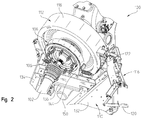
FIG. 2 is partial schematic perspective view of a drive system. -
FIG. 3 is a partial cross-sectional view of a drive system -
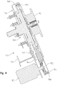
FIG. 4 is a cross-sectional view of an idler system. -
FIG. 5 is an exploded perspective view of an idler system. -
FIG. 6 is a fluid control circuit operatively connected to a motor and to a first and a second hydraulic cylinder. -
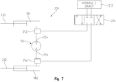
FIG. 7 illustrates another embodiment of a fluid control circuit. -
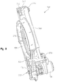
FIG. 8 illustrates a perspective view of another embodiment of an idler system. -
FIG. 9 illustrates another embodiment of a fluid control circuit. - For the purposes of promoting an understanding of the principles of the disclosure, reference will now be made to the embodiments described herein and illustrated in the drawings with specific language used to describe the same. It will nevertheless be understood that no limitation of the scope of the disclosure is intended. Such alterations and further modifications of the illustrated apparatus, assemblies, devices and methods, and such further applications of the principles of the disclosure as illustrated herein, are contemplated as would normally occur to one skilled in the art to which the disclosure relates.
- Referring now to
FIG. 1 , a largerectangular baler 10 includes amain frame 12 supported onwheels 14 for being towed over the ground by a tractor (not shown) coupled to a forward end of adraft tongue 16, which is fixed to a forward end of theframe 12. A longitudinally extending balingchamber 18, of rectangular or square cross-section, is supported centrally on theframe 12 at an elevation above the sets ofwheels 14. - A
plunger head 20 is mounted in a forward section of thechamber 18 for being reciprocated through the action of a toggle linkage defined by a pair of transversely spacedfirst links 24 and a second link or crankarm 26. Thelinks pivotal connection 28, with the pair offirst links 24 being pivotally coupled to theplunger head 20 atrespective pins 30, and with thesecond link 26 being coupled to theframe 12, as at apin 32. A hydraulic plungerhead drive cylinder 34 is provided for toggling thelinks pin 36, to a location of thelink 26. Thelink 26 is between thepivotal connections frame 12, as atpivot pin 38. When thedrive cylinder 34 is fully retracted, as shown inFIG. 1 , theplunger head 20 is fully extended to the rear, with thepins chamber 18. Extension of thecylinder 34 will cause thelink 26 to be pivoted upwardly about thepin 32 resulting in theplunger head 20 being retracted to the extent that it uncovers acrop material inlet 40 extending entirely across a region located just in front of a stationary knife (not shown) provided across aforward end 42 of a bottom wall orfloor 44 of the balingchamber 18. - The baling
chamber 18 includes afront section 46 of fixed cross section which is joined to arear section 48, of variable cross section, having opposite side panels which are respectively mounted for swinging horizontally about vertical hinges (not shown) provided at their forward ends. A twine tying arrangement (not shown) is provided for wrapping and tying multiple loops of twine about a completed bale. Aneedle yoke arrangement 50, includingopposite arms 52, is joined by across tube 54. Theneedle yoke arrangement 50 is mounted for vertical pivotal movement about a horizontal transverse axis defined bypivotal connections 56 that connect respective ends of thearms 52 to opposite side locations of rear regions of the fixed front balingchamber section 46. A plurality of curved, twine delivery needles, equal in number to the knotter drive gears, are respectively fixed to transversely spaced locations of thecross tube 54. A crank arm is provided at each of opposite ends of the knotter shaft and is pivotally connected between each crank arm and acoupler 58 fixed to eachneedle yoke arm 52, at a location close to thepivotal connection 56, is a connecting rod. - The bale tying cycle is initiated by a bale length sensor arrangement including a
toothed metering wheel 60 mounted on ashaft 62 extending horizontally across and being rotatably mounted to the top of the balingchamber 18. Themetering wheel 60 has a toothed periphery which extends into the balingchamber 18 and is contacted by a forming bale so as to be rotated as the bale grows in length. The rotation of themetering wheel 60 is sensed and converted into a signal representing bale length, with a control signal being sent to initiate the tying cycle when the forming bale reaches a length corresponding to a desired bale length. - The
machine 10 includes a feed duct orchute 64 having an openforward end section 66, disposed for receiving crop from a pick-uparrangement 68. Thechute 64 is curved upwardly and rearwardly from the forward end section to a near vertical rear end located for delivering crop through the balingchamber inlet 40. The pick-uparrangement 68 includes a rotary tine pick-up 70, including a drive rotor or shaft, and a pair ofstub augers 72 following the pick-up 70 for centering crop to the width of the balingchamber 18. Theduct 64 defines a chamber into which crop material delivered by the pick-uparrangement 68 is fed by apacker fork arrangement 74. Upon the material being compressed to a pre-selected density within the pre-charge chamber, astuffer arrangement 76 engages a pre-compressed charge of crop material, sometimes called a flake or slice, and sweeps it from the pre-charge chamber and into the balingchamber 18, by way of the balingchamber inlet 40. - A retaining
fork arrangement 80 includes a plurality of transversely spaced, hook-shaped retainer tines fixed at transversely spaced locations along a shaft of thearrangement 80. A density sensor, not shown, determines the density of the compressed crop. Once the compressed crop is determined to have a sufficient density, the retainingfork arrangement 80 moves from a retaining position to a release position, which allows the bale being formed and to move toward therear section 48. - The
draft tongue 16 includes adrive connector 82 which is configured to drive the above described systems and subsytems for forming bales, tying bales, and moving the formed bales into and out of the balingchamber 18. Thedraft tongue 16 includes aremovable housing 84 which provides a cover for aprimary drive system 100. Thedrive system 100, as further illustrated inFIG. 2 andFIG. 3 , is illustrated without thehousing 84. - The
drive system 100 includes adrive shaft 102 having a first end coupled to thedrive connector 82 by a first u-joint (not shown). A second end of thedrive shaft 102 is coupled to asecond u-joint 106. Operatively connected to the u-joint 106 is a torque limitingclutch assembly 108 which is illustrated schematically, but which is configured to disengage thedrive connector 84 from ahub 110 to which theclutch assembly 108 is connected. Thetorque assembly 108 includes at least two parts which rotate together, but which either slip or become disengaged should thehub 110 experience a predetermined amount of excessive torque. Thetorque assembly 108 acts a torque limiting device configured to reduce or prevent damage to thedrive system 100 when experiencing excessive loads, which either build up over time or which are instantaneously generated. - The
hub 110 is fixedly coupled to aflywheel 112, which in turn is fixedly coupled to adrive shaft 114. Thedrive shaft 114 is operatively connected to the above described systems and subsytems for forming bales, tying bales, and moving the formed bales into and out of the balingchamber 18. During operation of the various systems and subsystems, the flywheel experiences sufficient angular momentum to develop several thousands of pounds of horsepower, which in general terms, is a large amount of torque. Consequently, when the flywheel needs to be slowed and stopped from rotation, abrake apparatus 116, which disposed adjacently to anexterior surface 118 of theflywheel 112, is used to brake theflywheel 112. SeeFIG. 2 . Thebrake apparatus 116 includes abrake handle 120 which disposed at a location accessible to an operator outside thehousing 84. Movement of the brake handle 120 moves abrake pad device 122 into and out of engagement with thesurface 118 of theflywheel 112. - A
frame portion 130 of theframe 12, which is generally covered by thehousing 84 during operation of thebaler 10, is configured to support thedrive system 100 including thebrake apparatus 116. Theframe portion 130 includes afirst support member 132 and asecond support member 134 to which asupport bracket 136 is coupled. Thesupport bracket 136 extends from thefirst support member 132 to thesecond support member 134. Thebracket 136 is configured to provide support for anidler system 140 illustrated inFIGS. 2 ,3 ,4 , and5 . - The
idler system 140, or jog drive system, is an alternative or secondary drive system, in addition to theprimary drive system 100 which includes thedrive connector 82 which is coupled to the PTO or some other external drive system. Theidler system 140 is configured to move or adjust the location of the various system components including those described in the above described systems and subsystems for forming bales, tying bales, and moving the formed bales, to repair, maintain, or make adjustments to these and other performance systems of the work machine. Theidler system 140, therefore, is configured to move thehub 110, theflywheel 112, and thedrive shaft 114 in both a clockwise direction and a counter clockwise direction around alongitudinal axis 142 of thedrive shaft 114 to repair, adjust, or maintain the baler performance systems. - As illustrated in
FIG. 4 , theidler system 140 is operatively connected to thebracket 136 for support by theinternal frame 130. Theidler system 140 includes abase 144, which is rigidly coupled to thebracket 136 by one ormore connectors 146, and which support amotor 150. Themotor 150 is fixedly coupled to thebase 144 and includes anoutput drive shaft 152 which extends through thebase 144 and to which afirst pulley wheel 154 is operatively connected. Thebase 144, in one embodiment, is formed a sheet steel, and includes a "teardrop" shaped planar profile which defines anaperture 156 through which theclutch assembly 108 extends. In one embodiment, themotor 150 is a hydraulic motor having first and second ports (not shown) each of which are coupled to a hydraulic system configured to supply a flow of pressurized fluid to drive thedrive shaft 152 directionally or rotationally in a first direction and a second direction depending on the direction of fluid flow. SeeFIG. 5 , discussed later, for a fluid circuit. In another embodiment, themotor 150 is a pneumatic pump coupled to a pneumatic system and configured to rotate thedrive shaft 152 in either a first or second direction. In still another embodiment, themotor 150 is an electric motor coupled to an electric system and configured to rotate thedrive shaft 152 in either a first or second direction. - A
second pulley wheel 158 is disposed adjacently to theaperture 156 and is fixedly coupled to theclutch assembly 108 and thehub 110. As illustrated inFIG. 5 , thesecond pulley 158 includes a plurality ofapertures 160 which align withcorresponding apertures 162 of theclutch assembly 108 andapertures 164 of thehub 110. Connectors (not shown) are received by each of theapertures second pulley 158 to theclutch assembly 108 and to thehub 110 such that rotation of thedrive shaft 102 moves thepulley 158 and rotational movement of thesecond pulley 158 moves both theclutch assembly 108 and thehub 110. - In the illustrated embodiment, both the
first pulley 154 and thesecond pulley 158 are double-V pulleys configured to receive a double-V belt 166. In other embodiments, other types of pulleys and other types of belts are used. Consequently, rotation of theclutch assembly 108 orhub 110 driven by thedrive shaft 102 rotates thesecond pulley 158 which rotates thefirst pulley 154 and therefore theshaft 152 of themotor 150. Likewise, rotation of theshaft 152 by themotor 150 moves thefirst pulley 154 which in turn moves thesecond pulley 158 and thehub 110 which moves the various performance systems. Theclutch assembly 108 need not disengage when themotor 150 drives thebelt 166. In this event, thedrive shaft 102 rotates as well as the tractor shaft. The tractor allows rotation with some drag. Ashield 168, seen inFIGS. 4 and5 , is operatively connected to thebase 144, and partially covers or surrounds a portion of the v-belt 166 to provide a barrier between external unwanted forces or impacts and thebelt 166. - As best seen in
FIG. 5 , theshield 168 extends just past a midline of theaperture 156 to leave a portion of thebelt 166 exposed. Anidler apparatus 170, also described herein as a belt tensioner system, disposed adjacently to thebelt 166, includes afirst idler mechanism 172 and asecond idler mechanism 174. Theidler apparatus 170 is configured to apply a force or pressure to tension thebelt 166 at a first location 176 and at asecond location 178. The force is applied respectively by a firstidler arm device 180 and a secondidler arm device 182. Each of theidler arm devices locations 176 and 178 through the application of a force provided respectively by afirst actuator 184 and asecond actuator 186. In one embodiment, each of theactuators input port 185 and aninput port 187. In another embodiment, theactuators actuators idler apparatus 170 is illustrated as including afirst idler mechanism 172 and a second idler mechanism, in another embodiment theidler apparatus 170 includes a single idler mechanism. - As depicted in
FIG. 5 , each of thecylinders idler arm support bracket 136 or other frame (not shown), such that movement of the cylinder rods moves each of thearms axis axis arms belt 166 whereby an idler pulley 196 andidler pulley 198 apply tension respectively tolocations 176 and 178. Abias element 200, for instance a coil spring, is coupled to a support bracket of the frame at one end. The other end of thespring 200 is operatively connected to thearm 188. Asecond bias element 202, for instance a spring, is coupled to the support bracket or frame at one end and the other end of thespring 202 is operatively connected to thearm 190. Thehydraulic cylinders belt 166 with movement of the piston rods. Thehydraulic cylinders idler pulleys 196 and 198 to move away from thebelt 166 in response to the previously developed spring tension of thesprings -
FIG. 6 illustrates afluid control circuit 210 operatively connected to themotor 150 and to thehydraulic cylinders hydraulic source 212 is operatively connected tovalve 214 which is configured to provide a flow of fluid to and from themotor 150 over afirst fluid line 216, or conduit, and asecond fluid line 218, or conduit. First and second fluid connectors operatively couple the hydraulic source tofirst fluid line 216 and thesecond fluid line 218 through thevalve 214. Acontroller 219 is operatively connected to thehydraulic source 212 and to thevalve 214 to control the fluid delivered by thehydraulic source 212 and the direction of fluid flow through thevalve 214 and to and from thehydraulic source 212. In one embodiment, thevalve 214 is a four (4) way, three (3) position valve, which is configured to move the fluid in either direction along thefirst fluid line 216 and in either direction along thesecond fluid line 218. Themotor 150, therefore, is responsive to the direction of the flow of fluid through themotor 150, such that thedrive shaft 152 moves bi-directionally depending on the direction of the flow of fluid. - Each of the
cylinders ports valve 220 and avalve 222. Thefluid line 216 is operatively connected to thevalve 220 and to theport 185 of thecylinder 184 through thevalve 220. Thevalve 220 is also coupled to themotor 150 at aport 224. Thefluid line 218 is operatively connected to thevalve 222 and to theport 187 of the through thevalve 222. Thevalve 222 is also coupled to themotor 150 at aport 226. In different embodiments, each ofvalves lines circuit 210, including the hydraulic action of thecylinders valves controller 219 to achieve the desired performance and/or timing of thecircuit 210. - Each of the
cylinders respective piston rods piston rods arms cylinders - The
controller 219, in one embodiment includes a user control device configured to adjust the direction of the flow of fluid through themotor 224 such that the direction of rotation of thehub 110 ofFIG. 5 is moved about a central axis thereof in afirst direction 240 and asecond direction 242. Thecontroller 219, in different embodiments includes one or more of, mechanical adjustment devices, electronic adjustment devices, graphical user interface screens, electronic displays, and other known controllers. Each of the adjustment devices is configured to control the direction of the rotation of thehub 110. In one or more embodiments, the speed of rotation of thehub 110 is also controllable. In addition to the adjustment devices, in these and other embodiments, thecontroller 219 includes an electronic controller configured to control the flow of fluid in response to an input provided by the operator of the baler, either through devices located at the baler or located at a tractor or other vehicle pulling the baler. The electronic controller, in different embodiments, includes a microcontroller, a microprocessor, dedicated circuitry, or software controlled circuitry configured to provide the directional control of thehub 110 in response to a user input. - In operation and in response to a user input, a fluid from the
hydraulic source 212 moves along thefluid line 216, from thevalve 214 and toward thevalve 220. This fluid flow actuates thecylinder 184, which through the action of therod 230, moves the idler pulley 196 into contact with thebelt 166. The application of the idler pulley 196 applies a tension so thebelt 166 at the first location 176 as previously described. The fluid continues along the flow path through themotor 150 thereby rotating thepulley 154 in thedirection 240. The fluid continues along a flow path from themotor 150 through thevalve 222, thefluid line 218, to thevalve 214 and to the hydraulic source. - To move the
hub 110 in thesecond direction 242, the flow of fluid through the fluid circuit is reversed, such that fluid flow moves from thehydraulic source 212, through thevalve 214, along thefluid line 218, and through thevalve 222. The fluid flow actuates thecylinder 186 to move therod 232 and theidler pulley 198 into contact with thebelt 166. The application of theidler pulley 198 applies a tension to thebelt 166 at thesecond location 178 as previously described. The fluid flow continues through theport 226, themotor 150, through theport 224, through thevalve 220 along thefluid line 216, through thevalve 214 and back to thesource 212. - Both the
hydraulic motor 150 and thehydraulic cylinders fluid circuit 210. The belt tension is appropriately controlled depending on the directions ofrotation motor 150. The belt tension either increases or decreases appropriately with the direction and torque output of themotor 150. The belt tension is applied proportionally to the torque output of themotor 150 to reduce or substantially prevent belt slippage. Theidler system 140, therefore, applies back side tension to the belt with bi-directional capabilities. - The application of the idler system to the belt, or the tensioning force applied, is proportional to the motor torque, such that the tensioning force increases under increased torque of the motor to reduce or substantially prevent belt slippage. When the motor is not producing any drive force, the idler system does not apply a tensioning force thereby disengaging the idler pulley 196 and the
idler pulley 198 from thebelt 166. The tensioning force is automatically applied to the belt in proportion to the drive force provided by the motor and does not require an operator to select the amount of force to be applied to the belt, since the tensioning system automatically increases/decreases the tensioning force. When the motor is not producing any drive force, the tensioner disengages or does not apply a sufficient force to tension the belt. - The
controller 219, in different embodiments, is configured to control the operation of thevalves hydraulic cylinders valves respective control lines fluid lines valves pulleys 196 and 198 through the action of thecylinders valves valves controller 219 to sequence the flow, by flow rate or pressure, to engage thebelt 166 before themotor 150 begins to move in one of the first and the second directions. In this embodiment, the movement of thefirst pulley wheel 154 through actuation of themotor 150 drives thebelt 166 substantially immediately such that there is minimal lag between actuation of themotor 150 and movement of thesecond pulley wheel 158. In another embodiment, thecontroller 219 is replaced with a hydraulic controller including hydraulic control valves which are configured to provide the sequencing and the flow of fluid provided to themotor 150 and to thehydraulic cylinders -
FIG. 7 illustrates another embodiment of afluid control circuit 250 operatively connected to themotor 150 and to thehydraulic cylinders FIG. 6 , each of the hydraulic cylinders includesrespective piston rods hydraulic source 212 is operatively connected to thevalve 214 which is configured to provide a flow of fluid to and from themotor 150 over thefirst fluid line 216, or conduit, and thesecond fluid line 218, or conduit. In this embodiment, a firstpressure control valve 252 is operatively connected to theport 224 of themotor 150 and a secondpressure control valve 254 is operatively connected to theport 226 of themotor 150. Each of the first and secondpressure control valves hydraulic cylinders controller 219 ofFIG. 6 is not required. Each of the first and secondpressure control valves -
FIG. 8 illustrates a perspective view of another embodiment of anidler system 260. As described herein, themotor 150 and associatedpulley 154 are configured to drive thepulley 158 with thebelt 166. In this embodiment, however, theidler system 260 includes aframe 262 configured to support themotor 150 with respect to thepulley 158. Theframe 262, at afirst end 264, includes apin 266 configured to support one end of ahydraulic actuator 268. Another end of thehydraulic actuator 268 is operatively connected to amotor support 270 which is configured to adjustably support themotor 150 with respect to theframe 262. Actuation of thehydraulic actuator 268 adjusts themotor support 270 with respect to thepin 262. Consequently, a distance between acenter 272 of thepulley 154 is adjustable with respect to acenter 274 of thepulley 158. By actuating thehydraulic actuator 268, the distance between thecenter 272 and thecenter 274 is either increased or decreased to increase or to reduce the tension of thebelt 166. -
FIG. 9 illustrates another embodiment of afluid control circuit 280 operatively connected to themotor 150 of theidler system 260 ofFIG. 8 . As inFIG. 6 , thehydraulic source 212 is operatively connected to themotor 150 and the operation thereof is controlled by thecontroller 219. Avalve 282 is operatively connected to thecontroller 219 for movement of the valve from at least a first position to a second position to control themotor 150. In one embodiment, thevalve 282 is a selectable control valve configured to respond to one or more control signals provided by thecontroller 219. Theselectable control valve 282, in different embodiments, is located on a vehicle, such as a tractor, or on a work machine such as a bailer. A lowpressure return line 284 couples thevalve 282 to thesource 212 and ahigh pressure line 286 couples thevalve 282 to thesource 212. Additionally, thehigh pressure line 286 is operatively connected to apressure control valve 288. In different embodiments, thepressure control valve 288 includes a pressure relief valve or an internally piloted sequence valve. Acontrol line 290 operatively connects thecontroller 219 to thevalve 288 to provide control signals to thevalve 288. Anoutput 292 of thevalve 288 is coupled to thecylinder 268. Upon receiving an actuation signal from thecontroller 219, thevalve 288 moves themotor 150 from a first position to a second position to thereby adjust the tension of thebelt 166 ofFIG. 8 . - While exemplary embodiments incorporating the principles of the present disclosure have been disclosed herein, the present disclosure is not limited to the disclosed embodiments. Instead, this application is intended to cover any variations, uses, or adaptations of the disclosure using its general principles. Therefore, this application is intended to cover such departures from the present disclosure as come within known or customary practice in the art to which this disclosure pertains.
Claims (15)
- A drive system (100) for an agricultural work machine, the drive system (100) configured to drive a performance system for performing a crop preparation or handling operation, the drive system (100) comprising:a motor (150) configured to produce a drive force; anda tensioner system (170) operatively connected to the motor (150), wherein a directional movement of the motor (150) adjusts the application of at least one force applied in the drive system (100) to adjust a tension thereof.
- The drive system (100) of claim 1 wherein the tensioner system (170) adjusts the application of the at least one force applied in the drive system (100) proportionally to the magnitude of the motor drive force.
- The drive system (100) of claim 1 or 2 wherein the tensioner system (170) includes a first tensioner (172), the first tensioner (172) being configured to apply a first force when the motor (150) moves in a first direction, the first force configured to adjust the application of the at least one force applied in the drive system (100) to adjust a tension thereof.
- The drive system (100) of one of the claims 1 to 3 wherein the tensioner system (170) includes a second tensioner (174), the second tensioner (174) being configured to apply a second force when the motor (150) moves in a second direction.
- The drive system (100) of one of the claims 1 to 4 further comprising a force transfer system configured to transfer the drive force from the motor (150), the force transfer system including a first wheel driven by a shaft of the motor (154) and a second wheel (158) driven by a belt (166), wherein the second wheel (158) is operatively connected to the first wheel (154) by the belt.
- The drive system (100) of claim 5 wherein the first force and second force are configured to be applied to the belt (166) to increase the tension of the belt (166).
- The drive system (100) of claim 5 or 6 wherein the first force is configured to be applied to the belt (166) during a first direction of movement of the belt (166) and the second force is configured to be applied to the belt (166) during a second direction of movement of the belt (166).
- The drive system (100) of one of the claims 5 to 7 further comprising a first bias element (172) and a second bias element (174), wherein the first force is applied to the belt (166) in a direction opposite a first bias provided by the first bias element (172), and the second force is applied to the belt (166) in a direction opposite a second bias provided by the second bias element (174).
- The drive system (100) of one of the claims 1 to 8 wherein the motor (150) includes a fluid motor configured to be driven by a flow of fluid from a fluid pump (212), the fluid pump (212) is operatively connected to the fluid motor (150) through a first fluid line (216) and a second fluid line (218), and the fluid pump (212) is configured to move fluid through the first fluid line (216), the fluid motor (150), and the second fluid line (218) in a first direction and a second direction opposite the first direction.
- The drive system (100) of claim 9 wherein the first tensioner (172) includes a first hydraulic actuator (184) operatively connected to the first fluid line (216) between the fluid pump (212) and the fluid motor (150), and the second tensioner (174) includes a second hydraulic actuator (186) operatively connected to the second fluid line (218) between the fluid pump (212) and the fluid motor (150).
- The drive system (100) of claim 9 or 10 further comprising a first flow control valve (252) operatively connected to the first fluid line (216) between the fluid motor (150) and the first hydraulic actuator (184), and a second flow control valve (254) operatively connected to the second fluid line (218) between the fluid motor (150) and the second hydraulic actuator (186).
- The drive system (100) of one of the claims 5 to 11 wherein the tensioner system (170) proportionally tensions the belt (166) based upon the output of the hydraulic motor (150).
- The drive system (100) of one of the claims 9 to 12 wherein fluid flow from a first connector of the hydraulic fluid pump (212) to the first hydraulic actuator (184) moves the hydraulic actuator (184) to tension the belt (166) at a first location and to move an output of the hydraulic motor (150) in a first direction and wherein fluid flow from a second connector of the hydraulic fluid pump (212) to the second hydraulic actuator (186) moves the hydraulic actuator (186) to tension the belt (166) at a second location and to move the output of the hydraulic motor (150) in a second direction.
- A method of providing a crop preparation or handling operation with a performance system of an agricultural work machine driven by a primary power source, the method comprising:providing a primary drive system (100) operatively connected to a primary power source and configured to drive the performance system for the crop preparation or handling operation;providing a secondary drive system (140) operatively connected to the primary drive system (100), wherein the secondary drive system (140) includes a fluid driven motor (150) having a drive shaft (152) providing a torque, the fluid driven motor (150) operatively connected to a belt (166) configured to adjust a condition of the primary drive system (100); andautomatically adjusting a tension of the belt (166) proportionally in response to the torque provided by the drive shaft (152) of the motor (150).
- The method of claim 14 further comprising increasing the tension of belt (166) proportionally to an increase in the torque provided by the drive shaft (152) of the motor (155), and decreasing the tension of belt (166) proportionally to a decrease in the torque provided by the drive shaft (152) of the motor (150).
Applications Claiming Priority (1)
| Application Number | Priority Date | Filing Date | Title |
|---|---|---|---|
| US14/685,805 US9528576B2 (en) | 2015-04-14 | 2015-04-14 | Drive system with hydraulic idler tensioner |
Publications (2)
| Publication Number | Publication Date |
|---|---|
| EP3081074A1 true EP3081074A1 (en) | 2016-10-19 |
| EP3081074B1 EP3081074B1 (en) | 2018-06-27 |
Family
ID=55754146
Family Applications (1)
| Application Number | Title | Priority Date | Filing Date |
|---|---|---|---|
| EP16165104.7A Active EP3081074B1 (en) | 2015-04-14 | 2016-04-13 | Drive system and method with such |
Country Status (4)
| Country | Link |
|---|---|
| US (2) | US9528576B2 (en) |
| EP (1) | EP3081074B1 (en) |
| BR (1) | BR102016008079A2 (en) |
| RU (1) | RU2016112113A (en) |
Families Citing this family (12)
| Publication number | Priority date | Publication date | Assignee | Title |
|---|---|---|---|---|
| US9759293B2 (en) * | 2014-10-21 | 2017-09-12 | Litens Automotive Partnership | Endless drive arrangement and improved two-armed tensioning system for same |
| ES2903427T3 (en) | 2015-02-06 | 2022-04-01 | Litens Automotive Inc | Endless drive arrangement for hybrid vehicles using a two-arm tensioner with non-orbiting arms |
| WO2017205976A1 (en) * | 2016-05-30 | 2017-12-07 | Litens Automotive Partnership | Endless drive arrangement and tensioning system for same |
| CN109922656A (en) | 2016-08-31 | 2019-06-21 | 维米尔制造公司 | Continuous circular baler and the improved method for forming round bale |
| US11261945B1 (en) * | 2017-06-22 | 2022-03-01 | Board Of Trustees Of The University Of Alabama, For And On Behalf Of The University Of Alabama In Huntsville | Coupling system for reducing fatigue and dynamic amplification of loads in objects |
| DE102017217645A1 (en) * | 2017-10-05 | 2019-04-11 | Bayerische Motoren Werke Aktiengesellschaft | Belt tensioner |
| US10806092B2 (en) | 2018-07-06 | 2020-10-20 | Deere & Company | Remote control system |
| CN109458365B (en) * | 2018-12-24 | 2024-02-02 | 江苏徐工工程机械研究院有限公司 | Construction machinery hydraulic systems and construction machinery |
| US12128420B2 (en) | 2021-04-13 | 2024-10-29 | Alamo Group Inc. | Work machine with belt tensioning system and method |
| CN113864413B (en) * | 2021-10-28 | 2023-03-17 | 南昌矿机集团股份有限公司 | Tensioning device and method for transmission belt of crusher |
| DE102022113276A1 (en) * | 2022-05-25 | 2023-11-30 | Usines Claas France S.A.S | Agricultural baler with a tensioning device for a traction drive |
| US20240344595A1 (en) * | 2023-04-11 | 2024-10-17 | Fca Us Llc | Dual arm tensioner with hydraulic strut |
Citations (7)
| Publication number | Priority date | Publication date | Assignee | Title |
|---|---|---|---|---|
| US4893883A (en) * | 1988-03-02 | 1990-01-16 | Caterpillar Inc. | Belt tension control system |
| US5176581A (en) * | 1991-06-06 | 1993-01-05 | Kumm Industries, Inc. | Self-energized controllable belt tensioner |
| US5334106A (en) * | 1993-05-06 | 1994-08-02 | Caterpillar Inc. | Hydraulic recoil and belt tension control system |
| EP1340421A1 (en) * | 2002-02-28 | 2003-09-03 | Deere & Company | Rectangular baler |
| EP1974601A1 (en) * | 2007-03-31 | 2008-10-01 | Maschinenfabrik Bernhard Krone GmbH | Large baling press |
| EP2193707A1 (en) * | 2008-10-31 | 2010-06-09 | Deere & Company | Work machine |
| WO2014159895A1 (en) * | 2013-03-13 | 2014-10-02 | Husqvarna Ab | Slip controlling belt tension system |
Family Cites Families (78)
| Publication number | Priority date | Publication date | Assignee | Title |
|---|---|---|---|---|
| US2082634A (en) * | 1936-02-01 | 1937-06-01 | Cameron Machine Co | Electric control system |
| US2356567A (en) * | 1941-10-16 | 1944-08-22 | Gen Electric | Control system |
| US2639623A (en) * | 1950-03-29 | 1953-05-26 | Harry S Ausherman | Belt tightener and slack adjuster |
| US2726364A (en) * | 1952-04-12 | 1955-12-06 | Nolan Company | Overload-controlling mechanism for electric motor-driven apparatus |
| US2766417A (en) * | 1952-08-09 | 1956-10-09 | Nolan Company | Belt drive actuated motor controlling switch mechanism |
| GB773398A (en) * | 1954-10-20 | 1957-04-24 | Stothert & Pitt Ltd | Improvements in and relating to vibratory rollers |
| US3012520A (en) * | 1959-11-18 | 1961-12-12 | Guy A Curtis | Reversible driving mechanism with automatic stop |
| US3184374A (en) * | 1962-09-24 | 1965-05-18 | Black Clawson Co | Apparatus for oscillating a traveling web in paper machinery |
| US3403474A (en) * | 1966-07-11 | 1968-10-01 | Spasoff John | Actuator mechanism for movable closure |
| US3575058A (en) * | 1968-08-20 | 1971-04-13 | Excelermatic | Motion transmission drive |
| US3640145A (en) * | 1970-05-21 | 1972-02-08 | Excelermatic | Motion transmission drive |
| USRE27861E (en) * | 1972-02-16 | 1974-01-01 | Motion transmission devi cp | |
| US3817114A (en) * | 1973-01-29 | 1974-06-18 | Case Co J I | Chain tightener for endless chain |
| US3887026A (en) * | 1973-09-24 | 1975-06-03 | Ford Motor Co | Motor vehicle power steering device |
| US4007826A (en) * | 1976-04-02 | 1977-02-15 | Stephens-Adamson, Inc. | Dual pressure take-up apparatus and system for dual belt conveyor-elevator |
| US4564098A (en) * | 1979-06-21 | 1986-01-14 | Hormann Kg | Drive assembly for door operator |
| US4759256A (en) * | 1984-04-16 | 1988-07-26 | Nl Industries, Inc. | Tensioner recoil control apparatus |
| US4699097A (en) * | 1984-08-31 | 1987-10-13 | Mazda Motor Corporation | Means for suppressing engine output torque fluctuations |
| US4758310A (en) * | 1986-04-08 | 1988-07-19 | Miller Ray R | Belt and drum-type pressing apparatus |
| US4877487A (en) * | 1986-04-08 | 1989-10-31 | Miller Ray R | Belt and drum-type press with supplemental nip loading means |
| US4758208A (en) * | 1987-07-13 | 1988-07-19 | General Motors Corporation | Automatic belt tensioner for vehicle combined starter-generator |
| JPH0718349B2 (en) * | 1989-02-09 | 1995-03-01 | 本田技研工業株式会社 | Winding transmission device for internal combustion engine |
| US5132604A (en) * | 1989-04-04 | 1992-07-21 | Honda Giken Kogyo Kabushiki Kaisha | Engine starter and electric generator system |
| JPH0319157U (en) * | 1989-07-05 | 1991-02-25 | ||
| DE4213038C1 (en) * | 1992-04-21 | 1993-07-15 | Dr.Ing.H.C. F. Porsche Ag, 7000 Stuttgart, De | |
| ZA94606B (en) * | 1993-02-04 | 1994-07-22 | Intechn Technologies C C | Turnstyle control mechanism |
| US5444969A (en) | 1993-07-12 | 1995-08-29 | New Holland North America, Inc. | Round baler apparatus for monitoring bale shape |
| US5752891A (en) * | 1995-03-20 | 1998-05-19 | Ford Global Technologies, Inc. | Electronically controlled accessory drive system for the automotive engine |
| US5997423A (en) * | 1996-11-20 | 1999-12-07 | Lg Industrial Systems Co., Ltd. | Apparatus for controlling chain tension |
| DE19733263A1 (en) * | 1997-08-01 | 1999-02-04 | Sipra Patent Beteiligung | Thread delivery device on a textile machine and belt tensioning device therefor |
| US6478701B1 (en) * | 1997-11-13 | 2002-11-12 | Koyo Seiko Co., Ltd. | Belt type nonstage transmission system |
| DE19926612A1 (en) * | 1999-06-11 | 2000-12-14 | Schaeffler Waelzlager Ohg | Belt drive of an internal combustion engine |
| DE19926615A1 (en) * | 1999-06-11 | 2000-12-14 | Schaeffler Waelzlager Ohg | Tensioning device for traction devices such as belts or chains |
| JP4634565B2 (en) * | 2000-03-09 | 2011-02-16 | 東北リコー株式会社 | Printing device |
| US7032349B2 (en) * | 2000-04-27 | 2006-04-25 | Atoma International Corp. | Coreless motor door closure system for motor vehicles |
| WO2002029281A1 (en) * | 2000-10-03 | 2002-04-11 | The Gates Corporation | Motor/generator and accessory belt drive system |
| DE60116888T2 (en) * | 2000-10-03 | 2006-10-26 | The Gates Corp., Denver | DOUBLE, LINEAR BELT TENSION |
| US6716124B2 (en) * | 2000-11-29 | 2004-04-06 | Borgwarner Inc. | Hydraulic tensioner with improved pressure relief valve reactive to peak operating loads |
| US20020123401A1 (en) * | 2001-03-02 | 2002-09-05 | Henry Rassem Ragheb | Combination starter-generator |
| TWI225539B (en) * | 2001-11-06 | 2004-12-21 | Gates Corp | Travel limited linear belt tensioner |
| US6609985B2 (en) * | 2001-11-07 | 2003-08-26 | Borgwarner Inc. | Tensioner with vibrational damping |
| US6689001B2 (en) * | 2001-12-12 | 2004-02-10 | Dayco Products, Llc | Adaptive belt tensioner system for control of reversible torque load pulley |
| US6652401B2 (en) * | 2002-02-11 | 2003-11-25 | The Gates Corporation | Method of tuning a belt drive system |
| US6651416B2 (en) | 2002-02-28 | 2003-11-25 | Deere & Company | Large rectangular baler having hydraulically powered functions, and control system therefor |
| US6852050B2 (en) * | 2002-04-17 | 2005-02-08 | Carrier Commercial Refrigeration, Inc. | Lateral sensor for conveyor belt |
| US6726532B2 (en) * | 2002-07-24 | 2004-04-27 | Taiwan Semiconductor Manufacturing Co., Ltd | Belt tensioning assembly for CMP apparatus |
| US6960145B2 (en) * | 2002-08-30 | 2005-11-01 | Trw, Inc. | Belt tensioner for electric power steering unit |
| CN100445599C (en) * | 2002-12-16 | 2008-12-24 | 盖茨公司 | Active tensioner, system and method for controlling belt tension |
| DE20311436U1 (en) * | 2003-07-24 | 2003-09-18 | DBT Automation GmbH, 44534 Lünen | Device for detecting scratch chain tension states |
| JP2005195059A (en) * | 2004-01-05 | 2005-07-21 | Bando Chem Ind Ltd | Auto tensioner control device |
| US6834631B1 (en) * | 2004-03-08 | 2004-12-28 | Dana Corporation | Method of determining transition from starter to alternator function by monitoring belt tension or tensioner position |
| AT501482B8 (en) * | 2004-05-26 | 2007-02-15 | Gfm Beteiligungs & Man Gmbh | DEVICE FOR INTERMITTENTLY DRIVING A SPINDLE FOR A WORKPIECE BRACKET, ESPECIALLY A FORGING MACHINE |
| DE102004028017A1 (en) * | 2004-06-08 | 2005-12-29 | Bayerische Motoren Werke Ag | traction mechanism |
| ITPI20040077A1 (en) * | 2004-10-14 | 2005-01-14 | Univ Pisa | GEAR MOTOR MECHANISM WITH VARIABLE AND QUICKLY CONTROLLABLE RIGIDITY |
| US7479078B2 (en) * | 2004-11-17 | 2009-01-20 | Dayco Products, Llc | Belt tensioner system |
| DE102005017038A1 (en) * | 2005-04-13 | 2006-10-19 | Schaeffler Kg | Traction drive, in particular belt drive for ancillaries of an internal combustion engine |
| GB2426561B (en) * | 2005-05-24 | 2010-07-28 | Ford Global Tech Llc | Chain tensioner |
| BE1016375A5 (en) * | 2005-06-06 | 2006-09-05 | Dredging Int | Spud for cutter suction dredger ship, has tensioned wires extending between ship and stud pole for absorbing forces from stud carriage |
| US7494434B2 (en) * | 2005-06-15 | 2009-02-24 | Gm Global Technology Operations, Inc. | Belt alternator starter accessory drive with dual tensioner |
| US7553248B2 (en) * | 2005-09-21 | 2009-06-30 | Exmark Manufacturing Company, Incorporated | Belt drive system incorporating fixed brake member |
| US7322895B2 (en) * | 2005-11-23 | 2008-01-29 | Gm Global Technology Operations, Inc. | Automotive accessory drive system |
| WO2007079447A2 (en) * | 2005-12-30 | 2007-07-12 | Tibion Corporation | Linear actuator |
| US20070155558A1 (en) * | 2005-12-30 | 2007-07-05 | Horst Robert W | Continuously variable transmission |
| US7648436B2 (en) * | 2005-12-30 | 2010-01-19 | Tibion Corporation | Rotary actuator |
| US7815533B2 (en) * | 2006-09-18 | 2010-10-19 | Ford Global Technologies | Camshaft drive system for internal combustion engine |
| DE602006012706D1 (en) | 2006-12-22 | 2010-04-15 | Max Planck Gesellschaft | Method and apparatus for optical vernier spectroscopy |
| DE102008042201B4 (en) * | 2007-09-27 | 2023-12-21 | Baumüller Nürnberg GmbH | Electromotive tensioning mechanism and starting methodology for it |
| JP4707072B2 (en) * | 2008-05-23 | 2011-06-22 | 本田技研工業株式会社 | Power transmission device for vehicle |
| PL2248412T3 (en) | 2009-05-08 | 2012-11-30 | Deere & Co | Round baler |
| US8291687B2 (en) | 2009-07-31 | 2012-10-23 | Agco Corporation | Continuous round baler |
| US9133762B2 (en) * | 2009-09-18 | 2015-09-15 | GM Global Technology Operations LLC | Drive belt tensioner for motor generator unit |
| US20120152644A1 (en) * | 2010-12-20 | 2012-06-21 | Paul Harriman Kydd | Compliant, balanced belt or chain drive |
| DE102011003727A1 (en) | 2011-02-07 | 2012-08-09 | Deere & Company | Round baler with lateral guides for the press belt |
| US20120318589A1 (en) * | 2011-06-20 | 2012-12-20 | GM Global Technology Operations LLC | Belt tensioning assembly for an engine system having a motor-generator unit |
| WO2013033822A1 (en) * | 2011-09-05 | 2013-03-14 | Litens Automotive Partnership | Intelligent belt drive system and method |
| JP2013096471A (en) * | 2011-10-31 | 2013-05-20 | Tsubakimoto Chain Co | Hydraulic tensioner |
| KR101220915B1 (en) * | 2011-11-04 | 2013-02-14 | 주식회사 오토파워 | Speed control method with the activation function and torque compensator |
| JP2013204690A (en) * | 2012-03-28 | 2013-10-07 | Tsubakimoto Chain Co | Hydraulic tensioner |
-
2015
- 2015-04-14 US US14/685,805 patent/US9528576B2/en active Active
-
2016
- 2016-03-31 RU RU2016112113A patent/RU2016112113A/en not_active Application Discontinuation
- 2016-04-12 BR BR102016008079A patent/BR102016008079A2/en active Search and Examination
- 2016-04-13 EP EP16165104.7A patent/EP3081074B1/en active Active
- 2016-09-28 US US15/278,103 patent/US9995374B2/en active Active
Patent Citations (7)
| Publication number | Priority date | Publication date | Assignee | Title |
|---|---|---|---|---|
| US4893883A (en) * | 1988-03-02 | 1990-01-16 | Caterpillar Inc. | Belt tension control system |
| US5176581A (en) * | 1991-06-06 | 1993-01-05 | Kumm Industries, Inc. | Self-energized controllable belt tensioner |
| US5334106A (en) * | 1993-05-06 | 1994-08-02 | Caterpillar Inc. | Hydraulic recoil and belt tension control system |
| EP1340421A1 (en) * | 2002-02-28 | 2003-09-03 | Deere & Company | Rectangular baler |
| EP1974601A1 (en) * | 2007-03-31 | 2008-10-01 | Maschinenfabrik Bernhard Krone GmbH | Large baling press |
| EP2193707A1 (en) * | 2008-10-31 | 2010-06-09 | Deere & Company | Work machine |
| WO2014159895A1 (en) * | 2013-03-13 | 2014-10-02 | Husqvarna Ab | Slip controlling belt tension system |
Also Published As
| Publication number | Publication date |
|---|---|
| BR102016008079A2 (en) | 2016-11-08 |
| US20170016518A1 (en) | 2017-01-19 |
| US9995374B2 (en) | 2018-06-12 |
| US20160305514A1 (en) | 2016-10-20 |
| US9528576B2 (en) | 2016-12-27 |
| RU2016112113A (en) | 2017-10-06 |
| EP3081074B1 (en) | 2018-06-27 |
Similar Documents
| Publication | Publication Date | Title |
|---|---|---|
| US9995374B2 (en) | Drive system with hydraulic idler tensioner | |
| US6651416B2 (en) | Large rectangular baler having hydraulically powered functions, and control system therefor | |
| EP2735223B1 (en) | Self-propelled mower-conditioner | |
| US11700793B2 (en) | Baler rotor feeding apparatus | |
| US20180084723A1 (en) | Drive system of a utility vehicle | |
| EP3158852B1 (en) | Rotor feeder unit for agricultural machines | |
| AU2017260128B2 (en) | Conditioner unit | |
| US20080257570A1 (en) | Electronic draft control for semi-trailed implements | |
| EP3695705B1 (en) | Harvesting machine with crop throughput sensing system | |
| EP3912454A1 (en) | Roll conditioner adjustment system for an agricultural harvesting machine | |
| US10806092B2 (en) | Remote control system | |
| US6973779B2 (en) | Hydraulic power system for agricultural implement including flow-rate indicator | |
| WO2017116982A1 (en) | Variable speed drive for large square baler | |
| EP2353364B1 (en) | Agricultural harvesting pickup apparatus | |
| EP1600049A1 (en) | Kernel Cracking Assembly | |
| EP1340421A1 (en) | Rectangular baler | |
| CA1064264A (en) | Gathering unit control apparatus | |
| NL7905196A (en) | MOVABLE HARVESTER. | |
| EP4635290A1 (en) | A method of forming a bale by a baler, an agricultural system, and a baler | |
| CN105900544A (en) | Caterpillar band self-propelled bundling rotary cultivator | |
| EP4295667A1 (en) | Auxiliary pressure circuit for a round baler | |
| US20240049639A1 (en) | Actively variable swath gate position | |
| AU2003200756B2 (en) | Large rectangular baler having hydraulically powered functions, and control system therefor | |
| KR0120957B1 (en) | Combine for a tractor |
Legal Events
| Date | Code | Title | Description |
|---|---|---|---|
| PUAI | Public reference made under article 153(3) epc to a published international application that has entered the european phase |
Free format text: ORIGINAL CODE: 0009012 |
|
| AK | Designated contracting states |
Kind code of ref document: A1 Designated state(s): AL AT BE BG CH CY CZ DE DK EE ES FI FR GB GR HR HU IE IS IT LI LT LU LV MC MK MT NL NO PL PT RO RS SE SI SK SM TR |
|
| AX | Request for extension of the european patent |
Extension state: BA ME |
|
| STAA | Information on the status of an ep patent application or granted ep patent |
Free format text: STATUS: REQUEST FOR EXAMINATION WAS MADE |
|
| 17P | Request for examination filed |
Effective date: 20170419 |
|
| RBV | Designated contracting states (corrected) |
Designated state(s): AL AT BE BG CH CY CZ DE DK EE ES FI FR GB GR HR HU IE IS IT LI LT LU LV MC MK MT NL NO PL PT RO RS SE SI SK SM TR |
|
| STAA | Information on the status of an ep patent application or granted ep patent |
Free format text: STATUS: EXAMINATION IS IN PROGRESS |
|
| 17Q | First examination report despatched |
Effective date: 20170801 |
|
| GRAP | Despatch of communication of intention to grant a patent |
Free format text: ORIGINAL CODE: EPIDOSNIGR1 |
|
| STAA | Information on the status of an ep patent application or granted ep patent |
Free format text: STATUS: GRANT OF PATENT IS INTENDED |
|
| RIC1 | Information provided on ipc code assigned before grant |
Ipc: A01D 34/76 20060101ALI20180125BHEP Ipc: F16H 7/12 20060101ALI20180125BHEP Ipc: A01D 69/08 20060101ALI20180125BHEP Ipc: A01D 34/56 20060101ALI20180125BHEP Ipc: A01D 69/00 20060101ALI20180125BHEP Ipc: A01F 15/08 20060101AFI20180125BHEP Ipc: A01D 69/03 20060101ALI20180125BHEP Ipc: F16H 7/08 20060101ALI20180125BHEP Ipc: F16H 7/00 20060101ALI20180125BHEP |
|
| INTG | Intention to grant announced |
Effective date: 20180219 |
|
| GRAS | Grant fee paid |
Free format text: ORIGINAL CODE: EPIDOSNIGR3 |
|
| GRAA | (expected) grant |
Free format text: ORIGINAL CODE: 0009210 |
|
| STAA | Information on the status of an ep patent application or granted ep patent |
Free format text: STATUS: THE PATENT HAS BEEN GRANTED |
|
| AK | Designated contracting states |
Kind code of ref document: B1 Designated state(s): AL AT BE BG CH CY CZ DE DK EE ES FI FR GB GR HR HU IE IS IT LI LT LU LV MC MK MT NL NO PL PT RO RS SE SI SK SM TR |
|
| REG | Reference to a national code |
Ref country code: GB Ref legal event code: FG4D |
|
| REG | Reference to a national code |
Ref country code: AT Ref legal event code: REF Ref document number: 1011488 Country of ref document: AT Kind code of ref document: T Effective date: 20180715 |
|
| REG | Reference to a national code |
Ref country code: IE Ref legal event code: FG4D |
|
| REG | Reference to a national code |
Ref country code: DE Ref legal event code: R096 Ref document number: 602016003766 Country of ref document: DE |
|
| PG25 | Lapsed in a contracting state [announced via postgrant information from national office to epo] |
Ref country code: SE Free format text: LAPSE BECAUSE OF FAILURE TO SUBMIT A TRANSLATION OF THE DESCRIPTION OR TO PAY THE FEE WITHIN THE PRESCRIBED TIME-LIMIT Effective date: 20180627 Ref country code: LT Free format text: LAPSE BECAUSE OF FAILURE TO SUBMIT A TRANSLATION OF THE DESCRIPTION OR TO PAY THE FEE WITHIN THE PRESCRIBED TIME-LIMIT Effective date: 20180627 Ref country code: FI Free format text: LAPSE BECAUSE OF FAILURE TO SUBMIT A TRANSLATION OF THE DESCRIPTION OR TO PAY THE FEE WITHIN THE PRESCRIBED TIME-LIMIT Effective date: 20180627 Ref country code: NO Free format text: LAPSE BECAUSE OF FAILURE TO SUBMIT A TRANSLATION OF THE DESCRIPTION OR TO PAY THE FEE WITHIN THE PRESCRIBED TIME-LIMIT Effective date: 20180927 Ref country code: BG Free format text: LAPSE BECAUSE OF FAILURE TO SUBMIT A TRANSLATION OF THE DESCRIPTION OR TO PAY THE FEE WITHIN THE PRESCRIBED TIME-LIMIT Effective date: 20180927 |
|
| REG | Reference to a national code |
Ref country code: NL Ref legal event code: MP Effective date: 20180627 |
|
| REG | Reference to a national code |
Ref country code: LT Ref legal event code: MG4D |
|
| PG25 | Lapsed in a contracting state [announced via postgrant information from national office to epo] |
Ref country code: LV Free format text: LAPSE BECAUSE OF FAILURE TO SUBMIT A TRANSLATION OF THE DESCRIPTION OR TO PAY THE FEE WITHIN THE PRESCRIBED TIME-LIMIT Effective date: 20180627 Ref country code: RS Free format text: LAPSE BECAUSE OF FAILURE TO SUBMIT A TRANSLATION OF THE DESCRIPTION OR TO PAY THE FEE WITHIN THE PRESCRIBED TIME-LIMIT Effective date: 20180627 Ref country code: HR Free format text: LAPSE BECAUSE OF FAILURE TO SUBMIT A TRANSLATION OF THE DESCRIPTION OR TO PAY THE FEE WITHIN THE PRESCRIBED TIME-LIMIT Effective date: 20180627 Ref country code: GR Free format text: LAPSE BECAUSE OF FAILURE TO SUBMIT A TRANSLATION OF THE DESCRIPTION OR TO PAY THE FEE WITHIN THE PRESCRIBED TIME-LIMIT Effective date: 20180928 |
|
| REG | Reference to a national code |
Ref country code: AT Ref legal event code: MK05 Ref document number: 1011488 Country of ref document: AT Kind code of ref document: T Effective date: 20180627 |
|
| PG25 | Lapsed in a contracting state [announced via postgrant information from national office to epo] |
Ref country code: NL Free format text: LAPSE BECAUSE OF FAILURE TO SUBMIT A TRANSLATION OF THE DESCRIPTION OR TO PAY THE FEE WITHIN THE PRESCRIBED TIME-LIMIT Effective date: 20180627 |
|
| PG25 | Lapsed in a contracting state [announced via postgrant information from national office to epo] |
Ref country code: AT Free format text: LAPSE BECAUSE OF FAILURE TO SUBMIT A TRANSLATION OF THE DESCRIPTION OR TO PAY THE FEE WITHIN THE PRESCRIBED TIME-LIMIT Effective date: 20180627 Ref country code: PL Free format text: LAPSE BECAUSE OF FAILURE TO SUBMIT A TRANSLATION OF THE DESCRIPTION OR TO PAY THE FEE WITHIN THE PRESCRIBED TIME-LIMIT Effective date: 20180627 Ref country code: SK Free format text: LAPSE BECAUSE OF FAILURE TO SUBMIT A TRANSLATION OF THE DESCRIPTION OR TO PAY THE FEE WITHIN THE PRESCRIBED TIME-LIMIT Effective date: 20180627 Ref country code: IS Free format text: LAPSE BECAUSE OF FAILURE TO SUBMIT A TRANSLATION OF THE DESCRIPTION OR TO PAY THE FEE WITHIN THE PRESCRIBED TIME-LIMIT Effective date: 20181027 Ref country code: CZ Free format text: LAPSE BECAUSE OF FAILURE TO SUBMIT A TRANSLATION OF THE DESCRIPTION OR TO PAY THE FEE WITHIN THE PRESCRIBED TIME-LIMIT Effective date: 20180627 Ref country code: EE Free format text: LAPSE BECAUSE OF FAILURE TO SUBMIT A TRANSLATION OF THE DESCRIPTION OR TO PAY THE FEE WITHIN THE PRESCRIBED TIME-LIMIT Effective date: 20180627 Ref country code: RO Free format text: LAPSE BECAUSE OF FAILURE TO SUBMIT A TRANSLATION OF THE DESCRIPTION OR TO PAY THE FEE WITHIN THE PRESCRIBED TIME-LIMIT Effective date: 20180627 |
|
| PG25 | Lapsed in a contracting state [announced via postgrant information from national office to epo] |
Ref country code: ES Free format text: LAPSE BECAUSE OF FAILURE TO SUBMIT A TRANSLATION OF THE DESCRIPTION OR TO PAY THE FEE WITHIN THE PRESCRIBED TIME-LIMIT Effective date: 20180627 Ref country code: IT Free format text: LAPSE BECAUSE OF FAILURE TO SUBMIT A TRANSLATION OF THE DESCRIPTION OR TO PAY THE FEE WITHIN THE PRESCRIBED TIME-LIMIT Effective date: 20180627 Ref country code: SM Free format text: LAPSE BECAUSE OF FAILURE TO SUBMIT A TRANSLATION OF THE DESCRIPTION OR TO PAY THE FEE WITHIN THE PRESCRIBED TIME-LIMIT Effective date: 20180627 |
|
| REG | Reference to a national code |
Ref country code: DE Ref legal event code: R097 Ref document number: 602016003766 Country of ref document: DE |
|
| PLBE | No opposition filed within time limit |
Free format text: ORIGINAL CODE: 0009261 |
|
| STAA | Information on the status of an ep patent application or granted ep patent |
Free format text: STATUS: NO OPPOSITION FILED WITHIN TIME LIMIT |
|
| PG25 | Lapsed in a contracting state [announced via postgrant information from national office to epo] |
Ref country code: DK Free format text: LAPSE BECAUSE OF FAILURE TO SUBMIT A TRANSLATION OF THE DESCRIPTION OR TO PAY THE FEE WITHIN THE PRESCRIBED TIME-LIMIT Effective date: 20180627 |
|
| 26N | No opposition filed |
Effective date: 20190328 |
|
| PG25 | Lapsed in a contracting state [announced via postgrant information from national office to epo] |
Ref country code: SI Free format text: LAPSE BECAUSE OF FAILURE TO SUBMIT A TRANSLATION OF THE DESCRIPTION OR TO PAY THE FEE WITHIN THE PRESCRIBED TIME-LIMIT Effective date: 20180627 |
|
| PG25 | Lapsed in a contracting state [announced via postgrant information from national office to epo] |
Ref country code: AL Free format text: LAPSE BECAUSE OF FAILURE TO SUBMIT A TRANSLATION OF THE DESCRIPTION OR TO PAY THE FEE WITHIN THE PRESCRIBED TIME-LIMIT Effective date: 20180627 |
|
| REG | Reference to a national code |
Ref country code: CH Ref legal event code: PL |
|
| REG | Reference to a national code |
Ref country code: BE Ref legal event code: MM Effective date: 20190430 |
|
| PG25 | Lapsed in a contracting state [announced via postgrant information from national office to epo] |
Ref country code: MC Free format text: LAPSE BECAUSE OF FAILURE TO SUBMIT A TRANSLATION OF THE DESCRIPTION OR TO PAY THE FEE WITHIN THE PRESCRIBED TIME-LIMIT Effective date: 20180627 Ref country code: LU Free format text: LAPSE BECAUSE OF NON-PAYMENT OF DUE FEES Effective date: 20190413 |
|
| PG25 | Lapsed in a contracting state [announced via postgrant information from national office to epo] |
Ref country code: LI Free format text: LAPSE BECAUSE OF NON-PAYMENT OF DUE FEES Effective date: 20190430 Ref country code: CH Free format text: LAPSE BECAUSE OF NON-PAYMENT OF DUE FEES Effective date: 20190430 |
|
| PG25 | Lapsed in a contracting state [announced via postgrant information from national office to epo] |
Ref country code: BE Free format text: LAPSE BECAUSE OF NON-PAYMENT OF DUE FEES Effective date: 20190430 |
|
| PG25 | Lapsed in a contracting state [announced via postgrant information from national office to epo] |
Ref country code: TR Free format text: LAPSE BECAUSE OF FAILURE TO SUBMIT A TRANSLATION OF THE DESCRIPTION OR TO PAY THE FEE WITHIN THE PRESCRIBED TIME-LIMIT Effective date: 20180627 |
|
| PG25 | Lapsed in a contracting state [announced via postgrant information from national office to epo] |
Ref country code: IE Free format text: LAPSE BECAUSE OF NON-PAYMENT OF DUE FEES Effective date: 20190413 |
|
| PG25 | Lapsed in a contracting state [announced via postgrant information from national office to epo] |
Ref country code: PT Free format text: LAPSE BECAUSE OF FAILURE TO SUBMIT A TRANSLATION OF THE DESCRIPTION OR TO PAY THE FEE WITHIN THE PRESCRIBED TIME-LIMIT Effective date: 20181029 |
|
| GBPC | Gb: european patent ceased through non-payment of renewal fee |
Effective date: 20200413 |
|
| PG25 | Lapsed in a contracting state [announced via postgrant information from national office to epo] |
Ref country code: GB Free format text: LAPSE BECAUSE OF NON-PAYMENT OF DUE FEES Effective date: 20200413 |
|
| PG25 | Lapsed in a contracting state [announced via postgrant information from national office to epo] |
Ref country code: CY Free format text: LAPSE BECAUSE OF FAILURE TO SUBMIT A TRANSLATION OF THE DESCRIPTION OR TO PAY THE FEE WITHIN THE PRESCRIBED TIME-LIMIT Effective date: 20180627 |
|
| PG25 | Lapsed in a contracting state [announced via postgrant information from national office to epo] |
Ref country code: MT Free format text: LAPSE BECAUSE OF FAILURE TO SUBMIT A TRANSLATION OF THE DESCRIPTION OR TO PAY THE FEE WITHIN THE PRESCRIBED TIME-LIMIT Effective date: 20180627 Ref country code: HU Free format text: LAPSE BECAUSE OF FAILURE TO SUBMIT A TRANSLATION OF THE DESCRIPTION OR TO PAY THE FEE WITHIN THE PRESCRIBED TIME-LIMIT; INVALID AB INITIO Effective date: 20160413 |
|
| PG25 | Lapsed in a contracting state [announced via postgrant information from national office to epo] |
Ref country code: MK Free format text: LAPSE BECAUSE OF FAILURE TO SUBMIT A TRANSLATION OF THE DESCRIPTION OR TO PAY THE FEE WITHIN THE PRESCRIBED TIME-LIMIT Effective date: 20180627 |
|
| PGFP | Annual fee paid to national office [announced via postgrant information from national office to epo] |
Ref country code: DE Payment date: 20250319 Year of fee payment: 10 |
|
| PGFP | Annual fee paid to national office [announced via postgrant information from national office to epo] |
Ref country code: FR Payment date: 20250425 Year of fee payment: 10 |