EP3080977B1 - Image processing system and image processing method - Google Patents
Image processing system and image processing method Download PDFInfo
- Publication number
- EP3080977B1 EP3080977B1 EP14809535.9A EP14809535A EP3080977B1 EP 3080977 B1 EP3080977 B1 EP 3080977B1 EP 14809535 A EP14809535 A EP 14809535A EP 3080977 B1 EP3080977 B1 EP 3080977B1
- Authority
- EP
- European Patent Office
- Prior art keywords
- gamut
- image data
- circuitry
- data including
- decoder unit
- Prior art date
- Legal status (The legal status is an assumption and is not a legal conclusion. Google has not performed a legal analysis and makes no representation as to the accuracy of the status listed.)
- Active
Links
- 238000012545 processing Methods 0.000 title claims description 33
- 238000003672 processing method Methods 0.000 title claims description 4
- 238000006243 chemical reaction Methods 0.000 claims description 22
- 230000005540 biological transmission Effects 0.000 claims description 21
- 239000011159 matrix material Substances 0.000 claims description 21
- 230000006835 compression Effects 0.000 claims description 10
- 238000007906 compression Methods 0.000 claims description 10
- 238000000034 method Methods 0.000 claims description 10
- 238000003384 imaging method Methods 0.000 claims description 8
- 239000007991 ACES buffer Substances 0.000 claims description 2
- 238000011161 development Methods 0.000 description 15
- 238000005516 engineering process Methods 0.000 description 9
- 238000010586 diagram Methods 0.000 description 8
- 230000003247 decreasing effect Effects 0.000 description 3
- 238000012986 modification Methods 0.000 description 3
- 230000004048 modification Effects 0.000 description 3
- 238000004891 communication Methods 0.000 description 2
- 230000006870 function Effects 0.000 description 2
- 239000004973 liquid crystal related substance Substances 0.000 description 2
- 230000004075 alteration Effects 0.000 description 1
- 230000000295 complement effect Effects 0.000 description 1
- 238000012937 correction Methods 0.000 description 1
- 238000013461 design Methods 0.000 description 1
- 230000000694 effects Effects 0.000 description 1
- 238000012886 linear function Methods 0.000 description 1
- 238000004519 manufacturing process Methods 0.000 description 1
- 238000007639 printing Methods 0.000 description 1
- 239000000243 solution Substances 0.000 description 1
Images

Classifications
-
- H—ELECTRICITY
- H04—ELECTRIC COMMUNICATION TECHNIQUE
- H04N—PICTORIAL COMMUNICATION, e.g. TELEVISION
- H04N1/00—Scanning, transmission or reproduction of documents or the like, e.g. facsimile transmission; Details thereof
- H04N1/46—Colour picture communication systems
- H04N1/56—Processing of colour picture signals
- H04N1/60—Colour correction or control
- H04N1/6058—Reduction of colour to a range of reproducible colours, e.g. to ink- reproducible colour gamut
Definitions
- the present technology relates to an image processing system including an image pickup device having a development function and an image processing device configured to convert image data obtained by the image pickup device into image data having a gamut for purpose.
- the present technology further relates to an image processing method.
- An image pickup device develops RAW data obtained by an image sensor into image data having a desired gamut, and outputs the data.
- the ideal gamut for image data is different depending on purposes of image data such as for example a television set, a projector, a video film, and printing. Because of this, if image data output from an image pickup device having a development function as described above is used for a purpose different from the purpose planned for the image pickup device, it is necessary to convert the gamut of the image data supplied from the image pickup device into a gamut for the different purpose.
- An image processing system which includes an image pickup device capable of developing image data and an image processing device capable of converting the gamut of the image data output from the image pickup device into gamut for purpose, still has various unsolved problems concerning performances such as color reproducibility and speed. It is desirable to take measures against such problems.
- an image processing system having excellent performances such as excellent color reproducibility and fast transmission.
- Fig. 1 and Fig. 2 are block diagrams each showing the configuration of an image processing system according to a first embodiment of the present technology.
- the image processing system 1 includes an image pickup device 10, a transmission path 20, and a decoder unit (image processing device) 30.
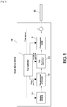
- Fig. 1 is a block diagram showing the configuration of the image pickup device 10 of the image processing system 1 of this embodiment.
- the image pickup device 10 includes an image sensor 11, a development processor 12, a first gradation converter 13, a compression coder 14, and a first controller 15.
- the image sensor 11 is an image sensor such as for example a CMOS (Complementary MOS) image sensor or a CCD (Charge Coupled Device) image sensor.
- the image sensor 11 converts light into RGB electric signals depending on its intensity, converts the analog signals into a digital signal series, and outputs the signal series as RAW data.
- the development processor 12 converts the RAW data output from the image sensor 11 into image data having a first gamut.
- the development processor 12 is for example a circuit or the like configured to convert RAW data into image data having the first gamut by using a conversion matrix (first conversion matrix) or the like.
- the first gamut will be described later.
- the first gradation converter 13 adjusts the image data having the first gamut obtained by the development processor 12 by using imaging gamma (e.g., S-Log gamma, etc.) under the assumption that the image tone is to be adjusted after taking an image.
- imaging gamma e.g., S-Log gamma, etc.
- This kind of imaging gamma is designed as a non-linear function so as to involve shadow and highlight information as much as possible. The more the shadow and highlight information, the greater the flexibility of color correction in post-production.
- the compression coder 14 compression-codes the image data having the first gamut output from the first gradation converter 13. For example, MPEG (Moving Picture Experts Group) is adopted as a compression-coding method.
- MPEG Motion Picture Experts Group
- the compression-coded image data having the first gamut is transmitted to the decoder unit 30 via the transmission path 20.
- the first controller 15 controls the operations of the image sensor 11, the development processor 12, the first gradation converter 13, the compression coder 14, and the like.
- the first controller 15 is capable of selecting the first gamut or the first conversion matrix for the development processor 12, selecting the imaging gamma for the first gradation converter 13, and the like.
- the first controller 15 transmits metadata to the decoder unit 30 via the transmission path 20.
- the metadata includes information on the first gamut selected for the development processor 12, information on the imaging gamma selected for the first gradation converter 13, and the like.
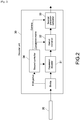
- the decoder unit 30 is an image processing device configured to create image data having the desired gamut and the desired gamma from image data transmitted from the image pickup device 10.
- Fig. 2 is a block diagram showing the configuration of the decoder unit 30 of the image processing system 1 of this embodiment.
- the decoder unit 30 includes an expansion decoder 31, a gamut converter 32, a second gradation converter 33, and a second controller 34.
- the expansion decoder 31 expansion-decodes the compression-coded image data having the first gamut transmitted from the image pickup device 10 via the transmission path 20.
- the gamut converter 32 converts the image data expansion-decoded by the expansion decoder 31 into image data having a second gamut depending on a purpose of the image data.
- the gamut converter 32 is for example a circuit configured to convert the gamut of image data by using a conversion matrix (second conversion matrix) or the like. The second gamut will be described later.
- the second gradation converter 33 gamma-adjusts the image data having the second gamut output from the gamut converter 32 as necessary to thereby adjust gradation.
- the second controller 34 controls the expansion decoder 31, the second gradation converter 33, and the gamut converter 32.
- the second controller 34 sets one kind of gamut selected from a plurality of kinds of gamut, which the decoder unit 30 is capable of setting, as the second gamut based on an instruction from for example a user or the like.
- the plurality of kinds of gamut, which the decoder unit 30 is capable of setting are specifically for example S-Gamut 3, ITU-709, ITU 2020, DCI P3, film gamut, and the like.
- the second gamut may be selected before the image processing system 1 processes an image, or may be arbitrarily selected by a user when the image processing system 1 processes an image.
- the second controller 34 obtains information on the first gamut from metadata transmitted from the image pickup device 10 via the transmission path 20, and sets a conversion matrix corresponding to the combination of the first gamut and the second gamut for the gamut converter 32.
- the second controller 34 is capable of selecting the gamma, which is applied to image data by the second gradation converter 33, based on an instruction from a user for example.
- ITU-709 As gamut for liquid crystal television sets, there are known ITU-709, ITU2020, and the like.
- ITU-709 is a gamut mode in conformity to ITU-R BT.709 standard.
- ITU2020 corresponds to liquid crystal television sets supporting 4K.
- S-Gamut3 is gamut for a wide gamut mode supported by a digital cinematography camera manufactured by Sony Corporation.
- DCI P3 Digital Cinema Initiatives
- DCI Digital Cinema Initiatives
- the decoder unit 30 sets, as the second gamut, one kind of gamut selected by a user out of the plurality of above-mentioned kinds of gamut. Meanwhile, as the first gamut applied for the development processor 12 of the image pickup device 10, gamut containing the plurality of kinds of gamut, which the decoder unit 30 is capable of setting, is used.
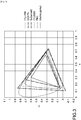
- Fig. 3 is a diagram showing the respective kinds of gamut, i.e., ITU-709, ITU2020, DCI P3, S-Gamut3, film gamut, the visible gamut, which are compared with one another.
- gamut i.e., ITU-709, ITU2020, DCI P3, S-Gamut3, film gamut, the visible gamut, which are compared with one another.
- S-Gamut3 includes all the above-mentioned kinds of gamut except the visible gamut, i.e., ITU-709, ITU2020, DCI P3, and film gamut. Under the relation of the plurality of kinds of gamut, S-Gamut3 may be used as the first gamut. That is, if one kind of gamut out of the plurality of kinds of gamut, which the decoder unit 30 is capable of setting, includes the other kinds of gamut, the one kind of gamut may be used as the first gamut for the image pickup device 10.
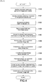
- Fig. 4 is a flowchart showing the operations of the image processing system 1.
- the first controller 15 sets a first conversion matrix for the development processor 12.
- the first conversion matrix is used to convert RAW data into image data having a first gamut. Further, the first controller 15 sets an imaging gamma for the first gradation converter 13 (Step S101).
- the first controller 15 creates metadata at least containing information on the first gamut, and transmits the metadata to the decoder unit 30 via the transmission path 20 (Step S102).
- the second controller 34 of the decoder unit 30 receives the metadata via the transmission path 20. Then, the second controller 34 sets the first gamut and a second conversion matrix for the gamut converter 32.
- the first gamut is specified by information on the first gamut contained in the metadata.
- the second conversion matrix corresponds to the combination of the first gamut and a second gamut selected by the decoder unit 30 (Step S103).
- a memory of the second controller 34 prestores information on second conversion matrixes corresponding to various gamut combinations, respectively.
- the second controller 34 refers to the memory and is capable of obtaining information on the second conversion matrix.
- the second conversion matrix corresponds to the combination of the first gamut and the second gamut.
- the first gamut is contained in the metadata, and the image pickup device 10 notifies the second controller 34 of the metadata.
- the image sensor 11 supplies RAW data to the development processor 12 (Step S104). Then the development processor 12 converts the RAW data into image data having a first gamut by using the above-mentioned first conversion matrix (Step S105).
- the first controller 15 may obtain information on all the kinds of gamut from the decoder unit 30 via the transmission path 20 and may automatically specify a first gamut based on the information, whereby the image pickup device 10 sets a conversion matrix.
- the first gradation converter 13 gamma-adjusts the image data having the first gamut output from the development processor 12 by using the selected imaging gamma (Step S106).
- the compression coder 14 compression-codes the image data having the first gamut supplied from the first gradation converter 13 (Step S107).
- the compressed image data obtained by the compression coder 14 is transmitted to the decoder unit 30 via the transmission path 20 (Step S108).
- a lossy compression method such as MPEG is used as a compression coding method for images.
- the present technology is not limited thereto.
- a lossless compression method may be adopted.
- a transmission system such as for example an SDI (Serial Digital Interface) is used for the transmission path 20 between the image pickup device 10 and the decoder unit 30.
- SDI Serial Digital Interface
- the transmission system of the present technology is not limited to SDI.
- the expansion decoder 31 expansion-decodes the image data transmitted to the decoder unit 30 (Step S109).
- the gamut converter 32 converts the image data having the first gamut expansion-decoded by the expansion decoder 31 into image data having a second gamut by using the second conversion matrix (Step S110). As a result, image data having a gamut for purpose is obtained.
- the second gradation converter 33 adjusts the image data having the second gamut output from the gamut converter 32 by using a gamma set depending on a purpose of the image data.
- the image data may not be gamma-adjusted, but may be output as it is (Step Sill).
- S-Gamut3 is set as the first gamut
- one of a plurality of kinds of gamut, which are contained in the gamut of S-Gamut3 is selected as the second gamut.
- kinds of gamut include ITU-709, ITU2020, DCI P3, and film gamut.
- the decoder unit 30 may employ the gamut of S-Gamut3 as the second gamut. In this case, the gamut converter 32 does not convert the gamut.
- the image pickup device 10 develops RAW data as image data having a gamut containing all the kinds of gamut, which the decoder unit 30 is capable of setting. Because of this, irrespective of a plurality of kinds of gamut, which the decoder unit 30 is capable of setting, of converted image data, the color reproducibility of the image is not decreased.
- the gamut same as the first gamut is set as the second gamut (e.g., S-Gamut3, etc.), it is not necessary for the decoder unit 30 to convert the gamut, which may lead to speed enhancement.
- the volume of transmitted data is smaller than that of a method of transmitting RAW data to the decoder unit 30 as it is, which may lead to speed enhancement.
- the decoder unit 30 under the relation of all the kinds of gamut, which the decoder unit 30 is capable of setting, if one kind of gamut includes the other kinds of gamut, the one kind of gamut may be used as the first gamut.
- the present technology is not limited to this.
- a new gamut 51 may be set as the first gamut.
- the new gamut 51 contains all the kinds of gamut, which the decoder unit 30 is capable of setting, and is wider than S-Gamut3. As a result, also, the color reproducibility of an image is not decreased, and the volume of transmitted data is smaller, which may lead to speed enhancement.
- the decoder unit 30 is capable of setting the following kinds of gamut, i.e., ITU-709, ITU2020, DCI P3, S-Gamut3, and film gamut.
- gamut i.e., ITU-709, ITU2020, DCI P3, S-Gamut3, and film gamut.
- the present technology is not limited to them.
- the decoder unit 30 is capable of setting three kinds of gamut, i.e., ITU-709, ITU2020, and DCI P3.
- ITU2020 contains the other kinds of gamut, i.e., ITU-709 and DCI P3. That is, ITU2020 may be the first gamut.
Description
- The present technology relates to an image processing system including an image pickup device having a development function and an image processing device configured to convert image data obtained by the image pickup device into image data having a gamut for purpose. The present technology further relates to an image processing method.
- An image pickup device develops RAW data obtained by an image sensor into image data having a desired gamut, and outputs the data. The ideal gamut for image data is different depending on purposes of image data such as for example a television set, a projector, a video film, and printing. Because of this, if image data output from an image pickup device having a development function as described above is used for a purpose different from the purpose planned for the image pickup device, it is necessary to convert the gamut of the image data supplied from the image pickup device into a gamut for the different purpose.
- However, in this case, it is not possible to reproduce the gamut part, which is already lacked from RAW data, of the image data output from the image pickup device. Because of this, if the image data output from the image pickup device is converted into image data having gamut wider than the gamut of the image data output from the image pickup device, color reproducibility of is decreased.
- In view of this, there is known a method of transmitting RAW data obtained by an image sensor of an image pickup device to an image processing device via a medium or via communication, and developing the RAW data into image data having a desired gamut by an image processing device (e.g., see PTL 1). According to this method, the gamut and the gamma for image data may be selected at will when developing the image data. However, because RAW data is transmitted as it is via a medium or via communication, the volume of transmitted data is large, and speed enhancement is hindered.
- [PTL 1]
Japanese Patent Application Laid-open No.2009-033385 US 2007/2797031 (Fukuda Michitaka [JP],EP 1197971 A2 (Seiko Epson Corp [JP])
Prior Art Also Includes:EP1370070 , Sony Corporation "XAVC Specification Overview rev 2", 13 September 2013 - An image processing system, which includes an image pickup device capable of developing image data and an image processing device capable of converting the gamut of the image data output from the image pickup device into gamut for purpose, still has various unsolved problems concerning performances such as color reproducibility and speed. It is desirable to take measures against such problems.
- In view of the above-mentioned circumstances, it is desirable to to provide an image processing system and an image processing method having excellent performances such as excellent color reproducibility and fast transmission.
- Aspects of the present disclosure are defined by the appended claims.
- As described above, according to the present technology, there is realized an image processing system having excellent performances such as excellent color reproducibility and fast transmission.
-
- [
Fig. 1] Fig. 1 is a block diagram showing the configuration of animage pickup device 10 of animage processing system 1 of this embodiment. - [
Fig. 2] Fig. 2 is a block diagram showing the configuration of adecoder unit 30 of theimage processing system 1 of this embodiment. - [
Fig. 3] Fig. 3 is a diagram showing various kinds of gamut, which are compared with one another. - [
Fig. 4] Fig. 4 is a flowchart showing the operations of theimage processing system 1 of this embodiment. - [
Fig. 5 ]Fig. 3 is a diagram illustrating various kinds of gamut of a modification example. - Hereinafter, an embodiment of the present technology will be described with reference to the drawings.
-
Fig. 1 andFig. 2 are block diagrams each showing the configuration of an image processing system according to a first embodiment of the present technology. - The
image processing system 1 includes animage pickup device 10, atransmission path 20, and a decoder unit (image processing device) 30. -
Fig. 1 is a block diagram showing the configuration of theimage pickup device 10 of theimage processing system 1 of this embodiment. - The
image pickup device 10 includes animage sensor 11, adevelopment processor 12, afirst gradation converter 13, acompression coder 14, and afirst controller 15. - The
image sensor 11 is an image sensor such as for example a CMOS (Complementary MOS) image sensor or a CCD (Charge Coupled Device) image sensor. Theimage sensor 11 converts light into RGB electric signals depending on its intensity, converts the analog signals into a digital signal series, and outputs the signal series as RAW data. - The
development processor 12 converts the RAW data output from theimage sensor 11 into image data having a first gamut. Specifically thedevelopment processor 12 is for example a circuit or the like configured to convert RAW data into image data having the first gamut by using a conversion matrix (first conversion matrix) or the like. The first gamut will be described later. - The
first gradation converter 13 adjusts the image data having the first gamut obtained by thedevelopment processor 12 by using imaging gamma (e.g., S-Log gamma, etc.) under the assumption that the image tone is to be adjusted after taking an image. This kind of imaging gamma is designed as a non-linear function so as to involve shadow and highlight information as much as possible. The more the shadow and highlight information, the greater the flexibility of color correction in post-production. - The
compression coder 14 compression-codes the image data having the first gamut output from thefirst gradation converter 13. For example, MPEG (Moving Picture Experts Group) is adopted as a compression-coding method. The compression-coded image data having the first gamut is transmitted to thedecoder unit 30 via thetransmission path 20. - The
first controller 15 controls the operations of theimage sensor 11, thedevelopment processor 12, thefirst gradation converter 13, thecompression coder 14, and the like. For example, thefirst controller 15 is capable of selecting the first gamut or the first conversion matrix for thedevelopment processor 12, selecting the imaging gamma for thefirst gradation converter 13, and the like. Further, thefirst controller 15 transmits metadata to thedecoder unit 30 via thetransmission path 20. The metadata includes information on the first gamut selected for thedevelopment processor 12, information on the imaging gamma selected for thefirst gradation converter 13, and the like. - The
decoder unit 30 is an image processing device configured to create image data having the desired gamut and the desired gamma from image data transmitted from theimage pickup device 10. -
Fig. 2 is a block diagram showing the configuration of thedecoder unit 30 of theimage processing system 1 of this embodiment. - The
decoder unit 30 includes anexpansion decoder 31, agamut converter 32, asecond gradation converter 33, and asecond controller 34. - The
expansion decoder 31 expansion-decodes the compression-coded image data having the first gamut transmitted from theimage pickup device 10 via thetransmission path 20. - The
gamut converter 32 converts the image data expansion-decoded by theexpansion decoder 31 into image data having a second gamut depending on a purpose of the image data. Specifically thegamut converter 32 is for example a circuit configured to convert the gamut of image data by using a conversion matrix (second conversion matrix) or the like. The second gamut will be described later. - The
second gradation converter 33 gamma-adjusts the image data having the second gamut output from thegamut converter 32 as necessary to thereby adjust gradation. - The
second controller 34 controls theexpansion decoder 31, thesecond gradation converter 33, and thegamut converter 32. - The
second controller 34 sets one kind of gamut selected from a plurality of kinds of gamut, which thedecoder unit 30 is capable of setting, as the second gamut based on an instruction from for example a user or the like. Here, the plurality of kinds of gamut, which thedecoder unit 30 is capable of setting, are specifically for example S-Gamut 3, ITU-709, ITU 2020, DCI P3, film gamut, and the like. The second gamut may be selected before theimage processing system 1 processes an image, or may be arbitrarily selected by a user when theimage processing system 1 processes an image. - The
second controller 34 obtains information on the first gamut from metadata transmitted from theimage pickup device 10 via thetransmission path 20, and sets a conversion matrix corresponding to the combination of the first gamut and the second gamut for thegamut converter 32. - Further, the
second controller 34 is capable of selecting the gamma, which is applied to image data by thesecond gradation converter 33, based on an instruction from a user for example. - Here, the first gamut and the second gamut will be described.
- There are various kinds of gamut for image data for different purposes.
- For example, as gamut for liquid crystal television sets, there are known ITU-709, ITU2020, and the like. ITU-709 is a gamut mode in conformity to ITU-R BT.709 standard. ITU2020 corresponds to liquid crystal television sets supporting 4K.
- As gamut for digital cinema, there are known S-Gamut3, DCI P3, and ACES. S-Gamut3 is gamut for a wide gamut mode supported by a digital cinematography camera manufactured by Sony Corporation.
- DCI P3 (Digital Cinema Initiatives) is one kind of gamut proposed by DCI (Digital Cinema Initiatives) as gamut for images projected by projectors in movie theaters.
- The
decoder unit 30 sets, as the second gamut, one kind of gamut selected by a user out of the plurality of above-mentioned kinds of gamut. Meanwhile, as the first gamut applied for thedevelopment processor 12 of theimage pickup device 10, gamut containing the plurality of kinds of gamut, which thedecoder unit 30 is capable of setting, is used. -
Fig. 3 is a diagram showing the respective kinds of gamut, i.e., ITU-709, ITU2020, DCI P3, S-Gamut3, film gamut, the visible gamut, which are compared with one another. - It is understood that S-Gamut3 includes all the above-mentioned kinds of gamut except the visible gamut, i.e., ITU-709, ITU2020, DCI P3, and film gamut. Under the relation of the plurality of kinds of gamut, S-Gamut3 may be used as the first gamut. That is, if one kind of gamut out of the plurality of kinds of gamut, which the
decoder unit 30 is capable of setting, includes the other kinds of gamut, the one kind of gamut may be used as the first gamut for theimage pickup device 10. - Next, the operations of the
image processing system 1 of this embodiment will be described. -
Fig. 4 is a flowchart showing the operations of theimage processing system 1. - First, as the operation of the
image pickup device 10, thefirst controller 15 sets a first conversion matrix for thedevelopment processor 12. The first conversion matrix is used to convert RAW data into image data having a first gamut. Further, thefirst controller 15 sets an imaging gamma for the first gradation converter 13 (Step S101). - Next, the
first controller 15 creates metadata at least containing information on the first gamut, and transmits the metadata to thedecoder unit 30 via the transmission path 20 (Step S102). - The
second controller 34 of thedecoder unit 30 receives the metadata via thetransmission path 20. Then, thesecond controller 34 sets the first gamut and a second conversion matrix for thegamut converter 32. The first gamut is specified by information on the first gamut contained in the metadata. The second conversion matrix corresponds to the combination of the first gamut and a second gamut selected by the decoder unit 30 (Step S103). - Here, a memory of the
second controller 34 prestores information on second conversion matrixes corresponding to various gamut combinations, respectively. Thesecond controller 34 refers to the memory and is capable of obtaining information on the second conversion matrix. The second conversion matrix corresponds to the combination of the first gamut and the second gamut. The first gamut is contained in the metadata, and theimage pickup device 10 notifies thesecond controller 34 of the metadata. - The
image sensor 11 supplies RAW data to the development processor 12 (Step S104). Then thedevelopment processor 12 converts the RAW data into image data having a first gamut by using the above-mentioned first conversion matrix (Step S105). - Note that the
first controller 15 may obtain information on all the kinds of gamut from thedecoder unit 30 via thetransmission path 20 and may automatically specify a first gamut based on the information, whereby theimage pickup device 10 sets a conversion matrix. - Next, the
first gradation converter 13 gamma-adjusts the image data having the first gamut output from thedevelopment processor 12 by using the selected imaging gamma (Step S106). - Next, the
compression coder 14 compression-codes the image data having the first gamut supplied from the first gradation converter 13 (Step S107). The compressed image data obtained by thecompression coder 14 is transmitted to thedecoder unit 30 via the transmission path 20 (Step S108). - Note that a lossy compression method such as MPEG is used as a compression coding method for images. However, the present technology is not limited thereto. A lossless compression method may be adopted.
- A transmission system such as for example an SDI (Serial Digital Interface) is used for the
transmission path 20 between theimage pickup device 10 and thedecoder unit 30. As a matter of course, the transmission system of the present technology is not limited to SDI. - The
expansion decoder 31 expansion-decodes the image data transmitted to the decoder unit 30 (Step S109). - Next, the
gamut converter 32 converts the image data having the first gamut expansion-decoded by theexpansion decoder 31 into image data having a second gamut by using the second conversion matrix (Step S110). As a result, image data having a gamut for purpose is obtained. - Next, the
second gradation converter 33 adjusts the image data having the second gamut output from thegamut converter 32 by using a gamma set depending on a purpose of the image data. Alternatively, the image data may not be gamma-adjusted, but may be output as it is (Step Sill). - Here, if S-Gamut3 is set as the first gamut, one of a plurality of kinds of gamut, which are contained in the gamut of S-Gamut3, is selected as the second gamut. Examples of such kinds of gamut include ITU-709, ITU2020, DCI P3, and film gamut.
- It is assumed that the
decoder unit 30 may employ the gamut of S-Gamut3 as the second gamut. In this case, thegamut converter 32 does not convert the gamut. - As described above, according to the
image processing system 1 of this embodiment, theimage pickup device 10 develops RAW data as image data having a gamut containing all the kinds of gamut, which thedecoder unit 30 is capable of setting. Because of this, irrespective of a plurality of kinds of gamut, which thedecoder unit 30 is capable of setting, of converted image data, the color reproducibility of the image is not decreased. - If the gamut same as the first gamut is set as the second gamut (e.g., S-Gamut3, etc.), it is not necessary for the
decoder unit 30 to convert the gamut, which may lead to speed enhancement. - Further, the volume of transmitted data is smaller than that of a method of transmitting RAW data to the
decoder unit 30 as it is, which may lead to speed enhancement. - In the above-mentioned embodiment, under the relation of all the kinds of gamut, which the
decoder unit 30 is capable of setting, if one kind of gamut includes the other kinds of gamut, the one kind of gamut may be used as the first gamut. The present technology is not limited to this. - For example, as shown in
Fig. 5 , anew gamut 51 may be set as the first gamut. Thenew gamut 51 contains all the kinds of gamut, which thedecoder unit 30 is capable of setting, and is wider than S-Gamut3. As a result, also, the color reproducibility of an image is not decreased, and the volume of transmitted data is smaller, which may lead to speed enhancement. - The
decoder unit 30 is capable of setting the following kinds of gamut, i.e., ITU-709, ITU2020, DCI P3, S-Gamut3, and film gamut. The present technology is not limited to them. - For example, let's assume that the
decoder unit 30 is capable of setting three kinds of gamut, i.e., ITU-709, ITU2020, and DCI P3. In this case, ITU2020 contains the other kinds of gamut, i.e., ITU-709 and DCI P3. That is, ITU2020 may be the first gamut. - The present application contains subject matter related to that disclosed in Japanese Priority Patent Application
JP 2013-257372 - It should be understood by those skilled in the art that various modifications, combinations, subcombinations and alterations may occur depending on design requirements and other factors insofar as they are within the scope of the appended claims.
-
- 1
- Image processing system
- 10
- Image pickup device
- 11
- Image sensor
- 12
- Development processor
- 13
- First gradation converter
- 14
- Compression coder
- 15
- First controller
- 20
- Transmission path
- 30
- Decoder unit
- 31
- Expansion decoder
- 32
- Gamut converter
- 33
- Second gradation converter
- 34
- Second controller
Claims (9)
- An imaging processing system (1) comprising:an image pickup device (10) including circuitry (12) configured to
create image data having a first gamut, the first gamut encompassing all the kinds of gamut which a decoder unit is capable of setting, from raw image data, the first gamut being automatically selected based on information on all the kinds of gamut which the decoder unit is capable of setting received from the decoder unit via a predetermined transmission path; and
wherein when one kind of gamut which the decoder unit is capable of setting includes the other kinds of gamut which the decoder is capable of setting, the one kind of gamut is used as the first gamut;
compression-code (14) the image data including the first gamut to generate compression-coded image data; andan image processing device (30) including circuitry (31) configured to
decode the compression-coded image data to generate uncompressed image data including the first gamut, andconvert (32) the uncompressed image data including the first gamut into image data including a second gamut, the second gamut being selected from a plurality of gamuts, the plurality of gamuts being all the kinds of gamut which the decoder unit is capable of setting,wherein the image pickup device transmits the compression-coded image data to the image processing device via the predetermined transmission path;wherein the image pickup device further transmits metadata including information regarding the first gamut to the image processing device via the predetermined transmission path;
wherein the circuitry of the image processing device is further configured to convert the uncompressed image data including the first gamut into the image data including the second gamut using a conversion matrix and wherein the conversion matrix corresponds to a predetermined combination of the first gamut and the second gamut;wherein the circuitry of the image processing device is further configured to store a plurality of matrices, each corresponding to a different combination of the first gamut with the second gamut; and wherein the circuitry of the image processing device is further configured to select one of the plurality of matrices as the conversion matrix based on gamut metadata received from the image pickup device. - The system according to claim 1, wherein the metadata further includes information regarding imaging gamma.
- The system according to claim 1, wherein the first gamut includes S-Gamut3.
- The system according to claim 3, wherein the second gamut includes DCI P3, ACES, ITU-709, ITU-R BT. 709, ITU 2020, or a film gamut.
- The system according to claim 1, wherein the circuitry of the image pickup device is further configured to adjust a gamma of the image data including the first gamut.
- The system according to claim 1, wherein the circuitry of the image pickup device is further configured to use lossy compression when compression-coding the image data including the first gamut.
- The system according to claim 1, wherein the circuitry of the image processing device is further configured to adjust a gradation of the image data including the second gamut using predetermined gamma information.
- An image processing method, comprising:creating, with circuitry of a first device, image data having a first gamut, the first gamut encompassing all the kinds of gamut which a decoder unit is capable of setting, from raw image data, the first gamut being automatically selected based on information on all the kinds of gamut which the decoder unit is capable of setting received from the decoder unit via a predetermined transmission path, wherein when one kind of gamut which the decoder unit is capable of setting includes the other kinds of gamut which the decoder is capable of setting, the one kind of gamut is used as the first gamut;compression-coding, with the circuitry of the first device, the image data including the first gamut to generate compression-coded image data;decoding, with circuitry of a second device, the compression-coded image data to generate uncompressed image data including the first gamut; andconverting, with the circuitry of the second device, the uncompressed image data including the first gamut into image data including a second gamut, the second gamut being selected from a plurality of gamuts, the plurality of gamuts being all the kinds of gamut which the decoder unit is capable of setting,wherein the first device transmits the compression-coded image data to the second device via the predetermined transmission path;wherein the first device further transmits metadata including information regarding the first gamut to the second device via the predetermined transmission path; converting, with the circuitry of the second device, the uncompressed image data including the first gamut into the image data including the second gamut using a conversion matrix and wherein the conversion matrix corresponds to a predetermined combination of the first gamut and the second gamut;storing, with the circuitry of the second device, a plurality of matrices, each corresponding to a different combination of the first gamut with the second gamut; and
selecting, with the circuitry of the second device, one of the plurality of matrices as the conversion matrix based on gamut metadata received from the first device. - A non-transitory computer-readable medium encoded with computer-readable instructions thereon, the computer readable instructions, when executed by a computer, cause the computer to perform the method according to Claim 8.
Applications Claiming Priority (2)
| Application Number | Priority Date | Filing Date | Title |
|---|---|---|---|
| JP2013257372A JP6135490B2 (en) | 2013-12-12 | 2013-12-12 | Movie image processing system and movie image processing method |
| PCT/JP2014/005776 WO2015087489A1 (en) | 2013-12-12 | 2014-11-18 | Image processing system and image processing method |
Publications (2)
| Publication Number | Publication Date |
|---|---|
| EP3080977A1 EP3080977A1 (en) | 2016-10-19 |
| EP3080977B1 true EP3080977B1 (en) | 2020-04-29 |
Family
ID=52016121
Family Applications (1)
| Application Number | Title | Priority Date | Filing Date |
|---|---|---|---|
| EP14809535.9A Active EP3080977B1 (en) | 2013-12-12 | 2014-11-18 | Image processing system and image processing method |
Country Status (4)
| Country | Link |
|---|---|
| US (2) | US10440234B2 (en) |
| EP (1) | EP3080977B1 (en) |
| JP (1) | JP6135490B2 (en) |
| WO (1) | WO2015087489A1 (en) |
Families Citing this family (2)
| Publication number | Priority date | Publication date | Assignee | Title |
|---|---|---|---|---|
| JP7057159B2 (en) * | 2018-03-02 | 2022-04-19 | キヤノン株式会社 | Image processing equipment, image processing methods and programs |
| JP2022097133A (en) * | 2020-12-18 | 2022-06-30 | 富士フイルムビジネスイノベーション株式会社 | Image processing device and image processing program |
Citations (1)
| Publication number | Priority date | Publication date | Assignee | Title |
|---|---|---|---|---|
| EP1370070A1 (en) * | 2002-06-06 | 2003-12-10 | GRETAG IMAGING Trading AG | Color management via reference gamut |
Family Cites Families (14)
| Publication number | Priority date | Publication date | Assignee | Title |
|---|---|---|---|---|
| EP1197917A3 (en) | 2000-10-13 | 2005-03-23 | Seiko Epson Corporation | Apparatus, method and computer program product for providing output image adjustment for image files |
| US7289663B2 (en) * | 2002-07-24 | 2007-10-30 | Eastman Kodak Company | Producing an extended color gamut luminance-chrominance digital image from a captured image |
| US7609425B2 (en) * | 2003-01-31 | 2009-10-27 | Canon Kabushiki Kaisha | Image data processing apparatus, method, storage medium and program |
| JP2004282599A (en) * | 2003-03-18 | 2004-10-07 | Matsushita Electric Ind Co Ltd | Image display device, image display method, program, and recording medium |
| JP4863438B2 (en) * | 2004-09-10 | 2012-01-25 | キヤノン株式会社 | Data processing apparatus and processing method |
| JP2007215074A (en) * | 2006-02-13 | 2007-08-23 | Seiko Epson Corp | Image data analysis apparatus, image data generating apparatus, image data analysis method, and image data generating method |
| JP2008017441A (en) * | 2006-06-06 | 2008-01-24 | Ricoh Co Ltd | Data processing apparatus, data processing method, and program |
| JP2008245248A (en) * | 2007-02-28 | 2008-10-09 | Fujifilm Corp | Image capturing apparatus |
| JP4985180B2 (en) | 2007-07-26 | 2012-07-25 | ソニー株式会社 | Image processing apparatus, image processing method, image processing program, and imaging apparatus |
| JP5014099B2 (en) * | 2007-12-11 | 2012-08-29 | キヤノン株式会社 | Imaging apparatus and control method thereof |
| JP2010011191A (en) * | 2008-06-27 | 2010-01-14 | Sony Corp | Recording device and recording control method, reproduction device and reproduction control method, output device and output control method, and program |
| JP5474586B2 (en) * | 2010-01-25 | 2014-04-16 | オリンパス株式会社 | Image processing device |
| JP5904281B2 (en) * | 2012-08-10 | 2016-04-13 | 株式会社ニコン | Image processing method, image processing apparatus, imaging apparatus, and image processing program |
| WO2014193531A1 (en) * | 2013-05-31 | 2014-12-04 | Intel Corporation | Semi-fixed-hue gamut compression |
-
2013
- 2013-12-12 JP JP2013257372A patent/JP6135490B2/en active Active
-
2014
- 2014-11-18 US US15/101,635 patent/US10440234B2/en active Active
- 2014-11-18 WO PCT/JP2014/005776 patent/WO2015087489A1/en active Application Filing
- 2014-11-18 EP EP14809535.9A patent/EP3080977B1/en active Active
-
2019
- 2019-09-11 US US16/567,680 patent/US11606479B2/en active Active
Patent Citations (1)
| Publication number | Priority date | Publication date | Assignee | Title |
|---|---|---|---|---|
| EP1370070A1 (en) * | 2002-06-06 | 2003-12-10 | GRETAG IMAGING Trading AG | Color management via reference gamut |
Non-Patent Citations (1)
| Title |
|---|
| SONY CORPORATION: "XAVC Specification Overview rev 2", 13 September 2013 (2013-09-13), XP055568003, Retrieved from the Internet <URL:https://web.archive.org/web/20130920104732/http://www.xavc-info.org/xavc/share/data/XAVC_SpecificationOverview_Rev2_130913.pdf> [retrieved on 20190312], DOI: 10.1016/S0140-6736(14)61682-2 * |
Also Published As
| Publication number | Publication date |
|---|---|
| WO2015087489A1 (en) | 2015-06-18 |
| JP2015115833A (en) | 2015-06-22 |
| US20200007719A1 (en) | 2020-01-02 |
| US10440234B2 (en) | 2019-10-08 |
| JP6135490B2 (en) | 2017-05-31 |
| US20170324886A1 (en) | 2017-11-09 |
| EP3080977A1 (en) | 2016-10-19 |
| US11606479B2 (en) | 2023-03-14 |
Similar Documents
| Publication | Publication Date | Title |
|---|---|---|
| JP7407373B2 (en) | Display device, display method, and computer program | |
| JP6558599B2 (en) | Playback apparatus, playback method, and computer program | |
| US10728567B2 (en) | Decoding device and decoding method, encoding device, and encoding method | |
| JP6202330B2 (en) | Decoding device and decoding method, and encoding device and encoding method | |
| RU2710888C2 (en) | Method and device for colour picture encoding and decoding | |
| CN109479111B (en) | Image processing apparatus, reproduction apparatus, image processing method, and reproduction method | |
| US11606479B2 (en) | Image processing system and image processing method | |
| US10009588B2 (en) | Image processing apparatus and imaging apparatus | |
| JP2006033575A (en) | Signal processing device and method, and program | |
| EP2966869B1 (en) | Decoding device, decoding method, encoding device, and recording medium | |
| JP6653353B2 (en) | Transmission / reception system, transmission device, reception device, and image transmission method | |
| US9894315B2 (en) | Image capturing apparatus, image processing apparatus and method, image processing system, and control method for image capturing apparatus | |
| US10205967B2 (en) | Extended YCC format for backward-compatible P3 camera video | |
| BR112021009839A2 (en) | decoding an image | |
| JP2008072594A (en) | Signal processor, signal processing method, and program |
Legal Events
| Date | Code | Title | Description |
|---|---|---|---|
| PUAI | Public reference made under article 153(3) epc to a published international application that has entered the european phase |
Free format text: ORIGINAL CODE: 0009012 |
|
| 17P | Request for examination filed |
Effective date: 20160611 |
|
| AK | Designated contracting states |
Kind code of ref document: A1 Designated state(s): AL AT BE BG CH CY CZ DE DK EE ES FI FR GB GR HR HU IE IS IT LI LT LU LV MC MK MT NL NO PL PT RO RS SE SI SK SM TR |
|
| AX | Request for extension of the european patent |
Extension state: BA ME |
|
| DAX | Request for extension of the european patent (deleted) | ||
| STAA | Information on the status of an ep patent application or granted ep patent |
Free format text: STATUS: EXAMINATION IS IN PROGRESS |
|
| 17Q | First examination report despatched |
Effective date: 20171002 |
|
| GRAP | Despatch of communication of intention to grant a patent |
Free format text: ORIGINAL CODE: EPIDOSNIGR1 |
|
| STAA | Information on the status of an ep patent application or granted ep patent |
Free format text: STATUS: GRANT OF PATENT IS INTENDED |
|
| INTG | Intention to grant announced |
Effective date: 20191206 |
|
| GRAS | Grant fee paid |
Free format text: ORIGINAL CODE: EPIDOSNIGR3 |
|
| GRAA | (expected) grant |
Free format text: ORIGINAL CODE: 0009210 |
|
| STAA | Information on the status of an ep patent application or granted ep patent |
Free format text: STATUS: THE PATENT HAS BEEN GRANTED |
|
| AK | Designated contracting states |
Kind code of ref document: B1 Designated state(s): AL AT BE BG CH CY CZ DE DK EE ES FI FR GB GR HR HU IE IS IT LI LT LU LV MC MK MT NL NO PL PT RO RS SE SI SK SM TR |
|
| REG | Reference to a national code |
Ref country code: GB Ref legal event code: FG4D |
|
| REG | Reference to a national code |
Ref country code: CH Ref legal event code: EP |
|
| REG | Reference to a national code |
Ref country code: DE Ref legal event code: R096 Ref document number: 602014064615 Country of ref document: DE |
|
| REG | Reference to a national code |
Ref country code: AT Ref legal event code: REF Ref document number: 1265059 Country of ref document: AT Kind code of ref document: T Effective date: 20200515 |
|
| REG | Reference to a national code |
Ref country code: IE Ref legal event code: FG4D |
|
| REG | Reference to a national code |
Ref country code: NL Ref legal event code: MP Effective date: 20200429 |
|
| REG | Reference to a national code |
Ref country code: LT Ref legal event code: MG4D |
|
| PG25 | Lapsed in a contracting state [announced via postgrant information from national office to epo] |
Ref country code: LT Free format text: LAPSE BECAUSE OF FAILURE TO SUBMIT A TRANSLATION OF THE DESCRIPTION OR TO PAY THE FEE WITHIN THE PRESCRIBED TIME-LIMIT Effective date: 20200429 Ref country code: GR Free format text: LAPSE BECAUSE OF FAILURE TO SUBMIT A TRANSLATION OF THE DESCRIPTION OR TO PAY THE FEE WITHIN THE PRESCRIBED TIME-LIMIT Effective date: 20200730 Ref country code: FI Free format text: LAPSE BECAUSE OF FAILURE TO SUBMIT A TRANSLATION OF THE DESCRIPTION OR TO PAY THE FEE WITHIN THE PRESCRIBED TIME-LIMIT Effective date: 20200429 Ref country code: IS Free format text: LAPSE BECAUSE OF FAILURE TO SUBMIT A TRANSLATION OF THE DESCRIPTION OR TO PAY THE FEE WITHIN THE PRESCRIBED TIME-LIMIT Effective date: 20200829 Ref country code: SE Free format text: LAPSE BECAUSE OF FAILURE TO SUBMIT A TRANSLATION OF THE DESCRIPTION OR TO PAY THE FEE WITHIN THE PRESCRIBED TIME-LIMIT Effective date: 20200429 Ref country code: NO Free format text: LAPSE BECAUSE OF FAILURE TO SUBMIT A TRANSLATION OF THE DESCRIPTION OR TO PAY THE FEE WITHIN THE PRESCRIBED TIME-LIMIT Effective date: 20200729 Ref country code: PT Free format text: LAPSE BECAUSE OF FAILURE TO SUBMIT A TRANSLATION OF THE DESCRIPTION OR TO PAY THE FEE WITHIN THE PRESCRIBED TIME-LIMIT Effective date: 20200831 |
|
| REG | Reference to a national code |
Ref country code: AT Ref legal event code: MK05 Ref document number: 1265059 Country of ref document: AT Kind code of ref document: T Effective date: 20200429 |
|
| PG25 | Lapsed in a contracting state [announced via postgrant information from national office to epo] |
Ref country code: RS Free format text: LAPSE BECAUSE OF FAILURE TO SUBMIT A TRANSLATION OF THE DESCRIPTION OR TO PAY THE FEE WITHIN THE PRESCRIBED TIME-LIMIT Effective date: 20200429 Ref country code: BG Free format text: LAPSE BECAUSE OF FAILURE TO SUBMIT A TRANSLATION OF THE DESCRIPTION OR TO PAY THE FEE WITHIN THE PRESCRIBED TIME-LIMIT Effective date: 20200729 Ref country code: HR Free format text: LAPSE BECAUSE OF FAILURE TO SUBMIT A TRANSLATION OF THE DESCRIPTION OR TO PAY THE FEE WITHIN THE PRESCRIBED TIME-LIMIT Effective date: 20200429 Ref country code: LV Free format text: LAPSE BECAUSE OF FAILURE TO SUBMIT A TRANSLATION OF THE DESCRIPTION OR TO PAY THE FEE WITHIN THE PRESCRIBED TIME-LIMIT Effective date: 20200429 |
|
| PG25 | Lapsed in a contracting state [announced via postgrant information from national office to epo] |
Ref country code: AL Free format text: LAPSE BECAUSE OF FAILURE TO SUBMIT A TRANSLATION OF THE DESCRIPTION OR TO PAY THE FEE WITHIN THE PRESCRIBED TIME-LIMIT Effective date: 20200429 Ref country code: NL Free format text: LAPSE BECAUSE OF FAILURE TO SUBMIT A TRANSLATION OF THE DESCRIPTION OR TO PAY THE FEE WITHIN THE PRESCRIBED TIME-LIMIT Effective date: 20200429 |
|
| PG25 | Lapsed in a contracting state [announced via postgrant information from national office to epo] |
Ref country code: CZ Free format text: LAPSE BECAUSE OF FAILURE TO SUBMIT A TRANSLATION OF THE DESCRIPTION OR TO PAY THE FEE WITHIN THE PRESCRIBED TIME-LIMIT Effective date: 20200429 Ref country code: IT Free format text: LAPSE BECAUSE OF FAILURE TO SUBMIT A TRANSLATION OF THE DESCRIPTION OR TO PAY THE FEE WITHIN THE PRESCRIBED TIME-LIMIT Effective date: 20200429 Ref country code: ES Free format text: LAPSE BECAUSE OF FAILURE TO SUBMIT A TRANSLATION OF THE DESCRIPTION OR TO PAY THE FEE WITHIN THE PRESCRIBED TIME-LIMIT Effective date: 20200429 Ref country code: RO Free format text: LAPSE BECAUSE OF FAILURE TO SUBMIT A TRANSLATION OF THE DESCRIPTION OR TO PAY THE FEE WITHIN THE PRESCRIBED TIME-LIMIT Effective date: 20200429 Ref country code: EE Free format text: LAPSE BECAUSE OF FAILURE TO SUBMIT A TRANSLATION OF THE DESCRIPTION OR TO PAY THE FEE WITHIN THE PRESCRIBED TIME-LIMIT Effective date: 20200429 Ref country code: AT Free format text: LAPSE BECAUSE OF FAILURE TO SUBMIT A TRANSLATION OF THE DESCRIPTION OR TO PAY THE FEE WITHIN THE PRESCRIBED TIME-LIMIT Effective date: 20200429 Ref country code: SM Free format text: LAPSE BECAUSE OF FAILURE TO SUBMIT A TRANSLATION OF THE DESCRIPTION OR TO PAY THE FEE WITHIN THE PRESCRIBED TIME-LIMIT Effective date: 20200429 Ref country code: DK Free format text: LAPSE BECAUSE OF FAILURE TO SUBMIT A TRANSLATION OF THE DESCRIPTION OR TO PAY THE FEE WITHIN THE PRESCRIBED TIME-LIMIT Effective date: 20200429 |
|
| REG | Reference to a national code |
Ref country code: DE Ref legal event code: R097 Ref document number: 602014064615 Country of ref document: DE |
|
| PG25 | Lapsed in a contracting state [announced via postgrant information from national office to epo] |
Ref country code: SK Free format text: LAPSE BECAUSE OF FAILURE TO SUBMIT A TRANSLATION OF THE DESCRIPTION OR TO PAY THE FEE WITHIN THE PRESCRIBED TIME-LIMIT Effective date: 20200429 Ref country code: PL Free format text: LAPSE BECAUSE OF FAILURE TO SUBMIT A TRANSLATION OF THE DESCRIPTION OR TO PAY THE FEE WITHIN THE PRESCRIBED TIME-LIMIT Effective date: 20200429 |
|
| PLBE | No opposition filed within time limit |
Free format text: ORIGINAL CODE: 0009261 |
|
| STAA | Information on the status of an ep patent application or granted ep patent |
Free format text: STATUS: NO OPPOSITION FILED WITHIN TIME LIMIT |
|
| 26N | No opposition filed |
Effective date: 20210201 |
|
| PG25 | Lapsed in a contracting state [announced via postgrant information from national office to epo] |
Ref country code: SI Free format text: LAPSE BECAUSE OF FAILURE TO SUBMIT A TRANSLATION OF THE DESCRIPTION OR TO PAY THE FEE WITHIN THE PRESCRIBED TIME-LIMIT Effective date: 20200429 |
|
| PG25 | Lapsed in a contracting state [announced via postgrant information from national office to epo] |
Ref country code: MC Free format text: LAPSE BECAUSE OF FAILURE TO SUBMIT A TRANSLATION OF THE DESCRIPTION OR TO PAY THE FEE WITHIN THE PRESCRIBED TIME-LIMIT Effective date: 20200429 |
|
| REG | Reference to a national code |
Ref country code: CH Ref legal event code: PL |
|
| GBPC | Gb: european patent ceased through non-payment of renewal fee |
Effective date: 20201118 |
|
| PG25 | Lapsed in a contracting state [announced via postgrant information from national office to epo] |
Ref country code: LU Free format text: LAPSE BECAUSE OF NON-PAYMENT OF DUE FEES Effective date: 20201118 |
|
| REG | Reference to a national code |
Ref country code: BE Ref legal event code: MM Effective date: 20201130 |
|
| PG25 | Lapsed in a contracting state [announced via postgrant information from national office to epo] |
Ref country code: LI Free format text: LAPSE BECAUSE OF NON-PAYMENT OF DUE FEES Effective date: 20201130 Ref country code: CH Free format text: LAPSE BECAUSE OF NON-PAYMENT OF DUE FEES Effective date: 20201130 |
|
| PG25 | Lapsed in a contracting state [announced via postgrant information from national office to epo] |
Ref country code: IE Free format text: LAPSE BECAUSE OF NON-PAYMENT OF DUE FEES Effective date: 20201118 |
|
| PG25 | Lapsed in a contracting state [announced via postgrant information from national office to epo] |
Ref country code: GB Free format text: LAPSE BECAUSE OF NON-PAYMENT OF DUE FEES Effective date: 20201118 |
|
| PG25 | Lapsed in a contracting state [announced via postgrant information from national office to epo] |
Ref country code: TR Free format text: LAPSE BECAUSE OF FAILURE TO SUBMIT A TRANSLATION OF THE DESCRIPTION OR TO PAY THE FEE WITHIN THE PRESCRIBED TIME-LIMIT Effective date: 20200429 Ref country code: MT Free format text: LAPSE BECAUSE OF FAILURE TO SUBMIT A TRANSLATION OF THE DESCRIPTION OR TO PAY THE FEE WITHIN THE PRESCRIBED TIME-LIMIT Effective date: 20200429 Ref country code: CY Free format text: LAPSE BECAUSE OF FAILURE TO SUBMIT A TRANSLATION OF THE DESCRIPTION OR TO PAY THE FEE WITHIN THE PRESCRIBED TIME-LIMIT Effective date: 20200429 |
|
| PG25 | Lapsed in a contracting state [announced via postgrant information from national office to epo] |
Ref country code: MK Free format text: LAPSE BECAUSE OF FAILURE TO SUBMIT A TRANSLATION OF THE DESCRIPTION OR TO PAY THE FEE WITHIN THE PRESCRIBED TIME-LIMIT Effective date: 20200429 |
|
| PG25 | Lapsed in a contracting state [announced via postgrant information from national office to epo] |
Ref country code: BE Free format text: LAPSE BECAUSE OF NON-PAYMENT OF DUE FEES Effective date: 20201130 |
|
| P01 | Opt-out of the competence of the unified patent court (upc) registered |
Effective date: 20230527 |
|
| PGFP | Annual fee paid to national office [announced via postgrant information from national office to epo] |
Ref country code: FR Payment date: 20231020 Year of fee payment: 10 Ref country code: DE Payment date: 20231019 Year of fee payment: 10 |