EP3080477B1 - Pneumatic spring component - Google Patents
Pneumatic spring component Download PDFInfo
- Publication number
- EP3080477B1 EP3080477B1 EP14806218.5A EP14806218A EP3080477B1 EP 3080477 B1 EP3080477 B1 EP 3080477B1 EP 14806218 A EP14806218 A EP 14806218A EP 3080477 B1 EP3080477 B1 EP 3080477B1
- Authority
- EP
- European Patent Office
- Prior art keywords
- air spring
- spring component
- component according
- components
- rolling piston
- Prior art date
- Legal status (The legal status is an assumption and is not a legal conclusion. Google has not performed a legal analysis and makes no representation as to the accuracy of the status listed.)
- Active
Links
- 238000005096 rolling process Methods 0.000 claims description 46
- 238000005304 joining Methods 0.000 claims description 40
- 238000003466 welding Methods 0.000 claims description 21
- 239000000463 material Substances 0.000 claims description 13
- 238000005192 partition Methods 0.000 claims description 13
- 238000010438 heat treatment Methods 0.000 claims description 9
- 238000003825 pressing Methods 0.000 claims description 5
- 229920001169 thermoplastic Polymers 0.000 claims description 4
- 239000004416 thermosoftening plastic Substances 0.000 claims description 4
- 238000002844 melting Methods 0.000 claims description 2
- 230000008018 melting Effects 0.000 claims description 2
- 239000007789 gas Substances 0.000 description 30
- IJGRMHOSHXDMSA-UHFFFAOYSA-N Atomic nitrogen Chemical compound N#N IJGRMHOSHXDMSA-UHFFFAOYSA-N 0.000 description 12
- 229910052757 nitrogen Inorganic materials 0.000 description 6
- 239000004033 plastic Substances 0.000 description 6
- 229920003023 plastic Polymers 0.000 description 6
- 239000000725 suspension Substances 0.000 description 6
- 239000012815 thermoplastic material Substances 0.000 description 6
- 229910052751 metal Inorganic materials 0.000 description 5
- 239000002184 metal Substances 0.000 description 5
- 230000032683 aging Effects 0.000 description 4
- 230000015572 biosynthetic process Effects 0.000 description 4
- 229910052782 aluminium Inorganic materials 0.000 description 2
- XAGFODPZIPBFFR-UHFFFAOYSA-N aluminium Chemical compound [Al] XAGFODPZIPBFFR-UHFFFAOYSA-N 0.000 description 2
- 238000006243 chemical reaction Methods 0.000 description 2
- 230000006835 compression Effects 0.000 description 2
- 238000007906 compression Methods 0.000 description 2
- 230000001419 dependent effect Effects 0.000 description 2
- 239000011521 glass Substances 0.000 description 2
- 239000003365 glass fiber Substances 0.000 description 2
- 230000006698 induction Effects 0.000 description 2
- 238000001746 injection moulding Methods 0.000 description 2
- 238000004519 manufacturing process Methods 0.000 description 2
- 238000000034 method Methods 0.000 description 2
- 230000003647 oxidation Effects 0.000 description 2
- 238000007254 oxidation reaction Methods 0.000 description 2
- 238000009750 centrifugal casting Methods 0.000 description 1
- 238000011109 contamination Methods 0.000 description 1
- 238000001816 cooling Methods 0.000 description 1
- 238000004049 embossing Methods 0.000 description 1
- 239000011152 fibreglass Substances 0.000 description 1
- 239000000446 fuel Substances 0.000 description 1
- 239000011261 inert gas Substances 0.000 description 1
- 229920000728 polyester Polymers 0.000 description 1
- 238000012805 post-processing Methods 0.000 description 1
- 239000000843 powder Substances 0.000 description 1
- 230000002787 reinforcement Effects 0.000 description 1
- 239000005060 rubber Substances 0.000 description 1
- 238000007711 solidification Methods 0.000 description 1
- 230000008023 solidification Effects 0.000 description 1
Images


Classifications
-
- F—MECHANICAL ENGINEERING; LIGHTING; HEATING; WEAPONS; BLASTING
- F16—ENGINEERING ELEMENTS AND UNITS; GENERAL MEASURES FOR PRODUCING AND MAINTAINING EFFECTIVE FUNCTIONING OF MACHINES OR INSTALLATIONS; THERMAL INSULATION IN GENERAL
- F16F—SPRINGS; SHOCK-ABSORBERS; MEANS FOR DAMPING VIBRATION
- F16F9/00—Springs, vibration-dampers, shock-absorbers, or similarly-constructed movement-dampers using a fluid or the equivalent as damping medium
- F16F9/02—Springs, vibration-dampers, shock-absorbers, or similarly-constructed movement-dampers using a fluid or the equivalent as damping medium using gas only or vacuum
- F16F9/04—Springs, vibration-dampers, shock-absorbers, or similarly-constructed movement-dampers using a fluid or the equivalent as damping medium using gas only or vacuum in a chamber with a flexible wall
- F16F9/05—Springs, vibration-dampers, shock-absorbers, or similarly-constructed movement-dampers using a fluid or the equivalent as damping medium using gas only or vacuum in a chamber with a flexible wall the flexible wall being of the rolling diaphragm type
- F16F9/052—Springs, vibration-dampers, shock-absorbers, or similarly-constructed movement-dampers using a fluid or the equivalent as damping medium using gas only or vacuum in a chamber with a flexible wall the flexible wall being of the rolling diaphragm type characterised by the bumper
-
- B—PERFORMING OPERATIONS; TRANSPORTING
- B29—WORKING OF PLASTICS; WORKING OF SUBSTANCES IN A PLASTIC STATE IN GENERAL
- B29C—SHAPING OR JOINING OF PLASTICS; SHAPING OF MATERIAL IN A PLASTIC STATE, NOT OTHERWISE PROVIDED FOR; AFTER-TREATMENT OF THE SHAPED PRODUCTS, e.g. REPAIRING
- B29C66/00—General aspects of processes or apparatus for joining preformed parts
- B29C66/01—General aspects dealing with the joint area or with the area to be joined
- B29C66/05—Particular design of joint configurations
- B29C66/10—Particular design of joint configurations particular design of the joint cross-sections
- B29C66/11—Joint cross-sections comprising a single joint-segment, i.e. one of the parts to be joined comprising a single joint-segment in the joint cross-section
- B29C66/114—Single butt joints
- B29C66/1142—Single butt to butt joints
-
- B—PERFORMING OPERATIONS; TRANSPORTING
- B29—WORKING OF PLASTICS; WORKING OF SUBSTANCES IN A PLASTIC STATE IN GENERAL
- B29C—SHAPING OR JOINING OF PLASTICS; SHAPING OF MATERIAL IN A PLASTIC STATE, NOT OTHERWISE PROVIDED FOR; AFTER-TREATMENT OF THE SHAPED PRODUCTS, e.g. REPAIRING
- B29C65/00—Joining or sealing of preformed parts, e.g. welding of plastics materials; Apparatus therefor
- B29C65/02—Joining or sealing of preformed parts, e.g. welding of plastics materials; Apparatus therefor by heating, with or without pressure
- B29C65/10—Joining or sealing of preformed parts, e.g. welding of plastics materials; Apparatus therefor by heating, with or without pressure using hot gases (e.g. combustion gases) or flames coming in contact with at least one of the parts to be joined
-
- B—PERFORMING OPERATIONS; TRANSPORTING
- B29—WORKING OF PLASTICS; WORKING OF SUBSTANCES IN A PLASTIC STATE IN GENERAL
- B29C—SHAPING OR JOINING OF PLASTICS; SHAPING OF MATERIAL IN A PLASTIC STATE, NOT OTHERWISE PROVIDED FOR; AFTER-TREATMENT OF THE SHAPED PRODUCTS, e.g. REPAIRING
- B29C66/00—General aspects of processes or apparatus for joining preformed parts
- B29C66/01—General aspects dealing with the joint area or with the area to be joined
- B29C66/05—Particular design of joint configurations
- B29C66/10—Particular design of joint configurations particular design of the joint cross-sections
- B29C66/13—Single flanged joints; Fin-type joints; Single hem joints; Edge joints; Interpenetrating fingered joints; Other specific particular designs of joint cross-sections not provided for in groups B29C66/11 - B29C66/12
- B29C66/131—Single flanged joints, i.e. one of the parts to be joined being rigid and flanged in the joint area
- B29C66/1312—Single flange to flange joints, the parts to be joined being rigid
-
- B—PERFORMING OPERATIONS; TRANSPORTING
- B29—WORKING OF PLASTICS; WORKING OF SUBSTANCES IN A PLASTIC STATE IN GENERAL
- B29C—SHAPING OR JOINING OF PLASTICS; SHAPING OF MATERIAL IN A PLASTIC STATE, NOT OTHERWISE PROVIDED FOR; AFTER-TREATMENT OF THE SHAPED PRODUCTS, e.g. REPAIRING
- B29C66/00—General aspects of processes or apparatus for joining preformed parts
- B29C66/01—General aspects dealing with the joint area or with the area to be joined
- B29C66/05—Particular design of joint configurations
- B29C66/302—Particular design of joint configurations the area to be joined comprising melt initiators
- B29C66/3022—Particular design of joint configurations the area to be joined comprising melt initiators said melt initiators being integral with at least one of the parts to be joined
- B29C66/30223—Particular design of joint configurations the area to be joined comprising melt initiators said melt initiators being integral with at least one of the parts to be joined said melt initiators being rib-like
-
- B—PERFORMING OPERATIONS; TRANSPORTING
- B29—WORKING OF PLASTICS; WORKING OF SUBSTANCES IN A PLASTIC STATE IN GENERAL
- B29C—SHAPING OR JOINING OF PLASTICS; SHAPING OF MATERIAL IN A PLASTIC STATE, NOT OTHERWISE PROVIDED FOR; AFTER-TREATMENT OF THE SHAPED PRODUCTS, e.g. REPAIRING
- B29C66/00—General aspects of processes or apparatus for joining preformed parts
- B29C66/01—General aspects dealing with the joint area or with the area to be joined
- B29C66/32—Measures for keeping the burr form under control; Avoiding burr formation; Shaping the burr
- B29C66/322—Providing cavities in the joined article to collect the burr
-
- B—PERFORMING OPERATIONS; TRANSPORTING
- B29—WORKING OF PLASTICS; WORKING OF SUBSTANCES IN A PLASTIC STATE IN GENERAL
- B29C—SHAPING OR JOINING OF PLASTICS; SHAPING OF MATERIAL IN A PLASTIC STATE, NOT OTHERWISE PROVIDED FOR; AFTER-TREATMENT OF THE SHAPED PRODUCTS, e.g. REPAIRING
- B29C66/00—General aspects of processes or apparatus for joining preformed parts
- B29C66/01—General aspects dealing with the joint area or with the area to be joined
- B29C66/32—Measures for keeping the burr form under control; Avoiding burr formation; Shaping the burr
- B29C66/324—Avoiding burr formation
- B29C66/3242—Avoiding burr formation on the inside of a tubular or hollow article
-
- B—PERFORMING OPERATIONS; TRANSPORTING
- B29—WORKING OF PLASTICS; WORKING OF SUBSTANCES IN A PLASTIC STATE IN GENERAL
- B29C—SHAPING OR JOINING OF PLASTICS; SHAPING OF MATERIAL IN A PLASTIC STATE, NOT OTHERWISE PROVIDED FOR; AFTER-TREATMENT OF THE SHAPED PRODUCTS, e.g. REPAIRING
- B29C66/00—General aspects of processes or apparatus for joining preformed parts
- B29C66/50—General aspects of joining tubular articles; General aspects of joining long products, i.e. bars or profiled elements; General aspects of joining single elements to tubular articles, hollow articles or bars; General aspects of joining several hollow-preforms to form hollow or tubular articles
- B29C66/51—Joining tubular articles, profiled elements or bars; Joining single elements to tubular articles, hollow articles or bars; Joining several hollow-preforms to form hollow or tubular articles
- B29C66/54—Joining several hollow-preforms, e.g. half-shells, to form hollow articles, e.g. for making balls, containers; Joining several hollow-preforms, e.g. half-cylinders, to form tubular articles
- B29C66/542—Joining several hollow-preforms, e.g. half-shells, to form hollow articles, e.g. for making balls, containers; Joining several hollow-preforms, e.g. half-cylinders, to form tubular articles joining hollow covers or hollow bottoms to open ends of container bodies
-
- B—PERFORMING OPERATIONS; TRANSPORTING
- B29—WORKING OF PLASTICS; WORKING OF SUBSTANCES IN A PLASTIC STATE IN GENERAL
- B29C—SHAPING OR JOINING OF PLASTICS; SHAPING OF MATERIAL IN A PLASTIC STATE, NOT OTHERWISE PROVIDED FOR; AFTER-TREATMENT OF THE SHAPED PRODUCTS, e.g. REPAIRING
- B29C66/00—General aspects of processes or apparatus for joining preformed parts
- B29C66/70—General aspects of processes or apparatus for joining preformed parts characterised by the composition, physical properties or the structure of the material of the parts to be joined; Joining with non-plastics material
- B29C66/73—General aspects of processes or apparatus for joining preformed parts characterised by the composition, physical properties or the structure of the material of the parts to be joined; Joining with non-plastics material characterised by the intensive physical properties of the material of the parts to be joined, by the optical properties of the material of the parts to be joined, by the extensive physical properties of the parts to be joined, by the state of the material of the parts to be joined or by the material of the parts to be joined being a thermoplastic or a thermoset
- B29C66/739—General aspects of processes or apparatus for joining preformed parts characterised by the composition, physical properties or the structure of the material of the parts to be joined; Joining with non-plastics material characterised by the intensive physical properties of the material of the parts to be joined, by the optical properties of the material of the parts to be joined, by the extensive physical properties of the parts to be joined, by the state of the material of the parts to be joined or by the material of the parts to be joined being a thermoplastic or a thermoset characterised by the material of the parts to be joined being a thermoplastic or a thermoset
- B29C66/7392—General aspects of processes or apparatus for joining preformed parts characterised by the composition, physical properties or the structure of the material of the parts to be joined; Joining with non-plastics material characterised by the intensive physical properties of the material of the parts to be joined, by the optical properties of the material of the parts to be joined, by the extensive physical properties of the parts to be joined, by the state of the material of the parts to be joined or by the material of the parts to be joined being a thermoplastic or a thermoset characterised by the material of the parts to be joined being a thermoplastic or a thermoset characterised by the material of at least one of the parts being a thermoplastic
- B29C66/73921—General aspects of processes or apparatus for joining preformed parts characterised by the composition, physical properties or the structure of the material of the parts to be joined; Joining with non-plastics material characterised by the intensive physical properties of the material of the parts to be joined, by the optical properties of the material of the parts to be joined, by the extensive physical properties of the parts to be joined, by the state of the material of the parts to be joined or by the material of the parts to be joined being a thermoplastic or a thermoset characterised by the material of the parts to be joined being a thermoplastic or a thermoset characterised by the material of at least one of the parts being a thermoplastic characterised by the materials of both parts being thermoplastics
-
- B—PERFORMING OPERATIONS; TRANSPORTING
- B60—VEHICLES IN GENERAL
- B60G—VEHICLE SUSPENSION ARRANGEMENTS
- B60G11/00—Resilient suspensions characterised by arrangement, location or kind of springs
- B60G11/26—Resilient suspensions characterised by arrangement, location or kind of springs having fluid springs only, e.g. hydropneumatic springs
- B60G11/27—Resilient suspensions characterised by arrangement, location or kind of springs having fluid springs only, e.g. hydropneumatic springs wherein the fluid is a gas
-
- F—MECHANICAL ENGINEERING; LIGHTING; HEATING; WEAPONS; BLASTING
- F16—ENGINEERING ELEMENTS AND UNITS; GENERAL MEASURES FOR PRODUCING AND MAINTAINING EFFECTIVE FUNCTIONING OF MACHINES OR INSTALLATIONS; THERMAL INSULATION IN GENERAL
- F16F—SPRINGS; SHOCK-ABSORBERS; MEANS FOR DAMPING VIBRATION
- F16F9/00—Springs, vibration-dampers, shock-absorbers, or similarly-constructed movement-dampers using a fluid or the equivalent as damping medium
- F16F9/02—Springs, vibration-dampers, shock-absorbers, or similarly-constructed movement-dampers using a fluid or the equivalent as damping medium using gas only or vacuum
- F16F9/04—Springs, vibration-dampers, shock-absorbers, or similarly-constructed movement-dampers using a fluid or the equivalent as damping medium using gas only or vacuum in a chamber with a flexible wall
- F16F9/05—Springs, vibration-dampers, shock-absorbers, or similarly-constructed movement-dampers using a fluid or the equivalent as damping medium using gas only or vacuum in a chamber with a flexible wall the flexible wall being of the rolling diaphragm type
- F16F9/057—Springs, vibration-dampers, shock-absorbers, or similarly-constructed movement-dampers using a fluid or the equivalent as damping medium using gas only or vacuum in a chamber with a flexible wall the flexible wall being of the rolling diaphragm type characterised by the piston
-
- B—PERFORMING OPERATIONS; TRANSPORTING
- B29—WORKING OF PLASTICS; WORKING OF SUBSTANCES IN A PLASTIC STATE IN GENERAL
- B29C—SHAPING OR JOINING OF PLASTICS; SHAPING OF MATERIAL IN A PLASTIC STATE, NOT OTHERWISE PROVIDED FOR; AFTER-TREATMENT OF THE SHAPED PRODUCTS, e.g. REPAIRING
- B29C66/00—General aspects of processes or apparatus for joining preformed parts
- B29C66/001—Joining in special atmospheres
- B29C66/0012—Joining in special atmospheres characterised by the type of environment
- B29C66/0014—Gaseous environments
- B29C66/00141—Protective gases
-
- B—PERFORMING OPERATIONS; TRANSPORTING
- B29—WORKING OF PLASTICS; WORKING OF SUBSTANCES IN A PLASTIC STATE IN GENERAL
- B29C—SHAPING OR JOINING OF PLASTICS; SHAPING OF MATERIAL IN A PLASTIC STATE, NOT OTHERWISE PROVIDED FOR; AFTER-TREATMENT OF THE SHAPED PRODUCTS, e.g. REPAIRING
- B29C66/00—General aspects of processes or apparatus for joining preformed parts
- B29C66/70—General aspects of processes or apparatus for joining preformed parts characterised by the composition, physical properties or the structure of the material of the parts to be joined; Joining with non-plastics material
- B29C66/71—General aspects of processes or apparatus for joining preformed parts characterised by the composition, physical properties or the structure of the material of the parts to be joined; Joining with non-plastics material characterised by the composition of the plastics material of the parts to be joined
-
- B—PERFORMING OPERATIONS; TRANSPORTING
- B29—WORKING OF PLASTICS; WORKING OF SUBSTANCES IN A PLASTIC STATE IN GENERAL
- B29C—SHAPING OR JOINING OF PLASTICS; SHAPING OF MATERIAL IN A PLASTIC STATE, NOT OTHERWISE PROVIDED FOR; AFTER-TREATMENT OF THE SHAPED PRODUCTS, e.g. REPAIRING
- B29C66/00—General aspects of processes or apparatus for joining preformed parts
- B29C66/70—General aspects of processes or apparatus for joining preformed parts characterised by the composition, physical properties or the structure of the material of the parts to be joined; Joining with non-plastics material
- B29C66/72—General aspects of processes or apparatus for joining preformed parts characterised by the composition, physical properties or the structure of the material of the parts to be joined; Joining with non-plastics material characterised by the structure of the material of the parts to be joined
- B29C66/721—Fibre-reinforced materials
- B29C66/7212—Fibre-reinforced materials characterised by the composition of the fibres
-
- B—PERFORMING OPERATIONS; TRANSPORTING
- B60—VEHICLES IN GENERAL
- B60G—VEHICLE SUSPENSION ARRANGEMENTS
- B60G2206/00—Indexing codes related to the manufacturing of suspensions: constructional features, the materials used, procedures or tools
- B60G2206/01—Constructional features of suspension elements, e.g. arms, dampers, springs
- B60G2206/40—Constructional features of dampers and/or springs
- B60G2206/42—Springs
- B60G2206/424—Plunger or top retainer construction for bellows or rolling lobe type air springs
-
- B—PERFORMING OPERATIONS; TRANSPORTING
- B60—VEHICLES IN GENERAL
- B60G—VEHICLE SUSPENSION ARRANGEMENTS
- B60G2206/00—Indexing codes related to the manufacturing of suspensions: constructional features, the materials used, procedures or tools
- B60G2206/01—Constructional features of suspension elements, e.g. arms, dampers, springs
- B60G2206/80—Manufacturing procedures
- B60G2206/82—Joining
- B60G2206/8201—Joining by welding
- B60G2206/82013—Friction or heat welding
-
- B—PERFORMING OPERATIONS; TRANSPORTING
- B60—VEHICLES IN GENERAL
- B60G—VEHICLE SUSPENSION ARRANGEMENTS
- B60G2206/00—Indexing codes related to the manufacturing of suspensions: constructional features, the materials used, procedures or tools
- B60G2206/01—Constructional features of suspension elements, e.g. arms, dampers, springs
- B60G2206/80—Manufacturing procedures
- B60G2206/82—Joining
- B60G2206/821—Joining by gluing
-
- F—MECHANICAL ENGINEERING; LIGHTING; HEATING; WEAPONS; BLASTING
- F16—ENGINEERING ELEMENTS AND UNITS; GENERAL MEASURES FOR PRODUCING AND MAINTAINING EFFECTIVE FUNCTIONING OF MACHINES OR INSTALLATIONS; THERMAL INSULATION IN GENERAL
- F16F—SPRINGS; SHOCK-ABSORBERS; MEANS FOR DAMPING VIBRATION
- F16F2226/00—Manufacturing; Treatments
- F16F2226/04—Assembly or fixing methods; methods to form or fashion parts
- F16F2226/042—Gluing
-
- F—MECHANICAL ENGINEERING; LIGHTING; HEATING; WEAPONS; BLASTING
- F16—ENGINEERING ELEMENTS AND UNITS; GENERAL MEASURES FOR PRODUCING AND MAINTAINING EFFECTIVE FUNCTIONING OF MACHINES OR INSTALLATIONS; THERMAL INSULATION IN GENERAL
- F16F—SPRINGS; SHOCK-ABSORBERS; MEANS FOR DAMPING VIBRATION
- F16F2226/00—Manufacturing; Treatments
- F16F2226/04—Assembly or fixing methods; methods to form or fashion parts
- F16F2226/048—Welding
Definitions
- the present invention relates to an air spring component, in particular a rolling piston, an additional volume container for a rolling piston or an air spring pot.
- Air springs serve to cushion two vehicle parts that can move relative to one another, but also to change the level of a vehicle.
- Typical air springs have an air-filled air spring bellows made of rubber, which is hermetically sealed by an upper closing element and a rolling piston.
- the closing element and the rolling piston are also referred to as air spring components.
- the air spring rolls on the outer surface of the rolling piston.
- the air spring is also connected to a vehicle part via the rolling piston.
- the spring action of air springs is based on the compressibility of air.
- the spring stiffness is therefore dependent on the volume of the enclosed air and its pressure.
- the level can be adjusted by changing the amount of air.
- the air spring properties can be improved.
- An increase in volume can usually be achieved by making the air spring components correspondingly large. Since the space available for the air spring components is often very limited, they often have to be made up of several parts for a sensible use of the volume.
- a two-part or multi-part design has the disadvantage that special structural measures must be taken to seal and securely connect the individual parts. In particular, it is important to ensure that the joint between the two individual parts is sufficiently tight to ensure that the air spring functions properly.
- DE 10 2011 050 103 A1 , DE 10 2007 035 640 A1 and EP 1 589 253 A1 disclose rolling pistons for an air spring which have two components, the components being connected to one another by welding.
- DE 10 2011 050 103 A1 shows corresponding joining areas on the components where fusible projections are provided.
- a rolling piston for an air spring which is formed from two components, with a polyester-based powder layer being applied to the joining areas of the components, which is melted by means of a heat treatment in order to form a welded connection of the components.
- the invention is therefore based on the object of creating an air spring component, in particular a pressure-bearing air spring component, which, despite its multi-part design, has sufficient tightness, component strength, temperature and aging resistance and at the same time is inexpensive to manufacture.
- an air spring component having the features of claim 1 is proposed.
- the air spring component according to the invention comprises at least two components that have corresponding joining areas, the joining areas being connected to one another by means of hot gas welding under an inert atmosphere, with fusible projections being provided on the joining areas and with at least one of the components having a weld seam cover that covers a joint gap.
- the material connection preferably takes place with the formation of a weld seam.
- the cohesive connection of the two components under an inert atmosphere makes it possible to produce a pressure-bearing air spring component consisting of several components, which has sufficient tightness, strength and temperature and aging resistance in the area of the joint. Furthermore, the cohesive connection under an inert atmosphere ensures great design freedom of the joining areas or the connection points.
- the joining areas can be arranged both on the outer circumference, in particular on the edge sections of the component, and also inside the component. Furthermore, the joining areas can be flat, but also have a three-dimensional design. In addition, there is advantageously no need for post-processing of the joining areas before joining.
- the inert atmosphere protects against contamination of the joining areas, since oxidation and / or reaction of the areas to be joined is prevented.
- the weld seam has a high level of strength and tightness.
- the ribs and webs ensure sufficient stability and rigidity of the components or the air spring component.
- the material bond takes place by heating and / or melting and subsequent pressing of the joining areas under an inert atmosphere.
- a weld seam is preferably formed.
- Nitrogen is advantageously used as the inert atmosphere.
- the inert atmosphere is also advantageously generated in an enclosure.
- the joining areas are connected to one another by means of hot gas welding.
- hot gas welding components made of plastic, in particular made of glass-fiber reinforced plastic, can be connected in such a way that the requirements for pressure-bearing air spring components, such as tightness, component strength, temperature and / or aging resistance, are met.
- the two components to be joined in particular their Joining areas heated by hot gas and / or melted or plasticized and then joined together under pressure.
- the hot gas advantageously forms the inert atmosphere.
- Nitrogen is also advantageously used as the hot gas in hot gas welding. By using nitrogen as the working gas, the components are protected from oxidation and / or reaction during heating or plasticizing.
- the components to be joined are held in holding devices and positioned at a distance from one another.
- the joining areas are then softened and / or melted or plasticized by means of a hot gas, in particular nitrogen.
- the hot gas is advantageously applied to the joining areas via nozzles.
- the two components or the heated or plasticized joining areas are pressed together under pressure.
- the heating takes place by means of infrared, mirror heating and / or induction.
- the heating is advantageously carried out either under vacuum or using an inert working gas, in particular nitrogen, in a suitable housing.
- the ribs and / or webs advantageously protrude radially inward and / or outward from a housing wall of the components.
- the component can be designed in such a way that the joining area or the connection point is arranged both on the outer circumference and on the inner circumference of the component.
- the webs and / or ribs can have an approximately T-shaped basic shape. This allows the surface of the joining areas to be enlarged.
- meltable projections are provided on the joining areas.
- the joining areas can be produced directly during the injection molding process. Furthermore, the joining areas can be flat, but also have a three-dimensional design.
- the meltable projections are either heated and / or plasticized or melted by hot gas, infrared, mirror heating and / or induction and form a weld seam by pressing and solidifying.
- At least one of the components has a weld seam cover which covers a joint gap.
- the weld seam covering is advantageously designed as a circumferential folding top lip.
- the top lip protrudes from one of the components, preferably from its housing wall. When the two components are pressed together, the top lip makes contact with the other component or its housing wall, thereby covering the joint gap.
- the hood lip prevents An exit of the plasticized or melted joint areas during the pressing. As a result, it is no longer necessary to rework the weld seam in a complex manner, since a clean outer surface of the air spring component is created.
- the weld seam covering protrudes from the first component and is located in a corresponding recess on the second component.
- the weld seam covering is advantageously designed as a tapering hood lip which engages in a corresponding bevel on the opposite or second component during the pressing. This advantageously creates a largely smooth outer surface.
- the air spring component has a base part and a cover part, which are materially connected to form an air spring cup.
- the parts are also advantageously materially connected under an inert atmosphere, preferably by means of hot gas welding.
- the air spring component can have a base part, a cover part and a partition arranged between them, the cover part and the base part being materially connected by means of the partition to form an additional volume container.
- the parts can be materially connected in an inert atmosphere, preferably by means of hot gas welding.
- the partition wall advantageously divides the additional volume container into several switching volumes, which can be controlled via switching valves integrated in the base and cover part. This allows the air spring stiffness to be spread.
- the air spring component which is designed as an additional volume container, can have a plurality of partition walls which enable a subdivision into a plurality of chambers.
- the air spring component has a cover part and a rolling piston part, which are materially connected to form a rolling piston.
- the parts are advantageously materially bonded in an inert atmosphere, preferably by means of hot gas welding.
- the rolling piston in particular the rolling piston part, can be double-walled in order to form an air-filled chamber that can be connected to a chamber of the additional volume container. This creates an even larger switching volume and is associated with it allows a large spread of the air spring stiffness.
- the rolling piston is advantageously designed in such a way that a damper can be received.
- the additional volume container is materially, positively and / or non-positively connected to a rolling piston. Both the inner and outer walls of the rolling piston are advantageously materially connected to the additional volume container. This is possible in particular when the rolling piston is also made of plastic.
- a non-positive connection of the rolling piston with the additional volume container takes place when it is made of a different material, such as metal.
- the form-fitting connection takes place by stamping the rolling piston with the additional volume container.
- the rolling piston can be designed in one piece or in several pieces.
- the components are advantageously made from thermoplastic material, in particular from glass fiber-reinforced thermoplastic material.
- the rolling piston is also advantageously made from metal or from thermoplastic material, in particular from glass fiber-reinforced thermoplastic material.
- the preferred thermoplastic material is PA 66 GF 30.
- the components made of plastic help to reduce weight and thus save fuel.
- the metal used is advantageously aluminum, which also has a comparatively low weight.
- FIG. 1 an air spring 10 is shown in longitudinal section, which is used in a motor vehicle, not shown, between the chassis and the body.
- the air spring 10 has a rolling piston 12, an air spring component 14 according to the invention, which in the present case is designed as an air spring cup 16, and an air spring bellows 18, which has a first free end on the rolling piston 12 with the formation of a roll fold and a second free end on the air spring cup 16 is appropriate.
- the air spring bellows 18 forms an air spring interior 20 filled with air. During a compression and rebound process, the air suspension bellows 16 rolled on the outside of the rolling piston 12.
- the air spring cup 16 has a cover part 22 and a bottom part 24.
- the cover part 22 and the base part 24 are made of glass fiber reinforced thermoplastic material, in particular PA 66 GF 30, which are connected to one another by means of hot gas welding.
- the bottom part 24 is approximately pot-shaped and has a bottom section 26 and a housing wall 28 surrounding the bottom section 26 on.
- a plurality of ribs 30a, 30b extend radially inward from the housing wall 28, which ribs are approximately T-shaped in cross-section and are connected to the base section 26 and the housing wall 28 in a materially bonded manner.
- a short rib 30a and a long rib 30b alternately protrude inward.
- the edge section 32 of the housing wall 28 and the free ends 34 of the ribs 30a, 30b form a first joining region 36.
- the cover part 22 is formed from a bottom portion 38 which is centrally pierced by an opening 40 which, as in FIG Fig. 1 can be seen, is surrounded by a circular wall 42 and to which the air spring bellows 18 is attached.
- the bottom section 38 also has webs 44a, 44b which correspond to the ribs 30a, 30b and which extend radially inward from an edge section 46 of the bottom section 38 in the direction of the opening 40.
- the edge section 46 of the bottom section 38 and the free ends 48 of the webs 44a, 44b form a second joining area 50.
- the corresponding joining areas 36, 50 are heated and / or melted or plasticized and then pressed together. After the joining areas 36, 50 solidify, with the formation of a weld seam (not shown), the cover part 22 and the base part 24 are firmly bonded together.
- the joining areas 36, 50 are heated and / or melted or plasticized by means of a hot gas, preferably nitrogen as the working gas is used. In the present case, the joining areas 36, 50 are flat.
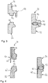
- FIG. 3 an enlarged detail of a longitudinal section through a first embodiment of the two joining areas 36, 50 is shown.
- the joining areas 36, 50 each have a fusible projection 52 (left illustration in FIG Fig. 3 ).
- a weld seam cover 54 protrudes from the housing wall 28 of the base part 24.
- the fusible projections 52 are heated and / or fused or plasticized and pressed together in order to produce a weld seam 56 (right illustration in FIG Fig. 3 ).
- the weld seam cover 54 makes contact upon compression the cover part 22 and thereby covers a joint gap 58. As a result, no melt can escape, so that a clean outer surface is created.
- a second embodiment of the joining areas 30, 50 is shown, which differs from the first embodiment in that the weld seam cover 54 is designed as a tapering top lip 60 (left illustration of FIG Fig. 4 ), which, after being compressed, engages in a slope 62 of the cover part 22 in order to cover the joint gap 58. This creates a surface that is smooth on the outside.
- FIG. 5 an air suspension strut 100 is shown, which has a damper 102, a second air spring component 104 according to the invention and an air spring bellows 106 connecting the damper 102 and the air spring component 104 to one another.
- the air spring component 104 has an additional volume container 108 and a rolling piston 110, which are materially connected to one another by means of hot gas welding.
- the rolling piston 110 is double-walled and has a fastening section 111 for fastening the air suspension bellows 106, an outer wall 112 which serves as a rolling contour for the air suspension bellows 106, and a boundary wall 114. Due to the double-walled design of the rolling piston 110, a switching volume is formed between the outer wall 112 and the delimiting wall 114. The air spring bellows 106 is clamped to the fastening section 111 by means of a clamping ring (not shown). Furthermore, the rolling piston is provided with a central passage 116 for receiving the damper 102. For the radial guidance of the damper 102, the rolling piston 110 has ribs 118 at the end. In the present case, the rolling piston 110 is made in one piece. Furthermore, the rolling piston 110 can also be formed in two parts from a cover part and a rolling piston part, which are materially connected to one another by means of hot gas welding.
- the rolling piston 110 is materially connected to the additional volume container 108 by hot gas welding, as explained above. In particular, these are free
- the end of the outer wall 112 and the free end of the inner delimiting wall 114 are materially connected to the additional volume container 108.
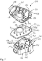
- the additional volume container 108 a cover part 120, a bottom part 122 and a partition wall 124 arranged therebetween.
- the cover part 120 and the base part 122 are approximately pot-shaped and comprise a base section 126, a housing wall 128 and ribs 130 which protrude radially inward from the housing wall 128.
- the partition wall 124 has webs 132 which correspond to the ribs 130 and which protrude on both sides of the partition wall 124 in the axial direction.
- the cover part 120, the partition wall 124 and the base part 122 each have a passage 136 which, in the assembled state, match the passage 116 of the rolling piston 110 in order to form a receptacle for the damper 102.
- the cover part 120, the base part 122 and the partition 124 are materially connected by means of hot gas welding, as explained above.
- the edge sections 138, the borders 139 of the passages 136, the free ends 140 of the ribs 130 and the webs 132 each form a joining area 142.
- the joining areas 142 can be planar or three-dimensional, as in FIG Figures 3 and 4 is shown, be formed.
- a weld seam cover 54 as shown in FIGS Figures 3 and 4 is shown, be arranged.
- the partition wall 124 divides the additional volume container 108 into a first chamber 144 and a second chamber 146.
- the first chamber 144 has a first valve seat 148 introduced into the housing wall 128 and the second chamber 146 has a second valve seat 150 introduced into the housing wall 128.
- switching valves 152 integrated in order to control the switching volume located in the chambers 144, 146.
- the switching volume of the first chamber 144 is, as in FIG Fig. 6 is connected to the switching volume of the rolling piston 110 and thus enables a larger switching volume and thus a greater spread of the air spring stiffness between the various switching positions.
- both the rolling piston 110 and the additional volume container 108 are made from glass fiber reinforced thermoplastic, in particular PA 66 GF 30.
- FIG. 9 Another embodiment of the air spring component 104 is shown which differs from that shown in FIGS Figures 5 to 8
- the air spring component 104 shown differs in that the rolling piston 110 is made of metal, in particular aluminum, with a form-fitting and / or force-fitting connection being used instead of the material connection with the additional volume container 108.
- the rolling piston 110 is connected to the additional volume container 108 by means of an embossing 154.
- the air spring component 14, 104 is distinguished by the material connection of the components made of plastic by means of hot gas welding. As a result, the air spring components 114, 104 meet the requirements placed on pressure-carrying air spring components in terms of tightness, component strength, temperature and resistance to aging.
Landscapes
- Engineering & Computer Science (AREA)
- Mechanical Engineering (AREA)
- General Engineering & Computer Science (AREA)
- Chemical & Material Sciences (AREA)
- Combustion & Propulsion (AREA)
- Fluid-Damping Devices (AREA)
- Vehicle Body Suspensions (AREA)
- Lining Or Joining Of Plastics Or The Like (AREA)
Description
Die vorliegende Erfindung betrifft eine Luftfederkomponente, insbesondere Abrollkolben, Zusatzvolumenbehälter für einen Abrollkolben oder Luftfedertopf.The present invention relates to an air spring component, in particular a rolling piston, an additional volume container for a rolling piston or an air spring pot.
Luftfedern dienen zur Abfederung zweier zueinander beweglicher Fahrzeugteile, aber auch zur Veränderung der Niveaulage eines Fahrzeugs. Typische Luftfedern weisen einen mit Luft gefüllten Luftfederbalg aus Gummi auf, der luftdicht durch ein oberes Abschlusselement und einen Abrollkolben abgeschlossen ist. Das Abschlusselement und der Abrollkolben werden auch als Luftfederkomponenten bezeichnet. Bei einer Belastung rollt sich der Luftfederbalg an der Außenfläche des Abrollkolbens ab. Über den Abrollkolben erfolgt zudem die Anbindung der Luftfeder an einem Fahrzeugteil.Air springs serve to cushion two vehicle parts that can move relative to one another, but also to change the level of a vehicle. Typical air springs have an air-filled air spring bellows made of rubber, which is hermetically sealed by an upper closing element and a rolling piston. The closing element and the rolling piston are also referred to as air spring components. In the event of a load, the air spring rolls on the outer surface of the rolling piston. The air spring is also connected to a vehicle part via the rolling piston.
Die Federwirkung von Luftfedern beruht auf der Kompressibilität von Luft. Somit ist die Federhärte vom Volumen der eingeschlossenen Luft und deren Druck abhängig. Durch Verändern der Luftmenge kann die Niveaulage eingestellt werden.The spring action of air springs is based on the compressibility of air. The spring stiffness is therefore dependent on the volume of the enclosed air and its pressure. The level can be adjusted by changing the amount of air.
Indem das zur Verfügung stehende Volumen vergrößert wird, können die Luftfedereigenschaften verbessert werden. Eine Volumenvergrößerung kann zumeist dadurch erzielt werden, dass die Luftfederkomponenten entsprechend groß ausgebildet werden. Da der zur Verfügung stehende Bauraum für die Luftfederkomponenten oft sehr beschränkt ist, müssen diese für eine vernünftige Volumenausnutzung oft mehrteilig ausgeführt sein.By increasing the available volume, the air spring properties can be improved. An increase in volume can usually be achieved by making the air spring components correspondingly large. Since the space available for the air spring components is often very limited, they often have to be made up of several parts for a sensible use of the volume.
Ferner ist eine mehrteilige Ausgestaltung der Luftfederkomponenten allein schon aus fertigungstechnischen Gründen erforderlich. Denn Luftfederkomponenten werden heutzutage aus Gewichts- und Kostengründen zumeist aus Kunststoff im Spritzgußverfahren oder im Schleudergußverfahren hergestellt. Zur Erhöhung der Steifigkeit und Belastbarkeit eines aus Kunststoff gefertigten Abrollkolbens sind dabei oftmals innenliegende Verstärkungsrippen erforderlich. Die sich dabei ergebenden Hinterschneidungen lassen sich bei einteilig hergestellten Luftfederkomponenten nur schwer oder zumeist gar nicht entformen. Dadurch ist eine mehrteilige Ausgestaltung der Luftfederkomponente notwendig.Furthermore, a multi-part design of the air spring components is necessary for manufacturing reasons alone. Because air spring components are nowadays mostly made of plastic by injection molding or centrifugal casting for reasons of weight and cost. To increase the rigidity and resilience of a plastic roll-off piston internal reinforcement ribs are often required. The resulting undercuts can only be removed from the mold with difficulty or mostly not at all in the case of air spring components manufactured in one piece. As a result, a multi-part design of the air spring component is necessary.
Eine zweiteilige beziehungsweise mehrteilige Ausgestaltung hat jedoch den Nachteil, dass besondere konstruktive Maßnahmen zur Abdichtung und verliersicheren Verbindung der Einzelteile ergriffen werden müssen. Insbesondere ist darauf zu achten, dass an der Fügestelle der beiden Einzelteile eine ausreichende Dichtheit gegeben ist, um eine einwandfreie Funktion der Luftfeder zu gewährleisten.However, a two-part or multi-part design has the disadvantage that special structural measures must be taken to seal and securely connect the individual parts. In particular, it is important to ensure that the joint between the two individual parts is sufficiently tight to ensure that the air spring functions properly.
Ferner geht aus
Darüber hinaus geht aus
Der Erfindung liegt daher die Aufgabe zugrunde, eine Luftfederkomponente, insbesondere eine druckführende Luftfederkomponente zu schaffen, die trotz ihrer Mehrteiligkeit eine ausreichende Dichtheit, Bauteilfestigkeit, Temperatur und Alterungsbeständigkeit aufweist und gleichzeitig kostengünstig in der Herstellung ist. Zur Lösung der Aufgabe wird eine Luftfederkomponente mit den Merkmalen des Anspruchs 1 vorgeschlagen.The invention is therefore based on the object of creating an air spring component, in particular a pressure-bearing air spring component, which, despite its multi-part design, has sufficient tightness, component strength, temperature and aging resistance and at the same time is inexpensive to manufacture. To achieve the object, an air spring component having the features of claim 1 is proposed.
Vorteilhafte Ausgestaltungen der erfindungsgemäßen Luftfederkomponente sind Gegenstand der abhängigen Ansprüche.Advantageous configurations of the air spring component according to the invention are the subject of the dependent claims.
Die erfindungsgemäße Luftfederkomponente umfasst mindestens zwei Bauteile, die korrespondierende Fügebereiche aufweisen, wobei die Fügebereiche stoffschlüssig mittels Heißgasschweißen unter inerter Atmosphäre miteinander verbunden sind, wobei an den Fügebereichen aufschmelzbare Vorsprünge vorgesehen sind und wobei wenigstens eines der Bauteile eine Schweißnahtverdeckung aufweist, die einen Fügespalt abdeckt.The air spring component according to the invention comprises at least two components that have corresponding joining areas, the joining areas being connected to one another by means of hot gas welding under an inert atmosphere, with fusible projections being provided on the joining areas and with at least one of the components having a weld seam cover that covers a joint gap.
Bevorzugt erfolgt der Stoffschluss unter Ausbildung einer Schweißnaht. Die stoffschlüssige Verbindung der beiden Bauteile unter inerter Atmosphäre ermöglicht, eine aus mehreren Bauteilen bestehende druckführende Luftfederkomponente zu erzeugen, die im Bereich der Fügestelle eine ausreichende Dichtheit, Festigkeit sowie Temperatur und Alterungsbeständigkeit aufweist. Ferner gewährleistet die stoffschlüssige Verbindung unter inerter Atmosphäre eine große gestalterische Freiheit der Fügebereiche bzw. der Verbindungsstellen. Die Fügebereiche können sowohl am äußeren Umfang, insbesondere an den Randabschnitten des Bauteils als auch im Inneren des Bauteils angeordnet sein. Ferner können die Fügebereiche eben ausgebildet sein, aber auch eine dreidimensionale Ausgestaltung aufweisen. Zudem ist vorteilhaft keine Nachbearbeitung der Fügebereiche vor dem Fügen erforderlich. Des Weiteren schützt die inerte Atmosphäre vor einer Verunreinigung der Fügebereiche, da eine Oxidation und/oder Reaktion der zu fügenden Bereiche verhindert wird. Dadurch weist die Schweißnaht eine hohe Festigkeit und Dichtheit auf. Die Rippen und Stege sorgen für eine ausreichende Stabilität und Steifigkeit der Bauteile bzw. der Luftfederkomponente.The material connection preferably takes place with the formation of a weld seam. The cohesive connection of the two components under an inert atmosphere makes it possible to produce a pressure-bearing air spring component consisting of several components, which has sufficient tightness, strength and temperature and aging resistance in the area of the joint. Furthermore, the cohesive connection under an inert atmosphere ensures great design freedom of the joining areas or the connection points. The joining areas can be arranged both on the outer circumference, in particular on the edge sections of the component, and also inside the component. Furthermore, the joining areas can be flat, but also have a three-dimensional design. In addition, there is advantageously no need for post-processing of the joining areas before joining. In addition, the inert atmosphere protects against contamination of the joining areas, since oxidation and / or reaction of the areas to be joined is prevented. As a result, the weld seam has a high level of strength and tightness. The ribs and webs ensure sufficient stability and rigidity of the components or the air spring component.
In einer vorteilhaften Ausgestaltung erfolgt der Stoffschluss durch Erwärmen und/oder Aufschmelzen und anschließendem Verpressen der Fügebereiche unter inerter Atmosphäre. Bevorzugt wird dabei eine Schweißnaht ausgebildet. Vorteilhaft wird als inerte Atmosphäre Stickstoff verwendet. Weiterhin vorteilhaft wird die inerte Atmosphäre in einer Umhausung erzeugt.In an advantageous embodiment, the material bond takes place by heating and / or melting and subsequent pressing of the joining areas under an inert atmosphere. A weld seam is preferably formed. Nitrogen is advantageously used as the inert atmosphere. The inert atmosphere is also advantageously generated in an enclosure.
Die Fügebereiche sind mittels Heißgasschweißen miteinander verbunden. Durch Heißgasschweißen lassen sich Bauteile aus Kunststoff, insbesondere aus glasfaserverstärktem Kunststoff, derart stoffschlüssig verbinden, dass die Anforderungen für druckführende Luftfederkomponenten, wie beispielsweise Dichtheit, Bauteilfestigkeit, Temperatur und/oder Alterungsbeständigkeit, erfüllt werden. Beim Heißgasschweißen werden die beiden zu fügenden Bauteile, insbesondere deren Fügebereiche durch Heißgas erwärmt und/oder ausgeschmolzen bzw. plastifiziert und anschließend unter Druck miteinander gefügt. Die Erwärmung beziehungsweise Plastifizierung erfolgt beim Heißgasschweißen kontaktlos über Heißgas. Vorteilhaft bildet dabei das Heißgas die inerte Atmosphäre. Weiterhin vorteilhaft wird beim Heißgasschweißen Stickstoff als Heißgas verwendet. Durch die Verwendung von Stickstoff als Arbeitsgas werden die Bauteile während des Erwärmens beziehungsweise Plastifizierens vor einer Oxidation und/oder Reaktion geschützt.The joining areas are connected to one another by means of hot gas welding. By means of hot gas welding, components made of plastic, in particular made of glass-fiber reinforced plastic, can be connected in such a way that the requirements for pressure-bearing air spring components, such as tightness, component strength, temperature and / or aging resistance, are met. During hot gas welding, the two components to be joined, in particular their Joining areas heated by hot gas and / or melted or plasticized and then joined together under pressure. In hot gas welding, the heating or plasticization takes place without contact using hot gas. The hot gas advantageously forms the inert atmosphere. Nitrogen is also advantageously used as the hot gas in hot gas welding. By using nitrogen as the working gas, the components are protected from oxidation and / or reaction during heating or plasticizing.
Beim Heißgasschweißen werden die zu fügenden Bauteile in Haltevorrichtungen aufgenommen und zueinander beabstandet positioniert. Anschließend werden die Fügebereiche mittels eines heißen Gases, insbesondere Stickstoff, erweicht und/oder aufgeschmolzen beziehungsweise plastifiziert. Vorteilhaft wird das heiße Gas über Düsen auf die Fügebereiche aufgebracht. Danach werden die beiden Bauteile beziehungsweise die erwärmten oder plastifizierten Fügebereiche miteinander unter Druck verpresst. Durch Halten dieser Position sowie einer Abkühlung der erwärmten beziehungsweise plastifizierten Fügebereiche erfolgt durch Erstarren ein Stoffschluss zwischen den beiden Bauteilen unter Ausbildung einer Schweißnaht.During hot gas welding, the components to be joined are held in holding devices and positioned at a distance from one another. The joining areas are then softened and / or melted or plasticized by means of a hot gas, in particular nitrogen. The hot gas is advantageously applied to the joining areas via nozzles. Then the two components or the heated or plasticized joining areas are pressed together under pressure. By holding this position and cooling the heated or plasticized joint areas, solidification occurs a material bond between the two components with the formation of a weld seam.
In einer alternativen Ausgestaltung erfolgt das Erwärmen mittels Infrarot, Spiegelaufheizung und/oder Induktion. Vorteilhaft erfolgt die Erwärmung entweder unter Vakuum oder unter Einsatz eines inerten Arbeitsgases, insbesondere Stickstoff, in einer entsprechenden Umhausung.In an alternative embodiment, the heating takes place by means of infrared, mirror heating and / or induction. The heating is advantageously carried out either under vacuum or using an inert working gas, in particular nitrogen, in a suitable housing.
Vorteilhaft ragen die Rippen und/oder Stege von einer Gehäusewand der Bauteile radial nach innen und/oder außen ab. Dadurch kann das Bauteil so gestaltet werden, dass der Fügebereich beziehungsweise die Verbindungsstelle sowohl am äußeren Umfang als auch am inneren Umfang des Bauteils angeordnet ist.The ribs and / or webs advantageously protrude radially inward and / or outward from a housing wall of the components. As a result, the component can be designed in such a way that the joining area or the connection point is arranged both on the outer circumference and on the inner circumference of the component.
Die Stege und/oder Rippen können eine näherungsweise T-förmige Grundform aufweisen. Hierdurch kann die Oberfläche der Fügebereiche vergrößert werden.The webs and / or ribs can have an approximately T-shaped basic shape. This allows the surface of the joining areas to be enlarged.
Erfindungsgemäß sind an den Fügebereichen aufschmelzbare Vorsprünge vorgesehen. Hierbei können die Fügebereiche direkt während des Spritzgussverfahrens hergestellt sein. Ferner können die Fügebereiche eben sein, aber auch eine dreidimensionale Ausgestaltung aufweisen. Die aufschmelzbaren Vorsprünge werden entweder durch Heißgas, Infrarot, Spiegelaufheizung und/oder Induktion erwärmt und/oder plastifiziert beziehungsweise aufgeschmolzen und bilden durch Verpressen und Erstarren eine Schweißnaht aus.According to the invention, meltable projections are provided on the joining areas. The joining areas can be produced directly during the injection molding process. Furthermore, the joining areas can be flat, but also have a three-dimensional design. The meltable projections are either heated and / or plasticized or melted by hot gas, infrared, mirror heating and / or induction and form a weld seam by pressing and solidifying.
Ferner erfindungsgemäß weist wenigstens eines der Bauteile eine Schweißnahtverdeckung auf, die einen Fügespalt abdeckt. Vorteilhaft ist die Schweißnahtverdeckung als eine umlaufende Verdecklippe ausgebildet. Die Verdecklippe ragt dabei von einem der Bauteile, vorzugsweise von dessen Gehäusewand ab. Beim Verpressen der beiden Bauteile kontaktiert die Verdecklippe das andere Bauteil bzw. dessen Gehäusewand und verdeckt dadurch den Fügespalt. Somit verhindert die Verdecklippe einen Austritt der plastifizierten beziehungsweise aufgeschmolzenen Fügebereiche während des Verpressens. Dadurch ist es nicht mehr erforderlich, die Schweißnaht aufwändig nachzubearbeiten, da eine saubere Außenfläche der Luftfederkomponente geschaffen wird.Furthermore, according to the invention, at least one of the components has a weld seam cover which covers a joint gap. The weld seam covering is advantageously designed as a circumferential folding top lip. The top lip protrudes from one of the components, preferably from its housing wall. When the two components are pressed together, the top lip makes contact with the other component or its housing wall, thereby covering the joint gap. Thus, the hood lip prevents An exit of the plasticized or melted joint areas during the pressing. As a result, it is no longer necessary to rework the weld seam in a complex manner, since a clean outer surface of the air spring component is created.
In einer vorteilhaften Ausgestaltung ragt die Schweißnahtverdeckung vom ersten Bauteil ab und liegt in einer korrespondierenden Aussparung am zweiten Bauteil ein. Vorteilhaft ist die Schweißnahtverdeckung als spitz zulaufende Verdecklippe ausgebildet, die in eine korrespondierende Schräge am gegenüberliegenden bzw. zweiten Bauteil während des Verpressens eingreift. Vorteilhaft wird hierdurch eine weitestgehend glatte Außenfläche geschaffen.In an advantageous embodiment, the weld seam covering protrudes from the first component and is located in a corresponding recess on the second component. The weld seam covering is advantageously designed as a tapering hood lip which engages in a corresponding bevel on the opposite or second component during the pressing. This advantageously creates a largely smooth outer surface.
In einer vorteilhaften Ausgestaltung weist die Luftfederkomponente ein Bodenteil und ein Deckelteil auf, die stoffschlüssig zu einem Luftfedertopf verbunden sind. Weiterhin vorteilhaft sind die Teile unter inerter Atmosphäre, vorzugsweise mittels Heißgasschweißen stoffschlüssig verbunden.In an advantageous embodiment, the air spring component has a base part and a cover part, which are materially connected to form an air spring cup. The parts are also advantageously materially connected under an inert atmosphere, preferably by means of hot gas welding.
Ferner kann die Luftfederkomponente ein Bodenteil, ein Deckelteil und eine dazwischen angeordnete Trennwand aufweisen, wobei das Deckelteil und das Bodenteil mittels der Trennwand stoffschlüssig zu einem Zusatzvolumenbehälter verbunden sind. Die Teile können unter inerter Atmosphäre, vorzugsweise mittels Heißgasschweißen stoffschlüssig verbunden sein. Vorteilhaft teilt die Trennwand den Zusatzvolumenbehälter in mehrere Schaltvolumen, die über in das Boden- und Deckelteil integrierte Schaltventile gesteuert werden können. Dadurch kann die Luftfedersteifigkeit gespreizt werden. Ferner kann die als Zusatzvolumenbehälter ausgebildete Luftfederkomponente mehrere Trennwände aufweisen, die eine Unterteilung in mehrere Kammern ermöglichen.Furthermore, the air spring component can have a base part, a cover part and a partition arranged between them, the cover part and the base part being materially connected by means of the partition to form an additional volume container. The parts can be materially connected in an inert atmosphere, preferably by means of hot gas welding. The partition wall advantageously divides the additional volume container into several switching volumes, which can be controlled via switching valves integrated in the base and cover part. This allows the air spring stiffness to be spread. Furthermore, the air spring component, which is designed as an additional volume container, can have a plurality of partition walls which enable a subdivision into a plurality of chambers.
In vorteilhafter Ausgestaltung weist die Luftfederkomponente ein Deckelteil und ein Abrollkolbenteil auf, die stoffschlüssig zu einem Abrollkolben verbunden sind. Vorteilhaft sind die Teile unter inerter Atmosphäre, vorzugsweise mittels Heißgasschweißen stoffschlüssig verbunden. Der Abrollkolben, insbesondere das Abrollkolbenteil, kann doppelwandig ausgeführt sein, um so eine mit Luft gefüllte Kammer zu bilden, die mit einer Kammer des Zusatzvolumenbehälters verbunden sein kann. Dadurch wird ein noch größeres Schaltvolumen und damit einhergehend eine große Spreizung der Luftfedersteifigkeit ermöglicht. Der Abrollkolben ist vorteilhaft derart ausgestaltet, dass ein Dämpfer aufgenommen werden kann.In an advantageous embodiment, the air spring component has a cover part and a rolling piston part, which are materially connected to form a rolling piston. The parts are advantageously materially bonded in an inert atmosphere, preferably by means of hot gas welding. The rolling piston, in particular the rolling piston part, can be double-walled in order to form an air-filled chamber that can be connected to a chamber of the additional volume container. This creates an even larger switching volume and is associated with it allows a large spread of the air spring stiffness. The rolling piston is advantageously designed in such a way that a damper can be received.
Der Zusatzvolumenbehälter ist mit einem Abrollkolben stoffschlüssig, formschlüssig und/oder kraftschlüssig verbunden. Vorteilhaft sind sowohl Innen- als auch Außenwand des Abrollkolbens stoffschlüssig mit dem Zusatzvolumenbehälter verbunden. Dies ist insbesondere dann möglich, wenn der Abrollkolben ebenfalls aus Kunststoff hergestellt ist. Eine kraftschlüssige Verbindung des Abrollkolbens mit dem Zusatzvolumenbehälter erfolgt dann, wenn dieser aus einem anderen Material, wie beispielsweise Metall hergestellt ist. Insbesondere erfolgt die formschlüssige Verbindung durch eine Verprägung des Abrollkolbens mit dem Zusatzvolumenbehälter. Der Abrollkolben kann einteilig als auch mehrteilig ausgebildet sein.The additional volume container is materially, positively and / or non-positively connected to a rolling piston. Both the inner and outer walls of the rolling piston are advantageously materially connected to the additional volume container. This is possible in particular when the rolling piston is also made of plastic. A non-positive connection of the rolling piston with the additional volume container takes place when it is made of a different material, such as metal. In particular, the form-fitting connection takes place by stamping the rolling piston with the additional volume container. The rolling piston can be designed in one piece or in several pieces.
Vorteilhaft sind die Bauteile aus thermoplastischen Kunststoff, insbesondere aus glasfaserverstärktem thermoplastischen Kunststoff hergestellt. Weiterhin vorteilhaft ist der Abrollkolben aus Metall oder aus thermoplastischen Kunststoff, insbesondere aus glasfaserverstärktem thermoplastischen Kunststoff hergestellt. Als thermoplastischer Kunststoff wird bevorzugt PA 66 GF 30 verwendet. Die aus Kunststoff gefertigten Bauteile tragen zu einer Gewichtsreduzierung und damit einhergehend zu einer Kraftstoffeinsparung bei. Als Metall wird vorteilhaft Aluminium verwendet, das ebenfalls ein vergleichsweise geringes Gewicht aufweist.The components are advantageously made from thermoplastic material, in particular from glass fiber-reinforced thermoplastic material. The rolling piston is also advantageously made from metal or from thermoplastic material, in particular from glass fiber-reinforced thermoplastic material. The preferred thermoplastic material is PA 66 GF 30. The components made of plastic help to reduce weight and thus save fuel. The metal used is advantageously aluminum, which also has a comparatively low weight.
Nachfolgend wird die erfindungsgemäße Luftfederkomponente anhand der beigefügten schematischen Zeichnungen näher erläutert. Hierbei zeigen:
- Fig. 1
- einen Längsschnitt durch eine Luftfeder mit einer als Luftfedertopf ausgebildeten erfindungsgemäßen Luftfederkomponente;
- Fig. 2
- eine perspektivische Darstellung des Luftfedertopfs mit einem Deckelteil und einem Bodenteil;
- Fig. 3
- einen vergrößerten Ausschnitt eines Längsschnitts durch einen Fügebereich gemäß einer erste Ausführungsform;
- Fig. 4
- einen vergrößerten Ausschnitt eines Längsschnitts durch einen Fügebereich gemäß einer zweiten Ausführungsform;
- Fig. 5
- einen Längsschnitt durch ein Luftfederbein mit einer als Abrollkolben und einem Zusatzvolumenbehälter ausgebildeten erfindungsgemäßen Luftfederkomponente;
- Fig. 6
- einen Längsschnitt durch die als Abrollkolben und Zusatzvolumenbehälter ausgebildete Luftfederkomponente;
- Fig. 7
- eine perspektivische Darstellung der einzelnen Bauteile des Zusatzvolumenbehälters;
- Fig. 8
- eine perspektivische Darstellung des als Abrollkolben und Zusatzvolumenbehälters ausgebildeten Luftfederkomponente; und
- Fig. 9
- einen Längsschnitt durch eine als Zusatzvolumenbehälter ausgebildete erfindungsgemäße Luftfederkomponente und einen Abrollkolben aus Metall, die mittels Prägen miteinander verbunden sind.
- Fig. 1
- a longitudinal section through an air spring with an air spring component according to the invention designed as an air spring cup;
- Fig. 2
- a perspective view of the air spring cup with a cover part and a bottom part;
- Fig. 3
- an enlarged detail of a longitudinal section through a joining area according to a first embodiment;
- Fig. 4
- an enlarged detail of a longitudinal section through a joining area according to a second embodiment;
- Fig. 5
- a longitudinal section through an air spring strut with an air spring component according to the invention designed as a rolling piston and an additional volume container;
- Fig. 6
- a longitudinal section through the air spring component designed as a rolling piston and additional volume container;
- Fig. 7
- a perspective view of the individual components of the additional volume container;
- Fig. 8
- a perspective view of the air spring component designed as a rolling piston and additional volume container; and
- Fig. 9
- a longitudinal section through an air spring component designed as an additional volume container according to the invention and a rolling piston made of metal, which are connected to one another by means of stamping.
In
Die Luftfeder 10 weist einen Abrollkolben 12, eine erfindungsgemäße Luftfederkomponente 14, die vorliegend als Luftfedertopf 16 ausgebildet ist, und einen Luftfederbalg 18, der mit einem ersten freien Ende an dem Abrollkolben 12 unter Ausbildung einer Rollfalte und mit einem zweiten freien Ende an dem Luftfedertopf 16 angebracht ist. Der Luftfederbalg 18 bildet dabei einen mit Luft gefüllten Luftfederinnenraum 20 aus. Während eines Ein- und Ausfederungsvorgangs rollte der Luftfederbalg 16 an der Außenseite des Abrollkolbens 12 ab.The
Wie aus
Das Bodenteil 24 ist dabei näherungsweise topfförmig ausgebildet und weist einen Bodenabschnitt 26 und eine den Bodenabschnitt 26 umgebende Gehäusewand 28 auf. Von der Gehäusewand 28 erstrecken sich radial nach innen eine Vielzahl an Rippen 30a, 30b, die im Querschnitt näherungsweise T-förmig ausgebildet und stoffschlüssig mit dem Bodenabschnitt 26 und der Gehäusewand 28 verbunden sind. Wie insbesondere in
Das Deckelteil 22 ist aus einem Bodenabschnitt 38 gebildet, der zentral von einer Öffnung 40 durchbrochen ist, die, wie in
Beim Heißgasschweißen werden die korrespondierenden Fügebereiche 36, 50 erwärmt und/oder aufgeschmolzen bzw. plastifiziert und anschließend zusammengedrückt. Nach dem Erstarren der Fügebereiche 36, 50 erfolgt unter Ausbildung einer nicht dargestellten Schweißnaht eine stoffschlüssige Verbindung von Deckelteil 22 und Bodenteil 24. Beim Heißgasschweißen werden die Fügebereiche 36, 50 mittels eines Heißgases erwärmt und/oder aufgeschmolzen bzw. plastifiziert, wobei bevorzugt Stickstoff als Arbeitsgas verwendet wird. Vorliegend sind die Fügebereiche 36, 50 eben ausgebildet.During hot gas welding, the corresponding joining
In
In
In
Wie insbesondere in den
Der Abrollkolben 110 ist vorliegend doppelwandig ausgeführt und weist einen Befestigungsabschnitt 111 zum Befestigen des Luftfederbalgs 106, eine Außenwand 112, die als Abrollkontur für den Luftfederbalg 106 dient, und eine Begrenzungswand 114 auf. Durch die doppelwandige Ausgestaltung des Abrollkolbens 110 wird zwischen der Außenwand 112 und der Begrenzungswand 114 ein Schaltvolumen gebildet. Der Luftfederbalg 106 wird mittels eines nicht dargestellten Klemmringes an dem Befestigungsabschnitt 111 verklemmt. Ferner ist der Abrollkolben mit einem zentralen Durchgang 116 zur Aufnahme des Dämpfers 102 versehen. Zur radialen Führung des Dämpfers 102 weist der Abrollkolben 110 endseitig Rippen 118 auf. Vorliegend ist der Abrollkolben 110 einteilig ausgeführt. Ferner kann der Abrollkolben 110 auch zweteilig aus einem Deckelteil und einem Abrollkolbenteil gebildet sein, die stoffschlüssig miteinander mittels Heißgasschweißen verbunden sind.In the present case, the rolling
Der Abrollkolben 110 ist mit dem Zusatzvolumenbehälter 108 stoffschlüssig durch Heißgasschweißen, wie zuvor erläutert, verbunden. Insbesondere sind das freie Ende der Außenwand 112 und das freie Ende der inneren Begrenzungswand 114 stoffschlüssig mit dem Zusatzvolumenbehälter 108 verbunden.The rolling
Der Zusatzvolumenbehälter 108 weist gemäß
Das Deckelteil 120, das Bodenteil 122 und die Trennwand 124 sind stoffschlüssig mittels Heißgasschweißen, wie zuvor erläutert verbunden. Die Randabschnitte 138, die Umrandungen 139 der Durchgänge 136, die freien Enden 140 der Rippen 130 bzw. der Stege 132 bilden jeweils einen Fügebereich 142. Die Fügebereiche 142 können eben oder dreidimensional, wie in den
Die Trennwand 124 unterteilt den Zusatzvolumenbehälter 108 in eine erste Kammer 144 und in eine zweite Kammer 146. Die erste Kammer 144 weist einen in die Gehäusewand 128 eingebrachten ersten Ventilsitz 148 und die zweite Kammer 146 weist einen in die Gehäusewand 128 eingebrachten zweiten Ventilsitz 150 auf. In die Ventilsitze 148, 150 sind, wie in
In der in den
In
Die erfindungsgemäße Luftfederkomponente 14, 104 zeichnet sich durch die stoffschlüssige Verbindung der aus Kunststoff hergestellten Bauteile mittels Heißgasschweißen aus. Dadurch erfüllen die Luftfederkomponenten 114, 104 die an druckführende Luftfederbauteile gestellten Anforderungen hinsichtlich der Dichtheit, Bauteilfestigkeit, Temperatur und Alterungsbeständigkeit.The
- 1010
- LuftfederAir spring
- 1212
- AbrollkolbenRolling piston
- 1414th
- LuftfederkomponenteAir suspension component
- 1616
- LuftfedertopfAir spring cup
- 1818th
- LuftfederbalgAir bag
- 2020th
- LuftfederinnenraumAir spring interior
- 2222nd
- DeckelteilCover part
- 2424
- BodenteilBottom part
- 2626th
- BodenabschnittFloor section
- 2828
- GehäusewandHousing wall
- 30a30a
- kurze Rippeshort rib
- 30b30b
- lange Rippelong rib
- 3232
- RandabschnittEdge section
- 3434
- freies Endefree end
- 3636
- erster Fügebereichfirst joining area
- 3838
- BodenabschnittFloor section
- 4040
- Öffnungopening
- 4242
- WandungWall
- 44a44a
- kurzer Stegshort bridge
- 44b44b
- langer Steglong bridge
- 4646
- RandabschnittEdge section
- 4848
- freies Endefree end
- 5050
- zweiter Fügebereichsecond joining area
- 5252
- aufschmelzbarer Vorsprungmeltable protrusion
- 5454
- SchweißnahtabdeckungWeld seam cover
- 5656
- SchweißnahtWeld
- 5858
- FügespaltJoint gap
- 6060
- VerdecklippeConvertible top lip
- 6262
- SchrägeSlant
- 100100
- LuftfederbeinAir strut
- 102102
- Dämpfermute
- 104104
- LuftfederkomponenteAir suspension component
- 106106
- LuftfederbalgAir bag
- 108108
- ZusatzvolumenbehälterAdditional volume container
- 110110
- AbrollkolbenRolling piston
- 111111
- BefestigungsabschnittFastening section
- 112112
- AußenwandOuter wall
- 114114
- BegrenzungswandBoundary wall
- 116116
- DurchgangPassage
- 118118
- RippenRibs
- 120120
- DeckelteilCover part
- 122122
- BodenteilBottom part
- 124124
- Trennwandpartition wall
- 126126
- BodenabschnittFloor section
- 128128
- GehäusewandHousing wall
- 130130
- Ripperib
- 132132
- Stegweb
- 136136
- DurchgangPassage
- 138138
- RandabschnittEdge section
- 139139
- UmrandungBorder
- 140140
- freies Endefree end
- 142142
- FügebereichJoining area
- 144144
- erste Kammerfirst chamber
- 146146
- zweite Kammersecond chamber
- 148148
- erster Ventilsitzfirst valve seat
- 150150
- zweiter Ventilsitzsecond valve seat
- 152152
- SchaltventilSwitching valve
- 154154
- VerprägungStamping
Claims (11)
- Air spring component (14, 104), in particular a rolling piston (110), an additional volume container (108) for a rolling piston or an air spring pot (16), the air spring component having at least two components which have corresponding joint regions (36, 50, 142), the joint regions (36, 50, 142) being joined to one another by material closure by means of hot gas welding in an inert atmosphere, wherein fusible projections (52) are provided on the joint regions (36, 50, 142), and at least one of the components having a weld seam covering (54) which covers a joint gap (58).
- Air spring component according to claim 1, characterized in that the material closure is effected by heating and/or melting and subsequent pressing of the joining regions (36, 50, 142) under an inert atmosphere.
- Air spring component according to one of claims 1 or 2, characterized in that the joint regions (36, 50, 142) are formed from corresponding edge sections (138), ribs (30a, 30b, 118) and/or bars (44a, 44b, 132) of the components.
- Air spring component according to claim 3, characterized in that the ribs (30a, 30b, 118) and/or bars (44a, 44b, 132) project radially inwards and/or outwards from a housing wall (28, 128) of the components.
- Air spring component according to claim 3 or 4, characterized in that the bars (44a, 44b, 132) and/or ribs (30a, 30b, 118) have an approximately T-shaped basic form.
- Air spring component according to any one of claims 1 to 5, characterized in that the weld seam covering (54) projects from the first component and is located in a corresponding recess (62) on the second component.
- Air spring component according to any one of claims 1 to 6, characterized by a base part (24) and a cover part (22), which are connected by material closure to form an air spring pot (16).
- An air spring component according to any one of claims 1 to 7, characterized by a base part (122), a cover part (120) and a partition (124) arranged therebetween, wherein the cover part (120) and the base part (122) are connected by material closure by means of the partition (124) to form an additional volume container (108).
- Air spring component according to any one of claims 1 to 8, characterized by a cover part and a roll-off piston part, which are connected by material closure to form a roll-off piston (110).
- Air spring component according to claim 9, characterized in that the additional volume container (108) is connected to the roll-off piston (110) by material closure, by form closure and/or by force closure.
- Air spring component according to any one of claims 1 to 10, characterized in that the components are made of thermoplastic, in particular glass-fiberreinforced thermoplastic.
Applications Claiming Priority (2)
| Application Number | Priority Date | Filing Date | Title |
|---|---|---|---|
| DE102013113737.7A DE102013113737A1 (en) | 2013-12-10 | 2013-12-10 | Air suspension component |
| PCT/EP2014/075576 WO2015086315A1 (en) | 2013-12-10 | 2014-11-25 | Pneumatic spring component |
Publications (2)
| Publication Number | Publication Date |
|---|---|
| EP3080477A1 EP3080477A1 (en) | 2016-10-19 |
| EP3080477B1 true EP3080477B1 (en) | 2021-02-24 |
Family
ID=52003741
Family Applications (1)
| Application Number | Title | Priority Date | Filing Date |
|---|---|---|---|
| EP14806218.5A Active EP3080477B1 (en) | 2013-12-10 | 2014-11-25 | Pneumatic spring component |
Country Status (6)
| Country | Link |
|---|---|
| US (1) | US10161472B2 (en) |
| EP (1) | EP3080477B1 (en) |
| JP (1) | JP2017502220A (en) |
| CN (1) | CN105814334A (en) |
| DE (1) | DE102013113737A1 (en) |
| WO (1) | WO2015086315A1 (en) |
Families Citing this family (10)
| Publication number | Priority date | Publication date | Assignee | Title |
|---|---|---|---|---|
| DE102015100281A1 (en) * | 2015-01-09 | 2016-07-14 | Trelleborgvibracoustic Gmbh | Composite component and air spring component with such a composite component |
| US10752070B2 (en) * | 2015-07-01 | 2020-08-25 | Firestone Industrial Products Company, Llc | Clamping plates and gas spring assemblies as well as suspension systems and methods including same |
| WO2018163462A1 (en) * | 2017-03-07 | 2018-09-13 | 株式会社ショーワ | Suspension |
| EP3619061B1 (en) * | 2017-05-05 | 2021-06-02 | Volvo Truck Corporation | Method for determining aging of a vehicle suspension arrangement |
| US10842291B2 (en) * | 2018-01-16 | 2020-11-24 | Yos Soetanto Theosabrata | Mattress construction with self inflated air spring |
| DE102018211118A1 (en) * | 2018-07-05 | 2020-01-09 | Thyssenkrupp Bilstein Gmbh | Damper device, method for producing a damper device |
| DE102019104714A1 (en) * | 2019-02-25 | 2020-08-27 | Vibracoustic Ag | Air suspension module |
| DE102019130989B8 (en) * | 2019-11-15 | 2023-07-20 | Vibracoustic Se | air spring component |
| DE102020134375A1 (en) | 2020-12-21 | 2022-06-23 | Vibracoustic Se | Component in particular for an air spring, an air spring strut, an air spring damper or a top mount housing and method for producing the component |
| DE102022112611A1 (en) | 2022-05-19 | 2023-11-23 | Vibracoustic Se | Device for holding at least two valves within a component and component with the device |
Citations (19)
| Publication number | Priority date | Publication date | Assignee | Title |
|---|---|---|---|---|
| JPH0594547U (en) * | 1992-05-21 | 1993-12-24 | 豊生ブレーキ工業株式会社 | Pressure vessel for air suspension |
| US5298713A (en) * | 1991-06-25 | 1994-03-29 | L'air Liquide, Societe Anonyme Pour L'etude Et L'exploitation Des Procedes Georges | Process for welding thermoplastic materials with projection of hot gas |
| DE19651387A1 (en) | 1996-12-11 | 1998-06-18 | Zahnradfabrik Friedrichshafen | container |
| FR2713540B1 (en) | 1993-12-13 | 1999-11-26 | Orbey Plastiques Ind | Welding joint for hollow parts. |
| JP3169153B2 (en) | 1993-12-28 | 2001-05-21 | トヨタ自動車株式会社 | How to join plastic members |
| DE10163552A1 (en) | 2001-12-21 | 2003-07-03 | Volkswagen Ag | Motor vehicle with variably adjustable gas suspension and damping |
| DE10216175C1 (en) | 2002-04-12 | 2003-07-24 | Stiebel Eltron Gmbh & Co Kg | Plastic vessel or pipe has internal and external casings bonded by friction-welding their differing plastic materials together in single operation |
| DE10250751A1 (en) * | 2002-10-31 | 2004-05-19 | Hans Georg Schulz | Method for welding plastic parts, in particular for connecting plastic parts along a welding line |
| DE102004015881A1 (en) | 2003-04-09 | 2004-12-23 | Aisan Kogyo K.K., Obu | Resin inlet manifold |
| EP1602468A2 (en) | 2004-05-26 | 2005-12-07 | Toyota Boshoku Kabushiki Kaisya | Bonding structure for surge tank, surge tank and intake manifold |
| DE102004061989A1 (en) | 2004-12-23 | 2006-07-06 | Continental Aktiengesellschaft | Pneumatic spring for e.g. passenger car, has cover manufactured as single-piece die cast component from plastic material and provided with reinforcement sleeve in area of clamping shaft, where sleeve is made from metal e.g. ferrous metal |
| DE102006010815A1 (en) | 2006-03-07 | 2007-09-13 | Geiger Technik Gesellschaft mit beschränkter Haftung | Thermoplastic housing of pressurized component useful as a reservoir and supply container, exhibits a cavity, which is completely surrounded by openings, wall surfaces lying opposite with one another, and a wall cross-section |
| DE102007026826A1 (en) | 2007-06-06 | 2008-12-11 | Mann + Hummel Gmbh | intake system |
| DE102007035640A1 (en) | 2007-07-27 | 2009-01-29 | Lkh-Kunststoffwerk Gmbh & Co. Kg | plunger |
| JP2009127682A (en) * | 2007-11-21 | 2009-06-11 | Fukoku Co Ltd | Air spring |
| EP2153977A2 (en) | 2008-08-11 | 2010-02-17 | ElringKlinger AG | Assembly with plastic sections welded together and method for their manufacture |
| DE102008048793A1 (en) | 2008-09-24 | 2010-03-25 | Mann + Hummel Gmbh | Method for manufacturing plastic oil pan of thermoplastic, particularly for internal-combustion engine or gear, involves welding oil pan that is made of multiple individual units at fusion zones |
| US8186657B2 (en) | 2007-09-06 | 2012-05-29 | Firestone Industrial Products Company, Llc | Air spring modular piston |
| JP4948004B2 (en) | 2006-03-16 | 2012-06-06 | 東京濾器株式会社 | Vibration welding structure between resin case and resin cover |
Family Cites Families (27)
| Publication number | Priority date | Publication date | Assignee | Title |
|---|---|---|---|---|
| DE3436664A1 (en) * | 1983-10-07 | 1985-05-02 | Bridgestone Corp., Tokio/Tokyo | DIAPHRAGM AIR SPRING |
| DE3609775A1 (en) * | 1985-03-26 | 1986-11-27 | S.E.A. Studiengesellschaft für Energiespeicher und Antriebssysteme Ges.m.b.H., Mürzzuschlag | Device for the integral bonding of parts having thermoplastic at least in the region of the bonding points |
| US4787607A (en) * | 1986-09-24 | 1988-11-29 | The Firestone Tire & Rubber Company | Air spring having internal sealing band and method of installing same |
| US4787606A (en) * | 1987-06-17 | 1988-11-29 | The Firestone Tire & Rubber Company | Beadless air spring |
| US5180145A (en) * | 1991-05-30 | 1993-01-19 | Bridgestone Corporation | Vibration damping device |
| US5332070A (en) * | 1993-04-21 | 1994-07-26 | Honeywell Inc. | Three parameter viscous damper and isolator |
| JPH07133840A (en) * | 1993-11-11 | 1995-05-23 | Bridgestone Corp | Device using electroviscous fluid |
| US5449150A (en) * | 1993-11-29 | 1995-09-12 | Bridgestone Corporation | Vibration damping device with an electrode and having rolling lobes of different radii |
| JPH08230044A (en) * | 1995-02-27 | 1996-09-10 | Aisamu:Kk | Method and apparatus for welding synthetic resin material |
| SE9701384L (en) * | 1997-04-15 | 1998-03-09 | United Parts Laereda Ab | Ways to paint and join two components using powder paint |
| DE50011684D1 (en) * | 1999-10-15 | 2005-12-29 | Freudenberg Carl Kg | AIR SPRING ARRANGEMENT |
| DE10338939B3 (en) * | 2003-08-22 | 2005-02-03 | Continental Aktiengesellschaft | Pneumatic spring and damper unit for vehicle has overflow throttles in the cylinder housing between damper cavities |
| DE10358792B4 (en) * | 2003-12-12 | 2008-08-28 | Carl Freudenberg Kg | air spring |
| JP2005231172A (en) * | 2004-02-19 | 2005-09-02 | Denso Corp | Resin welding apparatus |
| DE102004031873B3 (en) * | 2004-04-22 | 2005-11-17 | Zf Friedrichshafen Ag | Roll-off tube for a pneumatic spring rolling bellows |
| DE102004059764C5 (en) * | 2004-12-11 | 2013-06-06 | Continental Teves Ag & Co. Ohg | Air spring and damper unit |
| DE102004059765A1 (en) * | 2004-12-11 | 2006-07-06 | Continental Aktiengesellschaft | Wheel-guiding air spring and damper unit |
| JP2007313792A (en) * | 2006-05-26 | 2007-12-06 | Nidec Sankyo Corp | Resin molded article and method for manufacturing the same |
| ITTO20060083U1 (en) * | 2006-05-31 | 2007-12-01 | Gomma C F Spa | PISTON OF AN AIR SPRING FOR A ASSEMBLED MOTOR VEHICLE |
| DE102007026163A1 (en) * | 2007-06-04 | 2008-12-11 | Bielomatik Leuze Gmbh + Co Kg | Method and device for melting a thermoplastic material, in particular for welding plastic parts |
| CN101469753A (en) * | 2008-07-15 | 2009-07-01 | 江苏大学 | Air spring for automobile |
| US20120153550A1 (en) | 2009-08-19 | 2012-06-21 | Sigirtmac Tayfun | Bumper for air spring |
| DE102010037096A1 (en) * | 2010-08-20 | 2012-02-23 | Continental Teves Ag & Co. Ohg | Air strut with elastic piston bearing |
| DE102012201104B4 (en) * | 2011-04-06 | 2024-05-23 | Continental Automotive Technologies GmbH | Air spring with hybrid bellows |
| DE102011050103A1 (en) * | 2011-05-04 | 2012-11-08 | Contitech Luftfedersysteme Gmbh | Rolling piston for a Luftfederrollbalg |
| DE102012200388A1 (en) * | 2011-10-06 | 2013-04-11 | Continental Teves Ag & Co. Ohg | Air spring cover with switchable air volume |
| EP2888503B1 (en) * | 2012-08-21 | 2016-10-26 | Continental Teves AG&Co. Ohg | Air spring module |
-
2013
- 2013-12-10 DE DE102013113737.7A patent/DE102013113737A1/en active Pending
-
2014
- 2014-11-25 JP JP2016539102A patent/JP2017502220A/en active Pending
- 2014-11-25 CN CN201480066679.2A patent/CN105814334A/en active Pending
- 2014-11-25 WO PCT/EP2014/075576 patent/WO2015086315A1/en active Application Filing
- 2014-11-25 US US15/102,878 patent/US10161472B2/en active Active
- 2014-11-25 EP EP14806218.5A patent/EP3080477B1/en active Active
Patent Citations (19)
| Publication number | Priority date | Publication date | Assignee | Title |
|---|---|---|---|---|
| US5298713A (en) * | 1991-06-25 | 1994-03-29 | L'air Liquide, Societe Anonyme Pour L'etude Et L'exploitation Des Procedes Georges | Process for welding thermoplastic materials with projection of hot gas |
| JPH0594547U (en) * | 1992-05-21 | 1993-12-24 | 豊生ブレーキ工業株式会社 | Pressure vessel for air suspension |
| FR2713540B1 (en) | 1993-12-13 | 1999-11-26 | Orbey Plastiques Ind | Welding joint for hollow parts. |
| JP3169153B2 (en) | 1993-12-28 | 2001-05-21 | トヨタ自動車株式会社 | How to join plastic members |
| DE19651387A1 (en) | 1996-12-11 | 1998-06-18 | Zahnradfabrik Friedrichshafen | container |
| DE10163552A1 (en) | 2001-12-21 | 2003-07-03 | Volkswagen Ag | Motor vehicle with variably adjustable gas suspension and damping |
| DE10216175C1 (en) | 2002-04-12 | 2003-07-24 | Stiebel Eltron Gmbh & Co Kg | Plastic vessel or pipe has internal and external casings bonded by friction-welding their differing plastic materials together in single operation |
| DE10250751A1 (en) * | 2002-10-31 | 2004-05-19 | Hans Georg Schulz | Method for welding plastic parts, in particular for connecting plastic parts along a welding line |
| DE102004015881A1 (en) | 2003-04-09 | 2004-12-23 | Aisan Kogyo K.K., Obu | Resin inlet manifold |
| EP1602468A2 (en) | 2004-05-26 | 2005-12-07 | Toyota Boshoku Kabushiki Kaisya | Bonding structure for surge tank, surge tank and intake manifold |
| DE102004061989A1 (en) | 2004-12-23 | 2006-07-06 | Continental Aktiengesellschaft | Pneumatic spring for e.g. passenger car, has cover manufactured as single-piece die cast component from plastic material and provided with reinforcement sleeve in area of clamping shaft, where sleeve is made from metal e.g. ferrous metal |
| DE102006010815A1 (en) | 2006-03-07 | 2007-09-13 | Geiger Technik Gesellschaft mit beschränkter Haftung | Thermoplastic housing of pressurized component useful as a reservoir and supply container, exhibits a cavity, which is completely surrounded by openings, wall surfaces lying opposite with one another, and a wall cross-section |
| JP4948004B2 (en) | 2006-03-16 | 2012-06-06 | 東京濾器株式会社 | Vibration welding structure between resin case and resin cover |
| DE102007026826A1 (en) | 2007-06-06 | 2008-12-11 | Mann + Hummel Gmbh | intake system |
| DE102007035640A1 (en) | 2007-07-27 | 2009-01-29 | Lkh-Kunststoffwerk Gmbh & Co. Kg | plunger |
| US8186657B2 (en) | 2007-09-06 | 2012-05-29 | Firestone Industrial Products Company, Llc | Air spring modular piston |
| JP2009127682A (en) * | 2007-11-21 | 2009-06-11 | Fukoku Co Ltd | Air spring |
| EP2153977A2 (en) | 2008-08-11 | 2010-02-17 | ElringKlinger AG | Assembly with plastic sections welded together and method for their manufacture |
| DE102008048793A1 (en) | 2008-09-24 | 2010-03-25 | Mann + Hummel Gmbh | Method for manufacturing plastic oil pan of thermoplastic, particularly for internal-combustion engine or gear, involves welding oil pan that is made of multiple individual units at fusion zones |
Non-Patent Citations (1)
| Title |
|---|
| FAHRENWALDT HANS J, SCHULER VOLKER: "7. Kunststoffschweissen", PRAXISWISSEN SCHWEISSTECHNIK, 1 January 2009 (2009-01-01), pages 128 - 135, XP055866277, [retrieved on 20211126] |
Also Published As
| Publication number | Publication date |
|---|---|
| US10161472B2 (en) | 2018-12-25 |
| DE102013113737A1 (en) | 2015-06-11 |
| JP2017502220A (en) | 2017-01-19 |
| CN105814334A (en) | 2016-07-27 |
| EP3080477A1 (en) | 2016-10-19 |
| WO2015086315A1 (en) | 2015-06-18 |
| US20160305504A1 (en) | 2016-10-20 |
Similar Documents
| Publication | Publication Date | Title |
|---|---|---|
| EP3080477B1 (en) | Pneumatic spring component | |
| EP3242806B1 (en) | Composite part and air spring component containing such a composite part | |
| DE102013106384B4 (en) | Device for connecting a steering column | |
| EP2147772B2 (en) | Plastic hollow body | |
| DE19534957C2 (en) | Occupant protection arrangement on upper sections of a motor vehicle body | |
| EP2888503B1 (en) | Air spring module | |
| EP2399722B1 (en) | Method for producing hollow bodies from thermoplastic and a device for carrying out the method | |
| EP1282499A1 (en) | Profile composite component and method for the production thereof | |
| EP2722154B1 (en) | Deep-drawn hollow plastic bodies and method for producing the same | |
| EP2072343B1 (en) | Method for manufacturing a bumper and bumper | |
| EP3943327B1 (en) | Battery carrier made of lightweight metal profiles with calibrated ends and method for its manufacture | |
| DE3935201A1 (en) | PACKAGING | |
| DE102005011834A1 (en) | Side roof frame for motor vehicle, has front and rear sections of different materials formed separately from each other and have different cross sectional shapes | |
| EP1121544B1 (en) | Piston for a piston-cylinder arrangement, especially shock absorber piston | |
| DE112015000720T5 (en) | Gas operated pressure drive and sealed piston rod for it | |
| DE19700340A1 (en) | Air filter | |
| EP3946943B1 (en) | Method for producing a sandwich composite component with pressed two- or three-dimensional shape | |
| DE4443145C1 (en) | Coating thermo:formed plastic mouldings with thermoplastic elastomer | |
| DE10335956A1 (en) | Spring unit for motor vehicles comprises a top cover joined to the vehicle bodywork, and a bottom cover which is joined to the top cover by shape, material bonds and/or forces | |
| EP2102026B1 (en) | Fuel tank made of thermoplastic synthetic material with functional built-in structures for ventilation and deaeration, for the withdrawing of fuel or the like | |
| DE102019201415A1 (en) | Body part and method for producing a body part | |
| EP3102306B1 (en) | Filter element, in particular air filter element | |
| EP4237700A1 (en) | Air spring | |
| EP3822100B1 (en) | Air spring component | |
| DE102009035628A1 (en) | Fluid-guiding engine component i.e. valve hood, for reciprocating piston internal combustion engine of vehicle, has hood-like upper part formed as foam plastic part with gas bubbles filled with inert gas |
Legal Events
| Date | Code | Title | Description |
|---|---|---|---|
| PUAI | Public reference made under article 153(3) epc to a published international application that has entered the european phase |
Free format text: ORIGINAL CODE: 0009012 |
|
| 17P | Request for examination filed |
Effective date: 20160613 |
|
| AK | Designated contracting states |
Kind code of ref document: A1 Designated state(s): AL AT BE BG CH CY CZ DE DK EE ES FI FR GB GR HR HU IE IS IT LI LT LU LV MC MK MT NL NO PL PT RO RS SE SI SK SM TR |
|
| AX | Request for extension of the european patent |
Extension state: BA ME |
|
| DAX | Request for extension of the european patent (deleted) | ||
| STAA | Information on the status of an ep patent application or granted ep patent |
Free format text: STATUS: EXAMINATION IS IN PROGRESS |
|
| 17Q | First examination report despatched |
Effective date: 20180824 |
|
| GRAP | Despatch of communication of intention to grant a patent |
Free format text: ORIGINAL CODE: EPIDOSNIGR1 |
|
| STAA | Information on the status of an ep patent application or granted ep patent |
Free format text: STATUS: GRANT OF PATENT IS INTENDED |
|
| INTG | Intention to grant announced |
Effective date: 20200625 |
|
| GRAS | Grant fee paid |
Free format text: ORIGINAL CODE: EPIDOSNIGR3 |
|
| GRAA | (expected) grant |
Free format text: ORIGINAL CODE: 0009210 |
|
| STAA | Information on the status of an ep patent application or granted ep patent |
Free format text: STATUS: THE PATENT HAS BEEN GRANTED |
|
| AK | Designated contracting states |
Kind code of ref document: B1 Designated state(s): AL AT BE BG CH CY CZ DE DK EE ES FI FR GB GR HR HU IE IS IT LI LT LU LV MC MK MT NL NO PL PT RO RS SE SI SK SM TR |
|
| RAP1 | Party data changed (applicant data changed or rights of an application transferred) |
Owner name: VIBRACOUSTIC AG |
|
| REG | Reference to a national code |
Ref country code: GB Ref legal event code: FG4D Free format text: NOT ENGLISH |
|
| REG | Reference to a national code |
Ref country code: CH Ref legal event code: EP |
|
| REG | Reference to a national code |
Ref country code: AT Ref legal event code: REF Ref document number: 1364835 Country of ref document: AT Kind code of ref document: T Effective date: 20210315 |
|
| REG | Reference to a national code |
Ref country code: IE Ref legal event code: FG4D Free format text: LANGUAGE OF EP DOCUMENT: GERMAN |
|
| REG | Reference to a national code |
Ref country code: DE Ref legal event code: R096 Ref document number: 502014015307 Country of ref document: DE |
|
| REG | Reference to a national code |
Ref country code: LT Ref legal event code: MG9D |
|
| REG | Reference to a national code |
Ref country code: DE Ref legal event code: R082 Ref document number: 502014015307 Country of ref document: DE Representative=s name: PATENTANWAELTE OLBRICHT, BUCHHOLD, KEULERTZ PA, DE Ref country code: DE Ref legal event code: R081 Ref document number: 502014015307 Country of ref document: DE Owner name: VIBRACOUSTIC SE, DE Free format text: FORMER OWNER: VIBRACOUSTIC AG, 64293 DARMSTADT, DE |
|
| REG | Reference to a national code |
Ref country code: NL Ref legal event code: MP Effective date: 20210224 |
|
| PG25 | Lapsed in a contracting state [announced via postgrant information from national office to epo] |
Ref country code: BG Free format text: LAPSE BECAUSE OF FAILURE TO SUBMIT A TRANSLATION OF THE DESCRIPTION OR TO PAY THE FEE WITHIN THE PRESCRIBED TIME-LIMIT Effective date: 20210524 Ref country code: NO Free format text: LAPSE BECAUSE OF FAILURE TO SUBMIT A TRANSLATION OF THE DESCRIPTION OR TO PAY THE FEE WITHIN THE PRESCRIBED TIME-LIMIT Effective date: 20210524 Ref country code: FI Free format text: LAPSE BECAUSE OF FAILURE TO SUBMIT A TRANSLATION OF THE DESCRIPTION OR TO PAY THE FEE WITHIN THE PRESCRIBED TIME-LIMIT Effective date: 20210224 Ref country code: GR Free format text: LAPSE BECAUSE OF FAILURE TO SUBMIT A TRANSLATION OF THE DESCRIPTION OR TO PAY THE FEE WITHIN THE PRESCRIBED TIME-LIMIT Effective date: 20210525 Ref country code: HR Free format text: LAPSE BECAUSE OF FAILURE TO SUBMIT A TRANSLATION OF THE DESCRIPTION OR TO PAY THE FEE WITHIN THE PRESCRIBED TIME-LIMIT Effective date: 20210224 Ref country code: PT Free format text: LAPSE BECAUSE OF FAILURE TO SUBMIT A TRANSLATION OF THE DESCRIPTION OR TO PAY THE FEE WITHIN THE PRESCRIBED TIME-LIMIT Effective date: 20210624 Ref country code: LT Free format text: LAPSE BECAUSE OF FAILURE TO SUBMIT A TRANSLATION OF THE DESCRIPTION OR TO PAY THE FEE WITHIN THE PRESCRIBED TIME-LIMIT Effective date: 20210224 |
|
| PG25 | Lapsed in a contracting state [announced via postgrant information from national office to epo] |
Ref country code: SE Free format text: LAPSE BECAUSE OF FAILURE TO SUBMIT A TRANSLATION OF THE DESCRIPTION OR TO PAY THE FEE WITHIN THE PRESCRIBED TIME-LIMIT Effective date: 20210224 Ref country code: LV Free format text: LAPSE BECAUSE OF FAILURE TO SUBMIT A TRANSLATION OF THE DESCRIPTION OR TO PAY THE FEE WITHIN THE PRESCRIBED TIME-LIMIT Effective date: 20210224 Ref country code: PL Free format text: LAPSE BECAUSE OF FAILURE TO SUBMIT A TRANSLATION OF THE DESCRIPTION OR TO PAY THE FEE WITHIN THE PRESCRIBED TIME-LIMIT Effective date: 20210224 Ref country code: NL Free format text: LAPSE BECAUSE OF FAILURE TO SUBMIT A TRANSLATION OF THE DESCRIPTION OR TO PAY THE FEE WITHIN THE PRESCRIBED TIME-LIMIT Effective date: 20210224 Ref country code: RS Free format text: LAPSE BECAUSE OF FAILURE TO SUBMIT A TRANSLATION OF THE DESCRIPTION OR TO PAY THE FEE WITHIN THE PRESCRIBED TIME-LIMIT Effective date: 20210224 |
|
| PG25 | Lapsed in a contracting state [announced via postgrant information from national office to epo] |
Ref country code: IS Free format text: LAPSE BECAUSE OF FAILURE TO SUBMIT A TRANSLATION OF THE DESCRIPTION OR TO PAY THE FEE WITHIN THE PRESCRIBED TIME-LIMIT Effective date: 20210624 |
|
| PG25 | Lapsed in a contracting state [announced via postgrant information from national office to epo] |
Ref country code: CZ Free format text: LAPSE BECAUSE OF FAILURE TO SUBMIT A TRANSLATION OF THE DESCRIPTION OR TO PAY THE FEE WITHIN THE PRESCRIBED TIME-LIMIT Effective date: 20210224 Ref country code: EE Free format text: LAPSE BECAUSE OF FAILURE TO SUBMIT A TRANSLATION OF THE DESCRIPTION OR TO PAY THE FEE WITHIN THE PRESCRIBED TIME-LIMIT Effective date: 20210224 Ref country code: SM Free format text: LAPSE BECAUSE OF FAILURE TO SUBMIT A TRANSLATION OF THE DESCRIPTION OR TO PAY THE FEE WITHIN THE PRESCRIBED TIME-LIMIT Effective date: 20210224 |
|
| REG | Reference to a national code |
Ref country code: DE Ref legal event code: R026 Ref document number: 502014015307 Country of ref document: DE |
|
| PLBI | Opposition filed |
Free format text: ORIGINAL CODE: 0009260 |
|
| PG25 | Lapsed in a contracting state [announced via postgrant information from national office to epo] |
Ref country code: SK Free format text: LAPSE BECAUSE OF FAILURE TO SUBMIT A TRANSLATION OF THE DESCRIPTION OR TO PAY THE FEE WITHIN THE PRESCRIBED TIME-LIMIT Effective date: 20210224 Ref country code: RO Free format text: LAPSE BECAUSE OF FAILURE TO SUBMIT A TRANSLATION OF THE DESCRIPTION OR TO PAY THE FEE WITHIN THE PRESCRIBED TIME-LIMIT Effective date: 20210224 Ref country code: DK Free format text: LAPSE BECAUSE OF FAILURE TO SUBMIT A TRANSLATION OF THE DESCRIPTION OR TO PAY THE FEE WITHIN THE PRESCRIBED TIME-LIMIT Effective date: 20210224 Ref country code: ES Free format text: LAPSE BECAUSE OF FAILURE TO SUBMIT A TRANSLATION OF THE DESCRIPTION OR TO PAY THE FEE WITHIN THE PRESCRIBED TIME-LIMIT Effective date: 20210224 |
|
| PLAX | Notice of opposition and request to file observation + time limit sent |
Free format text: ORIGINAL CODE: EPIDOSNOBS2 |
|
| 26 | Opposition filed |
Opponent name: CONTINENTAL TEVES AG + CO. OHG Effective date: 20211116 |
|
| PG25 | Lapsed in a contracting state [announced via postgrant information from national office to epo] |
Ref country code: AL Free format text: LAPSE BECAUSE OF FAILURE TO SUBMIT A TRANSLATION OF THE DESCRIPTION OR TO PAY THE FEE WITHIN THE PRESCRIBED TIME-LIMIT Effective date: 20210224 |
|
| PG25 | Lapsed in a contracting state [announced via postgrant information from national office to epo] |
Ref country code: SI Free format text: LAPSE BECAUSE OF FAILURE TO SUBMIT A TRANSLATION OF THE DESCRIPTION OR TO PAY THE FEE WITHIN THE PRESCRIBED TIME-LIMIT Effective date: 20210224 |
|
| PLBB | Reply of patent proprietor to notice(s) of opposition received |
Free format text: ORIGINAL CODE: EPIDOSNOBS3 |
|
| PG25 | Lapsed in a contracting state [announced via postgrant information from national office to epo] |
Ref country code: IT Free format text: LAPSE BECAUSE OF FAILURE TO SUBMIT A TRANSLATION OF THE DESCRIPTION OR TO PAY THE FEE WITHIN THE PRESCRIBED TIME-LIMIT Effective date: 20210224 |
|
| PG25 | Lapsed in a contracting state [announced via postgrant information from national office to epo] |
Ref country code: IS Free format text: LAPSE BECAUSE OF FAILURE TO SUBMIT A TRANSLATION OF THE DESCRIPTION OR TO PAY THE FEE WITHIN THE PRESCRIBED TIME-LIMIT Effective date: 20210624 |
|
| PG25 | Lapsed in a contracting state [announced via postgrant information from national office to epo] |
Ref country code: MC Free format text: LAPSE BECAUSE OF FAILURE TO SUBMIT A TRANSLATION OF THE DESCRIPTION OR TO PAY THE FEE WITHIN THE PRESCRIBED TIME-LIMIT Effective date: 20210224 |
|
| REG | Reference to a national code |
Ref country code: CH Ref legal event code: PL |
|
| GBPC | Gb: european patent ceased through non-payment of renewal fee |
Effective date: 20211125 |
|
| PG25 | Lapsed in a contracting state [announced via postgrant information from national office to epo] |
Ref country code: LU Free format text: LAPSE BECAUSE OF NON-PAYMENT OF DUE FEES Effective date: 20211125 Ref country code: BE Free format text: LAPSE BECAUSE OF NON-PAYMENT OF DUE FEES Effective date: 20211130 |
|
| REG | Reference to a national code |
Ref country code: BE Ref legal event code: MM Effective date: 20211130 |
|
| PLAB | Opposition data, opponent's data or that of the opponent's representative modified |
Free format text: ORIGINAL CODE: 0009299OPPO |
|
| PLAB | Opposition data, opponent's data or that of the opponent's representative modified |
Free format text: ORIGINAL CODE: 0009299OPPO |
|
| PG25 | Lapsed in a contracting state [announced via postgrant information from national office to epo] |
Ref country code: IE Free format text: LAPSE BECAUSE OF NON-PAYMENT OF DUE FEES Effective date: 20211125 Ref country code: GB Free format text: LAPSE BECAUSE OF NON-PAYMENT OF DUE FEES Effective date: 20211125 |
|
| R26 | Opposition filed (corrected) |
Opponent name: CONTINENTAL TEVES AG + CO. OHG Effective date: 20211116 |
|
| PG25 | Lapsed in a contracting state [announced via postgrant information from national office to epo] |
Ref country code: FR Free format text: LAPSE BECAUSE OF NON-PAYMENT OF DUE FEES Effective date: 20211130 |
|
| R26 | Opposition filed (corrected) |
Opponent name: CONTINENTAL AUTOMOTIVE TECHNOLOGIES GMBH Effective date: 20211116 |
|
| REG | Reference to a national code |
Ref country code: AT Ref legal event code: MM01 Ref document number: 1364835 Country of ref document: AT Kind code of ref document: T Effective date: 20211125 |
|
| PG25 | Lapsed in a contracting state [announced via postgrant information from national office to epo] |
Ref country code: AT Free format text: LAPSE BECAUSE OF NON-PAYMENT OF DUE FEES Effective date: 20211125 |
|
| PG25 | Lapsed in a contracting state [announced via postgrant information from national office to epo] |
Ref country code: HU Free format text: LAPSE BECAUSE OF FAILURE TO SUBMIT A TRANSLATION OF THE DESCRIPTION OR TO PAY THE FEE WITHIN THE PRESCRIBED TIME-LIMIT; INVALID AB INITIO Effective date: 20141125 |
|
| PG25 | Lapsed in a contracting state [announced via postgrant information from national office to epo] |
Ref country code: CY Free format text: LAPSE BECAUSE OF FAILURE TO SUBMIT A TRANSLATION OF THE DESCRIPTION OR TO PAY THE FEE WITHIN THE PRESCRIBED TIME-LIMIT Effective date: 20210224 |
|
| PG25 | Lapsed in a contracting state [announced via postgrant information from national office to epo] |
Ref country code: LI Free format text: LAPSE BECAUSE OF NON-PAYMENT OF DUE FEES Effective date: 20220701 Ref country code: CH Free format text: LAPSE BECAUSE OF NON-PAYMENT OF DUE FEES Effective date: 20220701 |
|
| P01 | Opt-out of the competence of the unified patent court (upc) registered |
Effective date: 20230627 |
|
| REG | Reference to a national code |
Ref country code: DE Ref legal event code: R100 Ref document number: 502014015307 Country of ref document: DE |
|
| PLCK | Communication despatched that opposition was rejected |
Free format text: ORIGINAL CODE: EPIDOSNREJ1 |
|
| RAP4 | Party data changed (patent owner data changed or rights of a patent transferred) |
Owner name: VIBRACOUSTIC SE |
|
| PGFP | Annual fee paid to national office [announced via postgrant information from national office to epo] |
Ref country code: DE Payment date: 20231130 Year of fee payment: 10 |
|
| PLBN | Opposition rejected |
Free format text: ORIGINAL CODE: 0009273 |
|
| STAA | Information on the status of an ep patent application or granted ep patent |
Free format text: STATUS: OPPOSITION REJECTED |
|
| 27O | Opposition rejected |
Effective date: 20231207 |
|
| PG25 | Lapsed in a contracting state [announced via postgrant information from national office to epo] |
Ref country code: MK Free format text: LAPSE BECAUSE OF FAILURE TO SUBMIT A TRANSLATION OF THE DESCRIPTION OR TO PAY THE FEE WITHIN THE PRESCRIBED TIME-LIMIT Effective date: 20210224 |
|
| REG | Reference to a national code |
Ref country code: CH Ref legal event code: PK Free format text: DIE PUBLIKATION VOM 27.03.2024 WURDE AM 24.04.2024 IRRTUEMLICHERWEISE ERNEUT PUBLIZIERT. LA PUBLICATION DU 27.03.2024 A ETE REPUBLIEE PAR ERREUR LE 24.04.2024. LA PUBBLICAZIONE DEL 27.03.2024 E STATA ERRONEAMENTE RIPUBBLICATA IL 24.04.2024. |
|
| PG25 | Lapsed in a contracting state [announced via postgrant information from national office to epo] |
Ref country code: TR Free format text: LAPSE BECAUSE OF FAILURE TO SUBMIT A TRANSLATION OF THE DESCRIPTION OR TO PAY THE FEE WITHIN THE PRESCRIBED TIME-LIMIT Effective date: 20210224 |