EP3079757B1 - Disposable set with valve unit for pre/post infusion - Google Patents
Disposable set with valve unit for pre/post infusion Download PDFInfo
- Publication number
- EP3079757B1 EP3079757B1 EP14781584.9A EP14781584A EP3079757B1 EP 3079757 B1 EP3079757 B1 EP 3079757B1 EP 14781584 A EP14781584 A EP 14781584A EP 3079757 B1 EP3079757 B1 EP 3079757B1
- Authority
- EP
- European Patent Office
- Prior art keywords
- infusion
- line
- blood
- fluid
- valve unit
- Prior art date
- Legal status (The legal status is an assumption and is not a legal conclusion. Google has not performed a legal analysis and makes no representation as to the accuracy of the status listed.)
- Active
Links
- 238000001802 infusion Methods 0.000 title claims description 144
- 239000008280 blood Substances 0.000 claims description 145
- 210000004369 blood Anatomy 0.000 claims description 145
- 239000012530 fluid Substances 0.000 claims description 112
- 238000011282 treatment Methods 0.000 claims description 77
- 239000012528 membrane Substances 0.000 claims description 34
- 238000007789 sealing Methods 0.000 claims description 27
- 239000003978 infusion fluid Substances 0.000 claims description 20
- 230000007246 mechanism Effects 0.000 claims description 15
- 239000000463 material Substances 0.000 claims description 12
- 230000000249 desinfective effect Effects 0.000 claims description 2
- 239000000385 dialysis solution Substances 0.000 description 16
- 230000002572 peristaltic effect Effects 0.000 description 11
- 230000006870 function Effects 0.000 description 10
- 239000007788 liquid Substances 0.000 description 10
- 238000010790 dilution Methods 0.000 description 9
- 239000012895 dilution Substances 0.000 description 9
- 238000005516 engineering process Methods 0.000 description 9
- 238000000502 dialysis Methods 0.000 description 8
- 238000011010 flushing procedure Methods 0.000 description 8
- 238000001631 haemodialysis Methods 0.000 description 8
- 230000000322 hemodialysis Effects 0.000 description 8
- 230000017531 blood circulation Effects 0.000 description 7
- 238000004891 communication Methods 0.000 description 7
- 238000005336 cracking Methods 0.000 description 6
- 238000002360 preparation method Methods 0.000 description 6
- 238000000108 ultra-filtration Methods 0.000 description 6
- 238000002615 hemofiltration Methods 0.000 description 5
- 230000008901 benefit Effects 0.000 description 4
- 239000000126 substance Substances 0.000 description 4
- 230000002792 vascular Effects 0.000 description 4
- 230000004580 weight loss Effects 0.000 description 4
- 101100284769 Drosophila melanogaster hemo gene Proteins 0.000 description 3
- 238000004140 cleaning Methods 0.000 description 3
- 238000011109 contamination Methods 0.000 description 3
- 238000012864 cross contamination Methods 0.000 description 3
- 238000001914 filtration Methods 0.000 description 3
- 239000000203 mixture Substances 0.000 description 3
- 229910052710 silicon Inorganic materials 0.000 description 3
- 239000010703 silicon Substances 0.000 description 3
- 239000000243 solution Substances 0.000 description 3
- 238000002560 therapeutic procedure Methods 0.000 description 3
- 238000011144 upstream manufacturing Methods 0.000 description 3
- 230000004913 activation Effects 0.000 description 2
- 239000012141 concentrate Substances 0.000 description 2
- 238000013500 data storage Methods 0.000 description 2
- 239000003814 drug Substances 0.000 description 2
- 229940079593 drug Drugs 0.000 description 2
- 238000005304 joining Methods 0.000 description 2
- 230000003287 optical effect Effects 0.000 description 2
- 230000000737 periodic effect Effects 0.000 description 2
- 238000012545 processing Methods 0.000 description 2
- 238000000926 separation method Methods 0.000 description 2
- 230000001954 sterilising effect Effects 0.000 description 2
- 238000003860 storage Methods 0.000 description 2
- XLYOFNOQVPJJNP-UHFFFAOYSA-N water Substances O XLYOFNOQVPJJNP-UHFFFAOYSA-N 0.000 description 2
- 241000894006 Bacteria Species 0.000 description 1
- 239000002253 acid Substances 0.000 description 1
- 230000000903 blocking effect Effects 0.000 description 1
- 210000001124 body fluid Anatomy 0.000 description 1
- 239000010839 body fluid Substances 0.000 description 1
- 230000008859 change Effects 0.000 description 1
- 230000000295 complement effect Effects 0.000 description 1
- 230000006835 compression Effects 0.000 description 1
- 238000007906 compression Methods 0.000 description 1
- 230000008878 coupling Effects 0.000 description 1
- 238000010168 coupling process Methods 0.000 description 1
- 238000005859 coupling reaction Methods 0.000 description 1
- 238000013461 design Methods 0.000 description 1
- 230000009977 dual effect Effects 0.000 description 1
- -1 e.g. Substances 0.000 description 1
- 239000013013 elastic material Substances 0.000 description 1
- 239000003792 electrolyte Substances 0.000 description 1
- 239000007924 injection Substances 0.000 description 1
- 238000002347 injection Methods 0.000 description 1
- 238000003780 insertion Methods 0.000 description 1
- 230000037431 insertion Effects 0.000 description 1
- 210000003734 kidney Anatomy 0.000 description 1
- 238000004519 manufacturing process Methods 0.000 description 1
- 238000000034 method Methods 0.000 description 1
- 238000012986 modification Methods 0.000 description 1
- 230000004048 modification Effects 0.000 description 1
- 238000012544 monitoring process Methods 0.000 description 1
- 238000004806 packaging method and process Methods 0.000 description 1
- 239000002245 particle Substances 0.000 description 1
- 238000005192 partition Methods 0.000 description 1
- 230000037452 priming Effects 0.000 description 1
- 230000008569 process Effects 0.000 description 1
- 238000005086 pumping Methods 0.000 description 1
- 238000012358 sourcing Methods 0.000 description 1
- 238000004659 sterilization and disinfection Methods 0.000 description 1
- 230000000007 visual effect Effects 0.000 description 1
- 239000011800 void material Substances 0.000 description 1
Images


Classifications
-
- A—HUMAN NECESSITIES
- A61—MEDICAL OR VETERINARY SCIENCE; HYGIENE
- A61M—DEVICES FOR INTRODUCING MEDIA INTO, OR ONTO, THE BODY; DEVICES FOR TRANSDUCING BODY MEDIA OR FOR TAKING MEDIA FROM THE BODY; DEVICES FOR PRODUCING OR ENDING SLEEP OR STUPOR
- A61M1/00—Suction or pumping devices for medical purposes; Devices for carrying-off, for treatment of, or for carrying-over, body-liquids; Drainage systems
- A61M1/34—Filtering material out of the blood by passing it through a membrane, i.e. hemofiltration or diafiltration
- A61M1/342—Adding solutions to the blood, e.g. substitution solutions
- A61M1/3424—Substitution fluid path
- A61M1/3431—Substitution fluid path upstream of the filter
- A61M1/3434—Substitution fluid path upstream of the filter with pre-dilution and post-dilution
-
- A—HUMAN NECESSITIES
- A61—MEDICAL OR VETERINARY SCIENCE; HYGIENE
- A61M—DEVICES FOR INTRODUCING MEDIA INTO, OR ONTO, THE BODY; DEVICES FOR TRANSDUCING BODY MEDIA OR FOR TAKING MEDIA FROM THE BODY; DEVICES FOR PRODUCING OR ENDING SLEEP OR STUPOR
- A61M1/00—Suction or pumping devices for medical purposes; Devices for carrying-off, for treatment of, or for carrying-over, body-liquids; Drainage systems
- A61M1/14—Dialysis systems; Artificial kidneys; Blood oxygenators ; Reciprocating systems for treatment of body fluids, e.g. single needle systems for hemofiltration or pheresis
- A61M1/15—Dialysis systems; Artificial kidneys; Blood oxygenators ; Reciprocating systems for treatment of body fluids, e.g. single needle systems for hemofiltration or pheresis with a cassette forming partially or totally the flow circuit for the treating fluid, e.g. the dialysate fluid circuit or the treating gas circuit
- A61M1/155—Dialysis systems; Artificial kidneys; Blood oxygenators ; Reciprocating systems for treatment of body fluids, e.g. single needle systems for hemofiltration or pheresis with a cassette forming partially or totally the flow circuit for the treating fluid, e.g. the dialysate fluid circuit or the treating gas circuit with treatment-fluid pumping means or components thereof
-
- A—HUMAN NECESSITIES
- A61—MEDICAL OR VETERINARY SCIENCE; HYGIENE
- A61M—DEVICES FOR INTRODUCING MEDIA INTO, OR ONTO, THE BODY; DEVICES FOR TRANSDUCING BODY MEDIA OR FOR TAKING MEDIA FROM THE BODY; DEVICES FOR PRODUCING OR ENDING SLEEP OR STUPOR
- A61M1/00—Suction or pumping devices for medical purposes; Devices for carrying-off, for treatment of, or for carrying-over, body-liquids; Drainage systems
- A61M1/14—Dialysis systems; Artificial kidneys; Blood oxygenators ; Reciprocating systems for treatment of body fluids, e.g. single needle systems for hemofiltration or pheresis
- A61M1/15—Dialysis systems; Artificial kidneys; Blood oxygenators ; Reciprocating systems for treatment of body fluids, e.g. single needle systems for hemofiltration or pheresis with a cassette forming partially or totally the flow circuit for the treating fluid, e.g. the dialysate fluid circuit or the treating gas circuit
- A61M1/156—Constructional details of the cassette, e.g. specific details on material or shape
- A61M1/1563—Details of incorporated filters
-
- A—HUMAN NECESSITIES
- A61—MEDICAL OR VETERINARY SCIENCE; HYGIENE
- A61M—DEVICES FOR INTRODUCING MEDIA INTO, OR ONTO, THE BODY; DEVICES FOR TRANSDUCING BODY MEDIA OR FOR TAKING MEDIA FROM THE BODY; DEVICES FOR PRODUCING OR ENDING SLEEP OR STUPOR
- A61M1/00—Suction or pumping devices for medical purposes; Devices for carrying-off, for treatment of, or for carrying-over, body-liquids; Drainage systems
- A61M1/34—Filtering material out of the blood by passing it through a membrane, i.e. hemofiltration or diafiltration
- A61M1/342—Adding solutions to the blood, e.g. substitution solutions
-
- A—HUMAN NECESSITIES
- A61—MEDICAL OR VETERINARY SCIENCE; HYGIENE
- A61M—DEVICES FOR INTRODUCING MEDIA INTO, OR ONTO, THE BODY; DEVICES FOR TRANSDUCING BODY MEDIA OR FOR TAKING MEDIA FROM THE BODY; DEVICES FOR PRODUCING OR ENDING SLEEP OR STUPOR
- A61M1/00—Suction or pumping devices for medical purposes; Devices for carrying-off, for treatment of, or for carrying-over, body-liquids; Drainage systems
- A61M1/36—Other treatment of blood in a by-pass of the natural circulatory system, e.g. temperature adaptation, irradiation ; Extra-corporeal blood circuits
- A61M1/3621—Extra-corporeal blood circuits
- A61M1/3627—Degassing devices; Buffer reservoirs; Drip chambers; Blood filters
-
- A—HUMAN NECESSITIES
- A61—MEDICAL OR VETERINARY SCIENCE; HYGIENE
- A61M—DEVICES FOR INTRODUCING MEDIA INTO, OR ONTO, THE BODY; DEVICES FOR TRANSDUCING BODY MEDIA OR FOR TAKING MEDIA FROM THE BODY; DEVICES FOR PRODUCING OR ENDING SLEEP OR STUPOR
- A61M39/00—Tubes, tube connectors, tube couplings, valves, access sites or the like, specially adapted for medical use
- A61M39/22—Valves or arrangement of valves
- A61M39/24—Check- or non-return valves
- A61M2039/2433—Valve comprising a resilient or deformable element, e.g. flap valve, deformable disc
- A61M2039/2446—Flexible disc
- A61M2039/2453—Flexible disc not being fixed to the valve body
-
- A—HUMAN NECESSITIES
- A61—MEDICAL OR VETERINARY SCIENCE; HYGIENE
- A61M—DEVICES FOR INTRODUCING MEDIA INTO, OR ONTO, THE BODY; DEVICES FOR TRANSDUCING BODY MEDIA OR FOR TAKING MEDIA FROM THE BODY; DEVICES FOR PRODUCING OR ENDING SLEEP OR STUPOR
- A61M39/00—Tubes, tube connectors, tube couplings, valves, access sites or the like, specially adapted for medical use
- A61M39/22—Valves or arrangement of valves
- A61M39/24—Check- or non-return valves
- A61M2039/2433—Valve comprising a resilient or deformable element, e.g. flap valve, deformable disc
- A61M2039/2446—Flexible disc
- A61M2039/2466—Flexible disc being fixed in its center
-
- A—HUMAN NECESSITIES
- A61—MEDICAL OR VETERINARY SCIENCE; HYGIENE
- A61M—DEVICES FOR INTRODUCING MEDIA INTO, OR ONTO, THE BODY; DEVICES FOR TRANSDUCING BODY MEDIA OR FOR TAKING MEDIA FROM THE BODY; DEVICES FOR PRODUCING OR ENDING SLEEP OR STUPOR
- A61M2205/00—General characteristics of the apparatus
- A61M2205/11—General characteristics of the apparatus with means for preventing cross-contamination when used for multiple patients
-
- A—HUMAN NECESSITIES
- A61—MEDICAL OR VETERINARY SCIENCE; HYGIENE
- A61M—DEVICES FOR INTRODUCING MEDIA INTO, OR ONTO, THE BODY; DEVICES FOR TRANSDUCING BODY MEDIA OR FOR TAKING MEDIA FROM THE BODY; DEVICES FOR PRODUCING OR ENDING SLEEP OR STUPOR
- A61M2205/00—General characteristics of the apparatus
- A61M2205/12—General characteristics of the apparatus with interchangeable cassettes forming partially or totally the fluid circuit
- A61M2205/121—General characteristics of the apparatus with interchangeable cassettes forming partially or totally the fluid circuit interface between cassette and base
-
- A—HUMAN NECESSITIES
- A61—MEDICAL OR VETERINARY SCIENCE; HYGIENE
- A61M—DEVICES FOR INTRODUCING MEDIA INTO, OR ONTO, THE BODY; DEVICES FOR TRANSDUCING BODY MEDIA OR FOR TAKING MEDIA FROM THE BODY; DEVICES FOR PRODUCING OR ENDING SLEEP OR STUPOR
- A61M2205/00—General characteristics of the apparatus
- A61M2205/12—General characteristics of the apparatus with interchangeable cassettes forming partially or totally the fluid circuit
- A61M2205/128—General characteristics of the apparatus with interchangeable cassettes forming partially or totally the fluid circuit with incorporated valves
-
- A—HUMAN NECESSITIES
- A61—MEDICAL OR VETERINARY SCIENCE; HYGIENE
- A61M—DEVICES FOR INTRODUCING MEDIA INTO, OR ONTO, THE BODY; DEVICES FOR TRANSDUCING BODY MEDIA OR FOR TAKING MEDIA FROM THE BODY; DEVICES FOR PRODUCING OR ENDING SLEEP OR STUPOR
- A61M2205/00—General characteristics of the apparatus
- A61M2205/50—General characteristics of the apparatus with microprocessors or computers
- A61M2205/52—General characteristics of the apparatus with microprocessors or computers with memories providing a history of measured variating parameters of apparatus or patient
Definitions
- the technology described herein relates generally to treating blood outside (i.e., extracorporeal) of a patient's body. More specifically, the technology relates to an extracorporeal blood treatment system with a valve unit for pre- and/or post-infusion of a predetermined fluid to the patient's blood.
- An extracorporeal blood treatment involves removing blood from a patient, treating the blood outside the patient's body, and returning the treated blood to the patient.
- Extracorporeal blood treatment may be used to extract undesirable substances or molecules from the patient's blood, and, if necessary, to add desirable substances or molecules to the blood.
- An extracorporeal treatment of blood may be required, for example, when a patient's kidneys are unable - whether temporarily or permanently - to effectively remove substances from the blood. The patient is then required to undergo extracorporeal blood treatment to add or remove substances to the blood, to maintain a certain acid/base balance or to remove excess body fluids, for example.
- a treatment unit e.g., a dialyzer or a hemofilter.
- Blood is removed from the patient in, e.g., a continuous flow, and introduced into a primary chamber, also referred to as blood chamber, of the treatment unit.
- a primary chamber also referred to as blood chamber
- the secondary chamber is also referred to as fluid chamber.
- a number of different types of extracorporeal blood treatments may be performed.
- an ultrafiltration (UF) treatment undesirable matter is removed from the blood by convection across a membrane into the secondary chamber.
- UF ultrafiltration
- HF hemofiltration
- the blood flows past the semipermeable membrane as in a UF treatment and desirable matter is added to the blood, typically by dispensing a fluid into the blood either before and/or after it passes through the treatment unit and before it is returned to the patient.
- a hemodialysis (HD) treatment a secondary fluid containing desirable matter is introduced into the secondary chamber of the treatment unit. Undesirable matter from the blood crosses the semipermeable membrane into the secondary fluid and desirable matter from the secondary fluid may cross the membrane into the blood.
- HDF hemodiafiltration
- blood and secondary fluid exchange matter as in HD and, in addition, matter is added to the blood, typically by dispensing a fluid into the treated blood before its return to the patient as in HF.
- fluid and with it predetermined matter can be added to the patient's blood.
- a correctly balanced electrolyte/buffer dialysis solution also named infusion fluid or replacement fluid
- this infusion may be done either before the dialyzer (pre-infusion) or after the dialyzer (post-infusion), or both.
- Pre-infusion and post-infusion are also referred to as pre-dilution and post-dilution, respectively, as any infusion of liquid leads to a dilution of the blood.
- EP 1424089 discloses a dialysis machine having an infusion main tube that forks into a pre-dilution tube and a post-dilution tube, wherein the main tube is coupled to an infusion pump.
- a valve set is arranged downstream from the fork to act upon the pre- and post-dilution tubes.
- the valve set includes a pinch valve and an electromagnet for operating the valve.
- a control unit operates the pinch valve to control the flow of the infusion liquid in the pre- and post-dilution tubes.
- EP 1424089 focuses on controlling the infusion flow using the valve set, in systems for extracorporeal blood treatment other aspects need to be addressed as well to ensure a safe and reliable treatment of the patients. These aspects concern, for example, the ease of handling disposables such as circuits for blood and dialysis fluid to reduce the time for setting up the system and the risk of misconnections. Another aspect concerns the risk of cross-contaminating non-disposable components of the system with fluids (e.g., blood) from a patient.
- fluids e.g., blood
- Document US2013028788 discloses an extracorporeal blood circuit having a withdrawal and a return line for the blood and extending on the exterior and in the interior of a blood cassette and connecting it with a treatment apparatus.
- An arterial section of the extracorporeal blood circuit is inserted into a blood pump.
- the extracorporeal blood circuit comprises an addition point for substituate liquid (in pre-dilution) and an addition point for substituate liquid (in post-dilution).
- Document US2013028788 fig. 1 further shows a substituate pump located downstream of a connection point at which the blood cassette may be connected with its substituate port with an automatic substituate connector of the treatment apparatus.
- the automatic substituate connector comprises a first fluid conduct, a second fluid conduct and a third fluid conduct for rinsing the automatic substituate connector and for conducting substituate through the automatic substituate connector.
- a blood filter with a blood chamber and a dialysate chamber is integrated into the extracorporeal blood circuit.
- the blood cassette comprises a venous air separation chamber.
- a substituate line of the blood cassette comprises a non-return valve.
- WO2010/121819 discloses an external functional device comprising at least one housing element, chambers that are integrated into the housing element and hold medical fluids, ducts that are integrated into the housing element and hold and conduct a medical fluid, and valve mechanism that is integrated into the housing element and controls a fluid flowing through the external functional device.
- Document WO9515194 discloses a dual valve system providing a needleless site that has the advantage of a slit septum valve with a secondary check valve to minimize leakage through the slit septum valve due to back-pressure.
- Document WO2008146144 discloses an extracorporeal blood treatment kit having an intake branch designed to be connected to the hematic circuit of a patient, an activation assembly designed to co-operate with a device for generating pulsating pressure for controlling a flow of the fluid in the intake branch, a delivery- branch downstream of the intake branch and of the activation assembly and a connection outlet element connected to the delivery branch and to the hematic circuit of the patient.
- the kit comprises a first non-return valve and a second non-return valve set in line, respectively, on the intake branch and on the delivery branch.
- Document EP0189561 shows a hemodiafiltration apparatus with a closed dialysis solution cycle, which has a balancing system.
- a first sterile filter is connected from which a connecting line leads to the venous drip chamber of the blood path.
- a substituate pump Connected into said connecting line downstream of the first sterile filter is a substituate pump, which is followed downstream by a second sterile filter.
- Document WO2009074588 describes a unit for the infusion of a substitute solution by a dialysis machine comprising a flushing device internally defining a flushing chamber and comprising a connecting cone extending inside the flushing chamber and suited to be hydraulically connected to a substitute solution line inside a dialysis machine; a connecting device suited to connect connecting cone to a duct for infusing the substitute solution to a patient; and a shutter element suited to close the flushing device to isolate the flushing chamber if the connecting unit is in a flushing conformation.
- the connecting device comprises a tubular element having a first joining end suited to be connected to connecting cone of said flushing device and a second joining end suited to be connected to an infusion duct; and a blocking ring nut housed with freedom of rotation around the tubular element to which it is axially restrained and suited to engage and block flushing device if the connecting unit is in a dialysis conformation.
- the check valve includes a valve means comprised of a valve member and a seat member disposed within a cylindrical channel.
- the valve member is coaxially aligned within the channel downstream of the seat member and provides a valve cavity into which a portion of the seat member is disposed.
- the interface between the valve member and the seat member creates a seal length.
- the valve member is radially stressed by the axial position of the seat member so that the sealing force along the seal length is substantially radial. Fluid flow passes through an axial bore in the valve seat member and upon sufficient pressure unseats the seal length and passes through the annular passageway between the valve member and the seat member.
- the claimed invention involves a disposable set for an extracorporeal blood treatment system.
- the extracorporeal blood treatment apparatus comprises a housing.
- the disposable set comprises an extracorporeal blood circuit comprising a blood withdrawal line and a blood return line configured to be coupled to a blood treatment device.
- the disposable set comprises an infusion circuit comprising infusion lines coupled to the extracorporeal blood circuit.
- the infusion lines comprise a pre-infusion line and a post-infusion line.
- the disposable set comprises an infusion valve unit having a first part and a second part. Said second part comprises a first outlet coupled to the post-infusion line and a second outlet coupled to the pre-infusion line.
- Said second part comprises a one-way valve configured to allow infusion liquid to flow from an inlet towards at least one of the first and second outlets and to block fluid flow towards the inlet when the second part is releasably connected to the first part of the infusion valve unit.
- Said second part is configured to be releasably connectable to the first part of the infusion valve unit, the first part being mounted on the housing of the extracorporeal blood treatment apparatus and having the inlet which is coupled to an infusion pump of the extracorporeal blood treatment system.
- the pre-infusion line connects the infusion valve unit to the blood withdrawal line of the extracorporeal blood circuit and the post-infusion line connects the infusion valve unit to the blood return line of the extracorporeal blood circuit.
- the first and second parts of the infusion valve unit delimit, when releasably connected, an input chamber provided with the inlet and an output chamber provided with the first and second outlets.
- the input chamber and the output chamber are separated by a sealing mechanism.
- the first and second parts of the infusion valve unit are made of rigid (i.e. plastic) material, the stiffness of the material being such to support the infusion lines without deforming said infusion valve unit.
- the first and second outlets are each defined by tubular portions of said material developing from an outer surface of the second part of the infusion valve unit.
- the inlet is defined by a tubular portion developing from the first part of said valve unit.
- the improved technology provides for improved reliability and handling of the extracorporeal blood treatment system because only one infusion port for both pre- and post-infusion is present to which an operator needs to connect the infusion line set.
- the operator When setting up the system for a treatment with pre- and/or post infusion, the operator removes in one embodiment a cap from the valve unit's first part and connects the second part to it. As only one component needs to be connected, the set-up time and the risk for misconnections are reduced.
- the improved disposable of the invention provides for easy handling and improved safety and reliability too, because the operation of setting up the system for a treatment is greatly simplified.
- the operator needs only to unpackage the disposable and to connect the blood lines to the treatment unit and the second part of the infusion valve unit to the first part of said valve unit already mounted on the housing or to connect the valve unit to the connector on the housing.
- infusion port it is contemplated that it is a matter of definition what is considered to be the infusion port. That is, the valve unit's first part alone may be considered to be the system's infusion port. Alternatively, the valve unit as a whole (i.e., with both parts) may be considered to be the system's infusion port.
- the handling is further improved because the valve unit integrates several functions into one unit: it is or forms an infusion port, it allows fluid to pass only in one direction, and implements a T-connector.
- the operator does not have to handle a further T-connector to couple infusion fluid into the extracorporeal blood circuit.
- the one-way valve is positioned in the second part, which in use is connected to an infusion line, reduces or even eliminates the problem of dripping when undressing the system after its use. It is a further advantage that the valve unit is a passive component so that no additional control mechanism is required; opening and closing of the valve is caused by pressure drops.
- the integrated one-way valve ensures that any fluid that may have been in contact with the patient or the patient's blood cannot enter the first part of the valve unit, and, hence, non-disposable parts of the system.
- disposables are, e.g., those components of the system that are in contact with the patient's blood (e.g., the extracorporeal blood circuit, or the treatment unit) during a treatment session, and that are usually replaced thereafter.
- One exemplary valve mechanism is based on a combination of a valve seat with at least one fluid channel, and a sealing member having a stem and a disc-shaped structure radially extending from one end of the stem.
- the disc-shaped structure is configured to extend beyond the fluid channel to cover it in a closed state.
- Another exemplary valve mechanism is based on a combination of a valve seat with at least one fluid channel, and a membrane arranged in a membrane chamber. Within the membrane chamber, the membrane is movable to either prevent fluid to flow through the fluid channel, or to allow such fluid flow. Such a membrane has a low forward flow pressure, and closing of the valve occurs with a very low pressure difference.
- the infusion pump is located inside the system housing and connected to the valve unit's first part. As the infusion pump is located internally, space is freed up on the outside of the housing so that, e.g., cleaning is facilitated.
- locating the infusion pump inside the housing allows use of a non-occlusive pump, e.g., a gear pump that uses rotating gears to transport a fluid. Inserting a tube of the extracorporeal blood circuit through a peristaltic pump is no longer required, which again reduces the time for setting-up the system.
- a gear pump generates less noise than a peristaltic pump so that the patient is no longer exposed to the periodic sound caused by the rollers of a peristaltic pump.
- valve unit allows using a non-occlusive pump.
- a peristaltic pump inherently prevents backflow of fluid, but a gear pump does not have such an inherent characteristic.
- the valve unit includes a one-way valve for which various configurations are possible.
- the valve unit has a bypass port at the first part, wherein the bypass port is coupled to a bypass line.
- a cap is placed on top of the first part. With the cap placed, the first part is not only protected against damage and/or contamination, but also sealed. The cap therefore closes a bypass for fluid that may be used, e.g., during disinfection and/or rinsing of the system.
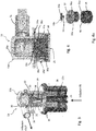
- Fig. 1 is a schematic illustration of one embodiment of an extracorporeal blood treatment system in which the improved technology described herein is implemented.
- the illustrated system has an extracorporeal blood treatment apparatus 1 (also referred to as "apparatus 1") having a housing 1a, a user interface 12, a (blood) pump 11 and a control unit 14 (labeled as CPU in Fig. 1 ). Further, the housing 1a holds a treatment unit 2, and components of an extracorporeal blood circuit 3 such as a blood return line 5, a blood withdrawal line 6 and an air trap 8 inserted in the blood return line 5 that feeds treated blood back to a patient.
- the user interface 12 may include a display screen and a keypad, a touch screen or a combination thereof.
- a fluid circuit for a dialysis fluid is not shown in Fig. 1 , but the illustration of the system in Fig. 2 shows such a dialysis fluid circuit.
- the system includes further a pre-/post-infusion valve unit 13 (hereinafter referred to as "valve unit 13") and an infusion pump 4, wherein the valve unit 13 is coupled to the infusion pump 4 and via pre-infusion line 10 and post-infusion line 7 to the extracorporeal blood circuit 3.
- the valve unit 13 is used when the patient's treatment requires pre-infusion or post-infusion or a combination of pre- and post-infusion.
- additional details regarding various optional embodiments of the extracorporeal blood circuit 3 and associated components, such as sensors and actuators, are described below.
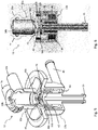
- Fig. 2 shows a simplified illustration of the system shown in Fig. 1 , wherein the valve unit 13 is mounted to the housing 1a of the apparatus 1, and coupled to the infusion pump 4 and the extracorporeal blood circuit 3.
- the housing 1a is represented by a cross-section of a housing wall (hatched area) to indicate components located inside the housing 1a (left side) and components located outside the housing 1a (right side).
- a fluid module 20 is located inside the apparatus 1 and includes the infusion pump 4, an ultra-filter 22 for removing particles and/or bacteria from the infusion liquid to obtain a pure infusion liquid, a fluid line 21 (also referred to as "bypass line") and access ports for lines 23, 24 of the dialysis fluid circuit.
- the infusion pump 4 is located inside the apparatus 1, and the ultra-filter 22 is connected between the valve unit 13 and the infusion pump 4.
- the fluid module 20 is generally configured to handle fluids other than blood and to perform a variety of functions, such as providing the infusion fluid to the external blood circuit 3 on the outside of the apparatus 1, and providing the dialysis fluid for supply to the treatment unit 2 on the outside.
- the fluid module 20 at least controls the flow of these fluids.
- the fluid module 20 may perform additional functions, such as preparing a fluid, e.g., the dialysis fluid, disposing of used dialysis fluid, priming the system and other functions known to the skilled person.
- fluid module is used herein in a non-limiting way. That is, although the fluid module 20 is shown to be inside the apparatus 1, in certain embodiments some functions may have components located on the outside of the apparatus 1, e.g., the lines 23, 24 connected to the treatment unit 2, or the infusion lines 7, 10 connected to the extracorporeal blood circuit 3. Those skilled in the art will appreciate that it is a matter of definition and design choice whether or not certain components, regardless of where they are located in a particular embodiment, are viewed as a part of the fluid module 20. For that reason, the fluid module 20 is shown in Fig. 2 by means of dashed lines.
- the infusion line 7 connects the valve unit 13 to the blood return line 5 to allow post-infusion
- the infusion line 10 connects the valve unit 13 to the blood withdrawal line 6 to allow pre-infusion.
- the infusion line 7 is in Fig. 2 connected to the blood return line 5 upstream of the air trap 8, it is contemplated that in another embodiment the infusion line 7 may be connected to the air trap 8. In both embodiments, the air trap 8 ensures that treated blood is essentially free of air bubbles before it is returned to the patient.
- a clamp 26, 27 is provided on each infusion line 7, 10 and configured to allow or interrupt fluid flow through the respective infusion line 7, 10.
- the clamps 26, 27 are manually operated. That is, depending on whether the patient's treatment includes pre- or post-infusion, or both, the operator opens or closes the clamps 26, 27.
- the clamps 26, 27 are configured to be actuated by the control unit 14. It is contemplated that the skilled person is familiar with the various kinds of clamps.
- the treatment unit 2 is connected to the dialysis fluid circuit.
- the line 23 of the dialysis fluid circuit feeds the dialysis fluid to the treatment unit 2, and the line 24 guides used dialysis fluid away from the treatment unit 2.
- the dialysis fluid and the blood flow in opposite directions.
- the valve unit 13 extends through the housing wall. As described in more detail with reference to the various embodiments shown in Figs. 3 - 6 , the valve unit 13 has a first part 13b and a second part 13a that is releasable connectable to the first part 13b.
- the first part 13b is mounted on the housing 1a, and has an inlet 25 coupled to the infusion pump 4.
- the first part 13b forms or is part of an infusion port.
- the second part 13a has a first outlet 7a coupled to the infusion line 7 and a second outlet 10a coupled to the infusion line 10.
- the infusion lines 7, 10 are part of an infusion circuit which is configured to couple to the extracorporeal blood circuit 3.
- the second part 13 includes a one-way valve configured to allow infusion liquid to flow from the inlet 25 towards at least one of the first and second outlets 7a, 10a, and to block fluid (back) flow towards the inlet 25.
- a one-way valve is also known as check valve, clack valve or non-return valve, and allows fluid (liquid or gas) to flow through it in only one direction.
- Various embodiments of a one-way valve are shown in Figs. 3 - 6 and described below.
- the one-way valve is a normally-closed valve, i.e., the valve is closed unless the pressure at which the infusion fluid is pumped in direction of the valve unit 13 exceeds a predetermined pressure.
- This predetermined pressure is sometimes referred to as "cracking pressure" which is the minimum upstream pressure at which the valve will operate.
- a one-way valve is designed and specified for a specific cracking pressure.
- the first part 13b is installed on the apparatus 1, and the second part 13a can be connected to the first part 13b, e.g., by the operator when setting-up the system for an extracorporeal blood treatment.
- the pressure caused be the infusion pump 4 when pumping the infusion liquid causes the one-way valve to open (i.e., the pressure exceeds the valve's cracking pressure) and the infusion fluid flows into at least one of the infusion lines 7, 10 depending on which clamp 26, 27 is open.
- the valve closes.
- the valve In its closed state, the valve prevents any fluid to flow or diffuse from an infusion line 7, 10 into the first part 13b of the valve unit 13. With that, the risk of backflow and/or cross-contamination is reduced. This is of particular importance in case a non-occlusive pump (e.g., a gear pump) is used as the infusion pump 4 instead of an occlusive pump (e.g., a peristaltic pump) as described below.
- a non-occlusive pump e.g., a gear pump
- an occlusive peristaltic pump inherently always pinches the tube and thereby prevents backflow.
- a gear pump does not have such inherent function and under certain pressure conditions fluid could flow back towards the gear pump.
- Fig. 2 further shows that the infusion lines 7, 10 connect via the second part 13a to the infusion port, but not directly.
- the first part 13b is thereby never in direct contact with the infusion lines 7, 10.
- the second part 13a which is in contact with the infusion lines 7, 10, may be configured to be releasable from the infusion lines 7, 10 to facilitate cleaning and/or sterilizing.
- the second part 13a may be a disposable part that is replaced after use.
- the second part 13a may be an integral part of the infusion lines 7, 10 forming a set for single or (after cleaning and/or sterilizing) multiple use.
- the infusion port is not used, it is covered by a cap (not shown in Fig. 2 ) that protects the infusion port from contamination or damage.
- the cap closes a bypass for fluid used to prime or disinfect the infusion port.
- the infusion pump 4 is located inside the apparatus 1 as shown in Fig 2 . It is contemplated, however, that the infusion pump 4 may be located at another location as well, e.g., on an outer area of the apparatus 1 or spaced from the apparatus 1. This applies to all embodiments of the valve unit 13 described herein.
- the infusion pump 4 may have one of several configurations; for example, it may be a peristaltic pump or a gear pump.
- a peristaltic pump fluid is contained within a flexible tube fitted inside a circular pump casing.
- a rotor with a number of “rollers” compresses the flexible tube, and, as the rotor turns, the part of the tube under compression is pinched closed (or "occludes”).
- the periodic pinching forces the fluid to be pumped to move through the tube.
- a gear pump has two external spur gears, or an external and an internal spur gear. As the gears rotate they separate on the intake side of the pump, creating a void and suction which is filled by fluid.
- the fluid is carried by the gears to the discharge side of the pump, where the meshing of the gears displaces the fluid.
- the above-mentioned problems of backflow and cross-contamination are usually less critical in a system that uses a peristaltic pump to infuse a liquid than in a system that uses a gear pump.
- the usually disposable tube prevents that the fluid gets into direct contact with the (non-disposable) pump or its parts.
- fluid is in direct contact with (non-disposable) parts of a gear pump.
- a gear pump may be preferred over a peristaltic pump and allow new system configurations because gear pumps, for example, no longer need to be accessible to allow insertion of a fluid tube.
- the infusion pump 4 is a gear pump. It is contemplated, however, that application of the improved technology described herein is not limited to a gear pump, and may be used in connection with a peristaltic pump as well.
- Fig. 3 is a schematic perspective view of one embodiment of the valve unit 13 having a first valve structure, with a section removed to show internal components of the valve unit 13. Due to the removal of the section only one outlet (7a) is shown, however, it is contemplated that the valve unit 13 has two outlets 7a, 10a, as shown in Fig. 2 . Further, for ease of illustration, the valve unit 13 is shown without being attached to the apparatus 1 or being connected to the infusion lines 7, 10, however, it is contemplated that the first part 13b of the valve unit 13 is mounted to the apparatus 1.
- the second part 13a is configured to have a male connecting part
- the first part 13b is configured to have a female connecting part.
- the female connecting part receives the male connecting part in a releasable and sealing manner.
- at least one of the male and female connecting parts has a seal.
- the second part 13a has a circumferential seal 28 at the part that interacts with the first part 13b.
- the seal 28 may be made of silicon or other suitable material. It is contemplated that other locking and sealing mechanisms such as a Luer lock, a screw connection, a bayonet coupling or other suitable locking mechanisms known to the skilled person may be used.
- the second part 13a is contoured to have an outer surface 32 that may be sized to allow manipulation by the operator, and that may be structured or textured to allow secure gripping by the operator.
- the outer surface 32 has circumferential ribs; however, any other suitable structures may be used.
- the contour of the valve unit 13 shown in Fig. 3 it is contemplated that the structure and dimension of the outer surface 32 can be selected to a meet certain space and/or handling requirements. This applies also to the embodiments shown in Figs. 4 - 6 .
- the particular contours shown in these figures are, therefore, exemplary and not to be viewed as limiting.
- the second part 13a has a generally cylindrical hollow body, in which a valve seat 34 and a sealing member 33 are positioned.
- the valve seat 34 and the sealing member 33 divide the internal space into an output chamber 30 and an input chamber 31.
- the output chamber 30 is in fluid communication with the outlets 7a, 10a, and the input chamber 31 is in fluid communication with the inlet 25 of the valve unit 13.
- the input chamber 31 and the output chamber 30 are cylindrical and coaxial (provided with the same main axis of the cylinder).
- the valve seat 34 has a platform that is attached to the body of the second part 13a.
- the valve seat 34 is a hollow cylinder that is open on a side that faces the first part 13b and that has the platform on the opposite side.
- the valve seat's platform has a central opening through which a stem 29 of the sealing member 33 extends from the output chamber 30 into the input chamber 31. The stem 29 thereby secures the sealing member 33 to the valve seat 34.
- the stem 29 has a radially extending, generally disc-shaped structure 29a.
- the disc-shaped structure is made of a flexible material that is biocompatible, e.g., silicon.
- the disc-shaped structure 29a may be referred to as a diaphragm.
- the sealing member 33 with such a stem 29 and disc-shaped structure 29a has a generally T-shaped cross-section.
- the disc-shaped structure 29a has a cross-section with a curved (e.g., convex) upper surface that faces the output chamber 30 and a flat or slightly curved (e.g., concave) lower surface that faces the valve seat 34.
- the sealing member 33 When viewed from a side, has a general shape that resembles an umbrella.
- the valve seat 34 (on the platform side) has at least one fluid channel to allow passage of the infusion liquid.
- the function of allowing passage of the infusion liquid may be achieved in a variety of ways.
- several fluid channels are arranged in a circle around the central opening.
- the disc-shaped structure 29a of the sealing member 33 is configured and sized to extend over the fluid channels. In a closed position of the valve unit 13, the structure 29a covers the fluid channels and prevents passage of the infusion fluid.
- the central opening and the fluid channels may be arranged as in the embodiment described with reference to Figs. 4 and 4a . However, it is contemplated that more or less fluid channels in various arrangements may be used in a particular embodiment.
- the sealing member 33 is positioned to create a normally-closed valve. Pressure on the upstream side must be greater than the pressure on the downstream side by a certain amount, known as the pressure differential, for the check valve to open allowing flow. Once positive pressure stops, such a diaphragm-like structure automatically flexes back to its original closed position.
- valve unit 13 of Fig. 3 is in the closed position when the pressure in the input chamber 31 is below the cracking pressure. If the pressure in the input chamber 31 exceeds the cracking pressure, the infusion fluid pressure urges the structure 29a towards the output chamber 30 uncovering the one or more fluid channels and opening the valve unit 13.
- this part is configured to allow its mounting to the housing 1a, to secure the second part 13a, which extends at least partially into the first part 13b, and to allow passage of the infusion fluid from the inlet 25 to the input chamber 31.
- the first part 13b has in one embodiment a cylindrical body that fits into a correspondingly sized opening in the wall of the housing 1a. When inserted into the opening, a rim with a larger diameter presses from the outside against the wall to secure the body in the housing 1a in combination with a counter screw or other retaining mechanism.
- the first part 13b has a channel 35 that extends between the inlet 25 and the input chamber 31.
- the first part 13b is configured to provide in combination with the second part 13a for a fluid tight seal, as described above.
- the channel 35 is coaxial with respect to the inlet 25 and to the input and output chambers 31, 30 while the first and the second outlets 7a, 10a are parallel to each other and orthogonal with respect to the common main axis of the input chamber 31, of the output chamber 30, of the channel 35 and of the inlet 25.
- Fig. 4 is a schematic cross-sectional view of another embodiment of a valve unit 13 having a second valve structure, and Fig. 4a shows components of the second valve structure.
- Fig. 3 only one outlet (7a) is shown, although the valve unit 13 has two outlets 7a, 10a, as shown in Fig. 2 .
- the valve unit 13 is again shown without being attached to the apparatus 1 or connected to the infusion lines 7, 10, however, it is contemplated that the first part 13b of the valve unit 13 is mounted to the apparatus 1.
- the (female) first part 13b and the (male) second part 13a interact in a releasable and sealing manner, and may have complementary locking mechanism as described above with reference to Fig. 3 .
- the valve unit 13 has a valve seat 34a that is attached to the second part 13a.
- the valve seat 34a has a platform that is attached to the body of the second part 13a.
- the valve seat 34a includes further a hollow cylinder that extends from the platform towards the first part 13b and is open on that side (i.e., opposite the platform). On the open side, the cylinder has a flange.
- the valve seat 34a has a sealing member 33a that is mounted by means of a stem 39 to a central opening 37 of the valve seat 34a.
- the valve seat 34a has fluid channels 36a, which extend between the output chamber 30a and the input chamber 31a, and are, for example, arranged in a circle around the central opening 37. In the illustrated embodiment, the central opening 37 and the fluid channels 36a are implemented in the valve seat's platform.
- the sealing member 33a has a generally T-shaped cross-section and a flexible disc-shaped structure 39a that is sized to cover the fluid channels 36a in a normally-closed state.
- the structure 39a has a cross-section with a curved (e.g., convex) upper surface that faces the output chamber 30a and a flat or curved (e.g., concave) lower surface that faces the valve seat 34a.
- the sealing member 33a When viewed from a side, the sealing member 33a has a general shape that resembles an umbrella.
- the stem 39 of the sealing member 33a shown in Fig. 4 is shorter than the stem 29 of the sealing member 33 shown in Fig. 3 .
- the valve unit 13 can therefore be built smaller. Further, the volume of the input chamber 31a is lower than the volume of the input chamber 31 of Fig. 3 .
- the first part 13b includes a seal 38 made of an elastic material, e.g., silicon.
- the seal 38 has an annular groove 46 sized to receive the valve seat's cylinder part with its flange. The elasticity of the material provides for proper sealing and for a snug fit between the seal 38 and the valve seat 34a, as is visible in Fig. 4 .
- the seal 38 has further a through hole that is aligned with the central opening 37 and the fluid passages 36a of the valve seat 34a. In use, infusion fluid flows from the inlet 25 through the through hole and the fluid channels 36a.
- the seal 38 constitutes the first part 13b. That is, it is the part that is mounted to the housing 1a, e.g., by inserting the seal 38 directly inserted into an opening in the housing 1a.
- the seal 38 may be inserted into a casing so that the seal 38 and the casing constitute the first part 13b.
- the through hole of the seal 38 corresponds to the input chamber 31a.
- the output chamber 30a is larger than the input chamber 31a.
- Fig. 5 is a schematic perspective view of one embodiment of a valve unit 13 having a third valve structure and a bypass port 45; and Fig. 6 is a schematic cross-sectional view of the valve unit 13 of Fig. 5 .
- the bypass port 45 is optional, and Fig. 6 does not show a bypass port. It is contemplated that the embodiments shown in Figs. 3 and 4 may have a bypass port as well.
- Fig. 7 shows the embodiment of Fig. 5 with the second part 13a removed and the first part 13b being covered by a cap 47.
- the cap 47 not only protects the infusion port from damage and/or contamination, it also closes a bypass for fluid used during disinfecting and rinsing the apparatus 1.
- the third valve structure is based on a sealing mechanism that is different from those sealing mechanisms described with reference to Figs. 3 and 4 . That is, the sealing mechanism is based on a membrane principle.
- a membrane 40 e.g., disc-shaped, is positioned in a circular membrane chamber 41 of a valve seat 34b.
- the valve seat 34b is attached to the second part 13a which is inserted into the (female) first part 13b.
- a ring seal 42 is attached to an end section of the second part 13 that is inserted into the first part 13b.
- a cavity 43 remains between the ring seal 42 and a bottom of the first part 13b.
- the bypass port 45 is mounted to be in fluid communication with the cavity 43. When the infusion port is not in use and, hence, is covered by a cap, fluid can flow from the inlet 25 towards the cap and the cavity 43, and then into the bypass port 45.
- the valve seat 34b has a fluid channel 36b that extends between a side facing the output chamber 30b and a side facing the input chamber 31b. Within the valve seat 34b, the membrane chamber 41 is inserted into the fluid channel 36b. Depending on the position of the membrane 40, fluid flow through the fluid channel 36b and the membrane chamber 41 is either enabled or blocked.
- the membrane chamber 41 has an inner shape that allows the membrane 40 to move back and forth (in Fig. 5 , up and down) within the membrane chamber 41.
- the inner shape is conical with a larger diameter at the side that faces the output chamber 30b (this side is in Fig. 5 an upper side) and a smaller diameter at the side that faces the input chamber 31b (this side is in Fig. 5 a lower side) .
- the membrane 40 moves either towards the (larger diameter) upper side that faces the output chamber 30b, i.e., the valve opens, or towards the (smaller diameter) lower side that faces the input chamber 31b, i.e., the valve closes.
- ribs, protrusions or other suitable structures on the upper side prevent that the membrane 40 covers the fluid channel 36b and interrupts flow of the infusion fluid.
- the output chamber 30a is much larger than the input chamber 31a. Furthermore, as shown in figure 6 , the main axes of each of the first and the second outlets 7a, 10a are substantially tangential with respect to a cylindrical inner surface of the output chamber 30b.
- the control unit 14 is configured or programmed to operate the apparatus 1 during all stages of a treatment.
- the control unit 14 has a (central) processing unit (CPU) coupled to or containing a data storage for storing computer-readable instructions/programs or data.
- the data storage may comprise a mass storage device based on one of a variety of technologies, for example, optical or magnetic, a re-programmable memory (EPROM, FLASH) or other known storage media.
- the control unit 14 is coupled to the user interface 12 and other components of the apparatus 1 by means of a communications bus or control lines, or a combination thereof.
- the control unit 14 communicates with the user interface 12 to enable entry of patient-specific data (personal and prescription data (e.g., kind of therapy (HD, HDF, HF), dialysis target values, dialysis duration).
- patient-specific data personal and prescription data (e.g., kind of therapy (HD, HDF, HF), dialysis target values, dialysis duration).
- the control unit 14 activates a communications device to read data from a patient card.
- control unit 14 controls operation of the pump 11, sensors and actuators according to the prescribed therapy (e.g., HD, HDF, HF, with or without pre-/post infusion), processes control parameters (e.g., sensor readings, actuator settings), and displays one or more of the processing results, sensor readings and actuator settings on a screen of the user interface 12.
- prescribed therapy e.g., HD, HDF, HF, with or without pre-/post infusion
- processes control parameters e.g., sensor readings, actuator settings
- the treatment unit 2 has a primary chamber 15 and a secondary chamber 16 separated by a semipermeable membrane 17.
- the membrane 17 may be selected to have different properties and performances.
- the treatment unit 2 may be configured as a hemofilter, a hemodiafilter, a plasma filter, or a dialysis filter.
- a blood withdrawal line 6 of the extracorporeal blood circuit 3 is connected to an inlet of the primary chamber 15, and a blood return line 5 of the extracorporeal blood circuit 3 is connected to an outlet of the primary chamber 15.
- the treatment unit 2 is replaceable mounted by a holder 18 to a front panel or a side panel of the housing 1a of the apparatus 1.
- the extracorporeal blood circuit 3 is replaceable mounted by a holder 19 to a front panel or a side panel of the housing 1a.
- the blood withdrawal line 6 and the blood return line 5 are connected to a needle or to a catheter or other access device (not shown) which is then placed in fluid communication with the patient's vascular system, such that blood can be withdrawn through the blood withdrawal line 6, passed through the primary chamber 15 and then returned to the patient's vascular system through the blood return line 5.
- An air separator such as the bubble trap 8 is inserted into the blood return line 5.
- a safety clamp 9 controlled by the control unit 14 may be present on the blood return line 5 downstream the bubble trap 8.
- a bubble sensor for instance associated with the bubble trap 8 or coupled to a portion of the line 5 between the bubble trap 8 and the clamp 9 may be present. If present, the bubble sensor is coupled to the control unit 14 to enable the control unit 14 to cause closure of the clamp 9 in case a critical number of bubbles is detected, e.g., one or more bubbles above a safety threshold.
- the withdrawal line 6 and return line 5 may include any one of the arterial and venous lines of known type used in an apparatus for hemodialysis or hemo(dia)filtration.
- the withdrawal line 6 and return line 5 may be equipped with and/or connected to various sensors and actuators of known type (for example, pressure sensors, blood presence sensors or patient presence sensors, liquid level sensors, air presence sensors, blood transport pumps, infusion liquid transport pumps, automatic block valves, liquid level regulation devices, etc.) for the control and monitoring of the circuit itself, and to various devices of known type (gas-liquid separation devices, removal-injection access sites, manual clamps, service lines, etc.) for performing various operations on the circuit.
- sensors and actuators for example, pressure sensors, blood presence sensors or patient presence sensors, liquid level sensors, air presence sensors, blood transport pumps, infusion liquid transport pumps, automatic block valves, liquid level regulation devices, etc.
- various devices of known type gas-liquid separation devices, removal-injection access sites, manual clamps, service lines, etc.
- a sensor may be arranged in the extracorporeal blood circuit 3 (e.g., located in the blood withdrawal line 6) to emit a signal that is indicative of a change of blood volume of the patient.
- a sensor may include, for example, an optical or acoustic sensor.
- the blood volume sensor indicates blood volume changes.
- the user may enter a predetermined value for the blood flow rate using the user interface 12, and the control unit 14 controls during the treatment the pump 11 based on the predetermined blood flow rate.
- the extracorporeal treatment apparatus may further have a system for supplying a fresh treatment fluid in a predetermined composition.
- the supply system may comprise any of the supply systems of known type used to supply a dialysis and/or replacement fluid in a hemodialysis or hemo(dia)filtration apparatus (for example of the type with in-line preparation of the treatment fluid from water and concentrates of the type sourcing from a batch-type source such as one or more bags of fluid).
- the supply system may have a supply line connected to an inlet of a fluid chamber, a source of treatment fluid (batch-type or in-line preparation type) and a supply pump.
- the sensor is in this case connected to the supply line to take into account, when determining the individual's weight loss, the flow of the treatment fluid, in particular dialysis fluid entering the fluid chamber and/or possibly replacement fluid infused into the extracorporeal circuit 3.
- the source has a device for in-line preparation of a treatment fluid having a predetermined concentration.
- the preparation device may comprise any of the devices of known type used in a hemodialysis or hemo(dia)filtration machine.
- the preparation device may prepare the treatment fluid starting from water and concentrates by using of one or more sensors, for example, an electrical conductivity sensor (or another type of sensor for determining the composition of the dialysis solution) in order to determine, in a known way, the composition of the prepared fluid.
- an electrical conductivity sensor or another type of sensor for determining the composition of the dialysis solution
- the extracorporeal blood circuit 3 with the withdrawal and return lines 6, 5 and the air trap 8, the infusion circuit comprising the pre and post infusion lines 10, 7 and the second part of 13a the infusion valve unit 13 form part of a disposable set which is replaced after use.
- the air trap 8 comprises a box 44 delimiting a chamber and closed by a cap 45.
- a bottom wall 46 of the box 44 is provided with an inlet 5a for a part of the return line 5 coming from the treatment unit 2.
- the bottom wall 46 is also provided with an outlet 5b for a part of the return line 5 going back to the vascular system of the patient P.
- the cap 45 closes an upper opening of the box 44.
- a partition wall 47 protrudes partially inside the chamber towards the cap 45 and separates the inlet 5a from the outlet 5b.
- a filter 48 is placed at the outlet 5b.
- the cap 45 supports a section 47 of the blood withdrawal line 6.
- the blood withdrawal line 5 coming from the arterial vascular access enters the cap 45, passes through the cap 45 (by means of the section 47) and exits the cap 45 to reach the treatment unit 2.
- the section 47 and the blood withdrawal line 6 are not in fluid communication with the chamber of the box 44.
- the pre-infusion line 10 presents a first end connected to the second outlet 10a of the second part 13a of the valve unit 13 and a second opposite end connected to the section 47 of the blood withdrawal line 6 at a T joint 48 made into the cap 45.
- the second end of the pre-infusion line 10 is joined to the cap 45.
- the post-infusion line 7 presents a first end connected to the first outlet 7a of the second part 13a of the valve unit 13 and a second opposite end connected to the air trap 8.
- the cap 45 supports a section 49 of the post-infusion line 7 close to the second opposite end.
- the second end of the post-infusion line 7 opens into the box 44 passing through the cap 45, by means of said section 49 of the post-infusion line 7.
- the cap 45 is shaped such as to define the section 47 of the blood withdrawal line 6, the T joint 48 and the section 49 of the post infusion line 7.
- the cap 45 is made of rigid plastic material. The stiffness of the material of the cap 45 is such to support the lines without deforming said cap 45.
- the disposable set is pre-assembled in the sense that all its elements (blood withdrawal line 6, cap 45, blood return line 5, pre-infusion line 10, post-infusion line 7, second part 13a of the valve unit 13) are joined each other during manufacturing and stored and sold as an assembly in a single packaging.
- the disposable set is mounted to the housing 1a of the apparatus 1.
- the treatment unit 2 is mounted to the housing 1a too.
- the extracorporeal blood circuit 3 is coupled to the treatment unit 2 and to the blood pump 11.
- the second part 13a of the infusion valve unit 13 is coupled to the first part 13b of the infusion valve unit 13.
- said disposable set comprises the extracorporeal blood circuit 3 with the withdrawal and return lines 6, 5 and the air trap 8, the infusion circuit comprising the pre and post infusion lines 10, 7 and all the infusion valve unit 13.
- the first part 13b and the second part 13a of the infusion valve unit 13 can be a single body or can be firmly connected (not releasably connected). All the infusion valve unit 13 is part of the disposable set.
- the outlet 25 of said valve unit 13 comprises or is connected (by example through a section of pipe) to a connector which is releasably connectable to a connector mounted on the housing 1a of the blood treatment system.
- the connector on the housing can be firmly mounted on said housing or can be joined to a section of pipe coming from said housing.
- the hemodiafiltration apparatus operates in one embodiment in a known way to affect a predetermined weight loss in the patient, giving rise to an ultrafiltration device for ultrafiltering liquid from the blood chamber 15 to the fluid chamber 16 through the semipermeable membrane 17.
- the ultrafiltration is carried out by exploiting the pressure difference at the two sides of the membrane 17 (transmembrane pressure, or TMP) and the resulting convective transport of liquid generated by a discharge pump which enables having a pressure in the chamber fluid that is lower than the pressure in the blood chamber.
- TMP transmembrane pressure
- the ultrafiltration means are of known.
- the user interface 12 allows input of data, such as patient information, desired weight loss or desired weight loss rate, treatment time, significant parameters of the treatment and/or of the individual, etc.
- the user interface also displays and/or visually outputs data, such as patient information, treatment information and/or significant parameters of the treatment and/or of the individual, acoustic and/or visual alarms, etc.
Description
- The technology described herein relates generally to treating blood outside (i.e., extracorporeal) of a patient's body. More specifically, the technology relates to an extracorporeal blood treatment system with a valve unit for pre- and/or post-infusion of a predetermined fluid to the patient's blood.
- An extracorporeal blood treatment involves removing blood from a patient, treating the blood outside the patient's body, and returning the treated blood to the patient. Extracorporeal blood treatment may be used to extract undesirable substances or molecules from the patient's blood, and, if necessary, to add desirable substances or molecules to the blood. An extracorporeal treatment of blood may be required, for example, when a patient's kidneys are unable - whether temporarily or permanently - to effectively remove substances from the blood. The patient is then required to undergo extracorporeal blood treatment to add or remove substances to the blood, to maintain a certain acid/base balance or to remove excess body fluids, for example.
- This is typically accomplished by passing blood through a treatment unit, e.g., a dialyzer or a hemofilter. Blood is removed from the patient in, e.g., a continuous flow, and introduced into a primary chamber, also referred to as blood chamber, of the treatment unit. Therein, the blood flows past a semipermeable membrane that selectively allows matter in the blood to cross the membrane from the primary chamber into a secondary chamber and also selectively allows matter in the secondary chamber to cross the membrane into the blood in the primary chamber, depending on the type of treatment. The secondary chamber is also referred to as fluid chamber.
- A number of different types of extracorporeal blood treatments may be performed. In an ultrafiltration (UF) treatment, undesirable matter is removed from the blood by convection across a membrane into the secondary chamber. In a hemofiltration (HF) treatment, the blood flows past the semipermeable membrane as in a UF treatment and desirable matter is added to the blood, typically by dispensing a fluid into the blood either before and/or after it passes through the treatment unit and before it is returned to the patient. In a hemodialysis (HD) treatment, a secondary fluid containing desirable matter is introduced into the secondary chamber of the treatment unit. Undesirable matter from the blood crosses the semipermeable membrane into the secondary fluid and desirable matter from the secondary fluid may cross the membrane into the blood. In a hemodiafiltration (HDF) treatment, blood and secondary fluid exchange matter as in HD, and, in addition, matter is added to the blood, typically by dispensing a fluid into the treated blood before its return to the patient as in HF.
- As mentioned, in some of these treatments, fluid and with it predetermined matter can be added to the patient's blood. In these cases, if some of the removed fluid needs to be replaced, a correctly balanced electrolyte/buffer dialysis solution (also named infusion fluid or replacement fluid) is infused into the extracorporeal blood circuit. With reference to the blood flow, this infusion may be done either before the dialyzer (pre-infusion) or after the dialyzer (post-infusion), or both. Pre-infusion and post-infusion are also referred to as pre-dilution and post-dilution, respectively, as any infusion of liquid leads to a dilution of the blood.
-
EP 1424089 discloses a dialysis machine having an infusion main tube that forks into a pre-dilution tube and a post-dilution tube, wherein the main tube is coupled to an infusion pump. A valve set is arranged downstream from the fork to act upon the pre- and post-dilution tubes. The valve set includes a pinch valve and an electromagnet for operating the valve. A control unit operates the pinch valve to control the flow of the infusion liquid in the pre- and post-dilution tubes. - Although
EP 1424089 focuses on controlling the infusion flow using the valve set, in systems for extracorporeal blood treatment other aspects need to be addressed as well to ensure a safe and reliable treatment of the patients. These aspects concern, for example, the ease of handling disposables such as circuits for blood and dialysis fluid to reduce the time for setting up the system and the risk of misconnections. Another aspect concerns the risk of cross-contaminating non-disposable components of the system with fluids (e.g., blood) from a patient. - Document
US2013028788 discloses an extracorporeal blood circuit having a withdrawal and a return line for the blood and extending on the exterior and in the interior of a blood cassette and connecting it with a treatment apparatus. An arterial section of the extracorporeal blood circuit is inserted into a blood pump. The extracorporeal blood circuit comprises an addition point for substituate liquid (in pre-dilution) and an addition point for substituate liquid (in post-dilution). DocumentUS2013028788 fig. 1 further shows a substituate pump located downstream of a connection point at which the blood cassette may be connected with its substituate port with an automatic substituate connector of the treatment apparatus. The automatic substituate connector comprises a first fluid conduct, a second fluid conduct and a third fluid conduct for rinsing the automatic substituate connector and for conducting substituate through the automatic substituate connector. A blood filter with a blood chamber and a dialysate chamber is integrated into the extracorporeal blood circuit. The blood cassette comprises a venous air separation chamber. A substituate line of the blood cassette comprises a non-return valve. -
WO2010/121819 discloses an external functional device comprising at least one housing element, chambers that are integrated into the housing element and hold medical fluids, ducts that are integrated into the housing element and hold and conduct a medical fluid, and valve mechanism that is integrated into the housing element and controls a fluid flowing through the external functional device. - Document
WO9515194 - Document
US2006089605 shows needleless connector for adding medication to a parenteral fluid comprising a connector to receive a syringe and having a check valve to seal the port in place of a puncture pad. The check valve comprises a resilient disc held in place and biased - closed by the tensile stress of the check valve material. When a syringe is engaged with the connector and fluid pressure is applied to the check valve, the resilient disc is deformed which allows the medication to flow through the connector into the tubing and thus to the patient.
- Document
WO2008146144 discloses an extracorporeal blood treatment kit having an intake branch designed to be connected to the hematic circuit of a patient, an activation assembly designed to co-operate with a device for generating pulsating pressure for controlling a flow of the fluid in the intake branch, a delivery- branch downstream of the intake branch and of the activation assembly and a connection outlet element connected to the delivery branch and to the hematic circuit of the patient. In particular, the kit comprises a first non-return valve and a second non-return valve set in line, respectively, on the intake branch and on the delivery branch. - Document
EP0189561 shows a hemodiafiltration apparatus with a closed dialysis solution cycle, which has a balancing system. Into the closed cycle, a first sterile filter is connected from which a connecting line leads to the venous drip chamber of the blood path. Connected into said connecting line downstream of the first sterile filter is a substituate pump, which is followed downstream by a second sterile filter. - Document
WO2009074588 describes a unit for the infusion of a substitute solution by a dialysis machine comprising a flushing device internally defining a flushing chamber and comprising a connecting cone extending inside the flushing chamber and suited to be hydraulically connected to a substitute solution line inside a dialysis machine; a connecting device suited to connect connecting cone to a duct for infusing the substitute solution to a patient; and a shutter element suited to close the flushing device to isolate the flushing chamber if the connecting unit is in a flushing conformation. The connecting device comprises a tubular element having a first joining end suited to be connected to connecting cone of said flushing device and a second joining end suited to be connected to an infusion duct; and a blocking ring nut housed with freedom of rotation around the tubular element to which it is axially restrained and suited to engage and block flushing device if the connecting unit is in a dialysis conformation. - Document
US4919167 shows a check valve for providing mono-directional flow in medical devices. The check valve includes a valve means comprised of a valve member and a seat member disposed within a cylindrical channel. The valve member is coaxially aligned within the channel downstream of the seat member and provides a valve cavity into which a portion of the seat member is disposed. The interface between the valve member and the seat member creates a seal length. The valve member is radially stressed by the axial position of the seat member so that the sealing force along the seal length is substantially radial. Fluid flow passes through an axial bore in the valve seat member and upon sufficient pressure unseats the seal length and passes through the annular passageway between the valve member and the seat member. - There is, therefore, a need for an improved technology for an extracorporeal blood treatment system, in particular with respect setting up the system and protecting the system from cross-contamination. The invention is defined by the features of independent claim 1.
- The claimed invention involves a disposable set for an extracorporeal blood treatment system. The extracorporeal blood treatment apparatus comprises a housing. The disposable set comprises an extracorporeal blood circuit comprising a blood withdrawal line and a blood return line configured to be coupled to a blood treatment device. The disposable set comprises an infusion circuit comprising infusion lines coupled to the extracorporeal blood circuit. The infusion lines comprise a pre-infusion line and a post-infusion line. The disposable set comprises an infusion valve unit having a first part and a second part. Said second part comprises a first outlet coupled to the post-infusion line and a second outlet coupled to the pre-infusion line. Said second part comprises a one-way valve configured to allow infusion liquid to flow from an inlet towards at least one of the first and second outlets and to block fluid flow towards the inlet when the second part is releasably connected to the first part of the infusion valve unit. Said second part is configured to be releasably connectable to the first part of the infusion valve unit, the first part being mounted on the housing of the extracorporeal blood treatment apparatus and having the inlet which is coupled to an infusion pump of the extracorporeal blood treatment system. The pre-infusion line connects the infusion valve unit to the blood withdrawal line of the extracorporeal blood circuit and the post-infusion line connects the infusion valve unit to the blood return line of the extracorporeal blood circuit. The first and second parts of the infusion valve unit delimit, when releasably connected, an input chamber provided with the inlet and an output chamber provided with the first and second outlets. The input chamber and the output chamber are separated by a sealing mechanism. The first and second parts of the infusion valve unit are made of rigid (i.e. plastic) material, the stiffness of the material being such to support the infusion lines without deforming said infusion valve unit. The first and second outlets are each defined by tubular portions of said material developing from an outer surface of the second part of the infusion valve unit. The inlet is defined by a tubular portion developing from the first part of said valve unit.
- The improved technology provides for improved reliability and handling of the extracorporeal blood treatment system because only one infusion port for both pre- and post-infusion is present to which an operator needs to connect the infusion line set. When setting up the system for a treatment with pre- and/or post infusion, the operator removes in one embodiment a cap from the valve unit's first part and connects the second part to it. As only one component needs to be connected, the set-up time and the risk for misconnections are reduced.
- The improved disposable of the invention provides for easy handling and improved safety and reliability too, because the operation of setting up the system for a treatment is greatly simplified. The operator needs only to unpackage the disposable and to connect the blood lines to the treatment unit and the second part of the infusion valve unit to the first part of said valve unit already mounted on the housing or to connect the valve unit to the connector on the housing.
- As to the term "infusion port", it is contemplated that it is a matter of definition what is considered to be the infusion port. That is, the valve unit's first part alone may be considered to be the system's infusion port. Alternatively, the valve unit as a whole (i.e., with both parts) may be considered to be the system's infusion port.
- Advantageously, the handling is further improved because the valve unit integrates several functions into one unit: it is or forms an infusion port, it allows fluid to pass only in one direction, and implements a T-connector. For example, the operator does not have to handle a further T-connector to couple infusion fluid into the extracorporeal blood circuit.
- Additionally, as the one-way valve is positioned in the second part, which in use is connected to an infusion line, reduces or even eliminates the problem of dripping when undressing the system after its use. It is a further advantage that the valve unit is a passive component so that no additional control mechanism is required; opening and closing of the valve is caused by pressure drops.
- Further, the integrated one-way valve ensures that any fluid that may have been in contact with the patient or the patient's blood cannot enter the first part of the valve unit, and, hence, non-disposable parts of the system. As is known in the art, disposables are, e.g., those components of the system that are in contact with the patient's blood (e.g., the extracorporeal blood circuit, or the treatment unit) during a treatment session, and that are usually replaced thereafter.
- The improved technology provides flexibility regarding selecting a particular valve mechanism. One exemplary valve mechanism is based on a combination of a valve seat with at least one fluid channel, and a sealing member having a stem and a disc-shaped structure radially extending from one end of the stem. The disc-shaped structure is configured to extend beyond the fluid channel to cover it in a closed state.
- Another exemplary valve mechanism is based on a combination of a valve seat with at least one fluid channel, and a membrane arranged in a membrane chamber. Within the membrane chamber, the membrane is movable to either prevent fluid to flow through the fluid channel, or to allow such fluid flow. Such a membrane has a low forward flow pressure, and closing of the valve occurs with a very low pressure difference.
- In one embodiment, the infusion pump is located inside the system housing and connected to the valve unit's first part. As the infusion pump is located internally, space is freed up on the outside of the housing so that, e.g., cleaning is facilitated.
- Further, locating the infusion pump inside the housing allows use of a non-occlusive pump, e.g., a gear pump that uses rotating gears to transport a fluid. Inserting a tube of the extracorporeal blood circuit through a peristaltic pump is no longer required, which again reduces the time for setting-up the system. In addition, a gear pump generates less noise than a peristaltic pump so that the patient is no longer exposed to the periodic sound caused by the rollers of a peristaltic pump.
- It is a further advantage of the improved technology that the valve unit allows using a non-occlusive pump. A peristaltic pump inherently prevents backflow of fluid, but a gear pump does not have such an inherent characteristic. To protect the system from such backflow, the valve unit includes a one-way valve for which various configurations are possible.
- In one embodiment, the valve unit has a bypass port at the first part, wherein the bypass port is coupled to a bypass line. When the second part is not connected, a cap is placed on top of the first part. With the cap placed, the first part is not only protected against damage and/or contamination, but also sealed. The cap therefore closes a bypass for fluid that may be used, e.g., during disinfection and/or rinsing of the system.
- The novel features characteristic of the invention are set out in the claims below. The invention itself, however, as well as other features and advantages thereof, are best understood by reference to the detailed description, which follows, when read in conjunction with the accompanying drawings, wherein:
- Fig. 1
- shows a schematic illustration of one embodiment of an extracorporeal blood treatment system having a pre-/post-infusion valve unit;
- Fig. 2
- is a simplified illustration of the system shown in
Fig. 1 with the valve unit mounted to a housing of the system and coupled to an internal infusion pump; - Fig. 3
- is a schematic perspective view of one embodiment of a valve unit having a first valve structure;
- Fig. 4
- is a schematic cross-sectional view of one embodiment of a valve unit having a second valve structure;
- Fig. 4a
- is a schematic perspective view of components of the second valve structure;
- Fig. 5
- is a schematic perspective view of one embodiment of a valve unit having a third valve structure and a bypass line;
- Fig. 6
- is a schematic cross-sectional view of one embodiment of a valve unit having the third valve structure; and
- Fig. 7
- is a schematic cross-sectional view of one embodiment of a valve unit having the third valve structure with a cap;
- Fig. 8
- is an embodiment of a disposable set of the system of
figures 1 and2 . -
Fig. 1 is a schematic illustration of one embodiment of an extracorporeal blood treatment system in which the improved technology described herein is implemented. The illustrated system has an extracorporeal blood treatment apparatus 1 (also referred to as "apparatus 1") having ahousing 1a, auser interface 12, a (blood) pump 11 and a control unit 14 (labeled as CPU inFig. 1 ). Further, thehousing 1a holds atreatment unit 2, and components of anextracorporeal blood circuit 3 such as ablood return line 5, ablood withdrawal line 6 and anair trap 8 inserted in theblood return line 5 that feeds treated blood back to a patient. Theuser interface 12 may include a display screen and a keypad, a touch screen or a combination thereof. For ease of illustration, a fluid circuit for a dialysis fluid is not shown inFig. 1 , but the illustration of the system inFig. 2 shows such a dialysis fluid circuit. - In the embodiment of
Fig. 1 , the system includes further a pre-/post-infusion valve unit 13 (hereinafter referred to as "valve unit 13") and aninfusion pump 4, wherein thevalve unit 13 is coupled to theinfusion pump 4 and viapre-infusion line 10 andpost-infusion line 7 to theextracorporeal blood circuit 3. Thevalve unit 13 is used when the patient's treatment requires pre-infusion or post-infusion or a combination of pre- and post-infusion. For the sake of completeness, additional details regarding various optional embodiments of theextracorporeal blood circuit 3 and associated components, such as sensors and actuators, are described below. -
Fig. 2 shows a simplified illustration of the system shown inFig. 1 , wherein thevalve unit 13 is mounted to thehousing 1a of the apparatus 1, and coupled to theinfusion pump 4 and theextracorporeal blood circuit 3. Thehousing 1a is represented by a cross-section of a housing wall (hatched area) to indicate components located inside thehousing 1a (left side) and components located outside thehousing 1a (right side). - A
fluid module 20 is located inside the apparatus 1 and includes theinfusion pump 4, an ultra-filter 22 for removing particles and/or bacteria from the infusion liquid to obtain a pure infusion liquid, a fluid line 21 (also referred to as "bypass line") and access ports forlines infusion pump 4 is located inside the apparatus 1, and the ultra-filter 22 is connected between thevalve unit 13 and theinfusion pump 4. Thefluid module 20 is generally configured to handle fluids other than blood and to perform a variety of functions, such as providing the infusion fluid to theexternal blood circuit 3 on the outside of the apparatus 1, and providing the dialysis fluid for supply to thetreatment unit 2 on the outside. For these purposes, thefluid module 20 at least controls the flow of these fluids. Depending on a particular embodiment of the apparatus 1, thefluid module 20 may perform additional functions, such as preparing a fluid, e.g., the dialysis fluid, disposing of used dialysis fluid, priming the system and other functions known to the skilled person. - The term "fluid module" is used herein in a non-limiting way. That is, although the
fluid module 20 is shown to be inside the apparatus 1, in certain embodiments some functions may have components located on the outside of the apparatus 1, e.g., thelines treatment unit 2, or theinfusion lines extracorporeal blood circuit 3. Those skilled in the art will appreciate that it is a matter of definition and design choice whether or not certain components, regardless of where they are located in a particular embodiment, are viewed as a part of thefluid module 20. For that reason, thefluid module 20 is shown inFig. 2 by means of dashed lines. - On the outside of the apparatus 1, the
infusion line 7 connects thevalve unit 13 to theblood return line 5 to allow post-infusion, and theinfusion line 10 connects thevalve unit 13 to theblood withdrawal line 6 to allow pre-infusion. Although theinfusion line 7 is inFig. 2 connected to theblood return line 5 upstream of theair trap 8, it is contemplated that in another embodiment theinfusion line 7 may be connected to theair trap 8. In both embodiments, theair trap 8 ensures that treated blood is essentially free of air bubbles before it is returned to the patient. - A
clamp infusion line respective infusion line clamps clamps clamps control unit 14. It is contemplated that the skilled person is familiar with the various kinds of clamps. - Also on the outside of the apparatus 1, the
treatment unit 2 is connected to the dialysis fluid circuit. Theline 23 of the dialysis fluid circuit feeds the dialysis fluid to thetreatment unit 2, and theline 24 guides used dialysis fluid away from thetreatment unit 2. As is known in the art, in thetreatment unit 2 the dialysis fluid and the blood flow in opposite directions. - As shown in
Fig. 2 , thevalve unit 13 extends through the housing wall. As described in more detail with reference to the various embodiments shown inFigs. 3 - 6 , thevalve unit 13 has afirst part 13b and asecond part 13a that is releasable connectable to thefirst part 13b. Thefirst part 13b is mounted on thehousing 1a, and has aninlet 25 coupled to theinfusion pump 4. Thefirst part 13b forms or is part of an infusion port. Thesecond part 13a has afirst outlet 7a coupled to theinfusion line 7 and asecond outlet 10a coupled to theinfusion line 10. The infusion lines 7, 10 are part of an infusion circuit which is configured to couple to theextracorporeal blood circuit 3. - The
second part 13 includes a one-way valve configured to allow infusion liquid to flow from theinlet 25 towards at least one of the first andsecond outlets inlet 25. A one-way valve is also known as check valve, clack valve or non-return valve, and allows fluid (liquid or gas) to flow through it in only one direction. Various embodiments of a one-way valve are shown inFigs. 3 - 6 and described below. - In the embodiments shown in
Figs. 3 and 4 , the one-way valve is a normally-closed valve, i.e., the valve is closed unless the pressure at which the infusion fluid is pumped in direction of thevalve unit 13 exceeds a predetermined pressure. This predetermined pressure is sometimes referred to as "cracking pressure" which is the minimum upstream pressure at which the valve will operate. Typically, a one-way valve is designed and specified for a specific cracking pressure. - As mentioned above, the
first part 13b is installed on the apparatus 1, and thesecond part 13a can be connected to thefirst part 13b, e.g., by the operator when setting-up the system for an extracorporeal blood treatment. In use, the pressure caused be theinfusion pump 4 when pumping the infusion liquid causes the one-way valve to open (i.e., the pressure exceeds the valve's cracking pressure) and the infusion fluid flows into at least one of theinfusion lines infusion pump 4 is stopped, the valve closes. - In its closed state, the valve prevents any fluid to flow or diffuse from an
infusion line first part 13b of thevalve unit 13. With that, the risk of backflow and/or cross-contamination is reduced. This is of particular importance in case a non-occlusive pump (e.g., a gear pump) is used as theinfusion pump 4 instead of an occlusive pump (e.g., a peristaltic pump) as described below. An occlusive peristaltic pump inherently always pinches the tube and thereby prevents backflow. In contrast, a gear pump does not have such inherent function and under certain pressure conditions fluid could flow back towards the gear pump. -
Fig. 2 further shows that theinfusion lines second part 13a to the infusion port, but not directly. Thefirst part 13b is thereby never in direct contact with theinfusion lines second part 13a, which is in contact with theinfusion lines infusion lines second part 13a may be a disposable part that is replaced after use. In another embodiment, thesecond part 13a may be an integral part of theinfusion lines Fig. 2 ) that protects the infusion port from contamination or damage. In addition, as described below with reference toFigs. 5 and7 , the cap closes a bypass for fluid used to prime or disinfect the infusion port. - In the illustrated embodiment, the
infusion pump 4 is located inside the apparatus 1 as shown inFig 2 . It is contemplated, however, that theinfusion pump 4 may be located at another location as well, e.g., on an outer area of the apparatus 1 or spaced from the apparatus 1. This applies to all embodiments of thevalve unit 13 described herein. - The
infusion pump 4 may have one of several configurations; for example, it may be a peristaltic pump or a gear pump. As is known in the art, in a peristaltic pump, fluid is contained within a flexible tube fitted inside a circular pump casing. A rotor with a number of "rollers" compresses the flexible tube, and, as the rotor turns, the part of the tube under compression is pinched closed (or "occludes"). The periodic pinching forces the fluid to be pumped to move through the tube. Additionally, as the tube opens to its natural state fluid flow is induced to the pump. In contrast, a gear pump has two external spur gears, or an external and an internal spur gear. As the gears rotate they separate on the intake side of the pump, creating a void and suction which is filled by fluid. The fluid is carried by the gears to the discharge side of the pump, where the meshing of the gears displaces the fluid. - Due to these different operating principles, the above-mentioned problems of backflow and cross-contamination are usually less critical in a system that uses a peristaltic pump to infuse a liquid than in a system that uses a gear pump. For example, the usually disposable tube prevents that the fluid gets into direct contact with the (non-disposable) pump or its parts. In a gear pump, in contrast, fluid is in direct contact with (non-disposable) parts of a gear pump. In spite of this, in certain applications a gear pump may be preferred over a peristaltic pump and allow new system configurations because gear pumps, for example, no longer need to be accessible to allow insertion of a fluid tube.
- In the following description of certain embodiments of the extracorporeal blood treatment system, the
infusion pump 4 is a gear pump. It is contemplated, however, that application of the improved technology described herein is not limited to a gear pump, and may be used in connection with a peristaltic pump as well. -
Fig. 3 is a schematic perspective view of one embodiment of thevalve unit 13 having a first valve structure, with a section removed to show internal components of thevalve unit 13. Due to the removal of the section only one outlet (7a) is shown, however, it is contemplated that thevalve unit 13 has twooutlets Fig. 2 . Further, for ease of illustration, thevalve unit 13 is shown without being attached to the apparatus 1 or being connected to theinfusion lines first part 13b of thevalve unit 13 is mounted to the apparatus 1. - In the embodiment of
Fig. 3 , thesecond part 13a is configured to have a male connecting part, and thefirst part 13b is configured to have a female connecting part. The female connecting part receives the male connecting part in a releasable and sealing manner. For that purpose, at least one of the male and female connecting parts has a seal. In the illustrated example, thesecond part 13a has acircumferential seal 28 at the part that interacts with thefirst part 13b. Theseal 28 may be made of silicon or other suitable material. It is contemplated that other locking and sealing mechanisms such as a Luer lock, a screw connection, a bayonet coupling or other suitable locking mechanisms known to the skilled person may be used. - Further, the
second part 13a is contoured to have anouter surface 32 that may be sized to allow manipulation by the operator, and that may be structured or textured to allow secure gripping by the operator. InFig. 2 , theouter surface 32 has circumferential ribs; however, any other suitable structures may be used. Regarding the contour of thevalve unit 13 shown inFig. 3 , it is contemplated that the structure and dimension of theouter surface 32 can be selected to a meet certain space and/or handling requirements. This applies also to the embodiments shown inFigs. 4 - 6 . The particular contours shown in these figures are, therefore, exemplary and not to be viewed as limiting. - The
second part 13a has a generally cylindrical hollow body, in which avalve seat 34 and a sealingmember 33 are positioned. Thevalve seat 34 and the sealing member 33 (sealing mechanism) divide the internal space into anoutput chamber 30 and aninput chamber 31. Theoutput chamber 30 is in fluid communication with theoutlets input chamber 31 is in fluid communication with theinlet 25 of thevalve unit 13. Theinput chamber 31 and theoutput chamber 30 are cylindrical and coaxial (provided with the same main axis of the cylinder). - The
valve seat 34 has a platform that is attached to the body of thesecond part 13a. In one embodiment, thevalve seat 34 is a hollow cylinder that is open on a side that faces thefirst part 13b and that has the platform on the opposite side. Further, the valve seat's platform has a central opening through which astem 29 of the sealingmember 33 extends from theoutput chamber 30 into theinput chamber 31. Thestem 29 thereby secures the sealingmember 33 to thevalve seat 34. At an end of thestem 29 that faces theoutput chamber 30, thestem 29 has a radially extending, generally disc-shapedstructure 29a. The disc-shaped structure is made of a flexible material that is biocompatible, e.g., silicon. The disc-shapedstructure 29a may be referred to as a diaphragm. - As shown in
Fig. 3 , the sealingmember 33 with such astem 29 and disc-shapedstructure 29a has a generally T-shaped cross-section. Again, as shown inFig. 3 , the disc-shapedstructure 29a has a cross-section with a curved (e.g., convex) upper surface that faces theoutput chamber 30 and a flat or slightly curved (e.g., concave) lower surface that faces thevalve seat 34. When viewed from a side, the sealingmember 33 has a general shape that resembles an umbrella. - The valve seat 34 (on the platform side) has at least one fluid channel to allow passage of the infusion liquid. The function of allowing passage of the infusion liquid may be achieved in a variety of ways. In one exemplary embodiment, several fluid channels are arranged in a circle around the central opening. The disc-shaped
structure 29a of the sealingmember 33 is configured and sized to extend over the fluid channels. In a closed position of thevalve unit 13, thestructure 29a covers the fluid channels and prevents passage of the infusion fluid. The central opening and the fluid channels may be arranged as in the embodiment described with reference toFigs. 4 and 4a . However, it is contemplated that more or less fluid channels in various arrangements may be used in a particular embodiment. - In such a check valve, the sealing
member 33 is positioned to create a normally-closed valve. Pressure on the upstream side must be greater than the pressure on the downstream side by a certain amount, known as the pressure differential, for the check valve to open allowing flow. Once positive pressure stops, such a diaphragm-like structure automatically flexes back to its original closed position. - More particularly, the
valve unit 13 ofFig. 3 is in the closed position when the pressure in theinput chamber 31 is below the cracking pressure. If the pressure in theinput chamber 31 exceeds the cracking pressure, the infusion fluid pressure urges thestructure 29a towards theoutput chamber 30 uncovering the one or more fluid channels and opening thevalve unit 13. - Referring to the (female)
first part 13b, this part is configured to allow its mounting to thehousing 1a, to secure thesecond part 13a, which extends at least partially into thefirst part 13b, and to allow passage of the infusion fluid from theinlet 25 to theinput chamber 31. For the mounting function, thefirst part 13b has in one embodiment a cylindrical body that fits into a correspondingly sized opening in the wall of thehousing 1a. When inserted into the opening, a rim with a larger diameter presses from the outside against the wall to secure the body in thehousing 1a in combination with a counter screw or other retaining mechanism. For the fluid-passage function, thefirst part 13b has achannel 35 that extends between theinlet 25 and theinput chamber 31. In addition to the securing function, thefirst part 13b is configured to provide in combination with thesecond part 13a for a fluid tight seal, as described above. - As can be seen in
figure 3 , thechannel 35 is coaxial with respect to theinlet 25 and to the input andoutput chambers second outlets input chamber 31, of theoutput chamber 30, of thechannel 35 and of theinlet 25. -
Fig. 4 is a schematic cross-sectional view of another embodiment of avalve unit 13 having a second valve structure, andFig. 4a shows components of the second valve structure. As inFig. 3 , only one outlet (7a) is shown, although thevalve unit 13 has twooutlets Fig. 2 . Also, thevalve unit 13 is again shown without being attached to the apparatus 1 or connected to theinfusion lines first part 13b of thevalve unit 13 is mounted to the apparatus 1. Further, the (female)first part 13b and the (male)second part 13a interact in a releasable and sealing manner, and may have complementary locking mechanism as described above with reference toFig. 3 . - Referring to
Fig. 4 and Fig. 4a , thevalve unit 13 has avalve seat 34a that is attached to thesecond part 13a. Thevalve seat 34a has a platform that is attached to the body of thesecond part 13a. In one embodiment, thevalve seat 34a includes further a hollow cylinder that extends from the platform towards thefirst part 13b and is open on that side (i.e., opposite the platform). On the open side, the cylinder has a flange. - The
valve seat 34a has a sealingmember 33a that is mounted by means of astem 39 to acentral opening 37 of thevalve seat 34a. Thevalve seat 34a hasfluid channels 36a, which extend between theoutput chamber 30a and theinput chamber 31a, and are, for example, arranged in a circle around thecentral opening 37. In the illustrated embodiment, thecentral opening 37 and thefluid channels 36a are implemented in the valve seat's platform. - The sealing
member 33a has a generally T-shaped cross-section and a flexible disc-shapedstructure 39a that is sized to cover thefluid channels 36a in a normally-closed state. Thestructure 39a has a cross-section with a curved (e.g., convex) upper surface that faces theoutput chamber 30a and a flat or curved (e.g., concave) lower surface that faces thevalve seat 34a. When viewed from a side, the sealingmember 33a has a general shape that resembles an umbrella. - The
stem 39 of the sealingmember 33a shown inFig. 4 is shorter than thestem 29 of the sealingmember 33 shown inFig. 3 . Thevalve unit 13 can therefore be built smaller. Further, the volume of theinput chamber 31a is lower than the volume of theinput chamber 31 ofFig. 3 . - In the embodiment of
Fig. 4 and Fig. 4a , thefirst part 13b includes aseal 38 made of an elastic material, e.g., silicon. Theseal 38 has anannular groove 46 sized to receive the valve seat's cylinder part with its flange. The elasticity of the material provides for proper sealing and for a snug fit between theseal 38 and thevalve seat 34a, as is visible inFig. 4 . Theseal 38 has further a through hole that is aligned with thecentral opening 37 and thefluid passages 36a of thevalve seat 34a. In use, infusion fluid flows from theinlet 25 through the through hole and thefluid channels 36a. - In one embodiment, the
seal 38 constitutes thefirst part 13b. That is, it is the part that is mounted to thehousing 1a, e.g., by inserting theseal 38 directly inserted into an opening in thehousing 1a. In another embodiment, theseal 38 may be inserted into a casing so that theseal 38 and the casing constitute thefirst part 13b. The through hole of theseal 38 corresponds to theinput chamber 31a. - In the embodiment of
figures 4 and 4a , theoutput chamber 30a is larger than theinput chamber 31a. -
Fig. 5 is a schematic perspective view of one embodiment of avalve unit 13 having a third valve structure and abypass port 45; andFig. 6 is a schematic cross-sectional view of thevalve unit 13 ofFig. 5 . Thebypass port 45 is optional, andFig. 6 does not show a bypass port. It is contemplated that the embodiments shown inFigs. 3 and 4 may have a bypass port as well.Fig. 7 shows the embodiment ofFig. 5 with thesecond part 13a removed and thefirst part 13b being covered by acap 47. Thecap 47 not only protects the infusion port from damage and/or contamination, it also closes a bypass for fluid used during disinfecting and rinsing the apparatus 1. - The third valve structure is based on a sealing mechanism that is different from those sealing mechanisms described with reference to
Figs. 3 and 4 . That is, the sealing mechanism is based on a membrane principle. Amembrane 40, e.g., disc-shaped, is positioned in acircular membrane chamber 41 of avalve seat 34b. Thevalve seat 34b is attached to thesecond part 13a which is inserted into the (female)first part 13b. As shown inFig. 5 , aring seal 42 is attached to an end section of thesecond part 13 that is inserted into thefirst part 13b. When the first andsecond parts cavity 43 remains between thering seal 42 and a bottom of thefirst part 13b. As shown inFig. 5 , thebypass port 45 is mounted to be in fluid communication with thecavity 43. When the infusion port is not in use and, hence, is covered by a cap, fluid can flow from theinlet 25 towards the cap and thecavity 43, and then into thebypass port 45. - The
valve seat 34b has afluid channel 36b that extends between a side facing theoutput chamber 30b and a side facing theinput chamber 31b. Within thevalve seat 34b, themembrane chamber 41 is inserted into thefluid channel 36b. Depending on the position of themembrane 40, fluid flow through thefluid channel 36b and themembrane chamber 41 is either enabled or blocked. - The
membrane chamber 41 has an inner shape that allows themembrane 40 to move back and forth (inFig. 5 , up and down) within themembrane chamber 41. In one embodiment, the inner shape is conical with a larger diameter at the side that faces theoutput chamber 30b (this side is inFig. 5 an upper side) and a smaller diameter at the side that faces theinput chamber 31b (this side is inFig. 5 a lower side) . Depending on the fluid pressure or flow, themembrane 40 moves either towards the (larger diameter) upper side that faces theoutput chamber 30b, i.e., the valve opens, or towards the (smaller diameter) lower side that faces theinput chamber 31b, i.e., the valve closes. To avoid that themembrane 40 closes thefluid channel 36b when it moves towards the upper side, ribs, protrusions or other suitable structures on the upper side prevent that themembrane 40 covers thefluid channel 36b and interrupts flow of the infusion fluid. - In the embodiment of
figures 5 and 6 , theoutput chamber 30a is much larger than theinput chamber 31a. Furthermore, as shown infigure 6 , the main axes of each of the first and thesecond outlets output chamber 30b. - For the sake of completeness, the following describes other structural and operational aspects of the extracorporeal blood treatment system. The
control unit 14 is configured or programmed to operate the apparatus 1 during all stages of a treatment. For that purpose, thecontrol unit 14 has a (central) processing unit (CPU) coupled to or containing a data storage for storing computer-readable instructions/programs or data. The data storage may comprise a mass storage device based on one of a variety of technologies, for example, optical or magnetic, a re-programmable memory (EPROM, FLASH) or other known storage media. In addition, thecontrol unit 14 is coupled to theuser interface 12 and other components of the apparatus 1 by means of a communications bus or control lines, or a combination thereof. - For example, during the set-up stage, the
control unit 14 communicates with theuser interface 12 to enable entry of patient-specific data (personal and prescription data (e.g., kind of therapy (HD, HDF, HF), dialysis target values, dialysis duration). In one embodiment, thecontrol unit 14 activates a communications device to read data from a patient card. During the treatment stage, i.e., when the patient is connected to the apparatus 1 and blood flows through theextracorporeal blood circuit 3, thecontrol unit 14 controls operation of thepump 11, sensors and actuators according to the prescribed therapy (e.g., HD, HDF, HF, with or without pre-/post infusion), processes control parameters (e.g., sensor readings, actuator settings), and displays one or more of the processing results, sensor readings and actuator settings on a screen of theuser interface 12. - Returning to the structure of the system 1 shown in
Fig. 1 , thetreatment unit 2 has aprimary chamber 15 and asecondary chamber 16 separated by asemipermeable membrane 17. Depending on the therapy, themembrane 17 may be selected to have different properties and performances. For example, thetreatment unit 2 may be configured as a hemofilter, a hemodiafilter, a plasma filter, or a dialysis filter. Ablood withdrawal line 6 of theextracorporeal blood circuit 3 is connected to an inlet of theprimary chamber 15, and ablood return line 5 of theextracorporeal blood circuit 3 is connected to an outlet of theprimary chamber 15. Thetreatment unit 2 is replaceable mounted by aholder 18 to a front panel or a side panel of thehousing 1a of the apparatus 1. Similarly, theextracorporeal blood circuit 3 is replaceable mounted by aholder 19 to a front panel or a side panel of thehousing 1a. - In use, the
blood withdrawal line 6 and theblood return line 5 are connected to a needle or to a catheter or other access device (not shown) which is then placed in fluid communication with the patient's vascular system, such that blood can be withdrawn through theblood withdrawal line 6, passed through theprimary chamber 15 and then returned to the patient's vascular system through theblood return line 5. - An air separator, such as the
bubble trap 8, is inserted into theblood return line 5. Moreover, asafety clamp 9 controlled by thecontrol unit 14 may be present on theblood return line 5 downstream thebubble trap 8. A bubble sensor, for instance associated with thebubble trap 8 or coupled to a portion of theline 5 between thebubble trap 8 and theclamp 9 may be present. If present, the bubble sensor is coupled to thecontrol unit 14 to enable thecontrol unit 14 to cause closure of theclamp 9 in case a critical number of bubbles is detected, e.g., one or more bubbles above a safety threshold. - The
withdrawal line 6 and returnline 5 may include any one of the arterial and venous lines of known type used in an apparatus for hemodialysis or hemo(dia)filtration. In particular, thewithdrawal line 6 and returnline 5 may be equipped with and/or connected to various sensors and actuators of known type (for example, pressure sensors, blood presence sensors or patient presence sensors, liquid level sensors, air presence sensors, blood transport pumps, infusion liquid transport pumps, automatic block valves, liquid level regulation devices, etc.) for the control and monitoring of the circuit itself, and to various devices of known type (gas-liquid separation devices, removal-injection access sites, manual clamps, service lines, etc.) for performing various operations on the circuit. - Further, in one embodiment, a sensor may be arranged in the extracorporeal blood circuit 3 (e.g., located in the blood withdrawal line 6) to emit a signal that is indicative of a change of blood volume of the patient. Such a sensor may include, for example, an optical or acoustic sensor. In one embodiment, the blood volume sensor indicates blood volume changes. In use, the user may enter a predetermined value for the blood flow rate using the
user interface 12, and thecontrol unit 14 controls during the treatment thepump 11 based on the predetermined blood flow rate. - The extracorporeal treatment apparatus may further have a system for supplying a fresh treatment fluid in a predetermined composition. The supply system may comprise any of the supply systems of known type used to supply a dialysis and/or replacement fluid in a hemodialysis or hemo(dia)filtration apparatus (for example of the type with in-line preparation of the treatment fluid from water and concentrates of the type sourcing from a batch-type source such as one or more bags of fluid). The supply system may have a supply line connected to an inlet of a fluid chamber, a source of treatment fluid (batch-type or in-line preparation type) and a supply pump. The sensor is in this case connected to the supply line to take into account, when determining the individual's weight loss, the flow of the treatment fluid, in particular dialysis fluid entering the fluid chamber and/or possibly replacement fluid infused into the
extracorporeal circuit 3. The source has a device for in-line preparation of a treatment fluid having a predetermined concentration. The preparation device may comprise any of the devices of known type used in a hemodialysis or hemo(dia)filtration machine. In particular the preparation device may prepare the treatment fluid starting from water and concentrates by using of one or more sensors, for example, an electrical conductivity sensor (or another type of sensor for determining the composition of the dialysis solution) in order to determine, in a known way, the composition of the prepared fluid. The structure and functioning of the preparation device is known. - In one embodiment shown in
figure 8 , theextracorporeal blood circuit 3 with the withdrawal and returnlines air trap 8, the infusion circuit comprising the pre and postinfusion lines infusion valve unit 13 form part of a disposable set which is replaced after use. - As shown in
figure 8 , theair trap 8 comprises abox 44 delimiting a chamber and closed by acap 45. Abottom wall 46 of thebox 44 is provided with aninlet 5a for a part of thereturn line 5 coming from thetreatment unit 2. Thebottom wall 46 is also provided with anoutlet 5b for a part of thereturn line 5 going back to the vascular system of the patient P. Thecap 45 closes an upper opening of thebox 44. Apartition wall 47 protrudes partially inside the chamber towards thecap 45 and separates theinlet 5a from theoutlet 5b. Afilter 48 is placed at theoutlet 5b. - The
cap 45 supports asection 47 of theblood withdrawal line 6. In particular, theblood withdrawal line 5 coming from the arterial vascular access enters thecap 45, passes through the cap 45 (by means of the section 47) and exits thecap 45 to reach thetreatment unit 2. Thesection 47 and theblood withdrawal line 6 are not in fluid communication with the chamber of thebox 44. - The
pre-infusion line 10 presents a first end connected to thesecond outlet 10a of thesecond part 13a of thevalve unit 13 and a second opposite end connected to thesection 47 of theblood withdrawal line 6 at a T joint 48 made into thecap 45. The second end of thepre-infusion line 10 is joined to thecap 45. - The
post-infusion line 7 presents a first end connected to thefirst outlet 7a of thesecond part 13a of thevalve unit 13 and a second opposite end connected to theair trap 8. Thecap 45 supports asection 49 of thepost-infusion line 7 close to the second opposite end. The second end of thepost-infusion line 7 opens into thebox 44 passing through thecap 45, by means of saidsection 49 of thepost-infusion line 7. - In other words, the
cap 45 is shaped such as to define thesection 47 of theblood withdrawal line 6, the T joint 48 and thesection 49 of thepost infusion line 7. Thecap 45 is made of rigid plastic material. The stiffness of the material of thecap 45 is such to support the lines without deforming saidcap 45. - The disposable set is pre-assembled in the sense that all its elements (
blood withdrawal line 6,cap 45,blood return line 5,pre-infusion line 10,post-infusion line 7,second part 13a of the valve unit 13) are joined each other during manufacturing and stored and sold as an assembly in a single packaging. - In order to operate the system, the disposable set is mounted to the
housing 1a of the apparatus 1. Thetreatment unit 2 is mounted to thehousing 1a too. Theextracorporeal blood circuit 3 is coupled to thetreatment unit 2 and to theblood pump 11. Thesecond part 13a of theinfusion valve unit 13 is coupled to thefirst part 13b of theinfusion valve unit 13. - In a further embodiment of the disposable set, not shown, said disposable set comprises the
extracorporeal blood circuit 3 with the withdrawal and returnlines air trap 8, the infusion circuit comprising the pre and postinfusion lines infusion valve unit 13. In this case, thefirst part 13b and thesecond part 13a of theinfusion valve unit 13 can be a single body or can be firmly connected (not releasably connected). All theinfusion valve unit 13 is part of the disposable set. Theoutlet 25 of saidvalve unit 13 comprises or is connected (by example through a section of pipe) to a connector which is releasably connectable to a connector mounted on thehousing 1a of the blood treatment system. The connector on the housing can be firmly mounted on said housing or can be joined to a section of pipe coming from said housing. - In use, the hemodiafiltration apparatus operates in one embodiment in a known way to affect a predetermined weight loss in the patient, giving rise to an ultrafiltration device for ultrafiltering liquid from the
blood chamber 15 to thefluid chamber 16 through thesemipermeable membrane 17. In particular, the ultrafiltration is carried out by exploiting the pressure difference at the two sides of the membrane 17 (transmembrane pressure, or TMP) and the resulting convective transport of liquid generated by a discharge pump which enables having a pressure in the chamber fluid that is lower than the pressure in the blood chamber. The ultrafiltration means are of known. - The
user interface 12 allows input of data, such as patient information, desired weight loss or desired weight loss rate, treatment time, significant parameters of the treatment and/or of the individual, etc. The user interface also displays and/or visually outputs data, such as patient information, treatment information and/or significant parameters of the treatment and/or of the individual, acoustic and/or visual alarms, etc. - While the invention has been described in connection with what is presently considered to be the most practical and preferred embodiment, it is to be understood that the invention is not to be limited to the disclosed embodiment, but on the contrary, is intended to cover various modifications and equivalent arrangements included within the appended claims.
Claims (13)
- Disposable set for an extracorporeal blood treatment system, the extracorporeal blood treatment system comprising an
extracorporeal blood treatment apparatus (1) having a housing (1a), the disposable set comprising:an extracorporeal blood circuit (3) comprising a blood withdrawal line (5) and a blood return line (6) configured to be coupled to a blood treatment device (2);an infusion circuit comprising infusion lines (7, 10) coupled to the extracorporeal blood circuit (3);a second part (13a) of an infusion valve unit (13) configured to be releasably connectable to a first part (13b) of the infusion valve unit, the first part (13b) being mounted on the housing (1a) of the extracorporeal blood treatment apparatus (1) and having an inlet (25) coupled to an infusion pump (4) of the extracorporeal blood treatment system, wherein the infusion lines (7, 10) comprise a pre-infusion line (10) and a post-infusion line (7), the pre-infusion line (10) connecting the infusion valve unit (13) to the blood withdrawal line (6) of the extracorporeal blood circuit (3) and the post-infusion line (7) connecting the infusion valve unit (13) to the blood return line (5) of the extracorporeal blood circuit (3), wherein said second part (13a) comprises:a first outlet (7a) coupled to the post-infusion line (7) and a second outlet (10a) coupled to the pre-infusion line (10);a one-way valve configured to allow infusion liquid to flow from the inlet (25) towards at least one of the first and second outlets (7a, 10a) and to block fluid flow towards the inlet (25) when the second part (13a) is releasbaly connected to the first part (13b) of the infusion valve unit (13);the first and second parts (13b, 13a) of the infusion valve unit (13), when releasably connected, delimiting an input chamber (31, 31a, 31b) provided with the inlet (25) and an output chamber provided with the first and second outlets (7a, 10a), wherein the input chamber (31, 31a, 31b) and the output chamber (30, 30a, 30b) are separated by a sealing mechanism,characterized in thatthe first and second parts (13b, 13a) of the infusion valve unit (13) are made of rigid material, the stiffness of the material being such to support the infusion lines (7, 10) without deforming said infusion valve unit, the first and second outlets (7a, 10a) being each defined by tubular portions of said material developing from an outer surface of the second part (13a) of the infusion valve unit (13), the inlet (25) being defined by a tubular portion developing from the first part 13b) of said infusion valve unit (13). - The disposable set of claim 1, comprising an air trap (8) inserted in the blood return line (5), wherein the post infusion line (7) is connected to the blood return line (5) in the air trap (8).
- The disposable set of claim 42, wherein the blood withdrawal line (6) is joined and supported by the air trap (8), in particular the pre-infusion line (10) being connected to the blood withdrawal line (6) at the air trap (8).
- The disposable set of one of claims or 3, wherein the post infusion line (7) enters the air trap (8) and opens into a box (44) of the air trap (8) through a cap (45) of said air trap (8).
- The disposable set of one of claims from 4 2 to wherein the pre-infusion line (10) and the blood withdrawal line (6) connect to each other at a joint (48) made into a cap (45) of the air trap (8).
- The disposable set of one of the preceding claims, wherein the input chamber (31, 31a, 31b) and the output chamber (30, 30a, 30b) are cylindrical and reciprocally coaxial.
- The disposable set of one of the preceding claims, wherein the first and the second outlets (7a, 10a) are orthogonal with respect to a main axis of the output chamber (30, 30a, 30b).
- The disposable set of one of the preceding claims, wherein the inlet (25) is aligned with respect to a main axis of the input chamber (31, 31a, 31b) and the first and the second outlets (7a, 10a) are parallel to each other and orthogonal with respect to the inlet (25).
- The disposable set of one of the preceding claims, wherein the output chamber (30, 30a, 30b) is larger than the input chamber (31, 31a, 31b).
- The disposable set of one of the preceding claims, wherein the second part (13a) comprises a valve seat (34, 34a) and a sealing element (33, 33a) mounted to the valve seat (34, 34a), wherein the valve seat (34, 34a) has a central opening (37) and at least one fluid channel (36, 36a), wherein the sealing element (33, 33a) has a stem (29, 39) extending through the central opening (37) and a flexible structure (29a, 39a) extending radially from the stem (29, 39) and being configured to cover in a closed state the fluid channel (36, 36a).
- The disposable set of one of the preceding claims, wherein the second part (13a) has a male connecting part, and the first part (13b) has a female connecting part, and wherein the first part (13b) includes a seal (38) having an annular groove (46) sized to receive a cylinder-shaped part of the valve unit (34a) .
- The disposable set of one of the preceding claims, wherein the second part (13a) comprises a valve seat (34b), a fluid channel (36b), a membrane chamber (41) and a membrane (40) arranged in the membrane chamber (41), and wherein the membrane chamber (41) has an inner shape that allows the membrane (40) to move between a first position, in which fluid flow through the fluid channel (36b) is enabled, and a second position, in which fluid flow through the fluid channel (36b) is blocked, in particular, wherein the membrane chamber (41) has an inner shape that is conical with a larger diameter at a side that faces an output chamber (30b) and a smaller diameter at a side that faces an input chamber (31b).
- The disposable set of one of the preceding claims, wherein the first part (13b) includes a bypass port (45) coupled to a bypass line (21), and wherein the first part (13b) is configured to be covered by a cap (47), wherein the cap (47) closes a bypass for fluid used during disinfecting and rinsing the system.
Priority Applications (1)
| Application Number | Priority Date | Filing Date | Title |
|---|---|---|---|
| EP14781584.9A EP3079757B1 (en) | 2013-12-11 | 2014-10-09 | Disposable set with valve unit for pre/post infusion |
Applications Claiming Priority (3)
| Application Number | Priority Date | Filing Date | Title |
|---|---|---|---|
| EP13196628.5A EP2883566B1 (en) | 2013-12-11 | 2013-12-11 | Extracorporeal blood treatment system and valve unit for pre/post infusion |
| PCT/EP2014/071639 WO2015086189A1 (en) | 2013-12-11 | 2014-10-09 | Extracorporeal blood treatment system, disposable set and valve unit for pre/post infusion. |
| EP14781584.9A EP3079757B1 (en) | 2013-12-11 | 2014-10-09 | Disposable set with valve unit for pre/post infusion |
Publications (2)
| Publication Number | Publication Date |
|---|---|
| EP3079757A1 EP3079757A1 (en) | 2016-10-19 |
| EP3079757B1 true EP3079757B1 (en) | 2021-09-29 |
Family
ID=49816787
Family Applications (2)
| Application Number | Title | Priority Date | Filing Date |
|---|---|---|---|
| EP13196628.5A Active EP2883566B1 (en) | 2013-12-11 | 2013-12-11 | Extracorporeal blood treatment system and valve unit for pre/post infusion |
| EP14781584.9A Active EP3079757B1 (en) | 2013-12-11 | 2014-10-09 | Disposable set with valve unit for pre/post infusion |
Family Applications Before (1)
| Application Number | Title | Priority Date | Filing Date |
|---|---|---|---|
| EP13196628.5A Active EP2883566B1 (en) | 2013-12-11 | 2013-12-11 | Extracorporeal blood treatment system and valve unit for pre/post infusion |
Country Status (7)
| Country | Link |
|---|---|
| US (1) | US10357600B2 (en) |
| EP (2) | EP2883566B1 (en) |
| KR (1) | KR20160095145A (en) |
| CN (1) | CN106029120B (en) |
| AU (1) | AU2014361162A1 (en) |
| CA (1) | CA2933393A1 (en) |
| WO (1) | WO2015086189A1 (en) |
Families Citing this family (11)
| Publication number | Priority date | Publication date | Assignee | Title |
|---|---|---|---|---|
| US10195418B2 (en) | 2014-10-10 | 2019-02-05 | Nxstage Medical, Inc. | Pinch clamp devices, methods, and systems |
| EP3479265A1 (en) * | 2016-06-30 | 2019-05-08 | Gambro Lundia AB | An extracorporeal blood treatment system and method including user-interactable settings |
| EP3634528B1 (en) | 2017-06-07 | 2023-06-07 | Shifamed Holdings, LLC | Intravascular fluid movement devices, systems, and methods of use |
| DE102017115429A1 (en) * | 2017-07-10 | 2019-01-10 | Fresenius Medical Care Deutschland Gmbh | Methods and apparatus for calibrating a pump for blood treatment |
| EP3431119B1 (en) | 2017-07-19 | 2022-11-16 | Gambro Lundia AB | Apparatus for extracorporeal treatment of blood |
| JP7223359B2 (en) * | 2017-11-01 | 2023-02-16 | バクスター・インターナショナル・インコーポレイテッド | Port device, purified water production device including port device and method for port cleaning of purified water production device |
| EP3710076B1 (en) | 2017-11-13 | 2023-12-27 | Shifamed Holdings, LLC | Intravascular fluid movement devices, systems, and methods of use |
| EP3746149A4 (en) | 2018-02-01 | 2021-10-27 | Shifamed Holdings, LLC | Intravascular blood pumps and methods of use and manufacture |
| KR20200085619A (en) * | 2019-01-07 | 2020-07-15 | 김성기 | Branch adapter for sap set |
| US11654275B2 (en) | 2019-07-22 | 2023-05-23 | Shifamed Holdings, Llc | Intravascular blood pumps with struts and methods of use and manufacture |
| EP4180067B1 (en) * | 2021-11-10 | 2024-01-03 | Kai-Uwe Ritter | Device for extracorporeal blood treatment |
Family Cites Families (34)
| Publication number | Priority date | Publication date | Assignee | Title |
|---|---|---|---|---|
| US4222407A (en) | 1978-09-13 | 1980-09-16 | Baxter Travenol Laboratories, Inc. | One-way flex valve |
| DE3444671A1 (en) * | 1984-12-07 | 1986-06-12 | Fresenius AG, 6380 Bad Homburg | HAEMODIA FILTRATION DEVICE |
| US4683916A (en) | 1986-09-25 | 1987-08-04 | Burron Medical Inc. | Normally closed automatic reflux valve |
| US4919167A (en) * | 1989-03-17 | 1990-04-24 | Manska Wayne E | Check valve |
| US5192269A (en) | 1991-07-24 | 1993-03-09 | Abbott Laboratories | Multi-valve manifold for drug infusion systems |
| US5267964A (en) | 1992-03-23 | 1993-12-07 | Clintec Nutrition Co. | Fluid control device including automatic valve |
| SE9302434D0 (en) | 1993-07-16 | 1993-07-16 | Siemens-Elema Ab | PROCEDURE AND DEVICE FOR INTERNAL CLEANING OF IMPLANTED INFUSION SYSTEM |
| AU1332995A (en) * | 1993-11-30 | 1995-06-19 | Medex, Inc. | Slit septum needleless site with check valve |
| EP0711570A1 (en) | 1994-11-14 | 1996-05-15 | Siemens-Elema AB | Method and device for internal cleaning of an implanted infusion system |
| DE19545421C2 (en) | 1995-12-06 | 2001-05-10 | Filtertek Bv | Check valve, especially for medical technology |
| DE19605217C2 (en) | 1996-02-13 | 1998-02-19 | Filtertek Bv | Infusion set with containers for liquid medication |
| DE29610419U1 (en) | 1996-06-14 | 1996-10-24 | Filtertek Sa | Gravity infusion device for medical infusions |
| US6290682B1 (en) | 1997-02-13 | 2001-09-18 | Filterek Inc. | Infusion set |
| EP0884059B9 (en) | 1997-05-14 | 2005-06-08 | Filtertek B.V. | Differential pressure valve |
| IT1311347B1 (en) | 1999-11-12 | 2002-03-12 | Borla Ind | CHECK VALVE FOR MEDICAL INFUSION LINES AND SIMILAR. |
| IT1320024B1 (en) | 2000-04-07 | 2003-11-12 | Gambro Dasco Spa | METHOD FOR ADJUSTING THE INFUSION IN A DIALYSIS MACHINE AND DIALYSIS MACHINE FOR THE APPLICATION OF THE MENTIONED METHOD. |
| WO2005053772A1 (en) * | 2003-11-24 | 2005-06-16 | Gambro Lundia Ab | Degassing device and end-cap assembly for a filter including such a degassing device |
| DE202004009521U1 (en) | 2004-06-17 | 2004-09-02 | Filtertek B.V. | Check valve, in particular for medical applications |
| US7291134B2 (en) * | 2004-10-25 | 2007-11-06 | P. Rowan Smith, Jr. | Medical connector |
| US20100001223A1 (en) | 2006-03-15 | 2010-01-07 | Norgren, Gmbh | Valve with a springy diaphragm |
| KR101326228B1 (en) | 2006-06-14 | 2013-11-05 | 어시스트 메디칼 시스템즈, 인크. | Fluid purge in a medical injection system |
| GB2443260C (en) | 2006-10-26 | 2017-11-29 | Cellnovo Ltd | Micro-valve |
| ITVR20070075A1 (en) * | 2007-05-29 | 2008-11-30 | Haemotronic Advanced Medical T | CLOSED CIRCUIT EXTRACTION SYSTEM FOR MANUAL ACTIVATION AND METHOD OF USE. |
| WO2009051669A1 (en) | 2007-10-12 | 2009-04-23 | Deka Products Limited Partnership | Apparatus and methods for hemodialysis |
| ITBO20070811A1 (en) * | 2007-12-10 | 2009-06-11 | Sorin Group Italia Srl | INFUSION GROUP OF A REPLACEMENT SOLUTION FROM A DIALYSIS MACHINE |
| US8652082B2 (en) | 2008-04-15 | 2014-02-18 | Gambro Lundia Ab | Blood treatment apparatus |
| WO2009157852A1 (en) | 2008-06-25 | 2009-12-30 | Ge Healthcare Bioscience Bioprocess Corp. | An automated installation procedure for a disposable flow path |
| PT2421582T (en) | 2009-04-23 | 2017-03-01 | Fresenius Medical Care Deutschland Gmbh | External functional device and system |
| DE102010022410A1 (en) | 2010-06-01 | 2011-12-01 | Filtertek B.V. | Check valve, in particular for medical applications |
| JP5582250B2 (en) | 2011-04-12 | 2014-09-03 | 株式会社村田製作所 | Stop valve, fuel cell system |
| DE102011108784A1 (en) * | 2011-07-29 | 2013-01-31 | Fresenius Medical Care Deutschland Gmbh | Method and devices for checking at least one function of a medical functional device |
| JP5957941B2 (en) | 2012-02-22 | 2016-07-27 | 株式会社村田製作所 | Valve, liquid delivery system |
| US10094481B2 (en) | 2012-03-30 | 2018-10-09 | Ge Healthcare Bio-Sciences Ab | Device for delivery of sample fluid |
| ITTO20120575A1 (en) | 2012-06-27 | 2013-12-28 | Borla Ind | UNIDIRECTIONAL VALVE FOR MEDICAL INFUSION AND SIMILAR LINES |
-
2013
- 2013-12-11 EP EP13196628.5A patent/EP2883566B1/en active Active
-
2014
- 2014-10-09 CA CA2933393A patent/CA2933393A1/en not_active Abandoned
- 2014-10-09 US US15/102,998 patent/US10357600B2/en active Active
- 2014-10-09 KR KR1020167018425A patent/KR20160095145A/en not_active Application Discontinuation
- 2014-10-09 AU AU2014361162A patent/AU2014361162A1/en not_active Abandoned
- 2014-10-09 CN CN201480075362.5A patent/CN106029120B/en active Active
- 2014-10-09 EP EP14781584.9A patent/EP3079757B1/en active Active
- 2014-10-09 WO PCT/EP2014/071639 patent/WO2015086189A1/en active Application Filing
Also Published As
| Publication number | Publication date |
|---|---|
| EP2883566B1 (en) | 2017-05-24 |
| KR20160095145A (en) | 2016-08-10 |
| EP3079757A1 (en) | 2016-10-19 |
| WO2015086189A1 (en) | 2015-06-18 |
| CN106029120B (en) | 2018-03-30 |
| EP2883566A1 (en) | 2015-06-17 |
| CA2933393A1 (en) | 2015-06-18 |
| AU2014361162A1 (en) | 2016-07-07 |
| CN106029120A (en) | 2016-10-12 |
| US20160310656A1 (en) | 2016-10-27 |
| US10357600B2 (en) | 2019-07-23 |
| AU2014361162A2 (en) | 2016-09-01 |
Similar Documents
| Publication | Publication Date | Title |
|---|---|---|
| EP3079757B1 (en) | Disposable set with valve unit for pre/post infusion | |
| EP2953662B1 (en) | Fluid circuit priming methods | |
| WO2016194944A1 (en) | Medical liquid pressure detection device | |
| US10625009B2 (en) | Airtrap, system and method for removing microbubbles from a fluid stream | |
| US9259524B2 (en) | Dialysis machine, a manifold for the dialysis machine and process | |
| US20070181483A1 (en) | Integrated blood treatment module and extracorporeal blood treatment apparatus | |
| EP3295976B1 (en) | Blood purification device and priming method | |
| EA033951B1 (en) | Dialysate hose system | |
| CN105288760B (en) | Substitution fluid pump integrated in dialysis machine | |
| US9095664B2 (en) | Method and system for providing priming and restitution liquids for an extracorporeal blood treatment | |
| CN109069723B (en) | Blood purification system and priming method thereof | |
| US20210030938A1 (en) | A blood hose set, a control device or closed-loop control device, a blood treatment apparatus and a method for the single-needle treatment | |
| US20220218975A1 (en) | Reinfusion Tube System, Package and Methods | |
| WO2023114611A1 (en) | Peritoneal dialysis system having an air return patient line filter | |
| EP2403557B1 (en) | Dialysis machine, a manifold for the dialysis machine and process | |
| WO2023114609A1 (en) | Peritoneal dialysis system including a patient line filter having a tubular membrane |
Legal Events
| Date | Code | Title | Description |
|---|---|---|---|
| PUAI | Public reference made under article 153(3) epc to a published international application that has entered the european phase |
Free format text: ORIGINAL CODE: 0009012 |
|
| 17P | Request for examination filed |
Effective date: 20160707 |
|
| AK | Designated contracting states |
Kind code of ref document: A1 Designated state(s): AL AT BE BG CH CY CZ DE DK EE ES FI FR GB GR HR HU IE IS IT LI LT LU LV MC MK MT NL NO PL PT RO RS SE SI SK SM TR |
|
| AX | Request for extension of the european patent |
Extension state: BA ME |
|
| DAX | Request for extension of the european patent (deleted) | ||
| STAA | Information on the status of an ep patent application or granted ep patent |
Free format text: STATUS: EXAMINATION IS IN PROGRESS |
|
| 17Q | First examination report despatched |
Effective date: 20170911 |
|
| STAA | Information on the status of an ep patent application or granted ep patent |
Free format text: STATUS: EXAMINATION IS IN PROGRESS |
|
| GRAP | Despatch of communication of intention to grant a patent |
Free format text: ORIGINAL CODE: EPIDOSNIGR1 |
|
| STAA | Information on the status of an ep patent application or granted ep patent |
Free format text: STATUS: GRANT OF PATENT IS INTENDED |
|
| INTG | Intention to grant announced |
Effective date: 20210506 |
|
| GRAS | Grant fee paid |
Free format text: ORIGINAL CODE: EPIDOSNIGR3 |
|
| GRAA | (expected) grant |
Free format text: ORIGINAL CODE: 0009210 |
|
| STAA | Information on the status of an ep patent application or granted ep patent |
Free format text: STATUS: THE PATENT HAS BEEN GRANTED |
|
| AK | Designated contracting states |
Kind code of ref document: B1 Designated state(s): AL AT BE BG CH CY CZ DE DK EE ES FI FR GB GR HR HU IE IS IT LI LT LU LV MC MK MT NL NO PL PT RO RS SE SI SK SM TR |
|
| REG | Reference to a national code |
Ref country code: GB Ref legal event code: FG4D |
|
| REG | Reference to a national code |
Ref country code: CH Ref legal event code: EP Ref country code: AT Ref legal event code: REF Ref document number: 1433669 Country of ref document: AT Kind code of ref document: T Effective date: 20211015 |
|
| REG | Reference to a national code |
Ref country code: DE Ref legal event code: R096 Ref document number: 602014080391 Country of ref document: DE |
|
| REG | Reference to a national code |
Ref country code: IE Ref legal event code: FG4D |
|
| REG | Reference to a national code |
Ref country code: LT Ref legal event code: MG9D |
|
| PG25 | Lapsed in a contracting state [announced via postgrant information from national office to epo] |
Ref country code: SE Free format text: LAPSE BECAUSE OF FAILURE TO SUBMIT A TRANSLATION OF THE DESCRIPTION OR TO PAY THE FEE WITHIN THE PRESCRIBED TIME-LIMIT Effective date: 20210929 Ref country code: RS Free format text: LAPSE BECAUSE OF FAILURE TO SUBMIT A TRANSLATION OF THE DESCRIPTION OR TO PAY THE FEE WITHIN THE PRESCRIBED TIME-LIMIT Effective date: 20210929 Ref country code: HR Free format text: LAPSE BECAUSE OF FAILURE TO SUBMIT A TRANSLATION OF THE DESCRIPTION OR TO PAY THE FEE WITHIN THE PRESCRIBED TIME-LIMIT Effective date: 20210929 Ref country code: LT Free format text: LAPSE BECAUSE OF FAILURE TO SUBMIT A TRANSLATION OF THE DESCRIPTION OR TO PAY THE FEE WITHIN THE PRESCRIBED TIME-LIMIT Effective date: 20210929 Ref country code: BG Free format text: LAPSE BECAUSE OF FAILURE TO SUBMIT A TRANSLATION OF THE DESCRIPTION OR TO PAY THE FEE WITHIN THE PRESCRIBED TIME-LIMIT Effective date: 20211229 Ref country code: NO Free format text: LAPSE BECAUSE OF FAILURE TO SUBMIT A TRANSLATION OF THE DESCRIPTION OR TO PAY THE FEE WITHIN THE PRESCRIBED TIME-LIMIT Effective date: 20211229 Ref country code: FI Free format text: LAPSE BECAUSE OF FAILURE TO SUBMIT A TRANSLATION OF THE DESCRIPTION OR TO PAY THE FEE WITHIN THE PRESCRIBED TIME-LIMIT Effective date: 20210929 |
|
| REG | Reference to a national code |
Ref country code: NL Ref legal event code: MP Effective date: 20210929 |
|
| REG | Reference to a national code |
Ref country code: AT Ref legal event code: MK05 Ref document number: 1433669 Country of ref document: AT Kind code of ref document: T Effective date: 20210929 |
|
| PG25 | Lapsed in a contracting state [announced via postgrant information from national office to epo] |
Ref country code: LV Free format text: LAPSE BECAUSE OF FAILURE TO SUBMIT A TRANSLATION OF THE DESCRIPTION OR TO PAY THE FEE WITHIN THE PRESCRIBED TIME-LIMIT Effective date: 20210929 Ref country code: GR Free format text: LAPSE BECAUSE OF FAILURE TO SUBMIT A TRANSLATION OF THE DESCRIPTION OR TO PAY THE FEE WITHIN THE PRESCRIBED TIME-LIMIT Effective date: 20211230 |
|
| PG25 | Lapsed in a contracting state [announced via postgrant information from national office to epo] |
Ref country code: AT Free format text: LAPSE BECAUSE OF FAILURE TO SUBMIT A TRANSLATION OF THE DESCRIPTION OR TO PAY THE FEE WITHIN THE PRESCRIBED TIME-LIMIT Effective date: 20210929 |
|
| REG | Reference to a national code |
Ref country code: CH Ref legal event code: PL |
|
| PG25 | Lapsed in a contracting state [announced via postgrant information from national office to epo] |
Ref country code: IS Free format text: LAPSE BECAUSE OF FAILURE TO SUBMIT A TRANSLATION OF THE DESCRIPTION OR TO PAY THE FEE WITHIN THE PRESCRIBED TIME-LIMIT Effective date: 20220129 Ref country code: SK Free format text: LAPSE BECAUSE OF FAILURE TO SUBMIT A TRANSLATION OF THE DESCRIPTION OR TO PAY THE FEE WITHIN THE PRESCRIBED TIME-LIMIT Effective date: 20210929 Ref country code: RO Free format text: LAPSE BECAUSE OF FAILURE TO SUBMIT A TRANSLATION OF THE DESCRIPTION OR TO PAY THE FEE WITHIN THE PRESCRIBED TIME-LIMIT Effective date: 20210929 Ref country code: PT Free format text: LAPSE BECAUSE OF FAILURE TO SUBMIT A TRANSLATION OF THE DESCRIPTION OR TO PAY THE FEE WITHIN THE PRESCRIBED TIME-LIMIT Effective date: 20220131 Ref country code: PL Free format text: LAPSE BECAUSE OF FAILURE TO SUBMIT A TRANSLATION OF THE DESCRIPTION OR TO PAY THE FEE WITHIN THE PRESCRIBED TIME-LIMIT Effective date: 20210929 Ref country code: NL Free format text: LAPSE BECAUSE OF FAILURE TO SUBMIT A TRANSLATION OF THE DESCRIPTION OR TO PAY THE FEE WITHIN THE PRESCRIBED TIME-LIMIT Effective date: 20210929 Ref country code: ES Free format text: LAPSE BECAUSE OF FAILURE TO SUBMIT A TRANSLATION OF THE DESCRIPTION OR TO PAY THE FEE WITHIN THE PRESCRIBED TIME-LIMIT Effective date: 20210929 Ref country code: EE Free format text: LAPSE BECAUSE OF FAILURE TO SUBMIT A TRANSLATION OF THE DESCRIPTION OR TO PAY THE FEE WITHIN THE PRESCRIBED TIME-LIMIT Effective date: 20210929 Ref country code: CZ Free format text: LAPSE BECAUSE OF FAILURE TO SUBMIT A TRANSLATION OF THE DESCRIPTION OR TO PAY THE FEE WITHIN THE PRESCRIBED TIME-LIMIT Effective date: 20210929 Ref country code: AL Free format text: LAPSE BECAUSE OF FAILURE TO SUBMIT A TRANSLATION OF THE DESCRIPTION OR TO PAY THE FEE WITHIN THE PRESCRIBED TIME-LIMIT Effective date: 20210929 |
|
| REG | Reference to a national code |
Ref country code: BE Ref legal event code: MM Effective date: 20211031 |
|
| PG25 | Lapsed in a contracting state [announced via postgrant information from national office to epo] |
Ref country code: MC Free format text: LAPSE BECAUSE OF FAILURE TO SUBMIT A TRANSLATION OF THE DESCRIPTION OR TO PAY THE FEE WITHIN THE PRESCRIBED TIME-LIMIT Effective date: 20210929 |
|
| REG | Reference to a national code |
Ref country code: DE Ref legal event code: R097 Ref document number: 602014080391 Country of ref document: DE |
|
| PG25 | Lapsed in a contracting state [announced via postgrant information from national office to epo] |
Ref country code: LU Free format text: LAPSE BECAUSE OF NON-PAYMENT OF DUE FEES Effective date: 20211009 Ref country code: DK Free format text: LAPSE BECAUSE OF FAILURE TO SUBMIT A TRANSLATION OF THE DESCRIPTION OR TO PAY THE FEE WITHIN THE PRESCRIBED TIME-LIMIT Effective date: 20210929 Ref country code: BE Free format text: LAPSE BECAUSE OF NON-PAYMENT OF DUE FEES Effective date: 20211031 |
|
| PLBE | No opposition filed within time limit |
Free format text: ORIGINAL CODE: 0009261 |
|
| STAA | Information on the status of an ep patent application or granted ep patent |
Free format text: STATUS: NO OPPOSITION FILED WITHIN TIME LIMIT |
|
| PG25 | Lapsed in a contracting state [announced via postgrant information from national office to epo] |
Ref country code: LI Free format text: LAPSE BECAUSE OF NON-PAYMENT OF DUE FEES Effective date: 20211031 Ref country code: CH Free format text: LAPSE BECAUSE OF NON-PAYMENT OF DUE FEES Effective date: 20211031 |
|
| 26N | No opposition filed |
Effective date: 20220630 |
|
| PG25 | Lapsed in a contracting state [announced via postgrant information from national office to epo] |
Ref country code: IE Free format text: LAPSE BECAUSE OF NON-PAYMENT OF DUE FEES Effective date: 20211009 |
|
| PG25 | Lapsed in a contracting state [announced via postgrant information from national office to epo] |
Ref country code: SI Free format text: LAPSE BECAUSE OF FAILURE TO SUBMIT A TRANSLATION OF THE DESCRIPTION OR TO PAY THE FEE WITHIN THE PRESCRIBED TIME-LIMIT Effective date: 20210929 |
|
| PG25 | Lapsed in a contracting state [announced via postgrant information from national office to epo] |
Ref country code: HU Free format text: LAPSE BECAUSE OF FAILURE TO SUBMIT A TRANSLATION OF THE DESCRIPTION OR TO PAY THE FEE WITHIN THE PRESCRIBED TIME-LIMIT; INVALID AB INITIO Effective date: 20141009 |
|
| PG25 | Lapsed in a contracting state [announced via postgrant information from national office to epo] |
Ref country code: CY Free format text: LAPSE BECAUSE OF FAILURE TO SUBMIT A TRANSLATION OF THE DESCRIPTION OR TO PAY THE FEE WITHIN THE PRESCRIBED TIME-LIMIT Effective date: 20210929 |
|
| PG25 | Lapsed in a contracting state [announced via postgrant information from national office to epo] |
Ref country code: SM Free format text: LAPSE BECAUSE OF FAILURE TO SUBMIT A TRANSLATION OF THE DESCRIPTION OR TO PAY THE FEE WITHIN THE PRESCRIBED TIME-LIMIT Effective date: 20210929 |
|
| PGFP | Annual fee paid to national office [announced via postgrant information from national office to epo] |
Ref country code: IT Payment date: 20230920 Year of fee payment: 10 Ref country code: GB Payment date: 20230920 Year of fee payment: 10 |
|
| PGFP | Annual fee paid to national office [announced via postgrant information from national office to epo] |
Ref country code: FR Payment date: 20230920 Year of fee payment: 10 |
|
| PGFP | Annual fee paid to national office [announced via postgrant information from national office to epo] |
Ref country code: DE Payment date: 20230920 Year of fee payment: 10 |