EP3079420A1 - Method and apparatus for sending d2d discovery signal, and communications system - Google Patents
Method and apparatus for sending d2d discovery signal, and communications system Download PDFInfo
- Publication number
- EP3079420A1 EP3079420A1 EP13898517.1A EP13898517A EP3079420A1 EP 3079420 A1 EP3079420 A1 EP 3079420A1 EP 13898517 A EP13898517 A EP 13898517A EP 3079420 A1 EP3079420 A1 EP 3079420A1
- Authority
- EP
- European Patent Office
- Prior art keywords
- resources
- resource
- discovery signal
- manner
- transmitting
- Prior art date
- Legal status (The legal status is an assumption and is not a legal conclusion. Google has not performed a legal analysis and makes no representation as to the accuracy of the status listed.)
- Ceased
Links
- 238000000034 method Methods 0.000 title claims abstract description 43
- 238000004891 communication Methods 0.000 title claims abstract description 20
- 230000005540 biological transmission Effects 0.000 claims abstract description 23
- 238000001514 detection method Methods 0.000 claims abstract description 11
- 238000012423 maintenance Methods 0.000 claims description 2
- 230000003211 malignant effect Effects 0.000 abstract description 6
- 238000010586 diagram Methods 0.000 description 12
- 238000012545 processing Methods 0.000 description 7
- 230000006870 function Effects 0.000 description 5
- 238000012986 modification Methods 0.000 description 4
- 230000004048 modification Effects 0.000 description 4
- 230000009897 systematic effect Effects 0.000 description 2
- 230000008901 benefit Effects 0.000 description 1
- 230000007246 mechanism Effects 0.000 description 1
- 230000008569 process Effects 0.000 description 1
- 230000011664 signaling Effects 0.000 description 1
- 239000013589 supplement Substances 0.000 description 1
Images


Classifications
-
- H—ELECTRICITY
- H04—ELECTRIC COMMUNICATION TECHNIQUE
- H04W—WIRELESS COMMUNICATION NETWORKS
- H04W72/00—Local resource management
- H04W72/20—Control channels or signalling for resource management
- H04W72/23—Control channels or signalling for resource management in the downlink direction of a wireless link, i.e. towards a terminal
-
- H—ELECTRICITY
- H04—ELECTRIC COMMUNICATION TECHNIQUE
- H04W—WIRELESS COMMUNICATION NETWORKS
- H04W72/00—Local resource management
- H04W72/04—Wireless resource allocation
-
- H—ELECTRICITY
- H04—ELECTRIC COMMUNICATION TECHNIQUE
- H04W—WIRELESS COMMUNICATION NETWORKS
- H04W48/00—Access restriction; Network selection; Access point selection
- H04W48/08—Access restriction or access information delivery, e.g. discovery data delivery
-
- H—ELECTRICITY
- H04—ELECTRIC COMMUNICATION TECHNIQUE
- H04W—WIRELESS COMMUNICATION NETWORKS
- H04W72/00—Local resource management
- H04W72/02—Selection of wireless resources by user or terminal
-
- H—ELECTRICITY
- H04—ELECTRIC COMMUNICATION TECHNIQUE
- H04W—WIRELESS COMMUNICATION NETWORKS
- H04W72/00—Local resource management
- H04W72/04—Wireless resource allocation
- H04W72/044—Wireless resource allocation based on the type of the allocated resource
-
- H—ELECTRICITY
- H04—ELECTRIC COMMUNICATION TECHNIQUE
- H04W—WIRELESS COMMUNICATION NETWORKS
- H04W8/00—Network data management
- H04W8/005—Discovery of network devices, e.g. terminals
-
- H—ELECTRICITY
- H04—ELECTRIC COMMUNICATION TECHNIQUE
- H04W—WIRELESS COMMUNICATION NETWORKS
- H04W76/00—Connection management
- H04W76/10—Connection setup
- H04W76/14—Direct-mode setup
Definitions
- the present disclosure relates to the field of communications, and in particular to a method and apparatus for transmitting a device-to-device (D2D) discovery signal and a communication system.
- D2D device-to-device
- a D2D communication method refers to that data packets are communicated by directly establishing a communication link between user equipments (UEs), such as a UE1 and a UE2, without needing via a core network, even without needing via a base station.
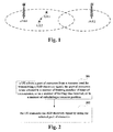
- FIG. 1 is a schematic diagram of D2D communications in the relevant art. As shown in FIG. 1 , D2D communications may be performed between UE1 and UE2 under coverage of a base station (eNB1). However, if under coverage of a base station, control signaling of the UE1 and UE2 will be sent by the base station.
- eNB1 base station
- a D2D discovery process such as mutual discovery between the UE1 and the UE2, needs to be performed.
- the UE1 needs to transmit a D2D discovery signal, which may also be referred to as a beacon, in a time-frequency resource; and the UE2 may discover the D2D discovery signal transmitted by the UE1 by detecting the time-frequency resource.
- quality of a channel from the UE1 to the UE2 may be known through signal detection.
- a UE1 and a UE2 always transmit D2D discovery signals in the same time-frequency resource, and they cannot discover each other.
- the UE does not know a time-frequency resource where a UE it expects to discover transmits a D2D discovery signal.
- the UE at the receiver end will perform blind detection, thereby increasing complexity of the UE, and resulting in relatively large power consumption and insufficient power saving.
- Embodiments of the present disclosure provide a method and apparatus for transmitting a D2D discovery signal and a communication system.
- Resources are selected by limiting the number of times of transmission or limiting a time interval, thereby avoiding malignant contention, and improving resource utilization; and resources are selected by calculating positions of the resources, thereby accurately performing detection, and lowering complexity of the UE.
- a method for transmitting a D2D discovery signal including:
- an apparatus for transmitting a D2D discovery signal including:
- a communication system including:
- a computer-readable program wherein when the program is executed in a UE, the program enables a computer to carry out the method for transmitting a D2D discovery signal as described above in the UE.
- a storage medium in which a computer-readable program is stored, wherein the computer-readable program enables a computer to carry out the method for transmitting a D2D discovery signal as described above in a UE.
- An advantage of the embodiments of the present disclosure exists in that resources for transmitting a D2D discovery signal are selected by limiting the number of times of transmission or limiting a time interval, thereby avoiding malignant contention, improving resource utilization, and lowering a probability of non-discovery between the UEs; and resources for transmitting a D2D discovery signal are selected by calculating positions of the resources, thereby accurately performing detection, and lowering complexity of the UE.
- FIG. 2 is a flowchart of the method for transmitting a D2D discovery signal of the embodiment of the present disclosure. As shown in FIG. 2 , the method includes:
- the resource pool for transmitting a D2D discovery signal may be configured by configuration information transmitted by a base station when the UE is in coverage of the base station, and may also be configured in advance when there exists no coverage of the base station, for example, the UE is configured in advance ex-works.
- the present disclosure is not limited thereto.
- the resource pool for transmitting a D2D discovery signal may include one of time-domain, frequency-domain or code-domain resources, or a combination thereof.
- FIG. 3 is a schematic diagram of the resource pool of the embodiment of the present disclosure. As shown in FIG. 3 , there are multiple subframe resources in a period T, and a part of the resources (such as a 2nd, a 4th, a 7th and a 9th subframes) may be resources available for transmitting a D2D discovery signal, which may form a resource pool for transmitting a D2D discovery signal. And the UE may select a part of the resources (such as the 2nd and the 7th subframes) to transmit a D2D discovery signal.
- FIG. 3 only schematically shows the resource pool for transmitting a D2D discovery signal; however, the present disclosure is not limited thereto.
- the resource pool may be one of a time-domain resource, a frequency-domain resource and a code-domain resource, or a combination thereof, and a particular content of the resource pool may be determined according to an actual situation.
- a part of resources in the resource pool (such as one or more subframe(s)) may be selected for transmitting a D2D discovery signal.
- the resource pool may be denoted by a bitmap.
- a length of the bitmap may denote the period T, 1 in the bitmap may denote available resources, and 0 in the bitmap may denote unavailable resources.
- the available resources denoted by the bitmap form the resource pool.
- the number of the available resources in the range of the period T can be seen from the bitmap, which may be denoted by m .
- the resource pool may be denoted by parameters.
- the parameters may include a period value and the number of the available resources, or may include the period value, the number of the available resources and position information on the available resources.
- a parameter period T and the number m of the available resources may be configured for the UE, and particular positions of m available resources may be predefined, such as defining former m subframes in the range of the period T.
- FIG. 4 is another flowchart of the method for transmitting a D2D discovery signal of the embodiment of the present disclosure. As shown in FIG. 4 , the method includes:
- the resource pool may be configured by an operation administration and maintenance (OAM) entity for one or more base station(s).
- OAM operation administration and maintenance
- Multiple base stations may be configured with the same resource pool, or multiple base stations may be configured different resource pools having overlapped resources; for example, positions of resources between neighboring base stations are ensured that there are overlapped parts; or multiple base stations may be configured different resource pools having no overlapped resources; for example, positions of resources between neighboring base stations are not overlapped.
- the base station may notify the configuration information of the resource pool to the UE in a broadcast or unicast manner; furthermore, the UE may receive an auxiliary parameter for selecting the part of resources transmitted by the base station; for example, besides the position information on the resource pool, other parameters may be contained, such as a maximum number of times of transmitting D2D discovery signals by the UE permitted in a time period, which may be denoted by n , or a minimum time interval between two times of transmitting D2D discovery signals, which may be denoted by t 1.
- Step 402 the UE selects a part of resources from the resource pool for transmitting a D2D discovery signal; the part of resources is/are selected in a manner of limiting number of times of transmission, or in a manner of limiting time interval, or in a manner of calculating a resource position.
- a random selection manner may be used; and the UE randomly selects one or more subframe(s) from the resource pool (such as available subframe resources) for transmitting a D2D discovery signal.
- the manner of limiting number of times may be used; in a case where the UE is covered by the base station, a network side may configure the UE with a limited number of times; for example, a maximum number of times of transmission of the UE in a time period (such as a cycle) is n ; and in a case where the UE is not covered by the base station, the parameters may be predefined, and the UE may select resources in a period to transmit D2D discovery signals for at most n times according to the parameters.
- the manner of limiting time interval may be used; in a case where the UE is covered by the base station, the network side may configure the UE with a maximum time interval between two times of transmitting D2D discovery signals; for example, a maximum time interval between two successive times of transmitting D2D discovery signals is t 1; and in a case where the UE is not covered by the base station, the parameters may be predefined, and the UE may select resources for transmitting a D2D discovery signal according to the parameters, so as to avoid that the time interval between two times of transmitting D2D discovery signals is less than t 1.
- the manner of calculating a resource position may be used, which may include: determining one or more subframe position(s) by using ID of the UE, and determining positions of radio frames, so as to determine a part of resources in the resource pool.
- the UE may learn parameters related to the resource pool which are configured based on the base station or preconfigured, including the period T and the number of available subframe resources in the range of the period T, the number being denoted by m.
- the ID of the UE may be ID uniquely identifying the UE; for example, it may be a cell radio network temporary identifier (C-RNTI), or proximity service (ProSe) UE_ID, or physical layer cell identity (PCI), or an evolved cell global identifier (ECGI); however, the present disclosure is not limited thereto, and other UE_ID may also be employed.
- C-RNTI cell radio network temporary identifier
- ProSe proximity service
- PCI physical layer cell identity
- ECGI evolved cell global identifier
- the positions of the radio frames may also be determined by using other methods.
- imax time-domain resource positions may be totally obtained. If the UE is permitted to transmit a D2D discovery signal once in each period, the UE transmits D2D discovery signals once respectively in imax periods. And if the UE is permitted to transmit multiple D2D discovery signals in each period, the UE may occupy imax time-domain positions obtained by using the method shown in Table 1 in a period to transmit D2D discovery signals.
- Step 403 the UE transmits the D2D discovery signal by using the selected part of resources.
- the UE may perform blink detection according to the resources configured by the base station or preconfigured resources.
- the UE of the receiver end may learn a particular position of the UE for transmitting the D2D discovery signals according to the configured parameters and the method shown in Table 1, and may receive the D2D discovery signals at accurate time-domain positions.
- the resources are selected by limiting the number of times of transmission or limiting a time interval, thereby avoiding malignant contention of resources, improving resource utilization, and lowering a probability of non-discovery between the UEs; and resources are selected by calculating positions of the resources, thereby accurately performing detection, and lowering complexity of the UE.
- An embodiment of the present disclosure provides an apparatus for transmitting a D2D discovery signal, which may be configured in a UE. This embodiment corresponds to the method for transmitting a D2D discovery signal described in Embodiment 1, with identical contents being not going to be described herein any further.
- FIG. 5 is a schematic diagram of a structure of the apparatus for transmitting a D2D discovery signal of the embodiment of the present disclosure.
- the apparatus 500 for transmitting a D2D discovery signal includes: a resource selecting unit 501 and a signal transmitting unit 502.
- the resource selecting unit 501 is configured to select a part of resources from a resource pool for transmitting a D2D discovery signal; the part of resources is/are selected in a manner of limiting number of times of transmission, or in a manner of limiting time interval, or in a manner of calculating a resource position; and the signal transmitting unit 502 is configured to transmit the D2D discovery signal by using the selected part of resources.
- the apparatus 500 for transmitting a D2D discovery signal may further include: a configuration receiving unit 503 configured to receive configuration information of the resource pool transmitted by a base station. Furthermore, the configuration receiving unit 403 may be configured to receive an auxiliary parameter for selecting the part of resources transmitted by the base station.
- the resource pool may be denoted by a bitmap, or may also be denoted by a parameter; however, the present disclosure is not limited thereto.
- the part of resources may be selected from the resource pool in a random manner, or the part of resources may be selected from the resource pool by limiting the number of times of transmission, or the part of resources may be selected from the resource pool by limiting a time interval. Furthermore, the part of resources may be selected from the resource pool by calculating positions of the resources.
- FIG. 6 is another schematic diagram of a structure of the apparatus for transmitting a D2D discovery signal of the embodiment of the present disclosure, in which the apparatus for transmitting in using the manner of calculating positions of the resources is shown.
- the apparatus 600 for transmitting a D2D discovery signal includes: a resource selecting unit 501, a signal transmitting unit 502 and a configuration receiving unit 503.
- the resource selecting unit 503 may further include a subframe determining unit 601 and a radio frame determining unit 602.
- the subframe determining unit 601 is configured to determine one or more subframe position(s) by using ID of the UE; and the radio frame determining unit 602 is configured to determine a position of a radio frame, so as to determine the part of resources in the resource pool.
- the apparatus for transmitting a D2D discovery signal may be configured in a UE.
- FIG. 7 is a block diagram of a systematic structure of the UE of an embodiment of the present disclosure.
- the UE 700 may include a central processing unit 100 and a memory 140, the memory 140 being coupled to the central processing unit 100.
- this figure is illustrative only, and other types of structures may also be used, so as to supplement or replace this structure and achieve telecommunications function or other functions.
- functions of the apparatus 500 or 600 for transmitting a D2D discovery signal may be integrated into the central processing unit 100.
- the central processing unit 100 may be configured to: select a part of resources from a resource pool for transmitting a D2D discovery signal; the part of resources is/are selected in a manner of limiting number of times of transmission, or in a manner of limiting time interval, or in a manner of calculating a resource position; and transmit the D2D discovery signal by using the selected part of resources.
- the apparatus 500 or 600 for transmitting a D2D discovery signal and the central processing unit 100 may be configured separately.
- the apparatus 500 or 600 for transmitting a D2D discovery signal may be configured as a chip connected to the central processing unit 100, with its functions being realized under control of the central processing unit 100.
- the UE 700 may further include a communication module 110, an input unit 120, an audio processor 130, a memory 140, a camera 150, a display 160, and a power supply 170.
- Functions of the above components are similar to those in the relevant art, which shall not described herein any further. It should be noted that the UE 700 does not necessarily include all the parts shown in FIG. 7 , and the above components are not necessary; and furthermore, the UE 700 may include parts not shown in FIG. 7 , and the relevant art may be referred to.
- the resources are selected by limiting the number of times of transmission or limiting a time interval, thereby avoiding malignant contention of resources, improving resource utilization, and lowering a probability of non-discovery between the UEs; and resources are selected by calculating positions of the resources, thereby accurately performing detection, and lowering complexity of the UE.
- An embodiment of the present disclosure provides a communication system, including the UE described in Embodiment 2.
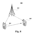
- FIG. 8 is a schematic diagram of a structure of the communication system of the embodiment of the present disclosure.
- the communication system 800 includes a base station 801, a first UE 802 and a second UE 803.
- the first UE 802 may be the UE 700 described in Embodiment 2.
- FIG. 8 shows a case where the first UE 802 and the second UE 803 are under coverage of the base station.
- the present disclosure is not limited thereto, and the first UE 802 and the second UE 803 may also not be covered the base station.
- the first UE 802 and the second UE 803 may be covered by different base stations, and a particular scenario may be determined according to an actual situation.
- An embodiment of the present disclosure further provides a computer-readable program, when the program is executed in a UE, the program enables a computer to carry out the method for transmitting a D2D discovery signal as described in Embodiment 1 in the UE.
- An embodiment of the present disclosure provides a storage medium in which a computer-readable program is stored, the computer-readable program enables a computer to carry out the method for transmitting a D2D discovery signal as described in Embodiment 1 in a UE.
- the above apparatuses and methods of the present disclosure may be implemented by hardware, or by hardware in combination with software.
- the present disclosure relates to such a computer-readable program that when the program is executed by a logic device, the logic device is enabled to carry out the apparatus or components as described above, or to carry out the methods or steps as described above.
- the present disclosure also relates to a storage medium for storing the above program, such as a hard disk, a floppy disk, a CD, a DVD, and a flash memory, etc.
- One or more functional blocks and/or one or more combinations of the functional blocks in Figures may be realized as a universal processor, a digital signal processor (DSP), an application-specific integrated circuit (ASIC), a field programmable gate array (FPGA) or other programmable logic devices, discrete gate or transistor logic devices, discrete hardware component or any appropriate combinations thereof. And they may also be realized as a combination of computing equipment, such as a combination of a DSP and a microprocessor, multiple processors, one or more microprocessors in communication combination with a DSP, or any other such configuration.
- DSP digital signal processor
- ASIC application-specific integrated circuit
- FPGA field programmable gate array
Abstract
Description
- The present disclosure relates to the field of communications, and in particular to a method and apparatus for transmitting a device-to-device (D2D) discovery signal and a communication system.
- A D2D communication method refers to that data packets are communicated by directly establishing a communication link between user equipments (UEs), such as a UE1 and a UE2, without needing via a core network, even without needing via a base station.
FIG. 1 is a schematic diagram of D2D communications in the relevant art. As shown inFIG. 1 , D2D communications may be performed between UE1 and UE2 under coverage of a base station (eNB1). However, if under coverage of a base station, control signaling of the UE1 and UE2 will be sent by the base station. - Before D2D direct communications can be established between UEs, a D2D discovery process, such as mutual discovery between the UE1 and the UE2, needs to be performed. For example, in order to achieve discovery of the UE1 by the UE2, the UE1 needs to transmit a D2D discovery signal, which may also be referred to as a beacon, in a time-frequency resource; and the UE2 may discover the D2D discovery signal transmitted by the UE1 by detecting the time-frequency resource. And quality of a channel from the UE1 to the UE2 may be known through signal detection.
- It should be noted that the above description of the background is merely provided for clear and complete explanation of the present disclosure and for easy understanding by those skilled in the art. And it should not be understood that the above technical solution is known to those skilled in the art as it is described in the background of the present disclosure.
- However, it was discovered by the inventors that according to a conclusion of a discussion of the current 3GPP, there exist the following problems in an existing discovery mechanism: when a large number of UEs need to transmit D2D discovery signals at a time period, they need to acquire time-frequency resources through contention; and when a UE cannot determine whether the D2D discovery signal is transmitted successfully, in order to improve a rate of success of transmission, the UE will frequently occupy a large number of resources through contention to transmit the D2D discovery signal, thereby resulting in malignant contention, and lowering resource utilization.
- Furthermore, as simultaneous receiving and transmission in the same time-frequency resource cannot be performed by a UE, it is prone that some UEs always cannot discover each other. For example, a UE1 and a UE2 always transmit D2D discovery signals in the same time-frequency resource, and they cannot discover each other.
- Furthermore, for a UE at a receiver end, the UE does not know a time-frequency resource where a UE it expects to discover transmits a D2D discovery signal. Hence, the UE at the receiver end will perform blind detection, thereby increasing complexity of the UE, and resulting in relatively large power consumption and insufficient power saving.
- Embodiments of the present disclosure provide a method and apparatus for transmitting a D2D discovery signal and a communication system. Resources are selected by limiting the number of times of transmission or limiting a time interval, thereby avoiding malignant contention, and improving resource utilization; and resources are selected by calculating positions of the resources, thereby accurately performing detection, and lowering complexity of the UE.
- According to an aspect of the embodiments of the present disclosure, there is provided a method for transmitting a D2D discovery signal, including:
- selecting a part of resources by a UE from a resource pool for transmitting a D2D discovery signal; wherein, the part of resources is/are selected in a manner of limiting number of times of transmission, or in a manner of limiting time interval, or in a manner of calculating a resource position; and
- transmitting the D2D discovery signal by using the selected part of resources.
- According to another aspect of the embodiments of the present disclosure, there is provided an apparatus for transmitting a D2D discovery signal, including:
- a resource selecting unit configured to select a part of resources from a resource pool for transmitting a D2D discovery signal; wherein, the part of resources is/are selected in a manner of limiting number of times of transmission, or in a manner of limiting time interval, or in a manner of calculating a resource position; and
- a signal transmitting unit configured to transmit the D2D discovery signal by using the selected part of resources.
- According to a further aspect of the embodiments of the present disclosure, there is provided a communication system, including:
- a first UE configured to select a part of resources from a resource pool for transmitting a D2D discovery signal; wherein, the part of resources is/are selected in a manner of limiting number of times of transmission, or in a manner of limiting time interval, or in a manner of calculating a resource position; and transmit the D2D discovery signal by using the selected part of resources; and
- a second UE configured to perform blind detection according to the resource pool for transmitting the D2D discovery signal to receive the D2D discovery signal, or configured to receive the D2D discovery signal in a selected resource in a manner of calculating a resource position.
- According to still another aspect of the embodiments of the present disclosure, there is provided a computer-readable program, wherein when the program is executed in a UE, the program enables a computer to carry out the method for transmitting a D2D discovery signal as described above in the UE.
- According to still another aspect of the embodiments of the present disclosure, there is provided a storage medium in which a computer-readable program is stored, wherein the computer-readable program enables a computer to carry out the method for transmitting a D2D discovery signal as described above in a UE.
- An advantage of the embodiments of the present disclosure exists in that resources for transmitting a D2D discovery signal are selected by limiting the number of times of transmission or limiting a time interval, thereby avoiding malignant contention, improving resource utilization, and lowering a probability of non-discovery between the UEs; and resources for transmitting a D2D discovery signal are selected by calculating positions of the resources, thereby accurately performing detection, and lowering complexity of the UE.
- With reference to the following description and drawings, the particular embodiments of the present disclosure are disclosed in detail, and the principle of the present disclosure and the manners of use are indicated. It should be understood that the scope of the embodiments of the present disclosure is not limited thereto. The embodiments of the present disclosure contain many alternations, modifications and equivalents within the scope of the terms of the appended claims.
- Features that are described and/or illustrated with respect to one embodiment may be used in the same way or in a similar way in one or more other embodiments and/or in combination with or instead of the features of the other embodiments.
- It should be emphasized that the term "comprise/include" when used in this specification is taken to specify the presence of stated features, integers, steps or components but does not preclude the presence or addition of one or more other features, integers, steps, components or groups thereof.
- Many aspects of the disclosure can be better understood with reference to the following drawings. The components in the drawings are not necessarily to scale, emphasis instead being placed upon clearly illustrating the principles of the present disclosure. To facilitate illustrating and describing some parts of the disclosure, corresponding portions of the drawings may be exaggerated in size.
- Elements and features depicted in one drawing or embodiment of the disclosure may be combined with elements and features depicted in one or more additional drawings or embodiments. Moreover, in the drawings, like reference numerals designate corresponding parts throughout the several views and may be used to designate like or similar parts in more than one embodiments.
-
FIG. 1 is a schematic diagram of D2D communications in the relevant art; -
FIG. 2 is a flowchart of the method for transmitting a D2D discovery signal of an embodiment of the present disclosure; -
FIG. 3 is a schematic diagram of a resource pool of an embodiment of the present disclosure; -
FIG. 4 is another flowchart of the method for transmitting a D2D discovery signal of the embodiment of the present disclosure; -
FIG. 5 is a schematic diagram of a structure of the apparatus for transmitting a D2D discovery signal of an embodiment of the present disclosure; -
FIG. 6 is another schematic diagram of a structure of the apparatus for transmitting a D2D discovery signal of the embodiment of the present disclosure; -
FIG. 7 is a block diagram of a systematic structure of the UE of an embodiment of the present disclosure; and -
FIG. 8 is a schematic diagram of a structure of the communication system of an embodiment of the present disclosure. - These and further aspects and features of the present disclosure will be apparent with reference to the following description and attached drawings. In the description and drawings, particular embodiments of the disclosure have been disclosed in detail as being indicative of some of the ways in which the principles of the disclosure may be employed, but it is understood that the disclosure is not limited correspondingly in scope. Rather, the disclosure includes all changes, modifications and equivalents coming within the terms of the appended claims.
- An embodiment of the present disclosure provides a method for transmitting a D2D discovery signal, which is described from a UE side of a transmitter end performing D2D communications.
FIG. 2 is a flowchart of the method for transmitting a D2D discovery signal of the embodiment of the present disclosure. As shown inFIG. 2 , the method includes: - step 201: a UE selects a part of resources from a resource pool for transmitting a D2D discovery signal; the part of resources is/are selected in a manner of limiting number of times of transmission, or in a manner of limiting time interval, or in a manner of calculating a resource position; and
- step 202: the UE transmits the D2D discovery signal by using the selected part of resources.
- In this embodiment, the resource pool for transmitting a D2D discovery signal may be configured by configuration information transmitted by a base station when the UE is in coverage of the base station, and may also be configured in advance when there exists no coverage of the base station, for example, the UE is configured in advance ex-works. However, the present disclosure is not limited thereto.
- In this embodiment, the resource pool for transmitting a D2D discovery signal may include one of time-domain, frequency-domain or code-domain resources, or a combination thereof.
FIG. 3 is a schematic diagram of the resource pool of the embodiment of the present disclosure. As shown inFIG. 3 , there are multiple subframe resources in a period T, and a part of the resources (such as a 2nd, a 4th, a 7th and a 9th subframes) may be resources available for transmitting a D2D discovery signal, which may form a resource pool for transmitting a D2D discovery signal. And the UE may select a part of the resources (such as the 2nd and the 7th subframes) to transmit a D2D discovery signal. - It should be noted that
FIG. 3 only schematically shows the resource pool for transmitting a D2D discovery signal; however, the present disclosure is not limited thereto. The resource pool may be one of a time-domain resource, a frequency-domain resource and a code-domain resource, or a combination thereof, and a particular content of the resource pool may be determined according to an actual situation. A part of resources in the resource pool (such as one or more subframe(s)) may be selected for transmitting a D2D discovery signal. - In this embodiment, the resource pool may be denoted by a bitmap. A length of the bitmap may denote the period T, 1 in the bitmap may denote available resources, and 0 in the bitmap may denote unavailable resources. The available resources denoted by the bitmap form the resource pool. The number of the available resources in the range of the period T can be seen from the bitmap, which may be denoted by m.
- Alternatively, the resource pool may be denoted by parameters. The parameters may include a period value and the number of the available resources, or may include the period value, the number of the available resources and position information on the available resources. For example, a parameter period T and the number m of the available resources, may be configured for the UE, and particular positions of m available resources may be predefined, such as defining former m subframes in the range of the period T.
- It should be noted that expression manners of the resource pool are schematically described above only; however, the present disclosure is not limited thereto. The present disclosure shall be further described below taking that the UE is covered by the base station as an example.
-
FIG. 4 is another flowchart of the method for transmitting a D2D discovery signal of the embodiment of the present disclosure. As shown inFIG. 4 , the method includes: - step 401: a UE receives configuration information on the resource pool transmitted by a base station.
- In this embodiment, the resource pool may be configured by an operation administration and maintenance (OAM) entity for one or more base station(s).
- Multiple base stations may be configured with the same resource pool, or multiple base stations may be configured different resource pools having overlapped resources; for example, positions of resources between neighboring base stations are ensured that there are overlapped parts; or multiple base stations may be configured different resource pools having no overlapped resources; for example, positions of resources between neighboring base stations are not overlapped.
- In this embodiment, the base station may notify the configuration information of the resource pool to the UE in a broadcast or unicast manner; furthermore, the UE may receive an auxiliary parameter for selecting the part of resources transmitted by the base station; for example, besides the position information on the resource pool, other parameters may be contained, such as a maximum number of times of transmitting D2D discovery signals by the UE permitted in a time period, which may be denoted by n, or a minimum time interval between two times of transmitting D2D discovery signals, which may be denoted by t1.
- Step 402: the UE selects a part of resources from the resource pool for transmitting a D2D discovery signal; the part of resources is/are selected in a manner of limiting number of times of transmission, or in a manner of limiting time interval, or in a manner of calculating a resource position.
- In an implementation, a random selection manner may be used; and the UE randomly selects one or more subframe(s) from the resource pool (such as available subframe resources) for transmitting a D2D discovery signal.
- In another implementation, the manner of limiting number of times may be used; in a case where the UE is covered by the base station, a network side may configure the UE with a limited number of times; for example, a maximum number of times of transmission of the UE in a time period (such as a cycle) is n; and in a case where the UE is not covered by the base station, the parameters may be predefined, and the UE may select resources in a period to transmit D2D discovery signals for at most n times according to the parameters.
- In a further implementation, the manner of limiting time interval may be used; in a case where the UE is covered by the base station, the network side may configure the UE with a maximum time interval between two times of transmitting D2D discovery signals; for example, a maximum time interval between two successive times of transmitting D2D discovery signals is t1; and in a case where the UE is not covered by the base station, the parameters may be predefined, and the UE may select resources for transmitting a D2D discovery signal according to the parameters, so as to avoid that the time interval between two times of transmitting D2D discovery signals is less than t1.
- In still another implementation, the manner of calculating a resource position may be used, which may include: determining one or more subframe position(s) by using ID of the UE, and determining positions of radio frames, so as to determine a part of resources in the resource pool.
- Taking the manner of parameters of the resource pool as an example, the UE may learn parameters related to the resource pool which are configured based on the base station or preconfigured, including the period T and the number of available subframe resources in the range of the period T, the number being denoted by m.
- In this implementation, the ID of the UE, UE_ID, may be ID uniquely identifying the UE; for example, it may be a cell radio network temporary identifier (C-RNTI), or proximity service (ProSe) UE_ID, or physical layer cell identity (PCI), or an evolved cell global identifier (ECGI); however, the present disclosure is not limited thereto, and other UE_ID may also be employed.
- Furthermore, before being used, the UE_ID may be preliminarily processed; for example, UE_ID = UE_ID_original mod 1024, that is, modulo operation is performed on original ID; and this scheme may be applied to selection of time-domain resources.
- In this implementation, the method for determining one or more subframe position(s) by using the UE_ID may be as expressed in Table 1:
Table 1 (1) selecting a q0-th subframe from m available subframes; where, m is the number of subframes in the resource pool, and q0 is determined by using the formula below: UE_ID = m *p0 + q 0 , 0 ≤ q 0 < m; where, UE_ID is the ID of the UE, and p 0 and q 0 are positive integers; (2) selecting a (1+q1)-th subframe in the m available subframes; where, p 0= m * p 1 + q 1, 0 ≤ q 1 < m; and if 1+ q 1=m, a 0-th subframe will be selected; ...... (i) selecting a (1+qi-1)-th subframe in the m available subframes; where, p i-2 = m * p i-1 + q i-1, 0 ≤ q i-1 < m; and 2 ≤ i ≤ imax, m (imax-1) ≤ UE_ID ≤ m (imax), p i-1, q i-1 and i being positive integers; and if 1+ q i-1=m, a 0-th subframe will be selected. - Following description shall be given by way of examples. Assuming that UE_ID=100, m =64, then p 0= 1, q 0=36; a 36th subframe in the m available subframes may be selected for transmitting D2D discovery signals. It can be determined from UE_ID=100, m =64 that imax=2, thereby determining p 1=0, q 1=1; and furthermore, a 2nd subframe in the m available subframes may be selected for transmitting D2D discovery signals.
- Assuming that UE_ID=100, m =8, then p 0= 12, q 0=4; a 4th subframe in the m available subframes may be selected for transmitting D2D discovery signals. It can be determined from UE_ID=100, m =8 that imax=3, thereby determining p 1=1, q 1=4; and furthermore, a 5th subframe in the m available subframes may be selected for transmitting D2D discovery signals. And it may be determined that p 2= 0, q 2=1, and a 2nd subframe in the m available subframes may be selected for transmitting D2D discovery signals.
- In this implementation, determination of positions of the radio frames may be as follows: determining a first position of a time-domain resource for transmitting a D2D discovery signal as a system frame number (SFN), which is 0, and a subframe number is also 0. For the period T (less than 10240 ms), its unit might be assumed as millisecond (ms), and a starting point of a time-domain position of the resource for transmitting a D2D discovery signal satisfies (SFN*10 mod T) = 0. However, the present disclosure is not limited thereto. For example, the positions of the radio frames may also be determined by using other methods.
- In this implementation, imax time-domain resource positions may be totally obtained. If the UE is permitted to transmit a D2D discovery signal once in each period, the UE transmits D2D discovery signals once respectively in imax periods. And if the UE is permitted to transmit multiple D2D discovery signals in each period, the UE may occupy imax time-domain positions obtained by using the method shown in Table 1 in a period to transmit D2D discovery signals.
- Step 403: the UE transmits the D2D discovery signal by using the selected part of resources.
- In this embodiment, at the receiver end, the UE may perform blink detection according to the resources configured by the base station or preconfigured resources. Alternatively, if the transmitter end transmits D2D discovery signals in the manner of calculating a resource position, the UE of the receiver end may learn a particular position of the UE for transmitting the D2D discovery signals according to the configured parameters and the method shown in Table 1, and may receive the D2D discovery signals at accurate time-domain positions.
- It can be seen from the embodiment that the resources are selected by limiting the number of times of transmission or limiting a time interval, thereby avoiding malignant contention of resources, improving resource utilization, and lowering a probability of non-discovery between the UEs; and resources are selected by calculating positions of the resources, thereby accurately performing detection, and lowering complexity of the UE.
- An embodiment of the present disclosure provides an apparatus for transmitting a D2D discovery signal, which may be configured in a UE. This embodiment corresponds to the method for transmitting a D2D discovery signal described in
Embodiment 1, with identical contents being not going to be described herein any further. -
FIG. 5 is a schematic diagram of a structure of the apparatus for transmitting a D2D discovery signal of the embodiment of the present disclosure. As shown inFIG. 5 , theapparatus 500 for transmitting a D2D discovery signal includes: aresource selecting unit 501 and asignal transmitting unit 502. - The
resource selecting unit 501 is configured to select a part of resources from a resource pool for transmitting a D2D discovery signal; the part of resources is/are selected in a manner of limiting number of times of transmission, or in a manner of limiting time interval, or in a manner of calculating a resource position; and thesignal transmitting unit 502 is configured to transmit the D2D discovery signal by using the selected part of resources. - As shown in
FIG. 5 , theapparatus 500 for transmitting a D2D discovery signal may further include: aconfiguration receiving unit 503 configured to receive configuration information of the resource pool transmitted by a base station. Furthermore, theconfiguration receiving unit 403 may be configured to receive an auxiliary parameter for selecting the part of resources transmitted by the base station. - In this embodiment, the resource pool may be denoted by a bitmap, or may also be denoted by a parameter; however, the present disclosure is not limited thereto.
- In this embodiment, the part of resources may be selected from the resource pool in a random manner, or the part of resources may be selected from the resource pool by limiting the number of times of transmission, or the part of resources may be selected from the resource pool by limiting a time interval. Furthermore, the part of resources may be selected from the resource pool by calculating positions of the resources.
-
FIG. 6 is another schematic diagram of a structure of the apparatus for transmitting a D2D discovery signal of the embodiment of the present disclosure, in which the apparatus for transmitting in using the manner of calculating positions of the resources is shown. As shown inFIG. 6 , theapparatus 600 for transmitting a D2D discovery signal includes: aresource selecting unit 501, asignal transmitting unit 502 and aconfiguration receiving unit 503. - The
resource selecting unit 503 may further include asubframe determining unit 601 and a radioframe determining unit 602. Thesubframe determining unit 601 is configured to determine one or more subframe position(s) by using ID of the UE; and the radioframe determining unit 602 is configured to determine a position of a radio frame, so as to determine the part of resources in the resource pool. - In this embodiment, the apparatus for transmitting a D2D discovery signal may be configured in a UE.
-
FIG. 7 is a block diagram of a systematic structure of the UE of an embodiment of the present disclosure. As shown inFIG. 7 , theUE 700 may include acentral processing unit 100 and amemory 140, thememory 140 being coupled to thecentral processing unit 100. It should be noted that this figure is illustrative only, and other types of structures may also be used, so as to supplement or replace this structure and achieve telecommunications function or other functions. - In an implementation, functions of the
apparatus central processing unit 100. Thecentral processing unit 100 may be configured to: select a part of resources from a resource pool for transmitting a D2D discovery signal; the part of resources is/are selected in a manner of limiting number of times of transmission, or in a manner of limiting time interval, or in a manner of calculating a resource position; and transmit the D2D discovery signal by using the selected part of resources. - In an implementation, the
apparatus central processing unit 100 may be configured separately. For example, theapparatus central processing unit 100, with its functions being realized under control of thecentral processing unit 100. - As shown in
FIG. 7 , theUE 700 may further include acommunication module 110, aninput unit 120, anaudio processor 130, amemory 140, acamera 150, adisplay 160, and apower supply 170. Functions of the above components are similar to those in the relevant art, which shall not described herein any further. It should be noted that theUE 700 does not necessarily include all the parts shown inFIG. 7 , and the above components are not necessary; and furthermore, theUE 700 may include parts not shown inFIG. 7 , and the relevant art may be referred to. - It can be seen from the embodiment that the resources are selected by limiting the number of times of transmission or limiting a time interval, thereby avoiding malignant contention of resources, improving resource utilization, and lowering a probability of non-discovery between the UEs; and resources are selected by calculating positions of the resources, thereby accurately performing detection, and lowering complexity of the UE.
- An embodiment of the present disclosure provides a communication system, including the UE described in Embodiment 2.
-
FIG. 8 is a schematic diagram of a structure of the communication system of the embodiment of the present disclosure. As shown inFIG. 8 , thecommunication system 800 includes abase station 801, afirst UE 802 and asecond UE 803. Thefirst UE 802 may be theUE 700 described in Embodiment 2. - The
first UE 802 is configured to select a part of resources from a resource pool for transmitting a D2D discovery signal; the part of resources is/are selected in a manner of limiting number of times of transmission, or in a manner of limiting time interval, or in a manner of calculating a resource position; and transmit the D2D discovery signal by using the selected part of resources; - and the
second UE 803 is configured to perform blind detection according to the resource pool for transmitting the D2D discovery signal to receive the D2D discovery signal, or configured to receive the D2D discovery signal in a selected resource in a manner of calculating a resource position. - It should be noted that
FIG. 8 shows a case where thefirst UE 802 and thesecond UE 803 are under coverage of the base station. However, the present disclosure is not limited thereto, and thefirst UE 802 and thesecond UE 803 may also not be covered the base station. Furthermore, thefirst UE 802 and thesecond UE 803 may be covered by different base stations, and a particular scenario may be determined according to an actual situation. - An embodiment of the present disclosure further provides a computer-readable program, when the program is executed in a UE, the program enables a computer to carry out the method for transmitting a D2D discovery signal as described in
Embodiment 1 in the UE. - An embodiment of the present disclosure provides a storage medium in which a computer-readable program is stored, the computer-readable program enables a computer to carry out the method for transmitting a D2D discovery signal as described in
Embodiment 1 in a UE. - The above apparatuses and methods of the present disclosure may be implemented by hardware, or by hardware in combination with software. The present disclosure relates to such a computer-readable program that when the program is executed by a logic device, the logic device is enabled to carry out the apparatus or components as described above, or to carry out the methods or steps as described above. The present disclosure also relates to a storage medium for storing the above program, such as a hard disk, a floppy disk, a CD, a DVD, and a flash memory, etc.
- One or more functional blocks and/or one or more combinations of the functional blocks in Figures may be realized as a universal processor, a digital signal processor (DSP), an application-specific integrated circuit (ASIC), a field programmable gate array (FPGA) or other programmable logic devices, discrete gate or transistor logic devices, discrete hardware component or any appropriate combinations thereof. And they may also be realized as a combination of computing equipment, such as a combination of a DSP and a microprocessor, multiple processors, one or more microprocessors in communication combination with a DSP, or any other such configuration.
- The present disclosure is described above with reference to particular embodiments. However, it should be understood by those skilled in the art that such a description is illustrative only, and not intended to limit the protection scope of the present disclosure. Various variants and modifications may be made by those skilled in the art according to the principles of the present disclosure, and such variants and modifications fall within the scope of the present disclosure.
Claims (20)
- A method for transmitting a D2D discovery signal, comprising:selecting, by a UE, a part of resources from a resource pool for transmitting a D2D discovery signal; wherein, the part of resources is/are selected in a manner of limiting number of times of transmission, or in a manner of limiting time interval, or in a manner of calculating a resource position; andtransmitting the D2D discovery signal by using the selected part of resources.
- The method according to claim 1, wherein the method further comprises:receiving configuration information on the resource pool transmitted by a base station.
- The method according to claim 2, wherein the resource pool is configured for one or more base station(s) by an operation administration and maintenance (OAM) entity.
- The method according to claim 3, wherein the base stations are configured with identical resource pools, or the base stations are configured with different resource pools having overlapped resources, or the base stations are configured with different resource pools having no overlapped resource.
- The method according to claim 1, wherein the resource pool is indicated by a bitmap.
- The method according to claim 5, wherein a length of the bitmap denotes a period, 1 in the bitmap denotes available resources, and 0 in the bitmap denotes unavailable resources, the available resources denoted by the bitmap forming the resource pool.
- The method according to claim 1, wherein the resource pool is indicated by parameters.
- The method according to claim 7, wherein the parameters comprise a period and a number of available resources; or comprise the period, the number of available resources and information on positions of the available resources.
- The method according to claim 2, wherein the method further comprises:receiving an auxiliary parameter for selecting the part of resources transmitted by the base station.
- The method according to claim 9, wherein in a case where the part of resources is/are selected in a manner of limiting number of times of transmission, the auxiliary parameter comprises: permitted number of times of transmission by the UE in a period of time.
- The method according to claim 9, wherein in a case where the part of resources is/are selected in a manner of limiting time interval, the auxiliary parameter comprises: a minimum time interval between two times of transmission.
- The method according to claim 1, wherein in a case where the part of resources is/are selected a manner of calculating a resource position, the method further comprises:determining one or more subframe position(s) by using ID of the UE; anddetermining a position of a radio frame to determine the part of resources in the resource pool.
- The method according to claim 12, wherein the determining one or more subframe position(s) by using ID of the UE comprises:selecting a q 0-th subframe from m available subframes;where, m is the number of subframes in the resource pool, and q 0 is determined by using the formula: UE_ID = m * p 0 + q 0, 0 ≤ q 0 < m, where, UE_ID is the ID of the UE, and p 0 and q 0 are positive integers.
- The method according to claim 13, wherein the determining one or more subframe position(s) by using ID of the UE further comprises:selecting a (1+qi-1 )-th subframe from m available subframes;where, pi-2 = m * p i-1 + q i-1, 0 ≤ q i-1 < m, and 2 ≤ i ≤ imax, m (imax-1)≤UE_ID ≤ m (imax) , p i-1, q i-1 and i are positive integers; andselecting a 0-th subframe from m available subframes if 1+ q i-1=m.
- An apparatus for transmitting D2D discovery signal, comprising:a resource selecting unit configured to select a part of resources from a resource pool for transmitting a D2D discovery signal; wherein, the part of resources is/are selected in a manner of limiting number of times of transmission, or in a manner of limiting time interval, or in a manner of calculating a resource position; anda signal transmitting unit configured to transmit the D2D discovery signal by using the selected part of resources.
- The apparatus according to claim 15, wherein the apparatus further comprises:a configuration receiving unit configured to receive configuration information of the resource pool transmitted by a base station.
- The apparatus according to claim 16, wherein the configuration receiving unit is further configured to receive an auxiliary parameter for selecting the part of resources transmitted by the base station.
- The apparatus according to claim 15, wherein the resource pool is indicated by a bitmap, or the resource pool is indicated by parameters.
- The apparatus according to claim 15, wherein the resource selecting unit further comprises:a subframe determining unit configured to determine one or more subframe position(s) by using ID of the UE; anda radio frame determining unit configured to determine a position of a radio frame to determine the part of resources in the resource pool.
- A communication system, comprising:a first UE configured to select a part of resources from a resource pool for transmitting a D2D discovery signal; wherein, the part of resources is/are selected in a manner of limiting number of times of transmission, or in a manner of limiting time interval, or in a manner of calculating a resource position; and transmit the D2D discovery signal by using the selected part of resources; anda second UE configured to perform blind detection according to the resource pool for transmitting the D2D discovery signal to receive the D2D discovery signal, or configured to receive the D2D discovery signal in a selected resource in a manner of calculating a resource position.
Applications Claiming Priority (1)
| Application Number | Priority Date | Filing Date | Title |
|---|---|---|---|
| PCT/CN2013/088770 WO2015081561A1 (en) | 2013-12-06 | 2013-12-06 | Method and apparatus for sending d2d discovery signal, and communications system |
Publications (2)
| Publication Number | Publication Date |
|---|---|
| EP3079420A1 true EP3079420A1 (en) | 2016-10-12 |
| EP3079420A4 EP3079420A4 (en) | 2017-05-31 |
Family
ID=53272780
Family Applications (1)
| Application Number | Title | Priority Date | Filing Date |
|---|---|---|---|
| EP13898517.1A Ceased EP3079420A4 (en) | 2013-12-06 | 2013-12-06 | Method and apparatus for sending d2d discovery signal, and communications system |
Country Status (9)
| Country | Link |
|---|---|
| US (2) | US10716051B2 (en) |
| EP (1) | EP3079420A4 (en) |
| JP (1) | JP2017504242A (en) |
| KR (2) | KR20180107321A (en) |
| CN (3) | CN110830977A (en) |
| CA (1) | CA2932451A1 (en) |
| MX (1) | MX2016007306A (en) |
| RU (1) | RU2649851C2 (en) |
| WO (1) | WO2015081561A1 (en) |
Cited By (1)
| Publication number | Priority date | Publication date | Assignee | Title |
|---|---|---|---|---|
| EP4236600A3 (en) * | 2016-05-12 | 2023-09-13 | Sony Group Corporation | Communication device, communication method and computer program |
Families Citing this family (12)
| Publication number | Priority date | Publication date | Assignee | Title |
|---|---|---|---|---|
| EP3079422B1 (en) * | 2013-12-27 | 2018-03-21 | Huawei Technologies Co., Ltd. | Method and apparatus for allocating device-to-device (d2d) communications resource |
| CN105940738B (en) * | 2014-01-29 | 2020-03-17 | Lg电子株式会社 | D2D operation method performed by terminal in wireless communication system and terminal using the same |
| WO2015171049A1 (en) * | 2014-05-05 | 2015-11-12 | Telefonaktiebolaget L M Ericsson (Publ) | Method and devices for unidirectional device-to-device communication |
| JP6427207B2 (en) * | 2014-06-16 | 2018-11-21 | エルジー エレクトロニクス インコーポレイティド | Method and apparatus for signal transmission / reception of device-to-device terminal in wireless communication system |
| EP3179802B1 (en) | 2014-08-07 | 2020-07-08 | LG Electronics Inc. | Device-to-device (d2d) operation method performed by terminal in wireless communications system and terminal using same |
| CN106559873B (en) * | 2015-09-25 | 2021-10-22 | 中兴通讯股份有限公司 | Information sending method and device |
| WO2017071726A1 (en) * | 2015-10-26 | 2017-05-04 | Nokia Solutions And Networks Oy | User equipment assisted coordination for scheduled wireless transmissions |
| CN107005851B (en) | 2015-10-27 | 2019-11-12 | 华为技术有限公司 | A kind of device-to-device D2D communication means, apparatus and system |
| US10531334B2 (en) | 2016-06-28 | 2020-01-07 | International Business Machines Corporation | Determining a transmission number for a device |
| US9961527B2 (en) * | 2016-06-30 | 2018-05-01 | Verizon Patent And Licensing Inc. | Access control and scheduling mechanism for MTC devices |
| EP3499994A4 (en) | 2016-08-11 | 2020-04-22 | LG Electronics Inc. -1- | Method whereby terminal transmits data to another terminal in wireless communication system |
| WO2018084569A1 (en) * | 2016-11-01 | 2018-05-11 | 엘지전자 주식회사 | Method and device for deriving location information by means of receiving gps signal in wireless communication system |
Family Cites Families (24)
| Publication number | Priority date | Publication date | Assignee | Title |
|---|---|---|---|---|
| US20090149221A1 (en) * | 2004-09-08 | 2009-06-11 | Utstarcom Telecom Co., Ltd. | Centralized base station system based on advanced telecommunication computer architecture platform |
| JPWO2008146494A1 (en) * | 2007-05-29 | 2010-08-19 | 三菱電機株式会社 | Calibration method, communication system, and frequency control method |
| KR101416994B1 (en) * | 2007-06-26 | 2014-07-08 | 삼성전자주식회사 | Apparatus and method for allocation of frequency resources in wireless telecommunication system |
| CN101355724B (en) * | 2007-07-26 | 2012-04-18 | 中兴通讯股份有限公司 | Method and apparatus for reducing information transmission conflict in mobile communication system |
| US7990941B2 (en) * | 2007-07-30 | 2011-08-02 | Freescale Semiconductor, Inc. | Adaptive antenna system signal detection |
| US7979769B2 (en) * | 2008-04-14 | 2011-07-12 | Lg Electronics Inc. | Method and apparatus for performing random access procedures |
| US8121097B2 (en) | 2008-11-04 | 2012-02-21 | Qualcomm Incorporated | Transmission with hopping for peer-peer communication |
| US8107883B2 (en) | 2009-03-23 | 2012-01-31 | Nokia Corporation | Apparatus and method for interference avoidance in mixed device-to-device and cellular environment |
| CN103002452B (en) * | 2011-09-14 | 2016-08-10 | 华为技术有限公司 | For reducing the method for inter-cell signal interference, base station and wireless communication system |
| WO2013049959A1 (en) * | 2011-10-02 | 2013-04-11 | Renesas Mobile Corporation | Signaling for device-to-device wireless communication |
| US20150057006A1 (en) * | 2011-11-08 | 2015-02-26 | Chunyan Gao | Method and Apparatus for D2D Transmission |
| US9332562B2 (en) * | 2011-12-07 | 2016-05-03 | Sony Corporation | Radio base station, communication control method of radio base station and computer program |
| GB2497589A (en) * | 2011-12-16 | 2013-06-19 | Renesas Mobile Corp | Resource Allocation in a Wireless Communication System |
| CN103379617B (en) * | 2012-04-26 | 2016-08-10 | 华为技术有限公司 | A kind of subscriber equipment is to the communication means of subscriber equipment and subscriber equipment |
| CN103428679A (en) * | 2012-05-14 | 2013-12-04 | 中国移动通信集团公司 | D2D communication method, device and system |
| CN103428817B (en) * | 2012-05-23 | 2016-08-03 | 华为技术有限公司 | D2D method for discovering equipment based on LTE cellular communication system and device |
| JP5957617B2 (en) * | 2012-12-09 | 2016-07-27 | エルジー エレクトロニクス インコーポレイティド | Synchronization acquisition method and apparatus for direct communication between a coverage internal terminal and a coverage external terminal in a wireless communication system |
| CN103338497B (en) * | 2013-06-14 | 2016-06-01 | 北京交通大学 | Autonomous device discover method in a kind of D2D communication system |
| JP6549110B2 (en) * | 2013-07-01 | 2019-07-24 | エルジー エレクトロニクス インコーポレイティド | Method for direct communication between idle mode terminals using pseudo random access procedure and apparatus therefor |
| WO2015009123A1 (en) * | 2013-07-19 | 2015-01-22 | 엘지전자 주식회사 | Method for detecting search signal for device-to-device (d2d) communication in wireless communication system, and apparatus therefor |
| SG11201600892XA (en) * | 2013-08-07 | 2016-03-30 | Interdigital Patent Holdings | Distributed scheduling for device-to-device communication |
| WO2015050394A1 (en) * | 2013-10-02 | 2015-04-09 | 엘지전자 주식회사 | Method and apparatus for transmitting signal from device-to-device terminal in wireless communication system |
| US10165555B2 (en) * | 2013-10-03 | 2018-12-25 | Lg Electronics Inc. | Method and apparatus for transmitting indication for device-to-device operation in wireless communication system |
| US9572171B2 (en) | 2013-10-31 | 2017-02-14 | Intel IP Corporation | Systems, methods, and devices for efficient device-to-device channel contention |
-
2013
- 2013-12-06 MX MX2016007306A patent/MX2016007306A/en unknown
- 2013-12-06 RU RU2016125847A patent/RU2649851C2/en not_active IP Right Cessation
- 2013-12-06 KR KR1020187027242A patent/KR20180107321A/en not_active Application Discontinuation
- 2013-12-06 EP EP13898517.1A patent/EP3079420A4/en not_active Ceased
- 2013-12-06 JP JP2016536529A patent/JP2017504242A/en active Pending
- 2013-12-06 CN CN201911075013.4A patent/CN110830977A/en active Pending
- 2013-12-06 KR KR1020167014170A patent/KR20160079048A/en active Application Filing
- 2013-12-06 CN CN201380080633.1A patent/CN105706508A/en active Pending
- 2013-12-06 WO PCT/CN2013/088770 patent/WO2015081561A1/en active Application Filing
- 2013-12-06 CN CN202010737008.1A patent/CN111836364A/en active Pending
- 2013-12-06 CA CA2932451A patent/CA2932451A1/en not_active Abandoned
-
2016
- 2016-06-03 US US15/173,010 patent/US10716051B2/en active Active
-
2020
- 2020-02-06 US US16/783,772 patent/US10841865B2/en active Active
Cited By (1)
| Publication number | Priority date | Publication date | Assignee | Title |
|---|---|---|---|---|
| EP4236600A3 (en) * | 2016-05-12 | 2023-09-13 | Sony Group Corporation | Communication device, communication method and computer program |
Also Published As
| Publication number | Publication date |
|---|---|
| CA2932451A1 (en) | 2015-06-11 |
| CN110830977A (en) | 2020-02-21 |
| US10841865B2 (en) | 2020-11-17 |
| JP2017504242A (en) | 2017-02-02 |
| KR20160079048A (en) | 2016-07-05 |
| US20200178159A1 (en) | 2020-06-04 |
| US10716051B2 (en) | 2020-07-14 |
| RU2649851C2 (en) | 2018-04-05 |
| CN111836364A (en) | 2020-10-27 |
| WO2015081561A1 (en) | 2015-06-11 |
| EP3079420A4 (en) | 2017-05-31 |
| US20160286465A1 (en) | 2016-09-29 |
| MX2016007306A (en) | 2016-08-04 |
| KR20180107321A (en) | 2018-10-01 |
| CN105706508A (en) | 2016-06-22 |
Similar Documents
| Publication | Publication Date | Title |
|---|---|---|
| US10841865B2 (en) | Method and apparatus for transmitting D2D discovery signal and communication system | |
| EP3096481B1 (en) | Signal transmission method and apparatus | |
| WO2022028450A1 (en) | Method and apparatus for reporting ai network model support capability, method and apparatus for receiving ai network model support capability, and storage medium, user equipment and base station | |
| WO2020038331A1 (en) | Method and apparatus for determining uplink resource | |
| WO2019047599A1 (en) | Method and apparatus for determining ra-rnti | |
| WO2021032027A1 (en) | Random access method, terminal device and network device | |
| WO2014106498A1 (en) | Preamble sequence transmission method, device and system | |
| WO2018067063A1 (en) | Controlling validity time of uplink grant in target cell during rach-less handover | |
| US10327229B2 (en) | Data reception method, data transmission method and data reception device for device-to-device communication | |
| TWI812691B (en) | A method, a network device, and a terminal device for transmitting a signal | |
| CN105407532B (en) | D2D communication method and device | |
| US20220225425A1 (en) | Random Access Method And Apparatus | |
| WO2017197949A1 (en) | Control method for data transmission, and relevant device | |
| CN109462894B (en) | Apparatus and method for controlling uplink transmission timing in an internet of things environment | |
| WO2015127619A1 (en) | Method and device for transmitting and receiving system information | |
| TW201838466A (en) | Device and Method of Handling a Measurement Gap in a Wireless Communication System | |
| US20210321386A1 (en) | Transmission feedback method and user equipment | |
| WO2021026929A1 (en) | Communication method and apparatus | |
| WO2017166023A1 (en) | Random access method and apparatus | |
| US11012835B2 (en) | Method and terminal for acquiring transmission resource in vehicle to everything | |
| WO2019090478A1 (en) | Transmission time determination method and device, and computer storage medium | |
| EP3703445B1 (en) | Data transmission method, terminal device and network device | |
| CN108271257B (en) | Resource allocation method and device | |
| JP2023546606A (en) | Communication methods and devices | |
| TW201911936A (en) | Apparatus and method for processing random access program |
Legal Events
| Date | Code | Title | Description |
|---|---|---|---|
| PUAI | Public reference made under article 153(3) epc to a published international application that has entered the european phase |
Free format text: ORIGINAL CODE: 0009012 |
|
| 17P | Request for examination filed |
Effective date: 20160531 |
|
| AK | Designated contracting states |
Kind code of ref document: A1 Designated state(s): AL AT BE BG CH CY CZ DE DK EE ES FI FR GB GR HR HU IE IS IT LI LT LU LV MC MK MT NL NO PL PT RO RS SE SI SK SM TR |
|
| AX | Request for extension of the european patent |
Extension state: BA ME |
|
| DAX | Request for extension of the european patent (deleted) | ||
| A4 | Supplementary search report drawn up and despatched |
Effective date: 20170503 |
|
| RIC1 | Information provided on ipc code assigned before grant |
Ipc: H04W 76/02 20090101ALN20170425BHEP Ipc: H04W 8/00 20090101AFI20170425BHEP |
|
| RAP1 | Party data changed (applicant data changed or rights of an application transferred) |
Owner name: FUJITSU CONNECTED TECHNOLOGIES LIMITED |
|
| STAA | Information on the status of an ep patent application or granted ep patent |
Free format text: STATUS: EXAMINATION IS IN PROGRESS |
|
| 17Q | First examination report despatched |
Effective date: 20190122 |
|
| STAA | Information on the status of an ep patent application or granted ep patent |
Free format text: STATUS: EXAMINATION IS IN PROGRESS |
|
| REG | Reference to a national code |
Ref country code: DE Ref legal event code: R003 |
|
| STAA | Information on the status of an ep patent application or granted ep patent |
Free format text: STATUS: THE APPLICATION HAS BEEN REFUSED |
|
| 18R | Application refused |
Effective date: 20220313 |