EP3079337B1 - Event correlation across heterogeneous operations - Google Patents
Event correlation across heterogeneous operations Download PDFInfo
- Publication number
- EP3079337B1 EP3079337B1 EP16164616.1A EP16164616A EP3079337B1 EP 3079337 B1 EP3079337 B1 EP 3079337B1 EP 16164616 A EP16164616 A EP 16164616A EP 3079337 B1 EP3079337 B1 EP 3079337B1
- Authority
- EP
- European Patent Office
- Prior art keywords
- data
- potential attack
- alerts
- alert
- network
- Prior art date
- Legal status (The legal status is an assumption and is not a legal conclusion. Google has not performed a legal analysis and makes no representation as to the accuracy of the status listed.)
- Active
Links
- 230000000694 effects Effects 0.000 claims description 135
- 238000000034 method Methods 0.000 claims description 59
- 238000004891 communication Methods 0.000 claims description 40
- 230000009471 action Effects 0.000 claims description 21
- 238000012800 visualization Methods 0.000 claims description 16
- 230000002776 aggregation Effects 0.000 claims description 14
- 238000004220 aggregation Methods 0.000 claims description 14
- 238000010586 diagram Methods 0.000 claims description 12
- 230000001131 transforming effect Effects 0.000 claims 3
- 230000002123 temporal effect Effects 0.000 claims 2
- 238000005516 engineering process Methods 0.000 description 129
- 230000000875 corresponding effect Effects 0.000 description 37
- 238000001914 filtration Methods 0.000 description 33
- 238000012545 processing Methods 0.000 description 24
- 230000004931 aggregating effect Effects 0.000 description 16
- 238000001514 detection method Methods 0.000 description 16
- 238000007726 management method Methods 0.000 description 14
- 238000004590 computer program Methods 0.000 description 13
- 230000004044 response Effects 0.000 description 11
- 238000012795 verification Methods 0.000 description 9
- 230000008569 process Effects 0.000 description 8
- 238000000605 extraction Methods 0.000 description 7
- 238000004458 analytical method Methods 0.000 description 6
- 230000002596 correlated effect Effects 0.000 description 6
- 230000006870 function Effects 0.000 description 5
- 238000002372 labelling Methods 0.000 description 4
- 238000012544 monitoring process Methods 0.000 description 4
- 230000002265 prevention Effects 0.000 description 4
- 230000008901 benefit Effects 0.000 description 3
- 230000003993 interaction Effects 0.000 description 3
- 230000003287 optical effect Effects 0.000 description 3
- 230000002547 anomalous effect Effects 0.000 description 2
- 230000008859 change Effects 0.000 description 2
- 238000012423 maintenance Methods 0.000 description 2
- 230000007246 mechanism Effects 0.000 description 2
- 238000009877 rendering Methods 0.000 description 2
- 238000013515 script Methods 0.000 description 2
- 238000000926 separation method Methods 0.000 description 2
- 230000000007 visual effect Effects 0.000 description 2
- 208000018208 Hyperimmunoglobulinemia D with periodic fever Diseases 0.000 description 1
- 206010072219 Mevalonic aciduria Diseases 0.000 description 1
- 241001354471 Pseudobahia Species 0.000 description 1
- 230000002155 anti-virotic effect Effects 0.000 description 1
- 230000005540 biological transmission Effects 0.000 description 1
- 230000000903 blocking effect Effects 0.000 description 1
- 230000003247 decreasing effect Effects 0.000 description 1
- 238000009434 installation Methods 0.000 description 1
- 239000004973 liquid crystal related substance Substances 0.000 description 1
- 230000007935 neutral effect Effects 0.000 description 1
- 238000010606 normalization Methods 0.000 description 1
- 230000002093 peripheral effect Effects 0.000 description 1
- 230000000644 propagated effect Effects 0.000 description 1
- 230000010076 replication Effects 0.000 description 1
- 239000004065 semiconductor Substances 0.000 description 1
- 230000001953 sensory effect Effects 0.000 description 1
- 239000000758 substrate Substances 0.000 description 1
- 230000008685 targeting Effects 0.000 description 1
- DTXLBRAVKYTGFE-UHFFFAOYSA-J tetrasodium;2-(1,2-dicarboxylatoethylamino)-3-hydroxybutanedioate Chemical compound [Na+].[Na+].[Na+].[Na+].[O-]C(=O)C(O)C(C([O-])=O)NC(C([O-])=O)CC([O-])=O DTXLBRAVKYTGFE-UHFFFAOYSA-J 0.000 description 1
- 238000012546 transfer Methods 0.000 description 1
- 230000001960 triggered effect Effects 0.000 description 1
Images


Classifications
-
- H—ELECTRICITY
- H04—ELECTRIC COMMUNICATION TECHNIQUE
- H04L—TRANSMISSION OF DIGITAL INFORMATION, e.g. TELEGRAPHIC COMMUNICATION
- H04L63/00—Network architectures or network communication protocols for network security
- H04L63/14—Network architectures or network communication protocols for network security for detecting or protecting against malicious traffic
- H04L63/1433—Vulnerability analysis
-
- H—ELECTRICITY
- H04—ELECTRIC COMMUNICATION TECHNIQUE
- H04L—TRANSMISSION OF DIGITAL INFORMATION, e.g. TELEGRAPHIC COMMUNICATION
- H04L63/00—Network architectures or network communication protocols for network security
- H04L63/02—Network architectures or network communication protocols for network security for separating internal from external traffic, e.g. firewalls
- H04L63/0227—Filtering policies
-
- H—ELECTRICITY
- H04—ELECTRIC COMMUNICATION TECHNIQUE
- H04L—TRANSMISSION OF DIGITAL INFORMATION, e.g. TELEGRAPHIC COMMUNICATION
- H04L63/00—Network architectures or network communication protocols for network security
- H04L63/14—Network architectures or network communication protocols for network security for detecting or protecting against malicious traffic
- H04L63/1408—Network architectures or network communication protocols for network security for detecting or protecting against malicious traffic by monitoring network traffic
- H04L63/1425—Traffic logging, e.g. anomaly detection
-
- H—ELECTRICITY
- H04—ELECTRIC COMMUNICATION TECHNIQUE
- H04L—TRANSMISSION OF DIGITAL INFORMATION, e.g. TELEGRAPHIC COMMUNICATION
- H04L67/00—Network arrangements or protocols for supporting network services or applications
- H04L67/01—Protocols
- H04L67/10—Protocols in which an application is distributed across nodes in the network
Definitions
- the present disclosure relates to security and network operations.
- one innovative aspect of the subject matter described in this specification can be embodied in methods for correlating domain activity, including receiving first domain activity data from a first network domain and second domain activity data from a second network domain, the first domain activity data and the second domain activity data including events, alerts, or both from the respective first and second network domains, filtering the first domain activity data and the second domain activity data to remove irrelevant activity data, based on a first set of profile data for devices in the first network domain and a second set of profile data for devices in the second network domain, aggregating unfiltered first domain activity data and unfiltered second domain activity data, correlating aggregated unfiltered first domain activity data and unfiltered second domain activity data to determine an attack path for an attack that occurs across the first network domain and the second network domain, based on attack signatures and profiles associated with previously identified attacks, and generating a visualization of the attack path.
- inventions of this aspect include corresponding computer methods, and include corresponding apparatus and computer programs recorded on one or more computer storage devices, each configured to perform the actions of the methods.
- a system of one or more computers can be configured to perform particular operations or actions by virtue of having software, firmware, hardware, or a combination of them installed on the system that in operation causes or cause the system to perform the actions.
- One or more computer programs can be configured to perform particular operations or actions by virtue of including instructions that, when executed by data processing apparatus, cause the apparatus to perform the actions.
- the first domain activity data, the second domain activity data, or both can include log data provided by one or more security sensors.
- the first network domain can be an information technology network domain and the second network domain can be an operational technology network domain.
- the filtering can include determining, for each event or alert, a corresponding attack and a corresponding target, determining, based on profile data for the corresponding target, that the attack on the target is rendered unsuccessful, and filtering the corresponding event or alert.
- the filtering can include, for each unfiltered event or alert, dynamically retrieving current status information about the corresponding target, determining, based the current status information about the corresponding target, that the attack on the target is rendered unsuccessful, and filtering the corresponding event or alert.
- a single vantage point and a standardized data exchange format may be provided for analyzing event/alert log data from information technology (IT) and operational technology (OT) networks.
- IT information technology
- OT operational technology
- security sensors e.g., intrusion detection systems (IDS), intrusion prevention systems (IPS), and other suitable security sensors
- IDS intrusion detection systems
- IPS intrusion prevention systems
- False alarm rates may be reduced in an event detection process.
- Multi-step, multi-domain threat scenarios may be detected and/or constructed. Complex scenarios may be visually represented, and network status may be shown at each step of an attack.
- Threat intelligence platforms/services may be integrated to further enrich and contextualize information and constructed scenarios.
- an industrial internet may be used to manage and administer industrial control systems (ICS), which may communicate over an enterprise network and may include information technology (IT) and operational technology (OT) domains.
- ICS industrial control systems
- IT information technology
- OT operational technology
- Some threat scenarios may include multi-step, multi-domain attacks, and may include attacks that originate in one domain, and proceed to another domain.
- filtering, aggregating, and correlating data from event/alert logs from each domain e.g., IT and OT domains
- Information about the attack patterns e.g., visualization data
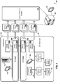
- FIG. 1 depicts an example system 100 that can execute implementations of the present disclosure.
- the system 100 e.g., an industrial control system
- the system 100 includes multiple network domains, including an information technology (IT) network domain 102 (e.g., including an enterprise network) and an operational technology (OT) network domain 104.
- the information technology network domain 102 and the operational technology network domain 104 can be in communication, for example, over a demilitarized zone (DMZ) 106a of the information technology network domain 102 and a demilitarized zone (DMZ) 106b of the operational technology network domain 104.
- DMZ demilitarized zone
- DMZ demilitarized zone
- Each of the network domains 102 and 104 may include local and wide area networks (LAN/WAN) and wireless networks, and can be used to integrate various computing devices, such as servers, mainframes, desktops, laptops, tablets, smartphones, and industrial control devices and sensors, that may run on multiple different operating systems and may employ multiple different communication protocols.
- LAN/WAN local and wide area networks
- computing devices such as servers, mainframes, desktops, laptops, tablets, smartphones, and industrial control devices and sensors, that may run on multiple different operating systems and may employ multiple different communication protocols.
- the information technology network domain 102 can include various computing devices (e.g., computing server 112), input/output devices (e.g., interface device 114), and/or subsystems.
- the computing server 112 can include one or more processors configured to execute instructions stored by computer-readable media for performing various operations, such as input/output, communication, data processing, and/or data maintenance.
- a user can employ the interface device 114 (e.g., including one or more presentation components, such as a display, and one or more input components such as a keyboard, mouse, and/or touchpad).
- the operational technology network domain 104 can include various computing devices, input/output devices, and/or subsystems.
- the operational technology network domain 104 includes a supervisory system 120, a historian server 122, an application server 124, one or more human-machine interface (HMI) devices (e.g., HMI device 126), and one or more controller devices (e.g., controller device 128) and sensor devices (e.g., sensor device 130).
- HMI human-machine interface
- controller devices e.g., controller device 128, and sensor devices (e.g., sensor device 130).
- the supervisory system 120 can coordinate one or more low-level controls and/or low-level sensors.
- the supervisory system 120 can provide data to and receive data from the controller device 128 and the sensor device 130.
- the historian server 122 can store, maintain, and provide information related to activities performed by each controller device and sensor data provided by each sensor device in the operational technology network domain 104.
- the application server 124 can host applications that may operate within the operational technology network domain 104.
- the system 100 may include one or more security sensors (e.g., security sensors 108a, 108b, 108c, and 108d).
- security sensors included in the system 100 may include network based (NIDS) and host based (HIDS) intrusion detection systems, intrusion prevention systems (IPS), anti-virus systems, firewalls, and other detection/logging services (e.g., web server logs, database logs, etc.) which can monitor communications activity to and from computing devices included in the industrial technology (IT) network domain 102, the IT DMZ 106a, the operational technology (OT) network domain 104, and/or the OT DMZ 106b, and can monitor system activity associated with the devices.
- IT industrial technology
- IT operational technology
- OT operational technology
- Data associated with potentially malicious activity may be detected (and optionally, recorded) by the security sensors 108a, 108b, 108c, and 108d (e.g., as event/alert data, log files, etc.), and/or other detection/logging devices included in the system 100, and/or may be provided to other components of the system 100.
- activity data 140a, 140b, 140c, and 140d e.g., detected by the corresponding security sensors 108a, 108b, 108c, and 108d
- Such activity data may also be provided to an event correlation system 150 by a Security Information and Event Management (SIEM) system.
- SIEM Security Information and Event Management
- the activity data 140a may include enterprise data from the information technology network domain 102, provided by host-based monitoring systems (e.g., intrusion detection/prevention systems, web server logging services, system logs, etc.) and/or network-based monitoring systems (e.g., intrusion detection/prevention systems, firewalls, routers, etc.).
- the activity data 140b may include data associated with communication over the IT DMZ 106a.
- the activity data 140c for example, may include data associated with communication over the OT DMZ 106b.
- the activity data 140d may include supervisory data, control layer data, and/or sensor and controller device data from the operational technology network domain 104, provided by host-based monitoring systems and/or network-based monitoring systems.
- each of the activity data 140a, 140b, 140c, and 140d may include event and/or alert data.
- events are atomic pieces of data associated with communications and system activity, whereas alerts may be triggered in response to an event or a sequence of events.
- Data provided by the security sensors 108a, 108b, 108c, and 108d, for example, may include alert data.
- Data provided by a host (e.g., the computing server 112), controller device (e.g., the controller device 128) or sensor device (e.g., the sensor device 130), or data included in log files, for example, may include event data.
- the event correlation system 150 can receive the activity data 140a, 140b, 140c, and 140d from multiple domains (e.g., the information technology (IT) network domain 102, the IT DMZ 106a, the operational technology (OT) network domain 104, and the OT DMZ 106b), and can standardize, filter, aggregate, and correlate the data to detect anomalies and potentially malicious activity associated with multi-stage, multi-domain attacks.
- the event correlation system 150 can include various computing devices (e.g., computing server 152), input/output devices (e.g., interface device 154), and/or subsystems.
- the computing server 152 can include one or more processors configured to execute instructions stored by computer-readable media for performing various operations, such as input/output, communication, data processing, and/or data maintenance.
- a user can employ the interface device 154 (e.g., including one or more presentation components, such as a display, and one or more input components such as a keyboard, mouse, and/or touchpad).
- output may be provided by the event correlation system 150 to another system (e.g., a security information and event management (SIEM) system) and/or to a system operator as reporting/visualization data.
- SIEM security information and event management
- appropriate courses of action may be employed to counter ongoing and/or future attacks.
- the information technology (IT) network domain 102, the IT DMZ 106a, the operational technology (OT) network domain 104, and the OT DMZ 106b each has different characteristics (e.g., architecture, resources, protocols, and standards), and each domain may be susceptible to different security threats.
- correlations may not be detected among events/alerts within a single domain, (and if correlations are detected, an extent of an associated compromise may not be entirely known), but correlations may be detected among events/alerts across multiple domains.
- complex attacks e.g., multi-stage, multi-domain attacks executed over time
- a single vantage point may be provided to security technicians.
- FIG. 2 depicts an example system 200 that can execute implementations of the present disclosure.
- the system 200 includes an event correlation system 202 (e.g., similar to the event correlation system 150, shown in FIG. 1 ).
- the event correlation system 202 can include various hardware and/or software-based components (e.g., software modules, objects, engines, libraries, etc.) including an information technology (IT) activity data filter 210, an operational technology (OT) activity data filter 212, an aggregator 214, a correlator 216, a pattern recognizer 218, a response generator 220, and an operator input/output (I/O) component 222.
- IT information technology
- OT operational technology
- I/O operator input/output
- Various data sources may maintain data used by the system 200 and its components.
- the system 200 can receive information from an information technology (IT) network data source 230, an operational technology (OT) network data source 232, and a threat intelligence data source 234.
- Activity data associated with a demilitarized zone (DMZ) or peripheral network may be provided by the information technology network data source 230 and/or the operational technology network data source 232.
- IT information technology
- OT operational technology
- DMZ demilitarized zone
- peripheral network for example, may be provided by the information technology network data source 230 and/or the operational technology network data source 232.
- system 200 and its various components can perform functions for processing event/alert data received from various sources, aggregating the data, correlating the data, detecting patterns in the data, and providing relevant information to system operators and/or other systems.
- components 210, 212, 214, 216, 218, 220, and 222 can perform functions for processing event/alert data received from various sources, aggregating the data, correlating the data, detecting patterns in the data, and providing relevant information to system operators and/or other systems.
- the event correlation system 202 can receive information technology (IT) activity data 240 that includes event/alert data from an information technology network (e.g., the information technology (IT) network domain 102, and optionally the IT DMZ 106a, shown in FIG. 1 ), and can receive operational technology (OT) activity data 242 that includes event/alert data from an operational technology network (e.g., the operational technology (OT) network domain 104, and optionally the OT DMZ 106b, shown in FIG. 1 ).
- IT information technology
- OT operational technology
- the information technology activity data 240 and/or the operational technology activity data 242 may include log data provided by one or more security sensors (e.g., the security sensors 108a, 108b, 108c, and 108d, shown in FIG. 1 ).
- the event correlation system 202 can use the information technology activity data filter 210 to filter out irrelevant (or "false") events/alerts, based on data provided by the information technology network data source 230.
- the event correlation system 202 can use the operational technology activity data filter 212 to filter out irrelevant (or "false") events/alerts, based on data provided by the operational technology network data source 232. Operation of the information technology activity data filter 210 and the operational technology activity data filter 212 is discussed in further detail below in association with FIG. 3 .
- filtered event/alert data can be provided by the information technology activity data filter 210 and the operational technology activity data filter 212 to the aggregator 214.
- the event correlation system 202 can use the aggregator 214 to remove duplicate and/or redundant events/alerts, to combine events/alerts related to the same attack, and to combine events/alerts relating to different attacks but possessing similar characteristics, thus reducing the number of events/alerts under consideration.
- the aggregator 214 may reference data provided by the information technology network data source 230 and/or the operational technology network data source 232 when performing aggregation operations. Operation of the aggregator 214 is discussed in further detail below in association with FIG. 4A .
- aggregated data can be provided by the aggregator 214 to the correlator 216.
- the event correlation system 202 can use the correlator 216 to generate a chain of events/alerts that may correspond to a threat scenario, and the event correlation system 202 can use the pattern recognizer 218 (e.g., based on data provide by the threat intelligence data source 234) to identify attack patterns associated with the threat scenario, and to further describe and/or enrich threat scenario information.
- the response generator 220 can provide appropriate courses of action for responding to threats to the information technology network 250 and the operational technology network 252. Operation of the correlator 216 and the pattern recognizer 218 is discussed in further detail below in association with FIG. 5A .
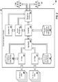
- FIG. 3 depicts an example system 300 that can execute implementations of the present disclosure.
- the system 300 includes a filtering and verification system 302 (e.g., corresponding to the information technology activity data filter 210 and the operational technology activity data filter 212, shown in FIG. 2 ).
- the filtering and verification system 302 can include various hardware and/or software-based components (e.g., software modules, objects, engines, libraries, etc.) including a rule-based filter 310 for information technology (IT) activity data, a rule-based filter 312 for operational technology (OT) activity data, an optional verifier 320 for information technology (IT) activity data, and an optional verifier 322 for operational technology (OT) activity data.
- the system 300 includes an information technology (IT) network data source 330 (e.g., including configuration management information associated with devices in the information technology (IT) network domain 102, shown in FIG. 1 ), an operational technology (OT) network data source 332 (e.g., including configuration management information associated with devices in the operational technology (OT) network domain 104, shown in FIG. 1 ), and a filtered alerts data source 336.
- IT information technology
- OT operational technology
- the system 300 and its various components e.g., components 310, 312, 320, and 322
- the filtering and verification system 302 can receive information technology (IT) activity data 340 that includes event/alert data from an information technology network, and optionally, a corresponding DMZ (e.g., the information technology (IT) network domain 102 and the IT DMZ 106a, shown in FIG. 1 ), and can receive operational technology (OT) activity data 342 that includes event/alert data from an operational technology network, and optionally, a corresponding DMZ (e.g., the operational technology (OT) network domain 104 and the DMZ 106b, shown in FIG. 1 ).
- IT information technology
- OT operational technology
- the information technology activity data 340 and/or the operational technology activity data 342 may include log data provided by one or more security sensors (e.g., security sensors 108a, 108b, 108c, and 108d, shown in FIG. 1 ).
- security sensors e.g., security sensors 108a, 108b, 108c, and 108d, shown in FIG. 1 .
- activity data received from multiple sources may be heterogeneous in regard to language, protocols, and standards.
- Such activity data may be heterogeneous, for example, not only because of different security tools in a single domain (which may be resolved through the use of alert/event standardization/normalization tools that convert data to a standard format), but because of different protocol standards which may be employed in multiple different domains by the same security tool.
- a standard format may be used for communicating activity data.
- the filtering and verification system 302 can use the rule-based filter 310 for information technology activity data to filter out irrelevant (or "false") events/alerts, based on data provided by the information technology network data source 330 (e.g., similar to the information technology network data source 230, shown in FIG. 2 ), and in conjunction with additional rules that may be defined by system administrators.
- the filtering and verification system 302 can use the rule-based filter 312 for operational technology activity data to filter out irrelevant (or "false") events/alerts, based on data provided by the operational technology network database 332 (e.g., similar to the operational technology network data source 232, shown in FIG. 2 ), and in conjunction with additional rules that may be defined by system administrators.
- the operational technology network database 332 e.g., similar to the operational technology network data source 232, shown in FIG. 2
- rule-based filtering performed by each of the rule-based filters 310 and 312 can remove irrelevant events/alerts (e.g., events/alerts that are not determined to be associated with a potential attack) based on a target's profile and/or characteristics of the events/alerts.
- Rule-based filtering may apply to defined rules that discard particular events/alerts (e.g., false positives) based on how frequently events/alerts with certain characteristics occur, and their relative rate of change with regard to occurrence.
- Profile data for potential targets e.g., computing devices
- an appropriate rule-based filter may reference profile data from an appropriate network data source for a target that corresponds to the event/alert (e.g., based on device address), and can determine whether the received event/alert indicates a potential attack.
- a network-based intrusion detection system may not have specific information about an attacker or about a target, but may generate an alert based on the contents of a communications packet - that is, the alert may be generated if the packet includes an exploit directed to a known vulnerability.
- the generated alert in the present example may or may not indicate a successful attack on the target. For example, if an attack relies on certain system attributes (e.g., a type of operating system), but the system has different attributes (e.g., a different operating system) that are not affected by an attempted attack, the attack is rendered unsuccessful.
- the network drops the communications packet, rendering the packet ineffective and the attack unsuccessful.
- the number of events/alerts under consideration may be reduced, thus reducing the amount of processing in subsequent stages.
- profile data and/or statuses of potential targets may be dynamically determined when filtering received events/alerts.
- the filtering and verification system 302 can optionally use the verifier 320 to dynamically verify profile data for a target on the information technology network domain 102 (shown in FIG. 1 ), and the filtering and verification system 302 can optionally use the verifier 322 to dynamically verify profile data for a target on the operational technology network domain 104 (shown in FIG. 1 ).
- an appropriate verifier can determine whether dynamically retrieved information regarding a target corresponding to the event/alert (e.g., based on device address) indicates that the event/alert is associated with actual malicious activity. For example, for an unfiltered event/alert corresponding to a target on the information technology network domain 102, the verifier 320 can communicate with a system/network scanner 350 (e.g., with access to configuration management information) to receive current information about the target. In the present example, a communications packet may be directed to an open port on the target, and the rule-based filter 310 may not filter the corresponding alert.
- the verifier 320 may determine that the target has been patched to counter an attack associated with the alert, for example, rendering the communications packet ineffective and the attack unsuccessful.
- the alert may be filtered out and/or labeled as a potentially unsuccessful attack.
- the verifier 322 can communicate with a device virtualization component 352 to receive current information about the target.
- a communications packet may be directed to changing a setting (e.g., a temperature setting, an on/off setting, a power level, a position, etc.) on the target (e.g., a controller device).
- the device virtualization component 352 can query the target (or one or more sensors associated with the target) for its status to determine an effect of the communications packet.
- a negative effect for example, may indicate a potentially successful attack, whereas a neutral effect or lack of an effect may indicate a potentially unsuccessful attack.
- the filtering and verification system 302 can record filtered alert data associated with potentially unsuccessful attacks and/or false positives (e.g., in the filtered alerts data source 336), and can provide data associated with potential attacks for further processing.
- the alerts 360 may be indicative of potential attacks on an information technology network (e.g., the information technology network domain 102, shown in FIG. 1 ) and the alerts 362 may be indicative of potential attacks on an operational technology network (e.g., the operational technology network domain 104, shown in FIG. 1 ).
- Data maintained by the filtered alerts data source 336 may be used for generating future security policies, as is discussed in further detail below in association with FIG. 5A .
- FIG. 4A depicts an example system 400 that can execute implementations of the present disclosure.
- the system 400 includes an alert aggregation system 402 (e.g., corresponding to the aggregator 214, shown in FIG. 2 ).
- the alert aggregation system 402 can include various hardware and/or software-based components (e.g., software modules, objections, engines, libraries, etc.) including an alert fuser 410 and an alert aggregator 412.
- the system 400 and its various components e.g., components 410 and 412) can perform functions for processing and aggregating event/alert data received from various different sources.
- aggregating event/alert data for example, data redundancy can be decreased, and the aggregated event/alert data may be further processed to identify trends and correlations in the data.
- the aggregation system 402 can receive alert data 420 corresponding to potential attacks on an information technology network (e.g., the information technology network domain 102, shown in FIG. 1 ) and alert data 422 corresponding to potential attacks on an operational technology network (e.g., the operational technology network domain 104, shown in FIG. 1 ).
- an information technology network e.g., the information technology network domain 102, shown in FIG. 1
- alert data 422 corresponding to potential attacks on an operational technology network
- the aggregation system 402 can use the fuser 410 to combine similar alerts, which may have been generated by different intrusion detection systems, security tools and/or sensors.
- a malicious packet may be detected by each of the intrusion detection systems, and each of the systems may generate a similar alert in response to detecting the packet.
- each of the similar alerts may include similar data, yet may have slightly different timestamps (e.g., due to network traffic speeds).
- the fuser 410 determines that multiple alerts are related (e.g., the alerts were generated in response to the same packet or event based on having similar data and having timestamps within a threshold similarity value), for example, the multiple alerts may be combined into a meta-alert.
- the fuser 410 can provide meta-alerts 430 and raw alerts 432 (i.e., uncombined alerts) to the alert aggregator 412.
- alert aggregator 412 can aggregate the sets of alerts 430 and 432, based on data similarities.
- alert aggregation may include combining alerts that have similar characteristics, which may indicate launch from and/or targeting of one or more computing devices.
- an attack may include the scanning of particular computing devices included in an information technology network and computing devices included in an operational technology network, by multiple attackers.
- alerts from the information technology network and alerts from the operational technology network may be aggregated to reflect that the alerts are associated with the same type of attack.
- each of the sets of alerts 430 and 432 may have similar data formats (e.g., an intrusion detection message exchange format (IDMEF)), and may include data fields for source address, destination address, port number, timestamp, priority, and attack description.
- IDM intrusion detection message exchange format
- alert aggregator 412 determines that two or more of the meta-alerts 430 and/or the raw alerts 432 are similar based on criteria that pertains to data included in each alert (e.g., two or more alerts have the same destination address (and optionally, port number) and have timestamps within a threshold similarity value, two or more alerts have the same source address and have timestamps within a threshold similarity value, two or more alerts are targeted to similar services, or another suitable criteria based on similarity of alert attributes), for example, the alert aggregator 412 may aggregate the alerts.
- criteria that pertains to data included in each alert e.g., two or more alerts have the same destination address (and optionally, port number) and have timestamps within a threshold similarity value, two or more alerts have the same source address and have timestamps within a threshold similarity value, two or more alerts are targeted to similar services, or another suitable criteria based on similarity of alert attributes
- the alert aggregator 412 may determine that a large or very large number of alerts are related (e.g. hundreds, thousands, or more alerts) and aggregate those alerts into a single record or data structure that facilitates efficient processing of a large volume of alert data.
- the alert aggregation system 402 can provide aggregated alerts 440 and non-aggregated alerts 442 as a combined set of meta and raw alerts 450 for further processing.
- the alert aggregation system 402 can also generate and store a data structure that represents both aggregated alerts and a relationship between different aggregated alerts, for example, based on a source and destination address in the aggregated alert. Once generated and stored, the data structure (described in greater detail below) can be further processed by the system, such as event correlation system 150 and system 500. In some implementations, the aggregated alerts 440 can be provided by the alert aggregation system 402 to an event analysis and management system 460 for further analysis.
- FIG. 4B depicts an example data structure 480 that can be used by implementations of the present disclosure once it is generated and stored by the alert aggregation system 402.
- the data structure 480 e.g., a directed graph
- the data structure 480 can be generated and used to represent the meta and raw alerts 450 provided by the alert aggregation system 402.
- Nodes (e.g., node 482, node 484) in the data structure 480 can represent entities referenced in the meta and raw alerts 450, such as computing devices/assets (e.g., devices/assets within the information technology (IT) network domain 102, the IT DMZ 106a, the operational technology (OT) network domain 104, and the OT DMZ 106b), internet protocol (IP) addresses, and ports.
- Edges (e.g., edge 486) in the data structure 480 can represent relationships between the entities (e.g., an aggregated event occurring between two entities).
- the edge 486 can represent a communication event (e.g., including a timestamp) between an originating computing device (e.g., a server) represented by the node 482 and a destination computing device (e.g., a DMZ server) represented by the node 484, and can be directed from the node 482 to the node 484.
- a communication event e.g., including a timestamp
- an originating computing device e.g., a server
- a destination computing device e.g., a DMZ server
- replication of entities may be avoided.
- relationships between entities for example, multiple related alerts (e.g., alerts that include similar timestamp data and/or related message data) can be represented by a single edge between two nodes.
- a particular computing device may attempt a series of port scans on each of a set of other devices.
- the particular computing device i.e., an origin
- each of the set of other devices i.e., destinations
- the port scans on each of the set of other devices can be consolidated and represented by a respective edge (e.g., an aggregated event or meta alert) between the particular computing device and each of the other devices.
- an edge that represents a relationship between two entities may be annotated with information that indicates a range of values included in a set of alerts that correspond to the edge. For example, if an originating device performs a series of port scans on a destination device over the course of a period of time, a single edge between a node representing the originating device and a node representing the destination device can be annotated with a value indicating a time of a first port scan during the period of time, a value indicating a time of a last port scan during the period of time, and a count of a total number of port scans during the period of time. As another example, if an originating device scans a range of ports on a destination device, a single edge between a node representing the originating device and a node representing the destination device can be appended with values indicating each of the ports scanned.
- FIG. 5A depicts an example system 500 that can execute implementations of the present disclosure.
- the system 500 includes an alert correlation and pattern extraction system 502 (e.g., corresponding to the correlator 216 and the pattern recognizer 218, shown in FIG. 2 ).
- the alert correlation and pattern extraction system 502 can include various hardware and/or software-based components (e.g., software modules, objects, engines, libraries, etc.) including an alert extractor 510, an alert correlator 512, a pattern extractor 514, a threat analyzer 516, and a visualization generator 518.
- Various data sources e.g., databases, file systems, etc. may maintain data used by the system 500 and its components.
- the system 500 includes a targets and attackers data source 530, a threat intelligence data source 534 (e.g., similar to the threat intelligence data source 234, shown in FIG. 2 ), and an unsuccessful attacks data source 536 (e.g., including data provided by the filtered alerts data source 336, shown in FIG. 3 ).
- the system 500 and its various components e.g., components 510, 512, 514, 516, and 518) can perform functions for processing and correlating aggregated event/alert data.
- correlating aggregated alert data for example, complex multi-step attacks against an entire industrial control system network (e.g., including information technology and operational technology network domains) may be detected.
- the correlation and pattern extraction system 502 can receive meta and raw alerts 550 (e.g., similar to the meta and raw alerts 450, shown in FIG. 4A ) from the alert aggregation system 402 (shown in FIG. 4A ).
- the meta and raw alerts 550 may include aggregated and non-aggregated alerts that are associated with suspicious network activity from multiple different network domains (e.g., the industrial technology (IT) network domain 102, the IT DMZ 106a, the operational technology (OT) network domain 104, and the OT DMZ 106b, shown in FIG. 1 ).
- the meta and raw alerts may 550 may be represented by a data structure (e.g., the data structure 480, shown in FIG. 4B ).
- the correlation and pattern extraction system 502 can provide alert data to the alert extractor 510 and to the alert correlator 512.
- the alert extractor 510 can analyze the meta and raw alerts 550, can extract information from the meta and raw alerts, and can generate a list of computing devices that are targets of attacks, along with data corresponding to attackers of the targets, such as internet protocol (IP) addresses of the attackers.
- IP internet protocol
- the alert extractor 510 can traverse the data structure 480 (e.g., a directed graph) and mine the data structure for internet protocol (IP) addresses, uniform resource locator (URL) information, and other relevant data.
- IP internet protocol
- URL uniform resource locator
- Data associated with targets and attackers can be provided by the alert extractor 510 to the targets and attackers data source 530, for example.
- the alert correlator 512 can generate one or more threat scenarios 560 (e.g., chains of events/alerts that indicate attack paths), based on data (e.g., attack signatures and profiles) provided by the threat intelligence data source 534.
- correlating alert data may include enriching (e.g., labeling) the alert data, linking related alerts, and identifying an attack path indicated by the linked alerts.
- the alert correlator 512 can generate threat scenarios 560 by determining chains of alerts included in the meta and raw alerts 550, and optionally prioritizing, labeling, or otherwise enriching alert data, based on data provided by the threat intelligence data source 534.
- Attack signatures and profiles within the threat intelligence data source 534 may relate to communication patterns between computing devices, and may include information related to potential target devices for a type of attack. As new attacks are detected, for example, information related to attack signatures and profiles may be added to the threat intelligence data source 534.
- Enriching alert data may include analyzing alert data (e.g., the meta and raw alerts 550) and identifying alerts that are associated with a particular attacker.
- alert data e.g., the meta and raw alerts 550
- identifying alerts that are associated with a particular attacker.
- a multi-stage attack performed by an attacker may include reconnaissance, delivery, and installation stages. Each stage, for example, may include communication between the attacker and one or more computing devices on a network during one or more sessions.
- the alert correlator 512 can use information provided by the targets and attackers data source 530, the threat intelligence data source 534, and/or additional threat intelligence services to identify alerts that are associated with communications from the particular attacker (e.g., indicated by Internet Protocol (IP) address and country of origin information), and can label or otherwise enrich information related to the alerts as being potentially related to a multi-stage attack.
- IP Internet Protocol
- Linking alert data may include analyzing previously enriched (e.g., labeled) alerts/events. For example, a subset of the meta and raw alerts 550 may be labeled as being related to an attack performed by a previously identified attacker. The subset of alerts, for example, may correspond to communication with the attacker and with subsequent alerts that may result from the communication (e.g., after the delivery of a malicious payload). In some implementations, a time-based threshold may be used to determine whether two or more alerts are to be linked.
- the alert correlator 512 may link two or more similarly labeled alerts if the alerts have timestamps within a suitable time threshold value (e.g., one minute, five minutes, ten minutes, or another suitable value).
- the time threshold value may be a configurable tuning parameter.
- linking alert data i.e., determining a chain of alerts
- a different sub-function may be used by the alert correlator 512 for determining a chain of alerts for each different type of attack, based on attack signatures and profiles defined by the threat intelligence data source 534.
- Identifying an attack path indicated by the linked alerts may include identifying steps that an attacker takes toward an intended target.
- the alert correlator 512 can analyze previously linked alerts to identify an attack path that may cross one or more network domains.
- identifying an attack path may include determining a series of communications between computing devices. For example, an attacker may attempt to change the status of a controller device in an operational technology (OT) network, but lack physical access.
- OT operational technology
- the attacker may launch an attack against a computer device in an information technology (IT) network, and may exploit the computer device in order to step to a human-machine interface (HMI) device in the operational technology network, and then may further exploit the human-machine interface device in order to step to the controller device.
- IT information technology
- HMI human-machine interface
- Information associated with identified attack paths can be used by the alert correlator 512, to determine one or more threat scenarios 560.
- correlating alert data may include traversing a data structure and determining whether paths included in the data structure are of interest (e.g., represent an attack) or are irrelevant (e.g., represent false positives, noise, etc.).
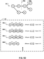
- an example data structure 580 e.g., a directed graph
- the alert correlator 512 can use information provided by the threat intelligence data source 534 and/or other rule or pattern-based sources and/or anomaly detection mechanisms to determine which paths may be of interest, and which paths may be irrelevant.
- an anomaly detection mechanism may observe an unusual occurrence of communication between computing devices (e.g., communication between an external host and a programmable logic controller (PLC)), an unusual rate of events between computing devices in a particular timeframe, or another sort of anomaly.
- Paths including nodes and edges corresponding to one or more anomalous occurrences, for example, may be of interest.
- nodes 482a, 482b, 482c, and 482d can represent computing devices (e.g., servers) within the information technology (IT) network domain 102, the IT DMZ 106a, the operational technology (OT) network domain 104, or the OT DMZ 106b.
- the alert correlator 512 may determine that the nodes 482a, 482b, 482c, and 482d are without relationship edges directed to them, and that the nodes do not represent originating devices (i.e., devices that are identified as originating an attack path).
- the nodes 482a, 482b, 482c, and 482d may be determined as being irrelevant to a path of interest, and the nodes and any edges directed from the nodes that represent relationships to other computing devices represented in the data structure 580 may be pruned by the alert correlator 512.
- the pruned data structure can then be stored for further processing and/or for display to a system operator.
- information related to paths that have previously been identified (e.g., by an operator) as being irrelevant may be used to prune paths from a data structure.
- a path that had previously been determined by the alert correlator 512 as being a potential path of interest may be identified by an operator as being irrelevant (e.g., a false positive).
- the alert correlator 512 determines that a particular path includes characteristics of the path that was identified as being irrelevant (e.g., based on information provided by the threat intelligence data source 534), the particular path may be pruned from the data structure 580.
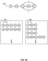
- an example data structure 590 (e.g., a pruned version of the example data structure 580) is shown.
- the alert correlator 512 can use information from the threat intelligence data source 534, for example, to enrich the example data structure 590 to include additional information regarding one or more paths of interest, such as information related to past actions associated with computing devices represented by nodes included in the data structure. For example, if a particular computing device has been reported as being associated with malicious activities, a node representing the computing device may be enriched to include such information.
- the threat scenarios 560 can be provided by the event correlator 512, for example, to the threat analyzer 516 and the visualization generator 518.
- the threat scenarios 560 may be represented by a pruned data structure.
- the data structure 590 e.g., a pruned directed graph, shown in FIG. 5C
- the alert correlator 512 can provide uncorrelated meta-alerts 562 to an event analysis and management system 570 (e.g., a security information and event management (SIEM) system).
- SIEM security information and event management
- an uncorrelated meta-alert may eventually be correlated to other alerts (e.g., after additional event/alert data is collected), and the previously uncorrelated meta-alert may be correlated to generate an additional threat scenario.
- the alert correlator 512 can provide correlated meta-alerts 562 to the event analysis and management system 570.
- the event analysis and management system 570 may support a format to receive correlated and/or uncorrelated meta-alerts.
- the alert correlation and pattern extraction system 502 can use the pattern extractor 514, for example, to detect previously unknown security threats.
- the pattern extractor 514 can analyze data from the targets and attackers data source 530 and from the unsuccessful attacks data source 536 to identify patterns, signatures, and rules associated with potential security attacks.
- data related to potential attacks can be provided to one or more components for use in identifying and/or preventing future attacks.
- data from the pattern extractor 514 can be provided to a risk management component 572 and/or to the threat intelligence data source 534.
- the risk management component 572 may provide information to a user (e.g., a network administrator) to assist in installing new software or software patches within a system, based on identified risks.
- the alert correlation and pattern extraction system 502 can use the threat analyzer 516, for example, to analyze the threat scenarios 560, and to generate data associated with one or more courses of action 574.
- the threat analyzer 516 can determine the impact of attacks on the operation of information technology and operational technology networks (e.g., the information technology network domain 102 and the operational technology network domain 104, shown in FIG. 1 ), rank threat scenarios 560 based on their importance and on system priorities, and provide courses of action 574 relevant to each threat scenario (e.g., based on information provided by the threat intelligence data source 534).
- Processed threat scenario data for example, can be provided by the threat analyzer 516 to the threat intelligence data source 534.
- appropriate courses of action 574 may be provided for each domain (e.g., information technology and operational technology) and/or each device in an industrial control system network.
- Courses of action 574 may include actions such as closing ports on computing devices, blocking communications that originate from particular internet protocol addresses, shutting down computing devices, and so forth.
- the alert correlation and pattern extraction system 502 can use the visualization generator 518, for example, to generate one or more reports and/or diagrams (e.g., diagram 576).
- the visualization generator 518 can analyze the threat scenarios 560 and can determine a progression of system states and communication paths during an attack.
- diagrams generated by the visual generator 518 may include sunburst diagrams, node diagrams, and/or other suitable diagrams, which may illustrate communications patterns between computing devices in a network.
- a visualization may be generated based on a data structure that represents one or more potential paths of interest (e.g., attack paths).
- the data structure 590 e.g., a pruned directed graph, shown in FIG.
- the diagram 576 can be used by the visualization generator 518 to generate the diagram 576.
- the diagram 576 for example, can be presented to an operator by the interface device 154 (shown in FIG. 1 ). Upon reviewing the diagram 576, for example, the operator may identify anomalous network activity and/or may identify one or more irrelevant paths (e.g., false positives, noise, etc.).
- FIG. 6 is a flowchart of an example process 600 that can be executed in accordance with implementations of the present disclosure.
- the process 600 for example, can be performed by systems such as one or more of the example systems described above.
- the example process 600 includes receiving activity data from multiple domains, filtering and verifying the activity data, aggregating the activity data, correlating the activity data, and providing one or more visualizations and courses of action in response to the activity data.
- Activity data can be received from multiple domains (602).
- activity data e.g., event/alert data provided by one or more intrusion detection systems
- event correlation system e.g., activity data can be received from an information technology (IT) and from an operational technology (OT) network.
- IT information technology
- OOT operational technology
- Activity data can be filtered and verified (604).
- information technology (IT) and operational technology (OT) activity data can be filtered, verified, and further processed.
- Filtered activity data can be maintained for further use (e.g., by one or more threat intelligence services).
- Activity data e.g., raw alerts indicative of potential attacks can be provided for aggregation.
- Activity data can be aggregated (606).
- raw alerts from an information technology (IT) and from an operational technology (OT) network can be fused and aggregated.
- Fused and aggregated alerts (i.e., meta-alerts) and raw alerts can be provided for correlation.
- Activity data can be correlated (608).
- meta-alerts and raw alerts can be correlated, based on threat intelligence (e.g., attack signatures and profiles). Further, the meta-alerts and raw alerts can be extracted to identify data associated with targets and attackers. Based on data associated with the targets and attackers and based on previously filtered activity data, for example, patterns can be extracted and the threat intelligence can be updated.
- threat intelligence e.g., attack signatures and profiles
- the meta-alerts and raw alerts can be extracted to identify data associated with targets and attackers. Based on data associated with the targets and attackers and based on previously filtered activity data, for example, patterns can be extracted and the threat intelligence can be updated.
- One or more visualizations and/or courses of action can be provided (610). Referring to FIGS. 2 and 5 and as discussed above, for example, by correlating meta-alerts and raw alerts, one or more threat scenarios may be identified, which can be used for generating visualizations and/or for identifying courses of action. Further, information associated with meta-alerts may be provided to an event analysis and management system.
- Embodiments of the subject matter and the functional operations described in this specification can be implemented in digital electronic circuitry, in tangibly-embodied computer software or firmware, in computer hardware, including the structures disclosed in this specification and their structural equivalents, or in combinations of one or more of them.
- Embodiments of the subject matter described in this specification can be implemented as one or more computer programs, i.e., one or more modules of computer program instructions encoded on a tangible non-transitory program carrier for execution by, or to control the operation of, data processing apparatus.
- the program instructions can be encoded on an artificially-generated propagated signal, e.g., a machine-generated electrical, optical, or electromagnetic signal, that is generated to encode information for transmission to suitable receiver apparatus for execution by a data processing apparatus.
- the computer storage medium can be a machine-readable storage device, a machine-readable storage substrate, a random or serial access memory device, or a combination of one or more of them.
- data processing apparatus refers to data processing hardware and encompasses all kinds of apparatus, devices, and machines for processing data, including by way of example a programmable processor, a computer, or multiple processors or computers.
- the apparatus can also be or further include special purpose logic circuitry, e.g., an FPGA (field programmable gate array) or an ASIC (application-specific integrated circuit).
- the apparatus can optionally include, in addition to hardware, code that creates an execution environment for computer programs, e.g., code that constitutes processor firmware, a protocol stack, a database management system, an operating system, or a combination of one or more of them.
- a computer program which may also be referred to or described as a program, software, a software application, a module, a software module, a script, or code, can be written in any form of programming language, including compiled or interpreted languages, or declarative or procedural languages, and it can be deployed in any form, including as a stand-alone program or as a module, component, subroutine, or other unit suitable for use in a computing environment.
- a computer program may, but need not, correspond to a file in a file system.
- a program can be stored in a portion of a file that holds other programs or data, e.g., one or more scripts stored in a markup language document, in a single file dedicated to the program in question, or in multiple coordinated files, e.g., files that store one or more modules, sub-programs, or portions of code.
- a computer program can be deployed to be executed on one computer or on multiple computers that are located at one site or distributed across multiple sites and interconnected by a communication network.
- the processes and logic flows described in this specification can be performed by one or more programmable computers executing one or more computer programs to perform functions by operating on input data and generating output.
- the processes and logic flows can also be performed by, and apparatus can also be implemented as, special purpose logic circuitry, e.g., an FPGA (field programmable gate array) or an ASIC (application-specific integrated circuit).
- special purpose logic circuitry e.g., an FPGA (field programmable gate array) or an ASIC (application-specific integrated circuit).
- Computers suitable for the execution of a computer program include, by way of example, general or special purpose microprocessors or both, or any other kind of central processing unit.
- a central processing unit will receive instructions and data from a read-only memory or a random access memory or both.
- the essential elements of a computer are a central processing unit for performing or executing instructions and one or more memory devices for storing instructions and data.
- a computer will also include, or be operatively coupled to receive data from or transfer data to, or both, one or more mass storage devices for storing data, e.g., magnetic, magneto-optical disks, or optical disks.
- mass storage devices for storing data, e.g., magnetic, magneto-optical disks, or optical disks.
- a computer need not have such devices.
- a computer can be embedded in another device, e.g., a mobile telephone, a personal digital assistant (PDA), a mobile audio or video player, a game console, a Global Positioning System (GPS) receiver, or a portable storage device, e.g., a universal serial bus (USB) flash drive, to name just a few.
- PDA personal digital assistant
- GPS Global Positioning System
- USB universal serial bus
- Computer-readable media suitable for storing computer program instructions and data include all forms of non-volatile memory, media and memory devices, including by way of example semiconductor memory devices, e.g., EPROM, EEPROM, and flash memory devices; magnetic disks, e.g., internal hard disks or removable disks; magneto-optical disks; and CD-ROM and DVD-ROM disks.
- semiconductor memory devices e.g., EPROM, EEPROM, and flash memory devices
- magnetic disks e.g., internal hard disks or removable disks
- magneto-optical disks e.g., CD-ROM and DVD-ROM disks.
- the processor and the memory can be supplemented by, or incorporated in, special purpose logic circuitry.
- a computer having a display device, e.g., a CRT (cathode ray tube) or LCD (liquid crystal display) monitor, for displaying information to the user and a keyboard and a pointing device, e.g., a mouse or a trackball, by which the user can provide input to the computer.
- a display device e.g., a CRT (cathode ray tube) or LCD (liquid crystal display) monitor
- a keyboard and a pointing device e.g., a mouse or a trackball
- Other kinds of devices can be used to provide for interaction with a user as well; for example, feedback provided to the user can be any form of sensory feedback, e.g., visual feedback, auditory feedback, or tactile feedback; and input from the user can be received in any form, including acoustic, speech, or tactile input.
- a computer can interact with a user by sending documents to and receiving documents from a device that is used by the user; for example, by sending web pages to
- Embodiments of the subject matter described in this specification can be implemented in a computing system that includes a back-end component, e.g., as a data server, or that includes a middleware component, e.g., an application server, or that includes a front-end component, e.g., a client computer having a graphical user interface or a Web browser through which a user can interact with an implementation of the subject matter described in this specification, or any combination of one or more such back-end, middleware, or front-end components.
- the components of the system can be interconnected by any form or medium of digital data communication, e.g., a communication network. Examples of communication networks include a local area network (LAN) and a wide area network (WAN), e.g., the Internet.
- LAN local area network
- WAN wide area network
- the computing system can include clients and servers.
- a client and server are generally remote from each other and typically interact through a communication network. The relationship of client and server arises by virtue of computer programs running on the respective computers and having a client-server relationship to each other.
- a server transmits data, e.g., an HTML page, to a user device, e.g., for purposes of displaying data to and receiving user input from a user interacting with the user device, which acts as a client.
- Data generated at the user device e.g., a result of the user interaction, can be received from the user device at the server.
- FIG. 7 shows a schematic diagram of a generic computer system 700.
- the system 700 can be used for the operations described in association with any of the computer-implement methods described previously, according to one implementation.
- the system 700 includes a processor 710, a memory 720, a storage device 730, and an input/output device 740. Each of the components 710, 720, 730, and 740 are interconnected using a system bus 750.
- the processor 710 is capable of processing instructions for execution within the system 700. In one implementation, the processor 710 is a single-threaded processor. In another implementation, the processor 710 is a multi-threaded processor.
- the processor 710 is capable of processing instructions stored in the memory 720 or on the storage device 730 to display graphical information for a user interface on the input/output device 740.
- the memory 720 stores information within the system 700.
- the memory 720 is a computer-readable medium.
- the memory 720 is a volatile memory unit.
- the memory 720 is a non-volatile memory unit.
- the storage device 730 is capable of providing mass storage for the system 700.
- the storage device 730 is a computer-readable medium.
- the storage device 730 may be a floppy disk device, a hard disk device, an optical disk device, or a tape device.
- the input/output device 740 provides input/output operations for the system 700.
- the input/output device 740 includes a keyboard and/or pointing device.
- the input/output device 740 includes a display unit for displaying graphical user interfaces.
Description
- This application claims the benefit of
U.S. Provisional Application No. 62/145,248, filed April 9, 2015 - The present disclosure relates to security and network operations.
- In general, one innovative aspect of the subject matter described in this specification can be embodied in methods for correlating domain activity, including receiving first domain activity data from a first network domain and second domain activity data from a second network domain, the first domain activity data and the second domain activity data including events, alerts, or both from the respective first and second network domains, filtering the first domain activity data and the second domain activity data to remove irrelevant activity data, based on a first set of profile data for devices in the first network domain and a second set of profile data for devices in the second network domain, aggregating unfiltered first domain activity data and unfiltered second domain activity data, correlating aggregated unfiltered first domain activity data and unfiltered second domain activity data to determine an attack path for an attack that occurs across the first network domain and the second network domain, based on attack signatures and profiles associated with previously identified attacks, and generating a visualization of the attack path.
- Other embodiments of this aspect include corresponding computer methods, and include corresponding apparatus and computer programs recorded on one or more computer storage devices, each configured to perform the actions of the methods. A system of one or more computers can be configured to perform particular operations or actions by virtue of having software, firmware, hardware, or a combination of them installed on the system that in operation causes or cause the system to perform the actions. One or more computer programs can be configured to perform particular operations or actions by virtue of including instructions that, when executed by data processing apparatus, cause the apparatus to perform the actions.
- These and other embodiments may each optionally include one or more of the following features. For instance, the first domain activity data, the second domain activity data, or both, can include log data provided by one or more security sensors. The first network domain can be an information technology network domain and the second network domain can be an operational technology network domain. The filtering can include determining, for each event or alert, a corresponding attack and a corresponding target, determining, based on profile data for the corresponding target, that the attack on the target is rendered unsuccessful, and filtering the corresponding event or alert. The filtering can include, for each unfiltered event or alert, dynamically retrieving current status information about the corresponding target, determining, based the current status information about the corresponding target, that the attack on the target is rendered unsuccessful, and filtering the corresponding event or alert.
- Particular embodiments of the subject matter described in this specification may be implemented so as to realize one or more of the following advantages. A single vantage point and a standardized data exchange format may be provided for analyzing event/alert log data from information technology (IT) and operational technology (OT) networks. Currently available security sensors (e.g., intrusion detection systems (IDS), intrusion prevention systems (IPS), and other suitable security sensors) may be leveraged, resulting in architectural independence, flexibility, and compatibility with legacy infrastructures/networks. False alarm rates may be reduced in an event detection process. Multi-step, multi-domain threat scenarios may be detected and/or constructed. Complex scenarios may be visually represented, and network status may be shown at each step of an attack. Threat intelligence platforms/services may be integrated to further enrich and contextualize information and constructed scenarios.
- The details of one or more implementations of the subject matter described in this specification are set forth in the accompanying drawings and the description below. Other potential features, aspects, and advantages of the subject matter will become apparent from the description, the drawings, and the claims.
-
-
FIGS. 1 - 3 depict example systems that can execute implementations of the present disclosure. -
FIG. 4A depicts an example system that can execute implementations of the present disclosure. -
FIG. 4B depicts an example data structure that can be used by implementations of the present disclosure. -
FIG. 5A depicts an example system that can execute implementations of the present disclosure. -
FIG. 5B and5C depict example data structures that can be used by implementations of the present disclosure. -
FIG. 6 is a flowchart of an example process that can be executed in accordance with implementations of the present disclosure. -
FIG. 7 is a block diagram of a computing system that can be used in connection with computer-implemented methods described in this document. - Like reference symbols in the various drawings indicate like elements.
- This specification describes systems, methods, and computer programs for performing event correlation across heterogeneous operations. For example, an industrial internet may be used to manage and administer industrial control systems (ICS), which may communicate over an enterprise network and may include information technology (IT) and operational technology (OT) domains. Some threat scenarios may include multi-step, multi-domain attacks, and may include attacks that originate in one domain, and proceed to another domain. By filtering, aggregating, and correlating data from event/alert logs from each domain (e.g., IT and OT domains), for example, complex attack patterns may be detected. Information about the attack patterns (e.g., visualization data) may be reported to a security analyst, and may be used for implementing appropriate courses of action.
-
FIG. 1 depicts anexample system 100 that can execute implementations of the present disclosure. In the present example, the system 100 (e.g., an industrial control system) includes multiple network domains, including an information technology (IT) network domain 102 (e.g., including an enterprise network) and an operational technology (OT) network domain 104. The informationtechnology network domain 102 and the operational technology network domain 104 can be in communication, for example, over a demilitarized zone (DMZ) 106a of the informationtechnology network domain 102 and a demilitarized zone (DMZ) 106b of the operational technology network domain 104. Each of thenetwork domains 102 and 104, for example, may include local and wide area networks (LAN/WAN) and wireless networks, and can be used to integrate various computing devices, such as servers, mainframes, desktops, laptops, tablets, smartphones, and industrial control devices and sensors, that may run on multiple different operating systems and may employ multiple different communication protocols. - The information
technology network domain 102 can include various computing devices (e.g., computing server 112), input/output devices (e.g., interface device 114), and/or subsystems. Thecomputing server 112, for example, can include one or more processors configured to execute instructions stored by computer-readable media for performing various operations, such as input/output, communication, data processing, and/or data maintenance. To interact with the computing server, for example, a user can employ the interface device 114 (e.g., including one or more presentation components, such as a display, and one or more input components such as a keyboard, mouse, and/or touchpad). - The operational technology network domain 104 can include various computing devices, input/output devices, and/or subsystems. In the present example, the operational technology network domain 104 includes a
supervisory system 120, ahistorian server 122, anapplication server 124, one or more human-machine interface (HMI) devices (e.g., HMI device 126), and one or more controller devices (e.g., controller device 128) and sensor devices (e.g., sensor device 130). Thesupervisory system 120, for example, can coordinate one or more low-level controls and/or low-level sensors. In the present example, thesupervisory system 120 can provide data to and receive data from thecontroller device 128 and thesensor device 130. Thehistorian server 122, for example, can store, maintain, and provide information related to activities performed by each controller device and sensor data provided by each sensor device in the operational technology network domain 104. Theapplication server 124, for example, can host applications that may operate within the operational technology network domain 104. - In some implementations, the
system 100 may include one or more security sensors (e.g.,security sensors system 100 may include network based (NIDS) and host based (HIDS) intrusion detection systems, intrusion prevention systems (IPS), anti-virus systems, firewalls, and other detection/logging services (e.g., web server logs, database logs, etc.) which can monitor communications activity to and from computing devices included in the industrial technology (IT)network domain 102, theIT DMZ 106a, the operational technology (OT) network domain 104, and/or theOT DMZ 106b, and can monitor system activity associated with the devices. Data associated with potentially malicious activity may be detected (and optionally, recorded) by thesecurity sensors system 100, and/or may be provided to other components of thesystem 100. For example,activity data corresponding security sensors event correlation system 150. Such activity data may also be provided to anevent correlation system 150 by a Security Information and Event Management (SIEM) system. Theactivity data 140a, for example, may include enterprise data from the informationtechnology network domain 102, provided by host-based monitoring systems (e.g., intrusion detection/prevention systems, web server logging services, system logs, etc.) and/or network-based monitoring systems (e.g., intrusion detection/prevention systems, firewalls, routers, etc.). Theactivity data 140b, for example, may include data associated with communication over theIT DMZ 106a. Theactivity data 140c, for example, may include data associated with communication over the OTDMZ 106b. Theactivity data 140d, for example, may include supervisory data, control layer data, and/or sensor and controller device data from the operational technology network domain 104, provided by host-based monitoring systems and/or network-based monitoring systems. - In the present example, each of the
activity data security sensors - The
event correlation system 150, for example, can receive theactivity data network domain 102, theIT DMZ 106a, the operational technology (OT) network domain 104, and theOT DMZ 106b), and can standardize, filter, aggregate, and correlate the data to detect anomalies and potentially malicious activity associated with multi-stage, multi-domain attacks. In the present example, theevent correlation system 150 can include various computing devices (e.g., computing server 152), input/output devices (e.g., interface device 154), and/or subsystems. Thecomputing server 152, for example, can include one or more processors configured to execute instructions stored by computer-readable media for performing various operations, such as input/output, communication, data processing, and/or data maintenance. To interact with the computing server, for example, a user can employ the interface device 154 (e.g., including one or more presentation components, such as a display, and one or more input components such as a keyboard, mouse, and/or touchpad). - In some implementations, output may be provided by the
event correlation system 150 to another system (e.g., a security information and event management (SIEM) system) and/or to a system operator as reporting/visualization data. Based on the system output, for example, appropriate courses of action may be employed to counter ongoing and/or future attacks. In the present example, the information technology (IT)network domain 102, theIT DMZ 106a, the operational technology (OT) network domain 104, and theOT DMZ 106b each has different characteristics (e.g., architecture, resources, protocols, and standards), and each domain may be susceptible to different security threats. Occasionally, correlations may not be detected among events/alerts within a single domain, (and if correlations are detected, an extent of an associated compromise may not be entirely known), but correlations may be detected among events/alerts across multiple domains. By correlating data from multiple domains, for example, complex attacks (e.g., multi-stage, multi-domain attacks executed over time) may be detected, and a single vantage point may be provided to security technicians. -
FIG. 2 depicts anexample system 200 that can execute implementations of the present disclosure. In the present example, thesystem 200 includes an event correlation system 202 (e.g., similar to theevent correlation system 150, shown inFIG. 1 ). Theevent correlation system 202, for example, can include various hardware and/or software-based components (e.g., software modules, objects, engines, libraries, etc.) including an information technology (IT) activity data filter 210, an operational technology (OT) activity data filter 212, anaggregator 214, acorrelator 216, apattern recognizer 218, aresponse generator 220, and an operator input/output (I/O)component 222. Various data sources (e.g., databases, file systems, etc.) may maintain data used by thesystem 200 and its components. In the present example, thesystem 200 can receive information from an information technology (IT)network data source 230, an operational technology (OT)network data source 232, and a threatintelligence data source 234. Activity data associated with a demilitarized zone (DMZ) or peripheral network, for example, may be provided by the information technologynetwork data source 230 and/or the operational technologynetwork data source 232. In general, thesystem 200 and its various components (e.g.,components - In the present example, the
event correlation system 202 can receive information technology (IT)activity data 240 that includes event/alert data from an information technology network (e.g., the information technology (IT)network domain 102, and optionally theIT DMZ 106a, shown inFIG. 1 ), and can receive operational technology (OT)activity data 242 that includes event/alert data from an operational technology network (e.g., the operational technology (OT) network domain 104, and optionally theOT DMZ 106b, shown inFIG. 1 ). In some implementations, the informationtechnology activity data 240 and/or the operationaltechnology activity data 242 may include log data provided by one or more security sensors (e.g., thesecurity sensors FIG. 1 ). Upon receiving the informationtechnology activity data 240, for example, theevent correlation system 202 can use the information technology activity data filter 210 to filter out irrelevant (or "false") events/alerts, based on data provided by the information technologynetwork data source 230. Similarly, upon receiving the operationaltechnology activity data 242, for example, theevent correlation system 202 can use the operational technology activity data filter 212 to filter out irrelevant (or "false") events/alerts, based on data provided by the operational technologynetwork data source 232. Operation of the information technology activity data filter 210 and the operational technology activity data filter 212 is discussed in further detail below in association withFIG. 3 . - After filtering the information
technology activity data 240 and the operationaltechnology activity data 242, for example, filtered event/alert data can be provided by the information technology activity data filter 210 and the operational technology activity data filter 212 to theaggregator 214. In general, theevent correlation system 202 can use theaggregator 214 to remove duplicate and/or redundant events/alerts, to combine events/alerts related to the same attack, and to combine events/alerts relating to different attacks but possessing similar characteristics, thus reducing the number of events/alerts under consideration. In some implementations, theaggregator 214 may reference data provided by the information technologynetwork data source 230 and/or the operational technologynetwork data source 232 when performing aggregation operations. Operation of theaggregator 214 is discussed in further detail below in association withFIG. 4A . - After aggregating the event/alert data, for example, aggregated data can be provided by the
aggregator 214 to thecorrelator 216. In general, theevent correlation system 202 can use thecorrelator 216 to generate a chain of events/alerts that may correspond to a threat scenario, and theevent correlation system 202 can use the pattern recognizer 218 (e.g., based on data provide by the threat intelligence data source 234) to identify attack patterns associated with the threat scenario, and to further describe and/or enrich threat scenario information. Based on threat scenarios identified by thecorrelator 216 and attack patterns identified by thepattern recognizer 218, and optionally based on operator input received by the operator input/output component 222, for example, theresponse generator 220 can provide appropriate courses of action for responding to threats to theinformation technology network 250 and theoperational technology network 252. Operation of thecorrelator 216 and thepattern recognizer 218 is discussed in further detail below in association withFIG. 5A . -
FIG. 3 depicts anexample system 300 that can execute implementations of the present disclosure. In the present example, thesystem 300 includes a filtering and verification system 302 (e.g., corresponding to the information technology activity data filter 210 and the operational technology activity data filter 212, shown inFIG. 2 ). The filtering andverification system 302, for example, can include various hardware and/or software-based components (e.g., software modules, objects, engines, libraries, etc.) including a rule-basedfilter 310 for information technology (IT) activity data, a rule-basedfilter 312 for operational technology (OT) activity data, anoptional verifier 320 for information technology (IT) activity data, and anoptional verifier 322 for operational technology (OT) activity data. Various data sources (e.g., databases, file systems, etc.) may maintain data used by thesystem 300 and its components. In the present example, thesystem 300 includes an information technology (IT) network data source 330 (e.g., including configuration management information associated with devices in the information technology (IT)network domain 102, shown inFIG. 1 ), an operational technology (OT) network data source 332 (e.g., including configuration management information associated with devices in the operational technology (OT) network domain 104, shown inFIG. 1 ), and a filteredalerts data source 336. In general, thesystem 300 and its various components (e.g.,components - In the present example, the filtering and
verification system 302 can receive information technology (IT)activity data 340 that includes event/alert data from an information technology network, and optionally, a corresponding DMZ (e.g., the information technology (IT)network domain 102 and theIT DMZ 106a, shown inFIG. 1 ), and can receive operational technology (OT)activity data 342 that includes event/alert data from an operational technology network, and optionally, a corresponding DMZ (e.g., the operational technology (OT) network domain 104 and theDMZ 106b, shown inFIG. 1 ). In some implementations, the informationtechnology activity data 340 and/or the operationaltechnology activity data 342 may include log data provided by one or more security sensors (e.g.,security sensors FIG. 1 ). For example, activity data received from multiple sources (e.g., multiple security sensors, intrusion detection systems, and/or other security tools) may be heterogeneous in regard to language, protocols, and standards. Such activity data may be heterogeneous, for example, not only because of different security tools in a single domain (which may be resolved through the use of alert/event standardization/normalization tools that convert data to a standard format), but because of different protocol standards which may be employed in multiple different domains by the same security tool. As another example, a standard format may be used for communicating activity data. Upon receiving the informationtechnology activity data 340, for example, the filtering andverification system 302 can use the rule-basedfilter 310 for information technology activity data to filter out irrelevant (or "false") events/alerts, based on data provided by the information technology network data source 330 (e.g., similar to the information technologynetwork data source 230, shown inFIG. 2 ), and in conjunction with additional rules that may be defined by system administrators. Similarly, upon receiving the operationaltechnology activity data 342, for example, the filtering andverification system 302 can use the rule-basedfilter 312 for operational technology activity data to filter out irrelevant (or "false") events/alerts, based on data provided by the operational technology network database 332 (e.g., similar to the operational technologynetwork data source 232, shown inFIG. 2 ), and in conjunction with additional rules that may be defined by system administrators. - In general, rule-based filtering performed by each of the rule-based
filters FIG. 1 ) can be maintained by the information technologynetwork data source 330, and profile data for potential targets (e.g., computing devices, controllers, and sensors) in the operational technology network domain 104 (shown inFIG. 1 ) can be maintained by the operational technologynetwork data source 332. For each received event/alert, for example, an appropriate rule-based filter may reference profile data from an appropriate network data source for a target that corresponds to the event/alert (e.g., based on device address), and can determine whether the received event/alert indicates a potential attack. For example, a network-based intrusion detection system may not have specific information about an attacker or about a target, but may generate an alert based on the contents of a communications packet - that is, the alert may be generated if the packet includes an exploit directed to a known vulnerability. However, the generated alert in the present example may or may not indicate a successful attack on the target. For example, if an attack relies on certain system attributes (e.g., a type of operating system), but the system has different attributes (e.g., a different operating system) that are not affected by an attempted attack, the attack is rendered unsuccessful. As another example, if a communications packet is directed to a computing device that does not exist on a network, the network drops the communications packet, rendering the packet ineffective and the attack unsuccessful. By filtering events/alerts associated with attack attempts that are likely to be unsuccessful, reconnaissance attempts (intentional or unintentional), and/or internal activity known to be benign, for example, the number of events/alerts under consideration may be reduced, thus reducing the amount of processing in subsequent stages. - In some implementations, profile data and/or statuses of potential targets (e.g., computing devices) may be dynamically determined when filtering received events/alerts. For example, after performing rule-based filtering on the information
technology activity data 340, the filtering andverification system 302 can optionally use theverifier 320 to dynamically verify profile data for a target on the information technology network domain 102 (shown inFIG. 1 ), and the filtering andverification system 302 can optionally use theverifier 322 to dynamically verify profile data for a target on the operational technology network domain 104 (shown inFIG. 1 ). For each received event/alert that has not been previously filtered, for example, an appropriate verifier can determine whether dynamically retrieved information regarding a target corresponding to the event/alert (e.g., based on device address) indicates that the event/alert is associated with actual malicious activity. For example, for an unfiltered event/alert corresponding to a target on the informationtechnology network domain 102, theverifier 320 can communicate with a system/network scanner 350 (e.g., with access to configuration management information) to receive current information about the target. In the present example, a communications packet may be directed to an open port on the target, and the rule-basedfilter 310 may not filter the corresponding alert. However, based on information provided by the system/network scanner 350, theverifier 320 may determine that the target has been patched to counter an attack associated with the alert, for example, rendering the communications packet ineffective and the attack unsuccessful. In the present example, the alert may be filtered out and/or labeled as a potentially unsuccessful attack. As another example, for an unfiltered event/alert corresponding to a target on the operational technology network domain 104, theverifier 322 can communicate with adevice virtualization component 352 to receive current information about the target. In the present example, a communications packet may be directed to changing a setting (e.g., a temperature setting, an on/off setting, a power level, a position, etc.) on the target (e.g., a controller device). Thedevice virtualization component 352, for example, can query the target (or one or more sensors associated with the target) for its status to determine an effect of the communications packet. A negative effect, for example, may indicate a potentially successful attack, whereas a neutral effect or lack of an effect may indicate a potentially unsuccessful attack. - After performing rule-based filtering and verification, for example, the filtering and
verification system 302 can record filtered alert data associated with potentially unsuccessful attacks and/or false positives (e.g., in the filtered alerts data source 336), and can provide data associated with potential attacks for further processing. For example, thealerts 360 may be indicative of potential attacks on an information technology network (e.g., the informationtechnology network domain 102, shown inFIG. 1 ) and thealerts 362 may be indicative of potential attacks on an operational technology network (e.g., the operational technology network domain 104, shown inFIG. 1 ). Data maintained by the filteredalerts data source 336, for example, may be used for generating future security policies, as is discussed in further detail below in association withFIG. 5A . -
FIG. 4A depicts anexample system 400 that can execute implementations of the present disclosure. In the present example, thesystem 400 includes an alert aggregation system 402 (e.g., corresponding to theaggregator 214, shown inFIG. 2 ). Thealert aggregation system 402, for example, can include various hardware and/or software-based components (e.g., software modules, objections, engines, libraries, etc.) including analert fuser 410 and analert aggregator 412. In general, thesystem 400 and its various components (e.g.,components 410 and 412) can perform functions for processing and aggregating event/alert data received from various different sources. By aggregating event/alert data, for example, data redundancy can be decreased, and the aggregated event/alert data may be further processed to identify trends and correlations in the data. - In the present example, the
aggregation system 402 can receivealert data 420 corresponding to potential attacks on an information technology network (e.g., the informationtechnology network domain 102, shown inFIG. 1 ) andalert data 422 corresponding to potential attacks on an operational technology network (e.g., the operational technology network domain 104, shown inFIG. 1 ). Upon receiving thealert data 420 and thealert data 422, for example, theaggregation system 402 can use thefuser 410 to combine similar alerts, which may have been generated by different intrusion detection systems, security tools and/or sensors. For example, if multiple intrusion detection systems are included in thesystem 100, a malicious packet may be detected by each of the intrusion detection systems, and each of the systems may generate a similar alert in response to detecting the packet. In the present example, each of the similar alerts may include similar data, yet may have slightly different timestamps (e.g., due to network traffic speeds). If thefuser 410 determines that multiple alerts are related (e.g., the alerts were generated in response to the same packet or event based on having similar data and having timestamps within a threshold similarity value), for example, the multiple alerts may be combined into a meta-alert. Thefuser 410 can provide meta-alerts 430 and raw alerts 432 (i.e., uncombined alerts) to thealert aggregator 412. - Upon receiving the meta-
alerts 430 andraw alerts 432 from thealert fuser 410, for example, thealert aggregator 412 can aggregate the sets ofalerts - In some implementations, each of the sets of
alerts alert aggregator 412 determines that two or more of the meta-alerts 430 and/or theraw alerts 432 are similar based on criteria that pertains to data included in each alert (e.g., two or more alerts have the same destination address (and optionally, port number) and have timestamps within a threshold similarity value, two or more alerts have the same source address and have timestamps within a threshold similarity value, two or more alerts are targeted to similar services, or another suitable criteria based on similarity of alert attributes), for example, thealert aggregator 412 may aggregate the alerts. While the description above with regard to two or more of the meta-alerts 430 orraw alerts 432 being similar based on criteria that pertains to data included in each alert (and then being aggregated), it should be understood that thealert aggregator 412 may determine that a large or very large number of alerts are related (e.g. hundreds, thousands, or more alerts) and aggregate those alerts into a single record or data structure that facilitates efficient processing of a large volume of alert data. Thealert aggregation system 402 can provide aggregatedalerts 440 andnon-aggregated alerts 442 as a combined set of meta andraw alerts 450 for further processing. Thealert aggregation system 402 can also generate and store a data structure that represents both aggregated alerts and a relationship between different aggregated alerts, for example, based on a source and destination address in the aggregated alert. Once generated and stored, the data structure (described in greater detail below) can be further processed by the system, such asevent correlation system 150 andsystem 500. In some implementations, the aggregatedalerts 440 can be provided by thealert aggregation system 402 to an event analysis andmanagement system 460 for further analysis. -
FIG. 4B depicts anexample data structure 480 that can be used by implementations of the present disclosure once it is generated and stored by thealert aggregation system 402. In some implementations, the data structure 480 (e.g., a directed graph) can be generated and used to represent the meta andraw alerts 450 provided by thealert aggregation system 402. Nodes (e.g.,node 482, node 484) in thedata structure 480 can represent entities referenced in the meta andraw alerts 450, such as computing devices/assets (e.g., devices/assets within the information technology (IT)network domain 102, theIT DMZ 106a, the operational technology (OT) network domain 104, and theOT DMZ 106b), internet protocol (IP) addresses, and ports. Edges (e.g., edge 486) in thedata structure 480 can represent relationships between the entities (e.g., an aggregated event occurring between two entities). For example, theedge 486 can represent a communication event (e.g., including a timestamp) between an originating computing device (e.g., a server) represented by thenode 482 and a destination computing device (e.g., a DMZ server) represented by thenode 484, and can be directed from thenode 482 to thenode 484. When representing computing devices and assets, addresses, and ports with unique nodes in a directed graph, for example, replication of entities may be avoided. When representing relationships between entities as edges in a directed graph, for example, multiple related alerts (e.g., alerts that include similar timestamp data and/or related message data) can be represented by a single edge between two nodes. For example, a particular computing device may attempt a series of port scans on each of a set of other devices. In the present example, the particular computing device (i.e., an origin) and each of the set of other devices (i.e., destinations) can be represented by nodes, and the port scans on each of the set of other devices can be consolidated and represented by a respective edge (e.g., an aggregated event or meta alert) between the particular computing device and each of the other devices. - In some implementations, when aggregating alert data and representing the alert data in a data structure, an edge that represents a relationship between two entities may be annotated with information that indicates a range of values included in a set of alerts that correspond to the edge. For example, if an originating device performs a series of port scans on a destination device over the course of a period of time, a single edge between a node representing the originating device and a node representing the destination device can be annotated with a value indicating a time of a first port scan during the period of time, a value indicating a time of a last port scan during the period of time, and a count of a total number of port scans during the period of time. As another example, if an originating device scans a range of ports on a destination device, a single edge between a node representing the originating device and a node representing the destination device can be appended with values indicating each of the ports scanned.
-
FIG. 5A depicts anexample system 500 that can execute implementations of the present disclosure. In the present example, thesystem 500 includes an alert correlation and pattern extraction system 502 (e.g., corresponding to thecorrelator 216 and thepattern recognizer 218, shown inFIG. 2 ). The alert correlation andpattern extraction system 502 can include various hardware and/or software-based components (e.g., software modules, objects, engines, libraries, etc.) including analert extractor 510, analert correlator 512, apattern extractor 514, athreat analyzer 516, and avisualization generator 518. Various data sources (e.g., databases, file systems, etc.) may maintain data used by thesystem 500 and its components. In the present example, thesystem 500 includes a targets andattackers data source 530, a threat intelligence data source 534 (e.g., similar to the threatintelligence data source 234, shown inFIG. 2 ), and an unsuccessful attacks data source 536 (e.g., including data provided by the filteredalerts data source 336, shown inFIG. 3 ). In general, thesystem 500 and its various components (e.g.,components - In the present example, the correlation and
pattern extraction system 502 can receive meta and raw alerts 550 (e.g., similar to the meta andraw alerts 450, shown inFIG. 4A ) from the alert aggregation system 402 (shown inFIG. 4A ). The meta andraw alerts 550, for example, may include aggregated and non-aggregated alerts that are associated with suspicious network activity from multiple different network domains (e.g., the industrial technology (IT)network domain 102, theIT DMZ 106a, the operational technology (OT) network domain 104, and theOT DMZ 106b, shown inFIG. 1 ). In some implementations, the meta and raw alerts may 550 may be represented by a data structure (e.g., thedata structure 480, shown inFIG. 4B ). Upon receiving the meta andraw alerts 550, for example, the correlation andpattern extraction system 502 can provide alert data to thealert extractor 510 and to thealert correlator 512. Thealert extractor 510, for example, can analyze the meta andraw alerts 550, can extract information from the meta and raw alerts, and can generate a list of computing devices that are targets of attacks, along with data corresponding to attackers of the targets, such as internet protocol (IP) addresses of the attackers. In some implementations, thealert extractor 510 can traverse the data structure 480 (e.g., a directed graph) and mine the data structure for internet protocol (IP) addresses, uniform resource locator (URL) information, and other relevant data. Data associated with targets and attackers can be provided by thealert extractor 510 to the targets andattackers data source 530, for example. Thealert correlator 512, for example, can generate one or more threat scenarios 560 (e.g., chains of events/alerts that indicate attack paths), based on data (e.g., attack signatures and profiles) provided by the threatintelligence data source 534. - In general, correlating alert data may include enriching (e.g., labeling) the alert data, linking related alerts, and identifying an attack path indicated by the linked alerts. For example, the
alert correlator 512 can generatethreat scenarios 560 by determining chains of alerts included in the meta andraw alerts 550, and optionally prioritizing, labeling, or otherwise enriching alert data, based on data provided by the threatintelligence data source 534. Attack signatures and profiles within the threatintelligence data source 534, for example, may relate to communication patterns between computing devices, and may include information related to potential target devices for a type of attack. As new attacks are detected, for example, information related to attack signatures and profiles may be added to the threatintelligence data source 534. - Enriching alert data, for example, may include analyzing alert data (e.g., the meta and raw alerts 550) and identifying alerts that are associated with a particular attacker. For example, a multi-stage attack performed by an attacker may include reconnaissance, delivery, and installation stages. Each stage, for example, may include communication between the attacker and one or more computing devices on a network during one or more sessions. When enriching the meta and
raw alerts 550, for example, thealert correlator 512 can use information provided by the targets andattackers data source 530, the threatintelligence data source 534, and/or additional threat intelligence services to identify alerts that are associated with communications from the particular attacker (e.g., indicated by Internet Protocol (IP) address and country of origin information), and can label or otherwise enrich information related to the alerts as being potentially related to a multi-stage attack. - Linking alert data, for example, may include analyzing previously enriched (e.g., labeled) alerts/events. For example, a subset of the meta and
raw alerts 550 may be labeled as being related to an attack performed by a previously identified attacker. The subset of alerts, for example, may correspond to communication with the attacker and with subsequent alerts that may result from the communication (e.g., after the delivery of a malicious payload). In some implementations, a time-based threshold may be used to determine whether two or more alerts are to be linked. For example, thealert correlator 512 may link two or more similarly labeled alerts if the alerts have timestamps within a suitable time threshold value (e.g., one minute, five minutes, ten minutes, or another suitable value). The time threshold value, for example, may be a configurable tuning parameter. In some implementations, linking alert data (i.e., determining a chain of alerts) may depend on a type of attack indicated by an attack signature and/or profile, or another sort of indicator (e.g., an address of an attacker and/or target). For example, a different sub-function may be used by thealert correlator 512 for determining a chain of alerts for each different type of attack, based on attack signatures and profiles defined by the threatintelligence data source 534. - Identifying an attack path indicated by the linked alerts, for example, may include identifying steps that an attacker takes toward an intended target. The
alert correlator 512, for example, can analyze previously linked alerts to identify an attack path that may cross one or more network domains. In general, identifying an attack path may include determining a series of communications between computing devices. For example, an attacker may attempt to change the status of a controller device in an operational technology (OT) network, but lack physical access. In the present example, to gain access to the controller device, the attacker may launch an attack against a computer device in an information technology (IT) network, and may exploit the computer device in order to step to a human-machine interface (HMI) device in the operational technology network, and then may further exploit the human-machine interface device in order to step to the controller device. Information associated with identified attack paths can be used by thealert correlator 512, to determine one ormore threat scenarios 560. - In some implementations, correlating alert data may include traversing a data structure and determining whether paths included in the data structure are of interest (e.g., represent an attack) or are irrelevant (e.g., represent false positives, noise, etc.). Referring to
FIG. 5B , for example, an example data structure 580 (e.g., a directed graph) is shown. Thealert correlator 512, for example, can use information provided by the threatintelligence data source 534 and/or other rule or pattern-based sources and/or anomaly detection mechanisms to determine which paths may be of interest, and which paths may be irrelevant. As another example, an anomaly detection mechanism may observe an unusual occurrence of communication between computing devices (e.g., communication between an external host and a programmable logic controller (PLC)), an unusual rate of events between computing devices in a particular timeframe, or another sort of anomaly. Paths including nodes and edges corresponding to one or more anomalous occurrences, for example, may be of interest. - In some implementations, paths that are determined to be irrelevant may be pruned from a data structure. In the present example,
nodes network domain 102, theIT DMZ 106a, the operational technology (OT) network domain 104, or theOT DMZ 106b. Thealert correlator 512, for example, may determine that thenodes nodes data structure 580 may be pruned by thealert correlator 512. The pruned data structure can then be stored for further processing and/or for display to a system operator. - In some implementations, information related to paths that have previously been identified (e.g., by an operator) as being irrelevant may be used to prune paths from a data structure. For example, a path that had previously been determined by the
alert correlator 512 as being a potential path of interest may be identified by an operator as being irrelevant (e.g., a false positive). In the present example, if thealert correlator 512 determines that a particular path includes characteristics of the path that was identified as being irrelevant (e.g., based on information provided by the threat intelligence data source 534), the particular path may be pruned from thedata structure 580. - Referring to
FIG. 5C , for example, an example data structure 590 (e.g., a pruned version of the example data structure 580) is shown. Thealert correlator 512 can use information from the threatintelligence data source 534, for example, to enrich theexample data structure 590 to include additional information regarding one or more paths of interest, such as information related to past actions associated with computing devices represented by nodes included in the data structure. For example, if a particular computing device has been reported as being associated with malicious activities, a node representing the computing device may be enriched to include such information. - Referring again to
FIG. 5A , thethreat scenarios 560 can be provided by theevent correlator 512, for example, to thethreat analyzer 516 and thevisualization generator 518. In some implementations, thethreat scenarios 560 may be represented by a pruned data structure. For example, the data structure 590 (e.g., a pruned directed graph, shown inFIG. 5C ) may include various paths of interest (i.e., potential attack paths), enriched with additional information. In some implementations, thealert correlator 512 can provide uncorrelated meta-alerts 562 to an event analysis and management system 570 (e.g., a security information and event management (SIEM) system). For example, an uncorrelated meta-alert may eventually be correlated to other alerts (e.g., after additional event/alert data is collected), and the previously uncorrelated meta-alert may be correlated to generate an additional threat scenario. In some implementations, thealert correlator 512 can provide correlated meta-alerts 562 to the event analysis andmanagement system 570. For example, the event analysis andmanagement system 570 may support a format to receive correlated and/or uncorrelated meta-alerts. - The alert correlation and
pattern extraction system 502 can use thepattern extractor 514, for example, to detect previously unknown security threats. For example, thepattern extractor 514 can analyze data from the targets andattackers data source 530 and from the unsuccessfulattacks data source 536 to identify patterns, signatures, and rules associated with potential security attacks. In some implementations, data related to potential attacks can be provided to one or more components for use in identifying and/or preventing future attacks. In the present example, data from thepattern extractor 514 can be provided to arisk management component 572 and/or to the threatintelligence data source 534. In general, therisk management component 572 may provide information to a user (e.g., a network administrator) to assist in installing new software or software patches within a system, based on identified risks. - The alert correlation and
pattern extraction system 502 can use thethreat analyzer 516, for example, to analyze thethreat scenarios 560, and to generate data associated with one or more courses ofaction 574. For example, thethreat analyzer 516 can determine the impact of attacks on the operation of information technology and operational technology networks (e.g., the informationtechnology network domain 102 and the operational technology network domain 104, shown inFIG. 1 ),rank threat scenarios 560 based on their importance and on system priorities, and provide courses ofaction 574 relevant to each threat scenario (e.g., based on information provided by the threat intelligence data source 534). Processed threat scenario data, for example, can be provided by thethreat analyzer 516 to the threatintelligence data source 534. In some implementations, appropriate courses ofaction 574 may be provided for each domain (e.g., information technology and operational technology) and/or each device in an industrial control system network. Courses ofaction 574, for example, may include actions such as closing ports on computing devices, blocking communications that originate from particular internet protocol addresses, shutting down computing devices, and so forth. - The alert correlation and
pattern extraction system 502 can use thevisualization generator 518, for example, to generate one or more reports and/or diagrams (e.g., diagram 576). For example, thevisualization generator 518 can analyze thethreat scenarios 560 and can determine a progression of system states and communication paths during an attack. In general, diagrams generated by thevisual generator 518 may include sunburst diagrams, node diagrams, and/or other suitable diagrams, which may illustrate communications patterns between computing devices in a network. In some implementations, a visualization may be generated based on a data structure that represents one or more potential paths of interest (e.g., attack paths). For example, the data structure 590 (e.g., a pruned directed graph, shown inFIG. 5C ) can be used by thevisualization generator 518 to generate the diagram 576. The diagram 576, for example, can be presented to an operator by the interface device 154 (shown inFIG. 1 ). Upon reviewing the diagram 576, for example, the operator may identify anomalous network activity and/or may identify one or more irrelevant paths (e.g., false positives, noise, etc.). -
FIG. 6 is a flowchart of anexample process 600 that can be executed in accordance with implementations of the present disclosure. Theprocess 600, for example, can be performed by systems such as one or more of the example systems described above. Briefly, theexample process 600 includes receiving activity data from multiple domains, filtering and verifying the activity data, aggregating the activity data, correlating the activity data, and providing one or more visualizations and courses of action in response to the activity data. - Activity data can be received from multiple domains (602). Referring to
FIGS. 1 and2 and as discussed above, for example, activity data (e.g., event/alert data provided by one or more intrusion detection systems) can be received by an event correlation system. In the present example, activity data can be received from an information technology (IT) and from an operational technology (OT) network. - Activity data can be filtered and verified (604). Referring to
FIGS. 2 and3 and as discussed above, for example, information technology (IT) and operational technology (OT) activity data can be filtered, verified, and further processed. Filtered activity data can be maintained for further use (e.g., by one or more threat intelligence services). Activity data (e.g., raw alerts) indicative of potential attacks can be provided for aggregation. - Activity data can be aggregated (606). Referring to
FIGS. 2 and4 and as discussed above, for example, raw alerts from an information technology (IT) and from an operational technology (OT) network can be fused and aggregated. Fused and aggregated alerts (i.e., meta-alerts) and raw alerts can be provided for correlation. - Activity data can be correlated (608). Referring to
FIGS. 2 and5 and as discussed above, for example, meta-alerts and raw alerts can be correlated, based on threat intelligence (e.g., attack signatures and profiles). Further, the meta-alerts and raw alerts can be extracted to identify data associated with targets and attackers. Based on data associated with the targets and attackers and based on previously filtered activity data, for example, patterns can be extracted and the threat intelligence can be updated. - One or more visualizations and/or courses of action can be provided (610). Referring to
FIGS. 2 and5 and as discussed above, for example, by correlating meta-alerts and raw alerts, one or more threat scenarios may be identified, which can be used for generating visualizations and/or for identifying courses of action. Further, information associated with meta-alerts may be provided to an event analysis and management system. - Embodiments of the subject matter and the functional operations described in this specification can be implemented in digital electronic circuitry, in tangibly-embodied computer software or firmware, in computer hardware, including the structures disclosed in this specification and their structural equivalents, or in combinations of one or more of them. Embodiments of the subject matter described in this specification can be implemented as one or more computer programs, i.e., one or more modules of computer program instructions encoded on a tangible non-transitory program carrier for execution by, or to control the operation of, data processing apparatus. Alternatively or in addition, the program instructions can be encoded on an artificially-generated propagated signal, e.g., a machine-generated electrical, optical, or electromagnetic signal, that is generated to encode information for transmission to suitable receiver apparatus for execution by a data processing apparatus. The computer storage medium can be a machine-readable storage device, a machine-readable storage substrate, a random or serial access memory device, or a combination of one or more of them.
- The term "data processing apparatus" refers to data processing hardware and encompasses all kinds of apparatus, devices, and machines for processing data, including by way of example a programmable processor, a computer, or multiple processors or computers. The apparatus can also be or further include special purpose logic circuitry, e.g., an FPGA (field programmable gate array) or an ASIC (application-specific integrated circuit). The apparatus can optionally include, in addition to hardware, code that creates an execution environment for computer programs, e.g., code that constitutes processor firmware, a protocol stack, a database management system, an operating system, or a combination of one or more of them.
- A computer program, which may also be referred to or described as a program, software, a software application, a module, a software module, a script, or code, can be written in any form of programming language, including compiled or interpreted languages, or declarative or procedural languages, and it can be deployed in any form, including as a stand-alone program or as a module, component, subroutine, or other unit suitable for use in a computing environment. A computer program may, but need not, correspond to a file in a file system. A program can be stored in a portion of a file that holds other programs or data, e.g., one or more scripts stored in a markup language document, in a single file dedicated to the program in question, or in multiple coordinated files, e.g., files that store one or more modules, sub-programs, or portions of code. A computer program can be deployed to be executed on one computer or on multiple computers that are located at one site or distributed across multiple sites and interconnected by a communication network.
- The processes and logic flows described in this specification can be performed by one or more programmable computers executing one or more computer programs to perform functions by operating on input data and generating output. The processes and logic flows can also be performed by, and apparatus can also be implemented as, special purpose logic circuitry, e.g., an FPGA (field programmable gate array) or an ASIC (application-specific integrated circuit).
- Computers suitable for the execution of a computer program include, by way of example, general or special purpose microprocessors or both, or any other kind of central processing unit. Generally, a central processing unit will receive instructions and data from a read-only memory or a random access memory or both. The essential elements of a computer are a central processing unit for performing or executing instructions and one or more memory devices for storing instructions and data. Generally, a computer will also include, or be operatively coupled to receive data from or transfer data to, or both, one or more mass storage devices for storing data, e.g., magnetic, magneto-optical disks, or optical disks. However, a computer need not have such devices. Moreover, a computer can be embedded in another device, e.g., a mobile telephone, a personal digital assistant (PDA), a mobile audio or video player, a game console, a Global Positioning System (GPS) receiver, or a portable storage device, e.g., a universal serial bus (USB) flash drive, to name just a few.
- Computer-readable media suitable for storing computer program instructions and data include all forms of non-volatile memory, media and memory devices, including by way of example semiconductor memory devices, e.g., EPROM, EEPROM, and flash memory devices; magnetic disks, e.g., internal hard disks or removable disks; magneto-optical disks; and CD-ROM and DVD-ROM disks. The processor and the memory can be supplemented by, or incorporated in, special purpose logic circuitry.
- To provide for interaction with a user, embodiments of the subject matter described in this specification can be implemented on a computer having a display device, e.g., a CRT (cathode ray tube) or LCD (liquid crystal display) monitor, for displaying information to the user and a keyboard and a pointing device, e.g., a mouse or a trackball, by which the user can provide input to the computer. Other kinds of devices can be used to provide for interaction with a user as well; for example, feedback provided to the user can be any form of sensory feedback, e.g., visual feedback, auditory feedback, or tactile feedback; and input from the user can be received in any form, including acoustic, speech, or tactile input. In addition, a computer can interact with a user by sending documents to and receiving documents from a device that is used by the user; for example, by sending web pages to a web browser on a user's device in response to requests received from the web browser.
- Embodiments of the subject matter described in this specification can be implemented in a computing system that includes a back-end component, e.g., as a data server, or that includes a middleware component, e.g., an application server, or that includes a front-end component, e.g., a client computer having a graphical user interface or a Web browser through which a user can interact with an implementation of the subject matter described in this specification, or any combination of one or more such back-end, middleware, or front-end components. The components of the system can be interconnected by any form or medium of digital data communication, e.g., a communication network. Examples of communication networks include a local area network (LAN) and a wide area network (WAN), e.g., the Internet.
- The computing system can include clients and servers. A client and server are generally remote from each other and typically interact through a communication network. The relationship of client and server arises by virtue of computer programs running on the respective computers and having a client-server relationship to each other. In some embodiments, a server transmits data, e.g., an HTML page, to a user device, e.g., for purposes of displaying data to and receiving user input from a user interacting with the user device, which acts as a client. Data generated at the user device, e.g., a result of the user interaction, can be received from the user device at the server.
- An example of one such type of computer is shown in
FIG. 7 , which shows a schematic diagram of a generic computer system 700. The system 700 can be used for the operations described in association with any of the computer-implement methods described previously, according to one implementation. The system 700 includes aprocessor 710, amemory 720, astorage device 730, and an input/output device 740. Each of thecomponents system bus 750. Theprocessor 710 is capable of processing instructions for execution within the system 700. In one implementation, theprocessor 710 is a single-threaded processor. In another implementation, theprocessor 710 is a multi-threaded processor. Theprocessor 710 is capable of processing instructions stored in thememory 720 or on thestorage device 730 to display graphical information for a user interface on the input/output device 740. - The
memory 720 stores information within the system 700. In one implementation, thememory 720 is a computer-readable medium. In one implementation, thememory 720 is a volatile memory unit. In another implementation, thememory 720 is a non-volatile memory unit. - The
storage device 730 is capable of providing mass storage for the system 700. In one implementation, thestorage device 730 is a computer-readable medium. In various different implementations, thestorage device 730 may be a floppy disk device, a hard disk device, an optical disk device, or a tape device. - The input/output device 740 provides input/output operations for the system 700. In one implementation, the input/output device 740 includes a keyboard and/or pointing device. In another implementation, the input/output device 740 includes a display unit for displaying graphical user interfaces.
- While this specification contains many specific implementation details, these should not be construed as limitations on the scope of any invention or on the scope of what may be claimed, but rather as descriptions of features that may be specific to particular embodiments of particular inventions. Certain features that are described in this specification in the context of separate embodiments can also be implemented in combination in a single embodiment. Conversely, various features that are described in the context of a single embodiment can also be implemented in multiple embodiments separately or in any suitable subcombination. Moreover, although features may be described above as acting in certain combinations and even initially claimed as such, one or more features from a claimed combination can in some cases be excised from the combination, and the claimed combination may be directed to a subcombination or variation of a subcombination.
- Similarly, while operations are depicted in the drawings in a particular order, this should not be understood as requiring that such operations be performed in the particular order shown or in sequential order, or that all illustrated operations be performed, to achieve desirable results. In certain circumstances, multitasking and parallel processing may be advantageous. Moreover, the separation of various system modules and components in the embodiments described above should not be understood as requiring such separation in all embodiments, and it should be understood that the described program components and systems can generally be integrated together in a single software product or packaged into multiple software products.
- Particular implementations of the subject matter have been described. Other implementations are within the scope of the following claims. For example, the actions recited in the claims can be performed in a different order and still achieve desirable results. As one example, the processes depicted in the accompanying figures do not necessarily require the particular order shown, or sequential order, to achieve desirable results. In some cases, multitasking and parallel processing may be advantageous.
- Although the present invention is defined in the attached embodiments, it should be understood that the present invention can also (alternatively) be defined in accordance with the following groups of embodiments:
-
- 1. A computer-implemented method for correlating domain activity data, the method comprising:
- receiving first domain activity data from a first network domain and second domain activity data from a second network domain, the first domain activity data and the second domain activity data including events, alerts, or both from the respective first and second network domains;
- filtering the first domain activity data and the second domain activity data to remove irrelevant activity data, based on a first set of profile data for devices in the first network domain and a second set of profile data for devices in the second network domain;
- aggregating unfiltered first domain activity data and unfiltered second domain activity data;
- correlating aggregated unfiltered first domain activity data and unfiltered second domain activity data to determine an attack path for an attack that occurs across the first network domain and the second network domain, based on attack signatures and profiles associated with previously identified attacks; and
- generating a visualization of the attack path.
- 2. The method of
embodiment 1, wherein the first domain activity data, the second domain activity data, or both, includes log data provided by one or more security sensors. - 3. The method of
embodiment 1, wherein the first network domain is an information technology network domain and the second network domain is an operational technology network domain. - 4. The method of
embodiment 1, wherein the filtering comprises:- determining, for each event or alert, a corresponding attack and a corresponding target;
- determining, based on profile data for the corresponding target, that the attack on the target is rendered unsuccessful; and
- filtering the corresponding event or alert.
- 5. The method of embodiment 4, wherein the filtering comprises:
- for each unfiltered event or alert, dynamically retrieving current status information about the corresponding target;
- determining, based the current status information about the corresponding target, that the attack on the target is rendered unsuccessful; and
- filtering the corresponding event or alert.
- 6. The method of
embodiment 1, wherein the aggregating comprises determining that two or more alerts were generated in response to detecting a same packet, and combining the alerts into a meta-alert. - 7. The method of embodiment 6, wherein the aggregating comprises determining that two or more alerts, meta-alerts, or both, are associated with a same attack or have similar characteristics, and combining the alerts, meta-alerts, or both.
- 8. The method of embodiment 7, wherein the aggregating is performed when the two or more alerts, meta-alerts, or both have timestamps within a threshold similarity value and include the same destination address, the same source address, or both.
- 9. The method of
embodiment 1, wherein the correlating comprises:- labeling the aggregated unfiltered first domain activity data and unfiltered second domain activity data to identify two or more alerts, meta-alerts, or both that are associated with a particular attacker;
- linking the activity data that is labeled as being associated with the particular attacker to identify a chain of two or more alerts, meta-alerts, or both; and
- determining the attack path that occurs across the first network domain and the second network domain, including determining a series of communications between one or more devices in the first network domain and one or more devices in the second network domain.
- 10. The method of
embodiment 1, wherein two or more alerts, meta-alerts, or both are linked when the alerts or meta-alerts have timestamp values within a time threshold value. - 11. The method of
embodiment 1, further comprising:- based on filtered first domain activity data and filtered second domain activity data, determining and storing filtered data associated with unsuccessful attacks; and
- based on aggregated unfiltered first domain activity data and unfiltered second domain activity data, determining and storing data associated with targets and attackers;
- wherein the attack signatures and profiles are based on the filtered data associated with unsuccessful attacks and on the data associated with targets and attackers.
- 12. The method of embodiment 11, wherein the data associated with targets and attackers includes references to devices that are targets of attacks, and references to addresses of attackers.
- 13. The method of
embodiment 1, further comprising:- receiving data associated with the attack path;
- in response to receiving the data associated with the attack path, determining an impact of the attack on the first network domain and on the second network domain; and
- providing an appropriate course of action for the first network domain and the second network domain.
- 14. The method of
embodiment 1, further comprising:- correlating aggregated unfiltered first domain activity data and unfiltered second domain activity data to determine multiple attack paths;
- for each of the attack paths, determining an impact of the attack on the first network domain and on the second network domain; and
- ranking each of the multiple attack paths, based on the impact of the respective attack.
Claims (14)
- A computer-implemented method for transforming representations of network activity data, the method being executed by one or more processors and comprising:receiving a data structure that represents communication events between computing devices of one or more networks, wherein the data structure (580) is a directed graph stored in a graph database, wherein the computing devices of the one or more networks are represented by nodes (482a-d) of the directed graph, and the communication events are represented by directed edges between the nodes of the directed graph;analyzing the data structure (580) and determining a set of potential attack paths represented in the data structure (580), wherein an attack path comprises a path of directed edges between nodes, comprising:determining a meshedness coefficient for the data structure that indicates whether one or more potential attack paths represented in the data structure are looped; andconverting looped potential attack paths to non-looped potential attack paths;assigning a score to each potential attack path in the set of potential attack paths;removing potential attack paths from the set of potential attack paths that have scores that do not meet a predetermined threshold;ranking potential attack paths that remain in the set of potential attack paths, based on each score assigned to each potential attack path; andproviding the data structure that includes a ranked set of potential attack paths to a threat analyzer (516) and a visualization generator (518).
- The method of claim 1, wherein determining the set of potential attack paths represented in the data structure includes traversing the directed graph based on timestamp information associated with the directed edges between the nodes to determine a plurality of node sequences, each node sequence proceeding from an originating node to a destination node.
- The method of claim 2, wherein determining the set of potential attack paths represented in the data structure includes determining all possible node sequences of two or more linked nodes within the data structure.
- The method of claim 1, wherein analyzing the data structure includes receiving information provided by a rule or pattern-based threat intelligence data source.
- The method of claim 1, wherein assigning the score to each potential attack path in the set of potential attack paths includes determining, for each potential attack path, two or more component scores including two or more of a spatial component score, a temporal component score, and an importance component score, and wherein the score for the potential attack path is an aggregation of the two or more component scores.
- The method of claim 5, wherein the spatial component score represents a distance between computing devices within the one or more networks.
- The method of claim 5, wherein the spatial component score represents a number of logical system boundaries crossed by the potential attack path.
- The method of claim 5, wherein the temporal component score represents a function of the rate at which communication events associated with the attack path occur.
- The method of claim 5, wherein the importance component score represents an importance of one or more computing devices associated with the potential attack path, and optionally wherein determining the importance component score includes receiving information related to the one or more computing devices associated with the potential attack path from a configuration management system.
- The method of claim 5, wherein the importance component score represents an importance of one or more communication events associated with the potential attack path, and optionally wherein determining the importance component score includes receiving information related to the one or more communication events associated with the potential attack path from a network security sensor.
- The method of claim 1, wherein the visualization generator (518) comprises hardware and/or software components of the one or more processors that are configured to generate one or more reports and/or diagrams that illustrate communications patterns between the computing devices.
- The method of claim 1, wherein the threat analyzer (516) comprises hardware and/or software components of the one or more processors that are configured to analyze potential attack paths and to generate data associated with one or more corresponding courses of action (574).
- A system, comprising:one or more processors; anda computer-readable storage device coupled to the one or more processors and having instructions stored thereon which, when executed by the one or more processors, cause the one or more processors to perform operations for transforming representations of network activity data, the operations comprising the method of any one of claims 1 to 13.
- A non-transitory computer-readable storage medium coupled to one or more processors and having instructions stored thereon which, when executed by the one or more processors, cause the one or more processors to perform operations for transforming representations of network activity data, the operations comprising the method of any one of claims 1 to 13.
Applications Claiming Priority (2)
| Application Number | Priority Date | Filing Date | Title |
|---|---|---|---|
| US201562145248P | 2015-04-09 | 2015-04-09 | |
| US14/841,227 US9712554B2 (en) | 2015-04-09 | 2015-08-31 | Event correlation across heterogeneous operations |
Publications (2)
| Publication Number | Publication Date |
|---|---|
| EP3079337A1 EP3079337A1 (en) | 2016-10-12 |
| EP3079337B1 true EP3079337B1 (en) | 2017-06-28 |
Family
ID=55754116
Family Applications (1)
| Application Number | Title | Priority Date | Filing Date |
|---|---|---|---|
| EP16164616.1A Active EP3079337B1 (en) | 2015-04-09 | 2016-04-11 | Event correlation across heterogeneous operations |
Country Status (4)
| Country | Link |
|---|---|
| US (2) | US9712554B2 (en) |
| EP (1) | EP3079337B1 (en) |
| AU (2) | AU2016202191A1 (en) |
| CA (1) | CA2926603C (en) |
Families Citing this family (101)
| Publication number | Priority date | Publication date | Assignee | Title |
|---|---|---|---|---|
| JP6594950B2 (en) | 2014-07-24 | 2019-10-23 | アビニシオ テクノロジー エルエルシー | Summary of data lineage |
| US9648036B2 (en) * | 2014-12-29 | 2017-05-09 | Palantir Technologies Inc. | Systems for network risk assessment including processing of user access rights associated with a network of devices |
| US9467455B2 (en) | 2014-12-29 | 2016-10-11 | Palantir Technologies Inc. | Systems for network risk assessment including processing of user access rights associated with a network of devices |
| JP6463845B2 (en) | 2015-02-11 | 2019-02-06 | アビニシオ テクノロジー エルエルシー | Data lineage filtering |
| JP6469878B2 (en) | 2015-02-11 | 2019-02-13 | アビニシオ テクノロジー エルエルシー | Data lineage filtering |
| US10333952B2 (en) * | 2015-04-16 | 2019-06-25 | Nec Corporation | Online alert ranking and attack scenario reconstruction |
| US10289841B2 (en) * | 2015-04-16 | 2019-05-14 | Nec Corporation | Graph-based attack chain discovery in enterprise security systems |
| US10298607B2 (en) * | 2015-04-16 | 2019-05-21 | Nec Corporation | Constructing graph models of event correlation in enterprise security systems |
| US9699205B2 (en) * | 2015-08-31 | 2017-07-04 | Splunk Inc. | Network security system |
| US11070592B2 (en) * | 2015-10-28 | 2021-07-20 | Qomplx, Inc. | System and method for self-adjusting cybersecurity analysis and score generation |
| US10955810B2 (en) * | 2015-11-13 | 2021-03-23 | International Business Machines Corporation | Monitoring communications flow in an industrial system to detect and mitigate hazardous conditions |
| US10437635B2 (en) * | 2016-02-10 | 2019-10-08 | Salesforce.Com, Inc. | Throttling events in entity lifecycle management |
| US10164990B2 (en) * | 2016-03-11 | 2018-12-25 | Bank Of America Corporation | Security test tool |
| US10320820B2 (en) * | 2016-03-24 | 2019-06-11 | Carbon Black, Inc. | Systems and techniques for guiding a response to a cybersecurity incident |
| US10581901B2 (en) * | 2016-03-25 | 2020-03-03 | Cisco Technology, Inc. | Increased granularity and anomaly correlation using multi-layer distributed analytics in the network |
| US10893059B1 (en) | 2016-03-31 | 2021-01-12 | Fireeye, Inc. | Verification and enhancement using detection systems located at the network periphery and endpoint devices |
| US10108803B2 (en) * | 2016-03-31 | 2018-10-23 | International Business Machines Corporation | Automatic generation of data-centric attack graphs |
| US10826933B1 (en) * | 2016-03-31 | 2020-11-03 | Fireeye, Inc. | Technique for verifying exploit/malware at malware detection appliance through correlation with endpoints |
| US9871810B1 (en) * | 2016-04-25 | 2018-01-16 | Symantec Corporation | Using tunable metrics for iterative discovery of groups of alert types identifying complex multipart attacks with different properties |
| US10103964B2 (en) | 2016-06-17 | 2018-10-16 | At&T Intellectual Property I, L.P. | Managing large volumes of event data records |
| US10462159B2 (en) | 2016-06-22 | 2019-10-29 | Ntt Innovation Institute, Inc. | Botnet detection system and method |
| US10873596B1 (en) * | 2016-07-31 | 2020-12-22 | Swimlane, Inc. | Cybersecurity alert, assessment, and remediation engine |
| US10491621B2 (en) * | 2016-08-18 | 2019-11-26 | International Business Machines Corporation | Website security tracking across a network |
| US10887324B2 (en) | 2016-09-19 | 2021-01-05 | Ntt Research, Inc. | Threat scoring system and method |
| US10805270B2 (en) * | 2016-09-26 | 2020-10-13 | Agari Data, Inc. | Mitigating communication risk by verifying a sender of a message |
| US10277629B1 (en) | 2016-12-20 | 2019-04-30 | Symantec Corporation | Systems and methods for creating a deception computing system |
| CN108270723B (en) * | 2016-12-30 | 2020-11-13 | 全球能源互联网研究院有限公司 | Method for acquiring predicted attack path of power network |
| WO2018136088A1 (en) * | 2017-01-20 | 2018-07-26 | Hitachi, Ltd. | OTxIT NETWORK INSPECTION SYSTEM USING ANOMALY DETECTION BASED ON CLUSTER ANALYSIS |
| US11757857B2 (en) | 2017-01-23 | 2023-09-12 | Ntt Research, Inc. | Digital credential issuing system and method |
| US10389753B2 (en) | 2017-01-23 | 2019-08-20 | Ntt Innovation Institute, Inc. | Security system and method for internet of things infrastructure elements |
| US10594576B2 (en) * | 2017-01-31 | 2020-03-17 | Splunk Inc. | Visualizing network activity involving networked computing devices distributed across network address spaces |
| US10496657B2 (en) * | 2017-03-06 | 2019-12-03 | Salesforce.Com, Inc. | Displaying an interactive communication time series |
| US10476673B2 (en) | 2017-03-22 | 2019-11-12 | Extrahop Networks, Inc. | Managing session secrets for continuous packet capture systems |
| US10050987B1 (en) * | 2017-03-28 | 2018-08-14 | Symantec Corporation | Real-time anomaly detection in a network using state transitions |
| RU2649290C1 (en) * | 2017-04-28 | 2018-03-30 | Акционерное общество "Лаборатория Касперского" | SYSTEM AND METHOD OF TRAFFIC FILTRATION AT DDoS-ATTACK DETECTION |
| US11310120B1 (en) * | 2017-05-15 | 2022-04-19 | Microsoft Technology Licensing, Llc | Techniques for detection and analysis of network assets under common management |
| US20180336349A1 (en) * | 2017-05-18 | 2018-11-22 | Nec Laboratories America, Inc. | Timely causality analysis in homegeneous enterprise hosts |
| US10379825B2 (en) | 2017-05-22 | 2019-08-13 | Ab Initio Technology Llc | Automated dependency analyzer for heterogeneously programmed data processing system |
| CN107040552A (en) * | 2017-06-13 | 2017-08-11 | 上海斗象信息科技有限公司 | Network attack path Forecasting Methodology |
| US10505954B2 (en) * | 2017-06-14 | 2019-12-10 | Microsoft Technology Licensing, Llc | Detecting malicious lateral movement across a computer network |
| ES2898895T3 (en) * | 2017-06-28 | 2022-03-09 | Si Ga Data Security 2014 Ltd | A threat detection system for industrial controllers |
| US10715545B2 (en) * | 2017-09-22 | 2020-07-14 | Microsoft Technology Licensing, Llc | Detection and identification of targeted attacks on a computing system |
| US10791128B2 (en) * | 2017-09-28 | 2020-09-29 | Microsoft Technology Licensing, Llc | Intrusion detection |
| US9967292B1 (en) | 2017-10-25 | 2018-05-08 | Extrahop Networks, Inc. | Inline secret sharing |
| US10812499B2 (en) | 2017-11-09 | 2020-10-20 | Accenture Global Solutions Limited | Detection of adversary lateral movement in multi-domain IIOT environments |
| RU2680736C1 (en) | 2018-01-17 | 2019-02-26 | Общество с ограниченной ответственностью "Группа АйБи ТДС" | Malware files in network traffic detection server and method |
| US10389574B1 (en) | 2018-02-07 | 2019-08-20 | Extrahop Networks, Inc. | Ranking alerts based on network monitoring |
| US10038611B1 (en) | 2018-02-08 | 2018-07-31 | Extrahop Networks, Inc. | Personalization of alerts based on network monitoring |
| US10270794B1 (en) | 2018-02-09 | 2019-04-23 | Extrahop Networks, Inc. | Detection of denial of service attacks |
| US11212299B2 (en) * | 2018-05-01 | 2021-12-28 | Royal Bank Of Canada | System and method for monitoring security attack chains |
| US10411978B1 (en) | 2018-08-09 | 2019-09-10 | Extrahop Networks, Inc. | Correlating causes and effects associated with network activity |
| US10594718B1 (en) | 2018-08-21 | 2020-03-17 | Extrahop Networks, Inc. | Managing incident response operations based on monitored network activity |
| WO2020046260A1 (en) * | 2018-08-27 | 2020-03-05 | Siemens Aktiengesellschaft | Process semantic based causal mapping for security monitoring and assessment of control networks |
| US11055408B2 (en) * | 2018-11-30 | 2021-07-06 | International Business Machines Corporation | Endpoint detection and response attack process tree auto-play |
| US11159555B2 (en) * | 2018-12-03 | 2021-10-26 | Accenture Global Solutions Limited | Generating attack graphs in agile security platforms |
| US11281806B2 (en) | 2018-12-03 | 2022-03-22 | Accenture Global Solutions Limited | Generating attack graphs in agile security platforms |
| US11184385B2 (en) * | 2018-12-03 | 2021-11-23 | Accenture Global Solutions Limited | Generating attack graphs in agile security platforms |
| US11283825B2 (en) * | 2018-12-03 | 2022-03-22 | Accenture Global Solutions Limited | Leveraging attack graphs of agile security platform |
| US11277432B2 (en) | 2018-12-03 | 2022-03-15 | Accenture Global Solutions Limited | Generating attack graphs in agile security platforms |
| US11334666B2 (en) * | 2019-04-15 | 2022-05-17 | Qualys Inc. | Attack kill chain generation and utilization for threat analysis |
| US10764315B1 (en) * | 2019-05-08 | 2020-09-01 | Capital One Services, Llc | Virtual private cloud flow log event fingerprinting and aggregation |
| US11245716B2 (en) | 2019-05-09 | 2022-02-08 | International Business Machines Corporation | Composing and applying security monitoring rules to a target environment |
| US10965702B2 (en) * | 2019-05-28 | 2021-03-30 | Extrahop Networks, Inc. | Detecting injection attacks using passive network monitoring |
| US11695795B2 (en) | 2019-07-12 | 2023-07-04 | Accenture Global Solutions Limited | Evaluating effectiveness of security controls in enterprise networks using graph values |
| US11165814B2 (en) | 2019-07-29 | 2021-11-02 | Extrahop Networks, Inc. | Modifying triage information based on network monitoring |
| US10742530B1 (en) | 2019-08-05 | 2020-08-11 | Extrahop Networks, Inc. | Correlating network traffic that crosses opaque endpoints |
| US11388072B2 (en) | 2019-08-05 | 2022-07-12 | Extrahop Networks, Inc. | Correlating network traffic that crosses opaque endpoints |
| US10742677B1 (en) | 2019-09-04 | 2020-08-11 | Extrahop Networks, Inc. | Automatic determination of user roles and asset types based on network monitoring |
| CN110719291B (en) * | 2019-10-16 | 2022-10-14 | 杭州安恒信息技术股份有限公司 | Network threat identification method and identification system based on threat information |
| RU2728498C1 (en) | 2019-12-05 | 2020-07-29 | Общество с ограниченной ответственностью "Группа АйБи ТДС" | Method and system for determining software belonging by its source code |
| RU2728497C1 (en) | 2019-12-05 | 2020-07-29 | Общество с ограниченной ответственностью "Группа АйБи ТДС" | Method and system for determining belonging of software by its machine code |
| US11165823B2 (en) | 2019-12-17 | 2021-11-02 | Extrahop Networks, Inc. | Automated preemptive polymorphic deception |
| US11818146B2 (en) * | 2019-12-27 | 2023-11-14 | Forescout Technologies, Inc. | Framework for investigating events |
| US11238459B2 (en) | 2020-01-07 | 2022-02-01 | Bank Of America Corporation | Intelligent systems for identifying transactions associated with an institution impacted by an event |
| US11443320B2 (en) | 2020-01-07 | 2022-09-13 | Bank Of America Corporation | Intelligent systems for identifying transactions associated with an institution impacted by an event using a dashboard |
| EP3872665A1 (en) | 2020-02-28 | 2021-09-01 | Accenture Global Solutions Limited | Cyber digital twin simulator for security controls requirements |
| US11533332B2 (en) | 2020-06-25 | 2022-12-20 | Accenture Global Solutions Limited | Executing enterprise process abstraction using process aware analytical attack graphs |
| US11483213B2 (en) | 2020-07-09 | 2022-10-25 | Accenture Global Solutions Limited | Enterprise process discovery through network traffic patterns |
| US11411976B2 (en) | 2020-07-09 | 2022-08-09 | Accenture Global Solutions Limited | Resource-efficient generation of analytical attack graphs |
| RU2743619C1 (en) | 2020-08-06 | 2021-02-20 | Общество с ограниченной ответственностью "Группа АйБи ТДС" | Method and system for generating the list of compromise indicators |
| CN112187720B (en) * | 2020-09-01 | 2022-11-15 | 杭州安恒信息技术股份有限公司 | Method and device for generating secondary attack chain, electronic device and storage medium |
| EP4218212A1 (en) | 2020-09-23 | 2023-08-02 | ExtraHop Networks, Inc. | Monitoring encrypted network traffic |
| US11463466B2 (en) | 2020-09-23 | 2022-10-04 | Extrahop Networks, Inc. | Monitoring encrypted network traffic |
| EP3982280A1 (en) * | 2020-10-06 | 2022-04-13 | Atos IT Services UK Limited | Method and system to remediate a security issue |
| US11836471B2 (en) * | 2020-10-21 | 2023-12-05 | Red Bend Ltd. | Methods for prioritizing updates for vehicle fleets |
| US11831675B2 (en) | 2020-10-26 | 2023-11-28 | Accenture Global Solutions Limited | Process risk calculation based on hardness of attack paths |
| US11888817B2 (en) * | 2020-11-04 | 2024-01-30 | Cysiv, Inc. | Filtering data logs from disparate data sources for processing by a security engine |
| US11947572B2 (en) | 2021-03-29 | 2024-04-02 | Group IB TDS, Ltd | Method and system for clustering executable files |
| US11349861B1 (en) | 2021-06-18 | 2022-05-31 | Extrahop Networks, Inc. | Identifying network entities based on beaconing activity |
| US11880250B2 (en) | 2021-07-21 | 2024-01-23 | Accenture Global Solutions Limited | Optimizing energy consumption of production lines using intelligent digital twins |
| US11895150B2 (en) | 2021-07-28 | 2024-02-06 | Accenture Global Solutions Limited | Discovering cyber-attack process model based on analytical attack graphs |
| CN113742718B (en) * | 2021-07-30 | 2022-04-19 | 国家工业信息安全发展研究中心 | Industrial Internet equipment attack path restoration method, related equipment and system |
| US11296967B1 (en) | 2021-09-23 | 2022-04-05 | Extrahop Networks, Inc. | Combining passive network analysis and active probing |
| CN114244766A (en) * | 2021-12-09 | 2022-03-25 | 中国人民解放军国防科技大学 | Network link attack method based on topology authorized fragmentation |
| US11874933B2 (en) | 2021-12-29 | 2024-01-16 | Qualys, Inc. | Security event modeling and threat detection using behavioral, analytical, and threat intelligence attributes |
| CN114363036B (en) * | 2021-12-30 | 2023-05-16 | 绿盟科技集团股份有限公司 | Network attack path acquisition method and device and electronic equipment |
| GB2616464A (en) * | 2022-03-10 | 2023-09-13 | British Telecomm | Security method for identifying kill chains |
| US11843606B2 (en) | 2022-03-30 | 2023-12-12 | Extrahop Networks, Inc. | Detecting abnormal data access based on data similarity |
| US20230319067A1 (en) * | 2022-04-01 | 2023-10-05 | Vectra Ai, Inc. | Method, product, and system for network security management using software representation that embodies network configuration and policy data |
| EP4254867A3 (en) * | 2022-04-01 | 2023-11-01 | Vectra AI, Inc. | Method, product, and system for analyzing attack paths in computer network generated using a software representation that embodies network configuration and policy data for security management |
| CN114745183B (en) * | 2022-04-14 | 2023-10-27 | 浙江网商银行股份有限公司 | Alarm method and device |
Family Cites Families (17)
| Publication number | Priority date | Publication date | Assignee | Title |
|---|---|---|---|---|
| US7376969B1 (en) | 2002-12-02 | 2008-05-20 | Arcsight, Inc. | Real time monitoring and analysis of events from multiple network security devices |
| US8176527B1 (en) | 2002-12-02 | 2012-05-08 | Hewlett-Packard Development Company, L. P. | Correlation engine with support for time-based rules |
| US20060129810A1 (en) * | 2004-12-14 | 2006-06-15 | Electronics And Telecommunications Research Institute | Method and apparatus for evaluating security of subscriber network |
| EP1856639A2 (en) | 2005-03-02 | 2007-11-21 | Markmonitor, Inc. | Distribution of trust data |
| US7624448B2 (en) | 2006-03-04 | 2009-11-24 | 21St Century Technologies, Inc. | Intelligent intrusion detection system utilizing enhanced graph-matching of network activity with context data |
| US8321944B1 (en) | 2006-06-12 | 2012-11-27 | Redseal Networks, Inc. | Adaptive risk analysis methods and apparatus |
| US8316448B2 (en) * | 2007-10-26 | 2012-11-20 | Microsoft Corporation | Automatic filter generation and generalization |
| US10027711B2 (en) | 2009-11-20 | 2018-07-17 | Alert Enterprise, Inc. | Situational intelligence |
| US8805839B2 (en) | 2010-04-07 | 2014-08-12 | Microsoft Corporation | Analysis of computer network activity by successively removing accepted types of access events |
| US8806005B2 (en) | 2011-09-12 | 2014-08-12 | Microsoft Corporation | Cross-machine event log correlation |
| US8856936B2 (en) | 2011-10-14 | 2014-10-07 | Albeado Inc. | Pervasive, domain and situational-aware, adaptive, automated, and coordinated analysis and control of enterprise-wide computers, networks, and applications for mitigation of business and operational risks and enhancement of cyber security |
| US9043920B2 (en) * | 2012-06-27 | 2015-05-26 | Tenable Network Security, Inc. | System and method for identifying exploitable weak points in a network |
| EP2901612A4 (en) | 2012-09-28 | 2016-06-15 | Level 3 Communications Llc | Apparatus, system and method for identifying and mitigating malicious network threats |
| US9124636B1 (en) * | 2012-12-28 | 2015-09-01 | Pulse Secure, Llc | Infected endpoint containment using aggregated security status information |
| US9699034B2 (en) * | 2013-02-26 | 2017-07-04 | Zentera Systems, Inc. | Secure cloud fabric to connect subnets in different network domains |
| US9276951B2 (en) | 2013-08-23 | 2016-03-01 | The Boeing Company | System and method for discovering optimal network attack paths |
| EP3044718A4 (en) | 2013-09-10 | 2017-05-17 | Symantec Corporation | Systems and methods for using event-correlation graphs to detect attacks on computing systems |
-
2015
- 2015-08-31 US US14/841,227 patent/US9712554B2/en active Active
-
2016
- 2016-04-07 AU AU2016202191A patent/AU2016202191A1/en not_active Abandoned
- 2016-04-08 CA CA2926603A patent/CA2926603C/en active Active
- 2016-04-11 EP EP16164616.1A patent/EP3079337B1/en active Active
-
2017
- 2017-07-07 AU AU2017204666A patent/AU2017204666A1/en not_active Abandoned
- 2017-07-17 US US15/651,779 patent/US10148685B2/en active Active
Non-Patent Citations (1)
| Title |
|---|
| None * |
Also Published As
| Publication number | Publication date |
|---|---|
| AU2017204666A1 (en) | 2017-07-27 |
| CA2926603A1 (en) | 2016-10-09 |
| US10148685B2 (en) | 2018-12-04 |
| EP3079337A1 (en) | 2016-10-12 |
| AU2016202191A1 (en) | 2016-10-27 |
| US20170318050A1 (en) | 2017-11-02 |
| US20160301709A1 (en) | 2016-10-13 |
| CA2926603C (en) | 2022-08-30 |
| US9712554B2 (en) | 2017-07-18 |
Similar Documents
| Publication | Publication Date | Title |
|---|---|---|
| EP3079337B1 (en) | Event correlation across heterogeneous operations | |
| CA2926579C (en) | Event correlation across heterogeneous operations | |
| US11522882B2 (en) | Detection of adversary lateral movement in multi-domain IIOT environments | |
| AU2017200941B2 (en) | Telemetry Analysis System for Physical Process Anomaly Detection | |
| US11212306B2 (en) | Graph database analysis for network anomaly detection systems | |
| US10944772B2 (en) | Connected security system | |
| US20220210200A1 (en) | Ai-driven defensive cybersecurity strategy analysis and recommendation system | |
| US20220224723A1 (en) | Ai-driven defensive cybersecurity strategy analysis and recommendation system | |
| EP3215945B1 (en) | A system for detecting threats using scenario-based tracking of internal and external network traffic | |
| US9961047B2 (en) | Network security management | |
| KR20150091713A (en) | Apparatus for analyzing the attack feature DNA and method thereof | |
| Kawakani et al. | Discovering attackers past behavior to generate online hyper-alerts | |
| CN117201044A (en) | Industrial Internet safety protection system and method | |
| Han et al. | Threat evaluation method for distributed network environment |
Legal Events
| Date | Code | Title | Description |
|---|---|---|---|
| PUAI | Public reference made under article 153(3) epc to a published international application that has entered the european phase |
Free format text: ORIGINAL CODE: 0009012 |
|
| 17P | Request for examination filed |
Effective date: 20160411 |
|
| AK | Designated contracting states |
Kind code of ref document: A1 Designated state(s): AL AT BE BG CH CY CZ DE DK EE ES FI FR GB GR HR HU IE IS IT LI LT LU LV MC MK MT NL NO PL PT RO RS SE SI SK SM TR |
|
| AX | Request for extension of the european patent |
Extension state: BA ME |
|
| GRAP | Despatch of communication of intention to grant a patent |
Free format text: ORIGINAL CODE: EPIDOSNIGR1 |
|
| RIC1 | Information provided on ipc code assigned before grant |
Ipc: H04L 29/08 20060101ALI20170222BHEP Ipc: H04L 29/06 20060101AFI20170222BHEP |
|
| INTG | Intention to grant announced |
Effective date: 20170320 |
|
| GRAS | Grant fee paid |
Free format text: ORIGINAL CODE: EPIDOSNIGR3 |
|
| GRAA | (expected) grant |
Free format text: ORIGINAL CODE: 0009210 |
|
| AK | Designated contracting states |
Kind code of ref document: B1 Designated state(s): AL AT BE BG CH CY CZ DE DK EE ES FI FR GB GR HR HU IE IS IT LI LT LU LV MC MK MT NL NO PL PT RO RS SE SI SK SM TR |
|
| REG | Reference to a national code |
Ref country code: GB Ref legal event code: FG4D |
|
| REG | Reference to a national code |
Ref country code: CH Ref legal event code: EP |
|
| REG | Reference to a national code |
Ref country code: AT Ref legal event code: REF Ref document number: 905747 Country of ref document: AT Kind code of ref document: T Effective date: 20170715 |
|
| REG | Reference to a national code |
Ref country code: IE Ref legal event code: FG4D |
|
| REG | Reference to a national code |
Ref country code: DE Ref legal event code: R096 Ref document number: 602016000113 Country of ref document: DE |
|
| PG25 | Lapsed in a contracting state [announced via postgrant information from national office to epo] |
Ref country code: FI Free format text: LAPSE BECAUSE OF FAILURE TO SUBMIT A TRANSLATION OF THE DESCRIPTION OR TO PAY THE FEE WITHIN THE PRESCRIBED TIME-LIMIT Effective date: 20170628 Ref country code: NO Free format text: LAPSE BECAUSE OF FAILURE TO SUBMIT A TRANSLATION OF THE DESCRIPTION OR TO PAY THE FEE WITHIN THE PRESCRIBED TIME-LIMIT Effective date: 20170928 Ref country code: LT Free format text: LAPSE BECAUSE OF FAILURE TO SUBMIT A TRANSLATION OF THE DESCRIPTION OR TO PAY THE FEE WITHIN THE PRESCRIBED TIME-LIMIT Effective date: 20170628 Ref country code: HR Free format text: LAPSE BECAUSE OF FAILURE TO SUBMIT A TRANSLATION OF THE DESCRIPTION OR TO PAY THE FEE WITHIN THE PRESCRIBED TIME-LIMIT Effective date: 20170628 Ref country code: GR Free format text: LAPSE BECAUSE OF FAILURE TO SUBMIT A TRANSLATION OF THE DESCRIPTION OR TO PAY THE FEE WITHIN THE PRESCRIBED TIME-LIMIT Effective date: 20170929 |
|
| REG | Reference to a national code |
Ref country code: NL Ref legal event code: MP Effective date: 20170628 |
|
| REG | Reference to a national code |
Ref country code: LT Ref legal event code: MG4D |
|
| REG | Reference to a national code |
Ref country code: AT Ref legal event code: MK05 Ref document number: 905747 Country of ref document: AT Kind code of ref document: T Effective date: 20170628 |
|
| PG25 | Lapsed in a contracting state [announced via postgrant information from national office to epo] |
Ref country code: RS Free format text: LAPSE BECAUSE OF FAILURE TO SUBMIT A TRANSLATION OF THE DESCRIPTION OR TO PAY THE FEE WITHIN THE PRESCRIBED TIME-LIMIT Effective date: 20170628 Ref country code: BG Free format text: LAPSE BECAUSE OF FAILURE TO SUBMIT A TRANSLATION OF THE DESCRIPTION OR TO PAY THE FEE WITHIN THE PRESCRIBED TIME-LIMIT Effective date: 20170928 Ref country code: SE Free format text: LAPSE BECAUSE OF FAILURE TO SUBMIT A TRANSLATION OF THE DESCRIPTION OR TO PAY THE FEE WITHIN THE PRESCRIBED TIME-LIMIT Effective date: 20170628 Ref country code: NL Free format text: LAPSE BECAUSE OF FAILURE TO SUBMIT A TRANSLATION OF THE DESCRIPTION OR TO PAY THE FEE WITHIN THE PRESCRIBED TIME-LIMIT Effective date: 20170628 Ref country code: LV Free format text: LAPSE BECAUSE OF FAILURE TO SUBMIT A TRANSLATION OF THE DESCRIPTION OR TO PAY THE FEE WITHIN THE PRESCRIBED TIME-LIMIT Effective date: 20170628 |
|
| PG25 | Lapsed in a contracting state [announced via postgrant information from national office to epo] |
Ref country code: SK Free format text: LAPSE BECAUSE OF FAILURE TO SUBMIT A TRANSLATION OF THE DESCRIPTION OR TO PAY THE FEE WITHIN THE PRESCRIBED TIME-LIMIT Effective date: 20170628 Ref country code: EE Free format text: LAPSE BECAUSE OF FAILURE TO SUBMIT A TRANSLATION OF THE DESCRIPTION OR TO PAY THE FEE WITHIN THE PRESCRIBED TIME-LIMIT Effective date: 20170628 Ref country code: AT Free format text: LAPSE BECAUSE OF FAILURE TO SUBMIT A TRANSLATION OF THE DESCRIPTION OR TO PAY THE FEE WITHIN THE PRESCRIBED TIME-LIMIT Effective date: 20170628 Ref country code: CZ Free format text: LAPSE BECAUSE OF FAILURE TO SUBMIT A TRANSLATION OF THE DESCRIPTION OR TO PAY THE FEE WITHIN THE PRESCRIBED TIME-LIMIT Effective date: 20170628 |
|
| PG25 | Lapsed in a contracting state [announced via postgrant information from national office to epo] |
Ref country code: SM Free format text: LAPSE BECAUSE OF FAILURE TO SUBMIT A TRANSLATION OF THE DESCRIPTION OR TO PAY THE FEE WITHIN THE PRESCRIBED TIME-LIMIT Effective date: 20170628 Ref country code: PL Free format text: LAPSE BECAUSE OF FAILURE TO SUBMIT A TRANSLATION OF THE DESCRIPTION OR TO PAY THE FEE WITHIN THE PRESCRIBED TIME-LIMIT Effective date: 20170628 Ref country code: IS Free format text: LAPSE BECAUSE OF FAILURE TO SUBMIT A TRANSLATION OF THE DESCRIPTION OR TO PAY THE FEE WITHIN THE PRESCRIBED TIME-LIMIT Effective date: 20171028 Ref country code: ES Free format text: LAPSE BECAUSE OF FAILURE TO SUBMIT A TRANSLATION OF THE DESCRIPTION OR TO PAY THE FEE WITHIN THE PRESCRIBED TIME-LIMIT Effective date: 20170628 Ref country code: IT Free format text: LAPSE BECAUSE OF FAILURE TO SUBMIT A TRANSLATION OF THE DESCRIPTION OR TO PAY THE FEE WITHIN THE PRESCRIBED TIME-LIMIT Effective date: 20170628 |
|
| REG | Reference to a national code |
Ref country code: FR Ref legal event code: PLFP Year of fee payment: 3 |
|
| REG | Reference to a national code |
Ref country code: DE Ref legal event code: R097 Ref document number: 602016000113 Country of ref document: DE |
|
| PG25 | Lapsed in a contracting state [announced via postgrant information from national office to epo] |
Ref country code: DK Free format text: LAPSE BECAUSE OF FAILURE TO SUBMIT A TRANSLATION OF THE DESCRIPTION OR TO PAY THE FEE WITHIN THE PRESCRIBED TIME-LIMIT Effective date: 20170628 |
|
| PLBE | No opposition filed within time limit |
Free format text: ORIGINAL CODE: 0009261 |
|
| STAA | Information on the status of an ep patent application or granted ep patent |
Free format text: STATUS: NO OPPOSITION FILED WITHIN TIME LIMIT |
|
| 26N | No opposition filed |
Effective date: 20180329 |
|
| PG25 | Lapsed in a contracting state [announced via postgrant information from national office to epo] |
Ref country code: SI Free format text: LAPSE BECAUSE OF FAILURE TO SUBMIT A TRANSLATION OF THE DESCRIPTION OR TO PAY THE FEE WITHIN THE PRESCRIBED TIME-LIMIT Effective date: 20170628 |
|
| PG25 | Lapsed in a contracting state [announced via postgrant information from national office to epo] |
Ref country code: MC Free format text: LAPSE BECAUSE OF FAILURE TO SUBMIT A TRANSLATION OF THE DESCRIPTION OR TO PAY THE FEE WITHIN THE PRESCRIBED TIME-LIMIT Effective date: 20170628 |
|
| REG | Reference to a national code |
Ref country code: BE Ref legal event code: MM Effective date: 20180430 |
|
| PG25 | Lapsed in a contracting state [announced via postgrant information from national office to epo] |
Ref country code: LU Free format text: LAPSE BECAUSE OF NON-PAYMENT OF DUE FEES Effective date: 20180411 |
|
| PG25 | Lapsed in a contracting state [announced via postgrant information from national office to epo] |
Ref country code: BE Free format text: LAPSE BECAUSE OF NON-PAYMENT OF DUE FEES Effective date: 20180430 |
|
| REG | Reference to a national code |
Ref country code: CH Ref legal event code: PL |
|
| PG25 | Lapsed in a contracting state [announced via postgrant information from national office to epo] |
Ref country code: LI Free format text: LAPSE BECAUSE OF NON-PAYMENT OF DUE FEES Effective date: 20190430 Ref country code: MT Free format text: LAPSE BECAUSE OF NON-PAYMENT OF DUE FEES Effective date: 20180411 Ref country code: CH Free format text: LAPSE BECAUSE OF NON-PAYMENT OF DUE FEES Effective date: 20190430 |
|
| PG25 | Lapsed in a contracting state [announced via postgrant information from national office to epo] |
Ref country code: TR Free format text: LAPSE BECAUSE OF FAILURE TO SUBMIT A TRANSLATION OF THE DESCRIPTION OR TO PAY THE FEE WITHIN THE PRESCRIBED TIME-LIMIT Effective date: 20170628 |
|
| PG25 | Lapsed in a contracting state [announced via postgrant information from national office to epo] |
Ref country code: PT Free format text: LAPSE BECAUSE OF FAILURE TO SUBMIT A TRANSLATION OF THE DESCRIPTION OR TO PAY THE FEE WITHIN THE PRESCRIBED TIME-LIMIT Effective date: 20170628 |
|
| PG25 | Lapsed in a contracting state [announced via postgrant information from national office to epo] |
Ref country code: RO Free format text: LAPSE BECAUSE OF FAILURE TO SUBMIT A TRANSLATION OF THE DESCRIPTION OR TO PAY THE FEE WITHIN THE PRESCRIBED TIME-LIMIT Effective date: 20170628 Ref country code: CY Free format text: LAPSE BECAUSE OF FAILURE TO SUBMIT A TRANSLATION OF THE DESCRIPTION OR TO PAY THE FEE WITHIN THE PRESCRIBED TIME-LIMIT Effective date: 20170628 Ref country code: MK Free format text: LAPSE BECAUSE OF NON-PAYMENT OF DUE FEES Effective date: 20170628 Ref country code: HU Free format text: LAPSE BECAUSE OF FAILURE TO SUBMIT A TRANSLATION OF THE DESCRIPTION OR TO PAY THE FEE WITHIN THE PRESCRIBED TIME-LIMIT; INVALID AB INITIO Effective date: 20160411 |
|
| PG25 | Lapsed in a contracting state [announced via postgrant information from national office to epo] |
Ref country code: AL Free format text: LAPSE BECAUSE OF FAILURE TO SUBMIT A TRANSLATION OF THE DESCRIPTION OR TO PAY THE FEE WITHIN THE PRESCRIBED TIME-LIMIT Effective date: 20170628 |
|
| REG | Reference to a national code |
Ref country code: DE Ref legal event code: R079 Ref document number: 602016000113 Country of ref document: DE Free format text: PREVIOUS MAIN CLASS: H04L0029060000 Ipc: H04L0065000000 |
|
| PGFP | Annual fee paid to national office [announced via postgrant information from national office to epo] |
Ref country code: IE Payment date: 20230310 Year of fee payment: 8 Ref country code: FR Payment date: 20230309 Year of fee payment: 8 |
|
| PGFP | Annual fee paid to national office [announced via postgrant information from national office to epo] |
Ref country code: GB Payment date: 20230302 Year of fee payment: 8 |
|
| P01 | Opt-out of the competence of the unified patent court (upc) registered |
Effective date: 20230523 |
|
| PGFP | Annual fee paid to national office [announced via postgrant information from national office to epo] |
Ref country code: DE Payment date: 20230307 Year of fee payment: 8 |
|
| PGFP | Annual fee paid to national office [announced via postgrant information from national office to epo] |
Ref country code: IE Payment date: 20240312 Year of fee payment: 9 |