EP3079226A1 - Device's state estimation device, device's power consumption estimation device, and program - Google Patents
Device's state estimation device, device's power consumption estimation device, and program Download PDFInfo
- Publication number
- EP3079226A1 EP3079226A1 EP14752774.1A EP14752774A EP3079226A1 EP 3079226 A1 EP3079226 A1 EP 3079226A1 EP 14752774 A EP14752774 A EP 14752774A EP 3079226 A1 EP3079226 A1 EP 3079226A1
- Authority
- EP
- European Patent Office
- Prior art keywords
- power consumption
- operating state
- time
- harmonic
- estimation apparatus
- Prior art date
- Legal status (The legal status is an assumption and is not a legal conclusion. Google has not performed a legal analysis and makes no representation as to the accuracy of the status listed.)
- Withdrawn
Links
Images






Classifications
-
- G—PHYSICS
- G06—COMPUTING OR CALCULATING; COUNTING
- G06F—ELECTRIC DIGITAL DATA PROCESSING
- G06F11/00—Error detection; Error correction; Monitoring
- G06F11/30—Monitoring
- G06F11/3058—Monitoring arrangements for monitoring environmental properties or parameters of the computing system or of the computing system component, e.g. monitoring of power, currents, temperature, humidity, position, vibrations
- G06F11/3062—Monitoring arrangements for monitoring environmental properties or parameters of the computing system or of the computing system component, e.g. monitoring of power, currents, temperature, humidity, position, vibrations where the monitored property is the power consumption
-
- G—PHYSICS
- G01—MEASURING; TESTING
- G01R—MEASURING ELECTRIC VARIABLES; MEASURING MAGNETIC VARIABLES
- G01R21/00—Arrangements for measuring electric power or power factor
- G01R21/133—Arrangements for measuring electric power or power factor by using digital technique
-
- G—PHYSICS
- G05—CONTROLLING; REGULATING
- G05B—CONTROL OR REGULATING SYSTEMS IN GENERAL; FUNCTIONAL ELEMENTS OF SUCH SYSTEMS; MONITORING OR TESTING ARRANGEMENTS FOR SUCH SYSTEMS OR ELEMENTS
- G05B15/00—Systems controlled by a computer
- G05B15/02—Systems controlled by a computer electric
-
- G—PHYSICS
- G06—COMPUTING OR CALCULATING; COUNTING
- G06F—ELECTRIC DIGITAL DATA PROCESSING
- G06F1/00—Details not covered by groups G06F3/00 - G06F13/00 and G06F21/00
- G06F1/26—Power supply means, e.g. regulation thereof
-
- G—PHYSICS
- G06—COMPUTING OR CALCULATING; COUNTING
- G06F—ELECTRIC DIGITAL DATA PROCESSING
- G06F11/00—Error detection; Error correction; Monitoring
- G06F11/30—Monitoring
- G06F11/3055—Monitoring arrangements for monitoring the status of the computing system or of the computing system component, e.g. monitoring if the computing system is on, off, available, not available
-
- H—ELECTRICITY
- H02—GENERATION; CONVERSION OR DISTRIBUTION OF ELECTRIC POWER
- H02J—ELECTRIC POWER NETWORKS; CIRCUIT ARRANGEMENTS OR SYSTEMS FOR SUPPLYING OR DISTRIBUTING ELECTRIC POWER; SYSTEMS FOR STORING ELECTRIC ENERGY
- H02J13/00—Circuit arrangements for providing remote monitoring or remote control of equipment in a power distribution network
-
- H—ELECTRICITY
- H02—GENERATION; CONVERSION OR DISTRIBUTION OF ELECTRIC POWER
- H02J—ELECTRIC POWER NETWORKS; CIRCUIT ARRANGEMENTS OR SYSTEMS FOR SUPPLYING OR DISTRIBUTING ELECTRIC POWER; SYSTEMS FOR STORING ELECTRIC ENERGY
- H02J3/00—Circuit arrangements for AC mains or AC distribution networks
-
- Y—GENERAL TAGGING OF NEW TECHNOLOGICAL DEVELOPMENTS; GENERAL TAGGING OF CROSS-SECTIONAL TECHNOLOGIES SPANNING OVER SEVERAL SECTIONS OF THE IPC; TECHNICAL SUBJECTS COVERED BY FORMER USPC CROSS-REFERENCE ART COLLECTIONS [XRACs] AND DIGESTS
- Y02—TECHNOLOGIES OR APPLICATIONS FOR MITIGATION OR ADAPTATION AGAINST CLIMATE CHANGE
- Y02B—CLIMATE CHANGE MITIGATION TECHNOLOGIES RELATED TO BUILDINGS, e.g. HOUSING, HOUSE APPLIANCES OR RELATED END-USER APPLICATIONS
- Y02B70/00—Technologies for an efficient end-user side electric power management and consumption
- Y02B70/30—Systems integrating technologies related to power network operation and communication or information technologies for improving the carbon footprint of the management of residential or tertiary loads, i.e. smart grids as climate change mitigation technology in the buildings sector, including also the last stages of power distribution and the control, monitoring or operating management systems at local level
-
- Y—GENERAL TAGGING OF NEW TECHNOLOGICAL DEVELOPMENTS; GENERAL TAGGING OF CROSS-SECTIONAL TECHNOLOGIES SPANNING OVER SEVERAL SECTIONS OF THE IPC; TECHNICAL SUBJECTS COVERED BY FORMER USPC CROSS-REFERENCE ART COLLECTIONS [XRACs] AND DIGESTS
- Y02—TECHNOLOGIES OR APPLICATIONS FOR MITIGATION OR ADAPTATION AGAINST CLIMATE CHANGE
- Y02B—CLIMATE CHANGE MITIGATION TECHNOLOGIES RELATED TO BUILDINGS, e.g. HOUSING, HOUSE APPLIANCES OR RELATED END-USER APPLICATIONS
- Y02B90/00—Enabling technologies or technologies with a potential or indirect contribution to GHG emissions mitigation
- Y02B90/20—Smart grids as enabling technology in buildings sector
-
- Y—GENERAL TAGGING OF NEW TECHNOLOGICAL DEVELOPMENTS; GENERAL TAGGING OF CROSS-SECTIONAL TECHNOLOGIES SPANNING OVER SEVERAL SECTIONS OF THE IPC; TECHNICAL SUBJECTS COVERED BY FORMER USPC CROSS-REFERENCE ART COLLECTIONS [XRACs] AND DIGESTS
- Y02—TECHNOLOGIES OR APPLICATIONS FOR MITIGATION OR ADAPTATION AGAINST CLIMATE CHANGE
- Y02D—CLIMATE CHANGE MITIGATION TECHNOLOGIES IN INFORMATION AND COMMUNICATION TECHNOLOGIES [ICT], I.E. INFORMATION AND COMMUNICATION TECHNOLOGIES AIMING AT THE REDUCTION OF THEIR OWN ENERGY USE
- Y02D10/00—Energy efficient computing, e.g. low power processors, power management or thermal management
-
- Y—GENERAL TAGGING OF NEW TECHNOLOGICAL DEVELOPMENTS; GENERAL TAGGING OF CROSS-SECTIONAL TECHNOLOGIES SPANNING OVER SEVERAL SECTIONS OF THE IPC; TECHNICAL SUBJECTS COVERED BY FORMER USPC CROSS-REFERENCE ART COLLECTIONS [XRACs] AND DIGESTS
- Y04—INFORMATION OR COMMUNICATION TECHNOLOGIES HAVING AN IMPACT ON OTHER TECHNOLOGY AREAS
- Y04S—SYSTEMS INTEGRATING TECHNOLOGIES RELATED TO POWER NETWORK OPERATION, COMMUNICATION OR INFORMATION TECHNOLOGIES FOR IMPROVING THE ELECTRICAL POWER GENERATION, TRANSMISSION, DISTRIBUTION, MANAGEMENT OR USAGE, i.e. SMART GRIDS
- Y04S20/00—Management or operation of end-user stationary applications or the last stages of power distribution; Controlling, monitoring or operating thereof
-
- Y—GENERAL TAGGING OF NEW TECHNOLOGICAL DEVELOPMENTS; GENERAL TAGGING OF CROSS-SECTIONAL TECHNOLOGIES SPANNING OVER SEVERAL SECTIONS OF THE IPC; TECHNICAL SUBJECTS COVERED BY FORMER USPC CROSS-REFERENCE ART COLLECTIONS [XRACs] AND DIGESTS
- Y04—INFORMATION OR COMMUNICATION TECHNOLOGIES HAVING AN IMPACT ON OTHER TECHNOLOGY AREAS
- Y04S—SYSTEMS INTEGRATING TECHNOLOGIES RELATED TO POWER NETWORK OPERATION, COMMUNICATION OR INFORMATION TECHNOLOGIES FOR IMPROVING THE ELECTRICAL POWER GENERATION, TRANSMISSION, DISTRIBUTION, MANAGEMENT OR USAGE, i.e. SMART GRIDS
- Y04S20/00—Management or operation of end-user stationary applications or the last stages of power distribution; Controlling, monitoring or operating thereof
- Y04S20/20—End-user application control systems
- Y04S20/242—Home appliances
Definitions
- Embodiments described herein relate to a device state estimation apparatus, a device power consumption estimation apparatus, and a program.
- the problem that the present invention sets out to solve is that of providing a device state estimation apparatus, a device power consumption estimation apparatus, and a program capable of suppressing an increase in the operation time and memory capacity required for operation processing.
- a device state estimation apparatus includes a detector and an operating state estimator.
- the detector detects devices in the ON operating state, based on a comparison between a calculated one of a first characteristic of a current or power harmonic in a power feed line and a reference one of the first characteristic which has been predetermined for at least one device.
- the operating state estimator extracts at least one set of the second characteristics from plural sets of second characteristics associated with harmonic, which have been predetermined. Each set of the second characteristics is for operating states of each of the devices.
- the one set of the second characteristics is for operating states of the device in the ON operating state which is detected by the detector.
- the operating state estimator estimates the operating state of the device based on the similarity between the extracted one of the second characteristics and a calculated one of the second characteristics obtained from the current or power harmonic.
- FIG. 1 shows the constitution of the device state estimation apparatus 50 and the device power consumption estimation apparatus 70 of the embodiment
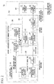
- FIG. 2 shows each constituent element of the device state estimation apparatus 50 and the device power consumption estimation apparatus 70 shown in FIG. 1 .
- the device state estimation apparatus 50 has a voltage and current measure 10, a harmonic calculator 20, a history characteristics detector 30, and an operating state estimator 40.
- the device power consumption estimation apparatus 70 has the device state estimation apparatus 50 and a device power consumption estimator 60.
- the apparatus of the embodiment has the device state estimation apparatus 50 that estimates the operating state of each home appliance from measurement data of the voltage and current of each home appliance, and the device power consumption estimation apparatus 70 that estimates and outputs the power consumption of each home appliance.
- the voltage and current measure 10 measures the voltage on the power feed line and the current flowing in the power feed line at a fixed period, and records the time and time-sequence data of the voltage and current.
- the harmonic calculator 20 has an operating state change detector 21, a characteristic waveform extractor 22, and an FFT operator 23 (first FFT operator).
- the operating state change detector 21 receives the time and the time-sequence voltage and current data as input and, from these data, detects and outputs to the characteristic waveform extractor 22 the operating state change time.
- the operating state change time refers to a time at which an operating state changes, for example, when a home appliance changes from ON to OFF or OFF to ON and, the time at which the washing machine operating mode changes from "wash" to "rinse". There may not be just one of these operating state change times, but a plurality thereof.
- the characteristic waveform extractor 22 extracts a characteristic waveform before and after a change time, from the change times detected by the operating state change detector 21 and from the measurement data of voltage and current.
- the FFT operator 23 performs an FFT (fast Fourier transform) on the characteristic current waveform detected by the characteristic waveform extractor 22 and calculates the FFT coefficients of harmonics.
- FFT fast Fourier transform
- the history characteristics detector 30 has a device history characteristics database 31 and a device history characteristics detector 32.
- the device history characteristics database 31 records beforehand the characteristics of the current or power time variations of at least one device. This mainly assumes a device that has an inverter, such inverter operating by PWM or the like, varying the current magnitude and phase, so that the current harmonic components often vary with increase and decrease of the power consumption. When this occurs, each harmonic frequency component often describes a trace such as an arc on the complex plane. The characteristics of this trace are recorded beforehand.
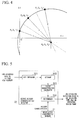
- FIG. 3 shows an example of PWM operation in inverters
- FIG. 4 describes an example of data recorded into the device history characteristics database 31.
- a home appliance not having an inverter has harmonic characteristics in accordance with one operating state.
- the harmonic characteristics vary in accordance with PWM operation or the like.
- PWM is a system in which a pulse stream of a large number of pulses (shown as Vout in FIG. 3 ) is generated during a half-cycle of the output waveform (shown as Vout' in FIG. 3 ), the equivalent voltage of the pulse widths thereof being made to vary as a sine wave, thereby obtaining a smooth output of Vout' with few low-order harmonics.
- the harmonics characteristic of an inverter home appliance Because the phase and amplitude are varied in PWM, in the harmonics characteristic of an inverter home appliance the harmonics describe a curve that passes through the origin. Making use of this characteristic, the trace of each order of harmonic is extracted and it is estimated from the characteristic trace (statistical information of the time-sequence data) which inverter home appliance is being operated.
- a characteristic of the trace is the center coordinate and radius.
- the center coordinates and radii thereof are taken in the same manner to be the characteristics. If there is no simultaneous PWM operation, each of the respective traces can be extracted separately. However, when there is simultaneous PWM operation, if the characteristics as shown in FIG. 4 are taken to be the center coordinates c, the radii r, and the angular velocities ⁇ , it is possible to synthesize the harmonic trace during simultaneous operation, enabling estimation of multiply operating inverter home appliances by selecting a combined trace that is most similar to the measured trace.
- the device history characteristics detector 32 calculates the time-variation characteristics from the time and the time-sequence data of voltage and current, compares the calculated characteristics with information in the device history characteristics database 31, and detects devices in the ON operating state.
- the ON operating state refers to the state (powered state) in which current is flowing in the device and power is being consumed. That is, the ON state may include both the state in which the device is powered and operating and the state in which the device, although being powered, is not operating (the so-called sleep state, standby state, or other state).
- the time-variation characteristics are mainly assumed to be the traces of each harmonic component. In comparing the traces stored in the device history characteristics database 31 and the calculated traces, a judgment can be made by coincidence or coincidence within some range between the radii and center coordinates of the arcs.
- FIG. 5 shows the constitution of the device history characteristics detector 32 shown in FIG. 2 .
- the device history characteristics detector 32 has an FFT operator 321 (second FFT operator), a storage 322, a history characteristics calculator 323, and a determiner 324.
- the FFT operator 321 breaks down the time and the time-sequence data of voltage and current into one or more current or power waveform frequency components. Both these both frequency components and the times are stored into the storage 322.
- the history characteristics calculator 323 calculates characteristics (frequency characteristics) that represent how the frequency components vary with time, from the time and current or power frequency components read out from the storage 322.
- the determiner 324 compares the time-variation characteristics of the device current or power output by the device history characteristics database 31 and the characteristics output by the history characteristics calculator 323 and, if there is coincidence, takes that a device to be in the ON operating state and outputs the name of that device along with the time.
- the operating state estimator 40 has a device characteristics database 41 (device characteristics database), a harmonic weighting distance calculator 42, and a device operating state estimator 43.
- the FFT coefficients of harmonics of each operating state of each home appliance are recorded into the device characteristics database 41 beforehand, and data is output to the harmonic weighting distance calculator 42.
- the harmonic weighting distance calculator 42 calculates the weighting distance of the calculated FFT harmonic coefficients of the current waveform and the FFT harmonic coefficients of each operating state of each home appliance read out from the device characteristics database 41. Because determining the distances for all operating states increases the amount of calculation and the size of memory, the ON operating device information detected by the device history characteristics detector 32 is used to calculate the harmonic weighting distance for only operating states of all the operating states that match the ON operating device information.
- the device operating state estimator 43 selects and outputs the operating state that best matches the state of the harmonics of the operating state having the smallest distance, from the weighting distances calculated by the harmonic weighting distance calculator 42.
- the device power consumption estimator 60 has a power consumption database 61 and a power consumption estimator 62.
- a regression model obtained from the relationship between the FFT harmonic coefficients of each operating state and the power consumption of each home appliance is stored into the power consumption database 61 beforehand and output to the power consumption estimator 62.
- the power consumption estimator 62 based on the operating state output by the device operating state estimator 43, reads out the corresponding regression model from the power consumption database 61 and estimates and outputs the power consumption.
- FIG. 6 is a flowchart showing the overall flow of power consumption estimation processing in the device power consumption estimation apparatus 70 of the present embodiment
- FIG. 7A through FIG. 7D show an example of the processing data in the flowchart of FIG. 6 .
- the voltage and current measure 10 inputs the recorded times, along with the time-sequence data of voltage and current (time-sequence data shown in FIG. 7A ) to the operating state change detector 21 (step ST1).
- the operating state change detector 21 from the times and the voltage and current time-sequence data, detects the times of changes in the operating state (the change times in the operating state shown in FIG. 7B ) and outputs the times of change of the operating state to the characteristic waveform extractor 22 that follows (step ST2).
- the input of the characteristic waveform extractor 22 is the time and the voltage and current time-sequence data and the times of changes in operating state detected by the operating state change detector 21.
- the harmonic weighting distance calculator 42 compares the voltage and current data before and after the times of change in the operating state to estimate the home appliance that changed its operating state. If there is a plurality of operating state change times, the same processing is performed with respect to all the times. As a result, the device operating state estimator 43 calculates the results of time-sequence estimation of the times and operating states (time-sequence estimation results shown in FIG. 7C ) for each home appliance, and outputs these to the power consumption estimator 62 that follows (step ST3, described in detail below).
- the input of the power consumption estimator 62 is the times and the operating state time-sequence estimation results for each home appliance calculated by the device operating state estimator 43.
- a power consumption estimation model corresponding to the operation state is prepared in the power consumption database 61 beforehand, and the power consumption estimator 62 uses the model to estimate the power consumption (step ST4).
- the power consumption estimator 62 outputs the time and the time-sequence power consumption estimation results for each home appliance (the time and power consumption time-sequence estimation results shown in FIG. 7D ) (step ST5).
- FIG. 8 is a flowchart showing the flow of processing to detect the operating state change times (step ST2) in the flowchart of FIG. 6
- FIG. 9A through FIG. 9C show an example of the processing data in the flowchart of FIG. 8 .
- the voltage and current measure 10 inputs the recorded times along with the time-sequence data of voltage and current (time-sequence data shown in FIG. 9A ) to the operating state change detector 21 (step ST2-1).
- the operating state change detector 21 calculates the effective value of the current (time-varying data of the current effective value shown FIG. 9B ) from the current time-sequence data (step ST2-2).
- the calculation interval used in calculating the effective value may be arbitrary. For example, although the shorter the calculation interval is the better is the time resolution when estimating the operating state or power consumption, the amount of operation increases. In contrast, although a lengthened interval reduces the detection error rate, operating state changes that need to be detected cannot be detected, thereby reducing the estimation accuracy.
- the operating state change detector 21 performs a continuous wavelet transformation on the time-sequence data of the current effective value (step ST2-3). This transformation enables capture of current variations. By capturing changes in the current, it can be thought that all changes including not only the ON and OFF states of the home appliance, but also changes in the power consumption of an inverter home appliance and changes in the operating mode of a continuously operating home appliance can be detected.
- the operating state change detector 21 extracts the wavelet coefficients in the time direction in some scale the extracted cross-section view is shown in FIG. 9C ) and compares the wavelet coefficients with a threshold value (step ST2-4).
- a threshold value An arbitrary value may be used for the scale.
- the size of the wavelet coefficient relates to the amount of current change. Therefore, the threshold is set and a comparison is made with the threshold, thereby enabling control of the amount of current change to be detected.
- a positive wavelet coefficient indicates an increase in current and a negative wavelet coefficient indicates a decrease in current. Given this, to detect an increase in current, a positive threshold is set, and to detect a decrease in current, a negative threshold is set.
- the operating state change detector 21 determines the time at an apex of a convex part at which the wavelet coefficient is judged as been larger or smaller than the threshold (step ST2-5).
- the operating state change detector 21 outputs the detected time as the operating state change time (step ST2-6). If there is a plurality of operating state change times, the change times for the plurality of operating state changes are output.
- FIG. 10 is a flowchart showing the flow of processing to estimate the operating state of a home appliance in the flowchart of FIG. 6 (step ST3).
- FIG. 11A through FIG. 11D show an example of the processing data in the flowchart of FIG. 10
- FIG. 12A and FIG. 12B show examples of the method of distance calculation in the flowchart of FIG. 10 .
- the operating state change times and the time-sequence data of the voltage and current are input to the characteristic waveform extractor 22 (step ST3-1).
- the characteristic waveform extractor 22 calculates and compares the characteristic waveforms before and after the time of change in the operating state (step ST3-2).
- the waveforms ⁇ t before and ⁇ t after the time of the change in the operating state are compared. This time ⁇ t must be determined considering the time constant of the operating state change, so that the waveform during the change is not referenced.
- the method of extracting a current differential waveform before and after the time of change is as follows.
- the FFT operator 23 performs an FFT on all of the current characteristic waveforms calculated by the characteristic waveform extractor 22 and calculates the harmonics (step ST3-3).
- the voltage waveform is referenced, and the waveform is extracted from the time at which the voltage phase is zero.
- the fundamental phase is adjusted and, as a result of this processing, the phase change of the fundamental can also be used as reference information when estimating the operating state.
- the device history characteristics detector 32 calculates the time-varying characteristics and compares the calculated characteristics (shown in FIG. 11B ) with information in the device history characteristics database 31 (shown in FIG. 11A ), and detects a device that is in the ON operating state (step ST3-4).
- a device that has an inverter in which the harmonic components of the current often vary together with an increase and decrease of the power consumption.
- each harmonic frequency component often describes a trace such as an arc on the complex plane.
- a judgment can be made regarding coincidence or coincidence within some range between the radii and center coordinates of the calculated arcs and the values in the device history characteristics database 31.
- Arcs having a large radius for low-order harmonics can be treated as vectors that are straight-line approximations thereof.
- the harmonic weighting distance calculator 42 considers the ON-state device and calculates the weighting distance between the characteristics in the device characteristics database 41 (shown in FIG. 11C ) and the calculated harmonics (shown in FIG. 11D ) (step ST3-5).
- the distances between the calculation result (FFT coefficients) and the characteristics in the device characteristics database 41 being calculated.
- the calculated distances for each order are accumulated and taken as the final distance.
- the harmonic FFT coefficients calculated in the FFT operator 23 are plotted on polar coordinates and, taking the distance as being separated between a phase and the size of an absolute value, each distance is calculated and each is multiplied by the weight ⁇ and ⁇ coefficients to calculate the distance.
- ⁇ and ⁇ are arbitrary, they may be varied in accordance with the characteristics of the home appliance.
- the value of ⁇ may be made large to place weight on the phase.
- the distance is calculated with respect to all operating states, because the amount of calculation and the memory size become large, the ON operating state device information detected by the device history characteristics detector 32 is used. Of all of the operating states, the distance is calculated for only operating states matching the ON operating state information. This enables not only a reduction of the amount of calculation and the memory size, but also a reduction in the estimation errors, thereby improving the estimation accuracy.
- the device operating state estimator 43 compares the weighting distances calculated by the harmonic weighting distance calculator 42, selects an operating state having the smallest distance (step ST3-6), and outputs this as the estimation result. By doing this, the device operating state estimator 43 outputs the time corresponding to the change time and the operating state time-sequence estimation results for each home appliance (step ST3-7).
- the power consumption estimator 62 from the time and the operating state time-sequence estimation results for each home appliance calculated by the device operating state estimator 43, reads out a corresponding power consumption model from the power consumption database 61.
- FIG. 13 describes the power consumption estimation model in the power consumption estimation processing (step ST4) in accordance with the operating state in the flowchart of FIG. 6 .
- the power consumption can be expressed by a regression model of the first-, third-, and fifth-order harmonic components of current. That is, because the power consumption of the home appliance has a high correlation with the power spectrum of the various orders, and particularly the low orders, of harmonics, this can be utilized in using a regression model relating the harmonic power spectrum and the power consumption. Because the device operating state estimator 43 outputs the time and the operating states, from the harmonic information during the operating state, the power spectrum is calculated and the power consumption is calculated from this and the regression model.
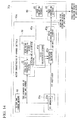
- FIG. 14 shows the constitution of the device state estimation apparatus 50a and the device power consumption estimation apparatus 70a of the present embodiment.
- parts that are the same as ones in FIG. 2 are assigned the same reference numerals and the description thereof might be omitted.
- the device state estimation apparatus 50a has a voltage and current measure 10, a harmonic calculator 20a, a history characteristics detector 30, and an operating state estimator 40a.
- the device power consumption estimation apparatus 70a has the device state estimation apparatus 50a and a device power consumption estimator 60.
- the apparatus of the present embodiment has the device state estimation apparatus 50a that estimates the operating state of each home appliance from measurement data of the voltage and current of each home appliance, and the device power consumption estimation apparatus 70a that estimates and outputs the power consumption of each home appliance.
- the voltage and current measure 10 and the history characteristics detector 30 are the same as those of the device state estimation apparatus 50, and the device power consumption estimator 60 is the same as that of the device power consumption estimation apparatus 70.
- the harmonic calculator 20a has an FFT operator 23a (first FFT operator).
- the FFT operator 23a performs an FFT on the current or voltage waveform and calculates the FFT coefficients of harmonics.
- the operating state estimator 40a has a device characteristics database 41a, a likelihood calculator 42a, and a device operating state estimator 43a.
- the device characteristics database 41a records beforehand the FFT coefficients of harmonics of each operating state of each home appliance and outputs the data to the likelihood calculator 42a.
- the difference between this and the device characteristics database 41 is that the device characteristics database 41a records information of the distribution of the harmonic components or distribution of the FFT coefficients of each operating state. For example, if this distribution is a normal distribution, the mean value and the deviation or variance are recorded into the device characteristics database 41 a and output to the likelihood calculator 42a.
- the likelihood calculator 42a generates a likelihood function of each operating state of each home appliance read out from the device characteristics database 41a and calculates the likelihood of the calculated current waveform harmonics. Because determining the likelihood for all operating states increases the amount of calculation and the memory size, the ON operating device information detected by the device history characteristics detector 32 is used to calculate the likelihood for only operating states of all the operating states that match the ON operating device information.
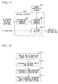
- FIG. 15 shows the constitution of the likelihood calculator 42a shown in FIG. 14 .
- the likelihood calculator 42a has an operating state combination generator 421, a likelihood function generator 422, and a likelihood evaluator 423.
- the operating state combination generator 421 generates, from among combinations of all device operating states, candidates for operating state combinations matching ON operating state devices output by the device history characteristics detector 32.
- the likelihood function generator 422 generates, with respect to the combination candidates, a likelihood function from the characteristics of each operating state of each home appliance read out from the device characteristics database 41 a.
- the likelihood evaluator 423 uses the likelihood function to calculate the likelihood of the calculated harmonics and outputs these as sets, combined with the operating states.
- the device operating state estimator 43a selects an operating state having the largest likelihood from among the likelihoods calculated by the likelihood calculator 42a, and outputs that operating state.
- FIG. 16 is a flowchart showing the overall flow of power consumption estimation processing in the device power consumption estimation apparatus 70a of the present embodiment
- FIG. 17A through FIG. 17C show an example of the processing data in the flowchart of FIG. 16 .
- the voltage and current measure 10 inputs the recorded times and voltage and current time-sequence data (time-sequence data in FIG. 17A ) to the FFT operator 23a and the device history characteristics detector 32 (step ST11).
- the input of the FFT operator 23a and the device history characteristics detector 32 is the time and the time-sequence data of the voltage and current.
- the device operating state estimator 43a estimates the operating states for each time, calculates the time and the time-sequence estimation results (time-sequence estimation results shown in FIG. 17B ) of the operating states for each home appliance, and outputs these to the power consumption estimator 62 that follows (step ST12, to be described in detail later).
- the input of the power consumption estimator 62 is the time and the time-sequence estimation results for operating states for each home appliance calculated by the device operating state estimator 43a.
- a power consumption estimation model corresponding to the operating states is prepared in the power consumption database 61, and the power consumption estimator 62 estimates the power consumption using this model (step ST13).
- the power consumption estimator 62 outputs the times and the time-sequence estimation results for power consumption for each home appliance (times and power consumption time-sequence estimation results for each home appliance shown in FIG. 17C ) (step ST14).
- step ST12 will be described in detail.
- FIG. 18 is a flowchart showing the flow of processing to estimate the operating state of a home appliance in the flowchart of FIG. 16 (step ST12).
- FIG. 19A to FIG. 19C show an example of the processing data in the flowchart of FIG. 18 .
- the change times and voltage and current time-sequence data of an operating state are input to the FFT operator 23a (step ST12-1).
- an FFT is performed on the current or power characteristics waveform to calculate harmonics (step ST12-2). Also, for the current data, the voltage waveform is referenced, and the waveform is extracted at the time at which the voltage phase is zero. By referencing the voltage, the fundamental phase is adjusted and, as a result of this processing, the phase change of the fundamental can also be used as reference information when estimating the operating state.
- the device history characteristics detector 32 calculates the time-variation characteristics from the time and the voltage and current time-sequence data and compares the calculated characteristics (shown in FIG. 19B ) with information in the device history characteristics database 31 (shown in FIG. 19A ), and detects a device that is in the ON operating state (step ST12-3).
- the likelihood calculator 42a considers the ON operating device and, from the characteristics in the device characteristics database 41a, calculates the likelihood of the calculated harmonic ( FIG. 19C ) (step ST12-4).
- the likelihood calculator 42a From among combinations of all device operating states, the likelihood calculator 42a generates combination candidates that match ON operating state devices output by the device history characteristics detector 32. For example, in the case of the result being that a washing machine is ON, combinations that include the washing machine being in the ON state, for example, "rinse” for a washing machine or, in the case of a microwave oven, "500 W warming” would be generated as combination candidates. With respect to these combination candidates, a likelihood function is generated from the characteristics of each operating state of each home appliance read out from the device characteristics database 41a. As shown in FIG. 19C , it is possible to generate a likelihood function from the distribution information in the device characteristics database 41a, for example, from the mean value and deviation of the distribution if the distribution is a normal distribution. Using this likelihood function, the likelihood of the calculated harmonics are calculated and output as sets with the operating states.
- the device operating state estimator 43a compares the likelihoods calculated by the likelihood calculator 42a, selects an operating state having the largest likelihood (step ST12-5), and outputs this as the estimation result. In this manner, the time corresponding to the change time and operating state time-sequence estimation results are output for each home appliance (step ST12-6).
- the device state estimation apparatus 50 estimates the operating state only at the time of a change in the operating state
- the device state estimation apparatus 50a of the present embodiment can estimate the operating state at all times, thereby improving accuracy. Additionally, because it uses the likelihood to evaluate, the estimation accuracy is improved, because it is possible to perform evaluation using a uniform index from low-order to high-order harmonics.
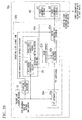
- FIG. 20 shows the constitution of the device state estimation apparatus 50b and the device power consumption estimation apparatus 70b of the present embodiment.
- parts that are the same as ones in FIG. 14 are assigned the same reference numerals, and the descriptions thereof might be omitted.
- the device state estimation apparatus 50b has a voltage and current measure 10, an operating state change detector 21, a harmonic calculator 20a (FFT operator 23a), a history characteristics detector 30 (device history characteristics database 31 and device history characteristics detector 32), and an operating state estimator 40a (device characteristics database 41a, likelihood calculator 42a, and device operating state estimator 43a).
- the device power consumption estimation apparatus 70b has a device state estimation apparatus 50b and a device power consumption estimator 60 (power consumption database 61 and power consumption estimator 62).
- the apparatus of the present embodiment has the device state estimation apparatus 50b that estimates the operating state of each home appliance from measurement data of the voltage and current of each home appliance, and the device power consumption estimation apparatus 70b that estimates and outputs the power consumption of each home appliance.
- the device state estimation apparatus 50b is the device state estimation apparatus 50a to which is added the operating state change detector 21 in the device state estimation apparatus 50.
- the power consumption estimation processing in the device power consumption estimation apparatus 70b of the present embodiment is the same as the power consumption estimation processing in the device power consumption estimation apparatus 70a shown in FIG. 16 , and differs with regard to the details of the processing to estimate the operating state of a home appliance (step ST12). This step ST12 will be described in detail.
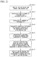
- FIG. 21 is a flowchart showing the flow of processing to estimate the operating state of a home appliance in the device power consumption estimation apparatus 70b of the present embodiment.
- the voltage and current measure 10 inputs the recorded times and voltage and current time-sequence data to the operating state change detector 21 (step ST12b-1).
- the operating state change detector 21 detects the operating state change time (current waveform discontinuity point) from the time and the voltage and current time-sequence data (step ST12b-2) and outputs this operating state change time to the operating state estimator 40a.
- the FFT operator 23a calculates harmonics using an FFT (step ST12b-3), the device history characteristics detector 32 compares the characteristics in the device history characteristics database 31 and the calculated characteristics and detects devices in the ON operating state (step ST12b-4), and the likelihood calculator 42a, from the characteristics in the device characteristics database 41a, calculates the likelihood of the calculated harmonics (step ST12b-5).
- the steps ST12b-3 to ST12b-5 are the same, respectively, as the steps ST12-2 to ST12-4 in the device state estimation apparatus 50a.
- the likelihood calculator 42a compares the calculated likelihoods, and selects an operating state having the largest likelihood as the estimation result (step ST12b-6). However, before and after the change time of the operating state ( ⁇ t) the likelihood calculator 42a of the device state estimation apparatus 50b discards the estimation results or skips that process, thereby holding the previous (immediately before the change time of the operating state ( ⁇ t)) operating state estimation result.
- the device operating state estimator 43a corrects the estimation result before and after the time of a change in the operating state ( ⁇ t) and outputs the time corresponding to the change time and operating state time-sequence estimation results for each home appliance (step ST12b-7).
- the device state estimation apparatus 50b By the constitution of the above-noted device state estimation apparatus 50b, estimation before and after an operating state change is either not performed or the estimation results are discarded. Because the state is in transition between before and after a change in operation, the harmonics thereof change greatly. For this reason, the harmonic characteristics during the transition often do not coincide with the characteristics in the device characteristics database 41a, this being a cause of estimation errors. Given this, in the device state estimation apparatus 50b, it is possible to reduce estimation errors by not performing estimation during a transition period.
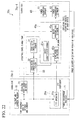
- FIG. 22 shows the constitution of the device power consumption estimation apparatus 70c.
- the device status detection and device power consumption detection functions of the device power consumption estimation apparatus 70b are divided between a server-side 70_c1 and a local_side 70_c2.
- the server-side 70_c1 has a history characteristics detector 30 (device history characteristics database 31 and device history characteristics detector 32), an operating state estimator 40a (device characteristics database 41 a, likelihood calculator 42a, and device operating state estimator 43a), and a device power consumption estimator 60 (power consumption database 61 and power consumption estimator 62).
- the local-side 70_c2 has a voltage and current measure 10, an operating state change detector 21, a harmonic calculator 20a (FFT operator 23a), and a power consumption receiver 71.
- the server-side 70_c1 estimates the power consumption based on the harmonic characteristics obtained from the local-side 70_c2, and transmits the results to the local-side 70_c2.
- the power consumption receiver 71 on the local-side 70_c2 receives the power consumption estimated by the server-side 70_c1 and displays the received power consumption at the local-side 70_c2.
- the results from the FFT operator 23a on the local-side 70_c2 are transmitted to the server-side 70_c1 via a network.
- an operating state having the largest likelihood is estimated from the results from the FFT operator 23 a, the power consumption is estimated, and the result is transmitted to the local-side 70_c2.
- the processing at each of the server-side 70_c1 and local-side 70_C2 is the same as in the device power consumption estimation apparatus 70b.
- the device state estimation apparatus and the device power consumption estimation apparatus of the present embodiment may be implemented by a program and a processor such as a CPU (central processing unit) that executes the program.
- a program implementing the above-noted functions of the device state estimation apparatus and the device power consumption estimation apparatus may run on a server, a smart meter, a smart tap, and a cloud computer, which are used in an HEMS (Home Energy Management System) that is a power consumption management system for devices in a home or the like, or on another server for the purpose of managing power consumption.
- HEMS Home Energy Management System
- the above-noted program may be recorded in a non-temporary computer-readable recording medium, and the program recorded on the medium may be read into a computer system and executed so as to perform control.
- computer system includes an operating system and hardware such as peripheral devices.
- computer-readable recording medium refers to a removable medium such as a flexible disk, an opto-magnetic disk, a ROM (read only memory), or a CD-ROM, or to a storage device built into a computer, such as a hard-disk.
- Each of the device state estimation apparatus and device power consumption estimation apparatus may be a computer program product including instructions, which are computer-readable when the computer program product is loaded into a computer processor and executed.
- the device state estimation apparatus and device power consumption estimation apparatus may be implemented in software, by downloading and installing a program via an external network such as the Internet.
Landscapes
- Engineering & Computer Science (AREA)
- Theoretical Computer Science (AREA)
- Physics & Mathematics (AREA)
- General Physics & Mathematics (AREA)
- General Engineering & Computer Science (AREA)
- Power Engineering (AREA)
- Computing Systems (AREA)
- Quality & Reliability (AREA)
- Automation & Control Theory (AREA)
- Remote Monitoring And Control Of Power-Distribution Networks (AREA)
Abstract
Description
- Embodiments described herein relate to a device state estimation apparatus, a device power consumption estimation apparatus, and a program.
- Art that separately measures the operating state of electrical devices, including inverters, used in the home and the like, that, rather than installing measuring instruments in each electrical device, non-invasively estimates the operating state of each electrical device, based on a measurement on the lead-in power line from a utility pole to the home has been proposed.
- When estimating the operating state of each electrical device, if a plurality of home appliances is simultaneously operating, the number of combinations in the estimation becomes extremely large, and the amount of operation time and amount of memory capacity used in the operation processing might increase. Additionally, because the number of combinations in the operation processing becomes extremely large, erroneous detection might more frequently occur.
-
-
Patent Reference 1 Japanese Laid-open Patent Publication No.2000-292465 -
Patent Reference 2 Japanese Laid-open Patent Publication No.2002-152971 -
Patent Reference 3 Japanese Laid-open Patent Publication No.2012-189526 - The problem that the present invention sets out to solve is that of providing a device state estimation apparatus, a device power consumption estimation apparatus, and a program capable of suppressing an increase in the operation time and memory capacity required for operation processing.
- According to one embodiment, a device state estimation apparatus includes a detector and an operating state estimator. The detector detects devices in the ON operating state, based on a comparison between a calculated one of a first characteristic of a current or power harmonic in a power feed line and a reference one of the first characteristic which has been predetermined for at least one device. The operating state estimator extracts at least one set of the second characteristics from plural sets of second characteristics associated with harmonic, which have been predetermined. Each set of the second characteristics is for operating states of each of the devices. The one set of the second characteristics is for operating states of the device in the ON operating state which is detected by the detector. The operating state estimator estimates the operating state of the device based on the similarity between the extracted one of the second characteristics and a calculated one of the second characteristics obtained from the current or power harmonic.
-
-
FIG. 1 shows the constitution of a devicestate estimation apparatus 50 and a device powerconsumption estimation apparatus 70 of an embodiment. -
FIG. 2 shows each constituent element of the devicestate estimation apparatus 50 and the device powerconsumption estimation apparatus 70 shown inFIG. 1 . -
FIG. 3 shows an example of PWM (pulse width modulation) operation in an inverter device. -
FIG. 4 describes an example of data recorded in a devicehistory characteristics database 31. -
FIG. 5 shows the constitution of the devicehistory characteristics detector 32 shown inFIG. 2 . -
FIG. 6 is a flowchart showing the overall flow of power consumption estimation processing in the device powerconsumption estimation apparatus 70 of the embodiment. -
FIG. 7A shows an example of time-sequence data of current and voltage in the flowchart ofFIG. 6 . -
FIG. 7B shows an example of operating state change time data in the flowchart ofFIG. 6 . -
FIG. 7C shows an example of time-sequence estimation results of the operating state in the flowchart ofFIG. 6 . -
FIG. 7D shows an example of time-sequence estimation results of the power consumption in the flowchart ofFIG. 6 . -
FIG. 8 is a flowchart showing the flow of detection processing of the change time of the operating state in the flowchart ofFIG. 6 . -
FIG. 9A shows an example of time-sequence data of current and voltage in the flowchart ofFIG. 8 . -
FIG. 9B shows an example of time-varying data of the current effective value in the flowchart ofFIG. 8 . -
FIG. 9C shows an example of a cross-sectional view obtained by extracting the wavelet coefficient in the flowchart ofFIG. 8 in the time direction. -
FIG. 10 is a flowchart showing the flow of processing to estimate the operating state of a home appliance in the flowchart ofFIG. 6 . -
FIG. 11A shows an example of characteristics recorded in the devicehistory characteristics database 31 in the flowchart ofFIG. 10 . -
FIG. 11B shows an example of calculated characteristics of the time variation in the flowchart ofFIG. 10 . -
FIG. 11C shows an example of characteristics recorded in thedevice characteristics database 41 in the flowchart ofFIG. 10 . -
FIG. 11D shows an example of harmonic data calculated in the flowchart ofFIG. 10 . -
FIG. 12A shows an example of a distance calculation method in the flowchart ofFIG. 10 . -
FIG. 12B shows an example of a distance calculation method in the flowchart ofFIG. 10 . -
FIG. 13 describes a power consumption estimation model in the power consumption estimation processing in accordance with the operating state in the flowchart ofFIG. 6 . -
FIG. 14 shows the constitution of a devicestate estimation apparatus 50a and a device powerconsumption estimation apparatus 70a of an embodiment. -
FIG. 15 shows the constitution of thelikelihood calculator 42a shown inFIG. 14 . -
FIG. 16 is a flowchart showing the overall flow of power consumption estimation processing in the device powerconsumption estimation apparatus 70a of the embodiment. -
FIG. 17A shows an example of time-sequence data of current and voltage in the flowchart ofFIG. 16 . -
FIG. 17B shows an example of time-sequence estimation results of the operating state in the flowchart ofFIG. 16 . -
FIG. 17C shows an example of results of time-sequence estimation of the power consumption in the flowchart ofFIG. 16 . -
FIG. 18 is a flowchart showing the flow of estimation processing of the operating state of a home appliance in the flowchart ofFIG. 16 . -
FIG. 19A shows an example of characteristics recorded in the devicehistory characteristics database 31 in the flowchart ofFIG. 18 . -
FIG. 19B shows an example of the calculated time variation characteristics in the flowchart ofFIG. 18 . -
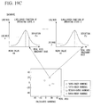
FIG. 19C shows an example of calculating the harmonic likelihood from the characteristics recorded in thedevice characteristics database 41a in the flowchart ofFIG. 18 . -
FIG. 20 shows the constitution of a devicestate estimation apparatus 50b and a device powerconsumption estimation apparatus 70b of an embodiment. -
FIG. 21 is a flowchart showing the flow of estimation processing of the operating state of a home appliance in the device powerconsumption estimation apparatus 70b of the embodiment. -
FIG. 22 shows the constitution of a device powerconsumption estimation apparatus 70c. - A device
state estimation apparatus 50 and a device powerconsumption estimation apparatus 70 of an embodiment will be described below, with references made to the drawings.FIG. 1 shows the constitution of the devicestate estimation apparatus 50 and the device powerconsumption estimation apparatus 70 of the embodiment, andFIG. 2 shows each constituent element of the devicestate estimation apparatus 50 and the device powerconsumption estimation apparatus 70 shown inFIG. 1 . - As shown in
FIG. 1 , the devicestate estimation apparatus 50 has a voltage andcurrent measure 10, aharmonic calculator 20, ahistory characteristics detector 30, and an operatingstate estimator 40. The device powerconsumption estimation apparatus 70 has the devicestate estimation apparatus 50 and a devicepower consumption estimator 60. - The apparatus of the embodiment has the device
state estimation apparatus 50 that estimates the operating state of each home appliance from measurement data of the voltage and current of each home appliance, and the device powerconsumption estimation apparatus 70 that estimates and outputs the power consumption of each home appliance. - The voltage and
current measure 10 measures the voltage on the power feed line and the current flowing in the power feed line at a fixed period, and records the time and time-sequence data of the voltage and current. - As shown in
FIG. 2 , theharmonic calculator 20 has an operatingstate change detector 21, acharacteristic waveform extractor 22, and an FFT operator 23 (first FFT operator). - The operating
state change detector 21 receives the time and the time-sequence voltage and current data as input and, from these data, detects and outputs to thecharacteristic waveform extractor 22 the operating state change time. The operating state change time refers to a time at which an operating state changes, for example, when a home appliance changes from ON to OFF or OFF to ON and, the time at which the washing machine operating mode changes from "wash" to "rinse". There may not be just one of these operating state change times, but a plurality thereof. - The
characteristic waveform extractor 22 extracts a characteristic waveform before and after a change time, from the change times detected by the operatingstate change detector 21 and from the measurement data of voltage and current. - The
FFT operator 23 performs an FFT (fast Fourier transform) on the characteristic current waveform detected by thecharacteristic waveform extractor 22 and calculates the FFT coefficients of harmonics. - The
history characteristics detector 30 has a devicehistory characteristics database 31 and a devicehistory characteristics detector 32. - The device
history characteristics database 31 records beforehand the characteristics of the current or power time variations of at least one device. This mainly assumes a device that has an inverter, such inverter operating by PWM or the like, varying the current magnitude and phase, so that the current harmonic components often vary with increase and decrease of the power consumption. When this occurs, each harmonic frequency component often describes a trace such as an arc on the complex plane. The characteristics of this trace are recorded beforehand. -
FIG. 3 shows an example of PWM operation in inverters, andFIG. 4 describes an example of data recorded into the devicehistory characteristics database 31. - A home appliance not having an inverter has harmonic characteristics in accordance with one operating state. In contrast, in home appliances that have an inverter, the harmonic characteristics vary in accordance with PWM operation or the like.
- PWM is a system in which a pulse stream of a large number of pulses (shown as Vout in
FIG. 3 ) is generated during a half-cycle of the output waveform (shown as Vout' inFIG. 3 ), the equivalent voltage of the pulse widths thereof being made to vary as a sine wave, thereby obtaining a smooth output of Vout' with few low-order harmonics. - Because the phase and amplitude are varied in PWM, in the harmonics characteristic of an inverter home appliance the harmonics describe a curve that passes through the origin. Making use of this characteristic, the trace of each order of harmonic is extracted and it is estimated from the characteristic trace (statistical information of the time-sequence data) which inverter home appliance is being operated. One example of a characteristic of the trace is the center coordinate and radius.
- If a plurality of inverters is operating, the center coordinates and radii thereof are taken in the same manner to be the characteristics. If there is no simultaneous PWM operation, each of the respective traces can be extracted separately. However, when there is simultaneous PWM operation, if the characteristics as shown in
FIG. 4 are taken to be the center coordinates c, the radii r, and the angular velocities ω, it is possible to synthesize the harmonic trace during simultaneous operation, enabling estimation of multiply operating inverter home appliances by selecting a combined trace that is most similar to the measured trace. - The device
history characteristics detector 32 calculates the time-variation characteristics from the time and the time-sequence data of voltage and current, compares the calculated characteristics with information in the devicehistory characteristics database 31, and detects devices in the ON operating state. The ON operating state refers to the state (powered state) in which current is flowing in the device and power is being consumed. That is, the ON state may include both the state in which the device is powered and operating and the state in which the device, although being powered, is not operating (the so-called sleep state, standby state, or other state). In this case as well, the time-variation characteristics are mainly assumed to be the traces of each harmonic component. In comparing the traces stored in the devicehistory characteristics database 31 and the calculated traces, a judgment can be made by coincidence or coincidence within some range between the radii and center coordinates of the arcs. -
FIG. 5 shows the constitution of the devicehistory characteristics detector 32 shown inFIG. 2 . The devicehistory characteristics detector 32 has an FFT operator 321 (second FFT operator), astorage 322, ahistory characteristics calculator 323, and adeterminer 324. - The
FFT operator 321 breaks down the time and the time-sequence data of voltage and current into one or more current or power waveform frequency components. Both these both frequency components and the times are stored into thestorage 322. Thehistory characteristics calculator 323 calculates characteristics (frequency characteristics) that represent how the frequency components vary with time, from the time and current or power frequency components read out from thestorage 322. Thedeterminer 324 compares the time-variation characteristics of the device current or power output by the devicehistory characteristics database 31 and the characteristics output by thehistory characteristics calculator 323 and, if there is coincidence, takes that a device to be in the ON operating state and outputs the name of that device along with the time. - The operating
state estimator 40 has a device characteristics database 41 (device characteristics database), a harmonicweighting distance calculator 42, and a device operatingstate estimator 43. - The FFT coefficients of harmonics of each operating state of each home appliance are recorded into the
device characteristics database 41 beforehand, and data is output to the harmonicweighting distance calculator 42. - The harmonic
weighting distance calculator 42 calculates the weighting distance of the calculated FFT harmonic coefficients of the current waveform and the FFT harmonic coefficients of each operating state of each home appliance read out from thedevice characteristics database 41. Because determining the distances for all operating states increases the amount of calculation and the size of memory, the ON operating device information detected by the devicehistory characteristics detector 32 is used to calculate the harmonic weighting distance for only operating states of all the operating states that match the ON operating device information. - The device
operating state estimator 43 selects and outputs the operating state that best matches the state of the harmonics of the operating state having the smallest distance, from the weighting distances calculated by the harmonicweighting distance calculator 42. - The device
power consumption estimator 60 has apower consumption database 61 and apower consumption estimator 62. - A regression model obtained from the relationship between the FFT harmonic coefficients of each operating state and the power consumption of each home appliance is stored into the
power consumption database 61 beforehand and output to thepower consumption estimator 62. - The
power consumption estimator 62, based on the operating state output by the device operatingstate estimator 43, reads out the corresponding regression model from thepower consumption database 61 and estimates and outputs the power consumption. - Next, the power consumption estimation processing in the device power
consumption estimation apparatus 70 of the present embodiment will be described, with references made to the drawings.FIG. 6 is a flowchart showing the overall flow of power consumption estimation processing in the device powerconsumption estimation apparatus 70 of the present embodiment, andFIG. 7A through FIG. 7D show an example of the processing data in the flowchart ofFIG. 6 . - The voltage and
current measure 10 inputs the recorded times, along with the time-sequence data of voltage and current (time-sequence data shown inFIG. 7A ) to the operating state change detector 21 (step ST1). - The operating
state change detector 21, from the times and the voltage and current time-sequence data, detects the times of changes in the operating state (the change times in the operating state shown inFIG. 7B ) and outputs the times of change of the operating state to thecharacteristic waveform extractor 22 that follows (step ST2). - The input of the
characteristic waveform extractor 22 is the time and the voltage and current time-sequence data and the times of changes in operating state detected by the operatingstate change detector 21. The harmonicweighting distance calculator 42 compares the voltage and current data before and after the times of change in the operating state to estimate the home appliance that changed its operating state. If there is a plurality of operating state change times, the same processing is performed with respect to all the times. As a result, the device operatingstate estimator 43 calculates the results of time-sequence estimation of the times and operating states (time-sequence estimation results shown inFIG. 7C ) for each home appliance, and outputs these to thepower consumption estimator 62 that follows (step ST3, described in detail below). - The input of the
power consumption estimator 62 is the times and the operating state time-sequence estimation results for each home appliance calculated by the device operatingstate estimator 43. A power consumption estimation model corresponding to the operation state is prepared in thepower consumption database 61 beforehand, and thepower consumption estimator 62 uses the model to estimate the power consumption (step ST4). Thepower consumption estimator 62 outputs the time and the time-sequence power consumption estimation results for each home appliance (the time and power consumption time-sequence estimation results shown inFIG. 7D ) (step ST5). - Next, each of the above-noted steps ST2 to ST4 will be described in detail.
-
FIG. 8 is a flowchart showing the flow of processing to detect the operating state change times (step ST2) in the flowchart ofFIG. 6 , andFIG. 9A throughFIG. 9C show an example of the processing data in the flowchart ofFIG. 8 . - All of each part of the processing in this flow is performed in the operating
state change detector 21. - The voltage and
current measure 10 inputs the recorded times along with the time-sequence data of voltage and current (time-sequence data shown inFIG. 9A ) to the operating state change detector 21 (step ST2-1). - The operating
state change detector 21 calculates the effective value of the current (time-varying data of the current effective value shownFIG. 9B ) from the current time-sequence data (step ST2-2). The calculation interval used in calculating the effective value may be arbitrary. For example, although the shorter the calculation interval is the better is the time resolution when estimating the operating state or power consumption, the amount of operation increases. In contrast, although a lengthened interval reduces the detection error rate, operating state changes that need to be detected cannot be detected, thereby reducing the estimation accuracy. - The operating
state change detector 21 performs a continuous wavelet transformation on the time-sequence data of the current effective value (step ST2-3). This transformation enables capture of current variations. By capturing changes in the current, it can be thought that all changes including not only the ON and OFF states of the home appliance, but also changes in the power consumption of an inverter home appliance and changes in the operating mode of a continuously operating home appliance can be detected. - From the results of the continuous wavelet transformation, the operating
state change detector 21 extracts the wavelet coefficients in the time direction in some scale the extracted cross-section view is shown inFIG. 9C ) and compares the wavelet coefficients with a threshold value (step ST2-4). An arbitrary value may be used for the scale. By expanding and contracting the wavelet basis function, the smaller the scale, the more the wavelet coefficients change in response to a current change having a small time constant. In contrast, if the scale is large, the wavelet coefficients change in response to a current change having a large time constant and the wavelet coefficients do not change with a current change having a small time constant. Therefore, adjusting this scale enables control of the time constant of current change to be detected. Also, the size of the wavelet coefficient relates to the amount of current change. Therefore, the threshold is set and a comparison is made with the threshold, thereby enabling control of the amount of current change to be detected. A positive wavelet coefficient indicates an increase in current and a negative wavelet coefficient indicates a decrease in current. Given this, to detect an increase in current, a positive threshold is set, and to detect a decrease in current, a negative threshold is set. - Because the operating state changes at the time at which the wavelet coefficient is maximum, the operating
state change detector 21 determines the time at an apex of a convex part at which the wavelet coefficient is judged as been larger or smaller than the threshold (step ST2-5). - The operating
state change detector 21 outputs the detected time as the operating state change time (step ST2-6). If there is a plurality of operating state change times, the change times for the plurality of operating state changes are output. -
FIG. 10 is a flowchart showing the flow of processing to estimate the operating state of a home appliance in the flowchart ofFIG. 6 (step ST3).FIG. 11A through FIG. 11D show an example of the processing data in the flowchart ofFIG. 10 , andFIG. 12A and FIG. 12B show examples of the method of distance calculation in the flowchart ofFIG. 10 . - The operating state change times and the time-sequence data of the voltage and current are input to the characteristic waveform extractor 22 (step ST3-1).
- The
characteristic waveform extractor 22 calculates and compares the characteristic waveforms before and after the time of change in the operating state (step ST3-2). When doing that, because instability makes it difficult to capture the characteristic of a waveform during a change in the operating state, the waveform during the change is not used. For this reason, the waveforms Δt before and Δt after the time of the change in the operating state are compared. This time Δt must be determined considering the time constant of the operating state change, so that the waveform during the change is not referenced. - The method of extracting a current differential waveform before and after the time of change is as follows.
- (1) With regard judgment of a change in home appliance device from OFF to ON or ON to OFF, extraction is done as the differential waveform between the waveforms before and after the change time.
- (2) The judgment of a change in the operating state of a home appliance in the ON operating state is made by determining all combinations of differences between the waveform after the change time and the total of the waveforms of (N-1) ON operating states.
- In order to evaluate the possibility of all operating state changes in subsequent steps, the characteristic waveforms for all case are calculated in this step.
- The
FFT operator 23 performs an FFT on all of the current characteristic waveforms calculated by thecharacteristic waveform extractor 22 and calculates the harmonics (step ST3-3). For the current data, the voltage waveform is referenced, and the waveform is extracted from the time at which the voltage phase is zero. By referencing the voltage, the fundamental phase is adjusted and, as a result of this processing, the phase change of the fundamental can also be used as reference information when estimating the operating state. - From the times and the voltage and current time-sequence data, the device
history characteristics detector 32 calculates the time-varying characteristics and compares the calculated characteristics (shown inFIG. 11B ) with information in the device history characteristics database 31 (shown inFIG. 11A ), and detects a device that is in the ON operating state (step ST3-4). This mainly assumes a device that has an inverter, in which the harmonic components of the current often vary together with an increase and decrease of the power consumption. When this occurs, each harmonic frequency component often describes a trace such as an arc on the complex plane. Given this, to identify the ON operating device, a judgment can be made regarding coincidence or coincidence within some range between the radii and center coordinates of the calculated arcs and the values in the devicehistory characteristics database 31. Arcs having a large radius for low-order harmonics can be treated as vectors that are straight-line approximations thereof. - If a plurality of inverters is operating, if the characteristics are taken to be the center coordinates, the radii, and the angular velocities, it is possible to synthesize the harmonic trace during multiple operation, enabling estimation of a plurality of operating inverter home appliances by selecting a trace that is most similar to the measured trace.
- The harmonic
weighting distance calculator 42 considers the ON-state device and calculates the weighting distance between the characteristics in the device characteristics database 41 (shown inFIG. 11C ) and the calculated harmonics (shown inFIG. 11D ) (step ST3-5). - As indicated by the Euclidean distance on the complex plane in
FIG. 12A , with the distance for each order of harmonic taken as being (x1 - x2) + (yl- y2), the distances between the calculation result (FFT coefficients) and the characteristics in thedevice characteristics database 41 being calculated. The calculated distances for each order are accumulated and taken as the final distance. Alternatively, as shown inFIG. 12B , the harmonic FFT coefficients calculated in theFFT operator 23 are plotted on polar coordinates and, taking the distance as being separated between a phase and the size of an absolute value, each distance is calculated and each is multiplied by the weight α and β coefficients to calculate the distance. For each order of harmonic, polar coordinates are used, the distance being taken as α x abs(r1-r2) + β x (Θ1-Θ2), and the weighting distance between the calculation results (FFT coefficients) and the characteristics in thedevice characteristics database 41 being calculated. Although the α and β are arbitrary, they may be varied in accordance with the characteristics of the home appliance. The value of β may be made large to place weight on the phase. - When calculating the distance, if the distance is calculated with respect to all operating states, because the amount of calculation and the memory size become large, the ON operating state device information detected by the device
history characteristics detector 32 is used. Of all of the operating states, the distance is calculated for only operating states matching the ON operating state information. This enables not only a reduction of the amount of calculation and the memory size, but also a reduction in the estimation errors, thereby improving the estimation accuracy. - The device
operating state estimator 43 compares the weighting distances calculated by the harmonicweighting distance calculator 42, selects an operating state having the smallest distance (step ST3-6), and outputs this as the estimation result. By doing this, the device operatingstate estimator 43 outputs the time corresponding to the change time and the operating state time-sequence estimation results for each home appliance (step ST3-7). - The
power consumption estimator 62, from the time and the operating state time-sequence estimation results for each home appliance calculated by the device operatingstate estimator 43, reads out a corresponding power consumption model from thepower consumption database 61. -
FIG. 13 describes the power consumption estimation model in the power consumption estimation processing (step ST4) in accordance with the operating state in the flowchart ofFIG. 6 . As shown inFIG. 13 , because much of the current is made up of the first-, third-, and fifth-order components, the power consumption can be expressed by a regression model of the first-, third-, and fifth-order harmonic components of current. That is, because the power consumption of the home appliance has a high correlation with the power spectrum of the various orders, and particularly the low orders, of harmonics, this can be utilized in using a regression model relating the harmonic power spectrum and the power consumption. Because the device operatingstate estimator 43 outputs the time and the operating states, from the harmonic information during the operating state, the power spectrum is calculated and the power consumption is calculated from this and the regression model. - By the constitution of the above-described embodiment, when a plurality of home appliances is simultaneously operating, it is possible to reduce an increase in the amount of calculations and the memory size and the occurrence of estimation errors caused by an increase in the number of combinations of operating states of the plurality of target devices. In this manner, by limiting the combined states of the home appliance beforehand, detection errors by the device
state estimation apparatus 50 can be reduced, and the accuracy of power consumption estimation by the device powerconsumption estimation apparatus 70 can be improved. - Continuing, the device
state estimation apparatus 50a and the device powerconsumption estimation apparatus 70a of the present embodiment will be described, with references made to the drawings.FIG. 14 shows the constitution of the devicestate estimation apparatus 50a and the device powerconsumption estimation apparatus 70a of the present embodiment. InFIG. 14 , parts that are the same as ones inFIG. 2 are assigned the same reference numerals and the description thereof might be omitted. - As shown in
FIG. 14 , the devicestate estimation apparatus 50a has a voltage andcurrent measure 10, aharmonic calculator 20a, ahistory characteristics detector 30, and an operatingstate estimator 40a. The device powerconsumption estimation apparatus 70a has the devicestate estimation apparatus 50a and a devicepower consumption estimator 60. - The apparatus of the present embodiment has the device
state estimation apparatus 50a that estimates the operating state of each home appliance from measurement data of the voltage and current of each home appliance, and the device powerconsumption estimation apparatus 70a that estimates and outputs the power consumption of each home appliance. - The voltage and
current measure 10 and thehistory characteristics detector 30 are the same as those of the devicestate estimation apparatus 50, and the devicepower consumption estimator 60 is the same as that of the device powerconsumption estimation apparatus 70. - The
harmonic calculator 20a has anFFT operator 23a (first FFT operator). TheFFT operator 23a performs an FFT on the current or voltage waveform and calculates the FFT coefficients of harmonics. - The operating
state estimator 40a has adevice characteristics database 41a, alikelihood calculator 42a, and a device operatingstate estimator 43a. - The
device characteristics database 41a records beforehand the FFT coefficients of harmonics of each operating state of each home appliance and outputs the data to thelikelihood calculator 42a. The difference between this and thedevice characteristics database 41 is that thedevice characteristics database 41a records information of the distribution of the harmonic components or distribution of the FFT coefficients of each operating state. For example, if this distribution is a normal distribution, the mean value and the deviation or variance are recorded into thedevice characteristics database 41 a and output to thelikelihood calculator 42a. - The
likelihood calculator 42a generates a likelihood function of each operating state of each home appliance read out from thedevice characteristics database 41a and calculates the likelihood of the calculated current waveform harmonics. Because determining the likelihood for all operating states increases the amount of calculation and the memory size, the ON operating device information detected by the devicehistory characteristics detector 32 is used to calculate the likelihood for only operating states of all the operating states that match the ON operating device information. -
FIG. 15 shows the constitution of thelikelihood calculator 42a shown inFIG. 14 . - The
likelihood calculator 42a has an operatingstate combination generator 421, alikelihood function generator 422, and alikelihood evaluator 423. - The operating
state combination generator 421 generates, from among combinations of all device operating states, candidates for operating state combinations matching ON operating state devices output by the devicehistory characteristics detector 32. - The
likelihood function generator 422 generates, with respect to the combination candidates, a likelihood function from the characteristics of each operating state of each home appliance read out from thedevice characteristics database 41 a. - The
likelihood evaluator 423 uses the likelihood function to calculate the likelihood of the calculated harmonics and outputs these as sets, combined with the operating states. - The device
operating state estimator 43a selects an operating state having the largest likelihood from among the likelihoods calculated by thelikelihood calculator 42a, and outputs that operating state. - Next, the power consumption estimation processing by the device power
consumption estimation apparatus 70a of the present embodiment will be described, with references made to the drawings.FIG. 16 is a flowchart showing the overall flow of power consumption estimation processing in the device powerconsumption estimation apparatus 70a of the present embodiment, andFIG. 17A through FIG. 17C show an example of the processing data in the flowchart ofFIG. 16 . - The voltage and
current measure 10 inputs the recorded times and voltage and current time-sequence data (time-sequence data inFIG. 17A ) to theFFT operator 23a and the device history characteristics detector 32 (step ST11). - The input of the
FFT operator 23a and the devicehistory characteristics detector 32 is the time and the time-sequence data of the voltage and current. The deviceoperating state estimator 43a estimates the operating states for each time, calculates the time and the time-sequence estimation results (time-sequence estimation results shown inFIG. 17B ) of the operating states for each home appliance, and outputs these to thepower consumption estimator 62 that follows (step ST12, to be described in detail later). - The input of the
power consumption estimator 62 is the time and the time-sequence estimation results for operating states for each home appliance calculated by the device operatingstate estimator 43a. A power consumption estimation model corresponding to the operating states is prepared in thepower consumption database 61, and thepower consumption estimator 62 estimates the power consumption using this model (step ST13). Thepower consumption estimator 62 outputs the times and the time-sequence estimation results for power consumption for each home appliance (times and power consumption time-sequence estimation results for each home appliance shown inFIG. 17C ) (step ST14). - Next, the step ST12 will be described in detail.
-
FIG. 18 is a flowchart showing the flow of processing to estimate the operating state of a home appliance in the flowchart ofFIG. 16 (step ST12).FIG. 19A to FIG. 19C show an example of the processing data in the flowchart ofFIG. 18 . - The change times and voltage and current time-sequence data of an operating state are input to the
FFT operator 23a (step ST12-1). - In the
FFT operator 23 a, an FFT is performed on the current or power characteristics waveform to calculate harmonics (step ST12-2). Also, for the current data, the voltage waveform is referenced, and the waveform is extracted at the time at which the voltage phase is zero. By referencing the voltage, the fundamental phase is adjusted and, as a result of this processing, the phase change of the fundamental can also be used as reference information when estimating the operating state. - The device
history characteristics detector 32, similar to the devicehistory characteristics detector 32 of the devicestate estimation apparatus 50, calculates the time-variation characteristics from the time and the voltage and current time-sequence data and compares the calculated characteristics (shown inFIG. 19B ) with information in the device history characteristics database 31 (shown inFIG. 19A ), and detects a device that is in the ON operating state (step ST12-3). - The
likelihood calculator 42a considers the ON operating device and, from the characteristics in thedevice characteristics database 41a, calculates the likelihood of the calculated harmonic (FIG. 19C ) (step ST12-4). - From among combinations of all device operating states, the
likelihood calculator 42a generates combination candidates that match ON operating state devices output by the devicehistory characteristics detector 32. For example, in the case of the result being that a washing machine is ON, combinations that include the washing machine being in the ON state, for example, "rinse" for a washing machine or, in the case of a microwave oven, "500 W warming" would be generated as combination candidates. With respect to these combination candidates, a likelihood function is generated from the characteristics of each operating state of each home appliance read out from thedevice characteristics database 41a. As shown inFIG. 19C , it is possible to generate a likelihood function from the distribution information in thedevice characteristics database 41a, for example, from the mean value and deviation of the distribution if the distribution is a normal distribution. Using this likelihood function, the likelihood of the calculated harmonics are calculated and output as sets with the operating states. - The device
operating state estimator 43a compares the likelihoods calculated by thelikelihood calculator 42a, selects an operating state having the largest likelihood (step ST12-5), and outputs this as the estimation result. In this manner, the time corresponding to the change time and operating state time-sequence estimation results are output for each home appliance (step ST12-6). - By the constitution of the above-noted embodiment, whereas the device
state estimation apparatus 50 estimates the operating state only at the time of a change in the operating state, the devicestate estimation apparatus 50a of the present embodiment can estimate the operating state at all times, thereby improving accuracy. Additionally, because it uses the likelihood to evaluate, the estimation accuracy is improved, because it is possible to perform evaluation using a uniform index from low-order to high-order harmonics. - Continuing, the device
state estimation apparatus 50b and the device powerconsumption estimation apparatus 70b of the present invention will be described, with references made to the drawings.FIG. 20 shows the constitution of the devicestate estimation apparatus 50b and the device powerconsumption estimation apparatus 70b of the present embodiment. InFIG. 20 , parts that are the same as ones inFIG. 14 are assigned the same reference numerals, and the descriptions thereof might be omitted. - As shown in
FIG. 20 , the devicestate estimation apparatus 50b has a voltage andcurrent measure 10, an operatingstate change detector 21, aharmonic calculator 20a (FFT operator 23a), a history characteristics detector 30 (devicehistory characteristics database 31 and device history characteristics detector 32), and an operatingstate estimator 40a (device characteristics database 41a,likelihood calculator 42a, and device operatingstate estimator 43a). The device powerconsumption estimation apparatus 70b has a devicestate estimation apparatus 50b and a device power consumption estimator 60 (power consumption database 61 and power consumption estimator 62). - The apparatus of the present embodiment has the device
state estimation apparatus 50b that estimates the operating state of each home appliance from measurement data of the voltage and current of each home appliance, and the device powerconsumption estimation apparatus 70b that estimates and outputs the power consumption of each home appliance. - The device
state estimation apparatus 50b is the devicestate estimation apparatus 50a to which is added the operatingstate change detector 21 in the devicestate estimation apparatus 50. - The power consumption estimation processing in the device power
consumption estimation apparatus 70b of the present embodiment is the same as the power consumption estimation processing in the device powerconsumption estimation apparatus 70a shown inFIG. 16 , and differs with regard to the details of the processing to estimate the operating state of a home appliance (step ST12). This step ST12 will be described in detail. -
FIG. 21 is a flowchart showing the flow of processing to estimate the operating state of a home appliance in the device powerconsumption estimation apparatus 70b of the present embodiment. - The voltage and
current measure 10 inputs the recorded times and voltage and current time-sequence data to the operating state change detector 21 (step ST12b-1). - The operating
state change detector 21 detects the operating state change time (current waveform discontinuity point) from the time and the voltage and current time-sequence data (step ST12b-2) and outputs this operating state change time to the operatingstate estimator 40a. - The
FFT operator 23a calculates harmonics using an FFT (step ST12b-3), the devicehistory characteristics detector 32 compares the characteristics in the devicehistory characteristics database 31 and the calculated characteristics and detects devices in the ON operating state (step ST12b-4), and thelikelihood calculator 42a, from the characteristics in thedevice characteristics database 41a, calculates the likelihood of the calculated harmonics (step ST12b-5). The steps ST12b-3 to ST12b-5 are the same, respectively, as the steps ST12-2 to ST12-4 in the devicestate estimation apparatus 50a. - The
likelihood calculator 42a compares the calculated likelihoods, and selects an operating state having the largest likelihood as the estimation result (step ST12b-6). However, before and after the change time of the operating state (Δt) thelikelihood calculator 42a of the devicestate estimation apparatus 50b discards the estimation results or skips that process, thereby holding the previous (immediately before the change time of the operating state (Δt)) operating state estimation result. - The device
operating state estimator 43a corrects the estimation result before and after the time of a change in the operating state (Δt) and outputs the time corresponding to the change time and operating state time-sequence estimation results for each home appliance (step ST12b-7). - By the constitution of the above-noted device
state estimation apparatus 50b, estimation before and after an operating state change is either not performed or the estimation results are discarded. Because the state is in transition between before and after a change in operation, the harmonics thereof change greatly. For this reason, the harmonic characteristics during the transition often do not coincide with the characteristics in thedevice characteristics database 41a, this being a cause of estimation errors. Given this, in the devicestate estimation apparatus 50b, it is possible to reduce estimation errors by not performing estimation during a transition period. - Continuing, the device power
consumption estimation apparatus 70c of the present embodiment will be described, with references made to the drawings.FIG. 22 shows the constitution of the device powerconsumption estimation apparatus 70c. In the device powerconsumption estimation apparatus 70c, the device status detection and device power consumption detection functions of the device powerconsumption estimation apparatus 70b are divided between a server-side 70_c1 and a local_side 70_c2. - The server-side 70_c1 has a history characteristics detector 30 (device
history characteristics database 31 and device history characteristics detector 32), an operatingstate estimator 40a (device characteristics database 41 a,likelihood calculator 42a, and device operatingstate estimator 43a), and a device power consumption estimator 60 (power consumption database 61 and power consumption estimator 62). - The local-side 70_c2 has a voltage and
current measure 10, an operatingstate change detector 21, aharmonic calculator 20a (FFT operator 23a), and apower consumption receiver 71. - The server-side 70_c1 estimates the power consumption based on the harmonic characteristics obtained from the local-side 70_c2, and transmits the results to the local-side 70_c2. The
power consumption receiver 71 on the local-side 70_c2 receives the power consumption estimated by the server-side 70_c1 and displays the received power consumption at the local-side 70_c2. - In this constitution, the results from the
FFT operator 23a on the local-side 70_c2 are transmitted to the server-side 70_c1 via a network. On the server-side 70_c1, an operating state having the largest likelihood is estimated from the results from theFFT operator 23 a, the power consumption is estimated, and the result is transmitted to the local-side 70_c2. The processing at each of the server-side 70_c1 and local-side 70_C2 is the same as in the device powerconsumption estimation apparatus 70b. By adopting this constitution, it is possible not only to reduce the hardware cost on the local-side 70_c2, but also to flexibly change the regression model used for estimating the characteristics of the harmonic FFT coefficients and power consumption recorded in the database. For example, it is possible to such things as deterioration with aging on the server-side 70_c1. - The device state estimation apparatus and the device power consumption estimation apparatus of the present embodiment may be implemented by a program and a processor such as a CPU (central processing unit) that executes the program. A program implementing the above-noted functions of the device state estimation apparatus and the device power consumption estimation apparatus may run on a server, a smart meter, a smart tap, and a cloud computer, which are used in an HEMS (Home Energy Management System) that is a power consumption management system for devices in a home or the like, or on another server for the purpose of managing power consumption. The above-noted program may be recorded in a non-temporary computer-readable recording medium, and the program recorded on the medium may be read into a computer system and executed so as to perform control. In this case, "computer system" includes an operating system and hardware such as peripheral devices. The expression "computer-readable recording medium" refers to a removable medium such as a flexible disk, an opto-magnetic disk, a ROM (read only memory), or a CD-ROM, or to a storage device built into a computer, such as a hard-disk. Each of the device state estimation apparatus and device power consumption estimation apparatus may be a computer program product including instructions, which are computer-readable when the computer program product is loaded into a computer processor and executed. In this case, the device state estimation apparatus and device power consumption estimation apparatus may be implemented in software, by downloading and installing a program via an external network such as the Internet.
- Although a number of embodiments of the present invention have been described above, these embodiments have been presented as examples and are not intended to restrict the scope of the invention. These embodiments can be subjected to a variety of modifications, and, within the scope of the invention, it is possible to omit, replace, and modify elements in a variety of ways. These embodiments and their variations, in the same manner as being encompassed within the scope and spirit of the present invention, are included in the invention as recited in the claims and in equivalents thereto.
Claims (17)
- A device state estimation apparatus comprising:a detector that detects devices in the ON operating state, based on a comparison between a calculated one of a first characteristic of a current or power harmonic in a power feed line and a reference one of the first characteristic which has been predetermined for at least one device; andan operating state estimator that extracts, from plural sets of second characteristics associated with harmonic, which have been predetermined, each set of the second characteristics being for operating states of each of the devices, at least one set of the second characteristics, the one set of the second characteristics being for operating states of the device in the ON operating state which is detected by the detector, and that estimates the operating state of the device based on the similarity between the extracted one of the second characteristics and a calculated one of the second characteristics obtained from the current or power harmonic.
- The device state estimation apparatus according to claim 1,
wherein the first characteristic includes a time-sequence data of the harmonic. - The device state estimation apparatus according to claim 2,
wherein the first characteristic includes statistical information of the time-sequence data of the harmonic. - The device state estimation apparatus according to claim 1,
wherein the first characteristic includes a trace on the complex plane of the time-sequence data of the harmonic. - The device state estimation apparatus according to claim 4,
wherein the first characteristic includes at least one of a radius and a center coordinate of an arc formed by the trace on the complex plane of the time-sequence data of the harmonic and an angular velocity at the time of forming the trace. - The device state estimation apparatus according to claim 1,
wherein the second characteristic is the FFT coefficients when obtaining the harmonics, and
the operating state estimator judges the similarity based on the weighting distance between the FFT coefficients. - The device state estimation apparatus according to claim 1, further comprising a harmonic calculator having:an operating state change detector that detects a change time of the operating state of the device from the current time-sequence data;a characteristic waveform extractor that extracts a characteristic waveform before and after the change time from the change time detected by the operating state change detector and from the measurement data of voltage or current; anda first FFT operator that extracts a current waveform with respect to a characteristic current waveform extracted by the characteristics waveform extractor and calculates one or more frequency components,wherein the detector has a second FFT operator that extracts current waveform from the current time-sequence data and calculates one or more frequency components, andthe operation state estimator is provided with the frequency components from the harmonic calculator.
- The device state estimation apparatus according to claim 1,
wherein the operation state estimator calculates a likelihood from the extracted one of the second characteristics and the calculated one of the second characteristics obtained from the harmonic to judge the similarity based on the calculated likelihood. - The device state estimation apparatus according to claim 8,
wherein the second characteristic is statistical information associated with the harmonic distribution of each operating state of the device. - The device state estimation apparatus according to claim 9,
wherein the second characteristic is a mean value and deviation when the harmonic distribution of each operating state of the device is taken as a normal distribution. - The device state estimation apparatus according to claim 8,
wherein the first characteristic includes at least one of a radius and a center coordinate of an arc formed by a trace on the complex plane of the time-sequence data of the harmonic and the angular velocity at the time of forming the trace;
the apparatus further comprises an operating state change detector that detects a point of discontinuity in the current waveform from the current time-sequence data and takes this time as the operating state change time; and
the operation state estimator references the operation state change time to correct estimation results over a time period of Δt before and after the change time of the operating state. - The device state estimation apparatus according to claim 11,
wherein the operation state estimator references the change time of the operating state, discards the estimation results over a time period of Δt before and after the change time of the operating state, and holds the estimation result of the operating state immediately before the time period of Δt. - A device power consumption estimation apparatus comprising a device power consumption estimator that estimates the device power consumption based on the operating state estimated by an operation state estimator according to any one of claim 1 to claim 12.
- The device power consumption estimation apparatus according to claim 13,
wherein the device power consumption estimator has:a power consumption database storing beforehand harmonic characteristics of each operation state of the device and power consumption corresponding thereto; anda power consumption estimator that estimates power consumption from the characteristics of each operation state and information of the power consumption database. - A device power consumption estimation apparatus according to claim 12, comprising:a device power consumption estimator that estimates power consumption of the device based on the operating state estimated by the operation state estimator,wherein the device power consumption estimator has:a power consumption database storing beforehand harmonic characteristics of each operating state of the device and power consumption corresponding thereto; anda power consumption estimator that estimates power consumption from the characteristics of each operating state and information of the power consumption database,wherein functions of detecting device state and detecting device power consumption are divided between a server-side and local-side,wherein the local-side has the operating state change detector, a FFT operator, and a power consumption receiver,wherein the FFT operator extracts the current or power waveform and calculates one and more frequency components andthe power consumption receiver receives power consumption estimated on the server-side and displays thereof, andwherein the server-side has the detector, the operation state estimator and the device power consumption estimator, estimates power consumption based on the harmonic characteristics obtained from the local-side and transmits the results to the local-side.
- A program for causing a computer to execute:comparing a calculated one of a first characteristic of a current or power harmonic in a power feed line and a reference one of the first characteristic predetermined for at least one device;detecting the device in the ON operating state, based on the comparison;extracting, from plural sets of second characteristics associated with harmonic, which have been predetermined, each set of the second characteristics being for operating states of each of the devices, at least one set of the second characteristics, the one set of the second characteristics being for operating states of the detected device in the ON operating state; and,based on the similarity between the extracted one of the second characteristics and a calculated one of the second characteristics obtained from the harmonic, estimating the operating state of the device.
- The program according to claim 16, for causing a computer to execute estimation of the device power consumption based on the estimated operating state.
Applications Claiming Priority (2)
| Application Number | Priority Date | Filing Date | Title |
|---|---|---|---|
| JP2013250436 | 2013-12-03 | ||
| PCT/JP2014/067630 WO2015083393A1 (en) | 2013-12-03 | 2014-07-02 | Device's state estimation device, device's power consumption estimation device, and program |
Publications (2)
| Publication Number | Publication Date |
|---|---|
| EP3079226A1 true EP3079226A1 (en) | 2016-10-12 |
| EP3079226A4 EP3079226A4 (en) | 2017-09-13 |
Family
ID=53273171
Family Applications (1)
| Application Number | Title | Priority Date | Filing Date |
|---|---|---|---|
| EP14752774.1A Withdrawn EP3079226A4 (en) | 2013-12-03 | 2014-07-02 | Device's state estimation device, device's power consumption estimation device, and program |
Country Status (4)
| Country | Link |
|---|---|
| US (1) | US9563530B2 (en) |
| EP (1) | EP3079226A4 (en) |
| JP (1) | JP6290255B2 (en) |
| WO (1) | WO2015083393A1 (en) |
Families Citing this family (14)
| Publication number | Priority date | Publication date | Assignee | Title |
|---|---|---|---|---|
| JP2014180187A (en) * | 2013-03-15 | 2014-09-25 | Toshiba Corp | Power demand prediction device, method and program and demand suppression scheduling device |
| KR101727390B1 (en) | 2015-07-28 | 2017-04-26 | 엘에스산전 주식회사 | Power metering system and method, and system for load power monitoring |
| JP6870613B2 (en) * | 2015-09-03 | 2021-05-12 | 日本電気株式会社 | Information providing device, information providing method, and program |
| WO2017057180A1 (en) * | 2015-09-29 | 2017-04-06 | 日本電気株式会社 | Estimation device, estimation method, and program |
| KR101719954B1 (en) | 2016-02-11 | 2017-04-04 | 엘에스산전 주식회사 | System for monitoring electric energy |
| US11237584B2 (en) * | 2016-08-22 | 2022-02-01 | Nec Corporation | State change detection apparatus, method, and non-transitory medium |
| CN109073704A (en) | 2017-03-02 | 2018-12-21 | 罗斯蒙特公司 | Trend function for shelf depreciation |
| US11067639B2 (en) * | 2017-11-03 | 2021-07-20 | Rosemount Inc. | Trending functions for predicting the health of electric power assets |
| US10794736B2 (en) | 2018-03-15 | 2020-10-06 | Rosemount Inc. | Elimination of floating potential when mounting wireless sensors to insulated conductors |
| PL232306B1 (en) * | 2018-05-17 | 2019-06-28 | Politechnika Warszawska | Device for identification of receivers in the supply network and method for identification of receivers in the supply network |
| US11181570B2 (en) | 2018-06-15 | 2021-11-23 | Rosemount Inc. | Partial discharge synthesizer |
| US10833531B2 (en) | 2018-10-02 | 2020-11-10 | Rosemount Inc. | Electric power generation or distribution asset monitoring |
| US11313895B2 (en) | 2019-09-24 | 2022-04-26 | Rosemount Inc. | Antenna connectivity with shielded twisted pair cable |
| CN111025011B (en) * | 2019-12-27 | 2025-10-17 | 国网内蒙古东部电力有限公司呼伦贝尔供电公司 | Non-invasive electrical appliance identification method based on harmonic similarity algorithm |
Family Cites Families (21)
| Publication number | Priority date | Publication date | Assignee | Title |
|---|---|---|---|---|
| JP3403368B2 (en) | 1999-02-01 | 2003-05-06 | 財団法人電力中央研究所 | Electrical equipment monitoring system and abnormal operation alarm system |
| US6816078B2 (en) | 2000-04-12 | 2004-11-09 | Central Research Institute Of Electric Power Industry | System and method for estimating power consumption of electric apparatus, and abnormality alarm system utilizing the same |
| JP2002152971A (en) * | 2000-08-30 | 2002-05-24 | Daihen Corp | Load-demand estimating device |
| JP4454001B2 (en) * | 2001-06-19 | 2010-04-21 | 財団法人電力中央研究所 | Remote electrical equipment monitoring method and apparatus, and power consumption estimation method and apparatus using the same |
| JP4774522B2 (en) * | 2005-05-23 | 2011-09-14 | 国立大学法人 奈良先端科学技術大学院大学 | State estimation device, state estimation method, state estimation program, and computer-readable recording medium |
| JP2010210575A (en) * | 2009-03-12 | 2010-09-24 | Oki Electric Ind Co Ltd | Electrical apparatus operation state estimating device, information storage device, and electrical apparatus operation state estimating system |
| WO2011104661A1 (en) * | 2010-02-25 | 2011-09-01 | Koninklijke Philips Electronics N.V. | Monitoring of operational status of appliances |
| CN102338834A (en) * | 2010-07-16 | 2012-02-01 | 财团法人工业技术研究院 | Household appliance detection method and system |
| CN103492903B (en) * | 2011-03-01 | 2015-04-01 | 丰田自动车株式会社 | State estimation device |
| JP5627511B2 (en) * | 2011-03-03 | 2014-11-19 | アイシン精機株式会社 | State estimation device, state estimation method and program |
| JP5751872B2 (en) | 2011-03-14 | 2015-07-22 | 三菱電機株式会社 | Device state detection device and device state detection system |
| US8756181B2 (en) * | 2011-11-28 | 2014-06-17 | Eaton Corporation | System and method employing a self-organizing map load feature database to identify electric load types of different electric loads |
| CN104246520B (en) * | 2012-04-18 | 2016-11-02 | 索尼公司 | Operating state estimation device of electronic device, operating state estimation method of electronic device, feature vector registration device of electronic device, feature vector registration method of electronic device, server device, and operating state estimation system of electronic device |
| US20150112891A1 (en) * | 2012-06-13 | 2015-04-23 | Sony Corporation | Information processor, information processing method, and program |
| JP6071397B2 (en) * | 2012-10-04 | 2017-02-01 | 株式会社東芝 | State estimation device, state estimation method and program |
| CN103001230B (en) * | 2012-11-16 | 2014-10-15 | 天津大学 | Non-invasive power load monitoring and decomposing current mode matching method |
| JP5575212B2 (en) * | 2012-12-03 | 2014-08-20 | 三菱電機株式会社 | Abnormality detection device, abnormality detection method, and program |
| KR101974368B1 (en) * | 2013-04-19 | 2019-05-02 | 삼성전자주식회사 | Home appliance and controlling method thereof |
| US9684787B2 (en) * | 2014-04-08 | 2017-06-20 | Qualcomm Incorporated | Method and system for inferring application states by performing behavioral analysis operations in a mobile device |
| JP2015227811A (en) | 2014-05-30 | 2015-12-17 | 株式会社東芝 | Equipment power consumption estimation device and computer program |
| JP2016017917A (en) | 2014-07-10 | 2016-02-01 | 株式会社東芝 | Device power consumption estimation apparatus and computer program |
-
2014
- 2014-07-02 US US14/415,439 patent/US9563530B2/en not_active Expired - Fee Related
- 2014-07-02 WO PCT/JP2014/067630 patent/WO2015083393A1/en not_active Ceased
- 2014-07-02 EP EP14752774.1A patent/EP3079226A4/en not_active Withdrawn
- 2014-07-02 JP JP2015551401A patent/JP6290255B2/en not_active Expired - Fee Related
Also Published As
| Publication number | Publication date |
|---|---|
| US20150317229A1 (en) | 2015-11-05 |
| JP6290255B2 (en) | 2018-03-07 |
| WO2015083393A1 (en) | 2015-06-11 |
| JPWO2015083393A1 (en) | 2017-03-16 |
| EP3079226A4 (en) | 2017-09-13 |
| US9563530B2 (en) | 2017-02-07 |
Similar Documents
| Publication | Publication Date | Title |
|---|---|---|
| US9563530B2 (en) | Device state estimation apparatus, device power consumption estimation apparatus, and program | |
| US9293949B2 (en) | Electric power grid signal processing methods, oscillatory mode estimation methods and mode shape estimation methods | |
| JP5827426B1 (en) | Predictive diagnosis system and predictive diagnosis method | |
| WO2014075581A1 (en) | Current-mode matching method for non-invasive power load monitoring and decomposition | |
| CN113821938B (en) | Short-term prediction method and device for metering error state of mutual inductor | |
| KR101322656B1 (en) | System and method for assessing harmonic contribution, and a medium having computer readable program for executing the method | |
| CN109447473B (en) | Power load monitoring method, device, equipment and readable storage medium | |
| US20160266182A1 (en) | Operation apparatus | |
| CN106501602B (en) | A kind of fundamental wave measurement method of parameters based on the separation of sliding window frequency spectrum | |
| JP2016045852A (en) | Abnormality diagnosis apparatus and abnormality diagnosis method | |
| EP4318000A1 (en) | Range hood and testing method and testing apparatus therefor | |
| CN102969913B (en) | Method for compensating mismatching of model predictive control parameters for initiative front-end rectifier | |
| JP2015227811A (en) | Equipment power consumption estimation device and computer program | |
| JP5771318B1 (en) | Abnormality diagnosis apparatus and abnormality diagnosis method | |
| CN104330644B (en) | The method and system of sine wave signal amplitude in detection power system | |
| CN111488947A (en) | Fault detection method and device for power system equipment | |
| Omitaomu et al. | Online support vector regression with varying parameters for time-dependent data | |
| CN103618309A (en) | Method and system for adjusting error parameters in power grid | |
| CN115001016B (en) | A method and system for optimal control of converter grid connection based on model-free prediction | |
| JPWO2018047966A1 (en) | Waveform separation apparatus, method, program | |
| CN105510698A (en) | Power utilization characteristic metering method based on specified AC component | |
| US8600687B2 (en) | Signal analyzer for analyzing dynamic behavior of a target system | |
| CN115407157A (en) | Complex multi-state electrical appliance load event distinguishing method and device | |
| JP6417152B2 (en) | Device power estimation method and system | |
| CN118503666B (en) | Harmonic detection method and system for power distribution network |
Legal Events
| Date | Code | Title | Description |
|---|---|---|---|
| PUAI | Public reference made under article 153(3) epc to a published international application that has entered the european phase |
Free format text: ORIGINAL CODE: 0009012 |
|
| 17P | Request for examination filed |
Effective date: 20140826 |
|
| AK | Designated contracting states |
Kind code of ref document: A1 Designated state(s): AL AT BE BG CH CY CZ DE DK EE ES FI FR GB GR HR HU IE IS IT LI LT LU LV MC MK MT NL NO PL PT RO RS SE SI SK SM TR |
|
| AX | Request for extension of the european patent |
Extension state: BA ME |
|
| DAX | Request for extension of the european patent (deleted) | ||
| A4 | Supplementary search report drawn up and despatched |
Effective date: 20170811 |
|
| RIC1 | Information provided on ipc code assigned before grant |
Ipc: G01D 4/00 20060101ALI20170807BHEP Ipc: H02J 13/00 20060101ALI20170807BHEP Ipc: G01R 21/133 20060101ALI20170807BHEP Ipc: G01R 21/00 20060101AFI20170807BHEP Ipc: H02J 3/00 20060101ALI20170807BHEP |
|
| STAA | Information on the status of an ep patent application or granted ep patent |
Free format text: STATUS: REQUEST FOR EXAMINATION WAS MADE |
|
| STAA | Information on the status of an ep patent application or granted ep patent |
Free format text: STATUS: THE APPLICATION IS DEEMED TO BE WITHDRAWN |
|
| 18D | Application deemed to be withdrawn |
Effective date: 20180309 |