EP3078955A1 - Test body support tool, and crash test device and crash test method for structural member that use said support tool - Google Patents
Test body support tool, and crash test device and crash test method for structural member that use said support tool Download PDFInfo
- Publication number
- EP3078955A1 EP3078955A1 EP14867549.9A EP14867549A EP3078955A1 EP 3078955 A1 EP3078955 A1 EP 3078955A1 EP 14867549 A EP14867549 A EP 14867549A EP 3078955 A1 EP3078955 A1 EP 3078955A1
- Authority
- EP
- European Patent Office
- Prior art keywords
- test sample
- sample support
- test
- structural member
- collision
- Prior art date
- Legal status (The legal status is an assumption and is not a legal conclusion. Google has not performed a legal analysis and makes no representation as to the accuracy of the status listed.)
- Granted
Links
Images



Classifications
-
- G—PHYSICS
- G01—MEASURING; TESTING
- G01M—TESTING STATIC OR DYNAMIC BALANCE OF MACHINES OR STRUCTURES; TESTING OF STRUCTURES OR APPARATUS, NOT OTHERWISE PROVIDED FOR
- G01M17/00—Testing of vehicles
- G01M17/007—Wheeled or endless-tracked vehicles
- G01M17/0078—Shock-testing of vehicles
-
- B—PERFORMING OPERATIONS; TRANSPORTING
- B62—LAND VEHICLES FOR TRAVELLING OTHERWISE THAN ON RAILS
- B62D—MOTOR VEHICLES; TRAILERS
- B62D25/00—Superstructure or monocoque structure sub-units; Parts or details thereof not otherwise provided for
- B62D25/04—Door pillars ; windshield pillars
-
- G—PHYSICS
- G01—MEASURING; TESTING
- G01M—TESTING STATIC OR DYNAMIC BALANCE OF MACHINES OR STRUCTURES; TESTING OF STRUCTURES OR APPARATUS, NOT OTHERWISE PROVIDED FOR
- G01M7/00—Vibration-testing of structures; Shock-testing of structures
- G01M7/08—Shock-testing
-
- G—PHYSICS
- G01—MEASURING; TESTING
- G01N—INVESTIGATING OR ANALYSING MATERIALS BY DETERMINING THEIR CHEMICAL OR PHYSICAL PROPERTIES
- G01N3/00—Investigating strength properties of solid materials by application of mechanical stress
- G01N3/30—Investigating strength properties of solid materials by application of mechanical stress by applying a single impulsive force, e.g. by falling weight
Definitions
- the present invention relates to a collision test for evaluating a side collision performance of various structural members constituting a body of an automobile.
- the present invention relates to a test sample support which supports a structural member as a test sample, and is used for a collision test of the structural member, and a collision test apparatus and a collision test method of the structural member by using the aforementioned support.
- FIG. 1 is a perspective view to show a body of an automobile.
- the body of an automobile includes various structural members.
- an injury value of an occupant largely depends on deformation behaviors of a center pillar 1, a side sill 2, and a roof rail 3 among the structural members.
- the center pillar 1 is disposed in an upright orientation at each of both sides of the body.
- the side sill 2 is connected to a lower end of the center pillar 1.
- the roof rail 3 is connected to an upper end of the center pillar 1.
- the side sill 2 and the roof rail 3 extend in the fore-and-aft direction of the body.
- Patent Literature 1 discloses a technique of selecting a structural member which has a large contribution to absorption of collision energy, and evaluating the collision performance of this single structural member. It is described that the technique of Patent Literature 1 makes it possible to accurately evaluate performance by performing a collision test using, as a test sample, a center pillar or the like, which undergoes bending deformation during a side collision without fabricating a proto-type vehicle.
- FIG. 2 is a side view to show a collision test apparatus disclosed in Patent Literature 1.
- a center pillar assembly 5 among structural members is used as the test sample.
- the center pillar assembly 5 includes a pillar part 5a, a lower horizontal part 5b which extends from a lower end of the pillar part 5a in a fore-and-aft direction, and an upper horizontal part 5c which extends from an upper end of the pillar part 5a in the fore-and-aft direction.
- the center pillar assembly 5 is supported at a total of four portions including the front end and rear end of the lower horizontal part 5b and the front end and rear end of the upper horizontal part 5c via a flywheel 104, respectively.
- the flywheel 104 serves to simulate deformation resistance of the side sill 2 and the roof rail 3 when subjected to an impact load, and reproduces deformation behavior of the center pillar 1 similar to that in a real-vehicle test.
- test sample support is a test sample support for use in a collision test using a structural member of an automobile body as a test sample.
- the cross section of the main body is preferably cross-shaped.
- the main body is preferably made up of two equilateral angle steels which are joined by welding to each other.
- a steel sheet may be joined by welding to all or a part of the circumference of the main body.
- a gradually varied section may be formed in a part of the main body.
- a collision test apparatus is a collision test apparatus using a structural member of an automobile body as a test sample.
- the first attachment part of the above described test sample support is secured to each of both ends of the structural member.
- the above described collision test apparatus preferably includes a connector between the second attachment part of the test sample support and the rigid wall.
- the structural member is a center pillar assembly and is preferably disposed in an upright orientation.
- a collision test method is a collision test method in which a test sample is a structural member of an automobile body.
- the collision test method includes steps of:
- a test sample support, and a collision test apparatus and a collision test method of a structural member using the support of the present invention have the following notable effects:
- the test sample support which is used to support a center pillar assembly which is the test sample is a flywheel which simulates a side sill and a roof rail. This flywheel does not undergo plastic deformation during the collision test.
- the side sill and the roof rail undergo torsional deformation, and bending deformation at the same time.
- the situation of the collision test in Patent Literature 1 is different from that of a real-vehicle test. Accordingly, the present inventors have conducted an intensive study on a convenient test sample support which can replace the flywheel used in the collision test in Patent Literature 1.
- Test sample support Properties required of the test sample support are, for example, deformation properties (torsional deformation and bending deformation) of the side sill and the roof rail when the test sample is a center pillar assembly.
- deformation properties torsional deformation and bending deformation
- appropriate torsional rigidity and bending rigidity are demanded of the test sample support.
- the present inventors first conducted a study on those test sample supports each of whose cross section is a closed section.
- FIG. 3 is a perspective view to show a collision test apparatus using a test sample support whose cross section is a closed section.
- FIG. 4 is a perspective view to show a main body of the test sample support shown in FIG. 3.
- FIGS. 3 and 4 exemplify a case in which collision test is performed on a center pillar assembly 5 as a test sample.
- the center pillar assembly 5 includes a pillar part 5a, a lower horizontal part 5b, and an upper horizontal part 5c.
- the pillar part 5a corresponds to the center pillar 1 shown in FIG. 1 .
- the lower horizontal part 5b extends from a lower end of the pillar part 5a in the fore-and-aft direction thereof, and constitutes a part of the side sill 2 shown in FIG. 1 .
- the upper horizontal part 5c extends from an upper end of the pillar part 5a in the fore-and-aft direction thereof, and constitutes a part of a roof rail 3.
- a test sample support 110 includes a linear main body 111, a first attachment part 112, and a second attachment part 113.
- the main body 111 of the test sample support 110 is formed by combining two press formed products having a hat-shaped cross section and joining them together by welding as shown in FIG. 4 .
- the cross section of the main body 111 is a closed section whose circumference is closed.
- the first attachment part 112 is connected by welding to one end of both ends of the main body 111.
- the second attachment part 113 is connected by welding to the other end of both ends of the main body 111.
- the test sample support 110 is secured to a supporting point of the center pillar assembly 5. Specifically, the test sample support 110 is disposed at each of total of 4 locations including the front end and rear end of the lower horizontal part 5b, and the front end and rear end of the upper horizontal part 5c of the center pillar assembly 5.
- the first attachment part 112 of each test sample support 110 is secured by welding to each of the front end and rear end of the lower horizontal part 5b and to each of the front end and rear end of the upper horizontal part 5c.
- the center pillar assembly 5 to which the test sample supports 110 have been attached is secured to the collision test apparatus (not shown) with the pillar part 5a being kept in an upright orientation.
- the second attachment part 113 of each test sample support 110 is secured to the rigid wall (not shown) of the collision test apparatus via a connector 16.
- each test sample support 110 is disposed in an orientation to extend in the fore-and-aft direction. Then, when performing a collision test, an impact is applied to the pillar part 5a from its side by an impactor (not shown) which moves in the horizontal direction.
- test sample support of the present invention and the collision test apparatus and collision test method of a structural member by using the aforementioned support.
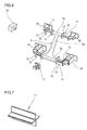
- FIG. 6 is a perspective view to show a collision test apparatus using a test sample support of the present embodiment.
- FIG. 7 is a perspective view to show a main body of the test sample support shown in FIG. 6.
- FIGS. 6 and 7 as well as FIGS. 3 and 4 , exemplify a case in which collision test is performed on the center pillar assembly 5 as the test sample, in which overlapping description will be conveniently omitted.
- the test sample support 10 includes a linear main body 11, a first attachment part 12, and a second attachment part 13.
- the cross section of the main body 11 of the test sample support 10 is an open section whose circumference is opened.
- the cross section of the main body 11 is cross-shaped, and made up of two equilateral angle steels having an L-shape. Specifically, corner portions of the equilateral angle steels are butt welded over the entire region in the longitudinal direction, thereby joining them together.
- the first attachment part 12 is connected by welding to one end of both ends of the main body 11.
- the second attachment part 13 is connected by welding to the other end of both ends of the main body 11.
- These first attachment part 12 and second attachment part 13 are, for example, flat steels.
- the test sample support 10 is secured to a supporting point of the center pillar assembly 5. Specifically, the test sample support 10 is disposed at each of total of 4 locations including the front end and rear end of the lower horizontal part 5b, and the front end and rear end of the upper horizontal part 5c of the center pillar assembly 5.
- the first attachment part 12 of the test sample support 10 is secured by welding to each of the front end and rear end of the lower horizontal part 5b and to each of the front end and rear end of the upper horizontal part 5c.
- the connector 16 is formed, for example, by combining a plurality of flat steels, angle steels, or the like and joining them by welding or a bolt, and is a rigid body which is hardly plastically deformed.
- the connector 16 and the rigid wall are detachably connected by a bolt.
- the material of the test sample support 10 will not be particularly limited, provided that it is a metal.
- the material of the test sample support 10 is preferably a carbon steel.
- each test sample support 10 is disposed in an orientation to extend in the fore-and-aft direction. Then, when performing a collision test, an impact is applied to the pillar part 5a from its side by an impactor 17 which moves in the horizontal direction.
- the impactor 17 is attached to a carriage (not shown), and applies an impact load, which corresponds to a side collision in a real-vehicle test, to the pillar part 5a.
- the carriage is equipped with a measuring instrument such as a load cell and a displacement meter.
- deformation behavior of the entire pillar part 5a is observed by moving image photographing with a camera 18.
- a load (reactive force) acting on the impactor 17 and an intruding amount of the impactor 17 are measured by the above described measurement instrument. Note that when photographing with the camera 18, the pillar part 5a to be photographed is illuminated by an illumination device.
- FIG. 8 is a stress analysis diagram to show a deformed state of the test sample support when the collision test apparatus of the present embodiment is adopted.
- the test sample support 10 of the present embodiment that is, a test sample support 10 whose cross section is an open section as shown in FIG. 7
- torsional deformation and bending deformation occur caused by an impact load during collision test as in an actual real-vehicle test, as shown in FIG. 8 .
- uniform plastic deformation occurs without occurrence of buckling. For this reason, the results obtained by the collision test will be stable.
- test sample support of the present embodiment since the test sample support has an appropriate torsional rigidity and bending rigidity, the deformation behavior of a structural member (for example, a center pillar assembly), which is the test sample, becomes equivalent to that in a real-vehicle test. Therefore, it becomes possible to accurately evaluate the side collision performance of a structural member.
- the test sample support of the present embodiment can be easily fabricated since the cross section of its main body is a simple open section. Therefore, it becomes possible to perform collision test conveniently and at a low cost.
- the collision test of the present embodiment does not use a flywheel as the test sample support as in Patent Literature 1, it is possible to ensure a sufficient field of view of the camera for photographing the deformation behavior of the test sample.
- the test sample support 10 of the present embodiment can take various forms as long as the cross section of the main body 11 is an open section.
- the cross sectional shape of the main body 11 will not be limited to a cross-shape, but may be a U-shape, an L-shape, a T-shape, or the like.
- the main body 11 may be formed by combining a plurality of angle steels, or by using a single angle steel. When a plurality of angle steels are combined, the joining method thereof may either be welding, or fastening by a bolt.
- the angle steel to be adopted in this case is, for example, an equilateral angle steel, an inequilateral angle steel, a channel steel, a T-shaped steel, and the like.
- the angle steel is, for example, an equilateral angle steel, an inequilateral angle steel, a channel steel, an H-shaped steel, an I-shaped steel, a T-shaped steel, and the like. Any of the angle steels is a general purpose product, which can be easily procured.
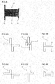
- FIGS. 9A to 9F are each a cross sectional view to show a variant of the test sample support of the present embodiment.
- the main body 11 shown in FIG. 9A corresponds to that shown in FIG. 7 .
- the main body 11 has a cross section of cross-shape, and is formed by joining by welding two equilateral angle steels to each other.
- the main bodies 11 shown in FIGS. 9B to 9D each have a cross section of cross shape, and is made up of two inequilateral angle steels. Among these, the main body 11 shown in FIG. 9B is formed by joining angle steels to each other by a bolt. The main bodies 11 shown in FIGS. 9C and 9D are each formed by joining by welding angle steels to each other. In these cases, torsional rigidity is not variable, and only bending rigidity can be adjustable.
- the main body 11 shown in FIG. 9E has a cross section of H-shape, and is formed by joining by welding two channel steels to each other.
- the main body 11 shown in FIG. 9F has a cross section of I-shape, and is one made up of a single I-shaped steel.
- the test sample support 10 of the present invention can easily adjust its rigidity.
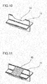
- forming a gradually varied section 14 in a part of the angle steel constituting the main body 11 of the test sample support 10 can appropriately reduce the rigidity of the test sample support 10.
- the gradually varied section 14 means a shape (for example, a concave part) which is not uniform, but is gradually varied.
- attaching by welding a steel sheet 15 to the circumference of the angle steel that constitutes the main body 11 of the test sample support 10 can appropriately enhance the rigidity of the test sample support 10.
- the attaching region of the steel sheet 15 may be all or a part of the circumference of the main body 11.
- adjusting the dimensions of the main body 11, particularly its longitudinal dimension can adjust the rigidity of the test sample support 10.
- the adjustment amounts of dimension and shape, and rigidity of the test sample support are set, for example, in the following way.
- a CAE Computer Aided Engineering
- the deformation properties of structural members around the test sample are acquired by the CAE analysis. For example, when the test sample is a center pillar assembly, the properties of torsional deformation and bending deformation of the side sill and the roof rail are acquired. Then, based on the deformation properties, the adjustment amounts of dimension and shape, and rigidity of the test sample support 10 are set.
- the above described embodiment shows an example in which a center pillar assembly is selected as the structural member to be the test sample.
- the structural member to be the test sample is not limited to the center pillar assembly.
- the test sample may be a side sill, a roof rail, or the like.
- a center pillar assembly was supported by using the test sample support having an open section as shown in FIGS. 6 and 7 , and a side collision test was conducted.
- a center pillar assembly was supported by using the test sample support having a closed section as shown in FIGS. 3 and 4 , and a side collision test was conducted.
- a real-vehicle test was conducted. All of the tests were conducted conforming to the specifications of SUV SIDE IMPACT of IIHS (Insurance Institute for Highway Safety). A reactive force acting on the impactor, and an intruding amount of the impactor were investigated during the course of the impactor intruding into the center pillar assembly during a test.
- FIG. 12 is a diagram to show a relationship between intruding amount of an impactor and reactive force to the impactor as a test result of an example.
- FIG. 12 in the test of the inventive example of the present invention which used the test sample support having an open section, a result similar to that in the real-vehicle test was obtained.
- the test of the reference example which used the test sample support having a closed section it is revealed that the reactive force to the impactor decreased in a final stage of the intrusion of the impactor, thus deviating from the result of the real-vehicle test. This is caused by the fact that buckling occurred in the test sample support.
- the present invention can be effectively used for evaluating the collision performance of structural members constituting an automobile body.
Landscapes
- Physics & Mathematics (AREA)
- General Physics & Mathematics (AREA)
- Engineering & Computer Science (AREA)
- Chemical & Material Sciences (AREA)
- Combustion & Propulsion (AREA)
- Transportation (AREA)
- Mechanical Engineering (AREA)
- Investigating Strength Of Materials By Application Of Mechanical Stress (AREA)
- Vibration Dampers (AREA)
Abstract
Description
- The present invention relates to a collision test for evaluating a side collision performance of various structural members constituting a body of an automobile. Particularly, the present invention relates to a test sample support which supports a structural member as a test sample, and is used for a collision test of the structural member, and a collision test apparatus and a collision test method of the structural member by using the aforementioned support.
-
FIG. 1 is a perspective view to show a body of an automobile. The body of an automobile includes various structural members. For example, when an automobile is subjected to a side collision, an injury value of an occupant largely depends on deformation behaviors of a center pillar 1, aside sill 2, and aroof rail 3 among the structural members. The center pillar 1 is disposed in an upright orientation at each of both sides of the body. Theside sill 2 is connected to a lower end of the center pillar 1. Theroof rail 3 is connected to an upper end of the center pillar 1. Theside sill 2 and theroof rail 3 extend in the fore-and-aft direction of the body. - In the development of an automobile, it is essential to evaluate the performance of structural members against side collision. In general, automobile manufacturers fabricate a proto-type vehicle and performs a side collision test by using the proto-type vehicle (hereafter, also referred to as a "real-vehicle test") to evaluate the performance of the structural members. However, such a proto-type vehicle is costly, and the fabrication time of the proto-type vehicle is long. For that reason, chances of performing such evaluation by a real-vehicle test are limited. Moreover, when a problem occurs in the performance of a structural member in a real-vehicle test, it becomes necessary to fabricate another proto-type vehicle of a modified design and perform the real-vehicle test again, causing the automobile development to be delayed. Particularly, since the period of automobile development has been shortened in recent years, it is difficult to perform real-vehicle tests at many conditions. Therefore, it is also not easy to adopt a new material, a new structure, and like for the structural members.
- Further, it is difficult for material manufacturers (for example, steel manufacturers), parts manufacturers, and the like other than automobile manufacturers to perform a real-vehicle test independently. This is because there are constraints in the preparation of proto-type vehicles, the construction of real-vehicle test facilities, and the like. For that reason, it is very difficult for a manufacturer of starting material, a manufacturer of parts, or the like to evaluate the collision performance of its own product.
- Therefore, it is particularly desirable to perform a collision test by using a single structural member without performing a real-vehicle test which uses a proto-type vehicle, as a technique for evaluating the performance of a structural member against side collision.
- For example, Japanese Patent Publication No.
4902027 -
FIG. 2 is a side view to show a collision test apparatus disclosed in Patent Literature 1. As shown inFIG. 2 , in a collision test of Patent Literature 1, acenter pillar assembly 5 among structural members is used as the test sample. Thecenter pillar assembly 5 includes apillar part 5a, a lowerhorizontal part 5b which extends from a lower end of thepillar part 5a in a fore-and-aft direction, and an upperhorizontal part 5c which extends from an upper end of thepillar part 5a in the fore-and-aft direction. Thecenter pillar assembly 5 is supported at a total of four portions including the front end and rear end of the lowerhorizontal part 5b and the front end and rear end of the upperhorizontal part 5c via aflywheel 104, respectively. During the collision test, an impact is applied to thepillar part 5a by animpactor 17 which moves in the horizontal direction. Theflywheel 104 serves to simulate deformation resistance of theside sill 2 and theroof rail 3 when subjected to an impact load, and reproduces deformation behavior of the center pillar 1 similar to that in a real-vehicle test. - In reality, however, upon a side collision in a real-vehicle test, the
side sill 2 and theroof rail 3 undergo torsional deformation and bending deformation at the same time as thepillar part 5a undergoes bending deformation. In other words, theside sill 2 and theroof rail 3 undergo plastic deformation. In this respect, in the technique of Patent Literature 1, theflywheel 104 which simulates theside sill 2 and theroof rail 3 allows rotation and does not undergo plastic deformation. For that reason, there is a risk that results obtained from the collision test of Patent Literature 1 deviate from results of a real-vehicle test. - Moreover, the technique of Patent Literature 1 is laborious in assembling the
center pillar assembly 5 to the test apparatus. Further, during a collision test of Patent Literature 1, the deformation behavior of thepillar part 5a is observed by a camera (not shown). In that occasion, theflywheel 104 hinders the photographing by the camera. - Patent Literature 1: Japanese Patent Publication No.
4902027 - The present invention has been made in view of the above described problems. An object of the present invention is to provide a test sample support, and a collision test apparatus and a collision test method of the structural member by using the support, which have the following features, relating to a collision test using a structural member of an automobile body as a test sample:
- collision test can be performed conveniently and at a low cost; and
- side collision performance of a structural member can be accurately evaluated.
- A test sample support according to an embodiment of the present invention is a test sample support for use in a collision test using a structural member of an automobile body as a test sample.
- The test sample support includes:
- a linear main body,
- a first attachment part to be connected by welding to one end of both ends of the main body and adapted to be secured to the structural member, and
- a second attachment part to be connected by welding to another end of the both ends and adapted to be secured to a collision test apparatus, wherein
- In the above described test sample support, the cross section of the main body is preferably cross-shaped. In this case, the main body is preferably made up of two equilateral angle steels which are joined by welding to each other.
- In the above described test sample support, the main body can be made up of a plurality of angle steels which are joined by welding or a bolt to one another. In this case, the angle steel is preferably an equilateral angle steel, an inequilateral angle steel, a channel steel, or a T-shaped steel.
- In the above described test sample support, the main body can be made up of a single angle steel. In this case, the angle steel is preferably an equilateral angle steel, an inequilateral angle steel, a channel steel, an H-shaped steel, an I-shaped steel, or a T-shaped steel.
- In the above described test sample support, a steel sheet may be joined by welding to all or a part of the circumference of the main body.
- In the above described test sample support, a gradually varied section may be formed in a part of the main body.
- A collision test apparatus according to an embodiment of the present invention is a collision test apparatus using a structural member of an automobile body as a test sample.
- The first attachment part of the above described test sample support is secured to each of both ends of the structural member.
- The collision test apparatus includes:
- a rigid wall to which the second attachment part of each test sample support is secured;
- an impactor for applying impact to the structural member from its side;
- a camera for observing deformation behavior of the structural member; and
- a measurement instrument for measuring a load acting on the impactor and a displacement of the impactor.
- The above described collision test apparatus preferably includes a connector between the second attachment part of the test sample support and the rigid wall.
- In the above described collision test apparatus, the structural member is a center pillar assembly and is preferably disposed in an upright orientation.
- A collision test method according to an embodiment of the present invention is a collision test method in which a test sample is a structural member of an automobile body.
- The collision test method includes steps of:
- securing the first attachment part of the test sample support to each of both ends of the structural member;
- securing the second attachment part of each test sample support; and
- applying impact on the structural member from its side to observe deformation behavior of the structural member, and measuring a load acting on the impactor and a displacement of the impactor.
- A test sample support, and a collision test apparatus and a collision test method of a structural member using the support of the present invention have the following notable effects:
- collision test can be performed conveniently and at a low cost; and
- side collision performance of a structural member can be accurately evaluated.
-
- [
FIG. 1] FIG.1 is a perspective view to show a body of an automobile. - [
FIG. 2] FIG. 2 is a side view to show a collision test apparatus disclosed in Patent Literature 1. - [
FIG. 3] FIG. 3 is a perspective view to show a collision test apparatus using a test sample support whose cross section is a closed section. - [
FIG. 4] FIG. 4 is a perspective view to show a main body of the test sample support shown inFIG. 3 . - [
FIG. 5] FIG. 5 is a stress analysis diagram to show a deformed state of the test sample support when the collision test apparatus shown inFIG. 3 is adopted. - [
FIG. 6] FIG. 6 is a perspective view to show a collision test apparatus using a test sample support of the present embodiment. - [
FIG. 7] FIG. 7 is a perspective view to show a main body of the test sample support shown inFIG. 6 . - [
FIG. 8] FIG. 8 is a stress analysis diagram to show a deformed state of the test sample support when the collision test apparatus of the present embodiment is adopted. - [
FIG. 9A] FIG. 9A is a cross sectional view to show a variant of the test sample support of the present embodiment. - [
FIG. 9B] FIG. 9B is a cross sectional view to show a variant of the test sample support of the present embodiment. - [
FIG. 9C] FIG. 9C is a cross sectional view to show a variant of the test sample support of the present embodiment. - [
FIG. 9D] FIG. 9D is a cross sectional view to show a variant of the test sample support of the present embodiment. - [
FIG. 9E] FIG. 9E is a cross sectional view to show a variant of the test sample support of the present embodiment. - [
FIG. 9F] FIG. 9F is a cross sectional view to show a variant of the test sample support of the present embodiment. - [
FIG. 10] FIG. 10 is a perspective view to show a variant of the test sample support of the present embodiment. - [
FIG. 11] FIG. 11 is a perspective view to show a variant of the test sample support of the present embodiment. - [
FIG. 12] FIG. 12 is a diagram to show a relationship between intruding amount of an impactor and reactive force to the impactor as a test result of an example. - As described above, in the collision test in Patent Literature 1, the test sample support which is used to support a center pillar assembly which is the test sample, is a flywheel which simulates a side sill and a roof rail. This flywheel does not undergo plastic deformation during the collision test. On the other hand, in an actual real-vehicle test, the side sill and the roof rail undergo torsional deformation, and bending deformation at the same time. In conclusion, the situation of the collision test in Patent Literature 1 is different from that of a real-vehicle test. Accordingly, the present inventors have conducted an intensive study on a convenient test sample support which can replace the flywheel used in the collision test in Patent Literature 1.
- Properties required of the test sample support are, for example, deformation properties (torsional deformation and bending deformation) of the side sill and the roof rail when the test sample is a center pillar assembly. In conclusion, appropriate torsional rigidity and bending rigidity are demanded of the test sample support. As a test sample support to satisfy such properties, the present inventors first conducted a study on those test sample supports each of whose cross section is a closed section.
-
FIG. 3 is a perspective view to show a collision test apparatus using a test sample support whose cross section is a closed section.FIG. 4 is a perspective view to show a main body of the test sample support shown inFIG. 3. FIGS. 3 and 4 exemplify a case in which collision test is performed on acenter pillar assembly 5 as a test sample. - As shown in
FIG. 3 , thecenter pillar assembly 5 includes apillar part 5a, a lowerhorizontal part 5b, and an upperhorizontal part 5c. Thepillar part 5a corresponds to the center pillar 1 shown inFIG. 1 . The lowerhorizontal part 5b extends from a lower end of thepillar part 5a in the fore-and-aft direction thereof, and constitutes a part of theside sill 2 shown inFIG. 1 . The upperhorizontal part 5c extends from an upper end of thepillar part 5a in the fore-and-aft direction thereof, and constitutes a part of aroof rail 3. - A test sample support 110 includes a linear main body 111, a first attachment part 112, and a second attachment part 113. The main body 111 of the test sample support 110 is formed by combining two press formed products having a hat-shaped cross section and joining them together by welding as shown in
FIG. 4 . The cross section of the main body 111 is a closed section whose circumference is closed. The first attachment part 112 is connected by welding to one end of both ends of the main body 111. The second attachment part 113 is connected by welding to the other end of both ends of the main body 111. - The test sample support 110 is secured to a supporting point of the
center pillar assembly 5. Specifically, the test sample support 110 is disposed at each of total of 4 locations including the front end and rear end of the lowerhorizontal part 5b, and the front end and rear end of the upperhorizontal part 5c of thecenter pillar assembly 5. The first attachment part 112 of each test sample support 110 is secured by welding to each of the front end and rear end of the lowerhorizontal part 5b and to each of the front end and rear end of the upperhorizontal part 5c. - The
center pillar assembly 5 to which the test sample supports 110 have been attached is secured to the collision test apparatus (not shown) with thepillar part 5a being kept in an upright orientation. Specifically, the second attachment part 113 of each test sample support 110 is secured to the rigid wall (not shown) of the collision test apparatus via aconnector 16. - In a state that the
center pillar assembly 5 is secured to the collision test apparatus, the main body 111 of each test sample support 110 is disposed in an orientation to extend in the fore-and-aft direction. Then, when performing a collision test, an impact is applied to thepillar part 5a from its side by an impactor (not shown) which moves in the horizontal direction. -
FIG. 5 is a stress analysis diagram to show a deformed state of the test sample support when the collision test apparatus shown inFIG. 3 is adopted. In a case of the test sample support 110 whose cross section is a closed section, that is, a test sample support 110 which is formed by joining by welding two press formed products each having a hat-shaped cross section as shown inFIG. 4 , torsional deformation and bending deformation occur caused by an impact load during collision test as in an actual real-vehicle test, as shown inFIG. 5 . However, in this case, as obvious from the stress distribution shown by light and shade inFIG. 5 , a top plate part and a vertical wall part of the test sample support 110 undergo plastic deformation in an irregular manner while being buckled. For this reason, variations are likely to occur in the results obtained by the collision test. - Therefore, it cannot be said that a collision test using a test sample support 110 whose cross section is a closed section is sufficient to accurately evaluate the side collision performance of a structural member.
- The present inventors have conducted further studies in consideration of the above described matters, to complete the present invention. Hereafter, embodiments will be described in detail regarding the test sample support of the present invention, and the collision test apparatus and collision test method of a structural member by using the aforementioned support.
-
FIG. 6 is a perspective view to show a collision test apparatus using a test sample support of the present embodiment.FIG. 7 is a perspective view to show a main body of the test sample support shown inFIG. 6. FIGS. 6 and 7 , as well asFIGS. 3 and 4 , exemplify a case in which collision test is performed on thecenter pillar assembly 5 as the test sample, in which overlapping description will be conveniently omitted. - The
test sample support 10 includes a linearmain body 11, afirst attachment part 12, and asecond attachment part 13. The cross section of themain body 11 of thetest sample support 10 is an open section whose circumference is opened. The cross section of themain body 11 is cross-shaped, and made up of two equilateral angle steels having an L-shape. Specifically, corner portions of the equilateral angle steels are butt welded over the entire region in the longitudinal direction, thereby joining them together. - The
first attachment part 12 is connected by welding to one end of both ends of themain body 11. Thesecond attachment part 13 is connected by welding to the other end of both ends of themain body 11. Thesefirst attachment part 12 andsecond attachment part 13 are, for example, flat steels. - The
test sample support 10 is secured to a supporting point of thecenter pillar assembly 5. Specifically, thetest sample support 10 is disposed at each of total of 4 locations including the front end and rear end of the lowerhorizontal part 5b, and the front end and rear end of the upperhorizontal part 5c of thecenter pillar assembly 5. Thefirst attachment part 12 of thetest sample support 10 is secured by welding to each of the front end and rear end of the lowerhorizontal part 5b and to each of the front end and rear end of the upperhorizontal part 5c. - The
center pillar assembly 5 to which the test sample supports 10 have been attached is secured to the collision test apparatus (not shown) with thepillar part 5a being kept in an upright orientation. Specifically, thesecond attachment part 13 of eachtest sample support 10 is secured to a rigid wall (not shown) of the collision test apparatus.FIG. 6 exemplifies a case in which thesecond attachment part 13 of eachtest sample support 10 is secured to the rigid wall via theconnector 16. The rigid wall is a complete rigid body made of cast steel and secured to the ground. Thesecond attachment part 13 of eachtest sample support 10 and theconnector 16 are connected to each other by welding or a bolt. Theconnector 16 is formed, for example, by combining a plurality of flat steels, angle steels, or the like and joining them by welding or a bolt, and is a rigid body which is hardly plastically deformed. Theconnector 16 and the rigid wall are detachably connected by a bolt. - The material of the
test sample support 10 will not be particularly limited, provided that it is a metal. The material of thetest sample support 10 is preferably a carbon steel. - In a state in which the
center pillar assembly 5 is secured to the collision test apparatus, themain body 11 of eachtest sample support 10 is disposed in an orientation to extend in the fore-and-aft direction. Then, when performing a collision test, an impact is applied to thepillar part 5a from its side by an impactor 17 which moves in the horizontal direction. The impactor 17 is attached to a carriage (not shown), and applies an impact load, which corresponds to a side collision in a real-vehicle test, to thepillar part 5a. The carriage is equipped with a measuring instrument such as a load cell and a displacement meter. Moreover, during a collision test, deformation behavior of theentire pillar part 5a is observed by moving image photographing with a camera 18. Further, in the course of the impactor 17 intruding into thecenter pillar assembly 5, a load (reactive force) acting on the impactor 17 and an intruding amount of the impactor 17 are measured by the above described measurement instrument. Note that when photographing with the camera 18, thepillar part 5a to be photographed is illuminated by an illumination device. -
FIG. 8 is a stress analysis diagram to show a deformed state of the test sample support when the collision test apparatus of the present embodiment is adopted. In a case of thetest sample support 10 of the present embodiment, that is, atest sample support 10 whose cross section is an open section as shown inFIG. 7 , torsional deformation and bending deformation occur caused by an impact load during collision test as in an actual real-vehicle test, as shown inFIG. 8 . Moreover, in this case, as obvious from the stress distribution shown by light and shade inFIG. 8 , uniform plastic deformation occurs without occurrence of buckling. For this reason, the results obtained by the collision test will be stable. - In this way, according to a collision test by use of a test sample support of the present embodiment, since the test sample support has an appropriate torsional rigidity and bending rigidity, the deformation behavior of a structural member (for example, a center pillar assembly), which is the test sample, becomes equivalent to that in a real-vehicle test. Therefore, it becomes possible to accurately evaluate the side collision performance of a structural member. Moreover, the test sample support of the present embodiment can be easily fabricated since the cross section of its main body is a simple open section. Therefore, it becomes possible to perform collision test conveniently and at a low cost. Moreover, since the collision test of the present embodiment does not use a flywheel as the test sample support as in Patent Literature 1, it is possible to ensure a sufficient field of view of the camera for photographing the deformation behavior of the test sample.
- The
test sample support 10 of the present embodiment can take various forms as long as the cross section of themain body 11 is an open section. For example, the cross sectional shape of themain body 11 will not be limited to a cross-shape, but may be a U-shape, an L-shape, a T-shape, or the like. Moreover, themain body 11 may be formed by combining a plurality of angle steels, or by using a single angle steel. When a plurality of angle steels are combined, the joining method thereof may either be welding, or fastening by a bolt. The angle steel to be adopted in this case is, for example, an equilateral angle steel, an inequilateral angle steel, a channel steel, a T-shaped steel, and the like. On the other hand, when a single angle steel is used, the angle steel is, for example, an equilateral angle steel, an inequilateral angle steel, a channel steel, an H-shaped steel, an I-shaped steel, a T-shaped steel, and the like. Any of the angle steels is a general purpose product, which can be easily procured. -
FIGS. 9A to 9F are each a cross sectional view to show a variant of the test sample support of the present embodiment. Themain body 11 shown inFIG. 9A corresponds to that shown inFIG. 7 . In other words, themain body 11 has a cross section of cross-shape, and is formed by joining by welding two equilateral angle steels to each other. - The
main bodies 11 shown inFIGS. 9B to 9D each have a cross section of cross shape, and is made up of two inequilateral angle steels. Among these, themain body 11 shown inFIG. 9B is formed by joining angle steels to each other by a bolt. Themain bodies 11 shown inFIGS. 9C and 9D are each formed by joining by welding angle steels to each other. In these cases, torsional rigidity is not variable, and only bending rigidity can be adjustable. - The
main body 11 shown inFIG. 9E has a cross section of H-shape, and is formed by joining by welding two channel steels to each other. Themain body 11 shown inFIG. 9F has a cross section of I-shape, and is one made up of a single I-shaped steel. - Moreover, the
test sample support 10 of the present invention can easily adjust its rigidity. For example, as shown inFIG. 10 , forming a graduallyvaried section 14 in a part of the angle steel constituting themain body 11 of thetest sample support 10 can appropriately reduce the rigidity of thetest sample support 10. The graduallyvaried section 14 means a shape (for example, a concave part) which is not uniform, but is gradually varied. Moreover, as shown inFIG. 11 , attaching by welding asteel sheet 15 to the circumference of the angle steel that constitutes themain body 11 of thetest sample support 10 can appropriately enhance the rigidity of thetest sample support 10. The attaching region of thesteel sheet 15 may be all or a part of the circumference of themain body 11. In addition to these, adjusting the dimensions of themain body 11, particularly its longitudinal dimension can adjust the rigidity of thetest sample support 10. - The adjustment amounts of dimension and shape, and rigidity of the test sample support are set, for example, in the following way. A CAE (Computer Aided Engineering) analysis is performed in advance on a structural member to be the test sample, and structural members around that structural member. The deformation properties of structural members around the test sample are acquired by the CAE analysis. For example, when the test sample is a center pillar assembly, the properties of torsional deformation and bending deformation of the side sill and the roof rail are acquired. Then, based on the deformation properties, the adjustment amounts of dimension and shape, and rigidity of the
test sample support 10 are set. - The above described embodiment shows an example in which a center pillar assembly is selected as the structural member to be the test sample. However, the structural member to be the test sample is not limited to the center pillar assembly. The test sample may be a side sill, a roof rail, or the like.
- In order to confirm effects of the present invention, the following tests were performed. As an inventive example of the present invention, a center pillar assembly was supported by using the test sample support having an open section as shown in
FIGS. 6 and 7 , and a side collision test was conducted. As a reference example of the present invention, a center pillar assembly was supported by using the test sample support having a closed section as shown inFIGS. 3 and 4 , and a side collision test was conducted. Moreover, for a comparison purpose, a real-vehicle test was conducted. All of the tests were conducted conforming to the specifications of SUV SIDE IMPACT of IIHS (Insurance Institute for Highway Safety). A reactive force acting on the impactor, and an intruding amount of the impactor were investigated during the course of the impactor intruding into the center pillar assembly during a test. -
FIG. 12 is a diagram to show a relationship between intruding amount of an impactor and reactive force to the impactor as a test result of an example. As shown inFIG. 12 , in the test of the inventive example of the present invention which used the test sample support having an open section, a result similar to that in the real-vehicle test was obtained. In contrast to this, in the test of the reference example which used the test sample support having a closed section, it is revealed that the reactive force to the impactor decreased in a final stage of the intrusion of the impactor, thus deviating from the result of the real-vehicle test. This is caused by the fact that buckling occurred in the test sample support. - The present invention can be effectively used for evaluating the collision performance of structural members constituting an automobile body.
-
- 1:
- Center pillar
- 2:
- Side sill
- 3:
- Roof rail
- 5:
- Center pillar assembly
- 5a:
- Pillar part
- 5b:
- Lower horizontal part
- 5c:
- Upper horizontal part
- 10:
- Test sample support
- 11:
- Main body
- 12:
- First attachment part
- 13:
- Second attachment part
- 14:
- Gradually varied section
- 15:
- Steel sheet
- 16:
- Connector
- 17:
- Impactor
- 18:
- Camera
Claims (13)
- A test sample support for use in a collision test using a structural member of an automobile body as a test sample, the test sample support comprising:a linear main body;a first attachment part to be connected by welding to one end of both ends of the main body and adapted to be secured to the structural member; anda second attachment part to be connected by welding to another end of the both ends and adapted to be secured to a collision test apparatus, whereina cross section of the main body is an open section.
- The test sample support according to claim 1, wherein
the cross section of the main body is cross-shaped. - The test sample support according to claim 2, wherein
the main body is made up of two equilateral angle steels which are joined by welding to each other. - The test sample support according to claim 1, wherein
the main body is made up of a plurality of angle steels which are joined by welding or a bolt to one another. - The test sample support according to claim 4, wherein
the angle steel is an equilateral angle steel, an inequilateral angle steel, a channel steel, or a T-shaped steel. - The test sample support according to claim 1, wherein
the main body is made up of a single angle steel. - The test sample support according to claim 6, wherein
the angle steel is an equilateral angle steel, an inequilateral angle steel, a channel steel, an H-shaped steel, an I-shaped steel, or a T-shaped steel. - The test sample support according to any one of claims 1 to 7, wherein
a steel sheet is joined by welding to all or a part of a circumference of the main body. - The test sample support according to any one of claims 1 to 8, wherein
a gradually varied section is formed in a part of the main body. - A collision test apparatus using a structural member of an automobile body as a test sample, the first attachment part of the test sample support according to any one of claims 1 to 9 is secured to each of both ends of the structural member,
the collision test apparatus comprises:a rigid wall to which the second attachment part of each test sample support is secured;an impactor for applying impact to the structural member from its side;a camera for observing deformation behavior of the structural member; anda measurement instrument for measuring a load acting on the impactor and a displacement of the impactor. - The collision test apparatus according to claim 10, wherein
the collision test apparatus comprises a connector between the second attachment part of the test sample support and the rigid wall. - The collision test apparatus according to claim 10 or 11, wherein
the structural member is a center pillar assembly and is disposed in an upright orientation. - A collision test method in which a test sample is a structural member of an automobile body,
the collision test method includes steps of:securing the first attachment part of the test sample support according to any one of claims 1 to 9 to each of both ends of the structural member;securing the second attachment part of each test sample support; andapplying impact on the structural member from its side to observe deformation behavior of the structural member, and measuring a load acting on the impactor and a displacement of the impactor.
Applications Claiming Priority (2)
| Application Number | Priority Date | Filing Date | Title |
|---|---|---|---|
| JP2013252189 | 2013-12-05 | ||
| PCT/JP2014/006032 WO2015083376A1 (en) | 2013-12-05 | 2014-12-03 | Test body support tool, and crash test device and crash test method for structural member that use said support tool |
Publications (4)
| Publication Number | Publication Date |
|---|---|
| EP3078955A1 true EP3078955A1 (en) | 2016-10-12 |
| EP3078955A4 EP3078955A4 (en) | 2017-10-25 |
| EP3078955B1 EP3078955B1 (en) | 2019-05-15 |
| EP3078955B8 EP3078955B8 (en) | 2019-07-31 |
Family
ID=53273159
Family Applications (1)
| Application Number | Title | Priority Date | Filing Date |
|---|---|---|---|
| EP14867549.9A Active EP3078955B8 (en) | 2013-12-05 | 2014-12-03 | Test body support tool, and crash test device and crash test method for structural member that use said support tool |
Country Status (7)
| Country | Link |
|---|---|
| US (1) | US10753826B2 (en) |
| EP (1) | EP3078955B8 (en) |
| JP (1) | JP6070862B2 (en) |
| KR (1) | KR101906691B1 (en) |
| CN (1) | CN105814422B (en) |
| TR (1) | TR201907737T4 (en) |
| WO (1) | WO2015083376A1 (en) |
Families Citing this family (10)
| Publication number | Priority date | Publication date | Assignee | Title |
|---|---|---|---|---|
| KR101927051B1 (en) * | 2016-12-29 | 2018-12-10 | 주식회사 신영 | A Testing Jig and Crash Test For Center Pillar That Use Said Testing Jig |
| KR101865864B1 (en) * | 2017-04-28 | 2018-06-08 | (주)세원물산 | Apparatus for testing a car center pillar |
| CN107084827B (en) * | 2017-05-11 | 2019-06-28 | 象山华鹰塑料工程有限公司 | A kind of automotive trim plastic parts impact strength detection device |
| JP6706015B1 (en) | 2018-09-27 | 2020-06-03 | Jfeスチール株式会社 | Crash performance evaluation test method and device for automobile body parts |
| JP6729778B1 (en) | 2019-06-07 | 2020-07-22 | Jfeスチール株式会社 | Side collision test apparatus for center pillar of automobile and method for determining test condition in side collision test of center pillar using the side collision test apparatus |
| JP7360146B2 (en) * | 2019-08-01 | 2023-10-12 | 有限会社多久和 | Test jig |
| CN114245865B (en) * | 2019-09-26 | 2024-04-05 | 杰富意钢铁株式会社 | Method and device for evaluating and testing collision performance of automobile body part |
| JP7389345B2 (en) * | 2020-02-04 | 2023-11-30 | 日本製鉄株式会社 | Test specimen support |
| JP7167960B2 (en) * | 2020-04-07 | 2022-11-09 | Jfeスチール株式会社 | Frontal collision test method for vehicle body side structure |
| CN111623947A (en) * | 2020-04-22 | 2020-09-04 | 南京蜂动检测科技有限公司 | Method for detecting safety performance of automobile parts |
Family Cites Families (24)
| Publication number | Priority date | Publication date | Assignee | Title |
|---|---|---|---|---|
| US1013649A (en) * | 1903-09-14 | 1912-01-02 | American Universal Mill Company | Solid rolled metal i-beam of nine inches and under twelve inches in height. |
| JPS492027B1 (en) | 1970-07-31 | 1974-01-18 | ||
| JP2772401B2 (en) * | 1989-08-03 | 1998-07-02 | 日産自動車株式会社 | How to determine the position of the collapsed bead |
| KR100195994B1 (en) | 1996-09-23 | 1999-06-15 | 류정열 | Jig for estimation hardness b-piller part of a car body |
| US6178805B1 (en) * | 1997-07-22 | 2001-01-30 | Chrysler Corporation | Method and apparatus for side impact testing of motor vehicles at a sub-system level |
| JPH11208504A (en) * | 1998-01-30 | 1999-08-03 | Isuzu Motors Ltd | Body frame reinforcement structure |
| JP2003200287A (en) * | 2001-12-27 | 2003-07-15 | Daiwa House Ind Co Ltd | Welding method of not producing strain in metallic plate |
| JP2006281964A (en) * | 2005-03-31 | 2006-10-19 | Kobe Steel Ltd | Automobile center pillar and method for evaluating performance of upper part buckling property proof of automobile center pillar |
| JP4785493B2 (en) * | 2005-10-24 | 2011-10-05 | アイシン高丘株式会社 | Collision reinforcing material for vehicle and manufacturing method thereof |
| JP2007261469A (en) * | 2006-03-29 | 2007-10-11 | Toray Ind Inc | Impact energy absorber |
| JP4562677B2 (en) * | 2006-03-30 | 2010-10-13 | 株式会社神戸製鋼所 | Welded structure closed section frame |
| FR2915451B1 (en) * | 2007-04-26 | 2009-10-09 | Vallourec Vitry | PROLONGED WITH PERFECTED SUPPORT. |
| JP4445522B2 (en) * | 2007-06-20 | 2010-04-07 | 豊田鉄工株式会社 | Reinforcing member for vehicle center pillar |
| ES2303804B1 (en) * | 2008-02-25 | 2009-03-16 | Fundacion Cidaut | TEST SYSTEM OF THE PILLARS OF A VEHICLE BEFORE A SIDE COLLISION. |
| ES2303806B1 (en) * | 2008-03-17 | 2009-05-05 | Fundacion Cidaut | TEST SYSTEM OF THE DOORS OF A VEHICLE BEFORE A SIDE COLLISION AND ADJUSTMENT PROCEDURE. |
| CN101551293A (en) | 2009-04-09 | 2009-10-07 | 上海交通大学 | Simulated collision test device and test method thereof |
| KR101454140B1 (en) | 2009-08-04 | 2014-10-22 | 신닛테츠스미킨 카부시키카이샤 | Method for evaluating collision performance of vehicle member, and member collision test device used for same |
| JP5126411B2 (en) * | 2010-04-09 | 2013-01-23 | トヨタ自動車株式会社 | Vehicle side joint structure |
| JP2011240788A (en) * | 2010-05-17 | 2011-12-01 | Toyota Motor Corp | Structure of connection part in vehicle side part |
| CN102803024B (en) | 2011-03-24 | 2015-03-04 | 爱信高丘株式会社 | Collision reinforcement material for vehicle |
| JP5246300B2 (en) * | 2011-06-14 | 2013-07-24 | Jfeスチール株式会社 | Body side structure |
| CN202522388U (en) * | 2011-12-16 | 2012-11-07 | 浙江吉利汽车研究院有限公司 | Vehicle door trim dynamic impact test equipment |
| CN202485902U (en) * | 2012-03-29 | 2012-10-10 | 浙江华纬弹簧有限公司 | Fatigue detecting device for cylindrical springs |
| US9453786B2 (en) * | 2012-04-05 | 2016-09-27 | Biodynamic Research Corporation | System force-deformation modeling apparatuses and methods |
-
2014
- 2014-12-03 KR KR1020167015212A patent/KR101906691B1/en active Active
- 2014-12-03 EP EP14867549.9A patent/EP3078955B8/en active Active
- 2014-12-03 US US15/037,375 patent/US10753826B2/en active Active
- 2014-12-03 CN CN201480065965.7A patent/CN105814422B/en active Active
- 2014-12-03 WO PCT/JP2014/006032 patent/WO2015083376A1/en not_active Ceased
- 2014-12-03 JP JP2015551395A patent/JP6070862B2/en active Active
- 2014-12-03 TR TR2019/07737T patent/TR201907737T4/en unknown
Also Published As
| Publication number | Publication date |
|---|---|
| KR101906691B1 (en) | 2018-10-10 |
| EP3078955A4 (en) | 2017-10-25 |
| EP3078955B1 (en) | 2019-05-15 |
| WO2015083376A1 (en) | 2015-06-11 |
| KR20160082598A (en) | 2016-07-08 |
| US10753826B2 (en) | 2020-08-25 |
| EP3078955B8 (en) | 2019-07-31 |
| US20160290894A1 (en) | 2016-10-06 |
| CN105814422A (en) | 2016-07-27 |
| TR201907737T4 (en) | 2019-06-21 |
| JPWO2015083376A1 (en) | 2017-03-16 |
| CN105814422B (en) | 2019-10-11 |
| JP6070862B2 (en) | 2017-02-01 |
Similar Documents
| Publication | Publication Date | Title |
|---|---|---|
| US10753826B2 (en) | Collision test apparatus using test sample support for structural member | |
| US8491047B1 (en) | Vehicle body structure | |
| US9759635B2 (en) | Carriage structure for vehicle test | |
| US9630581B2 (en) | Vehicles with fender structure assemblies and deforming fender attachment brackets | |
| Xu et al. | Dynamic axial crashing of tailor-welded blanks (TWBs) thin-walled structures with top-hat shaped section | |
| EP3964814B1 (en) | Side collision test apparatus and side collision test condition determination method for center pillar of automobile | |
| KR101205132B1 (en) | A fixing jig device for measuring buckling strength of center pillar reinforcement in vehicles | |
| RU2724508C2 (en) | Longitudinal element of heavy truck | |
| CN106257261A (en) | Carry out the assay device of the simulation test of vehicle, testing stand and method | |
| Beik et al. | Crashworthiness of tapered thin-walled S-shaped structures | |
| Zaouk et al. | Development of a detailed vehicle finite element model Part II: Material characterization and component testing | |
| CN105388020B (en) | Seat harness mount point intensity experiment method | |
| CN113177333A (en) | Automobile energy absorption area design method, device, equipment and storage medium | |
| Rincón-Dávila et al. | Theoretical-experimental study of the repair of steel bus structures after rollover | |
| CN207764046U (en) | A Static Loading Test Device for A-pillar Top Side Beams | |
| Lee et al. | The energy absorption control characteristics of Al thin-walled tube under quasi-static axial compression | |
| Beik et al. | Crashworthiness of tapered beams in automotive application | |
| DE102005020068A1 (en) | Testing stand, for motor vehicle components, tests deformation ratio in vehicle's bodywork parts by applying external forces to parts to simulate the effects of crash impact | |
| Park et al. | Rollover analysis of a bus using beam and nonlinear spring elements | |
| Dubey et al. | Influence of pre-strain on tensile response of extra deep drawing (EDD) steel under varying strain rates and crash performance | |
| Toczyski et al. | Dynamic validation of rollover buck roof structure | |
| JP2025174189A (en) | Test method for automotive structural members having welded joints, evaluation method for automotive structural members having welded joints, and specimen used for testing automotive structural members having welded joints | |
| Wu et al. | Measurement and repair of structural body damage to cars in collisions | |
| Chen et al. | Axial crash testing and finite element modeling of a 12-sided steel component | |
| Toczyski et al. | Design of a deformable vehicle roof structure for rollover crash testing with a test buck |
Legal Events
| Date | Code | Title | Description |
|---|---|---|---|
| PUAI | Public reference made under article 153(3) epc to a published international application that has entered the european phase |
Free format text: ORIGINAL CODE: 0009012 |
|
| 17P | Request for examination filed |
Effective date: 20160426 |
|
| AK | Designated contracting states |
Kind code of ref document: A1 Designated state(s): AL AT BE BG CH CY CZ DE DK EE ES FI FR GB GR HR HU IE IS IT LI LT LU LV MC MK MT NL NO PL PT RO RS SE SI SK SM TR |
|
| AX | Request for extension of the european patent |
Extension state: BA ME |
|
| DAX | Request for extension of the european patent (deleted) | ||
| RIC1 | Information provided on ipc code assigned before grant |
Ipc: B62D 25/04 20060101ALI20170623BHEP Ipc: G01M 7/08 20060101AFI20170623BHEP Ipc: G01M 17/007 20060101ALI20170623BHEP |
|
| A4 | Supplementary search report drawn up and despatched |
Effective date: 20170927 |
|
| RIC1 | Information provided on ipc code assigned before grant |
Ipc: B62D 25/04 20060101ALI20170921BHEP Ipc: G01M 17/007 20060101ALI20170921BHEP Ipc: G01M 7/08 20060101AFI20170921BHEP |
|
| STAA | Information on the status of an ep patent application or granted ep patent |
Free format text: STATUS: EXAMINATION IS IN PROGRESS |
|
| 17Q | First examination report despatched |
Effective date: 20180614 |
|
| GRAP | Despatch of communication of intention to grant a patent |
Free format text: ORIGINAL CODE: EPIDOSNIGR1 |
|
| STAA | Information on the status of an ep patent application or granted ep patent |
Free format text: STATUS: GRANT OF PATENT IS INTENDED |
|
| INTG | Intention to grant announced |
Effective date: 20190107 |
|
| GRAS | Grant fee paid |
Free format text: ORIGINAL CODE: EPIDOSNIGR3 |
|
| GRAA | (expected) grant |
Free format text: ORIGINAL CODE: 0009210 |
|
| STAA | Information on the status of an ep patent application or granted ep patent |
Free format text: STATUS: THE PATENT HAS BEEN GRANTED |
|
| AK | Designated contracting states |
Kind code of ref document: B1 Designated state(s): AL AT BE BG CH CY CZ DE DK EE ES FI FR GB GR HR HU IE IS IT LI LT LU LV MC MK MT NL NO PL PT RO RS SE SI SK SM TR |
|
| REG | Reference to a national code |
Ref country code: CH Ref legal event code: EP |
|
| REG | Reference to a national code |
Ref country code: IE Ref legal event code: FG4D |
|
| REG | Reference to a national code |
Ref country code: DE Ref legal event code: R096 Ref document number: 602014047023 Country of ref document: DE |
|
| RAP2 | Party data changed (patent owner data changed or rights of a patent transferred) |
Owner name: NIPPON STEEL CORPORATION |
|
| REG | Reference to a national code |
Ref country code: CH Ref legal event code: PK Free format text: BERICHTIGUNG INHABER Ref country code: CH Ref legal event code: PK Free format text: BERICHTIGUNG B8 |
|
| RAP2 | Party data changed (patent owner data changed or rights of a patent transferred) |
Owner name: NIPPON STEEL CORPORATION |
|
| REG | Reference to a national code |
Ref country code: DE Ref legal event code: R081 Ref document number: 602014047023 Country of ref document: DE Owner name: NIPPON STEEL CORP., JP Free format text: FORMER OWNER: NIPPON STEEL & SUMITOMO METAL CORPORATION, TOKYO, JP Ref country code: DE Ref legal event code: R081 Ref document number: 602014047023 Country of ref document: DE Owner name: NIPPON STEEL CORPORATION, JP Free format text: FORMER OWNER: NIPPON STEEL & SUMITOMO METAL CORPORATION, TOKYO, JP |
|
| REG | Reference to a national code |
Ref country code: DE Ref legal event code: R081 Ref document number: 602014047023 Country of ref document: DE Owner name: NIPPON STEEL CORPORATION, JP Free format text: FORMER OWNER: NIPPON STEEL CORP., TOKYO, JP |
|
| REG | Reference to a national code |
Ref country code: NL Ref legal event code: MP Effective date: 20190515 |
|
| REG | Reference to a national code |
Ref country code: LT Ref legal event code: MG4D |
|
| PG25 | Lapsed in a contracting state [announced via postgrant information from national office to epo] |
Ref country code: ES Free format text: LAPSE BECAUSE OF FAILURE TO SUBMIT A TRANSLATION OF THE DESCRIPTION OR TO PAY THE FEE WITHIN THE PRESCRIBED TIME-LIMIT Effective date: 20190515 Ref country code: SE Free format text: LAPSE BECAUSE OF FAILURE TO SUBMIT A TRANSLATION OF THE DESCRIPTION OR TO PAY THE FEE WITHIN THE PRESCRIBED TIME-LIMIT Effective date: 20190515 Ref country code: PT Free format text: LAPSE BECAUSE OF FAILURE TO SUBMIT A TRANSLATION OF THE DESCRIPTION OR TO PAY THE FEE WITHIN THE PRESCRIBED TIME-LIMIT Effective date: 20190915 Ref country code: FI Free format text: LAPSE BECAUSE OF FAILURE TO SUBMIT A TRANSLATION OF THE DESCRIPTION OR TO PAY THE FEE WITHIN THE PRESCRIBED TIME-LIMIT Effective date: 20190515 Ref country code: AL Free format text: LAPSE BECAUSE OF FAILURE TO SUBMIT A TRANSLATION OF THE DESCRIPTION OR TO PAY THE FEE WITHIN THE PRESCRIBED TIME-LIMIT Effective date: 20190515 Ref country code: NO Free format text: LAPSE BECAUSE OF FAILURE TO SUBMIT A TRANSLATION OF THE DESCRIPTION OR TO PAY THE FEE WITHIN THE PRESCRIBED TIME-LIMIT Effective date: 20190815 Ref country code: HR Free format text: LAPSE BECAUSE OF FAILURE TO SUBMIT A TRANSLATION OF THE DESCRIPTION OR TO PAY THE FEE WITHIN THE PRESCRIBED TIME-LIMIT Effective date: 20190515 Ref country code: LT Free format text: LAPSE BECAUSE OF FAILURE TO SUBMIT A TRANSLATION OF THE DESCRIPTION OR TO PAY THE FEE WITHIN THE PRESCRIBED TIME-LIMIT Effective date: 20190515 Ref country code: NL Free format text: LAPSE BECAUSE OF FAILURE TO SUBMIT A TRANSLATION OF THE DESCRIPTION OR TO PAY THE FEE WITHIN THE PRESCRIBED TIME-LIMIT Effective date: 20190515 |
|
| PG25 | Lapsed in a contracting state [announced via postgrant information from national office to epo] |
Ref country code: RS Free format text: LAPSE BECAUSE OF FAILURE TO SUBMIT A TRANSLATION OF THE DESCRIPTION OR TO PAY THE FEE WITHIN THE PRESCRIBED TIME-LIMIT Effective date: 20190515 Ref country code: LV Free format text: LAPSE BECAUSE OF FAILURE TO SUBMIT A TRANSLATION OF THE DESCRIPTION OR TO PAY THE FEE WITHIN THE PRESCRIBED TIME-LIMIT Effective date: 20190515 Ref country code: BG Free format text: LAPSE BECAUSE OF FAILURE TO SUBMIT A TRANSLATION OF THE DESCRIPTION OR TO PAY THE FEE WITHIN THE PRESCRIBED TIME-LIMIT Effective date: 20190815 Ref country code: GR Free format text: LAPSE BECAUSE OF FAILURE TO SUBMIT A TRANSLATION OF THE DESCRIPTION OR TO PAY THE FEE WITHIN THE PRESCRIBED TIME-LIMIT Effective date: 20190816 |
|
| REG | Reference to a national code |
Ref country code: AT Ref legal event code: MK05 Ref document number: 1134003 Country of ref document: AT Kind code of ref document: T Effective date: 20190515 |
|
| PG25 | Lapsed in a contracting state [announced via postgrant information from national office to epo] |
Ref country code: AT Free format text: LAPSE BECAUSE OF FAILURE TO SUBMIT A TRANSLATION OF THE DESCRIPTION OR TO PAY THE FEE WITHIN THE PRESCRIBED TIME-LIMIT Effective date: 20190515 Ref country code: EE Free format text: LAPSE BECAUSE OF FAILURE TO SUBMIT A TRANSLATION OF THE DESCRIPTION OR TO PAY THE FEE WITHIN THE PRESCRIBED TIME-LIMIT Effective date: 20190515 Ref country code: DK Free format text: LAPSE BECAUSE OF FAILURE TO SUBMIT A TRANSLATION OF THE DESCRIPTION OR TO PAY THE FEE WITHIN THE PRESCRIBED TIME-LIMIT Effective date: 20190515 Ref country code: RO Free format text: LAPSE BECAUSE OF FAILURE TO SUBMIT A TRANSLATION OF THE DESCRIPTION OR TO PAY THE FEE WITHIN THE PRESCRIBED TIME-LIMIT Effective date: 20190515 Ref country code: SK Free format text: LAPSE BECAUSE OF FAILURE TO SUBMIT A TRANSLATION OF THE DESCRIPTION OR TO PAY THE FEE WITHIN THE PRESCRIBED TIME-LIMIT Effective date: 20190515 Ref country code: CZ Free format text: LAPSE BECAUSE OF FAILURE TO SUBMIT A TRANSLATION OF THE DESCRIPTION OR TO PAY THE FEE WITHIN THE PRESCRIBED TIME-LIMIT Effective date: 20190515 |
|
| REG | Reference to a national code |
Ref country code: DE Ref legal event code: R097 Ref document number: 602014047023 Country of ref document: DE |
|
| PG25 | Lapsed in a contracting state [announced via postgrant information from national office to epo] |
Ref country code: SM Free format text: LAPSE BECAUSE OF FAILURE TO SUBMIT A TRANSLATION OF THE DESCRIPTION OR TO PAY THE FEE WITHIN THE PRESCRIBED TIME-LIMIT Effective date: 20190515 Ref country code: IT Free format text: LAPSE BECAUSE OF FAILURE TO SUBMIT A TRANSLATION OF THE DESCRIPTION OR TO PAY THE FEE WITHIN THE PRESCRIBED TIME-LIMIT Effective date: 20190515 |
|
| PLBE | No opposition filed within time limit |
Free format text: ORIGINAL CODE: 0009261 |
|
| STAA | Information on the status of an ep patent application or granted ep patent |
Free format text: STATUS: NO OPPOSITION FILED WITHIN TIME LIMIT |
|
| PGFP | Annual fee paid to national office [announced via postgrant information from national office to epo] |
Ref country code: TR Payment date: 20191202 Year of fee payment: 6 |
|
| 26N | No opposition filed |
Effective date: 20200218 |
|
| PG25 | Lapsed in a contracting state [announced via postgrant information from national office to epo] |
Ref country code: PL Free format text: LAPSE BECAUSE OF FAILURE TO SUBMIT A TRANSLATION OF THE DESCRIPTION OR TO PAY THE FEE WITHIN THE PRESCRIBED TIME-LIMIT Effective date: 20190515 |
|
| PG25 | Lapsed in a contracting state [announced via postgrant information from national office to epo] |
Ref country code: SI Free format text: LAPSE BECAUSE OF FAILURE TO SUBMIT A TRANSLATION OF THE DESCRIPTION OR TO PAY THE FEE WITHIN THE PRESCRIBED TIME-LIMIT Effective date: 20190515 |
|
| REG | Reference to a national code |
Ref country code: CH Ref legal event code: PL |
|
| REG | Reference to a national code |
Ref country code: BE Ref legal event code: MM Effective date: 20191231 |
|
| PG25 | Lapsed in a contracting state [announced via postgrant information from national office to epo] |
Ref country code: MC Free format text: LAPSE BECAUSE OF FAILURE TO SUBMIT A TRANSLATION OF THE DESCRIPTION OR TO PAY THE FEE WITHIN THE PRESCRIBED TIME-LIMIT Effective date: 20190515 |
|
| GBPC | Gb: european patent ceased through non-payment of renewal fee |
Effective date: 20191203 |
|
| PG25 | Lapsed in a contracting state [announced via postgrant information from national office to epo] |
Ref country code: LU Free format text: LAPSE BECAUSE OF NON-PAYMENT OF DUE FEES Effective date: 20191203 Ref country code: GB Free format text: LAPSE BECAUSE OF NON-PAYMENT OF DUE FEES Effective date: 20191203 Ref country code: IE Free format text: LAPSE BECAUSE OF NON-PAYMENT OF DUE FEES Effective date: 20191203 |
|
| PG25 | Lapsed in a contracting state [announced via postgrant information from national office to epo] |
Ref country code: BE Free format text: LAPSE BECAUSE OF NON-PAYMENT OF DUE FEES Effective date: 20191231 Ref country code: CH Free format text: LAPSE BECAUSE OF NON-PAYMENT OF DUE FEES Effective date: 20191231 Ref country code: LI Free format text: LAPSE BECAUSE OF NON-PAYMENT OF DUE FEES Effective date: 20191231 |
|
| PG25 | Lapsed in a contracting state [announced via postgrant information from national office to epo] |
Ref country code: CY Free format text: LAPSE BECAUSE OF FAILURE TO SUBMIT A TRANSLATION OF THE DESCRIPTION OR TO PAY THE FEE WITHIN THE PRESCRIBED TIME-LIMIT Effective date: 20190515 |
|
| PG25 | Lapsed in a contracting state [announced via postgrant information from national office to epo] |
Ref country code: IS Free format text: LAPSE BECAUSE OF FAILURE TO SUBMIT A TRANSLATION OF THE DESCRIPTION OR TO PAY THE FEE WITHIN THE PRESCRIBED TIME-LIMIT Effective date: 20190915 |
|
| PG25 | Lapsed in a contracting state [announced via postgrant information from national office to epo] |
Ref country code: HU Free format text: LAPSE BECAUSE OF FAILURE TO SUBMIT A TRANSLATION OF THE DESCRIPTION OR TO PAY THE FEE WITHIN THE PRESCRIBED TIME-LIMIT; INVALID AB INITIO Effective date: 20141203 Ref country code: MT Free format text: LAPSE BECAUSE OF FAILURE TO SUBMIT A TRANSLATION OF THE DESCRIPTION OR TO PAY THE FEE WITHIN THE PRESCRIBED TIME-LIMIT Effective date: 20190515 |
|
| PG25 | Lapsed in a contracting state [announced via postgrant information from national office to epo] |
Ref country code: TR Free format text: LAPSE BECAUSE OF NON-PAYMENT OF DUE FEES Effective date: 20201203 Ref country code: MK Free format text: LAPSE BECAUSE OF FAILURE TO SUBMIT A TRANSLATION OF THE DESCRIPTION OR TO PAY THE FEE WITHIN THE PRESCRIBED TIME-LIMIT Effective date: 20190515 |
|
| PGFP | Annual fee paid to national office [announced via postgrant information from national office to epo] |
Ref country code: DE Payment date: 20251211 Year of fee payment: 12 |
|
| PGFP | Annual fee paid to national office [announced via postgrant information from national office to epo] |
Ref country code: FR Payment date: 20251223 Year of fee payment: 12 |