EP3078922B1 - Supporting frame assembly - Google Patents
Supporting frame assembly Download PDFInfo
- Publication number
- EP3078922B1 EP3078922B1 EP16163589.1A EP16163589A EP3078922B1 EP 3078922 B1 EP3078922 B1 EP 3078922B1 EP 16163589 A EP16163589 A EP 16163589A EP 3078922 B1 EP3078922 B1 EP 3078922B1
- Authority
- EP
- European Patent Office
- Prior art keywords
- frame
- frame members
- supporting frame
- trusses
- brace member
- Prior art date
- Legal status (The legal status is an assumption and is not a legal conclusion. Google has not performed a legal analysis and makes no representation as to the accuracy of the status listed.)
- Active
Links
Images




Classifications
-
- E—FIXED CONSTRUCTIONS
- E04—BUILDING
- E04H—BUILDINGS OR LIKE STRUCTURES FOR PARTICULAR PURPOSES; SWIMMING OR SPLASH BATHS OR POOLS; MASTS; FENCING; TENTS OR CANOPIES, IN GENERAL
- E04H12/00—Towers; Masts or poles; Chimney stacks; Water-towers; Methods of erecting such structures
- E04H12/22—Sockets or holders for poles or posts
- E04H12/2292—Holders used for protection, repair or reinforcement of the post or pole
-
- E—FIXED CONSTRUCTIONS
- E04—BUILDING
- E04H—BUILDINGS OR LIKE STRUCTURES FOR PARTICULAR PURPOSES; SWIMMING OR SPLASH BATHS OR POOLS; MASTS; FENCING; TENTS OR CANOPIES, IN GENERAL
- E04H12/00—Towers; Masts or poles; Chimney stacks; Water-towers; Methods of erecting such structures
- E04H12/20—Side-supporting means therefor, e.g. using guy ropes or struts
-
- F—MECHANICAL ENGINEERING; LIGHTING; HEATING; WEAPONS; BLASTING
- F16—ENGINEERING ELEMENTS AND UNITS; GENERAL MEASURES FOR PRODUCING AND MAINTAINING EFFECTIVE FUNCTIONING OF MACHINES OR INSTALLATIONS; THERMAL INSULATION IN GENERAL
- F16M—FRAMES, CASINGS OR BEDS OF ENGINES, MACHINES OR APPARATUS, NOT SPECIFIC TO ENGINES, MACHINES OR APPARATUS PROVIDED FOR ELSEWHERE; STANDS; SUPPORTS
- F16M1/00—Frames or casings of engines, machines or apparatus; Frames serving as machinery beds
-
- E—FIXED CONSTRUCTIONS
- E04—BUILDING
- E04H—BUILDINGS OR LIKE STRUCTURES FOR PARTICULAR PURPOSES; SWIMMING OR SPLASH BATHS OR POOLS; MASTS; FENCING; TENTS OR CANOPIES, IN GENERAL
- E04H12/00—Towers; Masts or poles; Chimney stacks; Water-towers; Methods of erecting such structures
- E04H12/22—Sockets or holders for poles or posts
- E04H12/2238—Sockets or holders for poles or posts to be placed on the ground
-
- F—MECHANICAL ENGINEERING; LIGHTING; HEATING; WEAPONS; BLASTING
- F16—ENGINEERING ELEMENTS AND UNITS; GENERAL MEASURES FOR PRODUCING AND MAINTAINING EFFECTIVE FUNCTIONING OF MACHINES OR INSTALLATIONS; THERMAL INSULATION IN GENERAL
- F16M—FRAMES, CASINGS OR BEDS OF ENGINES, MACHINES OR APPARATUS, NOT SPECIFIC TO ENGINES, MACHINES OR APPARATUS PROVIDED FOR ELSEWHERE; STANDS; SUPPORTS
- F16M11/00—Stands or trestles as supports for apparatus or articles placed thereon ; Stands for scientific apparatus such as gravitational force meters
-
- F—MECHANICAL ENGINEERING; LIGHTING; HEATING; WEAPONS; BLASTING
- F16—ENGINEERING ELEMENTS AND UNITS; GENERAL MEASURES FOR PRODUCING AND MAINTAINING EFFECTIVE FUNCTIONING OF MACHINES OR INSTALLATIONS; THERMAL INSULATION IN GENERAL
- F16M—FRAMES, CASINGS OR BEDS OF ENGINES, MACHINES OR APPARATUS, NOT SPECIFIC TO ENGINES, MACHINES OR APPARATUS PROVIDED FOR ELSEWHERE; STANDS; SUPPORTS
- F16M11/00—Stands or trestles as supports for apparatus or articles placed thereon ; Stands for scientific apparatus such as gravitational force meters
- F16M11/20—Undercarriages with or without wheels
- F16M11/24—Undercarriages with or without wheels changeable in height or length of legs, also for transport only, e.g. by means of tubes screwed into each other
-
- F—MECHANICAL ENGINEERING; LIGHTING; HEATING; WEAPONS; BLASTING
- F24—HEATING; RANGES; VENTILATING
- F24S—SOLAR HEAT COLLECTORS; SOLAR HEAT SYSTEMS
- F24S25/00—Arrangement of stationary mountings or supports for solar heat collector modules
- F24S25/10—Arrangement of stationary mountings or supports for solar heat collector modules extending in directions away from a supporting surface
- F24S25/13—Profile arrangements, e.g. trusses
-
- F—MECHANICAL ENGINEERING; LIGHTING; HEATING; WEAPONS; BLASTING
- F24—HEATING; RANGES; VENTILATING
- F24S—SOLAR HEAT COLLECTORS; SOLAR HEAT SYSTEMS
- F24S25/00—Arrangement of stationary mountings or supports for solar heat collector modules
- F24S25/10—Arrangement of stationary mountings or supports for solar heat collector modules extending in directions away from a supporting surface
- F24S25/16—Arrangement of interconnected standing structures; Standing structures having separate supporting portions for adjacent modules
-
- F—MECHANICAL ENGINEERING; LIGHTING; HEATING; WEAPONS; BLASTING
- F24—HEATING; RANGES; VENTILATING
- F24S—SOLAR HEAT COLLECTORS; SOLAR HEAT SYSTEMS
- F24S25/00—Arrangement of stationary mountings or supports for solar heat collector modules
- F24S25/30—Arrangement of stationary mountings or supports for solar heat collector modules using elongate rigid mounting elements extending substantially along the supporting surface, e.g. for covering buildings with solar heat collectors
-
- F—MECHANICAL ENGINEERING; LIGHTING; HEATING; WEAPONS; BLASTING
- F24—HEATING; RANGES; VENTILATING
- F24S—SOLAR HEAT COLLECTORS; SOLAR HEAT SYSTEMS
- F24S25/00—Arrangement of stationary mountings or supports for solar heat collector modules
- F24S25/70—Arrangement of stationary mountings or supports for solar heat collector modules with means for adjusting the final position or orientation of supporting elements in relation to each other or to a mounting surface; with means for compensating mounting tolerances
-
- E—FIXED CONSTRUCTIONS
- E04—BUILDING
- E04H—BUILDINGS OR LIKE STRUCTURES FOR PARTICULAR PURPOSES; SWIMMING OR SPLASH BATHS OR POOLS; MASTS; FENCING; TENTS OR CANOPIES, IN GENERAL
- E04H12/00—Towers; Masts or poles; Chimney stacks; Water-towers; Methods of erecting such structures
- E04H2012/006—Structures with truss-like sections combined with tubular-like sections
-
- F—MECHANICAL ENGINEERING; LIGHTING; HEATING; WEAPONS; BLASTING
- F03—MACHINES OR ENGINES FOR LIQUIDS; WIND, SPRING, OR WEIGHT MOTORS; PRODUCING MECHANICAL POWER OR A REACTIVE PROPULSIVE THRUST, NOT OTHERWISE PROVIDED FOR
- F03D—WIND MOTORS
- F03D13/00—Assembly, mounting or commissioning of wind motors; Arrangements specially adapted for transporting wind motor components
- F03D13/20—Arrangements for mounting or supporting wind motors; Masts or towers for wind motors
-
- F—MECHANICAL ENGINEERING; LIGHTING; HEATING; WEAPONS; BLASTING
- F24—HEATING; RANGES; VENTILATING
- F24S—SOLAR HEAT COLLECTORS; SOLAR HEAT SYSTEMS
- F24S25/00—Arrangement of stationary mountings or supports for solar heat collector modules
- F24S25/10—Arrangement of stationary mountings or supports for solar heat collector modules extending in directions away from a supporting surface
- F24S25/12—Arrangement of stationary mountings or supports for solar heat collector modules extending in directions away from a supporting surface using posts in combination with upper profiles
-
- H—ELECTRICITY
- H02—GENERATION; CONVERSION OR DISTRIBUTION OF ELECTRIC POWER
- H02S—GENERATION OF ELECTRIC POWER BY CONVERSION OF INFRARED RADIATION, VISIBLE LIGHT OR ULTRAVIOLET LIGHT, e.g. USING PHOTOVOLTAIC [PV] MODULES
- H02S30/00—Structural details of PV modules other than those related to light conversion
- H02S30/10—Frame structures
-
- Y—GENERAL TAGGING OF NEW TECHNOLOGICAL DEVELOPMENTS; GENERAL TAGGING OF CROSS-SECTIONAL TECHNOLOGIES SPANNING OVER SEVERAL SECTIONS OF THE IPC; TECHNICAL SUBJECTS COVERED BY FORMER USPC CROSS-REFERENCE ART COLLECTIONS [XRACs] AND DIGESTS
- Y02—TECHNOLOGIES OR APPLICATIONS FOR MITIGATION OR ADAPTATION AGAINST CLIMATE CHANGE
- Y02E—REDUCTION OF GREENHOUSE GAS [GHG] EMISSIONS, RELATED TO ENERGY GENERATION, TRANSMISSION OR DISTRIBUTION
- Y02E10/00—Energy generation through renewable energy sources
- Y02E10/40—Solar thermal energy, e.g. solar towers
- Y02E10/47—Mountings or tracking
-
- Y—GENERAL TAGGING OF NEW TECHNOLOGICAL DEVELOPMENTS; GENERAL TAGGING OF CROSS-SECTIONAL TECHNOLOGIES SPANNING OVER SEVERAL SECTIONS OF THE IPC; TECHNICAL SUBJECTS COVERED BY FORMER USPC CROSS-REFERENCE ART COLLECTIONS [XRACs] AND DIGESTS
- Y02—TECHNOLOGIES OR APPLICATIONS FOR MITIGATION OR ADAPTATION AGAINST CLIMATE CHANGE
- Y02E—REDUCTION OF GREENHOUSE GAS [GHG] EMISSIONS, RELATED TO ENERGY GENERATION, TRANSMISSION OR DISTRIBUTION
- Y02E10/00—Energy generation through renewable energy sources
- Y02E10/50—Photovoltaic [PV] energy
Definitions
- This invention relates to a supporting frame assembly that may, for example, be used to support items such as pylons used in turn to support items such as heliostats, photovoltaic panels, water heating panels whether they be of the flat panel type or composed of multiple vacuum tubes, wind turbines (aerofoil powered generators) or other wind activated machines, or any other items that require stable support in a particular place, generally an outdoors space.
- items such as pylons used in turn to support items such as heliostats, photovoltaic panels, water heating panels whether they be of the flat panel type or composed of multiple vacuum tubes, wind turbines (aerofoil powered generators) or other wind activated machines, or any other items that require stable support in a particular place, generally an outdoors space.
- the invention relates to supporting frame assemblies of a generally polygonal shape in plan view.
- Support frame assemblies of the type with which this invention is concerned are often used in regions in which a generally horizontal support surface may undulate, at least to some extent, that renders conventional supporting frame assemblies that employ rigid trusses arranged in a polygonal configuration inappropriate or, at least to some extent ineffective, in view of the different heights at which different parts of a supporting frame assembly become supported.
- a conventional rigid truss may be composed of a pair of parallel spaced frame members interconnected by multiple diagonal braces or struts that together form a rigid and unyielding truss.
- the ends of a truss are rigidly connected to an item being supported by the frame.
- the item being supported is required to be in a generally particular orientation, such as generally upright in the case of a pylon, such an arrangement does not work effectively.
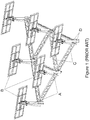
- the support structure in that instance provides a supporting frame supporting a stable pylon (A) for each heliostat (B) and the pylons are arranged in a triangular pattern with the pylons being secured together by girders (C), preferably in the form of trusses, secured to projecting plates (D) welded to the pylons and forming a framework therewith.
- girders preferably in the form of trusses
- D projecting plates
- this arrangement will work effectively when installed on relatively even ground but may be somewhat problematical on at least some types of undulating ground. It also involves a significant amount of welding that contributes to the cost of the support structure and welds require additional corrosion protection. The latter applies particularly to the type of trusses employed.
- US Patent No. 2,284,898 discloses a structural system having standardized parts removably bolted together and providing variable webs and variable chords to take the place of wood and steel joists.
- the chords comprising a plurality of transversely nested continuously curved sheets of metal in substantially continuous contact with one another and having a plurality of registering holes distributed along the section for bolting the sheets together and securing other structural members thereto at selected positions.
- US Patent Application Publication No. US 2013/0312361 discloses a truss having an upper and lower chord member each extending in generally the same longitudinal direction and in spaced apart relation.
- the truss includes a plurality of web members each with a first and second end, the web members including a crimped portion at the first and second end with openings, wherein the first and second ends and openings of adjacent web members overlap.
- US Patent Application Publication No. US 2002/0069606 discloses a joist having an upper chord and a lower chord and a plurality of compression and tension webs extending between the chorda and secured thereto by means of bolts. A single bolt per connection or nodal point is used to secure the compression and tension webs to the chords.
- a supporting frame including a truss composed of an upper straight frame member and a generally parallel lower straight frame member with each of the frame members being operatively supported at or towards its ends in spaced relationship relative to each other and wherein two spans of a divergent inclined brace member extend between the upper and lower straight frame members with the ends of the brace member spans each being secured to the lower straight frame member by means of a fastener associated with it, wherein the brace member spans are of deformable material that may be tubular or of a suitable section selected from an angle section and a channel section, and the ends are flattened and secured to the lower straight frame member, wherein a flattened central region of the brace member has an elongate longitudinal slot to accommodate a fastener or fasteners passing through the flattened central region allowing for limited relative longitudinal movement of the upper and lower straight frame members to take place prior to the fastener or fasteners associated with the central region of the brace member being secured to the upper straight frame member,
- the upper and lower straight frame members to also be tubular or of a suitable section such as angle section or channel section and to have their ends flattened for attachment to corresponding ends of cooperating upper and lower straight frame members of co-operating trusses or for attachment to different items or anchorage points.
- the fastener assemblies may be releasable such as in the instance of screw threaded fasteners or they may be of the rivet type that are considerably more permanent but in at least many instances appreciably less expensive.
- Releasable fasteners clearly provide the advantage that should be supporting surface of a frame move somewhat to cause stresses to be developed in the truss, the releasable fasteners can be loosened and retightened to accommodate longitudinal movement of the upper and lower straight frame members relative to each other.
- the trusses be used to support multiple upright pylons from a generally horizontal supporting frame assembly in which each pylon is height adjustable relative to the plane of the frame assembly and has associated with it a releasable clamping assembly for clamping each pylon such that the pylon and supporting frame assembly can be supported on a supporting surface with multiple pylons having their lowermost ends engaging the supporting surface.
- the brace member spans are limited in number to one elongate tubular brace member unit having two divergent brace member spans for each span of frame members between two adjacent pylons or other items being operatively supported by the supporting frame assembly.
- a supporting frame assembly as defined above in combination with height adjustable pylons and in which the supporting frame assembly includes at least two trusses meeting at a corner with the frame members of each truss being generally co-planar and the pylons being urged in the plane of the supporting frame into a corner between the frame members of each pair of trusses so as to extend at generally right angles to a plane including the two frame members, and at least one fastener assembly having two end portions each of which is anchored relative to its associated frame member so as to extend transversely relative to the associated frame member and wherein the fastener assembly includes an intermediate saddle portion engaging a surface of the pylon that is directed outwardly relative to the corner so that the pylon is urged by the fastener assembly into the corner when the fastener assembly is tightened to thereby engage the pylon and lock it axially relative to the frame members in a selected position.
- each of the end portions of the fastener assembly to pass through the associated frame member with a head or nut engaging an outside of the associated frame member to anchor it relative to the frame member; for the fastener assembly to be a single elongate fastener having an arcuate central saddle portion formed to closely follow the outer surface of the pylon and two straight end portions that constitute said end portions; for the angle at which the frame members meet each other to be a right angle or an acute angle, preferably about 60°, for the surface of the frame members engaged by the pylon to be pre-formed to provide a contact surface conforming substantially to the outer surface of the pylon; and for the frame members to be tubular frame members or sections made of a deformable metal that can be pressed to provide said contact surfaces and flattened and perforated towards their ends that are bolted together.
- the invention is applied to a supporting frame assembly (1) that supports multiple height adjustable pylons (2) that, in this particular instance, may be used to support heliostats, as indicated above.
- the supporting frame assembly in this instance has multiple frame member arranged in pairs to form trusses each composed of an upper straight frame member (3) and a parallel lower straight frame member (4) with the two frame members being held in parallel relationship by inclined brace members (5) extending between the upper and lower straight frame members.
- the free ends (6) of the frame members are flattened and perforated to receive connecting bolts (7) passing through overlapped flattened ends.
- the brace members are of tubular metal and have flattened ends (8) that are also perforated to accommodate bolts (9) passing through them and a flattened central region (11) has an elongate slot (12) that allows for longitudinal adjustment of the relative positions of the two straight frame members to accommodate any undulations in a support surface on which the pylons and supporting frame assembly are located.
- the brace elements intercept the upper straight frame member in order to strengthen it for people to stand on it whilst the lower frame member is less important from this perspective due to its generally close proximity to the ground which is typically not movable. The braces thus diverge from the central flattened central region.
- the main supporting frame is of equilateral triangular shape in plan view with a side of the triangle being dimensioned to correspond with a standard commercially available length of metal tube, such as 6 metres, for example.
- a pylon (2) is supported by the frame at each corner of the main supporting frame at a corner that makes an angle of 60° between the frame members of the trusses.
- each of the frame members of the sub-frame assembly is made to one half of a standard commercially available length of metal tube, in this instance 3 metres.
- the tubular brace members (5) are each composed of one half of the length of a standard commercially available tube and span between a position close to each pylon (2) and each intermediate pylon (15), as shown especially in Figure 3 . There is thus a single elongate tubular brace having its flattened central region secured to a central region of each span of the upper straight frame members (3, 16), and its two flattened end regions that are perforated and secured towards the end regions of the corresponding span of the lower frame members (4, 17).
- each tubular brace is secured to the central region of the upper straight frame member (3,16) by means of a single screw threaded fastener (18) passing through the elongate slot (12) extending in the longitudinal direction so that it can accommodate alterations in the relative longitudinal positions of the upper and lower straight frame members that may be occasioned by undulations in a supporting surface that cannot be practically accommodated by axial adjustment of the pylons.
- the frame members are, in each case, generally co-planar and the associated pylon is urged into the associated corner so as to extend at generally right angles to a generally horizontal plane including the two frame members.
- a fastener assembly in the form of a single elongate fastener (21) having an arcuate intermediate saddle portion (22) engaging a surface of the pylon that is directed outwardly relative to the corner so that the pylon is urged by the fastener assembly into the corner region.
- the saddle portion is formed to closely follow the outer surface of the pylon and the fastener has two straight screw threaded end portions (23) each of which passes through the associated frame member with a nut (24) engaging an outside of the associated frame member.
- the straight end portions extend transversely, typically at almost right angles, relative to the associated frame member.
- the nuts (24) associated with each screw threaded end are such that when tightened, the nuts cause the saddle portion to engage the pylon and lock it in its axial direction relative to the frame members in a selected position.
- the surfaces of the frame members engaged by the pylon are pre-formed to provide a curved contact surface (25) conforming substantially to the outer surface of the pylon that is engaged by the frame member.
- the frame members and brace members are tubular and made of a deformable metal that can be pressed to flatten the ends or a central zone of the brace members and to provide said contact surfaces and flattened perforated ends of the frame members that are bolted together. It is therefore convenient to use galvanised iron or steel in the fabrication of the various components as the only fabrication procedure to be carried out is to cut the lengths at one position and a cut end can be relatively easily provided with adequate corrosion protection, unlike welded zones.
- the adjustment of the axial positions of the individual pylons and intermediate pylons is enabled by the associated fastener assembly that bridges a corner between two joined straight frame or sub-frame members with the pylon firmly clamped between the end regions of the frame members and the fastener.
- the arrangement described above therefore provides a pylon and generally horizontal supporting frame assembly in which the multiple frame members support multiple pylons extending at generally right angles to a plane of the frame assembly.
- Each pylon is height adjustable relative to the plane of the supporting frame assembly and has associated with it a releasable clamping assembly for clamping each pylon such that the pylon and supporting frame assembly is supported on a supporting surface with multiple pylons engaging the supporting surface, Preferably all of the pylons and intermediate pylons having their lowermost ends engaging the supporting surface.
- the physical characteristics of the supporting surface are not particularly suitable in regions where some pylons are to engage the supporting surface and additional accessories such as a base plate (27) or radially extending leg (28) optionally having a sleeve (29) for receiving a laterally offset foot or a ground engaging screw (not shown).
- additional accessories such as a base plate (27) or radially extending leg (28) optionally having a sleeve (29) for receiving a laterally offset foot or a ground engaging screw (not shown).
- the latter are illustrated in Figure 10 .
- each pylon In order to set up a pylon and supporting frame assembly as described above, the various pylons and frame members are assembled with associated brace members having central flattened regions loosely connected to the upper frame members. Once this has been achieved, the bolts connecting the overlapped flattened ends of the frame members can be tightened.
- the height of each pylon may be adjusted prior to clamping the pylon in a selected vertical position relative to the supporting frame assembly which is carried out by clamping the two vertically spaced fastener assemblies associated with the upper and lower straight frame members in position. This can be followed by tightening of the bolts that connect the flattened ends of the brace members to the lower frame members and finally by tightening the bolts that secure the flattened central region of the brace members to the upper frame members. Following the above procedure or any other suitable procedure will enable the entire assembly to be supported on a reasonably undulating surface without any difficulties. Each pylon will be firmly clamped in its operative position.
- the bolts connecting the central regions of the brace members to the upper frame members can be loosened and re-tightened with the stresses having been relieved.
- Other fasteners may be similarly loosened and then re-tightened
- upper and lower frame members operate as two sides of a parallelogram in contradistinction to the instance in which trusses comprise upper and lower frame members that are firmly and immovably attached to each other by multiple diagonal brace members that are typically welded to the frame members thereby necessitating considerable manual labour and material input and also considerable additional corrosion protection.
- the truss structure of this invention is much simpler than prior art arrangements as there is no welding and accompanying additional corrosion protection required.
- the basic geometry of the frame assembly in plan view can be changed widely and need not be based on a triangle as in the embodiment described above.
- the shape of the frame could be square, rectangular, or of any other polygonal shape such as hexagonal.
Landscapes
- Engineering & Computer Science (AREA)
- General Engineering & Computer Science (AREA)
- Architecture (AREA)
- Mechanical Engineering (AREA)
- Thermal Sciences (AREA)
- Physics & Mathematics (AREA)
- Chemical & Material Sciences (AREA)
- Combustion & Propulsion (AREA)
- Sustainable Energy (AREA)
- Sustainable Development (AREA)
- Life Sciences & Earth Sciences (AREA)
- Civil Engineering (AREA)
- Structural Engineering (AREA)
- Joining Of Building Structures In Genera (AREA)
- Tents Or Canopies (AREA)
- Rod-Shaped Construction Members (AREA)
- Bridges Or Land Bridges (AREA)
- Clamps And Clips (AREA)
- Moulding By Coating Moulds (AREA)
- Mutual Connection Of Rods And Tubes (AREA)
Description
- This application claims priority from South African provisional patent application number
2015/02248 filed on 7th April 2015 - This invention relates to a supporting frame assembly that may, for example, be used to support items such as pylons used in turn to support items such as heliostats, photovoltaic panels, water heating panels whether they be of the flat panel type or composed of multiple vacuum tubes, wind turbines (aerofoil powered generators) or other wind activated machines, or any other items that require stable support in a particular place, generally an outdoors space.
- More particularly, the invention relates to supporting frame assemblies of a generally polygonal shape in plan view.
- Support frame assemblies of the type with which this invention is concerned are often used in regions in which a generally horizontal support surface may undulate, at least to some extent, that renders conventional supporting frame assemblies that employ rigid trusses arranged in a polygonal configuration inappropriate or, at least to some extent ineffective, in view of the different heights at which different parts of a supporting frame assembly become supported.
- A conventional rigid truss may be composed of a pair of parallel spaced frame members interconnected by multiple diagonal braces or struts that together form a rigid and unyielding truss. Typically the ends of a truss are rigidly connected to an item being supported by the frame. In instances in which the item being supported is required to be in a generally particular orientation, such as generally upright in the case of a pylon, such an arrangement does not work effectively.
- For example, in the instance of a supporting frame to which a pylon supported heliostat is attached, the focusing of reflected solar energy accurately towards a central tower receiver is imperative and consequently the stability of the supporting frame and pylon must ensure the necessary accuracy that in turn depends on the stability of the supporting frame and pylon. Also, it should be noted that support structures for the heliostats in such an application are responsible for an appreciable proportion of the capital expenditure on an entire installation.
- In consequence of this, the development of more stable and less costly support structures has been an ongoing challenge and one support structure that has been evolved forms the subject matter of our published international patent application
WO2014072905 . As shown in accompanyingFigure 1 , the support structure in that instance provides a supporting frame supporting a stable pylon (A) for each heliostat (B) and the pylons are arranged in a triangular pattern with the pylons being secured together by girders (C), preferably in the form of trusses, secured to projecting plates (D) welded to the pylons and forming a framework therewith. It is considered that this arrangement will work effectively when installed on relatively even ground but may be somewhat problematical on at least some types of undulating ground. It also involves a significant amount of welding that contributes to the cost of the support structure and welds require additional corrosion protection. The latter applies particularly to the type of trusses employed. - It is considered that there is yet appreciable scope for improvement in an arrangement of pylons and a supporting frame for purposes such as this or for supporting any other items such as those identified above.
-
US Patent No. 2,284,898 discloses a structural system having standardized parts removably bolted together and providing variable webs and variable chords to take the place of wood and steel joists. The chords comprising a plurality of transversely nested continuously curved sheets of metal in substantially continuous contact with one another and having a plurality of registering holes distributed along the section for bolting the sheets together and securing other structural members thereto at selected positions. - US Patent Application Publication No.
US 2013/0312361 discloses a truss having an upper and lower chord member each extending in generally the same longitudinal direction and in spaced apart relation. The truss includes a plurality of web members each with a first and second end, the web members including a crimped portion at the first and second end with openings, wherein the first and second ends and openings of adjacent web members overlap. - US Patent Application Publication No.
US 2002/0069606 discloses a joist having an upper chord and a lower chord and a plurality of compression and tension webs extending between the chorda and secured thereto by means of bolts. A single bolt per connection or nodal point is used to secure the compression and tension webs to the chords. - The preceding discussion of the background to the invention is intended only to facilitate an understanding of the present invention. It should be appreciated that the discussion is not an acknowledgment or admission that any of the material referred to was part of the common general knowledge in the art as at the priority date of the application.
- In accordance with this invention there is provided a supporting frame including a truss composed of an upper straight frame member and a generally parallel lower straight frame member with each of the frame members being operatively supported at or towards its ends in spaced relationship relative to each other and wherein two spans of a divergent inclined brace member extend between the upper and lower straight frame members with the ends of the brace member spans each being secured to the lower straight frame member by means of a fastener associated with it, wherein the brace member spans are of deformable material that may be tubular or of a suitable section selected from an angle section and a channel section, and the ends are flattened and secured to the lower straight frame member, wherein a flattened central region of the brace member has an elongate longitudinal slot to accommodate a fastener or fasteners passing through the flattened central region allowing for limited relative longitudinal movement of the upper and lower straight frame members to take place prior to the fastener or fasteners associated with the central region of the brace member being secured to the upper straight frame member, wherein the relative longitudinal movement enables the upper and lower frame members to operate as two sides of a parallelogram to relieve or avoid stresses that may be occasioned by undulations in a supporting surface.
- Further features of the invention provide for the upper and lower straight frame members to also be tubular or of a suitable section such as angle section or channel section and to have their ends flattened for attachment to corresponding ends of cooperating upper and lower straight frame members of co-operating trusses or for attachment to different items or anchorage points.
- It will be appreciated that the fastener assemblies may be releasable such as in the instance of screw threaded fasteners or they may be of the rivet type that are considerably more permanent but in at least many instances appreciably less expensive. Releasable fasteners clearly provide the advantage that should be supporting surface of a frame move somewhat to cause stresses to be developed in the truss, the releasable fasteners can be loosened and retightened to accommodate longitudinal movement of the upper and lower straight frame members relative to each other.
- It is a particular feature of the invention that the trusses be used to support multiple upright pylons from a generally horizontal supporting frame assembly in which each pylon is height adjustable relative to the plane of the frame assembly and has associated with it a releasable clamping assembly for clamping each pylon such that the pylon and supporting frame assembly can be supported on a supporting surface with multiple pylons having their lowermost ends engaging the supporting surface.
- Preferably, the brace member spans are limited in number to one elongate tubular brace member unit having two divergent brace member spans for each span of frame members between two adjacent pylons or other items being operatively supported by the supporting frame assembly.
- In accordance with another aspect not according to the invention there is provided a supporting frame assembly as defined above in combination with height adjustable pylons and in which the supporting frame assembly includes at least two trusses meeting at a corner with the frame members of each truss being generally co-planar and the pylons being urged in the plane of the supporting frame into a corner between the frame members of each pair of trusses so as to extend at generally right angles to a plane including the two frame members, and at least one fastener assembly having two end portions each of which is anchored relative to its associated frame member so as to extend transversely relative to the associated frame member and wherein the fastener assembly includes an intermediate saddle portion engaging a surface of the pylon that is directed outwardly relative to the corner so that the pylon is urged by the fastener assembly into the corner when the fastener assembly is tightened to thereby engage the pylon and lock it axially relative to the frame members in a selected position.
- Further features of this other aspect provide for each of the end portions of the fastener assembly to pass through the associated frame member with a head or nut engaging an outside of the associated frame member to anchor it relative to the frame member; for the fastener assembly to be a single elongate fastener having an arcuate central saddle portion formed to closely follow the outer surface of the pylon and two straight end portions that constitute said end portions; for the angle at which the frame members meet each other to be a right angle or an acute angle, preferably about 60°, for the surface of the frame members engaged by the pylon to be pre-formed to provide a contact surface conforming substantially to the outer surface of the pylon; and for the frame members to be tubular frame members or sections made of a deformable metal that can be pressed to provide said contact surfaces and flattened and perforated towards their ends that are bolted together.
- In order that the invention may be more fully understood one embodiment incorporating both aspects of the invention will now be described with reference to the accompanying drawings.
- In the drawings:
- Figure 1
- is illustrates in three-dimensional view one example of prior art type of pylon and supporting frame assembly of the general nature with which this invention is concerned;
- Figure 2
- is a similar three-dimensional view of an equivalent pylon and supporting frame assembly to which the present invention has been applied;
- Figure 3
- is an elevation showing one half of one side or span of the assembly illustrated in
Figure 2 ; - Figure 4
- is a schematic plan view showing one pylon and its relationship with an associated corner of the supporting frame assembly;
- Figure 5
- is the same as
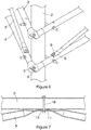
Figure 4 with the pylon removed so as to clearly illustrate the tubular frame members and associated fastener assembly; - Figure 6
- is a three-dimensional view of one corner of the supporting frame assembly showing two trusses connected together at a corner of the assembly and one pylon secured thereto;
- Figure 7
- is a sectional elevation detail showing the attachment of a tubular brace member secured to an upper straight frame member;
- Figure 8
- illustrates, in plan view, the attachment of an intermediate pylon to a straight frame member;
- Figure 9
- is a three-dimensional view showing the attachment of trusses to each other where they intersect at a position where an intermediate pylon is supported by the frame assembly; and,
- Figure 10
- illustrates schematically in isometric view optional auxiliary components that may be used to stabilise a pylon should this be necessary.
- In the embodiment of the invention illustrated in
Figures 2 to 9 of the drawings, the invention is applied to a supporting frame assembly (1) that supports multiple height adjustable pylons (2) that, in this particular instance, may be used to support heliostats, as indicated above. The supporting frame assembly in this instance has multiple frame member arranged in pairs to form trusses each composed of an upper straight frame member (3) and a parallel lower straight frame member (4) with the two frame members being held in parallel relationship by inclined brace members (5) extending between the upper and lower straight frame members. The free ends (6) of the frame members are flattened and perforated to receive connecting bolts (7) passing through overlapped flattened ends. - The brace members are of tubular metal and have flattened ends (8) that are also perforated to accommodate bolts (9) passing through them and a flattened central region (11) has an elongate slot (12) that allows for longitudinal adjustment of the relative positions of the two straight frame members to accommodate any undulations in a support surface on which the pylons and supporting frame assembly are located. The brace elements intercept the upper straight frame member in order to strengthen it for people to stand on it whilst the lower frame member is less important from this perspective due to its generally close proximity to the ground which is typically not movable. The braces thus diverge from the central flattened central region.
- In the particular instance of the frame assembly illustrated in
Figure 2 , the main supporting frame is of equilateral triangular shape in plan view with a side of the triangle being dimensioned to correspond with a standard commercially available length of metal tube, such as 6 metres, for example. A pylon (2) is supported by the frame at each corner of the main supporting frame at a corner that makes an angle of 60° between the frame members of the trusses. - In addition, three intermediate pylons (15) are supported midway between the corners of the main frame assembly in the corners of a triangular sub-frame that has its upper straight frame members (16) and lower straight frame members (17) of the trusses attached to the midpoints of the main frame members (3, 4). In this manner corners are generated in the supporting sub-frame assembly to accommodate three intermediate pylons (15). For economy of tubular material, each of the frame members of the sub-frame assembly is made to one half of a standard commercially available length of metal tube, in this
instance 3 metres. - The tubular brace members (5) are each composed of one half of the length of a standard commercially available tube and span between a position close to each pylon (2) and each intermediate pylon (15), as shown especially in
Figure 3 . There is thus a single elongate tubular brace having its flattened central region secured to a central region of each span of the upper straight frame members (3, 16), and its two flattened end regions that are perforated and secured towards the end regions of the corresponding span of the lower frame members (4, 17). - The flattened central region (11) of each tubular brace is secured to the central region of the upper straight frame member (3,16) by means of a single screw threaded fastener (18) passing through the elongate slot (12) extending in the longitudinal direction so that it can accommodate alterations in the relative longitudinal positions of the upper and lower straight frame members that may be occasioned by undulations in a supporting surface that cannot be practically accommodated by axial adjustment of the pylons.
- The frame members are, in each case, generally co-planar and the associated pylon is urged into the associated corner so as to extend at generally right angles to a generally horizontal plane including the two frame members. A fastener assembly in the form of a single elongate fastener (21) having an arcuate intermediate saddle portion (22) engaging a surface of the pylon that is directed outwardly relative to the corner so that the pylon is urged by the fastener assembly into the corner region. The saddle portion is formed to closely follow the outer surface of the pylon and the fastener has two straight screw threaded end portions (23) each of which passes through the associated frame member with a nut (24) engaging an outside of the associated frame member. The straight end portions extend transversely, typically at almost right angles, relative to the associated frame member. The nuts (24) associated with each screw threaded end are such that when tightened, the nuts cause the saddle portion to engage the pylon and lock it in its axial direction relative to the frame members in a selected position.
- In order to enhance the gripping effect of the frame members on the pylon, the surfaces of the frame members engaged by the pylon are pre-formed to provide a curved contact surface (25) conforming substantially to the outer surface of the pylon that is engaged by the frame member.
- In each instance the frame members and brace members are tubular and made of a deformable metal that can be pressed to flatten the ends or a central zone of the brace members and to provide said contact surfaces and flattened perforated ends of the frame members that are bolted together. It is therefore convenient to use galvanised iron or steel in the fabrication of the various components as the only fabrication procedure to be carried out is to cut the lengths at one position and a cut end can be relatively easily provided with adequate corrosion protection, unlike welded zones.
- The adjustment of the axial positions of the individual pylons and intermediate pylons is enabled by the associated fastener assembly that bridges a corner between two joined straight frame or sub-frame members with the pylon firmly clamped between the end regions of the frame members and the fastener.
- The arrangement described above therefore provides a pylon and generally horizontal supporting frame assembly in which the multiple frame members support multiple pylons extending at generally right angles to a plane of the frame assembly. Each pylon is height adjustable relative to the plane of the supporting frame assembly and has associated with it a releasable clamping assembly for clamping each pylon such that the pylon and supporting frame assembly is supported on a supporting surface with multiple pylons engaging the supporting surface, Preferably all of the pylons and intermediate pylons having their lowermost ends engaging the supporting surface.
- Of course, it may happen that the physical characteristics of the supporting surface are not particularly suitable in regions where some pylons are to engage the supporting surface and additional accessories such as a base plate (27) or radially extending leg (28) optionally having a sleeve (29) for receiving a laterally offset foot or a ground engaging screw (not shown). The latter are illustrated in
Figure 10 . - In order to set up a pylon and supporting frame assembly as described above, the various pylons and frame members are assembled with associated brace members having central flattened regions loosely connected to the upper frame members. Once this has been achieved, the bolts connecting the overlapped flattened ends of the frame members can be tightened. The height of each pylon may be adjusted prior to clamping the pylon in a selected vertical position relative to the supporting frame assembly which is carried out by clamping the two vertically spaced fastener assemblies associated with the upper and lower straight frame members in position. This can be followed by tightening of the bolts that connect the flattened ends of the brace members to the lower frame members and finally by tightening the bolts that secure the flattened central region of the brace members to the upper frame members. Following the above procedure or any other suitable procedure will enable the entire assembly to be supported on a reasonably undulating surface without any difficulties. Each pylon will be firmly clamped in its operative position.
- In the event that, over a period of time, stresses develop in the supporting frame assembly, the bolts connecting the central regions of the brace members to the upper frame members can be loosened and re-tightened with the stresses having been relieved. Other fasteners may be similarly loosened and then re-tightened
- It will be understood that the upper and lower frame members operate as two sides of a parallelogram in contradistinction to the instance in which trusses comprise upper and lower frame members that are firmly and immovably attached to each other by multiple diagonal brace members that are typically welded to the frame members thereby necessitating considerable manual labour and material input and also considerable additional corrosion protection.
- The truss structure of this invention is much simpler than prior art arrangements as there is no welding and accompanying additional corrosion protection required.
- Of course, the basic geometry of the frame assembly in plan view can be changed widely and need not be based on a triangle as in the embodiment described above. Thus, for example, the shape of the frame could be square, rectangular, or of any other polygonal shape such as hexagonal.
- Numerous other variations may be made to the embodiment of the invention described above without departing from the scope hereof.
- Throughout the specification and claims unless the contents requires otherwise the word 'comprise' or variations such as 'comprises' or 'comprising' will be understood to imply the inclusion of a stated integer or group of integers but not the exclusion of any other integer or group of integers.
Claims (7)
- A supporting frame (1) including a truss composed of an upper straight frame member (3) and a generally parallel lower straight frame member (4) with each of the frame members being operatively supported at or towards its ends in spaced relationship relative to each other and wherein two spans of a divergent inclined brace member (5) extend between the upper and lower straight frame members with the ends (8) of the brace member spans each being secured to the lower straight frame member (4) by means of a fastener (9) associated with it, wherein the brace member spans are of deformable material that may be tubular or of a suitable section selected from an angle section and a channel section, and the ends (8) are flattened and secured to the lower straight frame member (4), the supporting frame being characterized in that a flattened central region (11) of the brace member (5) has an elongate longitudinal slot (12) to accommodate a fastener or fasteners passing through the flattened central region (11) allowing for limited relative longitudinal movement of the upper and lower straight frame members (3, 4) to take place prior to the fastener or fasteners associated with the central region of the brace member (5) being secured to the upper (3) straight frame member, wherein the relative longitudinal movement enables the upper and lower frame members (3, 4) to operate as two sides of a parallelogram to relieve or avoid stresses that may be occasioned by undulations in a supporting surface.
- A supporting frame as claimed in claim 1, in which the upper and lower straight frame members are tubular or of a suitable section selected from an angle section and a channel section with their ends flattened for attachment to corresponding ends of cooperating upper or lower straight frame member of a co-operating truss.
- A supporting frame as claimed in claim 1 or claim 2 in which the brace member spans are limited in number to one elongate tubular brace member unit having two divergent brace member spans for each span of frame members between two adjacent pylons or other items being operatively supported by the supporting frame assembly.
- A supporting frame as claimed in any one of the preceding claims in which multiple trusses support multiple upright pylons from a generally horizontal supporting frame assembly.
- A supporting frame as claimed in claim 4 in which the supporting frame assembly includes at least two trusses meeting at a corner with upper and lower frame members of the two trusses being generally co-planar and the pylons are urged in the plane of the supporting frame into a corner between the frame members of each pair of trusses so as to extend at generally right angles to a plane including the two frame members.
- A supporting frame as claimed in either one of claims 4 or 5 in which three trusses support three upright pylons.
- A supporting frame as claimed in claim 6 in which the three trusses support three shorter trusses of a triangular sub-frame arranged to connect midpoints of the three longer trusses and wherein an upright pylon is operatively supported at each of three corners of a resulting sub-frame and the three shorter trusses are each composed of upper (16) and lower (17) straight frame members wherein at least two spans of a divergent inclined brace member extend between the upper and lower straight frame members with the ends of the brace member spans each being securable to the upper or lower straight frame member by means of a fastener associated with it, the supporting frame providing limited relative longitudinal movement of the upper and lower straight frame members to take place prior to a fastener associated with at least one end of each brace member span being secured to fix the positions at which the ends of the brace member spans are attached to the upper and lower straight frame member.
Applications Claiming Priority (1)
| Application Number | Priority Date | Filing Date | Title |
|---|---|---|---|
| ZA201502248 | 2015-04-07 |
Publications (2)
| Publication Number | Publication Date |
|---|---|
| EP3078922A1 EP3078922A1 (en) | 2016-10-12 |
| EP3078922B1 true EP3078922B1 (en) | 2019-06-05 |
Family
ID=55699448
Family Applications (1)
| Application Number | Title | Priority Date | Filing Date |
|---|---|---|---|
| EP16163589.1A Active EP3078922B1 (en) | 2015-04-07 | 2016-04-01 | Supporting frame assembly |
Country Status (12)
| Country | Link |
|---|---|
| US (1) | US9932749B2 (en) |
| EP (1) | EP3078922B1 (en) |
| CN (1) | CN106051381B (en) |
| AP (1) | AP2016009130A0 (en) |
| AU (1) | AU2016202006B2 (en) |
| CL (1) | CL2016000794A1 (en) |
| ES (1) | ES2744613T3 (en) |
| IL (1) | IL244978B (en) |
| MA (1) | MA39626A (en) |
| MX (1) | MX371355B (en) |
| TN (1) | TN2016000118A1 (en) |
| ZA (1) | ZA201602338B (en) |
Families Citing this family (12)
| Publication number | Priority date | Publication date | Assignee | Title |
|---|---|---|---|---|
| AU2016202007B2 (en) * | 2015-04-07 | 2020-07-09 | Stellenbosch University | Frame supported height adjustable pylon |
| US10036180B1 (en) * | 2015-04-17 | 2018-07-31 | Mark Edward Jansen | Fence post anchor installation system |
| JP2020503074A (en) * | 2016-12-27 | 2020-01-30 | トレガー・ペレット・グリルズ,エルエルシー | Leg assembly method and system |
| CN111877833A (en) * | 2020-07-10 | 2020-11-03 | 浙江德宝通讯科技股份有限公司 | Pipe tower reinforcing device and reinforcing method |
| CN111947034A (en) * | 2020-07-24 | 2020-11-17 | 中国市政工程华北设计研究总院有限公司 | A three-pipe natural gas release tower |
| CN113364406B (en) * | 2021-05-24 | 2022-08-30 | 浙江大学 | Tracking type large-span photovoltaic support structure unit capable of being assembled and support |
| CN114244261B (en) * | 2022-01-03 | 2024-01-09 | 孟小龙 | Pneumatic heliostat device |
| KR102697224B1 (en) * | 2022-01-06 | 2024-08-22 | 한국전력공사 | Device for installing new angle member using for enclosing method of transmission tower |
| US12132378B2 (en) * | 2022-07-06 | 2024-10-29 | General Electric Renovables Espana, S.L. | Coil support structure for superconducting coils in a superconducting machine |
| US12421749B2 (en) * | 2022-08-10 | 2025-09-23 | Great Plains Tower Products Llc | Exhaust stack lattice tower |
| CN115384712A (en) * | 2022-09-06 | 2022-11-25 | 中交第三航务工程局有限公司 | Semi-submersible floating type wind power generation device |
| US12525914B2 (en) * | 2023-05-22 | 2026-01-13 | Nextracker Llc | Solar module couplings for solar tracker |
Family Cites Families (63)
| Publication number | Priority date | Publication date | Assignee | Title |
|---|---|---|---|---|
| US835281A (en) * | 1906-05-31 | 1906-11-06 | Broderick Haskell | Telegraph-pole. |
| US1787167A (en) * | 1927-12-07 | 1930-12-30 | Frederick L Purdy | Connecting means for rafters |
| US1813373A (en) * | 1929-01-22 | 1931-07-07 | Charles L Wooldridge Inc | Lattice beam |
| US1865059A (en) * | 1929-07-18 | 1932-06-28 | Budd Edward G Mfg Co | Girder construction |
| US2030262A (en) * | 1930-01-27 | 1936-02-11 | Maddock Thomas | Truss or bridge |
| US2284898A (en) * | 1939-11-29 | 1942-06-02 | Rudolph B Hartman | Structural system |
| US2906551A (en) * | 1958-08-04 | 1959-09-29 | Tubular Structures Corp Of Ame | Clamping devices |
| US3043409A (en) * | 1959-05-25 | 1962-07-10 | Rapids Standard Co Inc | Perforated structural angle |
| US3247629A (en) * | 1962-06-05 | 1966-04-26 | Behlen Mfg Company Inc | Catenary roof structure |
| US3330087A (en) * | 1963-09-14 | 1967-07-11 | Arthur L Troutner | Long span, high load, composite truss joist |
| US3314209A (en) * | 1965-04-12 | 1967-04-18 | Arthur L Troutner | Composite truss joist having chords and links of adjustable angle |
| US3318561A (en) * | 1965-05-12 | 1967-05-09 | Antenna Specialists Co | Antenna support bracket |
| US3386222A (en) * | 1966-05-23 | 1968-06-04 | Arthur L. Troutner | High-load truss joist link |
| US3422591A (en) * | 1967-03-20 | 1969-01-21 | Arthur L Troutner | Composite truss joist with offset bearing |
| US3409259A (en) * | 1967-06-19 | 1968-11-05 | Turco Mfg Company | Gym set headbar attachment channel |
| US3564783A (en) * | 1969-08-05 | 1971-02-23 | Fosco Fabricators Inc | Superhighway driver direction structure erectible in the field |
| US3570204A (en) * | 1969-09-24 | 1971-03-16 | Timber Structures Inc | Truss joists |
| US3925942A (en) * | 1973-11-12 | 1975-12-16 | Space Age Ind Inc | Modular structure formed of interconnected tubular members |
| US3885365A (en) * | 1974-06-06 | 1975-05-27 | Joe Warren Cox | Self-adjusting stair |
| US3946532A (en) * | 1974-09-20 | 1976-03-30 | Simpson Manufacturing Company, Inc. | Truss structure with fastener plate joint assembly |
| US4007573A (en) * | 1976-02-09 | 1977-02-15 | Simpson Manufacturing Co., Inc. | Truss top bearing clip |
| US4094116A (en) * | 1977-06-06 | 1978-06-13 | Simpson Manufacturing Co., Inc. | Web tube with separated end walls |
| US4214841A (en) * | 1977-06-20 | 1980-07-29 | Hayashi Henry T | Clamp-connector for joining three tubular members at corners |
| JPH07104471B2 (en) * | 1983-08-03 | 1995-11-13 | 敬 森 | Sun collecting device mounting base |
| US4624599A (en) * | 1984-06-14 | 1986-11-25 | Piasecki Aircraft Corp. | Multi-tubular truss joint and method of joining tube ends |
| GB2214944B (en) * | 1988-02-05 | 1991-09-04 | William Maldwyn Rowlands | Adjustable roof truss |
| US4957186A (en) * | 1989-12-11 | 1990-09-18 | T J International, Inc. | Span-adjustable open-web support bracket |
| US5145030A (en) * | 1991-09-11 | 1992-09-08 | Waco International Corporation | Guard rail post |
| US5787673A (en) * | 1992-09-14 | 1998-08-04 | Pirod, Inc. | Antenna support with multi-direction adjustability |
| JP3390595B2 (en) * | 1996-01-17 | 2003-03-24 | 株式会社巴コーポレーション | Joint structure of truss members |
| US5920291A (en) * | 1996-01-22 | 1999-07-06 | Baltimore Gas & Electric Company | Antenna mounting bracket and assembly |
| US6225962B1 (en) * | 1998-09-18 | 2001-05-01 | Gabriel Electronics Incorporated | Apparatus and method for an adjustable linkage |
| US6043795A (en) * | 1998-10-02 | 2000-03-28 | Radio Frequency Systems, Inc. | Support system for large antennas, including multi-beam antennas |
| CA2271403A1 (en) * | 1999-04-22 | 2000-10-22 | Georges Gosselin | Bolted metal joist |
| US6752438B2 (en) * | 2000-11-15 | 2004-06-22 | U.S. Fence, Llc | Adjustable gate hinge and latch, and system |
| US6561473B1 (en) * | 2001-03-30 | 2003-05-13 | Pirod, Inc. | Universal pipe mounting clamp and assembly |
| CA2385380A1 (en) * | 2001-05-31 | 2002-11-30 | Tatsuo Ono | Mounting method for a handrail in a frame scafolding |
| US6499266B1 (en) * | 2001-07-16 | 2002-12-31 | Lemar Industries Corp. | Truss construction |
| WO2003008722A1 (en) * | 2001-07-19 | 2003-01-30 | Weeks Peacock Quality Homes Pty. Ltd. | Truss |
| US6532953B1 (en) * | 2001-08-30 | 2003-03-18 | The Boeing Company | Geometric dome stowable tower reflector |
| US7779599B2 (en) * | 2004-03-31 | 2010-08-24 | Safway Services, Llc | Articulating work platform support system, work platform system, and methods of use thereof |
| US7113145B1 (en) * | 2005-05-23 | 2006-09-26 | Valmont Industries, Inc. | Antenna mounting bracket assembly |
| US7086207B2 (en) * | 2005-06-09 | 2006-08-08 | Andrew Corporation | Antenna sector frame |
| ES2280138B1 (en) * | 2006-02-21 | 2008-08-16 | Er Automatizacion, S.A. | A DYNAMIC SOLAR TRACKING SYSTEM. |
| US20080053032A1 (en) * | 2006-08-31 | 2008-03-06 | Hockemeyer Timothy J | Support column system for emergency isolation and treatment shelter (EITS) |
| US20080184653A1 (en) * | 2006-10-13 | 2008-08-07 | Bauman Kevin P | Truss Tower Leg Reinforcing System |
| US7677009B2 (en) * | 2007-02-02 | 2010-03-16 | Nova Chemicals Inc. | Roof truss system |
| ES1065033Y (en) * | 2007-03-09 | 2007-09-01 | De La Rocha Justino Magan | SOLAR FOLLOWER WITH TWO AXES ON ROLLING PLATFORM, WITH TWO BOARDS HOLDER |
| US7659865B2 (en) * | 2007-05-13 | 2010-02-09 | Steelhead Metal & Fab, Llc | Adjustable fast set antenna frame |
| WO2008154521A1 (en) * | 2007-06-08 | 2008-12-18 | Esolar, Inc. | Solar collector system for solar thermal applications |
| US8397463B2 (en) * | 2009-02-03 | 2013-03-19 | Allred & Associates Inc. | 3-dimensional universal tube connector system |
| WO2012159204A1 (en) * | 2011-05-24 | 2012-11-29 | Magna International Inc. | Support frame assembly and method of forming a support frame assembly |
| US20130008431A1 (en) * | 2011-07-05 | 2013-01-10 | Google Inc. | Solar Energy Substrate Aerodynamic Flaps |
| CN103858336B (en) * | 2011-08-15 | 2017-12-08 | 摩根阳光公司 | Self-stabilization equipment for solar tracking |
| US9153860B2 (en) * | 2012-03-15 | 2015-10-06 | European Space Agency | Mechanical support ring structure |
| US8881486B2 (en) * | 2012-05-22 | 2014-11-11 | Bluescope Buildings North America, Inc. | Truss saddle apparatus and method |
| US8959868B2 (en) * | 2012-09-17 | 2015-02-24 | Bluescope Buildings North America, Inc. | Truss system |
| AU2013343053A1 (en) | 2012-11-09 | 2015-05-14 | Stellenbosch University | A support structure for multiple heliostats |
| US20140150774A1 (en) * | 2012-11-30 | 2014-06-05 | Morgan Solar Inc. | Solar tracking apparatus and field arrangements thereof |
| WO2014124315A1 (en) * | 2013-02-08 | 2014-08-14 | Eberhart Davis | Bolted structural connection systems |
| CN203452360U (en) * | 2013-09-02 | 2014-02-26 | 河南天立建筑工程技术有限公司 | Embedment sleeving type lifting scaffold |
| US9217230B2 (en) * | 2013-10-11 | 2015-12-22 | Safe Direction Pty Ltd | Barrier system |
| AU2016202007B2 (en) * | 2015-04-07 | 2020-07-09 | Stellenbosch University | Frame supported height adjustable pylon |
-
2016
- 2016-03-31 AU AU2016202006A patent/AU2016202006B2/en not_active Ceased
- 2016-04-01 EP EP16163589.1A patent/EP3078922B1/en active Active
- 2016-04-01 ES ES16163589T patent/ES2744613T3/en active Active
- 2016-04-01 MA MA039626A patent/MA39626A/en unknown
- 2016-04-04 TN TN2016000118A patent/TN2016000118A1/en unknown
- 2016-04-06 CL CL2016000794A patent/CL2016000794A1/en unknown
- 2016-04-06 MX MX2016004428A patent/MX371355B/en active IP Right Grant
- 2016-04-06 AP AP2016009130A patent/AP2016009130A0/en unknown
- 2016-04-07 CN CN201610212872.3A patent/CN106051381B/en not_active Expired - Fee Related
- 2016-04-07 US US15/092,997 patent/US9932749B2/en active Active
- 2016-04-07 ZA ZA2016/02338A patent/ZA201602338B/en unknown
- 2016-04-07 IL IL244978A patent/IL244978B/en active IP Right Grant
Non-Patent Citations (1)
| Title |
|---|
| None * |
Also Published As
| Publication number | Publication date |
|---|---|
| ZA201602338B (en) | 2017-06-28 |
| TN2016000118A1 (en) | 2017-10-06 |
| EP3078922A1 (en) | 2016-10-12 |
| MX2016004428A (en) | 2016-11-18 |
| MX371355B (en) | 2020-01-27 |
| AP2016009130A0 (en) | 2016-04-30 |
| AU2016202006A1 (en) | 2016-10-27 |
| IL244978A0 (en) | 2016-07-31 |
| US9932749B2 (en) | 2018-04-03 |
| ES2744613T3 (en) | 2020-02-25 |
| MA39626A (en) | 2016-10-12 |
| AU2016202006B2 (en) | 2020-05-21 |
| US20160298354A1 (en) | 2016-10-13 |
| IL244978B (en) | 2019-12-31 |
| CN106051381B (en) | 2019-01-01 |
| CL2016000794A1 (en) | 2016-12-02 |
| CN106051381A (en) | 2016-10-26 |
Similar Documents
| Publication | Publication Date | Title |
|---|---|---|
| AU2016202006B2 (en) | Supporting frame assembly | |
| EP3078923B1 (en) | Height adjustable pylon and supporting frame assembly | |
| US10103680B2 (en) | Solar array support structure with a telescopic wind brace | |
| US10044319B2 (en) | Elevated long span solar panel mounting system | |
| CN108365799B (en) | Suspension type flexible photovoltaic support unit and photovoltaic support | |
| US20110163051A1 (en) | Support structure of photovoltaic device | |
| US20190338520A1 (en) | Truss system and reinforcement | |
| CN104781620A (en) | Support structure for multiple heliostats | |
| JP5956214B2 (en) | Foundation structure for the solar cell module support | |
| US1964208A (en) | Joist | |
| RU2429330C2 (en) | Metal-wood beam of double-t section | |
| JP2014088708A (en) | Mounting rack for photovoltaic generation module and photovoltaic generation device | |
| CN209748456U (en) | Fixed single-upright photovoltaic support | |
| EP0267914A1 (en) | Adjustable space frames | |
| JP6613160B2 (en) | Base support structure | |
| AU2024208812B2 (en) | Module for truss web and truss assembly | |
| CN221778954U (en) | A high pile foundation photovoltaic module installation work platform | |
| CN215716874U (en) | Detachable floor system | |
| RU220478U1 (en) | Adjustable two-post support element | |
| CN221227427U (en) | Double-upright-column photovoltaic support and photovoltaic support system | |
| JP2014212176A (en) | Installation device of solar battery array | |
| CN211473290U (en) | Join in marriage portable insulating scaffold frame in transformer district | |
| JP2000154649A (en) | Method of temporary enclosure and equipment therefor | |
| RU160098U1 (en) | SUPPORT AND SPACING CONNECTING ELEMENT FOR FASTENING ANTENE SUPPORTS ON A METAL GRILL | |
| JP2012112099A (en) | Splice plate in structural steelwork |
Legal Events
| Date | Code | Title | Description |
|---|---|---|---|
| PUAI | Public reference made under article 153(3) epc to a published international application that has entered the european phase |
Free format text: ORIGINAL CODE: 0009012 |
|
| 17P | Request for examination filed |
Effective date: 20160401 |
|
| AK | Designated contracting states |
Kind code of ref document: A1 Designated state(s): AL AT BE BG CH CY CZ DE DK EE ES FI FR GB GR HR HU IE IS IT LI LT LU LV MC MK MT NL NO PL PT RO RS SE SI SK SM TR |
|
| AX | Request for extension of the european patent |
Extension state: BA ME |
|
| STAA | Information on the status of an ep patent application or granted ep patent |
Free format text: STATUS: EXAMINATION IS IN PROGRESS |
|
| 17Q | First examination report despatched |
Effective date: 20180801 |
|
| REG | Reference to a national code |
Ref country code: DE Ref legal event code: R079 Ref document number: 602016014682 Country of ref document: DE Free format text: PREVIOUS MAIN CLASS: F24J0002520000 Ipc: F24S0025300000 |
|
| GRAP | Despatch of communication of intention to grant a patent |
Free format text: ORIGINAL CODE: EPIDOSNIGR1 |
|
| STAA | Information on the status of an ep patent application or granted ep patent |
Free format text: STATUS: GRANT OF PATENT IS INTENDED |
|
| RIC1 | Information provided on ipc code assigned before grant |
Ipc: F24S 25/30 20180101AFI20181213BHEP Ipc: E04H 12/20 20060101ALI20181213BHEP |
|
| INTG | Intention to grant announced |
Effective date: 20190104 |
|
| RIC1 | Information provided on ipc code assigned before grant |
Ipc: E04H 12/20 20060101ALI20181213BHEP Ipc: F24S 25/30 20180101AFI20181213BHEP |
|
| GRAS | Grant fee paid |
Free format text: ORIGINAL CODE: EPIDOSNIGR3 |
|
| GRAA | (expected) grant |
Free format text: ORIGINAL CODE: 0009210 |
|
| STAA | Information on the status of an ep patent application or granted ep patent |
Free format text: STATUS: THE PATENT HAS BEEN GRANTED |
|
| AK | Designated contracting states |
Kind code of ref document: B1 Designated state(s): AL AT BE BG CH CY CZ DE DK EE ES FI FR GB GR HR HU IE IS IT LI LT LU LV MC MK MT NL NO PL PT RO RS SE SI SK SM TR |
|
| REG | Reference to a national code |
Ref country code: GB Ref legal event code: FG4D |
|
| REG | Reference to a national code |
Ref country code: CH Ref legal event code: EP |
|
| REG | Reference to a national code |
Ref country code: AT Ref legal event code: REF Ref document number: 1140422 Country of ref document: AT Kind code of ref document: T Effective date: 20190615 |
|
| REG | Reference to a national code |
Ref country code: DE Ref legal event code: R096 Ref document number: 602016014682 Country of ref document: DE |
|
| REG | Reference to a national code |
Ref country code: IE Ref legal event code: FG4D |
|
| REG | Reference to a national code |
Ref country code: NL Ref legal event code: MP Effective date: 20190605 |
|
| REG | Reference to a national code |
Ref country code: LT Ref legal event code: MG4D |
|
| PG25 | Lapsed in a contracting state [announced via postgrant information from national office to epo] |
Ref country code: LT Free format text: LAPSE BECAUSE OF FAILURE TO SUBMIT A TRANSLATION OF THE DESCRIPTION OR TO PAY THE FEE WITHIN THE PRESCRIBED TIME-LIMIT Effective date: 20190605 Ref country code: FI Free format text: LAPSE BECAUSE OF FAILURE TO SUBMIT A TRANSLATION OF THE DESCRIPTION OR TO PAY THE FEE WITHIN THE PRESCRIBED TIME-LIMIT Effective date: 20190605 Ref country code: HR Free format text: LAPSE BECAUSE OF FAILURE TO SUBMIT A TRANSLATION OF THE DESCRIPTION OR TO PAY THE FEE WITHIN THE PRESCRIBED TIME-LIMIT Effective date: 20190605 Ref country code: NO Free format text: LAPSE BECAUSE OF FAILURE TO SUBMIT A TRANSLATION OF THE DESCRIPTION OR TO PAY THE FEE WITHIN THE PRESCRIBED TIME-LIMIT Effective date: 20190905 Ref country code: SE Free format text: LAPSE BECAUSE OF FAILURE TO SUBMIT A TRANSLATION OF THE DESCRIPTION OR TO PAY THE FEE WITHIN THE PRESCRIBED TIME-LIMIT Effective date: 20190605 Ref country code: AL Free format text: LAPSE BECAUSE OF FAILURE TO SUBMIT A TRANSLATION OF THE DESCRIPTION OR TO PAY THE FEE WITHIN THE PRESCRIBED TIME-LIMIT Effective date: 20190605 |
|
| PG25 | Lapsed in a contracting state [announced via postgrant information from national office to epo] |
Ref country code: LV Free format text: LAPSE BECAUSE OF FAILURE TO SUBMIT A TRANSLATION OF THE DESCRIPTION OR TO PAY THE FEE WITHIN THE PRESCRIBED TIME-LIMIT Effective date: 20190605 Ref country code: RS Free format text: LAPSE BECAUSE OF FAILURE TO SUBMIT A TRANSLATION OF THE DESCRIPTION OR TO PAY THE FEE WITHIN THE PRESCRIBED TIME-LIMIT Effective date: 20190605 Ref country code: BG Free format text: LAPSE BECAUSE OF FAILURE TO SUBMIT A TRANSLATION OF THE DESCRIPTION OR TO PAY THE FEE WITHIN THE PRESCRIBED TIME-LIMIT Effective date: 20190905 |
|
| REG | Reference to a national code |
Ref country code: AT Ref legal event code: MK05 Ref document number: 1140422 Country of ref document: AT Kind code of ref document: T Effective date: 20190605 |
|
| REG | Reference to a national code |
Ref country code: GR Ref legal event code: EP Ref document number: 20190402700 Country of ref document: GR Effective date: 20191128 |
|
| PG25 | Lapsed in a contracting state [announced via postgrant information from national office to epo] |
Ref country code: AT Free format text: LAPSE BECAUSE OF FAILURE TO SUBMIT A TRANSLATION OF THE DESCRIPTION OR TO PAY THE FEE WITHIN THE PRESCRIBED TIME-LIMIT Effective date: 20190605 Ref country code: NL Free format text: LAPSE BECAUSE OF FAILURE TO SUBMIT A TRANSLATION OF THE DESCRIPTION OR TO PAY THE FEE WITHIN THE PRESCRIBED TIME-LIMIT Effective date: 20190605 Ref country code: PT Free format text: LAPSE BECAUSE OF FAILURE TO SUBMIT A TRANSLATION OF THE DESCRIPTION OR TO PAY THE FEE WITHIN THE PRESCRIBED TIME-LIMIT Effective date: 20191007 Ref country code: RO Free format text: LAPSE BECAUSE OF FAILURE TO SUBMIT A TRANSLATION OF THE DESCRIPTION OR TO PAY THE FEE WITHIN THE PRESCRIBED TIME-LIMIT Effective date: 20190605 Ref country code: CZ Free format text: LAPSE BECAUSE OF FAILURE TO SUBMIT A TRANSLATION OF THE DESCRIPTION OR TO PAY THE FEE WITHIN THE PRESCRIBED TIME-LIMIT Effective date: 20190605 Ref country code: SK Free format text: LAPSE BECAUSE OF FAILURE TO SUBMIT A TRANSLATION OF THE DESCRIPTION OR TO PAY THE FEE WITHIN THE PRESCRIBED TIME-LIMIT Effective date: 20190605 Ref country code: EE Free format text: LAPSE BECAUSE OF FAILURE TO SUBMIT A TRANSLATION OF THE DESCRIPTION OR TO PAY THE FEE WITHIN THE PRESCRIBED TIME-LIMIT Effective date: 20190605 |
|
| REG | Reference to a national code |
Ref country code: ES Ref legal event code: FG2A Ref document number: 2744613 Country of ref document: ES Kind code of ref document: T3 Effective date: 20200225 |
|
| PG25 | Lapsed in a contracting state [announced via postgrant information from national office to epo] |
Ref country code: IS Free format text: LAPSE BECAUSE OF FAILURE TO SUBMIT A TRANSLATION OF THE DESCRIPTION OR TO PAY THE FEE WITHIN THE PRESCRIBED TIME-LIMIT Effective date: 20191005 Ref country code: SM Free format text: LAPSE BECAUSE OF FAILURE TO SUBMIT A TRANSLATION OF THE DESCRIPTION OR TO PAY THE FEE WITHIN THE PRESCRIBED TIME-LIMIT Effective date: 20190605 |
|
| REG | Reference to a national code |
Ref country code: DE Ref legal event code: R097 Ref document number: 602016014682 Country of ref document: DE |
|
| PG25 | Lapsed in a contracting state [announced via postgrant information from national office to epo] |
Ref country code: TR Free format text: LAPSE BECAUSE OF FAILURE TO SUBMIT A TRANSLATION OF THE DESCRIPTION OR TO PAY THE FEE WITHIN THE PRESCRIBED TIME-LIMIT Effective date: 20190605 |
|
| PLBE | No opposition filed within time limit |
Free format text: ORIGINAL CODE: 0009261 |
|
| STAA | Information on the status of an ep patent application or granted ep patent |
Free format text: STATUS: NO OPPOSITION FILED WITHIN TIME LIMIT |
|
| PG25 | Lapsed in a contracting state [announced via postgrant information from national office to epo] |
Ref country code: DK Free format text: LAPSE BECAUSE OF FAILURE TO SUBMIT A TRANSLATION OF THE DESCRIPTION OR TO PAY THE FEE WITHIN THE PRESCRIBED TIME-LIMIT Effective date: 20190605 Ref country code: PL Free format text: LAPSE BECAUSE OF FAILURE TO SUBMIT A TRANSLATION OF THE DESCRIPTION OR TO PAY THE FEE WITHIN THE PRESCRIBED TIME-LIMIT Effective date: 20190605 |
|
| 26N | No opposition filed |
Effective date: 20200306 |
|
| PG25 | Lapsed in a contracting state [announced via postgrant information from national office to epo] |
Ref country code: SI Free format text: LAPSE BECAUSE OF FAILURE TO SUBMIT A TRANSLATION OF THE DESCRIPTION OR TO PAY THE FEE WITHIN THE PRESCRIBED TIME-LIMIT Effective date: 20190605 |
|
| REG | Reference to a national code |
Ref country code: DE Ref legal event code: R119 Ref document number: 602016014682 Country of ref document: DE |
|
| PG25 | Lapsed in a contracting state [announced via postgrant information from national office to epo] |
Ref country code: MC Free format text: LAPSE BECAUSE OF FAILURE TO SUBMIT A TRANSLATION OF THE DESCRIPTION OR TO PAY THE FEE WITHIN THE PRESCRIBED TIME-LIMIT Effective date: 20190605 |
|
| REG | Reference to a national code |
Ref country code: CH Ref legal event code: PL |
|
| PG25 | Lapsed in a contracting state [announced via postgrant information from national office to epo] |
Ref country code: LU Free format text: LAPSE BECAUSE OF NON-PAYMENT OF DUE FEES Effective date: 20200401 Ref country code: CH Free format text: LAPSE BECAUSE OF NON-PAYMENT OF DUE FEES Effective date: 20200430 Ref country code: FR Free format text: LAPSE BECAUSE OF NON-PAYMENT OF DUE FEES Effective date: 20200430 Ref country code: LI Free format text: LAPSE BECAUSE OF NON-PAYMENT OF DUE FEES Effective date: 20200430 Ref country code: DE Free format text: LAPSE BECAUSE OF NON-PAYMENT OF DUE FEES Effective date: 20201103 |
|
| REG | Reference to a national code |
Ref country code: BE Ref legal event code: MM Effective date: 20200430 |
|
| PG25 | Lapsed in a contracting state [announced via postgrant information from national office to epo] |
Ref country code: BE Free format text: LAPSE BECAUSE OF NON-PAYMENT OF DUE FEES Effective date: 20200430 |
|
| GBPC | Gb: european patent ceased through non-payment of renewal fee |
Effective date: 20200401 |
|
| PG25 | Lapsed in a contracting state [announced via postgrant information from national office to epo] |
Ref country code: GB Free format text: LAPSE BECAUSE OF NON-PAYMENT OF DUE FEES Effective date: 20200401 Ref country code: IE Free format text: LAPSE BECAUSE OF NON-PAYMENT OF DUE FEES Effective date: 20200401 |
|
| VS25 | Lapsed in a validation state [announced via postgrant information from nat. office to epo] |
Ref country code: MA Free format text: LAPSE BECAUSE OF FAILURE TO SUBMIT A TRANSLATION OF THE DESCRIPTION OR TO PAY THE FEE WITHIN THE PRESCRIBED TIME-LIMIT Effective date: 20190605 |
|
| PGFP | Annual fee paid to national office [announced via postgrant information from national office to epo] |
Ref country code: GR Payment date: 20210420 Year of fee payment: 6 Ref country code: IT Payment date: 20210430 Year of fee payment: 6 |
|
| PGFP | Annual fee paid to national office [announced via postgrant information from national office to epo] |
Ref country code: ES Payment date: 20210625 Year of fee payment: 6 |
|
| PG25 | Lapsed in a contracting state [announced via postgrant information from national office to epo] |
Ref country code: MT Free format text: LAPSE BECAUSE OF FAILURE TO SUBMIT A TRANSLATION OF THE DESCRIPTION OR TO PAY THE FEE WITHIN THE PRESCRIBED TIME-LIMIT Effective date: 20190605 Ref country code: CY Free format text: LAPSE BECAUSE OF FAILURE TO SUBMIT A TRANSLATION OF THE DESCRIPTION OR TO PAY THE FEE WITHIN THE PRESCRIBED TIME-LIMIT Effective date: 20190605 |
|
| PG25 | Lapsed in a contracting state [announced via postgrant information from national office to epo] |
Ref country code: MK Free format text: LAPSE BECAUSE OF FAILURE TO SUBMIT A TRANSLATION OF THE DESCRIPTION OR TO PAY THE FEE WITHIN THE PRESCRIBED TIME-LIMIT Effective date: 20190605 |
|
| PG25 | Lapsed in a contracting state [announced via postgrant information from national office to epo] |
Ref country code: GR Free format text: LAPSE BECAUSE OF NON-PAYMENT OF DUE FEES Effective date: 20221107 |
|
| REG | Reference to a national code |
Ref country code: ES Ref legal event code: FD2A Effective date: 20230526 |
|
| PG25 | Lapsed in a contracting state [announced via postgrant information from national office to epo] |
Ref country code: IT Free format text: LAPSE BECAUSE OF NON-PAYMENT OF DUE FEES Effective date: 20220401 |
|
| PG25 | Lapsed in a contracting state [announced via postgrant information from national office to epo] |
Ref country code: ES Free format text: LAPSE BECAUSE OF NON-PAYMENT OF DUE FEES Effective date: 20220402 |