EP3078641A1 - Phosphorrückgewinnungsanlage und verfahren zum betreiben einer phosphorrückgewinnungsanlage - Google Patents
Phosphorrückgewinnungsanlage und verfahren zum betreiben einer phosphorrückgewinnungsanlage Download PDFInfo
- Publication number
- EP3078641A1 EP3078641A1 EP16161894.7A EP16161894A EP3078641A1 EP 3078641 A1 EP3078641 A1 EP 3078641A1 EP 16161894 A EP16161894 A EP 16161894A EP 3078641 A1 EP3078641 A1 EP 3078641A1
- Authority
- EP
- European Patent Office
- Prior art keywords
- medium
- phosphorus
- phosphate
- process unit
- container
- Prior art date
- Legal status (The legal status is an assumption and is not a legal conclusion. Google has not performed a legal analysis and makes no representation as to the accuracy of the status listed.)
- Granted
Links
Images
Classifications
-
- C—CHEMISTRY; METALLURGY
- C02—TREATMENT OF WATER, WASTE WATER, SEWAGE, OR SLUDGE
- C02F—TREATMENT OF WATER, WASTE WATER, SEWAGE, OR SLUDGE
- C02F9/00—Multistage treatment of water, waste water or sewage
-
- C—CHEMISTRY; METALLURGY
- C02—TREATMENT OF WATER, WASTE WATER, SEWAGE, OR SLUDGE
- C02F—TREATMENT OF WATER, WASTE WATER, SEWAGE, OR SLUDGE
- C02F1/00—Treatment of water, waste water, or sewage
- C02F1/001—Processes for the treatment of water whereby the filtration technique is of importance
- C02F1/004—Processes for the treatment of water whereby the filtration technique is of importance using large scale industrial sized filters
-
- C—CHEMISTRY; METALLURGY
- C02—TREATMENT OF WATER, WASTE WATER, SEWAGE, OR SLUDGE
- C02F—TREATMENT OF WATER, WASTE WATER, SEWAGE, OR SLUDGE
- C02F1/00—Treatment of water, waste water, or sewage
- C02F1/52—Treatment of water, waste water, or sewage by flocculation or precipitation of suspended impurities
- C02F1/5236—Treatment of water, waste water, or sewage by flocculation or precipitation of suspended impurities using inorganic agents
-
- C—CHEMISTRY; METALLURGY
- C02—TREATMENT OF WATER, WASTE WATER, SEWAGE, OR SLUDGE
- C02F—TREATMENT OF WATER, WASTE WATER, SEWAGE, OR SLUDGE
- C02F1/00—Treatment of water, waste water, or sewage
- C02F1/52—Treatment of water, waste water, or sewage by flocculation or precipitation of suspended impurities
- C02F1/5236—Treatment of water, waste water, or sewage by flocculation or precipitation of suspended impurities using inorganic agents
- C02F1/5254—Treatment of water, waste water, or sewage by flocculation or precipitation of suspended impurities using inorganic agents using magnesium compounds and phosphoric acid for removing ammonia
-
- C—CHEMISTRY; METALLURGY
- C02—TREATMENT OF WATER, WASTE WATER, SEWAGE, OR SLUDGE
- C02F—TREATMENT OF WATER, WASTE WATER, SEWAGE, OR SLUDGE
- C02F1/00—Treatment of water, waste water, or sewage
- C02F1/66—Treatment of water, waste water, or sewage by neutralisation; pH adjustment
-
- C—CHEMISTRY; METALLURGY
- C02—TREATMENT OF WATER, WASTE WATER, SEWAGE, OR SLUDGE
- C02F—TREATMENT OF WATER, WASTE WATER, SEWAGE, OR SLUDGE
- C02F1/00—Treatment of water, waste water, or sewage
- C02F1/68—Treatment of water, waste water, or sewage by addition of specified substances, e.g. trace elements, for ameliorating potable water
- C02F1/683—Treatment of water, waste water, or sewage by addition of specified substances, e.g. trace elements, for ameliorating potable water by addition of complex-forming compounds
-
- C—CHEMISTRY; METALLURGY
- C02—TREATMENT OF WATER, WASTE WATER, SEWAGE, OR SLUDGE
- C02F—TREATMENT OF WATER, WASTE WATER, SEWAGE, OR SLUDGE
- C02F2101/00—Nature of the contaminant
- C02F2101/10—Inorganic compounds
- C02F2101/105—Phosphorus compounds
-
- C—CHEMISTRY; METALLURGY
- C02—TREATMENT OF WATER, WASTE WATER, SEWAGE, OR SLUDGE
- C02F—TREATMENT OF WATER, WASTE WATER, SEWAGE, OR SLUDGE
- C02F2201/00—Apparatus for treatment of water, waste water or sewage
- C02F2201/008—Mobile apparatus and plants, e.g. mounted on a vehicle
Definitions
- the invention relates to a phosphorus recovery plant and a method for operating a phosphorus recovery plant.
- Phosphorus is very important for plant growth. More than 90% of the world's raw phosphates are processed into fertilizer, with this phosphor originating from geogenic reservoirs whose reserves may be depleted in the foreseeable future. Frequently such raw phosphates are contaminated with pollutants, which increase in content with increasing depth.
- Phosphorus recovery is becoming increasingly important as a source of phosphorus.
- different methods are the subject of scientific investigations on pilot plants.
- Targeted phosphorus elimination for example in wastewater, takes place either via chemical-physical or biological phosphorus elimination.
- phosphorus in the form of magnesium ammonium phosphate (MAP) is obtained from anaerobically stabilized sewage sludge.
- Another method is used in the DE 10 2011 016 826 A1 described.
- the recovery of phosphorus from wastewater using a calcium silicate hydrate as a crystallization substrate in continuous operation in a phosphorus recovery plant comprises a substantially cylindrical stirred reactor and a sedimentation vessel, wherein the stirred reactor is subdivided into a quiescent zone located in the upper part and a reaction zone located in the lower part.
- the stirred reactor comprises a stirring device and an inlet, which are both arranged centrally in the reaction zone.
- the stirred reactor is connected upstream of the sedimentation tank in such a way that the outlet from the quiescent zone of the stirred reactor is connected as an inlet into the mean height of the sedimentation tank.
- the object of the invention is to provide an efficient and commercially usable phosphorus recovery plant.
- Another object is to provide a method of operating a phosphorus recovery plant.
- the invention relates to a phosphorus recovery plant for the recovery of phosphorus from a phosphorus-containing medium, in particular from sewage sludge and / or wastewater.
- At least one mobile process unit be provided for the chemical treatment of the phosphorus-containing medium, which is temporarily coupled to a stationary system which provides the phosphorus-containing medium.
- the mobile process unit comprises, in the process direction of the medium, a redissolution container for redissolving phosphate in the supplied phosphorus-containing medium, a collection container for collecting the partially purified medium and a precipitation container for precipitating a phosphate-rich product.
- the redissolution container and the precipitation container can occupy a maximum space within the housing of the mobile process unit.
- the mobile process unit can be coupled to a usually existing stationary collecting tank for sewage sludge.
- sewage sludge is collected to be disposed of subsequently.
- very inexpensive materials are used for such containers or other components of the stationary plant, which are not suitable for a chemical treatment of the sewage sludge therein, since they are not resistant to acid, for example.
- the mobile process unit allows a highly efficient chemical-physical treatment of sewage sludge regardless of the condition or chemical suitability of components of the stationary plant.
- the operation of the treatment plant need not be interrupted, but can continue undisturbed while the collected sewage sludge is treated.
- the process unit can be equipped with all the necessary means and components necessary for sewage sludge treatment, regardless of the condition of the stationary plant.
- the process unit is mobile, it can be used on a large number of stationary systems, if required, and can be moved from one stationary system to another.
- a detachable feed line can be provided between the stationary system and the mobile process unit, through which the phosphorus-containing medium from the stationary system can be inserted into the mobile process unit.
- proven line materials, couplings and closures, as are customary for tank trucks, are used.
- a detachable return line can be provided between the stationary system and the mobile process unit, by means of which the phosphorus-reduced medium from the mobile process unit can be fed back into the stationary system.
- treated wastewater is again available for the stationary plant, the efficiency of which can thus be increased.
- the mobile process unit may comprise a transportable container or a self-propelled vehicle or a vehicle trailer.
- Standard modules suitable for road transport can be used. These have standardized dimensions, so that equipment of the mobile process unit can also be standardized.
- a vehicle trailer or a container may be temporarily parked at the stationary facility while the tow vehicle is otherwise deployed as long as the phosphorus recovery lasts.
- a vehicle can be removed faster from the stationary system after completion of the process.
- the mobile process unit can be easily transported from one use at a stationary plant to the next use at another stationary plant.
- necessary analysis devices can be provided, which are necessary for the appropriate addition of chemicals in different process steps of phosphorus recovery.
- suitable safety devices for operating personnel and for components may be provided on board the mobile process unit.
- a mobile press unit can be coupled to the mobile process unit.
- Such mobile press units are available for drainage tasks in sewage sludge. These can now also be used in phosphorus recovery.
- a press unit may also be provided in the mobile process unit or be a stationary press unit.
- the stationary system may be a sewage treatment plant.
- the mobile process unit can be coupled to a collecting tank for sewage sludge and / or waste water of the stationary installation. It can be used on the sewage treatment plant existing components and be used by the at least temporarily connectable mobile process unit sewage sludge as an efficient source for phosphorus recovery. The operation of the sewage treatment plant can continue undisturbed in parallel.
- the mobile process unit may be provided for coupling to a plurality of stationary installations.
- a single mobile process unit can be inexpensively used nationwide on various stationary systems.
- a mobile process unit for one or more phosphorus recovery plants is proposed, which is in particular associated with one or more phosphorus recovery plants, wherein in a housing of the mobile process unit, a re-dissolving tank for the return of phosphate in a supplied phosphorus-containing medium, a collecting container for collecting the partially purified medium and a precipitation vessel for precipitating a phosphate-rich product is provided.
- the mobile process unit can be used in particular in a phosphorus recovery plant, as described above.
- the mobile process unit can be temporarily connected to a stationary sewage treatment plant. If required, the mobile process unit can be moved to other treatment plants.
- the mobile process unit may e.g. be a container that can be transported by conventional trucks, inside which the necessary components for the chemical treatment of the medium are arranged.
- a press unit may be provided, in particular a chamber filter press, which may likewise be designed as a mobile unit and which may be temporarily coupled to the mobile process unit.
- the reversing container is expediently coupled with a metering device, for example a metering pump, for acid, for example sulfuric acid.
- a metering device for example a metering pump
- acid for example sulfuric acid.
- an agitator is provided in the return solution to homogenize the medium contained therein and the acid.
- a sampling point and sensors for process control eg pH probes, conductivity sensors, fill level sensors, etc., may be provided on or in the return solution container.
- means such as foam breakers and the like may be provided to prevent excessive foaming of the acidified medium.
- the mobile process unit can be optimally equipped for its intended use. Due to their locally flexible applications, the resulting costs can be amortized quickly.
- necessary analysis devices can be provided, which are necessary for the appropriate addition of chemicals in different process steps of phosphorus recovery.
- suitable safety devices for operating personnel and for components may be provided on board the mobile process unit.
- the recycling container can be preceded in the process direction by a comminution unit.
- a comminution unit By means of the comminution unit, it is possible to avoid clogging in the following process steps in the mobile process unit and to improve the dewatering properties in an intermediate step with a press unit, in particular a chamber filter press, after the phosphate has been redissolved.
- the shredding unit may be suitably designed, such as a twin-shaft shredder, macerator or the like.
- a self-priming pump may be used, e.g. an eccentric screw pump. This allows a relatively large suction distance up to 25 m between a sump for the phosphorus-containing medium in the stationary system and the mobile process unit.
- a press unit can be arranged or connectable in the process direction between the reversing container and the collecting container. This can be self-priming.
- the solid can be returned to the stationary plant while the filtered phosphorus-containing medium is further treated in the mobile process unit.
- the filtered medium can be transported by a pump, in particular with a dry-running pump, such as a diaphragm pump, into the collecting container.
- a filtration unit can be provided in the process direction between collecting container and the precipitation container.
- This may in particular be an ultrafiltration unit.
- the ultrafiltration unit may comprise a ceramic ultrafiltration membrane which may be replaceable. Pore widths of less than 0.1 ⁇ m, preferably less than 0.05 ⁇ m, are advantageous.
- the filtration unit may also be a separate entity outside the mobile processing unit.
- retentate from the filtration unit can be passed back into the collecting container of the mobile process unit and permeate from the filtration unit into the precipitation container.
- the retentate as well as the permeate are liquid media.
- the permeate is dewatered, purified phosphorus-containing medium and can be pumped by a pump, in particular a centrifugal pump in the precipitation vessel.
- the precipitation container is advantageously coupled to a metering device of chemicals.
- an acid may be added to complex metal ions in the phosphorus-rich medium and to bind them as metal complexes to prevent metal phosphates from precipitating in an uncontrolled manner in a subsequent precipitation reaction.
- the metal ions like the phosphorus ions, may have entered the medium through the initial acidification in the redissolution vessel.
- a precipitant in particular magnesium oxide
- phosphorus ions can be precipitated in a controlled manner.
- a neutralizing agent can be added, in particular sodium hydroxide solution. It is advantageous to set a pH at which a particularly efficient precipitation reaction takes place.
- the precipitation tank is provided with a stirrer for homogenizing the contents of the container.
- At least the collecting container and / or the precipitation container may have a sampling point. It is also advantageous to provide sensors for process monitoring in the containers. By sampling, the addition of necessary chemicals can be as accurate as possible.
- a separating device for separating precipitated phosphate-rich solid from low-phosphate medium may be connected to the precipitation vessel.
- the filtrate contains one or more crystallized phosphorus compounds, especially magnesium ammonium phosphate, also known as MAP or MAP hexahydrate.
- MAP is also known as struvite.
- the term "MAP" or "MAP hexahydrate” is used in the context of the invention generally for magnesium ammonium phosphate compounds.
- the separated aqueous low-phosphate medium can be returned to the stationary plant and recycled there.
- the separating device may be a sieve, in particular a motorized sieve, e.g. a drainage screen with vibration motor.
- the mesh size of the screen may e.g. be at 100 microns and optionally replaced by another mesh size.
- the dehydrated phosphate-containing crystals can be collected in a container.
- the mobile process device can be designed with a capacity of a batch of 7 m 3 sewage sludge. This can be realized in a conventional container housing.
- the stationary plant may in particular be a municipal sewage treatment plant.
- the phosphate portion can advantageously be obtained in the form of MAP / MAP hexahydrate.
- the mobile process unit may e.g. be a container that can be transported by conventional trucks, inside which the necessary components for the chemical treatment of the medium are arranged.
- a press unit may be provided, in particular a chamber filter press, which may likewise be designed as a mobile unit and which may be temporarily coupled to the mobile process unit.
- complexation and acidification can be carried out in the same process step by adding acid and a complexing agent.
- the further steps of separating a high-phosphate portion, separating organic components, precipitating one or more phosphorus compounds by raising the pH of the high-phosphate portion of the medium, and separating the one or more phosphorus compounds from the medium may be the same.
- sulfuric acid may be added for acidification and citric acid as a complexing agent.
- the complexing agent e.g. Citric acid
- added immediately upon acidification e.g., addition of sulfuric acid and citric acid
- Acidification serves to redissolve phosphorus in the medium, e.g. Sewage sludge contained metal phosphates and is advantageously carried out at a pH range of 4 to 4.5.
- the medium can be moved to homogenize with a contact time after reaching a stable final pH value of at least 15 minutes to 60 minutes, preferably about 30 minutes.
- the separation of the phosphate-rich portion of the medium from the acidified medium in a press unit can take place, which can accommodate the entire volume of the re-dissolving tank, so that the return container can be filled with fresh medium from the stationary system again. In this way, efficient batch operation is possible.
- the separation of organic constituents from the phosphate-rich portion of the medium can be advantageously carried out by ultrafiltration.
- the precipitation of one or more phosphorus compounds can be accomplished by raising the pH of the phosphate rich portion of the medium.
- a base is added, in particular sodium hydroxide solution.
- complexing of unwanted metal ions may first take place, in particular by means of citric acid in a stoichiometric ratio of 1: 1, based on the ratio of citric acid to metal.
- precipitant magnesium oxide can be added. An excess of magnesium oxide of 1.5: 1 based on the ratio of magnesium to phosphate in the precipitation vessel is advantageous.
- the precipitation reaction is particularly efficient.
- the MAP precipitation starts at a pH of 6 and reaches a maximum at a pH of 8.2.
- the pH is adjusted within 30 minutes, with a subsequent agglomeration time of 60 minutes. Conveniently, the container contents are stirred during this time.
- the separation of the one or more phosphorus compounds such as MAP and / or MAP hexahydrate, from the medium can be carried out with a sieve.
- the separation of the phosphate-rich portion of the medium from the acidified medium outside the mobile processing unit can be carried out, in particular in a coupled chamber filter press.
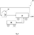
- FIG. 1 schematically shows a phosphorus recovery plant 400 according to an embodiment of the invention.
- the phosphorus recovery plant 400 serves to recover phosphorus from a phosphorus-containing medium, in particular from sewage sludge and / or wastewater, and comprises at least one mobile process unit 100 for the chemical treatment of the phosphorus-containing medium, which is temporarily coupled to a stationary plant 200, which provides the phosphorus-containing medium ,
- a detachable feed line is provided, through which the phosphorus-containing medium from the stationary plant 200 in the mobile processing unit 100 can be inserted.
- a detachable return line is provided between the stationary system 200 and the mobile process unit 100, by means of which the phosphorus-reduced medium from the mobile process unit 100 can be fed back into the stationary system 200, while the recovered phosphorus is in particular in the form of crystalline MAP and / or MAP hexyhydrate is taken.
- a container (not shown) may be provided at the output of the mobile processing unit 100.
- the mobile process unit 100 can be designed as a transportable container with standard dimensions or as a self-propelled vehicle or as a vehicle trailer.
- the stationary plant 200 is a sewage treatment plant.
- the mobile process unit 100 is provided with a collecting tank 202 for sewage sludge and / or Wastewater coupled to the stationary plant 200, which is usually present in such systems.
- the medium to be treated is anaerobically stabilized sewage sludge from various municipal sewage treatment plants, which phosphorus elimination e.g. operate by means of iron and / or aluminum salts. Alternative precipitants are possible.
- the nature of the sewage sludge varies between the individual sewage treatment plants and seasonal.
- Digested sludge has a solids content of 1 wt.% To 5 wt.%, Based on the weight.
- the solids are both inorganic and organic, e.g. Remains of microorganisms of biological wastewater treatment. Under anaerobic conditions, microorganisms convert the slightly fouling portion of the organic matter of the original raw sludge to form digester gas to form sludge, i. stabilized sewage sludge to.
- This type of conventional treatment of sewage sludge takes place in collection containers 202, e.g. Digesters, the sewage treatment plants instead.
- a mobile press unit 300 is coupled to the mobile process unit 100 in order to dehydrate the sewage sludge to be treated in an intermediate step.
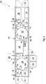
- FIG. 2 shows in plan view an assembly plan of components of a mobile processing unit 100 according to an embodiment of the invention.
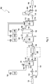
- FIG. 3 shows a corresponding flow diagram of the phosphorus recovery system with mobile processing unit 100 according to an embodiment of the invention.
- the mobile process unit 100 is designed, for example, as a container with a closed housing 102 and respective closable openings 104, 106 on the narrow sides of the housing 102, through which the components can be introduced into the interior of the housing 102.
- a closable opening 106 on a side wall provides access to the interior of the operator's housing 102.
- To move the container on a Trucks are loaded and transported.
- the design as a closed container enables easy transport and protection of the mobile process unit against frost and weather. All components in the housing 102 are designed to resist corrosion.
- a reservoir 110 for a complexing agent e.g. Citric acid
- a reservoir 116 for a precipitant e.g. Magnesium oxide
- the reservoirs 110, 112, 114, 116 are each provided with suitable metering devices, e.g. Dosing pumps, equipped.
- suitable metering devices e.g. Dosing pumps, equipped.
- solids e.g. a screw feeder is provided.
- All containers 130, 150, 170 are suitably designed so that they can be completely emptied, e.g. with sloping floors.
- the return container 130 and the precipitation container 170 have a cylindrical cross-section, the diameter of which fills the interior of the housing 102.
- Stirrers 132, 172 are arranged in the containers 130, 170, so that the respective contents can be moved and homogenized.
- the collecting container 150 arranged therebetween is rectangular.
- the side opening 108 allows access to the central area of the mobile processing unit 100.
- the medium to be treated for example stabilized sewage sludge
- a pump 122 such as a self-priming progressive cavity pump
- the distance to the collecting tank 202 of the sewage treatment plant can typically be up to 25 m.
- the pump is designed for a flow rate of 20-40 m 3 / h, eg 25 m 3 / h.
- the aspirated medium passes via a arranged in a connecting line 124 crushing unit 126, such as a macerator or twin-shaft shredder, in the return container 130th
- the return container 130 is executed closed. In order to allow the highest possible level, the required height is kept as low as possible on the container roof for the agitator 132, e.g. through a horizontally arranged agitator motor. Due to foaming, the redissolution container 130 can not be completely filled. There must be a clearance of around 0.3 m between the tank roof and the liquid level. In order to improve the stirring action of the agitator 132, this may be arranged eccentrically and / or flow breaker may be provided in the container interior. A fan 128 keeps the return container 130 permanently under negative pressure and discharges the extracted air via a pumping line 138 into the atmosphere.
- the remindlbücher matterser 130 is equipped with two pH probes, a conductivity probe, a level sensor and overfill protection.
- the pH is determined in the upper and in the lower region of the re-dissolving tank 130.
- the pH probes are also accessible in operation with filled return tank 130 for periodic inspection and cleaning.
- a sampling point (not shown) allows samples to be taken of the medium at an accessible location.
- a metering pump 134 conveys acid from the reservoir 114, e.g. 78% sulfuric acid, in the gearlette knowinger 130th
- the filling of the redissolution container 130 with the phosphorus-containing medium takes place (via the comminutor 126) with the pump 122.
- the agitator 132 is started at a selectable level and shortly thereafter, the metered addition of the acid is started until a predetermined pH is reached, e.g. a pH of 4.5.
- the acid addition essentially brings the phosphate contained in the medium into solution.
- a readjustment time for the acid dosage must be assumed, for example 30 min, in order to stabilize the pH.
- the need for acid is media-dependent and is for example about 5 liters per cubic meter for digested sludge Digested sludge.
- the time required for the acidification of the medium in the return container 130 can be reduced by suitable measures. This is on the one hand to ensure intensive mixing in the return container 130.
- the addition of the required acid takes place as quickly as possible, for example by an adjustable pilot control with subsequent fine control depending on the pH.
- the addition of acid results in the outgassing of carbon dioxide and a corresponding foaming in the redissolution container 130.
- the medium acidified in the recycling tank 130 is supplied to a press unit 300 after reaching the desired pH, e.g. a chamber filter press, which may be externally coupled.
- the press unit 300 is connected to the mobile processing unit 100 via closable conduits 136 and 142 and is e.g. trained self-absorbed.
- a control and / or regulating device 118 of the mobile process unit 100 is designed, among other things. This is inter alia connected to the sensors and drives of the components of the mobile process unit 100.
- a release signal is output from the mobile processing unit 100 to the press unit 300 and a, preferably electrically controllable, shut-off valve in the connection line 136 is opened.
- the press unit 300 then draws the container contents with a volume flow of initially a value such as the volume flow of the pump 122, for example 25 m 3 / h and then reduces this, for example up to about 3 m 3 / h and leads a solid-liquid Separation through.
- the pump of the press unit 300 turns off, and the shut-off valve in the connecting line 136 is closed. Then, the return container 130 can be filled with the next fresh batch of phosphorus-containing medium.
- the comminution unit 126 and the redissolution container 130 can be provided with a bypass line 125 (FIG. FIG. 3 ) are bypassed and the medium are passed directly into the press unit 300.
- complexing and acidification in the same process step in the redissolution vessel 130 may be accomplished by adding acid (eg sulfuric acid) and a complexing agent (eg citric acid).
- acid eg sulfuric acid
- a complexing agent eg citric acid
- the further steps of separating a high-phosphate portion, separating organic components, precipitating one or more phosphorus compounds by raising the pH of the high-phosphate portion of the medium, and separating the one or more phosphorus compounds from the medium may be the same. If the complexing agent, e.g.
- Citric acid added to the acidification process may contain heavy metal content in the medium squeezed in the press unit 300, e.g. Sewage sludge, to be reduced. This could even become a product flow again and, if the limits are lower, be used for agricultural application, or a product that is generated from sewage sludge would be less heavy metal contaminated.
- the phosphate-rich filtrate from the press unit 300 is conveyed via a pump line 142 by means of a pump 144 into a collecting container 150 back into the mobile process unit 100 and from there by means of a pump 152 via a pump line 154 in a filtration unit 160) promoted.
- the filtration unit 160 may be a separate unit outside unit 100.
- There organic components are removed.
- the purified permeate passes via a connecting line 156 into the precipitation tank 170, while the retentate is passed via the line 162 back into the collecting container.
- the removal of the organic constituents increases the quality of the final product, as organic constituents contribute to undesirable properties, e.g. a discoloration and smell, lead.
- the pump 144 sucks the filtrate from the press unit 300, which is obtained discontinuously.
- the pump 144 can completely aspirate the filtrate so that no buffer container is needed on the press unit 300.
- the resulting volume flow of filtrate corresponds to the initial volume flow of the press unit 300 and then drops accordingly.
- the pump 144 is eg self-priming and dry-run, for example, a diaphragm pump.
- the collecting container 150 has a fill level measurement, an overfill protection, a vent to the atmosphere and a sampling point.
- the volume of the collection container 150 depends on the batch size in the return container 130. For example, depending on the medium, between 0.8 and 0.92 cubic meter of filtrate are produced per cubic meter of digested sludge.
- the filtration unit 160 is e.g. an ultrafiltration unit with a ceramic membrane of small pore size.
- the pump 152 e.g. a centrifugal pump is started when reaching an adjustable level in the reservoir 150.
- the retentate of the filtration unit 160 is returned to the sump 150 via an adjustable pressure spill valve.
- the pump 152 Upon reaching an adjustable minimum level of the sump 150, the pump 152 is turned off.
- the medium remaining in the collection container 150 remains there until the next batch or can be disposed of via a residual emptying.
- the permeate volumetric flow rate is chosen so that the ultrafiltration process is carried out in a desired time, e.g. maximum 30 minutes, completed.
- the medium filtered in the filtration unit 160 is first collected in the precipitation tank 170. After completion of the filtration, the process steps of complexing, precipitation and neutralization and crystallization of the final product are carried out successively, preferably with constant stirring of the agitator 172.
- the precipitation vessel 170 has an agitator 172, a fill level sensor, a pH probe, a conductivity sensor, an overfill prevention device , a vent to the atmosphere and a sampling point.
- the complexing is carried out because the acidification in the gearlette knowner 130 in addition to phosphate ions and metal ions, such as iron, aluminum, calcium and magnesium, are redissolved.
- a complexing agent an acid, eg citric acid, is added from the storage tank 110 into the precipitation tank 170.
- the complexing agent has the task of binding these metals and preventing them from later failing again as metal phosphates.
- the reference value for the citric acid dosing pump may be based on an average consumption of 50% citric acid of 4.6 liters per cubic meter of digested sludge. In a batch size of 7 m 3 thus 32 liters have to be added in a period of a maximum of 10 min.
- the volume content corresponds to that of the re-dissolving tank 130.
- the pH value and the electrical conductivity are measured in the lower tank area. The probes and sensors are also accessible when the container is filled for regular inspection and cleaning.
- the addition of the precipitating agent takes place from the reservoir 116 via a metering device 178, for example a screw conveyor dosing device.
- Magnesium is added to the medium in a molar ratio to ortho-phosphate of 1.5: 1 (Mg: PO 4 ).
- the concentration of orthophosphate is determined analytically in a sample taken at the precipitation tank 170.
- the magnesium oxide is added intermittently at intervals. For the design of the solids dosage can be assumed that a consumption of magnesium oxide of 0.9 kg per cubic meter of digested sludge. For a batch size of 7 m 3 digested sludge this corresponds to 6.3 kg magnesium oxide. This amount is added within a maximum of 30 min.
- the neutralization can take place without waiting time, for example by adding sodium hydroxide solution.
- sodium hydroxide solution By adding the sodium hydroxide solution, the pH in the precipitation tank 170 is raised to 8.2.
- Optimum MAP precipitation occurs in this region, with crystallization starting at pH 6.0.
- the need for caustic soda (25%) is approximately 5.6 liters per cubic meter of processed sludge.
- the target pH is set within, for example, 30 minutes. This is followed by an agglomeration time, for example 60 min, during which MAP crystallizes out. During this time, the container contents are stirred further.
- the medium with the crystallized MAP crystals for dewatering by means of a pump 176 via a pumping line 174 in the separator 180 is passed.
- the separating device 180 is designed, for example, as a motor-driven sieve in the form of a dewatering sieve with a vibration motor.
- the mesh size is for example 100 microns, but can also be converted if necessary.
- the dewatered product eg in the form of MAP crystals, may be placed in a container 190 (FIG. FIG. 3 ), which can conveniently absorb the amount of product of a batch completely. Approximately 3.9 kg of MAP hexahydrate are produced per cubic meter of digested sludge. A batch of 7 m 3 digested sludge thus gives about 27 kg of MAP or MAP hexahydrate.
Landscapes
- Life Sciences & Earth Sciences (AREA)
- Hydrology & Water Resources (AREA)
- Engineering & Computer Science (AREA)
- Environmental & Geological Engineering (AREA)
- Water Supply & Treatment (AREA)
- Chemical & Material Sciences (AREA)
- Organic Chemistry (AREA)
- Treatment Of Sludge (AREA)
- Removal Of Specific Substances (AREA)
Abstract
Description
- Die Erfindung betrifft eine Phosphorrückgewinnungsanlage und ein Verfahren zum Betreiben einer Phosphorrückgewinnungsanlage.
- Phosphor ist für das Pflanzenwachstum von großer Bedeutung. Mehr als 90% der Rohphosphate weltweit werden zu Dünger verarbeitet, wobei dieser Phosphor aus geogenen Lagerstätten stammt, deren Reserven sich in absehbarer Zeit erschöpfen können. Häufig sind derartige Rohphosphate mit Schadstoffen belastet, die mit zunehmender Abbautiefe im Gehalt zunehmen.
- Zunehmend gewinnt die Phosphorrückgewinnung als Phosphorquelle an Bedeutung. Hierzu sind unterschiedliche Verfahren Gegenstand von wissenschaftlichen Untersuchungen an Pilotanlagen. Eine gezielte Phosphorelimination beispielsweise im Abwasser erfolgt entweder über eine chemisch-physikalische oder über eine biologische Phosphorelimination. Beim bekannten "Stuttgarter Verfahren" wird aus anaerob stabilisiertem Klärschlamm Phosphor in Form von Magnesium-Ammonium-Phosphat (MAP) gewonnen.
- Ein anderes Verfahren wird in der
DE 10 2011 016 826 A1 beschrieben. Dort erfolgt die Rückgewinnung von Phosphor aus Abwasser mit Hilfe eines Calcium-Silicat-Hydrat als Kristallisationssubstrat im kontinuierlichen Betrieb in einer Phosphorrückgewinnungsanlage. Diese umfasst einen im Wesentlichen zylindrischen Rührreaktor sowie einen Sedimentationsbehälter, wobei der Rührreaktor in eine im oberen Teil befindliche Ruhezone und eine im unteren Teil befindliche Reaktionszone unterteilt ist. Der Rührreaktor umfasst eine Rührvorrichtung und einen Zulauf, die beide mittig in der Reaktionszone angeordnet sind. Der Rührreaktor ist dem Sedimentationsbehälter derart vorgeschaltet, dass der Ablauf aus der Ruhezone des Rührreaktors als Zulauf in die mittlere Höhe des Sedimentationsbehälters verbunden ist. - Aufgabe der Erfindung ist es, eine effiziente und kommerziell einsetzbare Phosphorrückgewinnungsanlage zu schaffen.
- Eine weitere Aufgabe ist die Schaffung eines Verfahrens zum Betreiben einer Phosphorrückgewinnungsanlage.
- Die Aufgaben werden durch die Merkmale der unabhängigen Ansprüche gelöst. Günstige Ausgestaltungen und Vorteile der Erfindung ergeben sich aus den weiteren Ansprüchen, der Beschreibung und der Zeichnung.
- Die Erfindung geht aus von einer Phosphorrückgewinnungsanlage zur Rückgewinnung von Phosphor aus einem phosphorhaltigen Medium, insbesondere aus Klärschlamm und/oder Abwasser.
- Es wird vorgeschlagen, dass wenigstens eine mobile Prozesseinheit zur chemischen Behandlung des phosphorhaltigen Mediums vorgesehen ist, welche zeitweise an eine stationäre Anlage gekoppelt ist, welche das phosphorhaltige Medium bereitstellt. Die mobile Prozesseinheit umfasst in Prozessrichtung des Mediums einen Rücklösebehälter zum Rücklösen von Phosphat im zugeführten phosphorhaltigen Medium, einen Sammelbehälter zum Sammeln des teilweise gereinigten Mediums und einen Fällungsbehälter zum Ausfällen eines phosphatreichen Produkts.
- Insbesondere können Rücklösebehälter und Fällungsbehälter einen maximalen Raum innerhalb des Gehäuses der mobilen Prozesseinheit einnehmen.
- Vorteilhaft kann insbesondere an bestehenden Kläranlagen eine Phosphorrückgewinnung erfolgen, ohne nennenswerte bauliche Veränderungen an der stationären Anlage vornehmen zu müssen. So kann die mobile Prozesseinheit an einen üblicherweise bereits vorhandenen stationären Sammelbehälter für Klärschlamm angekoppelt werden. In einem solchen stationären Sammelbehälter wird Klärschlamm gesammelt, um anschließend entsorgt zu werden. Häufig werden für derartige Behälter oder sonstige Komponenten der stationären Anlage sehr preiswerte Materialien eingesetzt, die sich für eine chemische Behandlung des darin befindlichen Klärschlamms nicht eignen, da sie beispielsweise nicht säureresistent sind. Die mobile Prozesseinheit erlaubt unabhängig vom Zustand oder der chemischen Eignung von Komponenten der stationären Anlage eine hocheffiziente chemisch-physikalische Behandlung des Klärschlamms. Weiterhin braucht der Betrieb der Kläranlage nicht unterbrochen werden, sondern kann ungestört weiterlaufen, während der gesammelte Klärschlamm behandelt wird.
- Die Prozesseinheit kann mit allen notwendigen Mitteln und Komponenten ausgestattet sein, die für die Klärschlammbehandlung notwendig sind, unabhängig vom Zustand der stationären Anlage.
- Dadurch, dass die Prozesseinheit mobil ist, kann diese, ja nach Bedarf, an einer Vielzahl von stationären Anlagen eingesetzt werden und von einer zur anderen stationären Anlage verbracht werden.
- Nach einer günstigen Ausgestaltung kann zwischen der stationären Anlage und der mobilen Prozesseinheit eine lösbare Einspeiseleitung vorgesehen sein, durch welche das phosphorhaltige Medium aus der stationären Anlage in die mobile Prozesseinheit einführbar ist. Hierzu können erprobte Leitungsmaterialien, Kupplungen und Verschlüsse, wie sie etwa für Tankwagen üblich sind, eingesetzt werden.
- Nach einer günstigen Ausgestaltung kann zwischen der stationären Anlage und der mobilen Prozesseinheit eine lösbare Rückspeiseleitung vorgesehen sein, durch welche das im Phosphorgehalt reduzierte Medium aus der mobilen Prozesseinheit in die stationäre Anlage rückspeisbar ist. Damit ist abgereinigtes Abwasser wieder für die stationäre Anlage verfügbar, deren Effizienz damit erhöht werden kann.
- Nach einer günstigen Ausgestaltung kann die mobile Prozesseinheit einen transportablen Container oder ein selbstfahrendes Fahrzeug oder einen Fahrzeuganhänger umfassen. Es können Standardmodule verwendet werden, die für den Straßentransport geeignet sind. Diese weisen standardisierte Abmessungen auf, so dass eine Ausrüstung der mobilen Prozesseinheit ebenso standardisiert sein kann. Ein Fahrzeuganhänger oder ein Container kann an der stationären Anlage zeitweise abgestellt werden, während das Zugfahrzeug anderweitig eingesetzt wird, solange die Phosphorrückgewinnung dauert. Ein Fahrzeug kann nach Abschluss des Vorgangs schneller wieder von der stationären Anlage entfernt werden. Die mobile Prozesseinheit kann unproblematisch von einem Einsatz an einer stationären Anlage zum nächsten Einsatz an einer anderen stationären Anlage transportiert werden. In der mobilen Prozesseinheit können auch notwendige Analyseeinrichtungen vorgesehen sein, welche zur geeigneten Zudosierung von Chemikalien in verschiedenen Verfahrensschritten der Phosphorrückgewinnung notwendig sind.
Ebenso können geeignete Sicherheitseinrichtungen für Bedienpersonal und für Komponenten an Bord der mobilen Prozesseinheit vorgesehen sein. - Nach einer günstigen Ausgestaltung kann an die mobile Prozesseinheit eine mobile Presseneinheit ankoppelbar sein. Hier kann ausgenutzt werden, dass derartige mobile Presseneinheiten für Entwässerungsaufgaben bei Klärschlamm verfügbar sind. Diese können nunmehr auch bei der Phosphorrückgewinnung eingesetzt werden. Alternativ oder zusätzlich kann eine Presseneinheit auch in der mobilen Prozesseinheit vorgesehen sein oder eine stationäre Presseneinheit sein.
- Nach einer günstigen Ausgestaltung kann die stationäre Anlage eine Kläranlage sein. Insbesondere kann die mobile Prozesseinheit mit einem Sammelbehälter für Klärschlamm und/oder Abwasser der stationären Anlage gekoppelt sein. Es können an der Kläranlage vorhandene Komponenten genutzt werden und durch die wenigstens zeitweise ankoppelbare mobile Prozesseinheit Klärschlamm als effiziente Quelle für eine Phosphorrückgewinnung genutzt werden. Der Betrieb der Kläranlage kann ungestört parallel dazu weiterlaufen.
- Nach einer günstigen Ausgestaltung kann die mobile Prozesseinheit zur Kopplung mit einer Vielzahl von stationären Anlagen vorgesehen sein. Eine einzige mobile Prozesseinheit kann kostengünstig überregional an verschiedenen stationären Anlagen eingesetzt werden.
- Nach einem weiteren Aspekt der Erfindung wird eine mobile Prozesseinheit für eine oder mehrere Phosphorrückgewinnungsanlagen vorgeschlagen, die insbesondere einer oder mehreren Phosphorrückgewinnungsanlagen zugeordnet ist, wobei in einem Gehäuse der mobilen Prozesseinheit ein Rücklösebehälter zum Rücklösen von Phosphat in einem zugeführten phosphorhaltigen Medium, ein Sammelbehälter zum Sammeln des teilweise gereinigten Mediums und ein Fällungsbehälter zum Ausfällen eines phosphatreichen Produkts vorgesehen ist.
- Die mobile Prozesseinheit kann insbesondere in einer Phosphorrückgewinnungsanlage eingesetzt werden, wie sie vorstehend beschrieben ist. Insbesondere kann die mobile Prozesseinheit zeitweise an eine stationäre Kläranlage angekoppelt werden. Bei Bedarf kann die mobile Prozesseinheit zu weiteren Kläranlagen bewegt werden.
- Die mobile Prozesseinheit kann z.B. ein Container sein, der mit üblichen Lastkraftwagen transportiert werden kann, in dessen Inneren die notwendigen Komponenten für die chemische Behandlung des Mediums angeordnet sind. Optional kann eine Presseneinheit vorgesehen sein, insbesondere eine Kammerfilterpresse, die ebenfalls als mobile Einheit ausgebildet sein kann und die zeitweise mit der mobilen Prozesseinheit gekoppelt sein kann.
- Der Rücklösebehälter ist zweckmäßigerweise mit einer Dosiereinrichtung, z.B. einer Dosierpumpe, für Säure, z.B. Schwefelsäure, gekoppelt. Vorteilhaft kann so viel Säure zudosiert werden, bis ein gewünschter pH-Wert eingestellt ist. Mit Vorteil ist ein Rührwerk im Rücklösebehälter vorgesehen, um das darin enthaltene Medium und die Säure zu homogenisieren. Es können sowohl eine Probenentnahmestelle als auch Sensoren zur Prozesskontrolle, z.B. pH-Sonden, Leitfähigkeitssensoren, Füllstandsensoren etc., am oder im Rücklösebehälter vorgesehen sein. Ferner können Einrichtungen wie Schaumbrecher und dergleichen vorgesehen sein, um ein übermäßiges Schäumen des mit Säure versetzten Mediums zu vermeiden.
- Die mobile Prozesseinheit kann speziell für ihren Einsatzzweck optimiert ausgestattet sein. Durch ihre örtlich flexiblen Einsatzmöglichkeiten amortisieren sich dadurch entstehende Kosten schnell. In der mobilen Prozesseinheit können auch notwendige Analyseeinrichtungen vorgesehen sein, welche zur geeigneten Zudosierung von Chemikalien in verschiedenen Verfahrensschritten der Phosphorrückgewinnung notwendig sind. Ebenso können geeignete Sicherheitseinrichtungen für Bedienpersonal und für Komponenten an Bord der mobilen Prozesseinheit vorgesehen sein.
- Nach einer günstigen Ausgestaltung kann dem Rücklösebehälter in Prozessrichtung eine Zerkleinerungseinheit vorgeschaltet sein. Durch die Zerkleinerungseinheit lassen sich Verzopfungen in den folgenden Verfahrensschritten in der mobilen Prozesseinheit vermeiden und die Entwässerungseigenschaften in einem Zwischenschritt mit einer Presseneinheit, insbesondere einer Kammerfilterpresse, nach der Rücklösung des Phosphats verbessern. Die Zerkleinerungseinheit kann geeignet ausgeführt sein, etwa als Zweiwellenzerkleinerer, Mazerator oder dergleichen.
- Um das Medium in die mobile Prozesseinheit und gegebenenfalls die Zerkleinerungseinheit zu transportieren, kann eine selbstansaugende Pumpe eingesetzt werden, z.B. eine Exzenterschneckenpumpe. Dies erlaubt eine relativ große Saugstrecke bis zu 25 m zwischen einem Sammelbehälter für das phosphorhaltige Medium in der stationären Anlage und der mobilen Prozesseinheit.
- Nach einer günstigen Ausgestaltung kann in Prozessrichtung zwischen dem Rücklösebehälter und dem Sammelbehälter eine Presseneinheit angeordnet oder ankoppelbar sein. Diese kann selbstansaugend ausgeführt sein.
- Der Feststoff kann wieder der stationären Anlage zugeführt werden, während das filtrierte phosphorhaltige Medium weiter in der mobilen Prozesseinheit behandelt wird. Das filtrierte Medium kann mit einer Pumpe, insbesondere mit einer trockenlaufenden Pumpe wie einer Membranpumpe, in den Sammelbehälter befördert werden.
- Denkbar ist, die Zerkleinerungseinheit und/oder den Rücklösebehälter durch eine Bypassleitung zu umgehen. Dies kann je nach Zustand des Ausgangsmaterials des phosphorhaltigen Mediums günstig sein und Zeit sparen. Das Medium kann dann direkt der Presseneinheit zur Entwässerung zugeführt werden. Nach einer günstigen Ausgestaltung kann in Prozessrichtung zwischen Sammelbehälter und dem Fällungsbehälter eine Filtrationseinheit vorgesehen sein. Dies kann insbesondere eine Ultrafiltrationseinheit sein. Die Ultrafiltrationseinheit kann eine keramische Ultrafiltrationsmembran aufweisen, die austauschbar sein kann. Vorteilhaft sind Porenweiten von weniger als 0,1 µm, bevorzugt weniger als 0,05 µm. Die Filtrationseinheit kann auch eine separate Einheit außerhalb der mobilen Prozesseinheit sein.
- Nach einer günstigen Ausgestaltung kann Retentat aus der Filtrationseinheit zurück in den Sammelbehälter der mobilen Prozesseinheit und Permeat aus der Filtrationseinheit in den Fällungsbehälter leitbar sein. Bei dem Retentat wie auch bei dem Permeat handelt es sich um flüssige Medien. Das Permeat ist entwässertes, gereinigtes phosphorhaltiges Medium und kann mit einer Pumpe, insbesondere einer Kreiselpumpe, in den Fällungsbehälter gefördert werden.
- Der Fällungsbehälter ist vorteilhaft mit einer Dosiereinrichtung von Chemikalien gekoppelt. So kann eine Säure zugegeben werden, um Metallionen im phosphorreichen Medium zu komplexieren und als Metallkomplexe zu binden, um zu verhindern, dass bei einer anschließend durchgeführten Fällungsreaktion in unkontrollierter Weise Metallphosphate ausfallen. Die Metallionen können wie die Phosphorionen durch das anfängliche Ansäuern im Rücklösebehälter in das Medium gelangt sein. Nach der Komplexierung der Metalle kann die Zugabe eines Fällungsmittels, insbesondere Magnesiumoxid, erfolgen. Durch eine Zugabe des Fällungsmittels, insbesondere Magnesiumoxid, können Phosphorionen kontrolliert ausgefällt werden.
- Zusätzlich kann ein Neutralisationsmittel zugegeben werden, insbesondere Natronlauge. Vorteilhaft wird dabei ein pH-Wert eingestellt, bei dem eine besonders effiziente Fällungsreaktion erfolgt.
- Vorteilhaft ist der Fällungsbehälter mit einem Rührwerk zum Homogenisieren des Behälterinhalts versehen.
- Nach einer günstigen Ausgestaltung kann zumindest der Sammelbehälter und/oder der Fällungsbehälter eine Probenentnahmestelle aufweisen. Vorteilhaft ist es weiterhin, in den Behältern Sensoren zur Prozessüberwachung vorzusehen. Durch die Probenentnahme kann das Zudosieren von notwendigen Chemikalien möglichst genau erfolgen.
- Nach einer günstigen Ausgestaltung kann an den Fällungsbehälter eine Trennvorrichtung zum Abtrennen von ausgefälltem phosphatreichem Feststoff aus phosphatarmem Medium angeschlossen sein. Das Filtrat enthält eine oder mehrere auskristallisierte Phosphorverbindungen, insbesondere Magnesium-Ammonium-Phosphat, auch bekannt als MAP oder MAP-Hexahydrat. MAP ist auch als Struvit bekannt. Der Begriff "MAP" oder "MAP-Hexahydrat" wird im Kontext der Erfindung pauschal für Magnesium-Ammonium-Phosphat-Verbindungen verwendet. Das abgetrennte wässrige phosphatarme Medium kann wieder der stationären Anlage zugeführt und dort weiterverwertet werden. Die Trennvorrichtung kann ein Sieb sein, insbesondere ein motorbetriebenes Sieb, z.B. ein Entwässerungssieb mit Vibrationsmotor. Die Maschenweite des Siebs kann z.B. bei 100 µm liegen und gegebenenfalls durch eine andere Maschenweite ersetzt werden. Die entwässerten phosphathaltigen Kristalle können in einem Behälter gesammelt werden.
- Vorteilhaft kann aus einem Kubikmeter Klärschlamm knapp 4 kg MAP-Hexahydrat gewonnen werden. Günstigerweise kann die mobile Prozesseinrichtung mit einem Aufnahmevermögen einer Charge von 7 m3 Klärschlamm ausgelegt werden. Dies ist in einem üblichen Containergehäuse realisierbar.
- Nach einem weiteren Aspekt der Erfindung wird ein Verfahren zum Betreiben einer Phosphorrückgewinnungsanlage zur Rückgewinnung von Phosphor aus einem phosphorhaltigen Medium, insbesondere aus Klärschlamm und/oder Abwasser, vorgeschlagen. Das Verfahren ist gekennzeichnet durch die Schritte:
- (a) Bereitstellen eines phosphorhaltigen Mediums in einer stationären Anlage;
- (b) Ankoppeln einer mobilen Prozesseinheit an die stationäre Anlage;
- (c) Einleiten des Mediums in die mobile Prozesseinheit;
- (d) Extrahieren und/oder Kristallisieren des Phosphatanteils aus dem Medium in der mobilen Prozesseinheit.
- Die stationäre Anlage kann insbesondere eine kommunale Kläranlage sein. Der Phosphatanteil kann vorteilhaft in Form von MAP / MAP-Hexahydrat gewonnen werden.
- Die mobile Prozesseinheit kann z.B. ein Container sein, der mit üblichen Lastkraftwagen transportiert werden kann, in dessen Inneren die notwendigen Komponenten für die chemische Behandlung des Mediums angeordnet sind. Optional kann eine Presseneinheit vorgesehen sein, insbesondere eine Kammerfilterpresse, die ebenfalls als mobile Einheit ausgebildet sein kann und die zeitweise mit der mobilen Prozesseinheit gekoppelt sein kann.
- Nach einer günstigen Ausgestaltung können die Schritte in der Prozesseinheit durchgeführt werden:
- (i) Ansäuern des Mediums auf einen gewünschten pH-Wert;
- (ii) Abtrennen eines phosphatreichen Anteils des Mediums aus dem angesäuerten Medium;
- (iii) Abtrennen von organischen Bestandteilen aus dem phosphatreichen Anteil des Mediums;
- (iv) Komplexierung von Metallionen im phosphatreichen Anteil des Mediums;
- (v) Ausfällen von ein oder mehreren Phosphorverbindungen durch Erhöhen des pH-Werts des phosphatreichen Anteils des Mediums; und
- (vi) Abtrennen der ein oder mehreren Phosphorverbindungen aus dem Medium.
- Alternativ kann statt einem getrennten Ansäuern des Mediums in einem Schritt und einer Komplexierung von Metallionen in einem separaten späteren Schritt die Komplexierung und das Ansäuern im gleichen Verfahrensschritt erfolgen, indem Säure und ein Komplexbildner zugegeben werden. Die weiteren Schritte Abtrennen eines phosphatreichen Anteils, Abtrennen von organischen Bestandteilen, Ausfällen von ein oder mehreren Phosphorverbindungen durch Erhöhen des pH-Werts des phosphatreichen Anteils des Mediums und Abtrennen der ein oder mehreren Phosphorverbindungen aus dem Medium können gleich bleiben. Beispielsweise kann im kombinierten Schritt Schwefelsäure zum Ansäuern und Zitronensäure als Komplexbildner zugegeben werden.
- Wird der Komplexbildner, z.B. Zitronensäure, gleich beim Ansäuervorgang beigegeben (z.B. Zugabe von Schwefelsäure und Zitronensäure), kann der Gehalt an Schwermetallen im abgepressten Medium, z.B. Klärschlamm, vermindert werden. Dieser könnte sogar wieder zum Produktstrom werden und, wenn entsprechende Grenzwerte unterschritten sind, für eine landwirtschaftliche Ausbringung genutzt werden, oder aber ein Produkt, das aus dem Klärschlamm generiert wird, wäre weniger schwermetallbelastet.
- Das Ansäuern dient zum Rücklösen von Phosphor aus im Medium, z.B. Klärschlamm, enthaltenen Metallphosphaten und wird vorteilhaft bei einem pH-Wertbereich von 4 bis 4,5 durchgeführt. Das Medium kann dabei zum Homogenisieren bewegt werden mit einer Einwirkzeit nach Erreichen eines stabilen pH-Endwerts von mindestens 15 min bis zu 60 min, vorzugsweise etwa 30 min.
- Vorteilhaft kann das Abtrennen des phosphatreichen Anteils des Mediums aus dem angesäuerten Medium in einer Presseneinheit erfolgen, welche das ganze Volumen des Rücklösebehälters aufnehmen kann, so dass der Rücklösebehälter wieder mit frischem Medium aus der stationären Anlage befüllt werden kann. Auf diese Weise ist ein effizienter Batchbetrieb möglich.
- Das Abtrennen von organischen Bestandteilen aus dem phosphatreichen Anteil des Mediums kann vorteilhaft mittels Ultrafiltration erfolgen.
- Das Ausfällen von ein oder mehreren Phosphorverbindungen, insbesondere MAP oder MAP-Hexahydrat, kann durch Erhöhen des pH-Werts des phosphatreichen Anteils des Mediums erfolgen. Hierzu wird eine Base zugegeben, insbesondere Natronlauge.
- Dabei kann vor der Fällungsreaktion zunächst ein Komplexieren von unerwünschten Metallionen erfolgen, insbesondere mittels Zitronensäure in stöchiometrischem Verhältnis von 1:1 bezogen auf das Verhältnis von Zitronensäure zu Metall. Vorteilhaft ist eine Kontaktzeit von mindestens 15 min bis höchstens 60 min, vorzugsweise 30 min. Dies vermeidet ein späteres Ausfällen von unerwünschtem Metallphosphat. Als Fällungsmittel kann Magnesiumoxid zugegeben werden. Vorteilhaft ist ein Überschuss von Magnesiumoxid von 1,5 : 1 bezogen auf das Verhältnis von Magnesium zu Phosphat im Fällungsbehälter.
- Durch Erhöhen des pH-Werts erfolgt die Fällungsreaktion besonders effizient. So setzt die MAP-Fällung bereits bei einem pH-Wert von 6 ein und erreicht bei einem pH-Wert von 8,2 ein Maximum. Vorteilhaft ist eine Zugabe von 5-6 Litern Natronlauge (25%ig) pro Kubikmeter behandeltem Klärschlamm. Vorzugsweise wird der pH-Wert innerhalb von 30 min eingestellt, mit einer darauffolgenden Agglomerationszeit von 60 min. Zweckmäßigerweise wird der Behälterinhalt in dieser Zeit gerührt.
- Das Abtrennen der ein oder mehreren Phosphorverbindungen wie MAP und/oder MAP-Hexahydrat, aus dem Medium kann mit einer Siebanlage erfolgen.
- Nach einer günstigen Ausgestaltung kann das Abtrennen des phosphatreichen Anteils des Mediums aus dem angesäuerten Medium außerhalb der mobilen Prozesseinheit durchgeführt werden, insbesondere in einer angekoppelten Kammerfilterpresse.
- Weitere Vorteile ergeben sich aus der folgenden Zeichnungsbeschreibung. In den Zeichnungen sind Ausführungsbeispiele der Erfindung dargestellt. Die Zeichnungen, die Beschreibung und die Ansprüche enthalten zahlreiche Merkmale in Kombination. Der Fachmann wird die Merkmale zweckmäßigerweise auch einzeln betrachten und zu sinnvollen weiteren Kombinationen zusammenfassen.
-
- Fig. 1
- schematisch eine Phosphorrückgewinnungsanlage nach einem Ausführungsbeispiel der Erfindung;
- Fig. 2
- in Draufsicht einen Aufstellungsplan von Komponenten einer mobilen Prozesseinheit nach einem Ausführungsbeispiel der Erfindung; und
- Fig. 3
- ein Fließschema einer Phosphorrückgewinnungsanlage nach einem Ausführungsbeispiel der Erfindung.
- In den Figuren sind gleichartige oder gleichwirkende Komponenten mit gleichen Bezugszeichen beziffert. Die Figuren zeigen lediglich Beispiele und sind nicht beschränkend zu verstehen.
- Im Folgenden verwendete Richtungsterminologie mit Begriffen wie "links", "rechts", "oben", "unten", "davor" "dahinter", "danach" und dergleichen dient lediglich dem besseren Verständnis der Figuren und soll in keinem Fall eine Beschränkung der Allgemeinheit darstellen. Die dargestellten Komponenten und Elemente, deren Auslegung und Verwendung können im Sinne der Überlegungen eines Fachmanns variieren und an die jeweiligen Anwendungen angepasst werden.
-
Figur 1 zeigt schematisch eine Phosphorrückgewinnungsanlage 400 nach einem Ausführungsbeispiel der Erfindung. Die Phosphorrückgewinnungsanlage 400 dient zur Rückgewinnung von Phosphor aus einem phosphorhaltigen Medium, insbesondere aus Klärschlamm und/oder Abwasser, und umfasst wenigstens eine mobile Prozesseinheit 100 zur chemischen Behandlung des phosphorhaltigen Mediums, welche zeitweise an eine stationäre Anlage 200 gekoppelt ist, welche das phosphorhaltige Medium bereitstellt. - Zwischen der stationären Anlage 200 und der mobilen Prozesseinheit 100 ist eine lösbare Einspeiseleitung vorgesehen, durch welche das phosphorhaltige Medium aus der stationären Anlage 200 in die mobile Prozesseinheit 100 einführbar ist. Ferner ist zwischen der stationären Anlage 200 und der mobilen Prozesseinheit 100 eine lösbare Rückspeiseleitung vorgesehen, durch welche das im Phosphorgehalt reduzierte Medium aus der mobilen Prozesseinheit 100 in die stationäre Anlage 200 rückspeisbar ist, während der zurückgewonnene Phosphor insbesondere in Form von kristallinem MAP und/oder MAP-Hexyhydrat entnommen wird. Dazu kann ein Behälter (nicht dargestellt) am Ausgang der mobilen Prozesseinheit 100 vorgesehen sein.
- Die mobile Prozesseinheit 100 kann als transportabler Container mit Standardabmessungen oder als selbstfahrendes Fahrzeug oder als Fahrzeuganhänger ausgebildet sein.
- Im Ausführungsbeispiel ist die stationäre Anlage 200 eine Kläranlage. Die mobile Prozesseinheit 100 ist mit einem Sammelbehälter 202 für Klärschlamm und/oder Abwasser der stationären Anlage 200 gekoppelt, der üblicherweise bei derartigen Anlagen vorhanden ist.
- Das zu behandelnde Medium ist anaerob stabilisierter Klärschlamm von verschiedenen kommunalen Kläranlagen, welche Phosphorelimination z.B. mittels Eisen- und/oder Aluminiumsalzen betreiben. Alternative Fällungsmittel sind möglich. Die Beschaffenheit des Klärschlamms variiert zwischen den einzelnen Kläranlagen und jahreszeitlich bedingt.
- Faulschlamm hat einen Feststoffgehalt von 1 Gew.% bis 5 Gew.%, bezogen auf das Gewicht. Die Feststoffe sind sowohl anorganische als auch organische Stoffe, z.B. Reste von Mikroorganismen einer biologischen Abwasserreinigung. Unter anaeroben Bedingungen setzen Mikroorganismen den leicht faulenden Anteil der organischen Substanz des ursprünglichen Rohschlamms unter Bildung von Faulgas zu Faulschlamm, d.h. stabilisiertem Klärschlamm, um. Diese Art der konventionellen Behandlung von Klärschlamm findet in Sammelbehältern 202, z.B. Faultürmen, der Kläranlagen statt.
- Im Faulschlamm befindet sich Phosphor u.a. in Form von Metallphosphaten [Me-PO4] gebunden. Um die unterschiedlichen Phosphorverbindungen in gelöstes ortho-Phosphat [PO4-P] zu bringen, wird der anaerob stabilisierte Klärschlamm angesäuert.
- An die mobile Prozesseinheit 100 ist eine mobile Presseneinheit 300 angekoppelt, um in einem Zwischenschritt den zu behandelnden Klärschlamm zu entwässern.
-
Figur 2 zeigt in Draufsicht einen Aufstellungsplan von Komponenten einer mobilen Prozesseinheit 100 nach einem Ausführungsbeispiel der Erfindung.Figur 3 zeigt ein entsprechendes Fließschema der Phosphorrückgewinnungsanlage mit mobiler Prozesseinheit 100 nach einem Ausführungsbeispiel der Erfindung. - Die mobile Prozesseinheit 100 ist z.B. als Container ausgebildet mit einem geschlossenen Gehäuse 102 und jeweils verschließbaren Öffnungen 104, 106 an den Schmalseiten des Gehäuses 102, durch welche die Komponenten in das Innere des Gehäuses 102 eingebracht werden können. Eine verschließbare Öffnung 106 an einer Seitenwand dient dem Zugang ins Innere des Gehäuses 102 für Bedienpersonal. Zur Ortsveränderung kann der Container auf einen Lastkraftwagen geladen und transportiert werden. Die Ausführung als geschlossener Container ermöglicht den einfachen Transport und den Schutz der mobilen Prozesseinheit vor Frost und Witterungseinflüssen. Alle Komponenten im Gehäuse 102 sind korrosionsresistent ausgelegt.
- In Prozessrichtung des Mediums, die im Wesentlichen von der einen Schmalseite zur gegenüberliegenden Schmalseite des Gehäuses 102 verläuft, ist ein Rücklösebehälter 130 zum Rücklösen von Phosphat im zugeführten phosphorhaltigen Medium, ein Sammelbehälter 150 zum Sammeln des teilweise gereinigten Mediums, ein Fällungsbehälter 170 zum Ausfällen eines phosphatreichen Produkts und eine Trennvorrichtung 180 angeordnet. Außerhalb des Gehäuses 102 sind ein Vorratsbehälter 112 für Säure, z.B. Schwefelsäure, und ein Vorratsbehälter 114 für eine Lauge, z.B. Natronlauge, angeordnet, die in den Rücklösebehälter 130 (Schwefelsäure) und in den Fällungsbehälter 170 (Natronlauge) zudosiert werden können. Dazu sind geeignete Durchführungen durch das Gehäuse 102 vorgesehen (nicht dargestellt). Innerhalb des Gehäuses ist ein Vorratsbehälter 110 für einen Komplexbildner, z.B. Zitronensäure und ein Vorratsbehälter 116 für ein Fällungsmittel, z.B. Magnesiumoxid, angeordnet.
- Die Vorratsbehälter 110, 112, 114, 116 sind jeweils mit geeigneten Dosiereinrichtungen, z.B. Dosierpumpen, ausgestattet. Für die Zudosierung von Feststoffen ist z.B. ein Förderschneckendosierer vorgesehen
- Alle Behälter 130, 150, 170 sind zweckmäßigerweise so ausgebildet, dass diese vollständig entleert werden können, z.B. mit Schrägböden.
- Der Rücklösebehälter 130 und der Fällungsbehälter 170 weisen einen zylinderförmigen Querschnitt auf, dessen Durchmesser das Innere des Gehäuses 102 ausfüllt. In den Behältern 130, 170 sind jeweils Rührwerke 132, 172 angeordnet, so dass der jeweilige Inhalt bewegt und homogenisiert werden kann.
- Der dazwischen angeordnete Sammelbehälter 150 ist rechteckig ausgebildet. Die seitliche Öffnung 108 erlaubt den Zugang zum mittleren Bereich der mobilen Prozesseinheit 100.
- Das zu behandelnde Medium, z.B. stabilisierter Klärschlamm, wird über eine Pumpleitung 120 in den Prozessbereich der mobilen Prozesseinheit 100 mittels einer Pumpe 122, z.B. einer selbstansaugenden Exzenterschneckenpumpe, angesaugt. Der Abstand zum Sammelbehälter 202 der Kläranlage kann typischerweise bis zu 25 m betragen. Die Pumpe ist z.B. auf einen Volumenstrom von 20-40 m3/h, z.B. 25 m3/h ausgelegt. Das angesaugte Medium gelangt über eine in einer Verbindungsleitung 124 angeordneten Zerkleinerungseinheit 126, z.B. einen Mazerator oder Zweiwellenzerkleinerer, in den Rücklösebehälter 130.
- Der Rücklösebehälter 130 ist geschlossen ausgeführt. Um einen möglichst hohen Füllstand zu ermöglichen, wird die benötigte Höhe auf dessen Behälterdach für das Rührwerk 132 möglichst gering gehalten, z.B. durch einen horizontal angeordneten Rührwerkmotor. Aufgrund von Schaumbildung kann der Rücklösebehälter 130 nicht vollständig gefüllt werden. Zwischen Behälterdach und Flüssigkeitsspiegel muss ein Abstand von rund 0,3 m eingehalten werden. Um die Rührwirkung des Rührwerks 132 zu verbessern, kann dieses exzentrisch angeordnet sein und/oder Strömungsbrecher im Behälterinnern vorgesehen sein. Ein Ventilator 128 hält den Rücklösebehälter 130 permanent unter Unterdruck und entlässt die abgesaugte Luft über eine Pumpleitung 138 in die Atmosphäre. Der Rücklösebehälter 130 ist mit zwei pH-Sonden, einer Leitfähigkeitssonde, einem Füllstandsensor sowie einer Überfüllsicherung ausgestattet. Der pH-Wert wird im oberen und im unteren Bereich des Rücklösebehälters 130 bestimmt. Die pH-Sonden sind auch im Betrieb bei befülltem Rücklösebehälter 130 für regelmäßige Inspektion und Reinigung zugänglich. Eine Probenentnahmestelle (nicht dargestellt) ermöglicht die Entnahme von Proben des Mediums an einer zugänglichen Stelle. Eine Dosierpumpe 134 befördert Säure aus dem Vorratsbehälter 114, z.B. 78%-ige Schwefelsäure, in den Rücklösebehälter 130.
- Die Befüllung des Rücklösebehälters 130 mit dem phosphorhaltigen Medium erfolgt (über den Zerkleinerer 126) mit der Pumpe 122. Das Rührwerk 132 wird ab einem wählbaren Füllstand gestartet und kurz darauf mit der Zudosierung der Säure begonnen, bis ein vorgegebener pH-Wert erreicht ist, z.B. ein pH-Wert von 4,5. Durch die Säurezugabe wird im Wesentlichen das im Medium enthaltene Phosphat in Lösung gebracht.
- Wegen der Puffereigenschaften des Mediums ist nach erstmaligem Erreichen des Zielwerts des pH-Werts von einer Nachregelzeit für die Säuredosierung auszugehen, z.B. 30 min, um den pH-Wert zu stabilisieren. Der Bedarf an Säure ist medienabhängig und beträgt z.B. für Faulschlamm ca. 5 Liter pro Kubikmeter Faulschlamm. Die benötigte Zeitdauer für das Ansäuern des Mediums im Rücklösebehälter 130 kann durch geeignete Maßnahmen reduziert werden. Dies ist zum einen die Sicherstellung einer intensiven Durchmischung im Rücklösebehälter 130. Außerdem erfolgt die Zudosierung der benötigten Säure möglichst rasch, z.B. durch eine einstellbare Vorsteuerung mit anschließender Feinregelung abhängig vom pH-Wert. Durch die Säurezugabe kommt es zum Ausgasen von Kohlenstoffdioxid und einer entsprechenden Schaumbildung im Rücklösebehälter 130.
- Das im Rücklösebehälter 130 angesäuerte Medium wird nach Erreichen des gewünschten pH-Werts einer Presseneinheit 300 zugeführt, z.B. einer Kammerfilterpresse, die extern angekoppelt sein kann. Die Presseneinheit 300 ist über verschließbare Rohrleitungen 136 und 142 mit der mobilen Prozesseinheit 100 verbunden und ist z.B. selbstansaugend ausgebildet. Für eine Kommunikation der mobilen Prozesseinheit 100 und der Presseneinheit 300 sind entsprechende Datenleitungen zwischen den Einheiten 100, 300 vorgesehen. Hierzu ist eine Steuer- und/oder Regeleinrichtung 118 der mobilen Prozesseinheit 100 unter anderem ausgebildet. Diese ist unter anderem mit den Sensoren und Antrieben der Komponenten der mobilen Prozesseinheit 100 verbunden.
- Ist der gewünschte pH-Wert am Ende der Nachregelzeit im Rücklösebehälter 130 stabil erreicht, wird ein Freigabesignal von der mobilen Prozesseinheit 100 an die Presseneinheit 300 ausgegeben und eine, vorzugsweise elektrisch ansteuerbare, Absperrarmatur in der Verbindungsleitung 136 geöffnet. Die Presseneinheit 300 saugt daraufhin den Behälterinhalt mit einem Volumenstrom von anfangs einem Wert wie dem Volumenstrom der Pumpe 122 an, z.B. 25 m3/h und reduziert diesen dann, z.B. bis auf ca. 3 m3/h und führt eine Fest-Flüssig-Trennung durch. Beim Erreichen eines minimalen Füllstands im Rücklösebehälter 130 schaltet die Pumpe der Presseneinheit 300 ab, und die Absperrarmatur in der Verbindungsleitung 136 wird geschlossen. Daraufhin kann der Rücklösebehälter 130 mit der nächsten frischen Charge phosphorhaltigen Mediums befüllt werden.
- Optional kann die Zerkleinerungseinheit 126 und der Rücklösebehälter 130 mit einer Bypassleitung 125 (
Figur 3 ) umgangen werden und das Medium direkt in die Presseneinheit 300 geleitet werden. - Alternativ kann statt einem getrennten Ansäuern des Mediums in einem Schritt im Rücklösebehälter 130 und einer Komplexierung von Metallionen im Fällungsbehälter 170 in einem separaten späteren Schritt die Komplexierung und das Ansäuern im gleichen Verfahrensschritt im Rücklösebehälter 130 erfolgen, indem Säure (z.B. Schwefelsäure) und ein Komplexbildner (z.B. Zitronensäure) zugegeben werden. Die weiteren Schritte Abtrennen eines phosphatreichen Anteils, Abtrennen von organischen Bestandteilen, Ausfällen von ein oder mehreren Phosphorverbindungen durch Erhöhen des pH-Werts des phosphatreichen Anteils des Mediums und Abtrennen der ein oder mehreren Phosphorverbindungen aus dem Medium können gleich bleiben. Wird der Komplexbildner, z.B. Zitronensäure, gleich beim Ansäuervorgang beigegeben (z.B. Schwefelsäure und Zitronensäure), kann der Gehalt an Schwermetallen in dem in der Presseneinheit 300 abgepressten Medium, z.B. Klärschlamm, vermindert werden. Dieser könnte sogar wieder zum Produktstrom werden und, wenn entsprechende Grenzwerte unterschritten sind, für eine landwirtschaftliche Ausbringung genutzt werden, oder aber ein Produkt, das aus dem Klärschlamm generiert wird, wäre weniger schwermetallbelastet.
- Das phosphatreiche Filtrat aus der Presseneinheit 300 wird über eine Pumpleitung 142 mittels einer Pumpe 144 in einen Sammelbehälter 150 zurück in die mobile Prozesseinheit 100 gefördert und von dort mittels einer Pumpe 152 über eine Pumpleitung 154 in eine Filtrationseinheit 160) gefördert. Optional kann die Filtrationseinheit 160 eine separate Einheit außerhalb Einheit 100 sein. Dort werden organische Bestandteile entfernt. Das gereinigte Permeat gelangt über eine Verbindungsleitung 156 in den Fällungsbehälter 170, während das Retentat über die Leitung 162 zurück in den Sammelbehälter geleitet wird. Das Entfernen der organischen Bestandteile erhöht die Qualität des Endprodukts, da organische Bestandteile zu unerwünschten Eigenschaften, wie z.B. einer Verfärbung und Geruch, führen.
- Die Pumpe 144 saugt das Filtrat aus der Presseneinheit 300 ab, welches diskontinuierlich anfällt. Die Pumpe 144 kann das Filtrat vollständig absaugen, so dass an der Presseneinheit 300 kein Pufferbehälter notwendig ist. Der anfallende Volumenstrom an Filtrat entspricht dem anfänglichen Volumenstrom der Presseneinheit 300 und fällt dann entsprechend ab. Die Pumpe 144 ist z.B. selbstansaugend und trockenlauffähig, beispielsweise eine Membranpumpe.
- Der Sammelbehälter 150 verfügt über eine Füllstandsmessung, eine Überfüllsicherung, eine Entlüftung in die Atmosphäre sowie eine Probenentnahmestelle. Das Volumen des Sammelbehälters 150 richtet sich nach der Chargengröße im Rücklösebehälter 130. Pro Kubikmeter Faulschlamm fallen z.B., abhängig vom Medium, zwischen 0,8 und 0,92 Kubikmeter Filtrat an.
- Die Filtrationseinheit 160 ist z.B. eine Ultrafiltrationseinheit mit einer keramischen Membran geringer Porenweite. Die Pumpe 152, z.B. eine Kreiselpumpe, wird bei Erreichen eines einstellbaren Füllstands im Sammelbehälter 150 gestartet. Das Retentat der Filtrationseinheit 160 wird über ein Überströmventil mit einstellbarem Druck zurück in den Sammelbehälter 150 geleitet. Bei Erreichen eines einstellbaren minimalen Füllstands des Sammelbehälters 150 wird die Pumpe 152 ausgeschaltet. Das im Sammelbehälter 150 verbleibende Medium verbleibt dort bis zur nächsten Charge oder kann über eine Restentleerung entsorgt werden. Der Permeat-Volumenstrom wird so gewählt, dass der Ultrafiltrationsprozess in einer gewünschten Zeit, z.B. maximal 30 min, abgeschlossen ist.
- Das in der Filtrationseinheit 160 filtrierte Medium wird zunächst im Fällungsbehälter 170 gesammelt. Nach Abschluss der Filtration werden aufeinander folgend die Prozessschritte Komplexierung, Fällung und Neutralisation und Kristallisation des Endprodukts durchgeführt, vorzugsweise unter ständigem Rühren des Rührwerks 172. Der Fällungsbehälter 170 verfügt über ein Rührwerk 172, einen Füllstandsensor, eine pH-Sonde, einen Leitfähigkeitssensor, eine Überfüllsicherung, eine Entlüftung in die Atmosphäre sowie eine Probenentnahmestelle.
- Das Komplexieren wird durchgeführt, da durch das Ansäuern im Rücklösebehälter 130 neben Phosphationen auch Metallionen, wie Eisen, Aluminium, Calcium und Magnesium, rückgelöst werden. Als Kompexbildner wird eine Säure, z.B. Zitronensäure, aus dem Vorratsbehälter 110 in den Fällungsbehälter 170 zugegeben. Der Komplexbildner hat die Aufgabe, diese Metalle zu binden und zu verhindern, dass diese später wieder als Metallphosphate ausfallen. Die Dosierung des Komplexbildners hängt von der Konzentration der Metallionen ab. Es wird ein stöchiometrisches Verhältnis von Komplexbildner und Metall eingesetzt (Verhältnis Komplexbildner : Metall = 1:1). Hierfür werden die molaren Mengen der Metalle analytisch nach Probennahme bestimmt. Dies kann z.B. im Rücklösebehälter 130 und/oder im Sammelbehälter 150 und/oder im Fällungsbehälter 170 erfolgen. Die sich daraus ergebende Menge an Komplexbildner wird dem Fällungsbehälter 170 auf einmal zugegeben. Anschließend ist eine Kontaktzeit, z.B. 30 min, für die Reaktion abzuwarten. Als Anhaltswert für die Auslegung der Dosierpumpe für Zitronensäure kann von einem durchschnittlichen Bedarf an 50%-iger Zitronensäure von 4,6 Litern je Kubikmeter Faulschlamm ausgegangen werden. Bei einer Chargengröße von 7 m3 müssen also 32 Liter in einer Zeitspanne von maximal 10 min zudosiert werden. Der Volumeninhalt entspricht dem des Rücklösebehälters 130. Der pH-Wert und die elektrische Leitfähigkeit werden im unteren Behälterbereich gemessen. Die Sonden und Sensoren sind auch bei befülltem Behälter für regelmäßige Inspektion und Reinigung zugänglich.
- Nach der Komplexierung der Metalle erfolgt die Zugabe des Fällungsmittels, z.B. pulverförmiges Magnesiumoxid (92%-ig), aus dem Vorratsbehälter 116 über eine Dosiereinrichtung 178, z.B. ein Förderschneckendosierer. Magnesium wird dem Medium in einem molaren Verhältnis zu ortho-Phosphat von 1,5 : 1 (Mg : PO4) zudosiert. Die Konzentration an ortho-Phosphat wird analytisch in einer am Fällungsbehälter 170 entnommenen Probe bestimmt. Das Magnesiumoxid wird diskontinuierlich in Intervallen zugegeben. Für die Auslegung der Feststoffdosierung kann von einem Verbrauch von Magnesiumoxid von 0,9 kg je Kubikmeter Faulschlamm ausgegangen werden. Bei einer Chargengröße von 7 m3 Faulschlamm entspricht dies 6,3 kg Magnesiumoxid. Diese Menge wird innerhalb von maximal 30 min zugegeben.
- Nach vollständiger Zugabe von Magnesiumoxid kann ohne Wartezeit die Neutralisation erfolgen, z.B. durch Zugabe von Natronlauge. Durch Zugabe der Natronlauge wird der pH-Wert im Fällungsbehälter 170 auf 8,2 angehoben. In diesem Bereich findet eine optimale MAP-Fällung statt, wobei die Kristallisation bei einem pH-Wert von 6,0 einsetzt. Der Bedarf an Natronlauge (25%-ig) liegt ungefähr bei 5,6 Litern pro Kubikmeter behandeltem Faulschlamm. Bei einer Chargengröße von 7 m3 ergibt sich ein Bedarf von 39 Liter Natronlauge. Der Ziel-pH-Wert wird innerhalb von z.B. 30 min eingestellt. Daran schließt sich eine Agglomerationszeit, z.B. 60 min, an, während derer MAP auskristallisiert. In dieser Zeit wird der Behälterinhalt weiter gerührt.
- Nach Abschluss der Agglomerationszeit wird das Medium mit den auskristallisierten MAP-Kristallen zur Entwässerung mittels einer Pumpe 176 über eine Pumpleitung 174 in die Trennvorrichtung 180 geleitet.
- Die Trennvorrichtung 180 ist z.B. als motorbetriebenes Sieb in Form eines Entwässerungssiebs mit Vibrationsmotor ausgeführt. Die Maschenweite beträgt z.B. 100 µm, kann jedoch bei Bedarf auch umgerüstet werden. Das entwässerte Produkt, z.B. in Form von MAP-Kristallen, kann in einem Behälter 190 (
Figur 3 ) gesammelt werden, welcher zweckmäßigerweise die Produktmenge einer Charge vollständig aufnehmen kann. Pro Kubikmeter behandeltem Faulschlamm entstehen etwa 3,9 kg MAP-Hexahydrat. Eine Charge von 7 m3 Faulschlamm ergibt somit rund 27 kg MAP bzw. MAP-Hexahydrat. - Die Beschickung der Trennvorrichtung 180 kann mit einstellbarem Volumenstrom erfolgen, um Entwässerungsergebnisse zu optimieren. Hierfür kann ein Regelventil stromab der Pumpe 176 vorgesehen sein. Das Filtrat der Trennvorrichtung 180 wird im Sumpf des Siebs gesammelt und mittels einer Pumpe 182 über eine Pumpleitung 184 zum Ausgang 186 der mobilen Prozesseinrichtung 100 und zurück in die stationäre Anlage geleitet. Dies kann abhängig vom Füllstand in der Trennvorrichtung erfolgen.
- 100
- mobile Prozesseinheit
- 102
- Gehäuse
- 104
- Öffnung
- 106
- Öffnung
- 108
- Öffnung
- 110
- Vorratsbehälter
- 112
- Vorratsbehälter
- 114
- Vorratsbehälter
- 116
- Vorratsbehälter
- 118
- Regeleinrichtung
- 120
- Pumpleitung
- 122
- Pumpe
- 124
- Verbindungsleitung
- 125
- Bypassleitung
- 126
- Zerkleinerungseinheit
- 128
- Ventilator
- 130
- Rücklösebehälter
- 132
- Rührwerk
- 134
- Dosierpumpe
- 136
- Rohrleitung
- 138
- Pumpleitung
- 142
- Rohrleitung
- 144
- Pumpe
- 150
- Sammelbehälter
- 152
- Pumpe
- 154
- Pumpleitung
- 156
- Verbindungsleitung
- 160
- Filtrationseinheit
- 162
- Leitung
- 170
- Fällungsbehälter
- 172
- Rührwerk
- 174
- Pumpleitung
- 176
- Pumpe
- 178
- Dosiereinrichtung
- 180
- Trennvorrichtung
- 182
- Pumpe
- 184
- Pumpleitung
- 186
- Ausgang
- 190
- Behälter
- 200
- stationäre Anlage
- 202
- Sammelbehälter
- 300
- mobile Presseneinheit
- 400
- Phosphorrückgewinnungsanlage
Claims (20)
- Phosphorrückgewinnungsanlage (400) zur Rückgewinnung von Phosphor aus einem phosphorhaltigen Medium, insbesondere aus Klärschlamm und/oder Abwasser, gekennzeichnet durch wenigstens eine mobile Prozesseinheit (100) zur chemischen Behandlung des phosphorhaltigen Mediums, welche zeitweise an eine stationäre Anlage (200) gekoppelt ist, welche das phosphorhaltige Medium bereitstellt, wobei die mobile Prozesseinheit (100) in Prozessrichtung des Mediums einen Rücklösebehälter (130) zum Rücklösen von Phosphat im zugeführten phosphorhaltigen Medium, einen Sammelbehälter (150) zum Sammeln des teilweise gereinigten Mediums und einen Fällungsbehälter (170) zum Ausfällen eines phosphatreichen Produkts umfasst.
- Phosphorrückgewinnungsanlage nach Anspruch 1, dadurch gekennzeichnet, dass zwischen der stationären Anlage (200) und der mobilen Prozesseinheit (100) eine lösbare Einspeiseleitung vorgesehen ist, durch welche das phosphorhaltige Medium aus der stationären Anlage (200) in die mobile Prozesseinheit (100) einführbar ist.
- Phosphorrückgewinnungsanlage nach Anspruch 1 oder 2, dadurch gekennzeichnet, dass zwischen der stationären Anlage (200) und der mobilen Prozesseinheit (100) eine lösbare Rückspeiseleitung vorgesehen ist, durch welche das im Phosphorgehalt reduzierte Medium aus der mobilen Prozesseinheit (100) in die stationäre Anlage (200) rückspeisbar ist.
- Phosphorrückgewinnungsanlage nach einem der vorhergehenden Ansprüche, dadurch gekennzeichnet, dass die mobile Prozesseinheit (100) einen transportablen Container oder ein selbstfahrendes Fahrzeug oder einen Fahrzeuganhänger umfasst.
- Phosphorrückgewinnungsanlage nach einem der vorhergehenden Ansprüche, dadurch gekennzeichnet, dass an die mobile Prozesseinheit (100) eine mobile Presseneinheit (300) ankoppelbar ist.
- Phosphorrückgewinnungsanlage nach einem der vorhergehenden Ansprüche, dadurch gekennzeichnet, dass die stationäre Anlage (200) eine Kläranlage ist.
- Phosphorrückgewinnungsanlage nach Anspruch 6, dadurch gekennzeichnet, dass die mobile Prozesseinheit (100) mit einem Sammelbehälter (202) für Klärschlamm und/oder Abwasser der stationären Anlage (200) gekoppelt ist.
- Phosphorrückgewinnungsanlage nach einem der vorhergehenden Ansprüche, dadurch gekennzeichnet, dass die mobile Prozesseinheit (100) zur Kopplung mit einer Vielzahl von stationären Anlagen (200) vorgesehen ist.
- Mobile Prozesseinheit (100) für eine Phosphorrückgewinnungsanlage (400), insbesondere nach einem der vorhergehenden Ansprüche, wobei in einem transportablen Gehäuse (102) ein Rücklösebehälter (130) zum Rücklösen von Phosphat im zugeführten phosphorhaltigen Medium, ein Sammelbehälter (150) zum Sammeln des teilweise gereinigten Mediums und ein Fällungsbehälter (170) zum Ausfällen eines phosphatreichen Produkts vorgesehen ist.
- Prozesseinheit nach Anspruch 9, dadurch gekennzeichnet, dass dem Rücklösebehälter (130) in Prozessrichtung eine Zerkleinerungseinheit (126) vorgeschaltet ist.
- Prozesseinheit nach Anspruch 9 oder 10, dadurch gekennzeichnet, dass in Prozessrichtung zwischen dem Rücklösebehälter (130) und dem Sammelbehälter (150) eine Presseneinheit (300) angeordnet oder ankoppelbar ist.
- Prozesseinheit nach einem der Ansprüche 9 bis 11, dadurch gekennzeichnet, dass in Prozessrichtung zwischen Sammelbehälter (150) und dem Fällungsbehälter (170) eine Filtrationseinheit (160) vorgesehen ist.
- Prozesseinheit nach einem der Ansprüche 9 bis 12, dadurch gekennzeichnet, dass Retentat aus der Filtrationseinheit (160) in den Sammelbehälter (150) und Permeat aus der Filtrationseinheit (160) in den Fällungsbehälter (170) leitbar ist.
- Prozesseinheit nach einem der Ansprüche 9 bis 13, dadurch gekennzeichnet, dass zumindest der Sammelbehälter (150) und/oder der Fällungsbehälter (170) eine Probenentnahmestelle aufweisen.
- Prozesseinheit nach einem der Ansprüche 9 bis 14, dadurch gekennzeichnet, dass an den Fällungsbehälter (170) eine Trennvorrichtung (180) zum Abtrennen von ausgefälltem phosphatreichem Feststoff aus phosphatarmem Medium angeschlossen ist.
- Verfahren zum Betreiben einer Phosphorrückgewinnungsanlage (400) zur Rückgewinnung von Phosphor aus einem phosphorhaltigen Medium, insbesondere aus Klärschlamm und/oder Abwasser, gekennzeichnet durch die Schritte:(a) Bereitstellen eines phosphorhaltigen Mediums in einer stationären Anlage (200);(b) Ankoppeln einer mobilen Prozesseinheit (100) an die stationäre Anlage (200);(c) Einleiten des Mediums in die mobile Prozesseinheit (100);(d) Extrahieren und/oder Kristallisieren des Phosphatanteils aus dem Medium in der mobilen Prozesseinheit (100).
- Verfahren nach Anspruch 16, gekennzeichnet durch die Schritte in der Prozesseinheit (100):(i) Ansäuern des Mediums auf einen gewünschten pH-Wert;(ii) Abtrennen eines phosphatreichen Anteils des Mediums aus dem angesäuerten Medium;(iii) Abtrennen von organischen Bestandteilen aus dem phosphatreichen Anteil des Mediums;(iv) Komplexierung von Metallionen im phosphatreichen Anteil des Mediums;(v) Ausfällen von ein oder mehreren Phosphorverbindungen durch Erhöhen des pH-Werts des phosphatreichen Anteils des Mediums; und(vi) Abtrennen der ein oder mehreren Phosphorverbindungen aus dem Medium.
- Verfahren nach Anspruch 16, gekennzeichnet durch die Schritte in der Prozesseinheit (100):(i) Ansäuern des Mediums auf einen gewünschten pH-Wert mit gleichzeitiger Komplexierung von Metallionen im phosphatreichen Anteil des Mediums;(ii) Abtrennen eines phosphatreichen Anteils des Mediums aus dem angesäuerten Medium;(iii) Abtrennen von organischen Bestandteilen aus dem phosphatreichen Anteil des Mediums;(iv) Ausfällen von ein oder mehreren Phosphorverbindungen durch Erhöhen des pH-Werts des phosphatreichen Anteils des Mediums; und(v) Abtrennen der ein oder mehreren Phosphorverbindungen aus dem Medium.
- Verfahren nach Anspruch 17 oder 18, dadurch gekennzeichnet, dass das Abtrennen des phosphatreichen Anteils des Mediums aus dem angesäuerten Medium außerhalb der mobilen Prozesseinheit (100) durchgeführt wird.
- Verfahren nach einem der Ansprüche 17 bis 19, dadurch gekennzeichnet, dass zur Komplexierung von Metallionen im phosphatreichen Anteil des Mediums ein Komplexbildner im Verhältnis Metallionen zu Komplexbildner von 1:1 zugegeben wird.
Applications Claiming Priority (1)
| Application Number | Priority Date | Filing Date | Title |
|---|---|---|---|
| DE102015105315.2A DE102015105315A1 (de) | 2015-04-08 | 2015-04-08 | Phosphorrückgewinnungsanlage und Verfahren zum Betreiben einer Phosphorrückgewinnungsanlage |
Publications (2)
| Publication Number | Publication Date |
|---|---|
| EP3078641A1 true EP3078641A1 (de) | 2016-10-12 |
| EP3078641B1 EP3078641B1 (de) | 2019-10-23 |
Family
ID=56008443
Family Applications (1)
| Application Number | Title | Priority Date | Filing Date |
|---|---|---|---|
| EP16161894.7A Active EP3078641B1 (de) | 2015-04-08 | 2016-03-23 | Phosphorrückgewinnungsanlage und verfahren zum betreiben einer phosphorrückgewinnungsanlage |
Country Status (2)
| Country | Link |
|---|---|
| EP (1) | EP3078641B1 (de) |
| DE (1) | DE102015105315A1 (de) |
Cited By (1)
| Publication number | Priority date | Publication date | Assignee | Title |
|---|---|---|---|---|
| EP3696142A1 (de) * | 2019-02-12 | 2020-08-19 | Stichting Wageningen Research | Verfahren zur extraktion von phosphor aus organischen resten |
Families Citing this family (2)
| Publication number | Priority date | Publication date | Assignee | Title |
|---|---|---|---|---|
| DE102019131391A1 (de) * | 2019-11-21 | 2021-05-27 | Intervalve Research and Development GmbH | Verfahren zur Klärschlammaufbereitung sowie Klärschlammanlage |
| CN113354137B (zh) * | 2021-05-18 | 2022-08-23 | 金华职业技术学院 | 一种磷化工产品检验排放及处理装置 |
Citations (5)
| Publication number | Priority date | Publication date | Assignee | Title |
|---|---|---|---|---|
| EP0190975A1 (de) * | 1985-02-01 | 1986-08-13 | SOAF: Société Anonyme dite | Verfahren und Anlage für Abwasserbehandlung |
| CA2462346A1 (en) * | 2004-03-24 | 2005-09-24 | Luc Lachapelle | Method and apparatus for treating pig manure |
| DE102011016826A1 (de) | 2011-04-12 | 2012-10-18 | Karlsruher Institut für Technologie | Anlage und Verfahren zur Phosphorrückgewinnung aus Abwasser |
| WO2013009231A1 (en) * | 2011-07-12 | 2013-01-17 | Järven Plast & Smide AB | Water treatment system |
| WO2014145282A1 (en) * | 2013-03-15 | 2014-09-18 | E3Water, Llc | Portable, non-biological, cyclic sewage treatment plant |
Family Cites Families (3)
| Publication number | Priority date | Publication date | Assignee | Title |
|---|---|---|---|---|
| WO1995028354A1 (en) * | 1994-04-13 | 1995-10-26 | Romano Dominic A | Apparatus for and method of treatment of media containing unwanted substances |
| FI123959B (fi) * | 2012-02-03 | 2014-01-15 | Reima Pyy | Menetelmä ja laite puhdistamolietteen desinfioimiseksi |
| EP2904892A1 (de) * | 2014-02-11 | 2015-08-12 | Morten Toft | Verfahren und System zur Extraktion von mindestens einem Teil von Phosphor- und/oder Stickstoffgehalt von Schlämme und Verwendung eines mobilen Schlammverteilungssystems als Kristallisationsbehälter |
-
2015
- 2015-04-08 DE DE102015105315.2A patent/DE102015105315A1/de not_active Ceased
-
2016
- 2016-03-23 EP EP16161894.7A patent/EP3078641B1/de active Active
Patent Citations (5)
| Publication number | Priority date | Publication date | Assignee | Title |
|---|---|---|---|---|
| EP0190975A1 (de) * | 1985-02-01 | 1986-08-13 | SOAF: Société Anonyme dite | Verfahren und Anlage für Abwasserbehandlung |
| CA2462346A1 (en) * | 2004-03-24 | 2005-09-24 | Luc Lachapelle | Method and apparatus for treating pig manure |
| DE102011016826A1 (de) | 2011-04-12 | 2012-10-18 | Karlsruher Institut für Technologie | Anlage und Verfahren zur Phosphorrückgewinnung aus Abwasser |
| WO2013009231A1 (en) * | 2011-07-12 | 2013-01-17 | Järven Plast & Smide AB | Water treatment system |
| WO2014145282A1 (en) * | 2013-03-15 | 2014-09-18 | E3Water, Llc | Portable, non-biological, cyclic sewage treatment plant |
Cited By (1)
| Publication number | Priority date | Publication date | Assignee | Title |
|---|---|---|---|---|
| EP3696142A1 (de) * | 2019-02-12 | 2020-08-19 | Stichting Wageningen Research | Verfahren zur extraktion von phosphor aus organischen resten |
Also Published As
| Publication number | Publication date |
|---|---|
| EP3078641B1 (de) | 2019-10-23 |
| DE102015105315A1 (de) | 2016-10-13 |
Similar Documents
| Publication | Publication Date | Title |
|---|---|---|
| DE102010050691B3 (de) | Verfahren Rückgewinnung von Phospatsalzen aus einer Flüssigkeit | |
| EP2511243B1 (de) | Anlage und Verfahren zur Phosphorrückgewinnung aus Abwasser | |
| EP3228599A1 (de) | Vorrichtung und verfahren für die extraktion von phosphor aus abwasser | |
| EP2114832B1 (de) | Verfahren und vorrichtung zur reinigung von mit sulfat-ionen und schwermetall-ionen verunreinigtem wasser | |
| EP3078641B1 (de) | Phosphorrückgewinnungsanlage und verfahren zum betreiben einer phosphorrückgewinnungsanlage | |
| DE1642404A1 (de) | Verfahren zum Behandeln von Abwasser | |
| EP3891105B1 (de) | Vorrichtung und verfahren zum trennen von suspensionen | |
| DE102013003592A1 (de) | Verfahren und Einrichtung zur Trennung der Dickphase von der Dünnphase bei Schwebkörper enthaltenden Flüssigkeiten | |
| EP3922608A1 (de) | Verfahren und vorrichtung zur wasseraufbereitung | |
| EP2465822B2 (de) | Abscheidevorrichtung, um Fette aus Wasser abzuscheiden, sowie Verfahren zum Abscheiden von Fetten aus Wasser | |
| EP2415715B1 (de) | Vorrichtung und Verfahren zur selektiven Ausscheidung der anorganischen Fracht aus einem System zur anaeroben Abwasserbehandlung | |
| CH716314A2 (de) | Verfahren zum Verarbeiten insbesondere von Klärschlamm-Asche. | |
| DE102013017531B4 (de) | Verfahren und Einrichtung zur Behandlung von landwirtschaftlicher Gülle | |
| DE1956923A1 (de) | Verfahren und Vorrichtung zur Behandlung von Wasser | |
| AT14549U1 (de) | Aufbereitungsanlage für von der Reinigung von Betonmischern stammende Schlämme | |
| DE19529404A1 (de) | Verfahren zur Abscheidung von Belastungsstoffen aus Emulsionen, Suspensionen oder Dispersionen und Vorrichtung zur Durchführung des Verfahrens | |
| DE19625985C2 (de) | Verfahren zur Behandlung von Abwässern der Trink- und Abwasseraufbereitung | |
| CH626864A5 (en) | Process and arrangement for treating liquids, in particular waste water. | |
| EP2840070A1 (de) | Vorrichtung und Verfahren zur Wasserreinigung mit Adsorbens und Belebtschlammzugabe | |
| EP3736256A1 (de) | Anlage und verfahren für die behandlung von gülle, mist und gärresten | |
| DE102014019460A1 (de) | Vorrichtung und Verfahren zur Extraktion von Phosphor aus Abwasser | |
| DE102013012976B4 (de) | Verfahren und Einrichtung zur Behandlung von landwirtschaftlicher Gülle | |
| DE102024131874A1 (de) | Verfahren und Vorrichtung zur Abreicherung von Phosphor aus Abwasser | |
| DE1959433A1 (de) | Verfahren zur Herabsetzung des Phosphatgehalts von Schlamm | |
| CH702186A2 (de) | Vorrichtung zum Entwässern von Erdmaterialien. |
Legal Events
| Date | Code | Title | Description |
|---|---|---|---|
| PUAI | Public reference made under article 153(3) epc to a published international application that has entered the european phase |
Free format text: ORIGINAL CODE: 0009012 |
|
| AK | Designated contracting states |
Kind code of ref document: A1 Designated state(s): AL AT BE BG CH CY CZ DE DK EE ES FI FR GB GR HR HU IE IS IT LI LT LU LV MC MK MT NL NO PL PT RO RS SE SI SK SM TR |
|
| AX | Request for extension of the european patent |
Extension state: BA ME |
|
| STAA | Information on the status of an ep patent application or granted ep patent |
Free format text: STATUS: REQUEST FOR EXAMINATION WAS MADE |
|
| 17P | Request for examination filed |
Effective date: 20170412 |
|
| RBV | Designated contracting states (corrected) |
Designated state(s): AL AT BE BG CH CY CZ DE DK EE ES FI FR GB GR HR HU IE IS IT LI LT LU LV MC MK MT NL NO PL PT RO RS SE SI SK SM TR |
|
| STAA | Information on the status of an ep patent application or granted ep patent |
Free format text: STATUS: EXAMINATION IS IN PROGRESS |
|
| 17Q | First examination report despatched |
Effective date: 20180326 |
|
| GRAP | Despatch of communication of intention to grant a patent |
Free format text: ORIGINAL CODE: EPIDOSNIGR1 |
|
| STAA | Information on the status of an ep patent application or granted ep patent |
Free format text: STATUS: GRANT OF PATENT IS INTENDED |
|
| INTG | Intention to grant announced |
Effective date: 20190531 |
|
| GRAJ | Information related to disapproval of communication of intention to grant by the applicant or resumption of examination proceedings by the epo deleted |
Free format text: ORIGINAL CODE: EPIDOSDIGR1 |
|
| GRAP | Despatch of communication of intention to grant a patent |
Free format text: ORIGINAL CODE: EPIDOSNIGR1 |
|
| GRAS | Grant fee paid |
Free format text: ORIGINAL CODE: EPIDOSNIGR3 |
|
| GRAA | (expected) grant |
Free format text: ORIGINAL CODE: 0009210 |
|
| STAA | Information on the status of an ep patent application or granted ep patent |
Free format text: STATUS: THE PATENT HAS BEEN GRANTED |
|
| INTG | Intention to grant announced |
Effective date: 20190903 |
|
| AK | Designated contracting states |
Kind code of ref document: B1 Designated state(s): AL AT BE BG CH CY CZ DE DK EE ES FI FR GB GR HR HU IE IS IT LI LT LU LV MC MK MT NL NO PL PT RO RS SE SI SK SM TR |
|
| REG | Reference to a national code |
Ref country code: GB Ref legal event code: FG4D Free format text: NOT ENGLISH |
|
| REG | Reference to a national code |
Ref country code: CH Ref legal event code: EP |
|
| REG | Reference to a national code |
Ref country code: IE Ref legal event code: FG4D Free format text: LANGUAGE OF EP DOCUMENT: GERMAN |
|
| REG | Reference to a national code |
Ref country code: DE Ref legal event code: R096 Ref document number: 502016007183 Country of ref document: DE |
|
| REG | Reference to a national code |
Ref country code: AT Ref legal event code: REF Ref document number: 1193454 Country of ref document: AT Kind code of ref document: T Effective date: 20191115 |
|
| REG | Reference to a national code |
Ref country code: NL Ref legal event code: MP Effective date: 20191023 |
|
| REG | Reference to a national code |
Ref country code: LT Ref legal event code: MG4D |
|
| PG25 | Lapsed in a contracting state [announced via postgrant information from national office to epo] |
Ref country code: PT Free format text: LAPSE BECAUSE OF FAILURE TO SUBMIT A TRANSLATION OF THE DESCRIPTION OR TO PAY THE FEE WITHIN THE PRESCRIBED TIME-LIMIT Effective date: 20200224 Ref country code: NO Free format text: LAPSE BECAUSE OF FAILURE TO SUBMIT A TRANSLATION OF THE DESCRIPTION OR TO PAY THE FEE WITHIN THE PRESCRIBED TIME-LIMIT Effective date: 20200123 Ref country code: BG Free format text: LAPSE BECAUSE OF FAILURE TO SUBMIT A TRANSLATION OF THE DESCRIPTION OR TO PAY THE FEE WITHIN THE PRESCRIBED TIME-LIMIT Effective date: 20200123 Ref country code: FI Free format text: LAPSE BECAUSE OF FAILURE TO SUBMIT A TRANSLATION OF THE DESCRIPTION OR TO PAY THE FEE WITHIN THE PRESCRIBED TIME-LIMIT Effective date: 20191023 Ref country code: SE Free format text: LAPSE BECAUSE OF FAILURE TO SUBMIT A TRANSLATION OF THE DESCRIPTION OR TO PAY THE FEE WITHIN THE PRESCRIBED TIME-LIMIT Effective date: 20191023 Ref country code: LV Free format text: LAPSE BECAUSE OF FAILURE TO SUBMIT A TRANSLATION OF THE DESCRIPTION OR TO PAY THE FEE WITHIN THE PRESCRIBED TIME-LIMIT Effective date: 20191023 Ref country code: PL Free format text: LAPSE BECAUSE OF FAILURE TO SUBMIT A TRANSLATION OF THE DESCRIPTION OR TO PAY THE FEE WITHIN THE PRESCRIBED TIME-LIMIT Effective date: 20191023 Ref country code: GR Free format text: LAPSE BECAUSE OF FAILURE TO SUBMIT A TRANSLATION OF THE DESCRIPTION OR TO PAY THE FEE WITHIN THE PRESCRIBED TIME-LIMIT Effective date: 20200124 Ref country code: LT Free format text: LAPSE BECAUSE OF FAILURE TO SUBMIT A TRANSLATION OF THE DESCRIPTION OR TO PAY THE FEE WITHIN THE PRESCRIBED TIME-LIMIT Effective date: 20191023 Ref country code: NL Free format text: LAPSE BECAUSE OF FAILURE TO SUBMIT A TRANSLATION OF THE DESCRIPTION OR TO PAY THE FEE WITHIN THE PRESCRIBED TIME-LIMIT Effective date: 20191023 |
|
| PG25 | Lapsed in a contracting state [announced via postgrant information from national office to epo] |
Ref country code: HR Free format text: LAPSE BECAUSE OF FAILURE TO SUBMIT A TRANSLATION OF THE DESCRIPTION OR TO PAY THE FEE WITHIN THE PRESCRIBED TIME-LIMIT Effective date: 20191023 Ref country code: RS Free format text: LAPSE BECAUSE OF FAILURE TO SUBMIT A TRANSLATION OF THE DESCRIPTION OR TO PAY THE FEE WITHIN THE PRESCRIBED TIME-LIMIT Effective date: 20191023 Ref country code: IS Free format text: LAPSE BECAUSE OF FAILURE TO SUBMIT A TRANSLATION OF THE DESCRIPTION OR TO PAY THE FEE WITHIN THE PRESCRIBED TIME-LIMIT Effective date: 20200224 |
|
| PG25 | Lapsed in a contracting state [announced via postgrant information from national office to epo] |
Ref country code: AL Free format text: LAPSE BECAUSE OF FAILURE TO SUBMIT A TRANSLATION OF THE DESCRIPTION OR TO PAY THE FEE WITHIN THE PRESCRIBED TIME-LIMIT Effective date: 20191023 |
|
| REG | Reference to a national code |
Ref country code: DE Ref legal event code: R097 Ref document number: 502016007183 Country of ref document: DE |
|
| PG2D | Information on lapse in contracting state deleted |
Ref country code: IS |
|
| PG25 | Lapsed in a contracting state [announced via postgrant information from national office to epo] |
Ref country code: DK Free format text: LAPSE BECAUSE OF FAILURE TO SUBMIT A TRANSLATION OF THE DESCRIPTION OR TO PAY THE FEE WITHIN THE PRESCRIBED TIME-LIMIT Effective date: 20191023 Ref country code: ES Free format text: LAPSE BECAUSE OF FAILURE TO SUBMIT A TRANSLATION OF THE DESCRIPTION OR TO PAY THE FEE WITHIN THE PRESCRIBED TIME-LIMIT Effective date: 20191023 Ref country code: EE Free format text: LAPSE BECAUSE OF FAILURE TO SUBMIT A TRANSLATION OF THE DESCRIPTION OR TO PAY THE FEE WITHIN THE PRESCRIBED TIME-LIMIT Effective date: 20191023 Ref country code: CZ Free format text: LAPSE BECAUSE OF FAILURE TO SUBMIT A TRANSLATION OF THE DESCRIPTION OR TO PAY THE FEE WITHIN THE PRESCRIBED TIME-LIMIT Effective date: 20191023 Ref country code: RO Free format text: LAPSE BECAUSE OF FAILURE TO SUBMIT A TRANSLATION OF THE DESCRIPTION OR TO PAY THE FEE WITHIN THE PRESCRIBED TIME-LIMIT Effective date: 20191023 Ref country code: IS Free format text: LAPSE BECAUSE OF FAILURE TO SUBMIT A TRANSLATION OF THE DESCRIPTION OR TO PAY THE FEE WITHIN THE PRESCRIBED TIME-LIMIT Effective date: 20200223 |
|
| PLBE | No opposition filed within time limit |
Free format text: ORIGINAL CODE: 0009261 |
|
| STAA | Information on the status of an ep patent application or granted ep patent |
Free format text: STATUS: NO OPPOSITION FILED WITHIN TIME LIMIT |
|
| PG25 | Lapsed in a contracting state [announced via postgrant information from national office to epo] |
Ref country code: SM Free format text: LAPSE BECAUSE OF FAILURE TO SUBMIT A TRANSLATION OF THE DESCRIPTION OR TO PAY THE FEE WITHIN THE PRESCRIBED TIME-LIMIT Effective date: 20191023 Ref country code: SK Free format text: LAPSE BECAUSE OF FAILURE TO SUBMIT A TRANSLATION OF THE DESCRIPTION OR TO PAY THE FEE WITHIN THE PRESCRIBED TIME-LIMIT Effective date: 20191023 Ref country code: IT Free format text: LAPSE BECAUSE OF FAILURE TO SUBMIT A TRANSLATION OF THE DESCRIPTION OR TO PAY THE FEE WITHIN THE PRESCRIBED TIME-LIMIT Effective date: 20191023 |
|
| 26N | No opposition filed |
Effective date: 20200724 |
|
| PG25 | Lapsed in a contracting state [announced via postgrant information from national office to epo] |
Ref country code: MC Free format text: LAPSE BECAUSE OF FAILURE TO SUBMIT A TRANSLATION OF THE DESCRIPTION OR TO PAY THE FEE WITHIN THE PRESCRIBED TIME-LIMIT Effective date: 20191023 |
|
| REG | Reference to a national code |
Ref country code: CH Ref legal event code: PL |
|
| PG25 | Lapsed in a contracting state [announced via postgrant information from national office to epo] |
Ref country code: SI Free format text: LAPSE BECAUSE OF FAILURE TO SUBMIT A TRANSLATION OF THE DESCRIPTION OR TO PAY THE FEE WITHIN THE PRESCRIBED TIME-LIMIT Effective date: 20191023 |
|
| REG | Reference to a national code |
Ref country code: BE Ref legal event code: MM Effective date: 20200331 |
|
| PG25 | Lapsed in a contracting state [announced via postgrant information from national office to epo] |
Ref country code: LU Free format text: LAPSE BECAUSE OF NON-PAYMENT OF DUE FEES Effective date: 20200323 |
|
| PG25 | Lapsed in a contracting state [announced via postgrant information from national office to epo] |
Ref country code: LI Free format text: LAPSE BECAUSE OF NON-PAYMENT OF DUE FEES Effective date: 20200331 Ref country code: FR Free format text: LAPSE BECAUSE OF NON-PAYMENT OF DUE FEES Effective date: 20200331 Ref country code: IE Free format text: LAPSE BECAUSE OF NON-PAYMENT OF DUE FEES Effective date: 20200323 Ref country code: CH Free format text: LAPSE BECAUSE OF NON-PAYMENT OF DUE FEES Effective date: 20200331 |
|
| PG25 | Lapsed in a contracting state [announced via postgrant information from national office to epo] |
Ref country code: BE Free format text: LAPSE BECAUSE OF NON-PAYMENT OF DUE FEES Effective date: 20200331 |
|
| GBPC | Gb: european patent ceased through non-payment of renewal fee |
Effective date: 20200323 |
|
| PG25 | Lapsed in a contracting state [announced via postgrant information from national office to epo] |
Ref country code: GB Free format text: LAPSE BECAUSE OF NON-PAYMENT OF DUE FEES Effective date: 20200323 |
|
| REG | Reference to a national code |
Ref country code: AT Ref legal event code: MM01 Ref document number: 1193454 Country of ref document: AT Kind code of ref document: T Effective date: 20210323 |
|
| PG25 | Lapsed in a contracting state [announced via postgrant information from national office to epo] |
Ref country code: TR Free format text: LAPSE BECAUSE OF FAILURE TO SUBMIT A TRANSLATION OF THE DESCRIPTION OR TO PAY THE FEE WITHIN THE PRESCRIBED TIME-LIMIT Effective date: 20191023 Ref country code: MT Free format text: LAPSE BECAUSE OF FAILURE TO SUBMIT A TRANSLATION OF THE DESCRIPTION OR TO PAY THE FEE WITHIN THE PRESCRIBED TIME-LIMIT Effective date: 20191023 Ref country code: CY Free format text: LAPSE BECAUSE OF FAILURE TO SUBMIT A TRANSLATION OF THE DESCRIPTION OR TO PAY THE FEE WITHIN THE PRESCRIBED TIME-LIMIT Effective date: 20191023 |
|
| PG25 | Lapsed in a contracting state [announced via postgrant information from national office to epo] |
Ref country code: MK Free format text: LAPSE BECAUSE OF FAILURE TO SUBMIT A TRANSLATION OF THE DESCRIPTION OR TO PAY THE FEE WITHIN THE PRESCRIBED TIME-LIMIT Effective date: 20191023 |
|
| PG25 | Lapsed in a contracting state [announced via postgrant information from national office to epo] |
Ref country code: AT Free format text: LAPSE BECAUSE OF NON-PAYMENT OF DUE FEES Effective date: 20210323 |
|
| P01 | Opt-out of the competence of the unified patent court (upc) registered |
Effective date: 20230816 |
|
| PGFP | Annual fee paid to national office [announced via postgrant information from national office to epo] |
Ref country code: DE Payment date: 20260320 Year of fee payment: 11 |