EP3078540A1 - Seat occupancy detection device - Google Patents
Seat occupancy detection device Download PDFInfo
- Publication number
- EP3078540A1 EP3078540A1 EP14867574.7A EP14867574A EP3078540A1 EP 3078540 A1 EP3078540 A1 EP 3078540A1 EP 14867574 A EP14867574 A EP 14867574A EP 3078540 A1 EP3078540 A1 EP 3078540A1
- Authority
- EP
- European Patent Office
- Prior art keywords
- detection
- connector
- detection apparatus
- holder
- seating
- Prior art date
- Legal status (The legal status is an assumption and is not a legal conclusion. Google has not performed a legal analysis and makes no representation as to the accuracy of the status listed.)
- Granted
Links
- 238000001514 detection method Methods 0.000 title claims abstract description 201
- 230000035945 sensitivity Effects 0.000 claims description 36
- 239000012528 membrane Substances 0.000 claims description 11
- 125000006850 spacer group Chemical group 0.000 description 22
- 230000007423 decrease Effects 0.000 description 5
- 239000000463 material Substances 0.000 description 4
- 238000000926 separation method Methods 0.000 description 3
- 230000005540 biological transmission Effects 0.000 description 2
- 239000013013 elastic material Substances 0.000 description 2
- 239000000758 substrate Substances 0.000 description 2
- 229910000831 Steel Inorganic materials 0.000 description 1
- 239000000853 adhesive Substances 0.000 description 1
- 238000005452 bending Methods 0.000 description 1
- 238000006243 chemical reaction Methods 0.000 description 1
- 238000006073 displacement reaction Methods 0.000 description 1
- 239000000428 dust Substances 0.000 description 1
- 230000000694 effects Effects 0.000 description 1
- 230000002708 enhancing effect Effects 0.000 description 1
- 239000004744 fabric Substances 0.000 description 1
- 239000000835 fiber Substances 0.000 description 1
- 239000010985 leather Substances 0.000 description 1
- 239000004745 nonwoven fabric Substances 0.000 description 1
- 239000010959 steel Substances 0.000 description 1
Images






Classifications
-
- B—PERFORMING OPERATIONS; TRANSPORTING
- B60—VEHICLES IN GENERAL
- B60N—SEATS SPECIALLY ADAPTED FOR VEHICLES; VEHICLE PASSENGER ACCOMMODATION NOT OTHERWISE PROVIDED FOR
- B60N2/00—Seats specially adapted for vehicles; Arrangement or mounting of seats in vehicles
- B60N2/70—Upholstery springs ; Upholstery
- B60N2/7094—Upholstery springs
-
- B—PERFORMING OPERATIONS; TRANSPORTING
- B60—VEHICLES IN GENERAL
- B60N—SEATS SPECIALLY ADAPTED FOR VEHICLES; VEHICLE PASSENGER ACCOMMODATION NOT OTHERWISE PROVIDED FOR
- B60N2/00—Seats specially adapted for vehicles; Arrangement or mounting of seats in vehicles
- B60N2/002—Seats provided with an occupancy detection means mounted therein or thereon
- B60N2/0021—Seats provided with an occupancy detection means mounted therein or thereon characterised by the type of sensor or measurement
- B60N2/003—Seats provided with an occupancy detection means mounted therein or thereon characterised by the type of sensor or measurement characterised by the sensor mounting location in or on the seat
- B60N2/0032—Seats provided with an occupancy detection means mounted therein or thereon characterised by the type of sensor or measurement characterised by the sensor mounting location in or on the seat mounted on springs
-
- B—PERFORMING OPERATIONS; TRANSPORTING
- B60—VEHICLES IN GENERAL
- B60N—SEATS SPECIALLY ADAPTED FOR VEHICLES; VEHICLE PASSENGER ACCOMMODATION NOT OTHERWISE PROVIDED FOR
- B60N2/00—Seats specially adapted for vehicles; Arrangement or mounting of seats in vehicles
- B60N2/02—Seats specially adapted for vehicles; Arrangement or mounting of seats in vehicles the seat or part thereof being movable, e.g. adjustable
- B60N2/0224—Non-manual adjustments, e.g. with electrical operation
- B60N2/0244—Non-manual adjustments, e.g. with electrical operation with logic circuits
- B60N2/0264—Non-manual adjustments, e.g. with electrical operation with logic circuits characterised by the type of electrical connection, e.g. wiring, plugs or USB
-
- B—PERFORMING OPERATIONS; TRANSPORTING
- B60—VEHICLES IN GENERAL
- B60N—SEATS SPECIALLY ADAPTED FOR VEHICLES; VEHICLE PASSENGER ACCOMMODATION NOT OTHERWISE PROVIDED FOR
- B60N2/00—Seats specially adapted for vehicles; Arrangement or mounting of seats in vehicles
- B60N2/02—Seats specially adapted for vehicles; Arrangement or mounting of seats in vehicles the seat or part thereof being movable, e.g. adjustable
- B60N2/0224—Non-manual adjustments, e.g. with electrical operation
- B60N2/0244—Non-manual adjustments, e.g. with electrical operation with logic circuits
- B60N2/0268—Non-manual adjustments, e.g. with electrical operation with logic circuits using sensors or detectors for adapting the seat or seat part, e.g. to the position of an occupant
-
- B—PERFORMING OPERATIONS; TRANSPORTING
- B60—VEHICLES IN GENERAL
- B60N—SEATS SPECIALLY ADAPTED FOR VEHICLES; VEHICLE PASSENGER ACCOMMODATION NOT OTHERWISE PROVIDED FOR
- B60N2/00—Seats specially adapted for vehicles; Arrangement or mounting of seats in vehicles
- B60N2/02—Seats specially adapted for vehicles; Arrangement or mounting of seats in vehicles the seat or part thereof being movable, e.g. adjustable
- B60N2/0224—Non-manual adjustments, e.g. with electrical operation
- B60N2/0244—Non-manual adjustments, e.g. with electrical operation with logic circuits
- B60N2/0272—Non-manual adjustments, e.g. with electrical operation with logic circuits using sensors or detectors for detecting the position of seat parts
-
- B—PERFORMING OPERATIONS; TRANSPORTING
- B60—VEHICLES IN GENERAL
- B60N—SEATS SPECIALLY ADAPTED FOR VEHICLES; VEHICLE PASSENGER ACCOMMODATION NOT OTHERWISE PROVIDED FOR
- B60N2210/00—Sensor types, e.g. for passenger detection systems or for controlling seats
- B60N2210/40—Force or pressure sensors
- B60N2210/46—Electric switches
-
- B—PERFORMING OPERATIONS; TRANSPORTING
- B60—VEHICLES IN GENERAL
- B60N—SEATS SPECIALLY ADAPTED FOR VEHICLES; VEHICLE PASSENGER ACCOMMODATION NOT OTHERWISE PROVIDED FOR
- B60N2210/00—Sensor types, e.g. for passenger detection systems or for controlling seats
- B60N2210/40—Force or pressure sensors
- B60N2210/48—Piezoelectric
Definitions
- the present invention relates to a seating detection apparatus.
- a load detection apparatus includes a membrane switch formed in a film-shape and a connector for connecting to an external circuit.
- the membrane switch includes a detection portion detecting load information by switching contact points and a conduction portion transmitting the load information to the connector.
- the seating detection apparatus includes a holder holding the seating detection apparatus, and the seating detection apparatus is attached, via the holder, to an S spring serving as a support member supporting a cushion member of a seat for a vehicle.
- the holder is formed by a plate-shaped member including a square shape. Because the detection portion and the connector are configured to be arranged at a substantially same plane surface, an area of the holder is increased. Consequently, the holder is attached to the S spring by being fixed at four positions, thereby being subject to a restriction of an attachment position.
- Patent document 1 JP2011-105277A
- the present invention is made in consideration of these circumstances and an object of the present invention is to provide a seating detection apparatus including an enhanced degree of freedom in attachment to a support member.
- a seating detection apparatus related to the present invention includes a detection portion detecting load information inputted from a detection direction that is predetermined, a connector including a connection port for connecting to an external circuit and arranged on a plane which is different from a plane on which the detection portion is arranged in such a manner that the connector overlaps with the detection portion in the detection direction, a conduction portion transmitting the load information from the detection portion to the connector and arranged from the detection portion towards the connector in a state of being bent, and a holder holding the detection portion and the connector, and including an attachment portion which is attachable to a support member supporting a cushion member of a seat for a vehicle from below.
- the detection portion and the connector are arranged to be overlapped with each other on the different planes, a length in a lateral direction or a width direction is reduced, and an area of the holder can be reduced. Accordingly, a restriction on an attachment position of the holder to the support member is reduced, and a degree of freedom of the attachment to the support member can be enhanced.
- a seat 10 for a vehicle includes first and second seat truck mechanism 11 and 12, first and second lower arms 13 and 14, a back frame 16, a front cushion frame 17, a support member 18, a connection shaft 19 and a cushion member 21.
- the first seat truck mechanism 11 is arranged at an outer side of the seat, and is formed by a first lower rail 11a provided at a floor side and a first upper rail 11b slidably engaging with the first lower rail 11a.
- the second seat truck mechanism 12 is arranged at an inner side of the seat, and is formed by a second lower rail 12a provided at the floor side and a second upper rail 12b slidably engaging with the second lower rail 12a.
- the first and second lower arms 13, 14 which serve as side frames are provided on the first and second upper rails 11b and 12b via a lift mechanism using a parallel linkage.
- An operation handle 15 of the lift mechanism is for transitioning a lock state in which the first and second lower arms 13 and 14 are prohibited from moving upwardly and downwardly to an unlock state in which the first and second lower arms 13 and 14 are allowed to move upwardly and downwardly.
- the back frame 16 is tiltably attached to rear portions of the first and second lower arms 13 and 14 to be arranged therebetween.
- An operation handle 16a of a reclining apparatus which adjust a tilt angle of the back frame 16 is for transitioning a lock state in which the back frame 16 is prohibited from tilting to an unlock state in which the back frame 16 is allowed to tilt.
- the front cushion frame 17 which is pivoted about a pin 17a by a front tilt mechanism is provided at front portions of the first and second lower arms 13 and 14 which are arranged side by side with each on the floor side.
- the front cushion frame 17 pivots about the pin 17a in an upper and lower direction due to rotation of an operation handle 17b of the front tilt mechanism which is provided via a braking mechanism.
- the support member 18 supporting the cushion member 21 from below is formed by a spring member (which will be hereinafter referred to as "S spring") 18 in which steel wire is bent continually in S shapes and which includes a spring function.
- the S spring 18 is hung between the connection shaft 19 and the front cushion frame 17, and is secured at the connection shaft 19 and the front cushion frame 17.
- the connection shaft 19 transmits a movement of the lift mechanism on a side of the first seat truck mechanism 11 to the lift mechanism on a side of the second seat truck mechanism 12.
- a seating detection apparatus 30 is attached to and supported by the S spring 18.
- a front surface of the cushion member 21 is covered with a surface cover 22 including leather, fiber and moquette, for example.
- the seating detection apparatus 30 includes a load detection apparatus 40 and a holder 50.
- the load detection apparatus 40 includes a membrane switch 41 formed in a film shape or in a sheet shape, and a connector 42.
- the membrane switch 41 includes a detection portion 41a and an output portion 41b.
- the detection portion 41a is arranged below the cushion member 21 of the cushion portion 20 of the seat 10 for the vehicle and detects load information.
- the detection portion 41a includes an upper portion film 41a1, a lower portion film 41a2 and a separation holding portion 41a3.
- An upper surface (an outer surface) of the upper portion film 41a1 is in contact with a bottom surface of the cushion member 21 and a contact point 41 a4 is provided at a center of an inner surface of the upper portion film 41a1.
- a bottom surface (an outer surface) of the lower portion film 41a2 is in contact with an upper surface of a spacer 60 and a contact point 41a5 is provided at a center of an inner surface of the lower portion film 41a2.
- the separation holding portion 41a3 is disposed between the upper portion film 41a1 and the lower portion film 41a2 along outer circumferential edges of the upper portion film 41a1 and the lower portion film 41a2. Hardness of the separation holding portion 41a3 is set at a value which is larger than hardness of the cushion member 21 and/or hardness of the spacer 60. These members are formed by an elastic material.
- the contact point 41a4 and the contact point 41a5 are arranged to face each other with a space portion provided therebetween.
- the detection portion 41 a When load is applied to the cushion member 21 at the detection portion 41 a including the above-described configuration, in a case where the hardness of the cushion member 21 and the hardness of the spacer 60 are equal to each other, the upper portion film 41a1 deflects downwardly due to the load from the cushion member 21, the lower portion film 41a2 deflects upwardly due to a reaction force from the spacer 60, and the contact point 41a4 and the contact point 41a5 are in contact with each other as illustrated in Fig. 2C . Accordingly, the detection portion 41 a is turned on and thus the detection portion 41 a can detect the load information. At this time, amounts of deflection of the upper portion and the lower portion films 41a1 and 41a2 are equal to each other. In addition, because the load is concentrated at the upper portion film 41a1, sensitivity decreases.
- the amount of deflection of the lower portion film 41a2 is larger than the amount of deflection of the upper portion film 41a1.
- the amount of deflection of the lower portion film 41 a2 is smaller than the amount of deflection of the upper portion film 41a1.
- the load information is not an absolute load value.
- the load information of the present embodiment indicates such a state, that is, an off state.
- the load information of the present embodiment indicates such a state, that is, an on state. It is ideal that one or more detection portions 41a are formed. In the present embodiment, one detection portion 41a is formed.
- the output portion 41b is connected to the detection portion 41a via a conduction portion 41c formed by a flexible printed substrate including flexibility, for example.
- the output portion 41b outputs the load information detected at the detection portion 41a. That is, an output electrode is formed at the output portion 41b.
- the connector 42 is connected to the output portion 41b.
- the connector 42 is configured to be attached to a holding portion 52c provided at the holder 50, which will be described below, in a detachable manner. That is, the connector 42 is provided with an engagement portion 42a for the holding portion, which disengageably engages with the holding portion 52c.
- the holder 50 includes an extended portion 52 formed to extend downwardly from a side opposite to a side at which the conduction portion 41c extends from the detection portion 41 a.
- the holding portion 52c is provided at a distal end side of the extended portion 52, and the holding portion 52c disengageably engages with the engagement portion 42a for the holding portion which is formed at the connector 42.
- the conduction portion 41c formed by the flexible printed substrate is bent so as to be folded back and the engagement portion 42a for the holding portion which is formed at the connector 42 engages with and attached to the holding portion 52c.
- the connector 42 is arranged on a plane which is different from a plane on which the detection portion 41 a is arranged in such a manner that the connector 42 overlaps with the detection portion 41a in a predetermined detection direction of the load information by the detection portion 41 a.
- a connection port 42b for connecting to an external circuit is provided at a distal end of the connector 42, and the connector 42 is held at the holder 50 in such a manner that the connection port 42b is open obliquely downwardly.
- the holder 50 allows the load detection apparatus 40 to be supported by the S spring 18 serving as the support member. Both ends of the holder 50 are attached to upper portions of two portions 18a1 and 18a2 of the S spring 18a in a manner that the holder 50 is across the portions 18a1 and 18a2.
- the two portions 18a1 and 18a2 oppose each other.
- the portion 18a1 corresponds to a front side portion and the portion 18a2 corresponds to a rear side portion.
- a locking portion 51a is formed at one end (a front end) of the holder 50.
- the locking portion 51a engages with the front side portion 18a1 of the S spring 18a and is locked thereat in a disengageable manner.
- the locking portion 51a includes a downward opening and an inner diameter of the opening is formed to be slightly smaller than the S spring 18a. Because the locking portion 51a is fitted to an exterior of the S spring 18a, the locking portion 51a is restricted from moving relative to the S spring 18a in a radial direction (a front and rear direction of the vehicle), however, the locking portion 51 a can move relative to the S spring 18a in an axial direction of the S spring 18a (a right and left direction of the vehicle).
- An engagement portion 51b is formed at the other end (a rear end) of the holder 50.
- the engagement portion 51b engages with the rear side portion 18a2 of the S spring 18a in a detachable manner.
- the engagement portion 51b includes a cross section of a narrow elongated groove shape having an opening which opens towards the front side (which opens in the horizontal direction).
- An inner diameter of the opening is formed to be slightly larger than or approximately equal to the S spring 18a.
- the engagement portion 51b can move relative to the S spring 18a in the radial direction (the front and rear direction of the vehicle) and the engagement portion 51b can move relative to the S spring 18a in the axial direction of the S spring 18a (the right and left direction of the vehicle). As illustrated in Fig.
- the front side portion 18a1 of the S spring 18a and the rear side portion 18a2 of the S spring 18a are connected to each other at a connection portion 18a3 extended in a front and rear direction of the S spring 18.
- a second rear side portion 18a4 extended in parallel with the rear side portion 18a2 is formed (refer to Figs. 6 and 8 ), and the second rear side portion 18a4 is connected at a second connection portion 18a5 extended in parallel with the connection portion 18a3.
- the connection portion 18a3 and the second connection portion 18a5 are arranged to be apart from each other in the right and left direction, that is, a width direction of the vehicle.
- the locking portion 51a and the engagement portion 51b are attachment portions being attachable to the S spring 18 (18a) serving as the support member supporting the cushion member 21 from below.
- the holder 50 configured as described above, when an occupant is seated, even in a case where the S spring 18a is extended and thus an interval between the front side portion 18a1 and the rear side portion 18a2 is expanded, the expansion is not prevented and the holder 50 is supported on the S spring 18a reliably.
- a pressure receiving portion 51c is formed at the holder 50.
- the pressure receiving portion 51c is supported by the S spring 18 (18a1, 18a2) via the locking portion 51a and the engagement portion 51b, and is arranged below the detection portion 41 a of the load detection apparatus 40.
- the pressure receiving portion 51c receives pressure from the cushion member 21 via at least the detection portion 41 a.
- the pressure receiving portion 51c is formed between the locking portion 51a and the engagement portion 51b of the holder 50 to include a recessed configuration.
- the pressure receiving portion 51c is provided with the spacer 60.
- the spacer 60 is attached to an upper surface of the pressure receiving portion 51c with adhesive agent or double-sided tape, for example.
- the spacer 60 is configured to be disposed between the detection portion 41a of the load detection apparatus 40 and the pressure receiving portion 51 c.
- the spacer 60 is a thin plate-shaped member formed by an elastic material including cushion material, rubber material or cloth material (non-woven fabric, felt, for example).
- the spacer 60 is formed in a quadrate shape, is accommodated in a portion of the recessed configuration, and is broader than the detection portion 41a.
- the shape of the spacer 60 may be changed by providing a protrusion or providing a recessed portion, or the material of the spacer 60 may be changed. Accordingly, the hardness of the spacer 60 is changed, and thus the sensitivity of the detection portion 41a can be changed.
- the sensitivity of the protection portion 41 a increases in a case where the protrusion is provided at the spacer 60. To the contrary, the sensitivity of the protection portion 41a decreases in a case where the recessed portion is provided at the spacer 60.
- the sensitivity depends on a relative hardness difference between the cushion member 21 and the spacer 60.
- the load or the pressure is easily concentrated on a portion of the member of which the hardness is lower, the portion which corresponds to the detection portion 41a. Accordingly, the amount of deflection at the portion becomes larger, and consequently the contact portion 41a4 and the contact portion 41a5 are easily in contact with each other.
- the engagement portion 51b is made to engage with the S spring 18a (18a2).
- the engagement portion 51b engages with the S spring 18a, however, the holder 50 is rotatable about the S spring 18a serving as an axis.
- the holder 50 is slidable within a rage in which the holder 50 does not disengage, while the S spring 18a serving as a guide pin.
- the engagement portion 51a is made to engage with the S spring 18a (18a1) and to be locked thereat.
- the connector 42 is held by the holder 50 in such a manner that the connection port 42b is open obliquely downwardly.
- the local load is transmitted only to a surface part and is not transmitted to the bottom surface of the cushion member 21.
- the local load can be restricted that load applied by a corner portion of a baggage is detected erroneously.
- the membrane switch is used as the load detection apparatus 40, however, a stroke sensor may be used.
- a load detection apparatus may be used, which includes a detection portion using a piezoelectric element (a piezo element), and includes a detection circuit where a detection signal from the detection portion is processed and then is outputted as an output value.
- a whole main body of the stroke sensor may be mounted on the pressure receiving portion 51c and a connector of a wire harness connected to the main body may be fixed to the holding portion 52c.
- a whole main body with which the piezoelectric element and the detection circuit are integrated may be mounted on the pressure receiving portion 51 c, and a connector of a wire harness connected to the main body may be fixed to the holding portion 52c.
- the seating detection apparatus 30A is formed by adding a restriction portion 70 to the holder 50 of the seating detection apparatus 30 of the first embodiment.
- the seating detection apparatus 30A includes a configuration in which the holder 50 is attached to the rear side portion 18a2 of the S spring 18a and to the second rear side portion 18a4 of the S spring 18a, at the attachment portions (the locking portion 51a and the engagement portion 51b).
- the restriction portion 70 restricts the holder 50 from displacing in an axial direction of the rear side portion 18a2 of the S spring 18a and of the second rear side portion 18a4 of the S spring 18a, and thus prevents the holder 50 from dislocating from a predetermined position.
- the restriction portion 70 is formed integrally with the holding portion 52c, and includes a horizontal portion 70a and a downwardly extended portion 70b.
- the horizontal portion 70a is extended in a direction of the second connection portion 18a5 of the S spring 18a1.
- the downwardly extended portion 70b is extended downwardly from the horizontal portion 70a.
- the second connection portion 18a5 of the S spring 18a1 is accommodated in an inner space portion 70c formed by the horizontal portion 70a and the downwardly extended portion 70b of the restriction portion 70.
- the downwardly extended portion 70b of the holder 50 is in contact with the second connection portion 18a5 of the S spring 18a1, and accordingly the holder 50 is restricted from displacing in the axial direction of the rear side portion 18a2 and the second rear side portion 18a4 of the S spring 18a.
- the horizontal portion 70a of the restriction portion 70 can support an excessive load and prevent the excessive load from being applied to the detection portion 41a.
- the seating detection apparatus 30B includes a configuration in which a second locking portion 51a1, which is similar to the locking portion 51a, is provided at the holder 50 of the seating detection apparatus 30 of the first embodiment instead of the engagement portion 51b. As illustrated in Figs. 9 and 10 , the second locking portion 51a1 is arranged in a direction which is substantially perpendicular to the locking portion 51 a.
- the configuration includes a second detection portion 41a1 in addition to the detection portion 41 a, and the detection portion 41a and the second detection portion 41a1 select an AND circuit or an OR circuit as needed.
- the holder 50 is attached to the rear side portion 18a2 at the locking portion 51a and the holder 50 is attached to the second connection portion 18a5 at the second locking portion 51a. Accordingly, the holder 50 is restricted from being displaced in the front and rear direction of the vehicle and in the width direction of the vehicle, and is prevented from dislocating from a predetermined attachment position.
- a seating detection apparatus 30C of a fourth embodiment of the present invention will be described with reference to Figs. 11A and 11B .
- a detection sensitivity change portion 53 changing the detection sensitivity of the detection portion 41a is formed above the detection portion 41a to be integrally with the holder 50 or to be separately from the holder 50, so that the detection sensitivity change portion 53 can press the detection portion 41a.
- the detection sensitivity change portion 53 includes a protrusion 53a formed at a side facing the detection portion 41a and can change the detection sensitivity of the detection portion 41 a.
- Fig. 11A the detection sensitivity change portion 53 includes a protrusion 53a formed at a side facing the detection portion 41a and can change the detection sensitivity of the detection portion 41 a.
- the detection sensitivity change portion 53 includes a recessed portion 53b formed at the side facing the detection portion 41 a and can change the detection sensitivity of the detection portion 41a.
- the protrusion 53a is provided at the detection sensitivity change portion 53
- the sensitivity of the detection portion 41a increases.
- the recessed portion 53b is provided at the detection sensitivity change portion 53, the sensitivity of the detection portion 41 a decreases.
- the membrane switch is used as the load detection apparatus 40, however, the stroke sensor may be used.
- the load detection apparatus may be used, which includes the detection portion using the piezoelectric element (the piezo element, for example), and includes the detection circuit where the detection signal from the detection portion is processed and then is outputted as an output value.
- the seating detection apparatus 30, 30A to 30C of the first to the fourth embodiments of the present invention includes the detection portion 41 a detecting the load information inputted from the predetermined detection direction, the connector 42 including the connection port 42b for connecting to the external circuit and arranged on the plane which is different from the plane on which the detection portion 41a is arranged in such a manner that the connector 42 overlaps with the detection portion 41 a in the detection direction, the conduction portion 41c transmitting the load information from the detection portion 41 a to the connector 42 and arranged from the detection portion 41a towards the connector 42 in a state of being bent, and the holder 50 holding the detection portion 41a and the connector 42, and including the attachment portion 51a, 51a1, 51b which is attachable to the support member 18 supporting the cushion member 21 of the seat 10 for the vehicle from below.
- the detection portion 41a and the connector 42 are arranged in the overlapped manner on the different planes from each other, a length in a lateral or the width direction is reduced, and an area of the holder 50 can be reduced. Accordingly, a restriction on the attachment position of the holder 50 to the support member 18 is reduced and a degree of freedom in attaching the holder 50 to the support member 18 can be enhanced.
- the connector 42 is held by the holder 50 in such a manner that the connection port 42b is open towards the obliquely downward direction. Accordingly, the external circuit can be connected to the connector 42 from the obliquely downward direction, and the connecting operation thereof is easier compared to a case where the connector 42 is arranged horizontally. In addition, a bending stress of the conduction portion 41c can be reduced, thereby providing an advantage to strength.
- the holder 50 includes the holding portion 52c being engageable with the connector 42 and disengageable from the connector 42. Accordingly, the connector 42 can engage with the holder 50 and can be attached to the holder 50 reliably, thereby enhancing an assembling performance.
- the holder 50 includes the extended portion 52 extended downwardly from the side opposite to the side on which the conduction portion 41c extends from the detection portion 41a, and the extended portion 52 includes the holding portion 52c at the distal end of the extended portion 52. Accordingly, the connector 42 can be held at a predetermined position.
- the attachment portion 51a, 51a1, 51b is provided at at least the two positions. Accordingly, the seating detection apparatus 30, 30A to 30C can be attached to the support member 18 at the two positions of the holder 50.
- the attachment portions 51a and 51a1 are arranged in the directions which are substantially perpendicular to each other. Accordingly, the displacement of the holder 50 in the axial direction and the radial direction of the support member 18 is restricted, and the holder 50 can be held at the predetermined attachment position.
- the holder 50 includes the restriction portion 70 restricting the holder 50 from displacing in the axial direction of the support member 18. Accordingly, it can be prevented that the holder 50 displaces in the axial direction of the support member 18 and thus is dislocated from the predetermined attachment position.
- the restriction portion 70 includes the horizontal portion 70a and the downwardly extended portion 70b extended downwardly from the horizontal portion 70a. Accordingly, the downwardly extended portion 70b of the holder 50 and the support member 18 are in contact with each other to restrict the holder 50 from displacing in the axial direction of the support member 18.
- the horizontal portion 70a can receive the load applied from above, and thus the holder 50 that is advantageous in the strength can be provided.
- the holder 50 includes the detection sensitivity change portion 53 which can change the detection sensitivity of the detection portion 41a.
- the detection sensitivity of the detection portion 41 a is changeable, the seating detection apparatus can be communized and a mountability of the seating detection apparatus on the vehicle is enhanced.
- the detection sensitivity change portion 53 includes the protrusion 53a or the recessed portion 53b.
- the protrusion 53a or the recessed portion 53b is provided at the portion facing the detection portion 41 a.
- the detection sensitivity change portion 53 includes the protrusion 53a or the recessed portion 53b which are formed at the portion facing the detection portion 41a, the detection sensitivity change portion 53 can change the detection sensitivity of the detection portion 41a.
- the protrusion 53a is provided at the detection sensitivity change portion 53
- the sensitivity of the detection portion 41a increases.
- the recessed portion 53b is provided at the detection sensitivity change portion 53, the sensitivity of the detection portion 41a decreases.
- the detection portion 41a corresponds to the membrane switch 41 formed in the film-shape. Accordingly, the detection portion 41a can be formed thin, and a drip proof performance and/or a dust proof performance can be enhanced.
Landscapes
- Engineering & Computer Science (AREA)
- Aviation & Aerospace Engineering (AREA)
- Transportation (AREA)
- Mechanical Engineering (AREA)
- Seats For Vehicles (AREA)
- Chair Legs, Seat Parts, And Backrests (AREA)
Abstract
Description
- The present invention relates to a seating detection apparatus.
- As a form of a seating detection apparatus, a form shown in
Patent reference 1 is known. A load detection apparatus includes a membrane switch formed in a film-shape and a connector for connecting to an external circuit. The membrane switch includes a detection portion detecting load information by switching contact points and a conduction portion transmitting the load information to the connector. The seating detection apparatus includes a holder holding the seating detection apparatus, and the seating detection apparatus is attached, via the holder, to an S spring serving as a support member supporting a cushion member of a seat for a vehicle. - At the seating detection apparatus described in
Patent reference 1, the holder is formed by a plate-shaped member including a square shape. Because the detection portion and the connector are configured to be arranged at a substantially same plane surface, an area of the holder is increased. Consequently, the holder is attached to the S spring by being fixed at four positions, thereby being subject to a restriction of an attachment position. - Patent document 1:
JP2011-105277A - The present invention is made in consideration of these circumstances and an object of the present invention is to provide a seating detection apparatus including an enhanced degree of freedom in attachment to a support member.
- Summary is that a seating detection apparatus related to the present invention includes a detection portion detecting load information inputted from a detection direction that is predetermined, a connector including a connection port for connecting to an external circuit and arranged on a plane which is different from a plane on which the detection portion is arranged in such a manner that the connector overlaps with the detection portion in the detection direction, a conduction portion transmitting the load information from the detection portion to the connector and arranged from the detection portion towards the connector in a state of being bent, and a holder holding the detection portion and the connector, and including an attachment portion which is attachable to a support member supporting a cushion member of a seat for a vehicle from below.
- According to this, as the detection portion and the connector are arranged to be overlapped with each other on the different planes, a length in a lateral direction or a width direction is reduced, and an area of the holder can be reduced. Accordingly, a restriction on an attachment position of the holder to the support member is reduced, and a degree of freedom of the attachment to the support member can be enhanced.
-
- [
Fig. 1] Fig. 1 is a perspective view showing an entire structure of a seat for a vehicle to which a seating detection apparatus of the present invention s applied. - [
Fig. 2A] Fig. 2A is an enlarged cross sectional view of a portion including the seating detection apparatus for the seat for the vehicle which is illustrated inFig. 1 . - [
Fig. 2B ] is an enlarged cross-sectional view of a vicinity of a detection portion in an off state. - [
Fig. 2C ] is an enlarged cross-sectional view of the vicinity of the detection portion in an on state. - [
Fig. 3 ] is a perspective view illustrating the seating detection apparatus of a first embodiment of the present invention which is attached to the seat for the vehicle which is illustrated inFig. 1 . - [
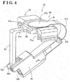
Fig. 4] Fig. 4 is a perspective view illustrating the seating detection apparatus illustrated inFig. 3 . - [
Fig. 5] Fig. 5 is a view used for explaining that load is transmitted in a cushion member when the load is applied. - [
Fig. 6] Fig. 6 is a perspective view illustrating a state in which a seating detection apparatus of a second embodiment of the present invention is attached to the seat for the vehicle. - [
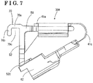
Fig. 7] Fig. 7 is a side view illustrating the seating detection apparatus illustrated inFig. 6 . - [
Fig. 8] Fig. 8 is a perspective view illustrating a state in which a seating detection apparatus of a third embodiment of the present invention is attached to the seat for the vehicle. - [
Fig. 9] Fig. 9 is a perspective view illustrating the seating detection apparatus illustrated inFig. 8 . - [
Fig. 10] Fig. 10 is a perspective view viewing, from an obliquely downward direction, the state illustrated inFig. 8 in which the seating detection apparatus is attached to the seat for the vehicle. - [
Fig. 11A] Fig. 11A is a cross-sectional view illustrating a seating detection apparatus of a fourth embodiment of the present invention. - [
Fig. 11B] Fig. 11B is a cross-sectional view illustrating a seating detection apparatus of another example of the fourth embodiment of the present invention. - A case will be described in which a seating detection apparatus of a first embodiment of the present invention is applied to a seat for a vehicle with reference to
Figs. 1 to 4 . Aseat 10 for a vehicle includes first and secondseat truck mechanism lower arms back frame 16, afront cushion frame 17, a support member 18, aconnection shaft 19 and acushion member 21. - The first
seat truck mechanism 11 is arranged at an outer side of the seat, and is formed by a firstlower rail 11a provided at a floor side and a firstupper rail 11b slidably engaging with the firstlower rail 11a. Similarly, the secondseat truck mechanism 12 is arranged at an inner side of the seat, and is formed by a secondlower rail 12a provided at the floor side and a secondupper rail 12b slidably engaging with the secondlower rail 12a. - The first and second
lower arms upper rails operation handle 15 of the lift mechanism is for transitioning a lock state in which the first and secondlower arms lower arms - The
back frame 16 is tiltably attached to rear portions of the first and secondlower arms back frame 16 is for transitioning a lock state in which theback frame 16 is prohibited from tilting to an unlock state in which theback frame 16 is allowed to tilt. - The
front cushion frame 17 which is pivoted about apin 17a by a front tilt mechanism is provided at front portions of the first and secondlower arms pin 17a in an upper and lower direction due to rotation of anoperation handle 17b of the front tilt mechanism which is provided via a braking mechanism. - The support member 18 supporting the
cushion member 21 from below is formed by a spring member (which will be hereinafter referred to as "S spring") 18 in which steel wire is bent continually in S shapes and which includes a spring function. The S spring 18 is hung between theconnection shaft 19 and thefront cushion frame 17, and is secured at theconnection shaft 19 and thefront cushion frame 17. Theconnection shaft 19 transmits a movement of the lift mechanism on a side of the firstseat truck mechanism 11 to the lift mechanism on a side of the secondseat truck mechanism 12. - As illustrated in
Figs. 1 and2 , below thecushion member 21, aseating detection apparatus 30 is attached to and supported by the S spring 18. A front surface of thecushion member 21 is covered with asurface cover 22 including leather, fiber and moquette, for example. - As illustrated in
Figs. 3 and4 , theseating detection apparatus 30 includes aload detection apparatus 40 and aholder 50. As illustrated mainly inFig. 4 , theload detection apparatus 40 includes amembrane switch 41 formed in a film shape or in a sheet shape, and aconnector 42. Themembrane switch 41 includes adetection portion 41a and anoutput portion 41b. As illustrated inFig. 2A , thedetection portion 41a is arranged below thecushion member 21 of thecushion portion 20 of theseat 10 for the vehicle and detects load information. - As illustrated in
Fig. 2B , thedetection portion 41a includes an upper portion film 41a1, a lower portion film 41a2 and a separation holding portion 41a3. An upper surface (an outer surface) of the upper portion film 41a1 is in contact with a bottom surface of thecushion member 21 and acontact point 41 a4 is provided at a center of an inner surface of the upper portion film 41a1. A bottom surface (an outer surface) of the lower portion film 41a2 is in contact with an upper surface of aspacer 60 and a contact point 41a5 is provided at a center of an inner surface of the lower portion film 41a2. The separation holding portion 41a3 is disposed between the upper portion film 41a1 and the lower portion film 41a2 along outer circumferential edges of the upper portion film 41a1 and the lower portion film 41a2. Hardness of the separation holding portion 41a3 is set at a value which is larger than hardness of thecushion member 21 and/or hardness of thespacer 60. These members are formed by an elastic material. The contact point 41a4 and the contact point 41a5 are arranged to face each other with a space portion provided therebetween. - When load is applied to the
cushion member 21 at thedetection portion 41 a including the above-described configuration, in a case where the hardness of thecushion member 21 and the hardness of thespacer 60 are equal to each other, the upper portion film 41a1 deflects downwardly due to the load from thecushion member 21, the lower portion film 41a2 deflects upwardly due to a reaction force from thespacer 60, and the contact point 41a4 and the contact point 41a5 are in contact with each other as illustrated inFig. 2C . Accordingly, thedetection portion 41 a is turned on and thus thedetection portion 41 a can detect the load information. At this time, amounts of deflection of the upper portion and the lower portion films 41a1 and 41a2 are equal to each other. In addition, because the load is concentrated at the upper portion film 41a1, sensitivity decreases. - In a case where the hardness of the
cushion member 21 is larger than the hardness of thespacer 60, the amount of deflection of the lower portion film 41a2 is larger than the amount of deflection of the upper portion film 41a1. In addition, in a case where the hardness of thecushion member 21 is smaller than the hardness of thespacer 60, the amount of deflection of thelower portion film 41 a2 is smaller than the amount of deflection of the upper portion film 41a1. - As described above, in the present embodiment, the load information is not an absolute load value. In a case where a load which is smaller than a predetermined load is applied, the load information of the present embodiment indicates such a state, that is, an off state. On the other hand, in a case where a load which is larger than the predetermined load is applied, the load information of the present embodiment indicates such a state, that is, an on state. It is ideal that one or
more detection portions 41a are formed. In the present embodiment, onedetection portion 41a is formed. - The
output portion 41b is connected to thedetection portion 41a via aconduction portion 41c formed by a flexible printed substrate including flexibility, for example. Theoutput portion 41b outputs the load information detected at thedetection portion 41a. That is, an output electrode is formed at theoutput portion 41b. Theconnector 42 is connected to theoutput portion 41b. In addition, theconnector 42 is configured to be attached to a holdingportion 52c provided at theholder 50, which will be described below, in a detachable manner. That is, theconnector 42 is provided with anengagement portion 42a for the holding portion, which disengageably engages with the holdingportion 52c. - As illustrated in
Fig. 4 , theholder 50 includes an extendedportion 52 formed to extend downwardly from a side opposite to a side at which theconduction portion 41c extends from thedetection portion 41 a. The holdingportion 52c is provided at a distal end side of the extendedportion 52, and the holdingportion 52c disengageably engages with theengagement portion 42a for the holding portion which is formed at theconnector 42. As illustrated inFig. 4 , theconduction portion 41c formed by the flexible printed substrate is bent so as to be folded back and theengagement portion 42a for the holding portion which is formed at theconnector 42 engages with and attached to the holdingportion 52c. Accordingly, theconnector 42 is arranged on a plane which is different from a plane on which thedetection portion 41 a is arranged in such a manner that theconnector 42 overlaps with thedetection portion 41a in a predetermined detection direction of the load information by thedetection portion 41 a. Aconnection port 42b for connecting to an external circuit is provided at a distal end of theconnector 42, and theconnector 42 is held at theholder 50 in such a manner that theconnection port 42b is open obliquely downwardly. - As illustrated in
Fig. 3 , theholder 50 allows theload detection apparatus 40 to be supported by the S spring 18 serving as the support member. Both ends of theholder 50 are attached to upper portions of two portions 18a1 and 18a2 of theS spring 18a in a manner that theholder 50 is across the portions 18a1 and 18a2. The two portions 18a1 and 18a2 oppose each other. The portion 18a1 corresponds to a front side portion and the portion 18a2 corresponds to a rear side portion. - A locking
portion 51a is formed at one end (a front end) of theholder 50. The lockingportion 51a engages with the front side portion 18a1 of theS spring 18a and is locked thereat in a disengageable manner. The lockingportion 51a includes a downward opening and an inner diameter of the opening is formed to be slightly smaller than theS spring 18a. Because the lockingportion 51a is fitted to an exterior of theS spring 18a, the lockingportion 51a is restricted from moving relative to theS spring 18a in a radial direction (a front and rear direction of the vehicle), however, the lockingportion 51 a can move relative to theS spring 18a in an axial direction of theS spring 18a (a right and left direction of the vehicle). - An
engagement portion 51b is formed at the other end (a rear end) of theholder 50. Theengagement portion 51b engages with the rear side portion 18a2 of theS spring 18a in a detachable manner. Theengagement portion 51b includes a cross section of a narrow elongated groove shape having an opening which opens towards the front side (which opens in the horizontal direction). An inner diameter of the opening is formed to be slightly larger than or approximately equal to theS spring 18a. Theengagement portion 51b can move relative to theS spring 18a in the radial direction (the front and rear direction of the vehicle) and theengagement portion 51b can move relative to theS spring 18a in the axial direction of theS spring 18a (the right and left direction of the vehicle). As illustrated inFig. 3 , the front side portion 18a1 of theS spring 18a and the rear side portion 18a2 of theS spring 18a are connected to each other at a connection portion 18a3 extended in a front and rear direction of the S spring 18. At a rear side relative to the rear side portion 18a2 of the S spring 18, a second rear side portion 18a4 extended in parallel with the rear side portion 18a2 is formed (refer toFigs. 6 and8 ), and the second rear side portion 18a4 is connected at a second connection portion 18a5 extended in parallel with the connection portion 18a3. The connection portion 18a3 and the second connection portion 18a5 are arranged to be apart from each other in the right and left direction, that is, a width direction of the vehicle. The lockingportion 51a and theengagement portion 51b are attachment portions being attachable to the S spring 18 (18a) serving as the support member supporting thecushion member 21 from below. - According to the
holder 50 configured as described above, when an occupant is seated, even in a case where theS spring 18a is extended and thus an interval between the front side portion 18a1 and the rear side portion 18a2 is expanded, the expansion is not prevented and theholder 50 is supported on theS spring 18a reliably. - In addition, a
pressure receiving portion 51c is formed at theholder 50. Thepressure receiving portion 51c is supported by the S spring 18 (18a1, 18a2) via the lockingportion 51a and theengagement portion 51b, and is arranged below thedetection portion 41 a of theload detection apparatus 40. Thepressure receiving portion 51c receives pressure from thecushion member 21 via at least thedetection portion 41 a. Thepressure receiving portion 51c is formed between the lockingportion 51a and theengagement portion 51b of theholder 50 to include a recessed configuration. - The
pressure receiving portion 51c is provided with thespacer 60. Thespacer 60 is attached to an upper surface of thepressure receiving portion 51c with adhesive agent or double-sided tape, for example. Thespacer 60 is configured to be disposed between thedetection portion 41a of theload detection apparatus 40 and thepressure receiving portion 51 c. Thespacer 60 is a thin plate-shaped member formed by an elastic material including cushion material, rubber material or cloth material (non-woven fabric, felt, for example). In the present embodiment, thespacer 60 is formed in a quadrate shape, is accommodated in a portion of the recessed configuration, and is broader than thedetection portion 41a. - The shape of the
spacer 60 may be changed by providing a protrusion or providing a recessed portion, or the material of thespacer 60 may be changed. Accordingly, the hardness of thespacer 60 is changed, and thus the sensitivity of thedetection portion 41a can be changed. The sensitivity of theprotection portion 41 a increases in a case where the protrusion is provided at thespacer 60. To the contrary, the sensitivity of theprotection portion 41a decreases in a case where the recessed portion is provided at thespacer 60. In a case of changing the sensitivity by changing the hardness, the sensitivity depends on a relative hardness difference between thecushion member 21 and thespacer 60. Specifically, there is a tendency that the larger the relative hardness difference is, the higher the sensitivity becomes, and that the smaller the relative hardness difference is, the lower the sensitivity becomes. More specifically, by setting the relative hardness difference of thecushion member 21 and thespacer 60, the load or the pressure is easily concentrated on a portion of the member of which the hardness is lower, the portion which corresponds to thedetection portion 41a. Accordingly, the amount of deflection at the portion becomes larger, and consequently the contact portion 41a4 and the contact portion 41a5 are easily in contact with each other. In consequence, the larger the relative hardness difference between thecushion member 21 and thespacer 60 is, the higher the sensitivity of thedetection portion 41 a is. However, even though the hardness difference is large, the sensitivity decreases in a case where the hardness of the spacer is significantly high and/or in a case where the hardness of the spacer is significantly low (for example, in a case where the hardness is not different from hardness of the holder 50 (in a case of being significantly high) and/or in a case where the recessed portion is provided in a region of thespacer 60, the region which corresponds to the film portion of thedetection portion 41 a (in a case of being significantly low), for example). - Next, the attachment of the
seating detection apparatus 30 to the S spring 18 serving as the support member will be described. First, theengagement portion 51b is made to engage with theS spring 18a (18a2). At this time, theengagement portion 51b engages with theS spring 18a, however, theholder 50 is rotatable about theS spring 18a serving as an axis. Theholder 50 is slidable within a rage in which theholder 50 does not disengage, while theS spring 18a serving as a guide pin. - Next, by rotating or sliding the
holder 50, theengagement portion 51a is made to engage with theS spring 18a (18a1) and to be locked thereat. - As described above, in a state where the
attachment portions 51a and 51bart attached to the support member 18 so that thedetection portion 41 a can detect the load information inputted from above via thecushion member 21, theconnector 42 is held by theholder 50 in such a manner that theconnection port 42b is open obliquely downwardly. - Transmission of the load at the
cushion member 21 will be described with reference toFig. 5 . In a case where an object A is placed on aseating surface 20a of thecushion portion 21 and thus the load is applied, the load spreads beyond a contact range S1 with which the object A is in contact and is transmitted within thecushion member 21 towards a substantially right downward direction (transmitted within a range drawn by the broken line inFig. 5 ). At this time, the load is transmitted to the bottom surface of thecushion member 21 in a range S2 that is broader than the contact range S1. In a case where thedetection portion 41 a of theload detection apparatus 40 is placed within the transmission range S2, the load can be detected. In the present embodiment, themembrane switch 41 is used as theload detection apparatus 40. In this case, only when load which is equal to or larger than the load by which themembrane switch 41 is turned on (the aforementioned predetermined load) is applied, the application of the load is detected. Thus, even in a case where thedetection portion 41 a is provided at the bottom surface of thecushion member 21, a state of the load when the load is applied to the seating surface can be detected reliably. - In addition, in a case where a local load is applied, the local load is transmitted only to a surface part and is not transmitted to the bottom surface of the
cushion member 21. Thus, it can be restricted that load applied by a corner portion of a baggage is detected erroneously. - In the above-described embodiments, the membrane switch is used as the
load detection apparatus 40, however, a stroke sensor may be used. A load detection apparatus may be used, which includes a detection portion using a piezoelectric element (a piezo element), and includes a detection circuit where a detection signal from the detection portion is processed and then is outputted as an output value. - In a case of the stroke sensor, a whole main body of the stroke sensor may be mounted on the
pressure receiving portion 51c and a connector of a wire harness connected to the main body may be fixed to the holdingportion 52c. In addition, also in a case of the load detection apparatus including the piezoelectric element, a whole main body with which the piezoelectric element and the detection circuit are integrated may be mounted on thepressure receiving portion 51 c, and a connector of a wire harness connected to the main body may be fixed to the holdingportion 52c. - Next, a
seating detection apparatus 30A of a second embodiment of the present invention will be described with reference toFigs. 6 and7 . Theseating detection apparatus 30A is formed by adding arestriction portion 70 to theholder 50 of theseating detection apparatus 30 of the first embodiment. Theseating detection apparatus 30A includes a configuration in which theholder 50 is attached to the rear side portion 18a2 of theS spring 18a and to the second rear side portion 18a4 of theS spring 18a, at the attachment portions (the lockingportion 51a and theengagement portion 51b). - The
restriction portion 70 restricts theholder 50 from displacing in an axial direction of the rear side portion 18a2 of theS spring 18a and of the second rear side portion 18a4 of theS spring 18a, and thus prevents theholder 50 from dislocating from a predetermined position. For example, therestriction portion 70 is formed integrally with the holdingportion 52c, and includes ahorizontal portion 70a and a downwardly extendedportion 70b. Thehorizontal portion 70a is extended in a direction of the second connection portion 18a5 of the S spring 18a1. The downwardlyextended portion 70b is extended downwardly from thehorizontal portion 70a. - The second connection portion 18a5 of the S spring 18a1 is accommodated in an
inner space portion 70c formed by thehorizontal portion 70a and the downwardly extendedportion 70b of therestriction portion 70. The downwardlyextended portion 70b of theholder 50 is in contact with the second connection portion 18a5 of the S spring 18a1, and accordingly theholder 50 is restricted from displacing in the axial direction of the rear side portion 18a2 and the second rear side portion 18a4 of theS spring 18a. In addition, thehorizontal portion 70a of therestriction portion 70 can support an excessive load and prevent the excessive load from being applied to thedetection portion 41a. - Next, a
seating detection apparatus 30B of a third embodiment of the present invention will be described with reference toFigs. 8 ,9 and 10 . Theseating detection apparatus 30B includes a configuration in which a second locking portion 51a1, which is similar to the lockingportion 51a, is provided at theholder 50 of theseating detection apparatus 30 of the first embodiment instead of theengagement portion 51b. As illustrated inFigs. 9 and 10 , the second locking portion 51a1 is arranged in a direction which is substantially perpendicular to the lockingportion 51 a. In addition, the configuration includes a second detection portion 41a1 in addition to thedetection portion 41 a, and thedetection portion 41a and the second detection portion 41a1 select an AND circuit or an OR circuit as needed. - At the
seating detection apparatus 30B, relative to theS spring 18a, theholder 50 is attached to the rear side portion 18a2 at the lockingportion 51a and theholder 50 is attached to the second connection portion 18a5 at thesecond locking portion 51a. Accordingly, theholder 50 is restricted from being displaced in the front and rear direction of the vehicle and in the width direction of the vehicle, and is prevented from dislocating from a predetermined attachment position. - Next, a
seating detection apparatus 30C of a fourth embodiment of the present invention will be described with reference toFigs. 11A and 11B . According to theseating detection apparatus 30C, at theholder 50 of theseating detection apparatus 30 of the first embodiment, a detectionsensitivity change portion 53 changing the detection sensitivity of thedetection portion 41a is formed above thedetection portion 41a to be integrally with theholder 50 or to be separately from theholder 50, so that the detectionsensitivity change portion 53 can press thedetection portion 41a. As illustrated inFig. 11A , the detectionsensitivity change portion 53 includes aprotrusion 53a formed at a side facing thedetection portion 41a and can change the detection sensitivity of thedetection portion 41 a. Alternatively, as illustrated inFig. 11B , the detectionsensitivity change portion 53 includes a recessed portion 53b formed at the side facing thedetection portion 41 a and can change the detection sensitivity of thedetection portion 41a. In a case where theprotrusion 53a is provided at the detectionsensitivity change portion 53, the sensitivity of thedetection portion 41a increases. To the contrary, in a case where the recessed portion 53b is provided at the detectionsensitivity change portion 53, the sensitivity of thedetection portion 41 a decreases. - In the above-described embodiments, the membrane switch is used as the
load detection apparatus 40, however, the stroke sensor may be used. The load detection apparatus may be used, which includes the detection portion using the piezoelectric element (the piezo element, for example), and includes the detection circuit where the detection signal from the detection portion is processed and then is outputted as an output value. - As described above, the
seating detection apparatus detection portion 41 a detecting the load information inputted from the predetermined detection direction, theconnector 42 including theconnection port 42b for connecting to the external circuit and arranged on the plane which is different from the plane on which thedetection portion 41a is arranged in such a manner that theconnector 42 overlaps with thedetection portion 41 a in the detection direction, theconduction portion 41c transmitting the load information from thedetection portion 41 a to theconnector 42 and arranged from thedetection portion 41a towards theconnector 42 in a state of being bent, and theholder 50 holding thedetection portion 41a and theconnector 42, and including theattachment portion 51a, 51a1, 51b which is attachable to the support member 18 supporting thecushion member 21 of theseat 10 for the vehicle from below. As thedetection portion 41a and theconnector 42 are arranged in the overlapped manner on the different planes from each other, a length in a lateral or the width direction is reduced, and an area of theholder 50 can be reduced. Accordingly, a restriction on the attachment position of theholder 50 to the support member 18 is reduced and a degree of freedom in attaching theholder 50 to the support member 18 can be enhanced. - As described above, according to the
seating detection apparatus attachment portion 51a, 51a1, 51b is attached to the support member 18 so that the load information inputted from above via thecushion member 21 is detectable by thedetection portion 41 a, theconnector 42 is held by theholder 50 in such a manner that theconnection port 42b is open towards the obliquely downward direction. Accordingly, the external circuit can be connected to theconnector 42 from the obliquely downward direction, and the connecting operation thereof is easier compared to a case where theconnector 42 is arranged horizontally. In addition, a bending stress of theconduction portion 41c can be reduced, thereby providing an advantage to strength. - As described above, according to the
seating detection apparatus holder 50 includes the holdingportion 52c being engageable with theconnector 42 and disengageable from theconnector 42. Accordingly, theconnector 42 can engage with theholder 50 and can be attached to theholder 50 reliably, thereby enhancing an assembling performance. - As described above, according to the
seating detection apparatus holder 50 includes the extendedportion 52 extended downwardly from the side opposite to the side on which theconduction portion 41c extends from thedetection portion 41a, and theextended portion 52 includes the holdingportion 52c at the distal end of the extendedportion 52. Accordingly, theconnector 42 can be held at a predetermined position. - As described above, according to the
seating detection apparatus attachment portion 51a, 51a1, 51b is provided at at least the two positions. Accordingly, theseating detection apparatus holder 50. - As described above, according to the
seating detection apparatus 30A of the third embodiment of the present invention, theattachment portions 51a and 51a1 are arranged in the directions which are substantially perpendicular to each other. Accordingly, the displacement of theholder 50 in the axial direction and the radial direction of the support member 18 is restricted, and theholder 50 can be held at the predetermined attachment position. - As described above, according to the
seating detection apparatus 30A of the second embodiment of the present invention, theholder 50 includes therestriction portion 70 restricting theholder 50 from displacing in the axial direction of the support member 18. Accordingly, it can be prevented that theholder 50 displaces in the axial direction of the support member 18 and thus is dislocated from the predetermined attachment position. - As described above, according to the
seating detection apparatus 30A of the second embodiment of the present invention, therestriction portion 70 includes thehorizontal portion 70a and the downwardly extendedportion 70b extended downwardly from thehorizontal portion 70a. Accordingly, the downwardly extendedportion 70b of theholder 50 and the support member 18 are in contact with each other to restrict theholder 50 from displacing in the axial direction of the support member 18. In addition, thehorizontal portion 70a can receive the load applied from above, and thus theholder 50 that is advantageous in the strength can be provided. - As described above, according to the
seating detection apparatus 30C of the fourth embodiment of the present invention, theholder 50 includes the detectionsensitivity change portion 53 which can change the detection sensitivity of thedetection portion 41a. As the detection sensitivity of thedetection portion 41 a is changeable, the seating detection apparatus can be communized and a mountability of the seating detection apparatus on the vehicle is enhanced. - As described above, according to the
seating detection apparatus 30C of the fourth embodiment of the present invention, the detectionsensitivity change portion 53 includes theprotrusion 53a or the recessed portion 53b. Theprotrusion 53a or the recessed portion 53b is provided at the portion facing thedetection portion 41 a. As the detectionsensitivity change portion 53 includes theprotrusion 53a or the recessed portion 53b which are formed at the portion facing thedetection portion 41a, the detectionsensitivity change portion 53 can change the detection sensitivity of thedetection portion 41a. In a case where theprotrusion 53a is provided at the detectionsensitivity change portion 53, the sensitivity of thedetection portion 41a increases. To the contrary, in a case where the recessed portion 53b is provided at the detectionsensitivity change portion 53, the sensitivity of thedetection portion 41a decreases. - As described above, according to the
seating detection apparatus detection portion 41a corresponds to themembrane switch 41 formed in the film-shape. Accordingly, thedetection portion 41a can be formed thin, and a drip proof performance and/or a dust proof performance can be enhanced. - In a case where plural embodiments exist, the characteristic part of each of the embodiments can be appropriately combined with each other unless otherwise stated.
-
- 10 ··········
- seat for vehicle
- 18 ························
- S spring (support member)
- 21 .......................
- cushion member
- 30, 30A, 30B, 30C ···
- seating detection apparatus
- 41 .......................
- membrane switch
- 41 a ························
- detection portion
- 41························
- conduction portion
- 42 .......................
- connector
- 42b ························
- connection port
- 50 .......................
- holder
- 51a ························
- locking portion (attachment portion)
- 51a1 ························
- second locking portion (attachment portion)
- 51b ························
- engagement portion (attachment portion)
- 52 .......................
- extended portion
- 53 ························
- detection sensitivity change portion
- 53a ························
- protrusion
- 53b ························
- recessed portion
- 70 .......................
- restriction portion
- 70a ························
- horizontal portion
- 70b ························
- downwardly extended portion
Claims (11)
- A seating detection apparatus comprising:a detection portion detecting load information inputted from a detection direction that is predetermined;a connector including a connection port for connecting to an external circuit and arranged on a plane which is different from a plane on which the detection portion is arranged in such a manner that the connector overlaps with the detection portion in the detection direction;a conduction portion transmitting the load information from the detection portion to the connector and arranged from the detection portion towards the connector in a state of being bent; anda holder holding the detection portion and the connector, and including an attachment portion which is attachable to a support member supporting a cushion member of a seat for a vehicle from below.
- The seating detection apparatus according to claim 1, wherein, in a state where the attachment portion is attached to the support member so that load information inputted from above via the cushion member is detectable by the detection portion, the connector is held by the holder in such a manner that the connection port is open obliquely downwardly.
- The seating detection apparatus according to either claim 1 or 2, wherein the holder includes a holding portion being engageable with the connector and disengageable from the connector.
- The seating detection apparatus according to claim 3, wherein
the holder includes an extended portion extended downwardly from a side opposite to a side on which the conduction portion extends from the detection portion, and
the extended portion includes the holding portion at a distal end of the extended portion. - The seating detection apparatus according to any one of claims 1 to 4, wherein the attachment portion is provided at at least two positions.
- The seating detection apparatus according to claim 5, wherein the attachment portions are arranged in directions which are substantially perpendicular to each other.
- The seating detection apparatus according to any one of claims 1 to 6, wherein the holder includes a restriction portion restricting the holder from displacing in an axial direction of the support member.
- The seating detection apparatus according to claim 7, wherein the restriction portion includes a horizontal portion and a downwardly extended portion extended downwardly from the horizontal portion.
- The seating detection apparatus according to any one of claims 1 to 8, wherein the holder includes a detection sensitivity change portion which is changeable detection sensitivity of the detection portion.
- The seating detection apparatus according to claim 9, wherein the detection sensitivity change portion includes a protrusion or a recessed portion, the protrusion or the recessed portion is provided at a portion facing the detection portion.
- The seating detection apparatus according to any one of claims 1 to 10, wherein the detection portion corresponds to a membrane switch formed in a film-shape.
Applications Claiming Priority (2)
| Application Number | Priority Date | Filing Date | Title |
|---|---|---|---|
| JP2013249833A JP6213195B2 (en) | 2013-12-03 | 2013-12-03 | Seating detection device |
| PCT/JP2014/066584 WO2015083390A1 (en) | 2013-12-03 | 2014-06-23 | Seat occupancy detection device |
Publications (3)
| Publication Number | Publication Date |
|---|---|
| EP3078540A1 true EP3078540A1 (en) | 2016-10-12 |
| EP3078540A4 EP3078540A4 (en) | 2016-12-14 |
| EP3078540B1 EP3078540B1 (en) | 2018-05-16 |
Family
ID=53273168
Family Applications (1)
| Application Number | Title | Priority Date | Filing Date |
|---|---|---|---|
| EP14867574.7A Not-in-force EP3078540B1 (en) | 2013-12-03 | 2014-06-23 | Seat detection apparatus |
Country Status (4)
| Country | Link |
|---|---|
| EP (1) | EP3078540B1 (en) |
| JP (1) | JP6213195B2 (en) |
| CN (1) | CN205800848U (en) |
| WO (1) | WO2015083390A1 (en) |
Cited By (1)
| Publication number | Priority date | Publication date | Assignee | Title |
|---|---|---|---|---|
| EP3381740A1 (en) * | 2017-03-28 | 2018-10-03 | Aisin Seiki Kabushiki Kaisha | Seating sensor |
Families Citing this family (2)
| Publication number | Priority date | Publication date | Assignee | Title |
|---|---|---|---|---|
| WO2018042685A1 (en) * | 2016-08-30 | 2018-03-08 | 株式会社フジクラ | Load detection sensor unit |
| JP6706590B2 (en) * | 2017-03-28 | 2020-06-10 | アイシン精機株式会社 | Seating sensor |
Family Cites Families (6)
| Publication number | Priority date | Publication date | Assignee | Title |
|---|---|---|---|---|
| JPS5443327Y2 (en) * | 1972-12-30 | 1979-12-14 | ||
| US6360618B2 (en) * | 1999-06-10 | 2002-03-26 | Delphi Technologies, Inc. | Weight sensing system |
| US6244116B1 (en) * | 1999-08-16 | 2001-06-12 | Cts Corporation | Automobile seat weight sensor |
| JP2005112335A (en) * | 2003-06-03 | 2005-04-28 | Bridgestone Corp | Seat with seating sensor and pad for seat |
| JP2005203282A (en) * | 2004-01-16 | 2005-07-28 | Aisin Seiki Co Ltd | Seating detection device |
| JP5549197B2 (en) * | 2009-11-20 | 2014-07-16 | アイシン精機株式会社 | Seating detection device |
-
2013
- 2013-12-03 JP JP2013249833A patent/JP6213195B2/en not_active Expired - Fee Related
-
2014
- 2014-06-23 EP EP14867574.7A patent/EP3078540B1/en not_active Not-in-force
- 2014-06-23 CN CN201490001200.2U patent/CN205800848U/en not_active Expired - Fee Related
- 2014-06-23 WO PCT/JP2014/066584 patent/WO2015083390A1/en not_active Ceased
Cited By (2)
| Publication number | Priority date | Publication date | Assignee | Title |
|---|---|---|---|---|
| EP3381740A1 (en) * | 2017-03-28 | 2018-10-03 | Aisin Seiki Kabushiki Kaisha | Seating sensor |
| CN108657027A (en) * | 2017-03-28 | 2018-10-16 | 爱信精机株式会社 | Seat occupancy sensor |
Also Published As
| Publication number | Publication date |
|---|---|
| EP3078540B1 (en) | 2018-05-16 |
| JP2015105086A (en) | 2015-06-08 |
| CN205800848U (en) | 2016-12-14 |
| EP3078540A4 (en) | 2016-12-14 |
| JP6213195B2 (en) | 2017-10-18 |
| WO2015083390A1 (en) | 2015-06-11 |
Similar Documents
| Publication | Publication Date | Title |
|---|---|---|
| JP2011105278A (en) | Seating detecting device | |
| JP6453093B2 (en) | Vehicle seat | |
| WO2015002076A1 (en) | Vehicle seat | |
| US8210607B2 (en) | Vehicle seat | |
| JP5549197B2 (en) | Seating detection device | |
| US20120126071A1 (en) | Center Armrest Supporting Structure | |
| EP3078540B1 (en) | Seat detection apparatus | |
| JP6583106B2 (en) | Vehicle seat | |
| US20100187874A1 (en) | Internal structure of seatback connected to active headrest | |
| JP2010139364A (en) | Load sensor for vehicle seat | |
| CN107406018A (en) | Vehicle Seats | |
| US20150239378A1 (en) | Head rest | |
| US9663009B2 (en) | Conveyance seat | |
| US20190061567A1 (en) | Vehicle seat | |
| US20170166087A1 (en) | Adjustment system for vehicle seat | |
| CN205010040U (en) | Seat occupies sensor unit and seat | |
| JP2001130369A (en) | Airbag system | |
| JP2016120798A (en) | Seating detection device | |
| EP4005867B1 (en) | Seat slide adjuster | |
| JP5007067B2 (en) | Vehicle seat | |
| JP4465985B2 (en) | Seat back bottom belt cover mounting structure | |
| JP2007118841A (en) | Vehicle seat headrest structure | |
| KR101720974B1 (en) | Seat frame comprising weight classification system for vehicle | |
| JP4303154B2 (en) | Occupant detection device | |
| US20240326671A1 (en) | Cable retaining apparatus and seat cable module |
Legal Events
| Date | Code | Title | Description |
|---|---|---|---|
| PUAI | Public reference made under article 153(3) epc to a published international application that has entered the european phase |
Free format text: ORIGINAL CODE: 0009012 |
|
| 17P | Request for examination filed |
Effective date: 20160601 |
|
| AK | Designated contracting states |
Kind code of ref document: A1 Designated state(s): AL AT BE BG CH CY CZ DE DK EE ES FI FR GB GR HR HU IE IS IT LI LT LU LV MC MK MT NL NO PL PT RO RS SE SI SK SM TR |
|
| AX | Request for extension of the european patent |
Extension state: BA ME |
|
| REG | Reference to a national code |
Ref country code: DE Ref legal event code: R079 Ref document number: 602014025723 Country of ref document: DE Free format text: PREVIOUS MAIN CLASS: B60N0002440000 Ipc: B60N0002000000 |
|
| A4 | Supplementary search report drawn up and despatched |
Effective date: 20161116 |
|
| RIC1 | Information provided on ipc code assigned before grant |
Ipc: A47C 7/62 20060101ALI20161110BHEP Ipc: B60N 2/70 20060101ALI20161110BHEP Ipc: B60N 2/00 20060101AFI20161110BHEP |
|
| DAX | Request for extension of the european patent (deleted) | ||
| GRAP | Despatch of communication of intention to grant a patent |
Free format text: ORIGINAL CODE: EPIDOSNIGR1 |
|
| INTG | Intention to grant announced |
Effective date: 20171124 |
|
| RAP1 | Party data changed (applicant data changed or rights of an application transferred) |
Owner name: AISIN SEIKI KABUSHIKI KAISHA |
|
| GRAS | Grant fee paid |
Free format text: ORIGINAL CODE: EPIDOSNIGR3 |
|
| GRAA | (expected) grant |
Free format text: ORIGINAL CODE: 0009210 |
|
| AK | Designated contracting states |
Kind code of ref document: B1 Designated state(s): AL AT BE BG CH CY CZ DE DK EE ES FI FR GB GR HR HU IE IS IT LI LT LU LV MC MK MT NL NO PL PT RO RS SE SI SK SM TR |
|
| REG | Reference to a national code |
Ref country code: GB Ref legal event code: FG4D |
|
| REG | Reference to a national code |
Ref country code: CH Ref legal event code: EP |
|
| REG | Reference to a national code |
Ref country code: IE Ref legal event code: FG4D |
|
| REG | Reference to a national code |
Ref country code: DE Ref legal event code: R096 Ref document number: 602014025723 Country of ref document: DE |
|
| REG | Reference to a national code |
Ref country code: AT Ref legal event code: REF Ref document number: 999231 Country of ref document: AT Kind code of ref document: T Effective date: 20180615 |
|
| REG | Reference to a national code |
Ref country code: FR Ref legal event code: PLFP Year of fee payment: 5 |
|
| REG | Reference to a national code |
Ref country code: NL Ref legal event code: MP Effective date: 20180516 |
|
| REG | Reference to a national code |
Ref country code: LT Ref legal event code: MG4D |
|
| PG25 | Lapsed in a contracting state [announced via postgrant information from national office to epo] |
Ref country code: LT Free format text: LAPSE BECAUSE OF FAILURE TO SUBMIT A TRANSLATION OF THE DESCRIPTION OR TO PAY THE FEE WITHIN THE PRESCRIBED TIME-LIMIT Effective date: 20180516 Ref country code: ES Free format text: LAPSE BECAUSE OF FAILURE TO SUBMIT A TRANSLATION OF THE DESCRIPTION OR TO PAY THE FEE WITHIN THE PRESCRIBED TIME-LIMIT Effective date: 20180516 Ref country code: BG Free format text: LAPSE BECAUSE OF FAILURE TO SUBMIT A TRANSLATION OF THE DESCRIPTION OR TO PAY THE FEE WITHIN THE PRESCRIBED TIME-LIMIT Effective date: 20180816 Ref country code: NO Free format text: LAPSE BECAUSE OF FAILURE TO SUBMIT A TRANSLATION OF THE DESCRIPTION OR TO PAY THE FEE WITHIN THE PRESCRIBED TIME-LIMIT Effective date: 20180816 Ref country code: FI Free format text: LAPSE BECAUSE OF FAILURE TO SUBMIT A TRANSLATION OF THE DESCRIPTION OR TO PAY THE FEE WITHIN THE PRESCRIBED TIME-LIMIT Effective date: 20180516 Ref country code: SE Free format text: LAPSE BECAUSE OF FAILURE TO SUBMIT A TRANSLATION OF THE DESCRIPTION OR TO PAY THE FEE WITHIN THE PRESCRIBED TIME-LIMIT Effective date: 20180516 |
|
| PG25 | Lapsed in a contracting state [announced via postgrant information from national office to epo] |
Ref country code: GR Free format text: LAPSE BECAUSE OF FAILURE TO SUBMIT A TRANSLATION OF THE DESCRIPTION OR TO PAY THE FEE WITHIN THE PRESCRIBED TIME-LIMIT Effective date: 20180817 Ref country code: LV Free format text: LAPSE BECAUSE OF FAILURE TO SUBMIT A TRANSLATION OF THE DESCRIPTION OR TO PAY THE FEE WITHIN THE PRESCRIBED TIME-LIMIT Effective date: 20180516 Ref country code: HR Free format text: LAPSE BECAUSE OF FAILURE TO SUBMIT A TRANSLATION OF THE DESCRIPTION OR TO PAY THE FEE WITHIN THE PRESCRIBED TIME-LIMIT Effective date: 20180516 Ref country code: RS Free format text: LAPSE BECAUSE OF FAILURE TO SUBMIT A TRANSLATION OF THE DESCRIPTION OR TO PAY THE FEE WITHIN THE PRESCRIBED TIME-LIMIT Effective date: 20180516 Ref country code: NL Free format text: LAPSE BECAUSE OF FAILURE TO SUBMIT A TRANSLATION OF THE DESCRIPTION OR TO PAY THE FEE WITHIN THE PRESCRIBED TIME-LIMIT Effective date: 20180516 |
|
| REG | Reference to a national code |
Ref country code: AT Ref legal event code: MK05 Ref document number: 999231 Country of ref document: AT Kind code of ref document: T Effective date: 20180516 |
|
| PG25 | Lapsed in a contracting state [announced via postgrant information from national office to epo] |
Ref country code: PL Free format text: LAPSE BECAUSE OF FAILURE TO SUBMIT A TRANSLATION OF THE DESCRIPTION OR TO PAY THE FEE WITHIN THE PRESCRIBED TIME-LIMIT Effective date: 20180516 Ref country code: SK Free format text: LAPSE BECAUSE OF FAILURE TO SUBMIT A TRANSLATION OF THE DESCRIPTION OR TO PAY THE FEE WITHIN THE PRESCRIBED TIME-LIMIT Effective date: 20180516 Ref country code: RO Free format text: LAPSE BECAUSE OF FAILURE TO SUBMIT A TRANSLATION OF THE DESCRIPTION OR TO PAY THE FEE WITHIN THE PRESCRIBED TIME-LIMIT Effective date: 20180516 Ref country code: CZ Free format text: LAPSE BECAUSE OF FAILURE TO SUBMIT A TRANSLATION OF THE DESCRIPTION OR TO PAY THE FEE WITHIN THE PRESCRIBED TIME-LIMIT Effective date: 20180516 Ref country code: DK Free format text: LAPSE BECAUSE OF FAILURE TO SUBMIT A TRANSLATION OF THE DESCRIPTION OR TO PAY THE FEE WITHIN THE PRESCRIBED TIME-LIMIT Effective date: 20180516 Ref country code: AT Free format text: LAPSE BECAUSE OF FAILURE TO SUBMIT A TRANSLATION OF THE DESCRIPTION OR TO PAY THE FEE WITHIN THE PRESCRIBED TIME-LIMIT Effective date: 20180516 Ref country code: EE Free format text: LAPSE BECAUSE OF FAILURE TO SUBMIT A TRANSLATION OF THE DESCRIPTION OR TO PAY THE FEE WITHIN THE PRESCRIBED TIME-LIMIT Effective date: 20180516 |
|
| REG | Reference to a national code |
Ref country code: CH Ref legal event code: PL |
|
| REG | Reference to a national code |
Ref country code: DE Ref legal event code: R097 Ref document number: 602014025723 Country of ref document: DE |
|
| PG25 | Lapsed in a contracting state [announced via postgrant information from national office to epo] |
Ref country code: SM Free format text: LAPSE BECAUSE OF FAILURE TO SUBMIT A TRANSLATION OF THE DESCRIPTION OR TO PAY THE FEE WITHIN THE PRESCRIBED TIME-LIMIT Effective date: 20180516 Ref country code: IT Free format text: LAPSE BECAUSE OF FAILURE TO SUBMIT A TRANSLATION OF THE DESCRIPTION OR TO PAY THE FEE WITHIN THE PRESCRIBED TIME-LIMIT Effective date: 20180516 |
|
| REG | Reference to a national code |
Ref country code: BE Ref legal event code: MM Effective date: 20180630 |
|
| REG | Reference to a national code |
Ref country code: IE Ref legal event code: MM4A |
|
| PLBE | No opposition filed within time limit |
Free format text: ORIGINAL CODE: 0009261 |
|
| STAA | Information on the status of an ep patent application or granted ep patent |
Free format text: STATUS: NO OPPOSITION FILED WITHIN TIME LIMIT |
|
| PG25 | Lapsed in a contracting state [announced via postgrant information from national office to epo] |
Ref country code: MC Free format text: LAPSE BECAUSE OF FAILURE TO SUBMIT A TRANSLATION OF THE DESCRIPTION OR TO PAY THE FEE WITHIN THE PRESCRIBED TIME-LIMIT Effective date: 20180516 Ref country code: LU Free format text: LAPSE BECAUSE OF NON-PAYMENT OF DUE FEES Effective date: 20180623 |
|
| 26N | No opposition filed |
Effective date: 20190219 |
|
| GBPC | Gb: european patent ceased through non-payment of renewal fee |
Effective date: 20180816 |
|
| PG25 | Lapsed in a contracting state [announced via postgrant information from national office to epo] |
Ref country code: LI Free format text: LAPSE BECAUSE OF NON-PAYMENT OF DUE FEES Effective date: 20180630 Ref country code: CH Free format text: LAPSE BECAUSE OF NON-PAYMENT OF DUE FEES Effective date: 20180630 Ref country code: IE Free format text: LAPSE BECAUSE OF NON-PAYMENT OF DUE FEES Effective date: 20180623 |
|
| PG25 | Lapsed in a contracting state [announced via postgrant information from national office to epo] |
Ref country code: BE Free format text: LAPSE BECAUSE OF NON-PAYMENT OF DUE FEES Effective date: 20180630 Ref country code: SI Free format text: LAPSE BECAUSE OF FAILURE TO SUBMIT A TRANSLATION OF THE DESCRIPTION OR TO PAY THE FEE WITHIN THE PRESCRIBED TIME-LIMIT Effective date: 20180516 |
|
| PG25 | Lapsed in a contracting state [announced via postgrant information from national office to epo] |
Ref country code: GB Free format text: LAPSE BECAUSE OF NON-PAYMENT OF DUE FEES Effective date: 20180816 |
|
| PG25 | Lapsed in a contracting state [announced via postgrant information from national office to epo] |
Ref country code: AL Free format text: LAPSE BECAUSE OF FAILURE TO SUBMIT A TRANSLATION OF THE DESCRIPTION OR TO PAY THE FEE WITHIN THE PRESCRIBED TIME-LIMIT Effective date: 20180516 |
|
| PG25 | Lapsed in a contracting state [announced via postgrant information from national office to epo] |
Ref country code: MT Free format text: LAPSE BECAUSE OF NON-PAYMENT OF DUE FEES Effective date: 20180623 |
|
| PG25 | Lapsed in a contracting state [announced via postgrant information from national office to epo] |
Ref country code: TR Free format text: LAPSE BECAUSE OF FAILURE TO SUBMIT A TRANSLATION OF THE DESCRIPTION OR TO PAY THE FEE WITHIN THE PRESCRIBED TIME-LIMIT Effective date: 20180516 |
|
| PG25 | Lapsed in a contracting state [announced via postgrant information from national office to epo] |
Ref country code: PT Free format text: LAPSE BECAUSE OF FAILURE TO SUBMIT A TRANSLATION OF THE DESCRIPTION OR TO PAY THE FEE WITHIN THE PRESCRIBED TIME-LIMIT Effective date: 20180516 |
|
| PG25 | Lapsed in a contracting state [announced via postgrant information from national office to epo] |
Ref country code: MK Free format text: LAPSE BECAUSE OF NON-PAYMENT OF DUE FEES Effective date: 20180516 Ref country code: HU Free format text: LAPSE BECAUSE OF FAILURE TO SUBMIT A TRANSLATION OF THE DESCRIPTION OR TO PAY THE FEE WITHIN THE PRESCRIBED TIME-LIMIT; INVALID AB INITIO Effective date: 20140623 Ref country code: CY Free format text: LAPSE BECAUSE OF FAILURE TO SUBMIT A TRANSLATION OF THE DESCRIPTION OR TO PAY THE FEE WITHIN THE PRESCRIBED TIME-LIMIT Effective date: 20180516 |
|
| PG25 | Lapsed in a contracting state [announced via postgrant information from national office to epo] |
Ref country code: IS Free format text: LAPSE BECAUSE OF FAILURE TO SUBMIT A TRANSLATION OF THE DESCRIPTION OR TO PAY THE FEE WITHIN THE PRESCRIBED TIME-LIMIT Effective date: 20180916 |
|
| PGFP | Annual fee paid to national office [announced via postgrant information from national office to epo] |
Ref country code: FR Payment date: 20200512 Year of fee payment: 7 Ref country code: DE Payment date: 20200609 Year of fee payment: 7 |
|
| REG | Reference to a national code |
Ref country code: DE Ref legal event code: R119 Ref document number: 602014025723 Country of ref document: DE |
|
| PG25 | Lapsed in a contracting state [announced via postgrant information from national office to epo] |
Ref country code: DE Free format text: LAPSE BECAUSE OF NON-PAYMENT OF DUE FEES Effective date: 20220101 |
|
| PG25 | Lapsed in a contracting state [announced via postgrant information from national office to epo] |
Ref country code: FR Free format text: LAPSE BECAUSE OF NON-PAYMENT OF DUE FEES Effective date: 20210630 |