EP3078479A1 - Ultrasonic welding device - Google Patents
Ultrasonic welding device Download PDFInfo
- Publication number
- EP3078479A1 EP3078479A1 EP14873454.4A EP14873454A EP3078479A1 EP 3078479 A1 EP3078479 A1 EP 3078479A1 EP 14873454 A EP14873454 A EP 14873454A EP 3078479 A1 EP3078479 A1 EP 3078479A1
- Authority
- EP
- European Patent Office
- Prior art keywords
- welding
- rotation axis
- support
- rotary
- sheet
- Prior art date
- Legal status (The legal status is an assumption and is not a legal conclusion. Google has not performed a legal analysis and makes no representation as to the accuracy of the status listed.)
- Granted
Links
Images






Classifications
-
- A—HUMAN NECESSITIES
- A61—MEDICAL OR VETERINARY SCIENCE; HYGIENE
- A61F—FILTERS IMPLANTABLE INTO BLOOD VESSELS; PROSTHESES; DEVICES PROVIDING PATENCY TO, OR PREVENTING COLLAPSING OF, TUBULAR STRUCTURES OF THE BODY, e.g. STENTS; ORTHOPAEDIC, NURSING OR CONTRACEPTIVE DEVICES; FOMENTATION; TREATMENT OR PROTECTION OF EYES OR EARS; BANDAGES, DRESSINGS OR ABSORBENT PADS; FIRST-AID KITS
- A61F13/00—Bandages or dressings; Absorbent pads
- A61F13/15—Absorbent pads, e.g. sanitary towels, swabs or tampons for external or internal application to the body; Supporting or fastening means therefor; Tampon applicators
- A61F13/15577—Apparatus or processes for manufacturing
- A61F13/15707—Mechanical treatment, e.g. notching, twisting, compressing, shaping
- A61F13/15739—Sealing, e.g. involving cutting
-
- A—HUMAN NECESSITIES
- A61—MEDICAL OR VETERINARY SCIENCE; HYGIENE
- A61F—FILTERS IMPLANTABLE INTO BLOOD VESSELS; PROSTHESES; DEVICES PROVIDING PATENCY TO, OR PREVENTING COLLAPSING OF, TUBULAR STRUCTURES OF THE BODY, e.g. STENTS; ORTHOPAEDIC, NURSING OR CONTRACEPTIVE DEVICES; FOMENTATION; TREATMENT OR PROTECTION OF EYES OR EARS; BANDAGES, DRESSINGS OR ABSORBENT PADS; FIRST-AID KITS
- A61F13/00—Bandages or dressings; Absorbent pads
- A61F13/15—Absorbent pads, e.g. sanitary towels, swabs or tampons for external or internal application to the body; Supporting or fastening means therefor; Tampon applicators
- A61F13/45—Absorbent pads, e.g. sanitary towels, swabs or tampons for external or internal application to the body; Supporting or fastening means therefor; Tampon applicators characterised by the shape
- A61F13/49—Absorbent pads, e.g. sanitary towels, swabs or tampons for external or internal application to the body; Supporting or fastening means therefor; Tampon applicators characterised by the shape specially adapted to be worn around the waist, e.g. diapers, nappies
- A61F13/496—Absorbent pads, e.g. sanitary towels, swabs or tampons for external or internal application to the body; Supporting or fastening means therefor; Tampon applicators characterised by the shape specially adapted to be worn around the waist, e.g. diapers, nappies in the form of pants or briefs
-
- B—PERFORMING OPERATIONS; TRANSPORTING
- B29—WORKING OF PLASTICS; WORKING OF SUBSTANCES IN A PLASTIC STATE IN GENERAL
- B29C—SHAPING OR JOINING OF PLASTICS; SHAPING OF MATERIAL IN A PLASTIC STATE, NOT OTHERWISE PROVIDED FOR; AFTER-TREATMENT OF THE SHAPED PRODUCTS, e.g. REPAIRING
- B29C65/00—Joining or sealing of preformed parts, e.g. welding of plastics materials; Apparatus therefor
- B29C65/02—Joining or sealing of preformed parts, e.g. welding of plastics materials; Apparatus therefor by heating, with or without pressure
- B29C65/08—Joining or sealing of preformed parts, e.g. welding of plastics materials; Apparatus therefor by heating, with or without pressure using ultrasonic vibrations
- B29C65/083—Joining or sealing of preformed parts, e.g. welding of plastics materials; Apparatus therefor by heating, with or without pressure using ultrasonic vibrations using a rotary sonotrode or a rotary anvil
- B29C65/086—Joining or sealing of preformed parts, e.g. welding of plastics materials; Apparatus therefor by heating, with or without pressure using ultrasonic vibrations using a rotary sonotrode or a rotary anvil using a rotary anvil
-
- B—PERFORMING OPERATIONS; TRANSPORTING
- B29—WORKING OF PLASTICS; WORKING OF SUBSTANCES IN A PLASTIC STATE IN GENERAL
- B29C—SHAPING OR JOINING OF PLASTICS; SHAPING OF MATERIAL IN A PLASTIC STATE, NOT OTHERWISE PROVIDED FOR; AFTER-TREATMENT OF THE SHAPED PRODUCTS, e.g. REPAIRING
- B29C65/00—Joining or sealing of preformed parts, e.g. welding of plastics materials; Apparatus therefor
- B29C65/02—Joining or sealing of preformed parts, e.g. welding of plastics materials; Apparatus therefor by heating, with or without pressure
- B29C65/08—Joining or sealing of preformed parts, e.g. welding of plastics materials; Apparatus therefor by heating, with or without pressure using ultrasonic vibrations
- B29C65/083—Joining or sealing of preformed parts, e.g. welding of plastics materials; Apparatus therefor by heating, with or without pressure using ultrasonic vibrations using a rotary sonotrode or a rotary anvil
- B29C65/087—Joining or sealing of preformed parts, e.g. welding of plastics materials; Apparatus therefor by heating, with or without pressure using ultrasonic vibrations using a rotary sonotrode or a rotary anvil using both a rotary sonotrode and a rotary anvil
-
- B—PERFORMING OPERATIONS; TRANSPORTING
- B29—WORKING OF PLASTICS; WORKING OF SUBSTANCES IN A PLASTIC STATE IN GENERAL
- B29C—SHAPING OR JOINING OF PLASTICS; SHAPING OF MATERIAL IN A PLASTIC STATE, NOT OTHERWISE PROVIDED FOR; AFTER-TREATMENT OF THE SHAPED PRODUCTS, e.g. REPAIRING
- B29C65/00—Joining or sealing of preformed parts, e.g. welding of plastics materials; Apparatus therefor
- B29C65/78—Means for handling the parts to be joined, e.g. for making containers or hollow articles, e.g. means for handling sheets, plates, web-like materials, tubular articles, hollow articles or elements to be joined therewith; Means for discharging the joined articles from the joining apparatus
- B29C65/7858—Means for handling the parts to be joined, e.g. for making containers or hollow articles, e.g. means for handling sheets, plates, web-like materials, tubular articles, hollow articles or elements to be joined therewith; Means for discharging the joined articles from the joining apparatus characterised by the feeding movement of the parts to be joined
- B29C65/7879—Means for handling the parts to be joined, e.g. for making containers or hollow articles, e.g. means for handling sheets, plates, web-like materials, tubular articles, hollow articles or elements to be joined therewith; Means for discharging the joined articles from the joining apparatus characterised by the feeding movement of the parts to be joined said parts to be joined moving in a closed path, e.g. a rectangular path
- B29C65/7882—Means for handling the parts to be joined, e.g. for making containers or hollow articles, e.g. means for handling sheets, plates, web-like materials, tubular articles, hollow articles or elements to be joined therewith; Means for discharging the joined articles from the joining apparatus characterised by the feeding movement of the parts to be joined said parts to be joined moving in a closed path, e.g. a rectangular path said parts to be joined moving in a circular path
- B29C65/7885—Rotary turret joining machines, i.e. having several joining tools moving around an axis
-
- B—PERFORMING OPERATIONS; TRANSPORTING
- B29—WORKING OF PLASTICS; WORKING OF SUBSTANCES IN A PLASTIC STATE IN GENERAL
- B29C—SHAPING OR JOINING OF PLASTICS; SHAPING OF MATERIAL IN A PLASTIC STATE, NOT OTHERWISE PROVIDED FOR; AFTER-TREATMENT OF THE SHAPED PRODUCTS, e.g. REPAIRING
- B29C65/00—Joining or sealing of preformed parts, e.g. welding of plastics materials; Apparatus therefor
- B29C65/78—Means for handling the parts to be joined, e.g. for making containers or hollow articles, e.g. means for handling sheets, plates, web-like materials, tubular articles, hollow articles or elements to be joined therewith; Means for discharging the joined articles from the joining apparatus
- B29C65/7858—Means for handling the parts to be joined, e.g. for making containers or hollow articles, e.g. means for handling sheets, plates, web-like materials, tubular articles, hollow articles or elements to be joined therewith; Means for discharging the joined articles from the joining apparatus characterised by the feeding movement of the parts to be joined
- B29C65/7888—Means for handling of moving sheets or webs
- B29C65/7894—Means for handling of moving sheets or webs of continuously moving sheets or webs
-
- B—PERFORMING OPERATIONS; TRANSPORTING
- B29—WORKING OF PLASTICS; WORKING OF SUBSTANCES IN A PLASTIC STATE IN GENERAL
- B29C—SHAPING OR JOINING OF PLASTICS; SHAPING OF MATERIAL IN A PLASTIC STATE, NOT OTHERWISE PROVIDED FOR; AFTER-TREATMENT OF THE SHAPED PRODUCTS, e.g. REPAIRING
- B29C66/00—General aspects of processes or apparatus for joining preformed parts
- B29C66/01—General aspects dealing with the joint area or with the area to be joined
- B29C66/03—After-treatments in the joint area
- B29C66/032—Mechanical after-treatments
- B29C66/0326—Cutting, e.g. by using waterjets, or perforating
-
- B—PERFORMING OPERATIONS; TRANSPORTING
- B29—WORKING OF PLASTICS; WORKING OF SUBSTANCES IN A PLASTIC STATE IN GENERAL
- B29C—SHAPING OR JOINING OF PLASTICS; SHAPING OF MATERIAL IN A PLASTIC STATE, NOT OTHERWISE PROVIDED FOR; AFTER-TREATMENT OF THE SHAPED PRODUCTS, e.g. REPAIRING
- B29C66/00—General aspects of processes or apparatus for joining preformed parts
- B29C66/01—General aspects dealing with the joint area or with the area to be joined
- B29C66/05—Particular design of joint configurations
- B29C66/10—Particular design of joint configurations particular design of the joint cross-sections
- B29C66/11—Joint cross-sections comprising a single joint-segment, i.e. one of the parts to be joined comprising a single joint-segment in the joint cross-section
- B29C66/112—Single lapped joints
- B29C66/1122—Single lap to lap joints, i.e. overlap joints
-
- B—PERFORMING OPERATIONS; TRANSPORTING
- B29—WORKING OF PLASTICS; WORKING OF SUBSTANCES IN A PLASTIC STATE IN GENERAL
- B29C—SHAPING OR JOINING OF PLASTICS; SHAPING OF MATERIAL IN A PLASTIC STATE, NOT OTHERWISE PROVIDED FOR; AFTER-TREATMENT OF THE SHAPED PRODUCTS, e.g. REPAIRING
- B29C66/00—General aspects of processes or apparatus for joining preformed parts
- B29C66/40—General aspects of joining substantially flat articles, e.g. plates, sheets or web-like materials; Making flat seams in tubular or hollow articles; Joining single elements to substantially flat surfaces
- B29C66/41—Joining substantially flat articles ; Making flat seams in tubular or hollow articles
- B29C66/43—Joining a relatively small portion of the surface of said articles
- B29C66/431—Joining the articles to themselves
-
- B—PERFORMING OPERATIONS; TRANSPORTING
- B29—WORKING OF PLASTICS; WORKING OF SUBSTANCES IN A PLASTIC STATE IN GENERAL
- B29C—SHAPING OR JOINING OF PLASTICS; SHAPING OF MATERIAL IN A PLASTIC STATE, NOT OTHERWISE PROVIDED FOR; AFTER-TREATMENT OF THE SHAPED PRODUCTS, e.g. REPAIRING
- B29C66/00—General aspects of processes or apparatus for joining preformed parts
- B29C66/80—General aspects of machine operations or constructions and parts thereof
- B29C66/81—General aspects of the pressing elements, i.e. the elements applying pressure on the parts to be joined in the area to be joined, e.g. the welding jaws or clamps
- B29C66/814—General aspects of the pressing elements, i.e. the elements applying pressure on the parts to be joined in the area to be joined, e.g. the welding jaws or clamps characterised by the design of the pressing elements, e.g. of the welding jaws or clamps
- B29C66/8145—General aspects of the pressing elements, i.e. the elements applying pressure on the parts to be joined in the area to be joined, e.g. the welding jaws or clamps characterised by the design of the pressing elements, e.g. of the welding jaws or clamps characterised by the constructional aspects of the pressing elements, e.g. of the welding jaws or clamps
- B29C66/81463—General aspects of the pressing elements, i.e. the elements applying pressure on the parts to be joined in the area to be joined, e.g. the welding jaws or clamps characterised by the design of the pressing elements, e.g. of the welding jaws or clamps characterised by the constructional aspects of the pressing elements, e.g. of the welding jaws or clamps comprising a plurality of single pressing elements, e.g. a plurality of sonotrodes, or comprising a plurality of single counter-pressing elements, e.g. a plurality of anvils, said plurality of said single elements being suitable for making a single joint
- B29C66/81465—General aspects of the pressing elements, i.e. the elements applying pressure on the parts to be joined in the area to be joined, e.g. the welding jaws or clamps characterised by the design of the pressing elements, e.g. of the welding jaws or clamps characterised by the constructional aspects of the pressing elements, e.g. of the welding jaws or clamps comprising a plurality of single pressing elements, e.g. a plurality of sonotrodes, or comprising a plurality of single counter-pressing elements, e.g. a plurality of anvils, said plurality of said single elements being suitable for making a single joint one placed behind the other in a single row in the feed direction
-
- B—PERFORMING OPERATIONS; TRANSPORTING
- B29—WORKING OF PLASTICS; WORKING OF SUBSTANCES IN A PLASTIC STATE IN GENERAL
- B29C—SHAPING OR JOINING OF PLASTICS; SHAPING OF MATERIAL IN A PLASTIC STATE, NOT OTHERWISE PROVIDED FOR; AFTER-TREATMENT OF THE SHAPED PRODUCTS, e.g. REPAIRING
- B29C66/00—General aspects of processes or apparatus for joining preformed parts
- B29C66/80—General aspects of machine operations or constructions and parts thereof
- B29C66/81—General aspects of the pressing elements, i.e. the elements applying pressure on the parts to be joined in the area to be joined, e.g. the welding jaws or clamps
- B29C66/816—General aspects of the pressing elements, i.e. the elements applying pressure on the parts to be joined in the area to be joined, e.g. the welding jaws or clamps characterised by the mounting of the pressing elements, e.g. of the welding jaws or clamps
- B29C66/8167—Quick change joining tools or surfaces
-
- B—PERFORMING OPERATIONS; TRANSPORTING
- B29—WORKING OF PLASTICS; WORKING OF SUBSTANCES IN A PLASTIC STATE IN GENERAL
- B29C—SHAPING OR JOINING OF PLASTICS; SHAPING OF MATERIAL IN A PLASTIC STATE, NOT OTHERWISE PROVIDED FOR; AFTER-TREATMENT OF THE SHAPED PRODUCTS, e.g. REPAIRING
- B29C66/00—General aspects of processes or apparatus for joining preformed parts
- B29C66/80—General aspects of machine operations or constructions and parts thereof
- B29C66/83—General aspects of machine operations or constructions and parts thereof characterised by the movement of the joining or pressing tools
- B29C66/834—General aspects of machine operations or constructions and parts thereof characterised by the movement of the joining or pressing tools moving with the parts to be joined
- B29C66/8351—Jaws mounted on rollers, cylinders, drums, bands, belts or chains; Flying jaws
- B29C66/83511—Jaws mounted on rollers, cylinders, drums, bands, belts or chains; Flying jaws jaws mounted on rollers, cylinders or drums
-
- B—PERFORMING OPERATIONS; TRANSPORTING
- B29—WORKING OF PLASTICS; WORKING OF SUBSTANCES IN A PLASTIC STATE IN GENERAL
- B29C—SHAPING OR JOINING OF PLASTICS; SHAPING OF MATERIAL IN A PLASTIC STATE, NOT OTHERWISE PROVIDED FOR; AFTER-TREATMENT OF THE SHAPED PRODUCTS, e.g. REPAIRING
- B29C66/00—General aspects of processes or apparatus for joining preformed parts
- B29C66/80—General aspects of machine operations or constructions and parts thereof
- B29C66/83—General aspects of machine operations or constructions and parts thereof characterised by the movement of the joining or pressing tools
- B29C66/836—Moving relative to and tangentially to the parts to be joined, e.g. transversely to the displacement of the parts to be joined, e.g. using a X-Y table
- B29C66/8362—Rollers, cylinders or drums moving relative to and tangentially to the parts to be joined
-
- B—PERFORMING OPERATIONS; TRANSPORTING
- B29—WORKING OF PLASTICS; WORKING OF SUBSTANCES IN A PLASTIC STATE IN GENERAL
- B29C—SHAPING OR JOINING OF PLASTICS; SHAPING OF MATERIAL IN A PLASTIC STATE, NOT OTHERWISE PROVIDED FOR; AFTER-TREATMENT OF THE SHAPED PRODUCTS, e.g. REPAIRING
- B29C66/00—General aspects of processes or apparatus for joining preformed parts
- B29C66/80—General aspects of machine operations or constructions and parts thereof
- B29C66/84—Specific machine types or machines suitable for specific applications
- B29C66/841—Machines or tools adaptable for making articles of different dimensions or shapes or for making joints of different dimensions
- B29C66/8412—Machines or tools adaptable for making articles of different dimensions or shapes or for making joints of different dimensions of different length, width or height
-
- A—HUMAN NECESSITIES
- A61—MEDICAL OR VETERINARY SCIENCE; HYGIENE
- A61F—FILTERS IMPLANTABLE INTO BLOOD VESSELS; PROSTHESES; DEVICES PROVIDING PATENCY TO, OR PREVENTING COLLAPSING OF, TUBULAR STRUCTURES OF THE BODY, e.g. STENTS; ORTHOPAEDIC, NURSING OR CONTRACEPTIVE DEVICES; FOMENTATION; TREATMENT OR PROTECTION OF EYES OR EARS; BANDAGES, DRESSINGS OR ABSORBENT PADS; FIRST-AID KITS
- A61F13/00—Bandages or dressings; Absorbent pads
- A61F13/15—Absorbent pads, e.g. sanitary towels, swabs or tampons for external or internal application to the body; Supporting or fastening means therefor; Tampon applicators
- A61F13/15577—Apparatus or processes for manufacturing
- A61F2013/15821—Apparatus or processes for manufacturing characterized by the apparatus for manufacturing
- A61F2013/15861—Apparatus or processes for manufacturing characterized by the apparatus for manufacturing for bonding
- A61F2013/15869—Apparatus or processes for manufacturing characterized by the apparatus for manufacturing for bonding with ultrasonic energy
-
- B—PERFORMING OPERATIONS; TRANSPORTING
- B29—WORKING OF PLASTICS; WORKING OF SUBSTANCES IN A PLASTIC STATE IN GENERAL
- B29C—SHAPING OR JOINING OF PLASTICS; SHAPING OF MATERIAL IN A PLASTIC STATE, NOT OTHERWISE PROVIDED FOR; AFTER-TREATMENT OF THE SHAPED PRODUCTS, e.g. REPAIRING
- B29C66/00—General aspects of processes or apparatus for joining preformed parts
- B29C66/80—General aspects of machine operations or constructions and parts thereof
- B29C66/82—Pressure application arrangements, e.g. transmission or actuating mechanisms for joining tools or clamps
- B29C66/822—Transmission mechanisms
- B29C66/8226—Cam mechanisms; Wedges; Eccentric mechanisms
- B29C66/82263—Follower pin or roller cooperating with a groove
-
- B—PERFORMING OPERATIONS; TRANSPORTING
- B29—WORKING OF PLASTICS; WORKING OF SUBSTANCES IN A PLASTIC STATE IN GENERAL
- B29C—SHAPING OR JOINING OF PLASTICS; SHAPING OF MATERIAL IN A PLASTIC STATE, NOT OTHERWISE PROVIDED FOR; AFTER-TREATMENT OF THE SHAPED PRODUCTS, e.g. REPAIRING
- B29C66/00—General aspects of processes or apparatus for joining preformed parts
- B29C66/90—Measuring or controlling the joining process
- B29C66/92—Measuring or controlling the joining process by measuring or controlling the pressure, the force, the mechanical power or the displacement of the joining tools
- B29C66/924—Measuring or controlling the joining process by measuring or controlling the pressure, the force, the mechanical power or the displacement of the joining tools by controlling or regulating the pressure, the force, the mechanical power or the displacement of the joining tools
- B29C66/9261—Measuring or controlling the joining process by measuring or controlling the pressure, the force, the mechanical power or the displacement of the joining tools by controlling or regulating the pressure, the force, the mechanical power or the displacement of the joining tools by controlling or regulating the displacement of the joining tools
- B29C66/92611—Measuring or controlling the joining process by measuring or controlling the pressure, the force, the mechanical power or the displacement of the joining tools by controlling or regulating the pressure, the force, the mechanical power or the displacement of the joining tools by controlling or regulating the displacement of the joining tools by controlling or regulating the gap between the joining tools
- B29C66/92613—Measuring or controlling the joining process by measuring or controlling the pressure, the force, the mechanical power or the displacement of the joining tools by controlling or regulating the pressure, the force, the mechanical power or the displacement of the joining tools by controlling or regulating the displacement of the joining tools by controlling or regulating the gap between the joining tools the gap being kept constant over time
-
- B—PERFORMING OPERATIONS; TRANSPORTING
- B29—WORKING OF PLASTICS; WORKING OF SUBSTANCES IN A PLASTIC STATE IN GENERAL
- B29L—INDEXING SCHEME ASSOCIATED WITH SUBCLASS B29C, RELATING TO PARTICULAR ARTICLES
- B29L2031/00—Other particular articles
- B29L2031/48—Wearing apparel
- B29L2031/4871—Underwear
- B29L2031/4878—Diapers, napkins
Definitions
- the present invention relates to an ultrasonic welding device for ultrasonically welding an object to be welded.
- Patent Literature 1 for ultrasonically welding an object to be welded (web) to form disposable diapers, for example.
- An ultrasonic welding device disclosed in Patent Literature 1 includes a drum having an outer surface configured to support an object to be welded that is continuously supplied, the drum being rotatable about a predetermined rotation axis, and a horn and an anvil attached to the drum to thereby revolve about the rotation axis and sandwich the object supported over the outer surface of the drum to ultrasonically weld the object.
- the first welding tool is attached to the drum in such a manner as to be movable relative to the second welding tool so that the first welding tool can move across the object supported over the outer surface of the drum.
- the drum rotates integrally with the horn and the anvil. Therefore, the rotation of the drum allows the object to be welded between the horn and the anvil while being conveyed.
- the period of conveying the object can also be used as a period of welding, unlike the case where an object to be welded is fed into the space between a horn and an anvil secured at a position. Therefore, it is possible to obtain a sufficient welding strength while conveying the object at a high speed.
- the drum is mounted with the anvil, the horn, and a structure for connecting these components to the drum. Therefore, there is a problem that the work of replacing the drum is very troublesome.
- Patent Literature 1 Japanese Patent Publication No. 3988835
- the present invention aims to provide an ultrasonic welding device allowing easy adjustment for changing the space between adjacent welding positions.
- the present invention provides an ultrasonic welding device for ultrasonically welding an object to be welded, comprising: a rotary support mechanical assembly rotatable about a predetermined rotation axis and operable to support the object over a circumference centered on the rotation axis, the object being continuously supplied; and at least a pair of a horn and an anvil attached to the rotary support mechanical assembly to thereby revolve about the rotation axis and sandwich the object supported over the rotary support mechanical assembly to weld the object, when one of the horn and the anvil is defined as a first welding tool and the other of the horn and the anvil is defined as a second welding tool, the first welding tool being attached to the rotary support mechanical assembly in such a manner as to be movable relative to the second welding tool between a position to sandwich the object in cooperation with the second welding tool and a position away from the second welding tool, wherein the rotary support mechanical assembly includes a rotary member rotatable about the rotation axis
- a disposable diaper 70 includes, when it is worn, a front abdominal section 20a disposed on the abdomen of a wearer, a rear dorsal section 70b disposed on the buttocks of the wearer, and a crotch section 70c which extends from the front abdominal section 70a, passing between the legs of the wearer, up to the rear dorsal section 70b.
- Opposite lateral edge portions of the front abdominal section 70a are welded to opposite lateral edge portions of the rear dorsal section 70b via two weld sections S in such a manner that the front abdominal section 70a and the rear dorsal section 70b are connected in a ring.
- a sheet W extending in a specific direction is conveyed in its longitudinal direction.
- the flow direction of the sheet W will be referred to as transverse direction
- the direction perpendicularly intersecting the transverse direction in FIG. 1 will be referred to as vertical direction.
- the sheet W includes an inner sheet which faces the body surface of the wearer when it is worn, an outer sheet which faces away from the wearer when it is worn, and an elastic member sandwiched between the inner sheet and the outer sheet.
- leg holes L are formed in a central portion of the sheet W in the vertical direction.
- a portion between each two leg holes L in the sheet W corresponds to the crotch section 70c. Further, in the sheet W, both sides of each portion corresponding to the crotch section 70c in the vertical direction respectively correspond to the front abdominal section 70a and the rear dorsal section 70b.
- absorbers A are bonded to the sheet W each at a position between two leg holes L.
- the absorber A includes a permeable sheet having liquid permeability, a water-repellent sheet having water-repellency and breathability, and an absorbent core sandwiched between the permeable sheet and the water-repellent sheet.
- absorbent cores may be sandwiched and bonded between the inner sheet and the outer sheet of the sheet W.
- the inner sheet includes a sheet having liquid permeability
- the outer sheet includes a sheet having water-repellency and breathability.
- a fold-in-half step P4 the sheet W having the absorbers A placed thereon is folded in half in the vertical direction. As a result, portions corresponding to the front abdominal section 70a and portions corresponding to the rear dorsal section 70b in the sheet W are placed on each other.
- a portion corresponding to a lateral edge portion of the front abdominal section 70a and a portion corresponding to a lateral edge portion of the rear dorsal section 70b are ultrasonically welded.
- the sheet W is ultrasonically welded over a range including a position at which cutting is performed in a cutting step P6 described below.
- Weld sections S are each formed over a welding range D1 extending in the vertical direction of the portion corresponding to the lateral edge portion of the front abdominal section 70a and the portion corresponding to the lateral edge portion of the rear dorsal section 70b.
- the sheet W is cut along a cutting line extending in the vertical direction at a central position of each weld section S formed in the welding step P5. As a result, the sheet W (continuous member) is cut into each disposable diaper 70.
- the ultrasonic welding device 1 is used for ultrasonically welding a sheet W that has folded in the fold-in-half step P4 and introduced via a feed-in roller F1, and feeding the welded sheet W to the cutting step P6 via a feed-out roller F2.
- the ultrasonic welding device 1 includes, as shown in FIGS. 2 and 3 , a drive shaft support member 2 standing on a predetermined work surface, a cam drum (driving mechanism) 3 secured to the drive shaft support member 2, cam followers (driving mechanism) 23 disposed in a cam groove 3a of the cam drum 3, a drive shaft 4 supported in a manner rotatable about a rotation axis L1 relative to the drive shaft support member 2, a rotary drum 5 secured to the drive shaft 4, ten welding units 6 secured to the rotary drum 5, ten power transmission mechanisms 7 (only two of which are shown in FIG.
- X direction the direction parallel to the rotation axis L1 in FIG. 3
- Z direction the vertical direction of FIG. 3
- Y direction the direction perpendicularly intersecting the X-Z plane
- the drive shaft support member 2 supports the above-described components (excluding the drive shaft support member 2) of the ultrasonic welding device 1 on the work surface.
- the drive shaft support member 2 is in the form of a plate having a through hole 2a passing therethrough in the X direction.
- the cam drum 3 is secured to the drive shaft support member 2 with one end in the X direction being fitted in the through hole 2a of the drive shaft support member 2. In this state, an axis of the cam drum 3 coincides with the rotation axis L1.
- the cam drum 3 has a circumferential surface formed with the cam groove 3a.
- the cam groove 3a has a shape that allows the cam followers 23 which revolve about the rotation axis L1 to move in the X direction, as described in detail later.
- the cam drum 3 and the cam followers 23 correspond to a driving mechanism which drives anvils 15 described later in such a manner that the anvils 15 move relative to horns 14.
- the drive shaft 4 is rotationally driven by the motor 10. Specifically, a belt V1 is wound around a pulley 4a provided at an intermediate portion of the drive shaft 4 and a pulley 10a provided at an output shaft of the motor 10. A power of the motor 10 is transmitted to the drive shaft 4 via the belt V1 according to rotation of the output shaft of the motor 10. The motor 10 is secured to the drive shaft support member 2 via an unillustrated bracket.
- the drive shaft 4 passes through the cam drum 3 in the X direction in a manner rotatable relative to the cam drum 3.
- the drive shaft 4 is indirectly supported on the drive shaft support member 2 via the cam drum 3.
- the base end of the drive shaft 4 lies on the side of the drive shaft support member 2 opposite to the cam drum 3, and the distal end of the drive shaft 4 lies on the side of the cam drum 3 opposite to the drive shaft support member 2.
- the rotary drum 5 includes a disk 5a secured to the distal end of the drive shaft 4, a covering wall 5b extending from the rim of the disk 5a in the X direction and covering the circumferential surface of the cam drum 3, and an adjuster plate 5c detachably attached to the side of the disk 5a opposite to the covering wall 5b.
- the disk 5a and the adjuster plate 5c correspond to a rotary member which is rotatable about the rotation axis L1.
- the adjuster plate 5c is formed with screw holes 5e (see FIG. 4 ) for attaching the welding units 6.
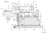
- the welding unit 6 includes a horn (second welding tool) 14 and an anvil (first welding tool) 15 for sandwiching the sheet W to thereby weld the sheet W, an ultrasonic wave generator 16 connected to the horn 14, a cooling jacket 17 (cooler) for cooling the ultrasonic wave generator 16, a attaching section 18 for allowing the welding unit 6 to be attached to the rotary drum 5 (adjuster plate 5c), a base 19 connected to an end of the attaching section 18 and extending in the X direction, a horn holding mechanism 20 provided at a distal end of the base 19 and holding the horn 14, and an anvil holding mechanism 21 provided at a base end of the base 19 and holding the anvil 15.
- the attaching sections 18 allow, as shown in FIGS. 2 and 3 , the welding units 6 to be attached to the rotary drum 5 in a state that the horn holding mechanisms 20 lie on the same circumference about the rotation axis L1. Further, the attaching sections 18 can be attached to the rotary drum 5 (adjuster plate 5c) in such a manner as to allow attaching positions of the welding units 6 to the rotary drum 5 to be adjusted in radial directions (in the Z direction in FIGS. 4 and 6 ) centered on the rotation axis L1.
- the attaching section 18 is formed with four long holes 18a extending in the radial direction (in the Z direction in FIG. 6 ) and passing therethrough in the X direction, as shown in FIG. 6 .
- the attaching section 18 can be attached to the adjuster plate 5c by inserting bolts B1 into the long holes 18a and screwing the bolts B1 into screw holes 5e of the adjuster plate 5c.
- a attaching position of the attaching section 18 (welding unit 6) can be adjusted in the radial direction by loosening the bolts B1 and moving the attaching section 18 in the radial direction and then screwing the bolts B1 into the screw holes 5e again.
- the adjustment range of the attaching position of the welding unit 6 can be expanded by attaching an alternative adjuster plate 5c to the disk 5a, the alternative adjuster plate 5c having screw holes 5e formed at different positions in the radial direction.
- the horn holding mechanism 20 supports the horn 14 with the horn 14 being exposed radially outward.
- the horn holding mechanism 20 includes a covering member 42 covering the horn 14 from one side (lower side in FIGS. 4 and 5 ) of the horn 14 in a radial direction and from both sides of the horn 14 in the Y direction, a horn support member 43 disposed inside the covering member 42 and supporting the horn 14, and a pair of sheet support members (object support members) 44 secured to the covering member 42.
- the covering member 42 includes a bottom plate 42a, and a pair of side plates 42b standing on opposite end portions of the bottom plate 42a in the Y direction.
- the bottom plate 42a is formed with a through-hole 42c passing therethrough in the Z direction.
- the ultrasonic wave generator 16 disposed radially inside the covering member 42 is connected to the horn 14 through the insertion hole 42c.
- the horn support member 43 is secured to the covering member 42 and supports an intermediate portion (a portion corresponding to a node of vibration transmitted from the ultrasonic wave generator 16) of the horn 14.
- a width dimension of the horn 14 in the X direction corresponds to a width (see FIG. 1 ) of the welding range D1 of the weld section S formed in the sheet W.
- each sheet support member 44 includes a support portion 44a extending in the circumferential direction from the horn 14, and a bending portion 44b extending at an angle from a circumferential end portion.
- the disk 5a and the adjuster plate 5c of the rotary drum 5, the attaching sections 18, and the sheet support members 44 correspond to a rotary support mechanical assembly which is rotatable about the rotation axis L1 and operable to support the sheet W over a circumference centered on the rotation axis L1, the sheet W being continuously supplied.
- the support portion 44a has a radially outer surface which serves as a support surface for supporting the sheet W. Specifically, a width dimension of the support portion 44a in the X direction corresponds to a width dimension D2 (see FIG. 1 ) between a waist side end portion and a crotch section side end portion of the sheet W.
- the bending portion 44b extends at an angle from a distal end of the support portion 44a and lies on the rotation axis L1 side of a straight line L2, the line L2 connecting distal end portions of adjacent support portions 44a, as shown in FIG. 5 .
- each portion of the sheet W (see FIG. 1 ) that includes the weld section S can be supported by the support portions 44a and the distal end of the horn 14, and each portion of the sheet W that includes the absorber A thicker than the weld section S can be disposed between adjacent bending portions 44b. Therefore, it is possible to prevent the portion of the sheet W exclusive of the absorbers A from rising due to the thickness of the absorbers A, unlike the case where the sheet W is supported on the same surface.
- the positions of the sheet support members 44 can be shifted by adjusting the above-mentioned attaching positions of the attaching sections 18 to the adjuster plate 5c. Specifically, for example, it is possible to increase the length (circumference) of the sheet W that can be supported by the sheet support members 44 by changing the attaching positions of the horn holding mechanisms 20 attached by means of the attaching sections 18 to radially outward positions centered on the rotation axis L1, as shown by the double dashed line in FIG. 8 .
- the attaching sections 18 and the adjuster plate 5c correspond to an attaching mechanism that allows the plurality of sheet support members 44 to be attached to the rotary drum 5 in a state that the sheet support members 44 lie on the same circumference about the rotation axis L1 and that allows the attaching positions of the sheet support members 44 to the rotary drum 5 to be adjusted in the radial directions centered on the rotation axis L1.
- the anvil holding mechanism 21 holds the anvil 15 in such a manner that the anvil 15 is movable relative to the horn holding mechanism 20 (the horn 14) in the X direction.
- the anvil holding mechanism 21 includes a pair of rail holding plates 45 standing on the base 19 and facing each other in the Y direction, a pair of rails 46 respectively held by the rail holding plates 45, a pair of sliders 47 respectively engageable with the rails 46 in a manner movable in the X direction, a main body 48 fixedly holding the sliders 47, three rotary shafts 49 to 51 provided in the main body 48, four timing pulleys 52 to 55 rotatable about the rotary shafts 49 to 51, respectively, timing belts V2 and V3 wound around the timing pulleys 52 to 55, and a connection member (see FIG. 4 ) 59 connecting the timing belt V2 and the rail holding plates 45.
- the main body 48 is attached to the rail holding plates 45 (the base 19) in a manner movable in the X direction owing to the engagement between the rails 46 and the sliders 47.
- the rotary shafts 49 to 51 each extend in the Y direction, the rotary shafts being arranged in the X direction and rotatable about an axis parallel to the Y direction relative to the main body 48.
- the timing pulley 52 is provided at one end of the rotary shaft 49.
- the timing pulley 53 is provided at one end portion of the rotary shaft 50 that is on the same side as the timing pulley 52, and the timing pulley 54 is provided at the other end portion of the rotary shaft 50 opposite to the timing pulley 53.
- the timing pulley 55 is provided at one end portion of the rotary shaft 51 that is on the same side as the timing pulley 54, and the anvil 15 is provided at the other end portion of the rotary shaft 51 opposite to the timing pulley 55.
- the timing belt V2 is wound around the timing pulley 52 and the timing pulley 53.
- the timing belt V3 is wound around the timing pulley 54 and the timing pulley 55.
- the connection member 59 connects a specific portion of the timing belt V2 and the rail holding plates 45, the specific portion of the timing belt V2 lying on a side of the rotation axis L1 side with respect to the timing pulleys 52 and 53.
- the power to move the timing belt V2 in the X direction is transmitted from the rail holding plates 45 through the connection member 59.
- the timing pulleys 52 and 53 rotate, and the rotation of the timing pulley 53 rotates the timing pulley 54. Consequently, the timing belt V3 moves to rotate the timing pulley 55, which in turn rotates the anvil 15.
- the anvil 15 rotates in response to moving in the X direction relative to the horn 14.
- the anvil 15 is reciprocatively moved relative to the horn 14, it is possible to bring the same position of an outer surface of the anvil 15 into contact with the same position of the sheet W in the forward stroke and the backward stroke of the reciprocation of the anvil 15. Therefore, in the case that a predetermined weld pattern is formed on the outer surface of the anvil 15, it is possible to reliably form a weld section corresponding to the weld pattern on the sheet W.
- the power transmission mechanisms 7 are attached to a circumferential surface of the covering wall 5b of the rotary drum 5.
- the covering wall 5b is formed with a long hole 5d for allowing the cam followers 23 to move along the cam groove 3a.
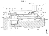
- the power transmission mechanism 7 includes, as shown in FIGS. 9 to 11 , a holding member 24 holding the cam follower 23, rails 25 supporting the hold member in such a manner that the holding member is movable in the X direction, a base 26 disposed on the rails 25, four brackets 27 standing on the base 26, a pair of timing pulleys 29 supported in a manner rotatable about support shafts 28 extending between the brackets 27, a timing belt (endless belt) 30 wound around the timing pulleys 29, and a connection mechanism 22 connected to the above-mentioned main body 48 of the anvil holding mechanism 21.
- the holding member 24 includes, as shown in FIG. 11 , a holding member body 24a secured to the cam follower 23, sliders 24b attached to opposite side surfaces of the holding member body 24a in the Y direction, and a clamping piece 24c for sandwiching the timing belt 30 in cooperation with the holding member body 24a.
- the weight of the cam follower 23 and the holding member 24 secured to the cam follower 23 is preferably equal to, but may be lighter than the weight of the main body 48 including the anvil 15. As described later, the cam follower 23 and the holding member 24 move in an opposite direction to the anvil 15 to thereby function as a weight which reduces vibration caused by the movement of the anvil 15.
- the sliders 24b are engaged with the rails 25 in a manner movable in the X direction.
- Bolts B3 are screwed into unillustrated screw holes formed in the holding member body 24a to thereby allow the clamping piece 24c to hold the timing belt 30 by sandwiching it in cooperation with the holding member body 24a.
- the base 26 includes a through hole 26a passing the base 26 in the Z direction, and the holding member 24 is inserted in the through hole 26a in a manner movable in the X direction.
- two of the brackets 27 are disposed on one side of the base 26 in the X direction and face each other in the Y direction, and the other two of the brackets 27 are disposed on the other side of the base 26 in the X direction and face in the Y direction.
- the support shafts 28 extending in the Y direction are each provided between two facing brackets 27, and the timing pulleys 29 are respectively provided at the support shafts 28.
- the above-mentioned holding member 24 is connected to a specific portion of the timing belt 30 that is on the side of the timing pulleys 29 closer to the rotation axis L1.
- the connection mechanism, 22 is connected to a specific portion of the timing belt 30 that is on the side of the timing pulleys 29 farther from the rotation axis L1.
- connection mechanism 22 includes a pair of a first clamping member 57 and a second clamping member 58 which sandwich the timing belt 30, and a connection plate 56 provided for connecting the first clamping member 57 and the above-mentioned main body 48 of the anvil holding mechanism 21.
- the first clamping member 57 includes an attached portion 57a for allowing the connection plate 56 to be attached thereto, the attached portion 57a having an insertion hole 57b passing therethrough in the Y direction.
- the above-mentioned main body 48 of the anvil holding mechanism 21 includes an attached portion 48a for allowing the connection plate 56 to be attached thereto, the attached portion 48a having an insertion hole 48b passing therethrough in the Y direction.
- connection plate 56 includes a pair of screw holes 56a for allowing bolts B2 that are respectively inserted in the insertion hole 57b of the first clamping member 57 and the insertion hole 48b of the main body 48 to be screwed therein. Therefore, it is possible to connect the timing belt 30 and the anvil holding mechanism 21 via the connection plate 56 by screwing the bolts B2 into the screw holes 56a.
- the attaching positions of the welding units 6 can be adjusted in radial directions centered on the rotation axis L1 by shifting the attaching positions of the attaching sections 18 along the long holes 18a (see FIGS. 6 and 8 ).
- the attaching positions of the welding units 6 are changed, the distance between the timing belt 30 and the anvil holding mechanisms 21 is changed in the radial directions. Therefore, by preparing an adjustment connection plate 56A that have screw holes 56a disposed at a different interval from the holes of the connection plate 56 in advance, it is possible to connect the timing belt 30 and the anvil holding mechanisms 21 even after the adjustment of the attaching positions of the welding units 6.
- the cam follower 23 and the anvil holding mechanism 21 are thus connected by the power transmission mechanism 7 to thereby allow the anvil 15 and the weight (the cam follower 23 and the holding member 24) to move as follows.
- the cam follower 23 and the holding member 24 supporting the cam follower 23 move in the X direction together.
- the connection mechanism 22 connected to the holding member 24 via the timing belt 30, i.e. the anvil holding mechanism 21 moves in the opposite direction to the cam follower 23 and the holding member 24 in the X direction.
- timing belt 30 and the timing pulleys 29 correspond to a power distribution mechanism.
- the range of movement of the anvil 15 is determined by the cam groove 3a, as follows.
- the anvil 15 is movable within a movable range between an initial position (the upper position shown in FIG. 3 ) shifted from the horn 14 on a side of the cam drum 3 in the X direction and a intermediate position (the lower position shown in FIG. 3 ) shifted from the horn 14 on an opposite side to the cam drum 3 in the X direction.
- the feed-in roller F1 and the feed-out roller F2 are disposed between a rotational position R1 and a rotational position R9 centered on the rotation axis L1.
- the angle between the rotational position R1 and the rotational position R9 is 36 degrees.
- the anvil 15 is disposed at the initial position (the upper position shown in FIG. 3 ) in an extent from the rotational position R9 to the rotational position R1.
- the anvil 15 accelerates from the initial position toward the intermediate position (hereinafter, the direction of this movement will be referred to as "forward").
- the angle between the rotational position R1 and the rotational position R2 is 36 degrees.
- the anvil 15 moves forward at a constant speed. During this movement, the sheet W is welded between the horn 14 and the anvil 15.
- the angle between the rotational position R2 and the rotational position R4 is 108 degrees.
- the anvil 15 decelerates (the anvil 15 is imparted with a backward acceleration) to stop at the intermediate position (the lower position shown in FIG. 3 ) when it reaches the rotational position R5.
- the angle between the rotational position R4 and the rotational position R5 is 18 degrees.
- the anvil 15 accelerates backward from the intermediate position toward the initial position.
- the angle between the rotational position R5 and the rotational position R6 is 18 degrees.
- the anvil 15 moves backward at a constant speed. During this movement, the sheet W is welded again between the horn 14 and the anvil 15.
- the angle between the rotational position R6 and the rotational position R8 is 108 degrees.
- the anvil 15 decelerates (the anvil 15 is imparted with a forward acceleration) to stop at the initial position when it reaches the rotational position R9.
- the angle between the rotational position R8 and the rotational position R9 is 36 degrees.
- two anvils 15 provided at symmetric positions by 180 degrees around the rotation axis L1 do not synchronously move in opposite directions especially during the acceleration and deceleration.
- the movement timings of the anvils 15 to the rotational positions are so set that two anvils 15 provided at symmetric positions by 180 degrees apart around the rotation axis L1 synchronously move in opposite directions, it is possible to reduce vibration of the ultrasonic welding device 1 as a whole, with or without the above-mentioned weights (the cam followers 23 and the holding members 24).
- the relationship between the rotational positions about the rotation axis L1 and the movement positions of the anvil 15 can be set by the cam groove 3a, as follows.
- the anvil 15 accelerates forward, and in an extent from the rotational position R2 to the rotational position R3, the anvil 15 is caused to move forward at a constant speed.
- the angle between the rotational position R2 and the rotational position R3 is 72 degrees.
- the anvil 15 decelerates to stop at the intermediate position when it reaches the rotational position R4.
- the angle between the rotational position R3 and the rotational position R4 is 36 degrees.
- the anvil 15 stops at the intermediate position. Consequently, one anvil 15 that rotates from the rotational position R9 to the rotational position R1 (to stop at the initial position) and another anvil 15 that rotates from the rotational position R4 to the rotational position R6 (to stop at the intermediate position) synchronously move in the opposite directions.
- the anvil 15 accelerates backward from the intermediate position.
- the angle between the rotational position R6 and the rotational position R7 is 36 degrees.
- the anvil 15 moves backward at a constant speed.
- the angle between the rotational position R7 and the rotational position R8 is 72 degrees.
- the anvil 15 decelerates to stop at the initial position when it reaches the rotational position R9.
- This configuration allows two anvils 15 provided at symmetric positions by 180 degrees apart around the rotation axis L1 to synchronously move in the opposite directions, which makes it possible to reduce vibration of the ultrasonic welding device 1 as a whole. Furthermore, the above-described configuration in which the weights (the cam followers 23 and the holding members 24) are caused to move in the opposite direction to the anvils 15 also makes it possible to reduce vibration in each welding unit 6. Therefore, the vibration of the ultrasonic welding device 1 as a whole can be more effectively reduced.
- two anvils 15 provided at symmetric positions by 180 degrees do not synchronize in the opposite directions, which, however, allows the anvils 15 to stop only for a short time. Owing to this, the period for welding the sheet W can be set long.
- the power transmission mechanism 7 is attached to the covering wall 5b of the rotary drum 5 in a state where the power transmission mechanism 7 covers the long hole 5d.
- the power transmission mechanism 7 includes a pair of ceiling plates 31 and a pair of side plates 32 disposed between the above-mentioned brackets 27, and a covering plate 33 disposed between the ceiling plates 31.
- the above-mentioned base 26 covers opposite end portions of the long hole 5d of the covering wall 5b in the X direction and exposes a middle portion of the long hole 5d through the through hole 26a.
- the ceiling plates 31, the side plates 32 and the covering plate 33 cover the portion of the long hole 5d that is exposed through the through hole 26a.
- the pair of side plates 32 stand respectively on opposite end portions of the base 26 in the X direction.
- Each side plate 32 is formed with a through hole 32a for allowing the timing belt 30 to pass therethrough.
- the ceiling plates 31 respectively extend from end portions of the side plates 32 in directions toward each other (in the X direction).
- the long hole 5d (the through hole 26a of the base 26) is thus covered, thereby making it possible to prevent entry of foreign matter into the long hole 5d.
- the base 26, the brackets 27, the ceiling plates 31, the side plates 32, and the covering plate 33 correspond to a holding mechanism that is attached to the covering wall 5b in a state where the holding mechanism covers the long hole 5d, the holding mechanism holding the timing belt 30 and the timing pulleys 29.
- the slip ring 8 allows electrical connection of an unillustrated power source to the ultrasonic wave generators 16 that revolve about the rotation axis L1, as shown in FIGS. 3 and 14 .
- the slip ring 8 includes a stationary terminal holding portion 34 secured to the drive shaft support member 2, and a rotary cylinder portion 35 rotatable about the rotation axis L1 relative to the stationary terminal holding portion 34.
- the stationary terminal holding portion 34 includes a plurality of stationary terminals 34a electrically connected to the unillustrated power source.
- the rotary cylinder portion 35 includes a plurality of rotary terminals 35a which remain electrically connected to the plurality of stationary terminals 34a even while rotating relative to the stationary terminal holding portion 34.
- the stationary terminals 34a are electrically connected to the rotary terminals 35a in one-to-one correspondence.
- the stationary terminal holding portion 34 includes conductive contact parts (unillustrated) electrically connected to the stationary terminals 34a
- the rotary cylinder portion 35 includes contact parts (unillustrated) electrically connected to the rotary terminals 35a.
- the rotary cylinder portion 35 is rotatable relative to the stationary terminal holding portion 34 with the respective contact parts being connected to each other.
- a wire C1 is connected to each rotary terminal 35a, the wires C1 being respectively connected to the ultrasonic wave generators 16.
- the plurality of stationary terminals 34a constitute a stationary connected portion and the plurality of rotary terminals 35a constitute a rotary connected portion.
- the rotary joint 9 allows connection of an unillustrated air source to the cooling jackets 17 that revolve about the rotation axis L1.
- the rotary joint 9 includes a stationary body 36 secured to the drive shaft support member 2 via a cover 60, and a rotary body 37 secured to the drive shaft 4 and rotatable about the rotation axis L1 relative to the stationary body 36.
- the stationary body 36 is secured to the stationary terminal holding portion 34 of the slip ring 8 via the cover 60.
- the stationary body 36 includes a stationary connection portion 36a connected to the unillustrated air source.
- the rotary body 37 is secured to the rotary cylinder portion 35 of the slip ring 8 via a support 61.
- the rotary body 37 includes a rotary connection portion 37a which remains connected to the stationary connection portion 36a even while rotating relative to the stationary body 36.
- the stationary body 36 includes a passage (unillustrated) connecting with the stationary connection portion 36a
- the rotary body 37 includes a passage (unillustrated) connecting with the rotary connection portion 37a.
- the rotary body 37 is rotatable relative to the stationary body 36 in the state that the respective passages communicate with each other.
- An air tube C2 is connected to the rotary connection portion 37a.
- the wires C1 and the air tube C2 run from the base end to the distal end of the drive shaft 4 through a through hole 4b which passes through the drive shaft 4 along the rotation axis L1.
- the distal end of the drive shaft 4 lies between a distal end E1 and a base end E2 of the rotary support mechanical assembly (the disk 5a, the adjuster plate 5c, the attaching sections 18, and the sheet support members 44).
- a wire guide member 11 and a tube connection member 12 are disposed at the distal end of the drive shaft 4.
- the wire guide member 11 guides the wires C1 drawn out from the distal end of the drive shaft 4 respectively to the ten ultrasonic wave generators 16, which are the destinations of the wires C1.
- the wire guide member 11 lies between the distal end E1 and the base end E2 of the rotary support mechanical assembly.
- the wire guide member 11 includes, as shown in FIG. 15 , a guide member body 38 in the form of a cylinder, and a stationary portion 39 projecting radially outward from a base end portion of the guide member body 38 and secured to the drive shaft 4 by bolts 4B.
- the guide member body 38 is formed with ten guide holes 38a disposed at positions corresponding to the ultrasonic wave generators 16 in a direction along the circumference about the rotation axis L1.
- the guide holes 38a are formed only over a region extending from a base end portion to an intermediate portion of the guide member body 38 along the rotation axis L1.
- the wires C1 are guided to the ultrasonic wave generators 16, i.e. the destinations of the wires C, through the guide holes 38a.
- the tube connection member 12 is connected to the air tube C2 drawn out from the distal end of the drive shaft 4, the tube connection member 12 being provided to guide air supplied from the air tube C2 into branched air tubes C3.
- the tube connection member 12 and the air tubes C2 and C3 correspond to an air circuit that connects the cooling jackets 17 and the rotary connection portion 37a of the rotary joint 9.
- the tube connection member 12 lies between the distal end portion E1 and the base end portion E2 of the rotary support mechanical assembly.
- the tube connection member 12 includes, as shown in FIG. 16 , a connection member body 40 engaged with the guide member body 38 from a distal end side of the guide member body 38, and ten connection cylinders 41 projecting from the connection member body 40 radially outward centered on the rotation axis L1.
- the tube connection member 12 includes a plurality of connection cylinders in addition to the ten connection cylinders 41, but the connection cylinders other than the ten connection cylinders 41 are not shown in FIG. 16 .
- connection member body 40 includes a communication passage 40a connecting with the air tube C2 introduced through the guide member body 38, and individual passages 40b extending from the communication passage 40a radially outward centered the rotation axis L1 and communicating with the connection cylinders 41.
- connection cylinders 41 are disposed at positions corresponding to the cooling jackets 17 in a direction along the circumference about the rotation axis L1.
- air introduced through the air tube C2 is distributed through the communication passage 40a, the individual passages 40b, and the connection cylinders 41 to be guided to the cooling jackets 17 through the air tubes C3 connected to the connection cylinders 41.
- Each cooling jacket 17 includes two tube connection portions, one of which is used to supply air and the other of which is used to discharge air.
- the connection portion for air discharge is exposed to the air directly or via an unillustrated silencer.
- the power transmission mechanism 7 distributes a power generated by the driving mechanism (the cam drum 3 and the cam follower 23) to the anvil 15 and the weight (the cam follower 23 and the holding member 24) in opposite directions. Therefore, it is possible to drive the holding member body 24a and the anvil 15 synchronously in the opposite directions.
- an acceleration change of the anvil 15 can be offset by a reverse acceleration change of the hold member body 24a when the anvil 15 is driven. Therefore, it is possible to reduce vibration that occurs in the ultrasonic welding device 1.
- the timing belt 30 is used to connect the cam follower 23 and the anvil holding mechanism 21. Therefore, the timing belt 30 can be used as a damper, owing to its flexibility, to absorb a shock generated when the anvil 15 is braked or activated. As a result, vibration caused by the shock can be reduced.
- the timing belt 30 is described as an example of the endless belt.
- any belt in the form of a loop may be used as the endless belt.
- the endless belt includes not only those belts that are made originally in the form of a loop, but also those belts that are made to have a loop form by connecting the opposite end portions of open belts by adhesion, welding or joint members.
- the holding mechanism (the base 26, the brackets 27, the ceiling plate 31, the side plates 32 and the covering plate 33) holding the timing belt 30 and the timing pulleys 29 can be used to cover the long hole 5d, which makes it possible to prevent entry of foreign matter into the cam groove 3a.
- long hole means a hole having a dimension in a moving direction (X direction) of the cam follower 23 longer than a dimension in a direction perpendicularly intersecting the moving direction.
- the long hole may have a plane shape having a truck-like or substantially rectangular shape.
- the cam drum 3 is so configured that two anvils 15 provided at symmetric positions by 180 degrees around the rotation axis L1 synchronously move in opposite directions, it is possible, between the two anvils 15 provided at symmetric positions by 180 degrees around the rotation axis L1, to allow respective accelerations of the anvils 15 to offset each other and respective accelerations of the holding member bodies 24a to offset each other.
- the sheet W can be supported on a circumference centered on the rotation axis L1 by the plurality of sheet support members 44 disposed on the same circumference about the rotation axis L1.
- the attaching mechanism (the adjuster plate 5c and the attaching sections 18) allows the attaching positions of the plurality of sheet support members 44 to be adjusted in the radial directions centered on the rotation axis L1. Therefore, it is possible to easily change the length of the circumference over which the sheet support members 44 are disposed.
- the sheet support members 44 are attached to the horn holding mechanisms 20, and the attaching sections 18 allow adjustment of the attaching positions of the horn holding mechanisms 20.
- the adjustment of the attaching positions of the horn holding mechanisms 20 also allows adjustment of the attaching positions of the sheet support members 44. This facilitates the adjustment of the space between adjacent welding positions.
- the horn holding mechanism 20 and the anvil holding mechanism 21 are connected via the base 19. Therefore, the attaching positions of the anvils 15, the horns 14, and the sheet support members 44 can be adjusted at once. This makes the adjustment of the space between adjacent welding positions extremely easy.
- the surfaces of the support portions 44a of the sheet support members 44 are respectively disposed on both sides of each horn 14 in the direction along the circumference about the rotation axis L1. This allows the sheet W, even in the case that the space between adjacent welding positions is increased (in the case that adjacent horns 14 are spaced apart a greater distance), to be supported on both sides of and near each of the horns 14. As a result, the sheet W is welded in a stable position, which improves the welding accuracy.
- the sheet support member 44 includes the support portion 44a and the bending portion 44b.
- a cavity is defined between each adjacent bending portions 44b of the sheet support members 44, the cavities recessed from the support portions 44a of the sheet support members 44. Therefore, thick portions (portions where the absorbers A are disposed: See FIG. 1 ) of the sheet W that each extend between adjacent welding target positions (weld sections S: See FIG. 1 ) can be placed in the cavities to thereby prevent the entire sheet W from rising from the sheet support members 44 due to the thick portions of the sheet W.
- the drive shaft 4 extends from a position on the base end side of the rotary support mechanical assembly (the disk 5a, the adjuster plate 5c, the attaching sections 18, and the sheet support members 44) to a position between the distal end E1 and the base end E2 of the rotary support mechanical assembly, unlike a conventional drive shaft provided at a position on the base end side of a drum.
- This makes it possible to rotatably support the rotary support mechanical assembly without the conventional stationary shaft provided for supporting the drum, by supporting an intermediate portion of the drive shaft 4 by the drive shaft support member 2.
- the distal end of the dive shaft 4 lies at a position on the base end side of a distal end surface of the rotary support member. This allows easy access to the rotary support mechanical assembly, the horns 14, and the anvils 15 from the distal end side of the rotary support mechanical assembly.
- a passage (the through hole 4b) defined in the drive shaft 4 is used as an arrangement route for the wires C1, the passage extending from the slip ring 8 disposed at the base end portion of the drive shaft 4 to the position between the distal end E1 and the base end E2 of the rotary support mechanical assembly as described.
- This allows at least a part of the wires C1 to be guided to the ultrasonic wave generators 16 through the inside of the rotary support mechanical assembly, unlike the conventional case where a wire is guided to a horn from the circumferential side of a drum.
- the slip ring 8 is described as an example of the rotary connector in which the electrical connection between the stationary terminals 34a and the rotary terminals 35a is maintained by the contact between the respective conductive contact parts.
- the rotary connector is not limited to the slip ring 8.
- a rotary connector may be used in which conductive liquid metal is provided between a stationary terminal holding portion 34 and a rotary cylinder portion 35.
- the ultrasonic wave generators 16 are disposed in the region on the rotation axis L1 side of the support portions 44a of the sheet support members 44 (inside the support portions 44a of the sheet support members 44). This allows the entire wires C1 to be placed in the region inside the rotary support mechanical assembly. Therefore, it is possible to prevent damage of the wires C1 more effectively.
- the sheet W can be held, not on a drum as in the conventional cases, but on the plurality of sheet support members 44 disposed over the same circumference centered on the rotation axis 11. Therefore, the space inside the sheet support members 44 can be used as a space for arranging the wires C1.
- the wire guide member 11 is provided to make it possible to guide the wires C1 drawn out from the distal end of the drive shaft 4 to the destinations of the wires C1.
- the plurality of wires C1 can be guided to the ultrasonic wave generators 16 in a neat way.
- the wire guide member 11 is disposed at the position between the distal end E1 and the base end E2 of the rotary support mechanical assembly (the disk 5a, the adjuster plate 5c, the attaching sections 18, and the sheet support members 44), it is possible to arrange the plurality of wires C1 without affecting the maintainability of the rotary support mechanical assembly, the horns 14, and the anvils 15.
- the air tube C2 can be guided from the base end portion to the distal end portion of the drive shaft 4 through the inside of the drive shaft 4 with the wires C1, the air tube C2 constituting a part of the air circuit connecting the cooling jackets 17 and the rotary joint 9.
- the above-described embodiment illustrates a case where the horn 14 is secured to the rotary drum 5 and the anvil 15 is movable relative to the horn 14.
- it may be configured such that the anvil 15 is secured to the rotary drum 5 and the horn 14 is movable relative to the anvil 15.
- the above-described embodiment illustrates a case where the timing belt 30 and the timing pulleys 29 are used as a structure for connecting the cam follower 23 and the anvil holding mechanism 21.
- the cam follower 23 and the anvil holding mechanism 21 may be connected via a link.
- the above-described embodiment illustrates a case where the sheet support members 44 are attached to the horn holding mechanisms 20.
- the sheet support members 44 may be attached directly to the rotary drum 5.
- support surfaces are respectively disposed on both sides of each horn 14 in the direction along the circumference about the rotation axis L1.
- a support surface may be disposed only on one side of each horn 14 in the circumferential direction.
- the above-described embodiment illustrates a case where a sheet support member 44 is disposed on each of both sides of the horn 14 in the circumferential direction.
- one sheet support member formed with a hole for exposing the horn 14 may be disposed to provide support surfaces on both sides of the horn 14 in the circumferential direction.
- the above-described embodiment illustrates a case where the ultrasonic wave generators 16 are disposed in the region on the rotation axis L1 side of the support portions 44a of the sheet support members 44 (inside the support portions 44a of the sheet support members 44).
- the ultrasonic wave generators 16 may be disposed outside the support portions 44a.
- the above-described embodiment illustrates a case where the cam follower 23 and the holding member 24 function as a weight.
- the weight may be provided independently of the holding member 24. Alternatively, it may be configured such that only the cam follower 23 functions as a weight.
- the above-described specific embodiment mainly includes the invention having the following configurations.
- the present invention provides an ultrasonic welding device for ultrasonically welding an object to be welded, comprising: a rotary support mechanical assembly rotatable about a predetermined rotation axis and operable to support the object over a circumference centered on the rotation axis, the object being continuously supplied; and at least a pair of a horn and an anvil attached to the rotary support mechanical assembly to thereby revolve about the rotation axis and sandwich the object supported over the rotary support mechanical assembly to weld the object, when one of the horn and the anvil is defined as a first welding tool and the other of the horn and the anvil is defined as a second welding tool, the first welding tool being attached to the rotary support mechanical assembly in such a manner as to be movable relative to the second welding tool between a position to sandwich the object in cooperation with the second welding tool and a position away from the second welding tool, wherein the rotary support mechanical assembly includes a rotary member rotatable about the rotation axis, a plurality of object support members each having
- the present invention it is possible to allow the plurality of object support members disposed on the same circumference about the rotation axis to support the object to be welded over the circumference centered on the rotation axis.
- the attaching mechanism allows the attaching positions of the plurality of object support members to be adjusted in the radial directions centered on the rotation axis. Therefore, it is possible to easily change the length of the circumference over which the object support members are disposed.
- welding an object to be welded includes welding of a plurality of objects to be welded that face each other, and welding of portions of an object to be welded that face each other as a result of folding up the object.
- the term "to be adjusted in radial directions" includes not only the case where adjustment can be made in directions parallel to radials through the rotation axis, but also the case where adjustment can be made in a direction along the circumference about the rotation axis in addition to the directions parallel to radials through the rotation axis.
- the term "to be adjusted in radial directions" means that the attaching positions of the object support members to the rotary member can be adjusted at least in the directions parallel to radials through the rotation axis.
- the plurality of object support members may be attached to the rotary support mechanical assembly, independently of the first welding tool and the second welding tool. However, in this case, it is necessary to adjust not only the attaching positions of the object support members, but also attaching positions of the first welding tool and the second welding tool.
- the rotary support mechanical assembly includes a plurality of second welding tool holding mechanisms for respectively holding the plurality of second welding tools, that the object support members are attached to the second welding tool holding mechanisms, and that the attaching mechanism allows the second welding tool holding mechanisms to be attached to the rotary member in a state that the second welding tool holding mechanisms lie on the same circumference about the rotation axis, and allows attaching positions of the second welding tool holding mechanisms to the rotary member to be adjusted in radial directions.
- the adjustment of the attaching positions of the second welding tool holding mechanisms also allows the adjustment of the attaching positions of the object support members. This therefore facilitates the adjustment of the space between adjacent welding positions.
- the rotary support mechanical assembly is preferred to further include a plurality of first welding tool holding mechanisms respectively attached to the second welding tool holding mechanisms for holding the plurality of first welding tools in such a manner that the first welding tools are movable relative to the second welding tools.
- the attaching positions of the first welding tools, the second welding tools, and the object support members can be adjusted at once. This makes the adjustment of the space between adjacent welding positions extremely easy.
- an object support member may be disposed only on one side of each second welding tool in a direction along the circumference about the rotation axis. In this case, however, a portion of the object lying on the other side of the second welding tool is supported by an object support member disposed on an adjacent second welding tool holding mechanism. However, in the case that the space between adjacent welding positions is increased, adjacent two second welding tool holding mechanisms are disposed at a distance from each other. Therefore, in this case, it is difficult to reliably support the object.
- the object support members are attached to the second welding tool holding mechanisms in such a manner that the support surfaces of the object support members respectively lie on both sides of each second welding tool in the direction along the circumference about the rotation axis.
- the object can be supported on both sides of and near each of the second welding tools. As a result, the object is welded in a stable position, which improves the welding accuracy.
- each of the plurality of object support members is preferred to include a support portion extending from the second welding tool in the circumferential direction and having the support surface, and a bending portion extending at an angle from a distal end of the support portion, the bending portion lying between a straight line connecting distal end portions of adjacent support portions of two second welding tools and the rotation axis.
- a cavity can be defined between each adjacent bending portions of the object support members, the cavities recessed form the support portions of the object support members. Therefore, in the case that the object includes thick portions that each extend between adjacent welding target positions set at intervals and that are thicker than the welding target positions, the thick portions of the object each extending between adjacent welding target positions can be placed in the cavities to thereby prevent the entire object from rising from the object support members due to the thick portions of the object.
Landscapes
- Engineering & Computer Science (AREA)
- Mechanical Engineering (AREA)
- Health & Medical Sciences (AREA)
- Animal Behavior & Ethology (AREA)
- Biomedical Technology (AREA)
- Heart & Thoracic Surgery (AREA)
- Vascular Medicine (AREA)
- Life Sciences & Earth Sciences (AREA)
- Epidemiology (AREA)
- General Health & Medical Sciences (AREA)
- Public Health (AREA)
- Veterinary Medicine (AREA)
- Manufacturing & Machinery (AREA)
- Lining Or Joining Of Plastics Or The Like (AREA)
- Absorbent Articles And Supports Therefor (AREA)
- Pressure Welding/Diffusion-Bonding (AREA)
Abstract
Description
- The present invention relates to an ultrasonic welding device for ultrasonically welding an object to be welded.
- Conventionally, there are known ultrasonic welding devices (for example, Patent Literature 1) for ultrasonically welding an object to be welded (web) to form disposable diapers, for example.
- An ultrasonic welding device disclosed in
Patent Literature 1 includes a drum having an outer surface configured to support an object to be welded that is continuously supplied, the drum being rotatable about a predetermined rotation axis, and a horn and an anvil attached to the drum to thereby revolve about the rotation axis and sandwich the object supported over the outer surface of the drum to ultrasonically weld the object. - When one of the horn and the anvil is defined as a first welding tool and the other of the horn and the anvil is defined as a second welding tool, the first welding tool is attached to the drum in such a manner as to be movable relative to the second welding tool so that the first welding tool can move across the object supported over the outer surface of the drum.
- According to the ultrasonic welding device disclosed in
Patent Literature 1, the drum rotates integrally with the horn and the anvil. Therefore, the rotation of the drum allows the object to be welded between the horn and the anvil while being conveyed. - Thus, the period of conveying the object can also be used as a period of welding, unlike the case where an object to be welded is fed into the space between a horn and an anvil secured at a position. Therefore, it is possible to obtain a sufficient welding strength while conveying the object at a high speed.
- By the way, it is necessary to change the space between adjacent welding positions of the object, according to the design of a product such as size that is made of the welded object.
- Here, in order to increase the space between adjacent welding positions, it is necessary to increase the circumference of the drum so that the circumference over which the object is welded by the welding tools is increased. On the other hand, in order to reduce the space between adjacent welding positions, it is necessary to reduce the circumference of the drum.
- However, in the ultrasonic welding device disclosed in
Patent Literature 1, the drum is used to support the object to be welded. Therefore, it is necessary to replace the drum to change the circumference of the drum. - Here, the drum is mounted with the anvil, the horn, and a structure for connecting these components to the drum. Therefore, there is a problem that the work of replacing the drum is very troublesome.
- Patent Literature 1: Japanese Patent Publication No.
3988835 - The present invention aims to provide an ultrasonic welding device allowing easy adjustment for changing the space between adjacent welding positions.
- In order to solve the above-mentioned problem, the present invention provides an ultrasonic welding device for ultrasonically welding an object to be welded, comprising: a rotary support mechanical assembly rotatable about a predetermined rotation axis and operable to support the object over a circumference centered on the rotation axis, the object being continuously supplied; and at least a pair of a horn and an anvil attached to the rotary support mechanical assembly to thereby revolve about the rotation axis and sandwich the object supported over the rotary support mechanical assembly to weld the object, when one of the horn and the anvil is defined as a first welding tool and the other of the horn and the anvil is defined as a second welding tool, the first welding tool being attached to the rotary support mechanical assembly in such a manner as to be movable relative to the second welding tool between a position to sandwich the object in cooperation with the second welding tool and a position away from the second welding tool, wherein the rotary support mechanical assembly includes a rotary member rotatable about the rotation axis, a plurality of object support members each having a support surface for supporting the object, and an attaching mechanism for allowing the plurality of object support members to be attached to the rotary member in a state that the object support members lie on the same circumference about the rotation axis, and allowing attaching positions of the object support members to the rotary member to be adjusted in radial directions centered on the rotation axis.
- According to the present invention, it is possible to allow easy adjustment for changing the space between adjacent welding positions.
-
-
FIG. 1 is a process diagram for explaining a method of producing disposable diapers with an ultrasonic welding device according to the present invention. -
FIG. 2 is a front view of an essential part of the ultrasonic welding device according to the present invention. -
FIG. 3 is a sectional view taken along the line III-III inFIG. 2 . -
FIG. 4 is an enlarged sectional view of a portion ofFIG. 3 . -
FIG. 5 is a front view showing a horn holding mechanism shown inFIG. 4 . -
FIG. 6 is a sectional view taken along the line VI-VI inFIG. 4 . -
FIG. 7 is a sectional view taken along the line VII-VII inFIG. 4 . -
FIG. 8 is a diagram corresponding toFIG. 2 ,FIG. 8 illustrating adjusted attaching positions of sheet support members. -
FIG. 9 is an enlarged sectional side view of a power transmission mechanism shown inFIG. 4 . -
FIG. 10 is a plan view of the power transmission mechanism shown inFIG. 9 . -
FIG. 11 is a sectional view taken along the line XI-XI inFIG. 9 . -
FIG. 12 is a sectional view taken along the line XII-XII inFIG. 9 . -
FIG. 13 is an enlarged sectional side view of a distal end configuration shown inFIG. 3 . -
FIG. 14 is an enlarged sectional side view of a base end configuration shown inFIG. 3 . -
FIG. 15 is a front view of a wire guide member shown inFIG. 13 , one-half being shown in section. -
FIG. 16 is a front view of a tube connecting member shown inFIG. 13 . - Hereinafter, an embodiment of the present invention will be described with reference to the accompanying drawings. It should be noted that the following embodiment illustrates an example of the invention, which therefore does not limit the protection scope of the invention.
- With reference to
FIG. 1 , adisposable diaper 70 includes, when it is worn, a front abdominal section 20a disposed on the abdomen of a wearer, a reardorsal section 70b disposed on the buttocks of the wearer, and acrotch section 70c which extends from the frontabdominal section 70a, passing between the legs of the wearer, up to the reardorsal section 70b. - Opposite lateral edge portions of the front
abdominal section 70a are welded to opposite lateral edge portions of the reardorsal section 70b via two weld sections S in such a manner that the frontabdominal section 70a and the reardorsal section 70b are connected in a ring. - In the following, a method of producing
disposable diapers 70 will be described. - In a conveyance step P1, a sheet W extending in a specific direction is conveyed in its longitudinal direction. In the description hereafter, the flow direction of the sheet W will be referred to as transverse direction, and the direction perpendicularly intersecting the transverse direction in
FIG. 1 will be referred to as vertical direction. - The sheet W includes an inner sheet which faces the body surface of the wearer when it is worn, an outer sheet which faces away from the wearer when it is worn, and an elastic member sandwiched between the inner sheet and the outer sheet.
- In a leg hole formation step P2, leg holes L are formed in a central portion of the sheet W in the vertical direction.
- A portion between each two leg holes L in the sheet W corresponds to the
crotch section 70c. Further, in the sheet W, both sides of each portion corresponding to thecrotch section 70c in the vertical direction respectively correspond to the frontabdominal section 70a and the reardorsal section 70b. - In an absorber bonding step P3, absorbers A are bonded to the sheet W each at a position between two leg holes L.
- The absorber A includes a permeable sheet having liquid permeability, a water-repellent sheet having water-repellency and breathability, and an absorbent core sandwiched between the permeable sheet and the water-repellent sheet.
- A method has been described in which the absorbers A are bonded onto the sheet W. Alternatively, absorbent cores may be sandwiched and bonded between the inner sheet and the outer sheet of the sheet W. In this case, the inner sheet includes a sheet having liquid permeability, and the outer sheet includes a sheet having water-repellency and breathability.
- In a fold-in-half step P4, the sheet W having the absorbers A placed thereon is folded in half in the vertical direction. As a result, portions corresponding to the front
abdominal section 70a and portions corresponding to the reardorsal section 70b in the sheet W are placed on each other. - In a welding step P5, between adjacent absorbers A in the sheet W folded in half (object to be welded), a portion corresponding to a lateral edge portion of the front
abdominal section 70a and a portion corresponding to a lateral edge portion of the reardorsal section 70b are ultrasonically welded. - Specifically, in the welding step P5, the sheet W is ultrasonically welded over a range including a position at which cutting is performed in a cutting step P6 described below.
- Weld sections S are each formed over a welding range D1 extending in the vertical direction of the portion corresponding to the lateral edge portion of the front
abdominal section 70a and the portion corresponding to the lateral edge portion of the reardorsal section 70b. - In the cutting step P6, the sheet W is cut along a cutting line extending in the vertical direction at a central position of each weld section S formed in the welding step P5. As a result, the sheet W (continuous member) is cut into each
disposable diaper 70. - In the following, an
ultrasonic welding device 1 that performs the welding step P5 will be described with reference toFIG. 2 . - The
ultrasonic welding device 1 is used for ultrasonically welding a sheet W that has folded in the fold-in-half step P4 and introduced via a feed-in roller F1, and feeding the welded sheet W to the cutting step P6 via a feed-out roller F2. - Specifically, the
ultrasonic welding device 1 includes, as shown inFIGS. 2 and3 , a driveshaft support member 2 standing on a predetermined work surface, a cam drum (driving mechanism) 3 secured to the driveshaft support member 2, cam followers (driving mechanism) 23 disposed in acam groove 3a of thecam drum 3, adrive shaft 4 supported in a manner rotatable about a rotation axis L1 relative to the driveshaft support member 2, arotary drum 5 secured to thedrive shaft 4, tenwelding units 6 secured to therotary drum 5, ten power transmission mechanisms 7 (only two of which are shown inFIG. 3 ) each provided for transmitting a power from thecam drum 3 and acam follower 23 to awelding unit 6, a slip ring (rotary connector) 8 and a rotary joint 9 provided at a base end of thedrive shaft 4, awire guide member 11 and atube connecting member 12 provided at a distal end of thedrive shaft 4, and amotor 10 for rotationally driving thedrive shaft 4. - In the description hereinafter, the direction parallel to the rotation axis L1 in
FIG. 3 will be referred to as "X direction", the vertical direction ofFIG. 3 will be referred to as Z direction, and the direction perpendicularly intersecting the X-Z plane will be referred to as "Y direction". - With reference to
FIGS. 3 and4 , the driveshaft support member 2 supports the above-described components (excluding the drive shaft support member 2) of theultrasonic welding device 1 on the work surface. Specifically, the driveshaft support member 2 is in the form of a plate having a throughhole 2a passing therethrough in the X direction. - The
cam drum 3 is secured to the driveshaft support member 2 with one end in the X direction being fitted in the throughhole 2a of the driveshaft support member 2. In this state, an axis of thecam drum 3 coincides with the rotation axis L1. - Further, the
cam drum 3 has a circumferential surface formed with thecam groove 3a. Thecam groove 3a has a shape that allows thecam followers 23 which revolve about the rotation axis L1 to move in the X direction, as described in detail later. Thecam drum 3 and thecam followers 23 correspond to a driving mechanism which drivesanvils 15 described later in such a manner that theanvils 15 move relative tohorns 14. - The
drive shaft 4 is rotationally driven by themotor 10. Specifically, a belt V1 is wound around apulley 4a provided at an intermediate portion of thedrive shaft 4 and apulley 10a provided at an output shaft of themotor 10. A power of themotor 10 is transmitted to thedrive shaft 4 via the belt V1 according to rotation of the output shaft of themotor 10. Themotor 10 is secured to the driveshaft support member 2 via an unillustrated bracket. - The
drive shaft 4 passes through thecam drum 3 in the X direction in a manner rotatable relative to thecam drum 3. In other words, thedrive shaft 4 is indirectly supported on the driveshaft support member 2 via thecam drum 3. The base end of thedrive shaft 4 lies on the side of the driveshaft support member 2 opposite to thecam drum 3, and the distal end of thedrive shaft 4 lies on the side of thecam drum 3 opposite to the driveshaft support member 2. - The
rotary drum 5 includes adisk 5a secured to the distal end of thedrive shaft 4, a coveringwall 5b extending from the rim of thedisk 5a in the X direction and covering the circumferential surface of thecam drum 3, and anadjuster plate 5c detachably attached to the side of thedisk 5a opposite to thecovering wall 5b. Thedisk 5a and theadjuster plate 5c correspond to a rotary member which is rotatable about the rotation axis L1. - The
adjuster plate 5c is formed withscrew holes 5e (seeFIG. 4 ) for attaching thewelding units 6. - Hereinafter, with reference to
FIGS. 4 to 7 , thewelding units 6 will be described. Because the tenwelding units 6 have the same configuration, description will be made about the configuration of onewelding unit 6 shown inFIGS. 4 to 7 . - The
welding unit 6 includes a horn (second welding tool) 14 and an anvil (first welding tool) 15 for sandwiching the sheet W to thereby weld the sheet W, anultrasonic wave generator 16 connected to thehorn 14, a cooling jacket 17 (cooler) for cooling theultrasonic wave generator 16, a attachingsection 18 for allowing thewelding unit 6 to be attached to the rotary drum 5 (adjuster plate 5c), a base 19 connected to an end of the attachingsection 18 and extending in the X direction, ahorn holding mechanism 20 provided at a distal end of thebase 19 and holding thehorn 14, and ananvil holding mechanism 21 provided at a base end of thebase 19 and holding theanvil 15. - The attaching
sections 18 allow, as shown inFIGS. 2 and3 , thewelding units 6 to be attached to therotary drum 5 in a state that thehorn holding mechanisms 20 lie on the same circumference about the rotation axis L1. Further, the attachingsections 18 can be attached to the rotary drum 5 (adjuster plate 5c) in such a manner as to allow attaching positions of thewelding units 6 to therotary drum 5 to be adjusted in radial directions (in the Z direction inFIGS. 4 and6 ) centered on the rotation axis L1. - Specifically, the attaching
section 18 is formed with fourlong holes 18a extending in the radial direction (in the Z direction inFIG. 6 ) and passing therethrough in the X direction, as shown inFIG. 6 . The attachingsection 18 can be attached to theadjuster plate 5c by inserting bolts B1 into thelong holes 18a and screwing the bolts B1 intoscrew holes 5e of theadjuster plate 5c. Further, a attaching position of the attaching section 18 (welding unit 6) can be adjusted in the radial direction by loosening the bolts B1 and moving the attachingsection 18 in the radial direction and then screwing the bolts B1 into thescrew holes 5e again. - In the case that the attaching position of the attaching
section 18 needs to be adjusted beyond the range of thelong hole 18a, the adjustment range of the attaching position of thewelding unit 6 can be expanded by attaching analternative adjuster plate 5c to thedisk 5a, thealternative adjuster plate 5c havingscrew holes 5e formed at different positions in the radial direction. - With reference to
FIGS. 4 and5 , thehorn holding mechanism 20 supports thehorn 14 with thehorn 14 being exposed radially outward. - Specifically, the
horn holding mechanism 20 includes a coveringmember 42 covering thehorn 14 from one side (lower side inFIGS. 4 and5 ) of thehorn 14 in a radial direction and from both sides of thehorn 14 in the Y direction, ahorn support member 43 disposed inside the coveringmember 42 and supporting thehorn 14, and a pair of sheet support members (object support members) 44 secured to the coveringmember 42. - The covering
member 42 includes abottom plate 42a, and a pair ofside plates 42b standing on opposite end portions of thebottom plate 42a in the Y direction. Thebottom plate 42a is formed with a through-hole 42c passing therethrough in the Z direction. Theultrasonic wave generator 16 disposed radially inside the coveringmember 42 is connected to thehorn 14 through theinsertion hole 42c. - The
horn support member 43 is secured to the coveringmember 42 and supports an intermediate portion (a portion corresponding to a node of vibration transmitted from the ultrasonic wave generator 16) of thehorn 14. A width dimension of thehorn 14 in the X direction corresponds to a width (seeFIG. 1 ) of the welding range D1 of the weld section S formed in the sheet W. - The
sheet support members 44 are respectively attached to end surfaces of theside plates 42b in such a manner that thesheet support members 44 extend on both sides of a distal end of thehorn 14 in a direction along the circumference about the rotation axis L1. Specifically, eachsheet support member 44 includes asupport portion 44a extending in the circumferential direction from thehorn 14, and a bendingportion 44b extending at an angle from a circumferential end portion. Thedisk 5a and theadjuster plate 5c of therotary drum 5, the attachingsections 18, and thesheet support members 44 correspond to a rotary support mechanical assembly which is rotatable about the rotation axis L1 and operable to support the sheet W over a circumference centered on the rotation axis L1, the sheet W being continuously supplied. - The
support portion 44a has a radially outer surface which serves as a support surface for supporting the sheet W. Specifically, a width dimension of thesupport portion 44a in the X direction corresponds to a width dimension D2 (seeFIG. 1 ) between a waist side end portion and a crotch section side end portion of the sheet W. - The bending
portion 44b extends at an angle from a distal end of thesupport portion 44a and lies on the rotation axis L1 side of a straight line L2, the line L2 connecting distal end portions ofadjacent support portions 44a, as shown inFIG. 5 . - As a result, each portion of the sheet W (see
FIG. 1 ) that includes the weld section S can be supported by thesupport portions 44a and the distal end of thehorn 14, and each portion of the sheet W that includes the absorber A thicker than the weld section S can be disposed between adjacent bendingportions 44b. Therefore, it is possible to prevent the portion of the sheet W exclusive of the absorbers A from rising due to the thickness of the absorbers A, unlike the case where the sheet W is supported on the same surface. - Further, the positions of the
sheet support members 44 can be shifted by adjusting the above-mentioned attaching positions of the attachingsections 18 to theadjuster plate 5c. Specifically, for example, it is possible to increase the length (circumference) of the sheet W that can be supported by thesheet support members 44 by changing the attaching positions of thehorn holding mechanisms 20 attached by means of the attachingsections 18 to radially outward positions centered on the rotation axis L1, as shown by the double dashed line inFIG. 8 . - Thus, the attaching
sections 18 and theadjuster plate 5c correspond to an attaching mechanism that allows the plurality ofsheet support members 44 to be attached to therotary drum 5 in a state that thesheet support members 44 lie on the same circumference about the rotation axis L1 and that allows the attaching positions of thesheet support members 44 to therotary drum 5 to be adjusted in the radial directions centered on the rotation axis L1. - With reference to
FIGS. 4 to 7 , theanvil holding mechanism 21 holds theanvil 15 in such a manner that theanvil 15 is movable relative to the horn holding mechanism 20 (the horn 14) in the X direction. - Specifically, the
anvil holding mechanism 21 includes a pair ofrail holding plates 45 standing on thebase 19 and facing each other in the Y direction, a pair ofrails 46 respectively held by therail holding plates 45, a pair ofsliders 47 respectively engageable with therails 46 in a manner movable in the X direction, amain body 48 fixedly holding thesliders 47, threerotary shafts 49 to 51 provided in themain body 48, four timingpulleys 52 to 55 rotatable about therotary shafts 49 to 51, respectively, timing belts V2 and V3 wound around the timing pulleys 52 to 55, and a connection member (seeFIG. 4 ) 59 connecting the timing belt V2 and therail holding plates 45. - The
main body 48 is attached to the rail holding plates 45 (the base 19) in a manner movable in the X direction owing to the engagement between therails 46 and thesliders 47. - The
rotary shafts 49 to 51 each extend in the Y direction, the rotary shafts being arranged in the X direction and rotatable about an axis parallel to the Y direction relative to themain body 48. The timingpulley 52 is provided at one end of therotary shaft 49. The timingpulley 53 is provided at one end portion of therotary shaft 50 that is on the same side as the timingpulley 52, and the timingpulley 54 is provided at the other end portion of therotary shaft 50 opposite to the timingpulley 53. The timingpulley 55 is provided at one end portion of therotary shaft 51 that is on the same side as the timingpulley 54, and theanvil 15 is provided at the other end portion of therotary shaft 51 opposite to the timingpulley 55. - The timing belt V2 is wound around the timing
pulley 52 and the timingpulley 53. The timing belt V3 is wound around the timingpulley 54 and the timingpulley 55. Theconnection member 59 connects a specific portion of the timing belt V2 and therail holding plates 45, the specific portion of the timing belt V2 lying on a side of the rotation axis L1 side with respect to the timing pulleys 52 and 53. - In the movement of the
main body 48 in the X direction relative to the rail holding plates 45 (the base 19), the power to move the timing belt V2 in the X direction is transmitted from therail holding plates 45 through theconnection member 59. As a result, the timing pulleys 52 and 53 rotate, and the rotation of the timingpulley 53 rotates the timingpulley 54. Consequently, the timing belt V3 moves to rotate the timingpulley 55, which in turn rotates theanvil 15. - In other words, the
anvil 15 rotates in response to moving in the X direction relative to thehorn 14. Thus, when theanvil 15 is reciprocatively moved relative to thehorn 14, it is possible to bring the same position of an outer surface of theanvil 15 into contact with the same position of the sheet W in the forward stroke and the backward stroke of the reciprocation of theanvil 15. Therefore, in the case that a predetermined weld pattern is formed on the outer surface of theanvil 15, it is possible to reliably form a weld section corresponding to the weld pattern on the sheet W. - With reference to
FIGS. 4 and9 , thepower transmission mechanisms 7 are attached to a circumferential surface of the coveringwall 5b of therotary drum 5. The coveringwall 5b is formed with along hole 5d for allowing thecam followers 23 to move along thecam groove 3a. - The
power transmission mechanism 7 includes, as shown inFIGS. 9 to 11 , a holdingmember 24 holding thecam follower 23, rails 25 supporting the hold member in such a manner that the holding member is movable in the X direction, a base 26 disposed on therails 25, fourbrackets 27 standing on thebase 26, a pair of timing pulleys 29 supported in a manner rotatable aboutsupport shafts 28 extending between thebrackets 27, a timing belt (endless belt) 30 wound around the timing pulleys 29, and aconnection mechanism 22 connected to the above-mentionedmain body 48 of theanvil holding mechanism 21. - The holding
member 24 includes, as shown inFIG. 11 , a holdingmember body 24a secured to thecam follower 23,sliders 24b attached to opposite side surfaces of the holdingmember body 24a in the Y direction, and aclamping piece 24c for sandwiching thetiming belt 30 in cooperation with the holdingmember body 24a. - The weight of the
cam follower 23 and the holdingmember 24 secured to thecam follower 23 is preferably equal to, but may be lighter than the weight of themain body 48 including theanvil 15. As described later, thecam follower 23 and the holdingmember 24 move in an opposite direction to theanvil 15 to thereby function as a weight which reduces vibration caused by the movement of theanvil 15. - The
sliders 24b are engaged with therails 25 in a manner movable in the X direction. - Bolts B3 are screwed into unillustrated screw holes formed in the holding
member body 24a to thereby allow theclamping piece 24c to hold thetiming belt 30 by sandwiching it in cooperation with the holdingmember body 24a. - The
base 26 includes a throughhole 26a passing thebase 26 in the Z direction, and the holdingmember 24 is inserted in the throughhole 26a in a manner movable in the X direction. - With reference to
FIGS. 9 and10 , two of thebrackets 27 are disposed on one side of the base 26 in the X direction and face each other in the Y direction, and the other two of thebrackets 27 are disposed on the other side of the base 26 in the X direction and face in the Y direction. Thesupport shafts 28 extending in the Y direction are each provided between two facingbrackets 27, and the timing pulleys 29 are respectively provided at thesupport shafts 28. - The above-mentioned holding
member 24 is connected to a specific portion of thetiming belt 30 that is on the side of the timing pulleys 29 closer to the rotation axis L1. The connection mechanism, 22 is connected to a specific portion of thetiming belt 30 that is on the side of the timing pulleys 29 farther from the rotation axis L1. - As shown in
FIG. 12 , theconnection mechanism 22 includes a pair of afirst clamping member 57 and asecond clamping member 58 which sandwich thetiming belt 30, and aconnection plate 56 provided for connecting the first clampingmember 57 and the above-mentionedmain body 48 of theanvil holding mechanism 21. - The
first clamping member 57 includes an attachedportion 57a for allowing theconnection plate 56 to be attached thereto, the attachedportion 57a having aninsertion hole 57b passing therethrough in the Y direction. On the other hand, the above-mentionedmain body 48 of theanvil holding mechanism 21 includes an attachedportion 48a for allowing theconnection plate 56 to be attached thereto, the attachedportion 48a having aninsertion hole 48b passing therethrough in the Y direction. - The
connection plate 56 includes a pair ofscrew holes 56a for allowing bolts B2 that are respectively inserted in theinsertion hole 57b of the first clampingmember 57 and theinsertion hole 48b of themain body 48 to be screwed therein. Therefore, it is possible to connect thetiming belt 30 and theanvil holding mechanism 21 via theconnection plate 56 by screwing the bolts B2 into thescrew holes 56a. - As described above, the attaching positions of the
welding units 6 can be adjusted in radial directions centered on the rotation axis L1 by shifting the attaching positions of the attachingsections 18 along thelong holes 18a (seeFIGS. 6 and8 ). When the attaching positions of thewelding units 6 are changed, the distance between thetiming belt 30 and theanvil holding mechanisms 21 is changed in the radial directions. Therefore, by preparing anadjustment connection plate 56A that havescrew holes 56a disposed at a different interval from the holes of theconnection plate 56 in advance, it is possible to connect thetiming belt 30 and theanvil holding mechanisms 21 even after the adjustment of the attaching positions of thewelding units 6. - The
cam follower 23 and theanvil holding mechanism 21 are thus connected by thepower transmission mechanism 7 to thereby allow theanvil 15 and the weight (thecam follower 23 and the holding member 24) to move as follows. - With reference to
FIGS. 3 and9 , when the drive shaft 4 (motor 10) is rotationally driven to rotate therotary drum 5 relative to thecam drum 3, thecam follower 23 moves in the X direction along thecam groove 3a. - The
cam follower 23 and the holdingmember 24 supporting thecam follower 23 move in the X direction together. On the other hand, theconnection mechanism 22 connected to the holdingmember 24 via thetiming belt 30, i.e. theanvil holding mechanism 21, moves in the opposite direction to thecam follower 23 and the holdingmember 24 in the X direction. - Thus, the
timing belt 30 and the timing pulleys 29 correspond to a power distribution mechanism. - This allows the weight (the
cam follower 23 and the holding member 24) and the anvil holding mechanism 21 (anvil 15) to synchronously move in the opposite directions. Therefore, it is possible to reduce vibration caused by movement of theanvil 15. - Here, the range of movement of the
anvil 15 is determined by thecam groove 3a, as follows. - The
anvil 15 is movable within a movable range between an initial position (the upper position shown inFIG. 3 ) shifted from thehorn 14 on a side of thecam drum 3 in the X direction and a intermediate position (the lower position shown inFIG. 3 ) shifted from thehorn 14 on an opposite side to thecam drum 3 in the X direction. - Further, the relationship between rotational positions about the rotation axis L1 and the movement positions of the
anvil 15 is determined by thecam groove 3a, as follows. - As shown in
FIG. 2 , the feed-in roller F1 and the feed-out roller F2 are disposed between a rotational position R1 and a rotational position R9 centered on the rotation axis L1. The angle between the rotational position R1 and the rotational position R9 is 36 degrees. Theanvil 15 is disposed at the initial position (the upper position shown inFIG. 3 ) in an extent from the rotational position R9 to the rotational position R1. - In an extent from the rotational position R1 to a rotational position R2, the
anvil 15 accelerates from the initial position toward the intermediate position (hereinafter, the direction of this movement will be referred to as "forward"). The angle between the rotational position R1 and the rotational position R2 is 36 degrees. - In an extent from the rotational position R2 to a rotational position R4, the
anvil 15 moves forward at a constant speed. During this movement, the sheet W is welded between thehorn 14 and theanvil 15. The angle between the rotational position R2 and the rotational position R4 is 108 degrees. - In an extent from the rotational position R4 to a rotational position R5, the
anvil 15 decelerates (theanvil 15 is imparted with a backward acceleration) to stop at the intermediate position (the lower position shown inFIG. 3 ) when it reaches the rotational position R5. The angle between the rotational position R4 and the rotational position R5 is 18 degrees. - In an extent from the rotational position R5 to a rotational position R6, the
anvil 15 accelerates backward from the intermediate position toward the initial position. The angle between the rotational position R5 and the rotational position R6 is 18 degrees. - In an extent from the rotational position R6 to a rotational position R8, the
anvil 15 moves backward at a constant speed. During this movement, the sheet W is welded again between thehorn 14 and theanvil 15. The angle between the rotational position R6 and the rotational position R8 is 108 degrees. - In an extent from the rotational position R8 to a rotational position R9, the
anvil 15 decelerates (theanvil 15 is imparted with a forward acceleration) to stop at the initial position when it reaches the rotational position R9. The angle between the rotational position R8 and the rotational position R9 is 36 degrees. - In the present embodiment, two
anvils 15 provided at symmetric positions by 180 degrees around the rotation axis L1 do not synchronously move in opposite directions especially during the acceleration and deceleration. - Here, for example, if the movement timings of the
anvils 15 to the rotational positions are so set that twoanvils 15 provided at symmetric positions by 180 degrees apart around the rotation axis L1 synchronously move in opposite directions, it is possible to reduce vibration of theultrasonic welding device 1 as a whole, with or without the above-mentioned weights (thecam followers 23 and the holding members 24). - In this case, the relationship between the rotational positions about the rotation axis L1 and the movement positions of the
anvil 15 can be set by thecam groove 3a, as follows. - In an extent from the rotational position R1 to the rotational position R2 shown in
FIG. 2 , theanvil 15 accelerates forward, and in an extent from the rotational position R2 to the rotational position R3, theanvil 15 is caused to move forward at a constant speed. The angle between the rotational position R2 and the rotational position R3 is 72 degrees. - In an extent from the rotational position R3 to the rotational position R4, the
anvil 15 decelerates to stop at the intermediate position when it reaches the rotational position R4. The angle between the rotational position R3 and the rotational position R4 is 36 degrees. - In an extent from the rotational position R4 to the rotational position R6, the
anvil 15 stops at the intermediate position. Consequently, oneanvil 15 that rotates from the rotational position R9 to the rotational position R1 (to stop at the initial position) and anotheranvil 15 that rotates from the rotational position R4 to the rotational position R6 (to stop at the intermediate position) synchronously move in the opposite directions. - In an extent from the rotational position R6 to the rotational position R7, the
anvil 15 accelerates backward from the intermediate position. The angle between the rotational position R6 and the rotational position R7 is 36 degrees. - In an extent from the rotational position R7 to the rotational position R8, the
anvil 15 moves backward at a constant speed. The angle between the rotational position R7 and the rotational position R8 is 72 degrees. - Thereafter, in an extent from the rotational position R8 to the rotational position R9, the
anvil 15 decelerates to stop at the initial position when it reaches the rotational position R9. - This configuration allows two
anvils 15 provided at symmetric positions by 180 degrees apart around the rotation axis L1 to synchronously move in the opposite directions, which makes it possible to reduce vibration of theultrasonic welding device 1 as a whole. Furthermore, the above-described configuration in which the weights (thecam followers 23 and the holding members 24) are caused to move in the opposite direction to theanvils 15 also makes it possible to reduce vibration in eachwelding unit 6. Therefore, the vibration of theultrasonic welding device 1 as a whole can be more effectively reduced. - In contrast, in the present embodiment, two
anvils 15 provided at symmetric positions by 180 degrees do not synchronize in the opposite directions, which, however, allows theanvils 15 to stop only for a short time. Owing to this, the period for welding the sheet W can be set long. - Again, with reference to
FIGS. 9 and10 , thepower transmission mechanism 7 is attached to thecovering wall 5b of therotary drum 5 in a state where thepower transmission mechanism 7 covers thelong hole 5d. - Specifically, the
power transmission mechanism 7 includes a pair ofceiling plates 31 and a pair ofside plates 32 disposed between the above-mentionedbrackets 27, and a coveringplate 33 disposed between theceiling plates 31. - The above-mentioned
base 26 covers opposite end portions of thelong hole 5d of the coveringwall 5b in the X direction and exposes a middle portion of thelong hole 5d through the throughhole 26a. Theceiling plates 31, theside plates 32 and the coveringplate 33 cover the portion of thelong hole 5d that is exposed through the throughhole 26a. - Specifically, the pair of
side plates 32 stand respectively on opposite end portions of the base 26 in the X direction. Eachside plate 32 is formed with a throughhole 32a for allowing thetiming belt 30 to pass therethrough. - The
ceiling plates 31 respectively extend from end portions of theside plates 32 in directions toward each other (in the X direction). - The
long hole 5d (the throughhole 26a of the base 26) is thus covered, thereby making it possible to prevent entry of foreign matter into thelong hole 5d. - The
base 26, thebrackets 27, theceiling plates 31, theside plates 32, and the coveringplate 33 correspond to a holding mechanism that is attached to thecovering wall 5b in a state where the holding mechanism covers thelong hole 5d, the holding mechanism holding thetiming belt 30 and the timing pulleys 29. - Hereinafter, with reference to
FIGS. 3 ,13 and14 , a configuration for supplying power and cooling air to theultrasonic wave generators 16 and the coolingjackets 17 will be described. - The
slip ring 8 allows electrical connection of an unillustrated power source to theultrasonic wave generators 16 that revolve about the rotation axis L1, as shown inFIGS. 3 and14 . Specifically, theslip ring 8 includes a stationaryterminal holding portion 34 secured to the driveshaft support member 2, and arotary cylinder portion 35 rotatable about the rotation axis L1 relative to the stationaryterminal holding portion 34. - The stationary
terminal holding portion 34 includes a plurality ofstationary terminals 34a electrically connected to the unillustrated power source. Therotary cylinder portion 35 includes a plurality ofrotary terminals 35a which remain electrically connected to the plurality ofstationary terminals 34a even while rotating relative to the stationaryterminal holding portion 34. Thestationary terminals 34a are electrically connected to therotary terminals 35a in one-to-one correspondence. Specifically, the stationaryterminal holding portion 34 includes conductive contact parts (unillustrated) electrically connected to thestationary terminals 34a, and therotary cylinder portion 35 includes contact parts (unillustrated) electrically connected to therotary terminals 35a. Therotary cylinder portion 35 is rotatable relative to the stationaryterminal holding portion 34 with the respective contact parts being connected to each other. A wire C1 is connected to eachrotary terminal 35a, the wires C1 being respectively connected to theultrasonic wave generators 16. The plurality ofstationary terminals 34a constitute a stationary connected portion and the plurality ofrotary terminals 35a constitute a rotary connected portion. - The rotary joint 9 allows connection of an unillustrated air source to the
cooling jackets 17 that revolve about the rotation axis L1. Specifically, the rotary joint 9 includes astationary body 36 secured to the driveshaft support member 2 via acover 60, and arotary body 37 secured to thedrive shaft 4 and rotatable about the rotation axis L1 relative to thestationary body 36. - The
stationary body 36 is secured to the stationaryterminal holding portion 34 of theslip ring 8 via thecover 60. Thestationary body 36 includes astationary connection portion 36a connected to the unillustrated air source. Therotary body 37 is secured to therotary cylinder portion 35 of theslip ring 8 via asupport 61. Therotary body 37 includes a rotary connection portion 37a which remains connected to thestationary connection portion 36a even while rotating relative to thestationary body 36. Specifically, thestationary body 36 includes a passage (unillustrated) connecting with thestationary connection portion 36a, and therotary body 37 includes a passage (unillustrated) connecting with the rotary connection portion 37a. Therotary body 37 is rotatable relative to thestationary body 36 in the state that the respective passages communicate with each other. An air tube C2 is connected to the rotary connection portion 37a. - As shown in
FIGS. 13 and14 , the wires C1 and the air tube C2 run from the base end to the distal end of thedrive shaft 4 through a throughhole 4b which passes through thedrive shaft 4 along the rotation axis L1. - Here, the distal end of the
drive shaft 4 lies between a distal end E1 and a base end E2 of the rotary support mechanical assembly (thedisk 5a, theadjuster plate 5c, the attachingsections 18, and the sheet support members 44). - A
wire guide member 11 and atube connection member 12 are disposed at the distal end of thedrive shaft 4. - The
wire guide member 11 guides the wires C1 drawn out from the distal end of thedrive shaft 4 respectively to the tenultrasonic wave generators 16, which are the destinations of the wires C1. Thewire guide member 11 lies between the distal end E1 and the base end E2 of the rotary support mechanical assembly. - Specifically, the
wire guide member 11 includes, as shown inFIG. 15 , aguide member body 38 in the form of a cylinder, and astationary portion 39 projecting radially outward from a base end portion of theguide member body 38 and secured to thedrive shaft 4 by bolts 4B. - The
guide member body 38 is formed with tenguide holes 38a disposed at positions corresponding to theultrasonic wave generators 16 in a direction along the circumference about the rotation axis L1. The guide holes 38a are formed only over a region extending from a base end portion to an intermediate portion of theguide member body 38 along the rotation axis L1. The wires C1 are guided to theultrasonic wave generators 16, i.e. the destinations of the wires C, through theguide holes 38a. - The
tube connection member 12 is connected to the air tube C2 drawn out from the distal end of thedrive shaft 4, thetube connection member 12 being provided to guide air supplied from the air tube C2 into branched air tubes C3. Thus, thetube connection member 12 and the air tubes C2 and C3 correspond to an air circuit that connects the coolingjackets 17 and the rotary connection portion 37a of the rotary joint 9. Thetube connection member 12 lies between the distal end portion E1 and the base end portion E2 of the rotary support mechanical assembly. - Specifically, the
tube connection member 12 includes, as shown inFIG. 16 , aconnection member body 40 engaged with theguide member body 38 from a distal end side of theguide member body 38, and tenconnection cylinders 41 projecting from theconnection member body 40 radially outward centered on the rotation axis L1. Thetube connection member 12 includes a plurality of connection cylinders in addition to the tenconnection cylinders 41, but the connection cylinders other than the tenconnection cylinders 41 are not shown inFIG. 16 . - The
connection member body 40 includes acommunication passage 40a connecting with the air tube C2 introduced through theguide member body 38, andindividual passages 40b extending from thecommunication passage 40a radially outward centered the rotation axis L1 and communicating with theconnection cylinders 41. - The
connection cylinders 41 are disposed at positions corresponding to thecooling jackets 17 in a direction along the circumference about the rotation axis L1. - Therefore, air introduced through the air tube C2 is distributed through the
communication passage 40a, theindividual passages 40b, and theconnection cylinders 41 to be guided to thecooling jackets 17 through the air tubes C3 connected to theconnection cylinders 41. - Each cooling
jacket 17 includes two tube connection portions, one of which is used to supply air and the other of which is used to discharge air. The connection portion for air discharge is exposed to the air directly or via an unillustrated silencer. - As described, according to the invention specified in accordance with the above-described embodiment, the
power transmission mechanism 7 distributes a power generated by the driving mechanism (thecam drum 3 and the cam follower 23) to theanvil 15 and the weight (thecam follower 23 and the holding member 24) in opposite directions. Therefore, it is possible to drive the holdingmember body 24a and theanvil 15 synchronously in the opposite directions. - Thus, an acceleration change of the
anvil 15 can be offset by a reverse acceleration change of thehold member body 24a when theanvil 15 is driven. Therefore, it is possible to reduce vibration that occurs in theultrasonic welding device 1. - Therefore, it is possible to reduce noise generated by movement of the
anvil 15. - According to the above-described embodiment, the
timing belt 30 is used to connect thecam follower 23 and theanvil holding mechanism 21. Therefore, thetiming belt 30 can be used as a damper, owing to its flexibility, to absorb a shock generated when theanvil 15 is braked or activated. As a result, vibration caused by the shock can be reduced. - In the above-described embodiment, the
timing belt 30 is described as an example of the endless belt. However, any belt in the form of a loop may be used as the endless belt. The endless belt includes not only those belts that are made originally in the form of a loop, but also those belts that are made to have a loop form by connecting the opposite end portions of open belts by adhesion, welding or joint members. - According to the above-described embodiment, the holding mechanism (the
base 26, thebrackets 27, theceiling plate 31, theside plates 32 and the covering plate 33) holding thetiming belt 30 and the timing pulleys 29 can be used to cover thelong hole 5d, which makes it possible to prevent entry of foreign matter into thecam groove 3a. - The term "long hole" means a hole having a dimension in a moving direction (X direction) of the
cam follower 23 longer than a dimension in a direction perpendicularly intersecting the moving direction. For example, the long hole may have a plane shape having a truck-like or substantially rectangular shape. - As described, in the case that the
cam drum 3 is so configured that twoanvils 15 provided at symmetric positions by 180 degrees around the rotation axis L1 synchronously move in opposite directions, it is possible, between the twoanvils 15 provided at symmetric positions by 180 degrees around the rotation axis L1, to allow respective accelerations of theanvils 15 to offset each other and respective accelerations of the holdingmember bodies 24a to offset each other. - Therefore, in combination with the above-mentioned offset of the accelerations between the
anvils 15 and the holdingmember bodies 24a, it is possible to reduce the vibration of theultrasonic welding device 1 as a whole more effectively. - According to the invention specified in accordance with the above-described embodiment, the sheet W can be supported on a circumference centered on the rotation axis L1 by the plurality of
sheet support members 44 disposed on the same circumference about the rotation axis L1. - Further, the attaching mechanism (the
adjuster plate 5c and the attaching sections 18) allows the attaching positions of the plurality ofsheet support members 44 to be adjusted in the radial directions centered on the rotation axis L1. Therefore, it is possible to easily change the length of the circumference over which thesheet support members 44 are disposed. - Therefore, it is possible to change the space between adjacent welding positions of the sheet W by the easy work of adjusting the attaching positions of the
sheet support members 44. - According to the above-described embodiment, the
sheet support members 44 are attached to thehorn holding mechanisms 20, and the attachingsections 18 allow adjustment of the attaching positions of thehorn holding mechanisms 20. As a result, the adjustment of the attaching positions of thehorn holding mechanisms 20 also allows adjustment of the attaching positions of thesheet support members 44. This facilitates the adjustment of the space between adjacent welding positions. - Further, in the above-described embodiment, the
horn holding mechanism 20 and theanvil holding mechanism 21 are connected via thebase 19. Therefore, the attaching positions of theanvils 15, thehorns 14, and thesheet support members 44 can be adjusted at once. This makes the adjustment of the space between adjacent welding positions extremely easy. - In the above-described embodiment, the surfaces of the
support portions 44a of thesheet support members 44 are respectively disposed on both sides of eachhorn 14 in the direction along the circumference about the rotation axis L1. This allows the sheet W, even in the case that the space between adjacent welding positions is increased (in the case thatadjacent horns 14 are spaced apart a greater distance), to be supported on both sides of and near each of thehorns 14. As a result, the sheet W is welded in a stable position, which improves the welding accuracy. - In the above-described embodiment, the
sheet support member 44 includes thesupport portion 44a and the bendingportion 44b. As a result, a cavity is defined between each adjacent bendingportions 44b of thesheet support members 44, the cavities recessed from thesupport portions 44a of thesheet support members 44. Therefore, thick portions (portions where the absorbers A are disposed: SeeFIG. 1 ) of the sheet W that each extend between adjacent welding target positions (weld sections S: SeeFIG. 1 ) can be placed in the cavities to thereby prevent the entire sheet W from rising from thesheet support members 44 due to the thick portions of the sheet W. - Therefore, it is possible to allow the
sheet support members 44 to more reliably support the sheet W. - According to the invention exemplified by the above-described embodiment, the
drive shaft 4 extends from a position on the base end side of the rotary support mechanical assembly (thedisk 5a, theadjuster plate 5c, the attachingsections 18, and the sheet support members 44) to a position between the distal end E1 and the base end E2 of the rotary support mechanical assembly, unlike a conventional drive shaft provided at a position on the base end side of a drum. This makes it possible to rotatably support the rotary support mechanical assembly without the conventional stationary shaft provided for supporting the drum, by supporting an intermediate portion of thedrive shaft 4 by the driveshaft support member 2. - Further, unlike the conventional stationary shaft, the distal end of the
dive shaft 4 lies at a position on the base end side of a distal end surface of the rotary support member. This allows easy access to the rotary support mechanical assembly, thehorns 14, and theanvils 15 from the distal end side of the rotary support mechanical assembly. - Further, a passage (the through
hole 4b) defined in thedrive shaft 4 is used as an arrangement route for the wires C1, the passage extending from theslip ring 8 disposed at the base end portion of thedrive shaft 4 to the position between the distal end E1 and the base end E2 of the rotary support mechanical assembly as described. This allows at least a part of the wires C1 to be guided to theultrasonic wave generators 16 through the inside of the rotary support mechanical assembly, unlike the conventional case where a wire is guided to a horn from the circumferential side of a drum. - Therefore, it is possible to prevent damage of a portion of the wires C1 between the
slip ring 8 and thehorns 14 while improving the maintainability of the horns and the anvils. - In the above-described embodiment, the
slip ring 8 is described as an example of the rotary connector in which the electrical connection between thestationary terminals 34a and therotary terminals 35a is maintained by the contact between the respective conductive contact parts. However, the rotary connector is not limited to theslip ring 8. For example, a rotary connector may be used in which conductive liquid metal is provided between a stationaryterminal holding portion 34 and arotary cylinder portion 35. - In the above-described embodiment, the
ultrasonic wave generators 16 are disposed in the region on the rotation axis L1 side of thesupport portions 44a of the sheet support members 44 (inside thesupport portions 44a of the sheet support members 44). This allows the entire wires C1 to be placed in the region inside the rotary support mechanical assembly. Therefore, it is possible to prevent damage of the wires C1 more effectively. - In the above-described embodiment, the sheet W can be held, not on a drum as in the conventional cases, but on the plurality of
sheet support members 44 disposed over the same circumference centered on therotation axis 11. Therefore, the space inside thesheet support members 44 can be used as a space for arranging the wires C1. - According to the above-described embodiment, the
wire guide member 11 is provided to make it possible to guide the wires C1 drawn out from the distal end of thedrive shaft 4 to the destinations of the wires C1. Thus, the plurality of wires C1 can be guided to theultrasonic wave generators 16 in a neat way. - Furthermore, because the
wire guide member 11 is disposed at the position between the distal end E1 and the base end E2 of the rotary support mechanical assembly (thedisk 5a, theadjuster plate 5c, the attachingsections 18, and the sheet support members 44), it is possible to arrange the plurality of wires C1 without affecting the maintainability of the rotary support mechanical assembly, thehorns 14, and theanvils 15. - According to the above-described embodiment, the air tube C2 can be guided from the base end portion to the distal end portion of the
drive shaft 4 through the inside of thedrive shaft 4 with the wires C1, the air tube C2 constituting a part of the air circuit connecting the coolingjackets 17 and the rotary joint 9. - Therefore, it is possible to prevent damage of the air tube C2, as compared to the case of arranging the air tube C2 through the outside of the rotary support mechanical assembly.
- The above-described embodiment illustrates a case where the
horn 14 is secured to therotary drum 5 and theanvil 15 is movable relative to thehorn 14. However, it may be configured such that theanvil 15 is secured to therotary drum 5 and thehorn 14 is movable relative to theanvil 15. - The above-described embodiment illustrates a case where the
timing belt 30 and the timing pulleys 29 are used as a structure for connecting thecam follower 23 and theanvil holding mechanism 21. However, thecam follower 23 and theanvil holding mechanism 21 may be connected via a link. - The above-described embodiment illustrates a case where the
sheet support members 44 are attached to thehorn holding mechanisms 20. However, thesheet support members 44 may be attached directly to therotary drum 5. In this case, it is preferred to provide an attaching mechanism between therotary drum 5 and thesheet support members 44, the attaching mechanism allowing thesheet support members 44 to be attached to the same circumference centered on the rotation axis L1 and allowing attaching positions of thesheet support members 44 to therotary drum 5 to be adjusted in radial directions centered on the rotation axis L1. - The above-described embodiment illustrates a case where the surfaces of the
support portions 44a (hereinafter, referred to as "support surfaces") are respectively disposed on both sides of eachhorn 14 in the direction along the circumference about the rotation axis L1. However, a support surface may be disposed only on one side of eachhorn 14 in the circumferential direction. - The above-described embodiment illustrates a case where a
sheet support member 44 is disposed on each of both sides of thehorn 14 in the circumferential direction. However, one sheet support member formed with a hole for exposing thehorn 14 may be disposed to provide support surfaces on both sides of thehorn 14 in the circumferential direction. - The above-described embodiment illustrates a case where the
ultrasonic wave generators 16 are disposed in the region on the rotation axis L1 side of thesupport portions 44a of the sheet support members 44 (inside thesupport portions 44a of the sheet support members 44). However, theultrasonic wave generators 16 may be disposed outside thesupport portions 44a. For example, in the case that theultrasonic wave generators 16 are disposed at the positions where theanvils 15 are disposed in the above-described embodiment, it is possible to connect a wire C4 drawn out from thewire guide member 11 to anultrasonic wave generator 16 by passing the wire C4 though the space betweenadjacent welding units 6, as shown by the dashed line inFIG. 13 . - The above-described embodiment illustrates a case where the
cam follower 23 and the holdingmember 24 function as a weight. However, the weight may be provided independently of the holdingmember 24. Alternatively, it may be configured such that only thecam follower 23 functions as a weight. - The above-described specific embodiment mainly includes the invention having the following configurations.
- The present invention provides an ultrasonic welding device for ultrasonically welding an object to be welded, comprising: a rotary support mechanical assembly rotatable about a predetermined rotation axis and operable to support the object over a circumference centered on the rotation axis, the object being continuously supplied; and at least a pair of a horn and an anvil attached to the rotary support mechanical assembly to thereby revolve about the rotation axis and sandwich the object supported over the rotary support mechanical assembly to weld the object, when one of the horn and the anvil is defined as a first welding tool and the other of the horn and the anvil is defined as a second welding tool, the first welding tool being attached to the rotary support mechanical assembly in such a manner as to be movable relative to the second welding tool between a position to sandwich the object in cooperation with the second welding tool and a position away from the second welding tool, wherein the rotary support mechanical assembly includes a rotary member rotatable about the rotation axis, a plurality of object support members each having a support surface for supporting the object, and
an attaching mechanism for allowing the plurality of object support members to be attached to the rotary member in a state that the object support members lie on the same circumference about the rotation axis, and allowing attaching positions of the object support members to the rotary member to be adjusted in radial directions centered on the rotation axis. - According to the present invention, it is possible to allow the plurality of object support members disposed on the same circumference about the rotation axis to support the object to be welded over the circumference centered on the rotation axis.
- Further, the attaching mechanism allows the attaching positions of the plurality of object support members to be adjusted in the radial directions centered on the rotation axis. Therefore, it is possible to easily change the length of the circumference over which the object support members are disposed.
- Therefore, according to the present invention, it is possible to change the space between adjacent welding positions of the object by the easy work of adjusting the attaching positions of the object support members.
- In the present invention, the term "welding an object to be welded" includes welding of a plurality of objects to be welded that face each other, and welding of portions of an object to be welded that face each other as a result of folding up the object.
- In the present invention, the term "to be adjusted in radial directions" includes not only the case where adjustment can be made in directions parallel to radials through the rotation axis, but also the case where adjustment can be made in a direction along the circumference about the rotation axis in addition to the directions parallel to radials through the rotation axis.
- Thus, the term "to be adjusted in radial directions" means that the attaching positions of the object support members to the rotary member can be adjusted at least in the directions parallel to radials through the rotation axis.
- Here, the plurality of object support members may be attached to the rotary support mechanical assembly, independently of the first welding tool and the second welding tool. However, in this case, it is necessary to adjust not only the attaching positions of the object support members, but also attaching positions of the first welding tool and the second welding tool.
- Accordingly, in the above-described ultrasonic welding device, it is preferred that a plurality of pairs of first and second welding tools are included, that the rotary support mechanical assembly includes a plurality of second welding tool holding mechanisms for respectively holding the plurality of second welding tools, that the object support members are attached to the second welding tool holding mechanisms, and that the attaching mechanism allows the second welding tool holding mechanisms to be attached to the rotary member in a state that the second welding tool holding mechanisms lie on the same circumference about the rotation axis, and allows attaching positions of the second welding tool holding mechanisms to the rotary member to be adjusted in radial directions.
- According to this configuration, the adjustment of the attaching positions of the second welding tool holding mechanisms also allows the adjustment of the attaching positions of the object support members. This therefore facilitates the adjustment of the space between adjacent welding positions.
- Further, in the above-described ultrasonic welding device, the rotary support mechanical assembly is preferred to further include a plurality of first welding tool holding mechanisms respectively attached to the second welding tool holding mechanisms for holding the plurality of first welding tools in such a manner that the first welding tools are movable relative to the second welding tools.
- According to this configuration, the attaching positions of the first welding tools, the second welding tools, and the object support members can be adjusted at once. This makes the adjustment of the space between adjacent welding positions extremely easy.
- Here, an object support member may be disposed only on one side of each second welding tool in a direction along the circumference about the rotation axis. In this case, however, a portion of the object lying on the other side of the second welding tool is supported by an object support member disposed on an adjacent second welding tool holding mechanism. However, in the case that the space between adjacent welding positions is increased, adjacent two second welding tool holding mechanisms are disposed at a distance from each other. Therefore, in this case, it is difficult to reliably support the object.
- Accordingly, it is preferred that the object support members are attached to the second welding tool holding mechanisms in such a manner that the support surfaces of the object support members respectively lie on both sides of each second welding tool in the direction along the circumference about the rotation axis.
- According to this configuration, even in the case that the space between adjacent welding positions is increased, the object can be supported on both sides of and near each of the second welding tools. As a result, the object is welded in a stable position, which improves the welding accuracy.
- In the above-described ultrasonic welding device, it is preferred that each of the plurality of object support members is preferred to include a support portion extending from the second welding tool in the circumferential direction and having the support surface, and a bending portion extending at an angle from a distal end of the support portion, the bending portion lying between a straight line connecting distal end portions of adjacent support portions of two second welding tools and the rotation axis.
- According to this configuration, a cavity can be defined between each adjacent bending portions of the object support members, the cavities recessed form the support portions of the object support members. Therefore, in the case that the object includes thick portions that each extend between adjacent welding target positions set at intervals and that are thicker than the welding target positions, the thick portions of the object each extending between adjacent welding target positions can be placed in the cavities to thereby prevent the entire object from rising from the object support members due to the thick portions of the object.
- Therefore, it is possible to allow the object support members to more reliably support the object.
Claims (5)
- An ultrasonic welding device for ultrasonically welding an object to be welded, comprising:a rotary support mechanical assembly rotatable about a predetermined rotation axis and operable to support the object over a circumference centered on the rotation axis, the object being continuously supplied; andat least a pair of a horn and an anvil attached to the rotary support mechanical assembly to thereby revolve about the rotation axis and sandwich the object supported over the rotary support mechanical assembly to weld the object, when one of the horn and the anvil is defined as a first welding tool and the other of the horn and the anvil is defined as a second welding tool, the first welding tool being attached to the rotary support mechanical assembly in such a manner as to be movable relative to the second welding tool between a position to sandwich the object in cooperation with the second welding tool and a position away from the second welding tool, whereinthe rotary support mechanical assembly includesa rotary member rotatable about the rotation axis,a plurality of object support members each having a support surface for supporting the object, andan attaching mechanism for allowing the plurality of object support members to be attached to the rotary member in a state that the object support members lie on the same circumference about the rotation axis, and allowing attaching positions of the object support members to the rotary member to be adjusted in radial directions centered on the rotation axis.
- An ultrasonic welding device according to claim 1, wherein
the ultrasonic welding device includes a plurality of pairs of first and second welding tools;
the rotary support mechanical assembly includes a plurality of second welding tool holding mechanisms for respectively holding the plurality of second welding tools;
the object support members are attached to the second welding tool holding mechanisms; and
the attaching mechanism allows the second welding tool holding mechanisms to be attached to the rotary member in a state that the second welding tool holding mechanisms lie on the same circumference about the rotation axis, and allows attaching positions of the second welding tool holding mechanisms to the rotary member to be adjusted in the radial directions. - An ultrasonic welding device according to claim 2, wherein
the rotary support mechanical assembly further includes a plurality of first welding tool holding mechanisms respectively attached to the second welding tool holding mechanisms for holding the plurality of first welding tools in such a manner that the first welding tools are movable relative to the second welding tools. - An ultrasonic welding device according to claim 2 or 3, wherein
the object support members are attached to the second welding tool holding mechanisms in such a manner that the support surfaces of the object support members respectively lie on both sides of each second welding tool in a direction along the circumference about the rotation axis. - An ultrasonic welding device according to claim 4, wherein
each of the plurality of object support members includes a support portion extending from the second welding tool in the circumferential direction and having the support surface, and a bending portion extending at an angle from a distal end of the support portion, the bending portion lying between a straight line connecting distal end portions of adjacent support portions of two second welding tools and the rotation axis.
Applications Claiming Priority (2)
| Application Number | Priority Date | Filing Date | Title |
|---|---|---|---|
| JP2013269409 | 2013-12-26 | ||
| PCT/JP2014/082745 WO2015098534A1 (en) | 2013-12-26 | 2014-12-10 | Ultrasonic welding device |
Publications (3)
| Publication Number | Publication Date |
|---|---|
| EP3078479A1 true EP3078479A1 (en) | 2016-10-12 |
| EP3078479A4 EP3078479A4 (en) | 2017-01-11 |
| EP3078479B1 EP3078479B1 (en) | 2019-08-21 |
Family
ID=53478398
Family Applications (1)
| Application Number | Title | Priority Date | Filing Date |
|---|---|---|---|
| EP14873454.4A Active EP3078479B1 (en) | 2013-12-26 | 2014-12-10 | Ultrasonic welding device |
Country Status (8)
| Country | Link |
|---|---|
| US (1) | US9993370B2 (en) |
| EP (1) | EP3078479B1 (en) |
| JP (1) | JP6220896B2 (en) |
| KR (1) | KR101886542B1 (en) |
| CN (1) | CN105934331B (en) |
| BR (1) | BR112016015004B1 (en) |
| ES (1) | ES2755955T3 (en) |
| WO (1) | WO2015098534A1 (en) |
Cited By (2)
| Publication number | Priority date | Publication date | Assignee | Title |
|---|---|---|---|---|
| IT202000016213A1 (en) * | 2020-07-06 | 2022-01-06 | Gdm Spa | ROTARY WELDING DEVICE |
| IT202000016210A1 (en) * | 2020-07-06 | 2022-01-06 | Gdm Spa | ROTARY WELDING DEVICE AND RELATED METHOD |
Families Citing this family (14)
| Publication number | Priority date | Publication date | Assignee | Title |
|---|---|---|---|---|
| JP2017070464A (en) * | 2015-10-06 | 2017-04-13 | 花王株式会社 | Manufacturing apparatus and manufacturing method of sheet fused body |
| US10285870B2 (en) * | 2015-12-10 | 2019-05-14 | The Procter & Gamble Company | Apparatuses and methods for transferring and bonding substrates |
| WO2017100489A1 (en) * | 2015-12-10 | 2017-06-15 | The Procter & Gamble Company | Apparatuses and methods for transferring and bonding substrates |
| US10913211B2 (en) | 2017-05-30 | 2021-02-09 | Campbell Soup Company | High rate ultrasonic sealer |
| BR112020021683B1 (en) | 2018-04-30 | 2023-10-17 | Kimberly-Clark Worldwide, Inc. | METHOD FOR FORMING ABSORBENT ARTICLES |
| WO2019212767A1 (en) | 2018-04-30 | 2019-11-07 | Kimberly-Clark Worldwide, Inc. | Energy apparatus and methods of providing energy to an item |
| KR102275773B1 (en) * | 2018-09-11 | 2021-07-08 | 백영인 | Noise reduction vibration welding machine |
| IT201900002135A1 (en) * | 2019-02-14 | 2020-08-14 | Gdm Spa | ROTARY DEVICE FOR WELDING ABSORBENT ARTICLES |
| CN110091510B (en) * | 2019-05-30 | 2024-02-13 | 黄山富田精工智造股份有限公司 | An ultrasonic welding device |
| EP4137107A4 (en) * | 2020-05-08 | 2023-09-13 | Zuiko Corporation | METHOD FOR PRODUCING A WEARABLE ARTICLE |
| IT202000016204A1 (en) * | 2020-07-06 | 2022-01-06 | Gdm Spa | PROCESSING UNIT OF A CONTINUOUS BELT |
| US12427725B2 (en) | 2020-12-17 | 2025-09-30 | Kimberly-Clark Worldwide, Inc. | Energy mechanism assemblies and methods of providing energy to an item |
| KR102558789B1 (en) | 2022-12-30 | 2023-07-24 | (주)대영초음파 | Surface welding tool horn of an ultrasonic welding machine that reduces bending and damage to the surface of welding products surface and increases weld strength |
| CN117281691B (en) * | 2023-09-27 | 2026-04-28 | 瑞光(上海)电气设备有限公司 | A drum-type ultrasonic device |
Family Cites Families (17)
| Publication number | Priority date | Publication date | Assignee | Title |
|---|---|---|---|---|
| US3996093A (en) * | 1971-12-17 | 1976-12-07 | Windmoller & Holscher | Apparatus for producing transverse weld seams in a two-ply web of plastic film |
| DE2162789C2 (en) | 1971-12-17 | 1974-03-14 | Windmoeller & Hoelscher, 4540 Lengerich | Device for producing transverse weld seams on double-layered plastic film webs |
| US4380446A (en) | 1980-09-12 | 1983-04-19 | Rexham Corporation | Side sealing mechanism for a packaging machine |
| US5660679A (en) | 1995-01-31 | 1997-08-26 | Kimberly-Clark Worldwide, Inc. | Rotary sealing system |
| US5660657A (en) * | 1995-01-31 | 1997-08-26 | Kimberly-Clark Worldwide, Inc. | Composite method for fabricating garments |
| CN1179128A (en) * | 1995-01-31 | 1998-04-15 | 金伯利-克拉克环球有限公司 | Rotary sealing system |
| US6454888B1 (en) | 2001-04-13 | 2002-09-24 | Kimberly Clark Co | Methods of changing size of pant-type personal care articles outputted from a manufacturing process |
| US6537403B1 (en) * | 2001-12-18 | 2003-03-25 | Kimberly-Clark Worldwide, Inc. | Nip adjustment for a rigid ultrasonic bonder or processor |
| JP4216637B2 (en) | 2003-05-08 | 2009-01-28 | 株式会社瑞光 | Wearing device sealing device |
| JP4522713B2 (en) | 2004-01-23 | 2010-08-11 | ユニ・チャーム株式会社 | Processing equipment |
| JP4704838B2 (en) * | 2005-07-25 | 2011-06-22 | 株式会社瑞光 | Welding system |
| JP5247364B2 (en) | 2008-11-11 | 2013-07-24 | ユニ・チャーム株式会社 | Method for manufacturing absorbent article |
| JP5591051B2 (en) | 2010-09-30 | 2014-09-17 | ユニ・チャーム株式会社 | Apparatus and method for sonicating a web |
| JP5851297B2 (en) | 2012-03-22 | 2016-02-03 | ユニ・チャーム株式会社 | Apparatus and method for sonicating a web |
| WO2014200104A1 (en) * | 2013-06-14 | 2014-12-18 | 株式会社瑞光 | Ultrasonic welding device and method of producing disposable diaper using same |
| JP6343280B2 (en) * | 2013-06-14 | 2018-06-13 | 株式会社瑞光 | Anvil roller and ultrasonic welding apparatus having the same |
| CN105283300B (en) | 2013-06-14 | 2017-12-12 | 株式会社瑞光 | Wave welding head of ultrasonic wave, the heat sealing machine for possessing the wave welding head of ultrasonic wave and make use of wave welding head of ultrasonic wave disposable diaper manufacture method |
-
2014
- 2014-12-10 BR BR112016015004-0A patent/BR112016015004B1/en active IP Right Grant
- 2014-12-10 US US15/107,270 patent/US9993370B2/en active Active
- 2014-12-10 WO PCT/JP2014/082745 patent/WO2015098534A1/en not_active Ceased
- 2014-12-10 KR KR1020167014060A patent/KR101886542B1/en active Active
- 2014-12-10 JP JP2015554730A patent/JP6220896B2/en active Active
- 2014-12-10 ES ES14873454T patent/ES2755955T3/en active Active
- 2014-12-10 CN CN201480070759.5A patent/CN105934331B/en active Active
- 2014-12-10 EP EP14873454.4A patent/EP3078479B1/en active Active
Cited By (4)
| Publication number | Priority date | Publication date | Assignee | Title |
|---|---|---|---|---|
| IT202000016213A1 (en) * | 2020-07-06 | 2022-01-06 | Gdm Spa | ROTARY WELDING DEVICE |
| IT202000016210A1 (en) * | 2020-07-06 | 2022-01-06 | Gdm Spa | ROTARY WELDING DEVICE AND RELATED METHOD |
| EP3936312A1 (en) * | 2020-07-06 | 2022-01-12 | Gdm S.P.A. | Rotary welding device and related method |
| US11510824B2 (en) | 2020-07-06 | 2022-11-29 | Gdm S.P.A. | Rotary welding device and related method |
Also Published As
| Publication number | Publication date |
|---|---|
| KR20160091338A (en) | 2016-08-02 |
| US9993370B2 (en) | 2018-06-12 |
| JP6220896B2 (en) | 2017-10-25 |
| US20170027763A1 (en) | 2017-02-02 |
| EP3078479B1 (en) | 2019-08-21 |
| CN105934331B (en) | 2018-08-07 |
| BR112016015004B1 (en) | 2021-01-05 |
| EP3078479A4 (en) | 2017-01-11 |
| KR101886542B1 (en) | 2018-08-07 |
| CN105934331A (en) | 2016-09-07 |
| ES2755955T3 (en) | 2020-04-24 |
| WO2015098534A1 (en) | 2015-07-02 |
| JPWO2015098534A1 (en) | 2017-03-23 |
Similar Documents
| Publication | Publication Date | Title |
|---|---|---|
| EP3088164B1 (en) | Ultrasonic welding device | |
| EP3078479B1 (en) | Ultrasonic welding device | |
| JP6228233B2 (en) | Ultrasonic welding equipment | |
| EP1260203B1 (en) | Apparatus and method for manufacturing wearing articles | |
| JP6450310B2 (en) | Ultrasonic horn, welder equipped with the same, and disposable diaper manufacturing method using ultrasonic horn | |
| EP1563817B1 (en) | Method for fixing resilient member to disposable wearing article being produced continuously and apparatus therefor | |
| JP2018512255A (en) | Manufacturing machine for producing sanitary absorbent articles | |
| ITBO990067A1 (en) | CONVEYOR AND AUTOMATIC MACHINE INCLUDING SUCH CONVEYOR. | |
| JP7794756B2 (en) | Ultrasonic welding apparatus and method | |
| CN212555147U (en) | High-speed all-in-one dispensing machine | |
| CN213622216U (en) | Three-dimensional mask conveying and positioning device | |
| JP2021522917A (en) | Equipment for processing and applying pieces for manufacturing absorbent articles | |
| JP2015085373A (en) | Rotary die device | |
| CA3038924C (en) | Seam welding device | |
| CN114228217A (en) | High-speed integrated external point machine | |
| KR20180125469A (en) | A unit for supplying a side flap of a sanitary absorbent article and a method for changing the format of the supply unit |
Legal Events
| Date | Code | Title | Description |
|---|---|---|---|
| PUAI | Public reference made under article 153(3) epc to a published international application that has entered the european phase |
Free format text: ORIGINAL CODE: 0009012 |
|
| 17P | Request for examination filed |
Effective date: 20160622 |
|
| AK | Designated contracting states |
Kind code of ref document: A1 Designated state(s): AL AT BE BG CH CY CZ DE DK EE ES FI FR GB GR HR HU IE IS IT LI LT LU LV MC MK MT NL NO PL PT RO RS SE SI SK SM TR |
|
| AX | Request for extension of the european patent |
Extension state: BA ME |
|
| A4 | Supplementary search report drawn up and despatched |
Effective date: 20161214 |
|
| RIC1 | Information provided on ipc code assigned before grant |
Ipc: A61F 13/15 20060101ALI20161208BHEP Ipc: B29L 31/48 20060101ALN20161208BHEP Ipc: B29C 65/78 20060101ALN20161208BHEP Ipc: B29C 65/08 20060101AFI20161208BHEP Ipc: A61F 13/496 20060101ALI20161208BHEP Ipc: A61F 13/49 20060101ALI20161208BHEP |
|
| DAX | Request for extension of the european patent (deleted) | ||
| RAP1 | Party data changed (applicant data changed or rights of an application transferred) |
Owner name: ZUIKO CORPORATION |
|
| GRAP | Despatch of communication of intention to grant a patent |
Free format text: ORIGINAL CODE: EPIDOSNIGR1 |
|
| STAA | Information on the status of an ep patent application or granted ep patent |
Free format text: STATUS: GRANT OF PATENT IS INTENDED |
|
| INTG | Intention to grant announced |
Effective date: 20190404 |
|
| GRAS | Grant fee paid |
Free format text: ORIGINAL CODE: EPIDOSNIGR3 |
|
| GRAA | (expected) grant |
Free format text: ORIGINAL CODE: 0009210 |
|
| STAA | Information on the status of an ep patent application or granted ep patent |
Free format text: STATUS: THE PATENT HAS BEEN GRANTED |
|
| AK | Designated contracting states |
Kind code of ref document: B1 Designated state(s): AL AT BE BG CH CY CZ DE DK EE ES FI FR GB GR HR HU IE IS IT LI LT LU LV MC MK MT NL NO PL PT RO RS SE SI SK SM TR |
|
| REG | Reference to a national code |
Ref country code: GB Ref legal event code: FG4D |
|
| REG | Reference to a national code |
Ref country code: CH Ref legal event code: EP |
|
| REG | Reference to a national code |
Ref country code: DE Ref legal event code: R096 Ref document number: 602014052318 Country of ref document: DE |
|
| REG | Reference to a national code |
Ref country code: AT Ref legal event code: REF Ref document number: 1169227 Country of ref document: AT Kind code of ref document: T Effective date: 20190915 |
|
| REG | Reference to a national code |
Ref country code: IE Ref legal event code: FG4D |
|
| REG | Reference to a national code |
Ref country code: SE Ref legal event code: TRGR |
|
| REG | Reference to a national code |
Ref country code: LT Ref legal event code: MG4D |
|
| REG | Reference to a national code |
Ref country code: NL Ref legal event code: MP Effective date: 20190821 |
|
| PG25 | Lapsed in a contracting state [announced via postgrant information from national office to epo] |
Ref country code: HR Free format text: LAPSE BECAUSE OF FAILURE TO SUBMIT A TRANSLATION OF THE DESCRIPTION OR TO PAY THE FEE WITHIN THE PRESCRIBED TIME-LIMIT Effective date: 20190821 Ref country code: BG Free format text: LAPSE BECAUSE OF FAILURE TO SUBMIT A TRANSLATION OF THE DESCRIPTION OR TO PAY THE FEE WITHIN THE PRESCRIBED TIME-LIMIT Effective date: 20191121 Ref country code: LT Free format text: LAPSE BECAUSE OF FAILURE TO SUBMIT A TRANSLATION OF THE DESCRIPTION OR TO PAY THE FEE WITHIN THE PRESCRIBED TIME-LIMIT Effective date: 20190821 Ref country code: NL Free format text: LAPSE BECAUSE OF FAILURE TO SUBMIT A TRANSLATION OF THE DESCRIPTION OR TO PAY THE FEE WITHIN THE PRESCRIBED TIME-LIMIT Effective date: 20190821 Ref country code: NO Free format text: LAPSE BECAUSE OF FAILURE TO SUBMIT A TRANSLATION OF THE DESCRIPTION OR TO PAY THE FEE WITHIN THE PRESCRIBED TIME-LIMIT Effective date: 20191121 Ref country code: PT Free format text: LAPSE BECAUSE OF FAILURE TO SUBMIT A TRANSLATION OF THE DESCRIPTION OR TO PAY THE FEE WITHIN THE PRESCRIBED TIME-LIMIT Effective date: 20191223 Ref country code: FI Free format text: LAPSE BECAUSE OF FAILURE TO SUBMIT A TRANSLATION OF THE DESCRIPTION OR TO PAY THE FEE WITHIN THE PRESCRIBED TIME-LIMIT Effective date: 20190821 |
|
| PG25 | Lapsed in a contracting state [announced via postgrant information from national office to epo] |
Ref country code: RS Free format text: LAPSE BECAUSE OF FAILURE TO SUBMIT A TRANSLATION OF THE DESCRIPTION OR TO PAY THE FEE WITHIN THE PRESCRIBED TIME-LIMIT Effective date: 20190821 Ref country code: IS Free format text: LAPSE BECAUSE OF FAILURE TO SUBMIT A TRANSLATION OF THE DESCRIPTION OR TO PAY THE FEE WITHIN THE PRESCRIBED TIME-LIMIT Effective date: 20191221 Ref country code: AL Free format text: LAPSE BECAUSE OF FAILURE TO SUBMIT A TRANSLATION OF THE DESCRIPTION OR TO PAY THE FEE WITHIN THE PRESCRIBED TIME-LIMIT Effective date: 20190821 Ref country code: GR Free format text: LAPSE BECAUSE OF FAILURE TO SUBMIT A TRANSLATION OF THE DESCRIPTION OR TO PAY THE FEE WITHIN THE PRESCRIBED TIME-LIMIT Effective date: 20191122 Ref country code: LV Free format text: LAPSE BECAUSE OF FAILURE TO SUBMIT A TRANSLATION OF THE DESCRIPTION OR TO PAY THE FEE WITHIN THE PRESCRIBED TIME-LIMIT Effective date: 20190821 |
|
| REG | Reference to a national code |
Ref country code: AT Ref legal event code: MK05 Ref document number: 1169227 Country of ref document: AT Kind code of ref document: T Effective date: 20190821 |
|
| REG | Reference to a national code |
Ref country code: ES Ref legal event code: FG2A Ref document number: 2755955 Country of ref document: ES Kind code of ref document: T3 Effective date: 20200424 |
|
| PG25 | Lapsed in a contracting state [announced via postgrant information from national office to epo] |
Ref country code: PL Free format text: LAPSE BECAUSE OF FAILURE TO SUBMIT A TRANSLATION OF THE DESCRIPTION OR TO PAY THE FEE WITHIN THE PRESCRIBED TIME-LIMIT Effective date: 20190821 Ref country code: EE Free format text: LAPSE BECAUSE OF FAILURE TO SUBMIT A TRANSLATION OF THE DESCRIPTION OR TO PAY THE FEE WITHIN THE PRESCRIBED TIME-LIMIT Effective date: 20190821 Ref country code: AT Free format text: LAPSE BECAUSE OF FAILURE TO SUBMIT A TRANSLATION OF THE DESCRIPTION OR TO PAY THE FEE WITHIN THE PRESCRIBED TIME-LIMIT Effective date: 20190821 Ref country code: DK Free format text: LAPSE BECAUSE OF FAILURE TO SUBMIT A TRANSLATION OF THE DESCRIPTION OR TO PAY THE FEE WITHIN THE PRESCRIBED TIME-LIMIT Effective date: 20190821 Ref country code: RO Free format text: LAPSE BECAUSE OF FAILURE TO SUBMIT A TRANSLATION OF THE DESCRIPTION OR TO PAY THE FEE WITHIN THE PRESCRIBED TIME-LIMIT Effective date: 20190821 |
|
| PG25 | Lapsed in a contracting state [announced via postgrant information from national office to epo] |
Ref country code: SK Free format text: LAPSE BECAUSE OF FAILURE TO SUBMIT A TRANSLATION OF THE DESCRIPTION OR TO PAY THE FEE WITHIN THE PRESCRIBED TIME-LIMIT Effective date: 20190821 Ref country code: IS Free format text: LAPSE BECAUSE OF FAILURE TO SUBMIT A TRANSLATION OF THE DESCRIPTION OR TO PAY THE FEE WITHIN THE PRESCRIBED TIME-LIMIT Effective date: 20200224 Ref country code: CZ Free format text: LAPSE BECAUSE OF FAILURE TO SUBMIT A TRANSLATION OF THE DESCRIPTION OR TO PAY THE FEE WITHIN THE PRESCRIBED TIME-LIMIT Effective date: 20190821 Ref country code: SM Free format text: LAPSE BECAUSE OF FAILURE TO SUBMIT A TRANSLATION OF THE DESCRIPTION OR TO PAY THE FEE WITHIN THE PRESCRIBED TIME-LIMIT Effective date: 20190821 |
|
| REG | Reference to a national code |
Ref country code: DE Ref legal event code: R097 Ref document number: 602014052318 Country of ref document: DE |
|
| PLBE | No opposition filed within time limit |
Free format text: ORIGINAL CODE: 0009261 |
|
| STAA | Information on the status of an ep patent application or granted ep patent |
Free format text: STATUS: NO OPPOSITION FILED WITHIN TIME LIMIT |
|
| PG2D | Information on lapse in contracting state deleted |
Ref country code: IS |
|
| REG | Reference to a national code |
Ref country code: CH Ref legal event code: PL |
|
| 26N | No opposition filed |
Effective date: 20200603 |
|
| REG | Reference to a national code |
Ref country code: BE Ref legal event code: MM Effective date: 20191231 |
|
| PG25 | Lapsed in a contracting state [announced via postgrant information from national office to epo] |
Ref country code: MC Free format text: LAPSE BECAUSE OF FAILURE TO SUBMIT A TRANSLATION OF THE DESCRIPTION OR TO PAY THE FEE WITHIN THE PRESCRIBED TIME-LIMIT Effective date: 20190821 Ref country code: SI Free format text: LAPSE BECAUSE OF FAILURE TO SUBMIT A TRANSLATION OF THE DESCRIPTION OR TO PAY THE FEE WITHIN THE PRESCRIBED TIME-LIMIT Effective date: 20190821 |
|
| PG25 | Lapsed in a contracting state [announced via postgrant information from national office to epo] |
Ref country code: LU Free format text: LAPSE BECAUSE OF NON-PAYMENT OF DUE FEES Effective date: 20191210 Ref country code: IE Free format text: LAPSE BECAUSE OF NON-PAYMENT OF DUE FEES Effective date: 20191210 |
|
| PG25 | Lapsed in a contracting state [announced via postgrant information from national office to epo] |
Ref country code: CH Free format text: LAPSE BECAUSE OF NON-PAYMENT OF DUE FEES Effective date: 20191231 Ref country code: LI Free format text: LAPSE BECAUSE OF NON-PAYMENT OF DUE FEES Effective date: 20191231 Ref country code: BE Free format text: LAPSE BECAUSE OF NON-PAYMENT OF DUE FEES Effective date: 20191231 |
|
| PG25 | Lapsed in a contracting state [announced via postgrant information from national office to epo] |
Ref country code: CY Free format text: LAPSE BECAUSE OF FAILURE TO SUBMIT A TRANSLATION OF THE DESCRIPTION OR TO PAY THE FEE WITHIN THE PRESCRIBED TIME-LIMIT Effective date: 20190821 |
|
| PG25 | Lapsed in a contracting state [announced via postgrant information from national office to epo] |
Ref country code: MT Free format text: LAPSE BECAUSE OF FAILURE TO SUBMIT A TRANSLATION OF THE DESCRIPTION OR TO PAY THE FEE WITHIN THE PRESCRIBED TIME-LIMIT Effective date: 20190821 Ref country code: HU Free format text: LAPSE BECAUSE OF FAILURE TO SUBMIT A TRANSLATION OF THE DESCRIPTION OR TO PAY THE FEE WITHIN THE PRESCRIBED TIME-LIMIT; INVALID AB INITIO Effective date: 20141210 |
|
| PGFP | Annual fee paid to national office [announced via postgrant information from national office to epo] |
Ref country code: GB Payment date: 20211222 Year of fee payment: 8 |
|
| PG25 | Lapsed in a contracting state [announced via postgrant information from national office to epo] |
Ref country code: MK Free format text: LAPSE BECAUSE OF FAILURE TO SUBMIT A TRANSLATION OF THE DESCRIPTION OR TO PAY THE FEE WITHIN THE PRESCRIBED TIME-LIMIT Effective date: 20190821 |
|
| P01 | Opt-out of the competence of the unified patent court (upc) registered |
Effective date: 20230621 |
|
| GBPC | Gb: european patent ceased through non-payment of renewal fee |
Effective date: 20221210 |
|
| PG25 | Lapsed in a contracting state [announced via postgrant information from national office to epo] |
Ref country code: GB Free format text: LAPSE BECAUSE OF NON-PAYMENT OF DUE FEES Effective date: 20221210 |
|
| PGFP | Annual fee paid to national office [announced via postgrant information from national office to epo] |
Ref country code: SE Payment date: 20241219 Year of fee payment: 11 |
|
| PGFP | Annual fee paid to national office [announced via postgrant information from national office to epo] |
Ref country code: ES Payment date: 20250131 Year of fee payment: 11 |
|
| PGFP | Annual fee paid to national office [announced via postgrant information from national office to epo] |
Ref country code: DE Payment date: 20251211 Year of fee payment: 12 |
|
| PGFP | Annual fee paid to national office [announced via postgrant information from national office to epo] |
Ref country code: IT Payment date: 20251223 Year of fee payment: 12 |
|
| PGFP | Annual fee paid to national office [announced via postgrant information from national office to epo] |
Ref country code: FR Payment date: 20251223 Year of fee payment: 12 |
|
| PGFP | Annual fee paid to national office [announced via postgrant information from national office to epo] |
Ref country code: TR Payment date: 20251203 Year of fee payment: 12 |