EP3078478B1 - Heizvorrichtung zum erwärmen einer folie - Google Patents
Heizvorrichtung zum erwärmen einer folie Download PDFInfo
- Publication number
- EP3078478B1 EP3078478B1 EP16152933.4A EP16152933A EP3078478B1 EP 3078478 B1 EP3078478 B1 EP 3078478B1 EP 16152933 A EP16152933 A EP 16152933A EP 3078478 B1 EP3078478 B1 EP 3078478B1
- Authority
- EP
- European Patent Office
- Prior art keywords
- heating
- plate
- recesses
- heating plate
- heating apparatus
- Prior art date
- Legal status (The legal status is an assumption and is not a legal conclusion. Google has not performed a legal analysis and makes no representation as to the accuracy of the status listed.)
- Active
Links
Images




Classifications
-
- B—PERFORMING OPERATIONS; TRANSPORTING
- B29—WORKING OF PLASTICS; WORKING OF SUBSTANCES IN A PLASTIC STATE IN GENERAL
- B29C—SHAPING OR JOINING OF PLASTICS; SHAPING OF MATERIAL IN A PLASTIC STATE, NOT OTHERWISE PROVIDED FOR; AFTER-TREATMENT OF THE SHAPED PRODUCTS, e.g. REPAIRING
- B29C51/00—Shaping by thermoforming, i.e. shaping sheets or sheet like preforms after heating, e.g. shaping sheets in matched moulds or by deep-drawing; Apparatus therefor
- B29C51/26—Component parts, details or accessories; Auxiliary operations
- B29C51/42—Heating or cooling
- B29C51/421—Heating or cooling of preforms, specially adapted for thermoforming
- B29C51/422—Heating or cooling of preforms, specially adapted for thermoforming to produce a temperature differential
-
- B—PERFORMING OPERATIONS; TRANSPORTING
- B29—WORKING OF PLASTICS; WORKING OF SUBSTANCES IN A PLASTIC STATE IN GENERAL
- B29B—PREPARATION OR PRETREATMENT OF THE MATERIAL TO BE SHAPED; MAKING GRANULES OR PREFORMS; RECOVERY OF PLASTICS OR OTHER CONSTITUENTS OF WASTE MATERIAL CONTAINING PLASTICS
- B29B13/00—Conditioning or physical treatment of the material to be shaped
- B29B13/02—Conditioning or physical treatment of the material to be shaped by heating
- B29B13/023—Half-products, e.g. films, plates
-
- B—PERFORMING OPERATIONS; TRANSPORTING
- B29—WORKING OF PLASTICS; WORKING OF SUBSTANCES IN A PLASTIC STATE IN GENERAL
- B29C—SHAPING OR JOINING OF PLASTICS; SHAPING OF MATERIAL IN A PLASTIC STATE, NOT OTHERWISE PROVIDED FOR; AFTER-TREATMENT OF THE SHAPED PRODUCTS, e.g. REPAIRING
- B29C51/00—Shaping by thermoforming, i.e. shaping sheets or sheet like preforms after heating, e.g. shaping sheets in matched moulds or by deep-drawing; Apparatus therefor
- B29C51/18—Thermoforming apparatus
-
- B—PERFORMING OPERATIONS; TRANSPORTING
- B29—WORKING OF PLASTICS; WORKING OF SUBSTANCES IN A PLASTIC STATE IN GENERAL
- B29C—SHAPING OR JOINING OF PLASTICS; SHAPING OF MATERIAL IN A PLASTIC STATE, NOT OTHERWISE PROVIDED FOR; AFTER-TREATMENT OF THE SHAPED PRODUCTS, e.g. REPAIRING
- B29C51/00—Shaping by thermoforming, i.e. shaping sheets or sheet like preforms after heating, e.g. shaping sheets in matched moulds or by deep-drawing; Apparatus therefor
- B29C51/26—Component parts, details or accessories; Auxiliary operations
- B29C51/42—Heating or cooling
- B29C51/421—Heating or cooling of preforms, specially adapted for thermoforming
- B29C51/425—Heating or cooling of preforms, specially adapted for thermoforming using movable heating devices
-
- B—PERFORMING OPERATIONS; TRANSPORTING
- B29—WORKING OF PLASTICS; WORKING OF SUBSTANCES IN A PLASTIC STATE IN GENERAL
- B29K—INDEXING SCHEME ASSOCIATED WITH SUBCLASSES B29B, B29C OR B29D, RELATING TO MOULDING MATERIALS OR TO MATERIALS FOR MOULDS, REINFORCEMENTS, FILLERS OR PREFORMED PARTS, e.g. INSERTS
- B29K2995/00—Properties of moulding materials, reinforcements, fillers, preformed parts or moulds
- B29K2995/0037—Other properties
- B29K2995/0072—Roughness, e.g. anti-slip
- B29K2995/0073—Roughness, e.g. anti-slip smooth
Definitions
- the present invention relates to a heating device for heating a film.
- Such heaters are used by default in thermoforming machines and serve to heat the film before deformation.
- a special field of application is thermoforming machines for the production of blister packs in the pharmaceutical industry, but also in other industries, for example for the packaging of cosmetics or personal care products as well as food.
- these heating plates are designed as MaisStarplatten.
- Such a heater usually consists of a support plate and an associated heating plate. On the heating plate, a removable plate may be arranged, which comes into contact with the film. To ensure a good heat transfer heating plate and removable plate are connected to each other surface.
- the connection between hot plate and removable disk can according to EP 2 390 084 A1 done via inserted into the heating plate magnets.
- a heating device that generates a temperature profile in the film web is in EP 0 435 234 A2 disclosed.
- the heater includes a pair of upper and lower heating plates movable toward the film web and away from the film web.
- the heating plates have elevations and depressions. The elevations are aligned closer to the film web, ie the contact with the film web is present only at the elevations and in the region of the elevations a higher temperature acts on the film web than in the areas in which the valleys are formed. As a result, a temperature profile is generated in the film web. In the area of the sinks, however, the temperature drops uncontrollably and rapidly, which leads to unfavorable thickness distribution in the mold when the film is stretched during the molding process.
- a heating device according to the preamble of claim 1 is in EP2390084 A1 disclosed.
- the heating device for heating a film comprises a heating plate and a removable plate which is connected to the heating plate. At least one of the heating plate and the removable plate has one or preferably a plurality of recesses. Furthermore, the heating plate and the replacement plate are connected to each other such that one or the plurality of recesses is covered with the other of heating plate and removable plate, so that one or preferably a plurality of cavities between the heating plate and the removable plate is formed. The cavities are filled with air.
- the replacement plate thus has a continuous working surface, which is flat and is in contact with the film to be heated during the heating process, but nevertheless a defined temperature profile in the film web can be produced by the or the concealed cavities.
- air has a good suitability for thermal insulation.
- the heating plate has recesses in which permanent magnets are accommodated, which magnetically connect the removable plate with the heating plate.
- the removable plate can be easily separated from the hot plate and replaced.
- a secure adhesion of the removable plate is ensured on the hot plate during operation by the magnetic connection.
- a particularly good adhesion of the removable plate to the heating plate is created by the fact that the removable plate is preferably coated on the side facing the heating plate with a magnetically attractable material.
- the plurality of recesses is formed in a first configuration in the heating plate and is covered by the removable disk.
- the recesses are arranged very close to the region of the film web to be processed in order to produce the desired temperature profile in the film web, wherein at the same time a smooth working surface of the removable disk for heating the film web can be maintained.
- the plurality of recesses is formed in the removable plate and is covered by the heating plate, due to the interchangeability of the removable plate a simpler change to other geometries and structures of the recesses for different applications is possible.
- the recesses are distributed in a predetermined pattern on the heating plate or the removable plate.
- the predetermined pattern can be selectively generated a predetermined temperature profile in the film web.
- the recesses are distributed in a regular pattern on the heating plate or the removable plate, whereby a temperature profile is achieved with a homogeneous profile.
- the recess are arranged in rows and columns on the hot plate or removable disk.
- elevations may be formed in the recesses which extend from a bottom of the recess. In particular, this should make the temperature profile homogeneous even in the low temperature range.
- the recesses have a depth of between 0.05 mm and 1.00 mm, preferably between 0.10 mm and 0.50 mm. These depths have been found to be suitable for setting a temperature profile for most applications.
- a support plate is provided which is connected to the heating plate.
- the heating plate is preferably arranged between carrier plate and removable plate.
- an insulating element is advantageously arranged between the support plate and the heating plate.
- a heating mat is preferably arranged between the support plate and the heating plate, whereby a particularly good heating of the heating plate and thus the removable plate can take place.
- a heating unit comprises at least two heating devices which are arranged opposite one another and at least one of which is movable relative to the other, wherein at least one heating device is designed as described above.
- thermoforming machine for forming wells into a film comprises at least one heating device for heating a film or a heating unit as described above.
- thermoforming machine 2 for forming wells in a film web is shown.
- the thermoforming machine 2 has an embodiment of a heating unit 4 according to the invention and a forming station 6.
- the thermoforming machine 2 further comprises a conveying unit 8 for conveying a film (not shown).
- the thermoforming machine 2 has a conveying direction F, which extends here from left to right, so that the heating unit 4 is arranged in front of the forming station 6.
- the film is first conveyed by the conveyor unit 8 in the heating unit 4 and is there on heated a certain temperature. Subsequently, the heated film is formed in the forming station 6 in the desired shape.
- Fig. 2 is a section of the heating unit 4 off Fig. 1 shown enlarged.
- the heating unit 4 comprises an upper heating device 10 and a lower heating device 12.
- the upper and lower heating devices 10, 12 are each fastened to a displaceable slide 15 via a carrier element 14.
- the carriage 15, in turn, is displaceably mounted on a rail 16 oriented vertically with respect to the conveying direction F.
- the carriage 15 of the upper heater 10 and the carriage 15 of the lower heater 12 are each rotatably supported via a connecting member 18 on opposite sides of a common pivot plate 20.
- the pivot plate 20 is in turn connected to a pivot joint 22.
- the pivot 22 is driven by a drive unit 24 and moves the upper heater 10 and the lower heater 12 relative to each other so that a gap existing between the upper heater 10 and the lower heater 12 through which the film web passes is either increased or reduced to contact with the film.
- thermoforming machine 2 it is also conceivable, however, for the heating unit 4 of the thermoforming machine 2 to have only one heating device 10, 12 according to the invention and for the heating device 10, 12 opposite to the heating device to be a conventional heating device. Likewise, many other configurations of the moving mechanism of the heating unit 4 are possible.
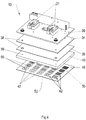
- Fig. 3 is an exploded view of an embodiment of an upper or lower heating device 10, 12 according to the invention.
- the heating device 10, 12 has a support plate 26.
- the carrier plate 26 comprises a receiving surface 28 and a carrier surface 30.
- the carrier element 14 is by means of a carrier mounting unit 31 (see Fig. 2 ) attached to the support surface 30. From the receiving surface 28 protrudes a plurality of screws 32. Preferably, four screws 32 are formed on the receiving surface 28 near a respective corner region of the carrier plate 26. Other arrangements are of course possible.
- the in Fig. 3 illustrated heating device 10, 12 according to the invention an insulating element 34 and a heating mat 36.
- the insulating member 34 is as an insulating formed and is provided for insulating the support plate 26, so that the material of the support plate 26 is not unnecessarily heated at the high temperatures that may occur during heating of the film and losses are avoided.
- the heating mat 36 serves as a heating means to heat the heating plate 40, which will be described later. Other heating means such as heating cartridges are also conceivable.
- the insulating element 34 and the heating mat 36 each have passage openings 38 through which the screws 32 pass, so that the insulating element 34 and subsequently the heating mat 36 can be connected to one another.
- the screws 32 extend into a threaded opening 39 (FIG. Fig. 4 ) of the heating plate 40.
- the heating plate 40 is not penetrated by the screws 32.
- the insulating member 34, the heating mat 36 and the heating plate 40 are usually bolted to the support plate 26 or otherwise firmly connected.
- the heating plate 40 has in the present embodiment, a plurality of different patterns of recesses 42. In Fig. 5 and 6 will be discussed in more detail on the various recesses 42. Furthermore, the heating plate 40 has a plurality of recesses 44 which extend from a Bankplattenober Design 45 of the heating plate 40 into the heating plate 40 inside. In the recesses 44 permanent or permanent magnets 46 are used. The height of the permanent magnets 46 preferably corresponds to the depth of the recesses 44. The recesses 44 are arranged between the edge regions of the heating plate 40 and the recesses 42. Due to the permanent magnets 46, a removable plate 48 is magnetically connected to the heating plate 40. In order to increase the attraction between the heating plate 40 and the removable plate 48, the removable plate 48 may be additionally magnetically coated on the heating plate 40 facing side 50.
- the removable disk 48 has a working surface 52.
- the working surface 52 is arranged on the side facing away from the heating plate 40 of the removable plate 48 and faces the film web.
- the work surface 52 has a substantially smooth surface structure.
- the work surface 52 may also be provided with a non-stick coating.
- the support plate 26, the insulating member 34, the heating mat 36, the heating plate 40 and the removable plate 48 are shown spaced from each other. In reality, lie these individual elements directly to each other. Furthermore, the individual elements 26, 34, 36, 40 and 48 preferably all have the same cross-sectional shape, ie the same dimensions in length and width. In the present embodiment, all plate-like elements 26, 34, 36, 40 and 48 have a rectangular cross-section. However, it is also conceivable that the plate-like elements 26, 34, 36, 40 and 48 may have other shapes depending on the requirement.
- a further embodiment of the heating device 10, 12 according to the invention is shown.
- the structure of the heating device 10, 12 is the structure of the heater 10, 12 in Fig. 3 similar. It differs in that the recesses 42 are formed in the removable plate 48 instead of in the heating plate 40.
- the removable plate 48 in Fig. 4 in turn has the working surface 52 and a heating plate 40 facing side 50, wherein on the heating plate 40 facing side 50, the recesses 42 are formed.
- at least one subunit of the carrier mounting unit 31 is shown, which is fixedly connected to the carrier plate 26 on the carrier surface 30.
- Fig. 3 is the plurality of recesses 42 which are formed in the heating plate 40, covered by the removable plate 48 and in Fig. 4
- the plurality of recesses 42 which are formed in the removable plate 48, covered by the heating plate 40.
- a plurality of cavities 60 are formed between the heating plate 40 and the removable plate 48.
- the plurality of cavities 60 is preferably filled with air.
- both the heating plate 40 and the removable plate 48 have recesses 42 at the same time.
- the recesses 42 in the heating plate 40 and in the removable plate 48 may be identical, so that, for example, the recess 42 in the heating plate 40 are covered by the recesses 42 in the removable plate 48.
- Fig. 3 and 4 exemplified recesses 42 in the heating plate 40 or the removable plate 48 are in Fig. 5 once more clearly shown.
- Fig. 5 illustrated embodiment of the heater substantially corresponds to the embodiment of Fig. 3 , but here the heating plate 40 simultaneously assumes the function of a support plate. An independent support plate is therefore no longer available.
- a plan view of a plurality of different patterns of the recesses 42 is shown by way of example in the heating plate 40.
- the same patterns, which are shown here on the heating plate 40 may also be present on the removable plate 48.
- normally all recesses 42 of a heating plate 40 and a removable plate 48 have the same pattern and this is formed over the entire surface of the respective plate.
- the illustration is only a simple overview of possible patterns and configurations of individual recesses.
- the recesses 42 are in Fig. 6 and Fig. 7 formed in a predetermined pattern on the heating plate 40 or the removable plate 48.
- the predetermined pattern may have any shape.
- the recesses 42 are distributed in a regular pattern on the heating plate 40 or the removable plate 48.
- the recesses 42 are distributed in rows and columns on the heating plate 40 or the removable plate 48. Between the individual rows and columns, the heating plate 40 in Fig. 6 and 7 the recesses 44 into which the permanent magnets 46 are inserted, as already described above.
- the recesses 42 are each formed in the heating plate 40 or removable plate 48 as sinks.
- the depth of the recesses 42 may vary depending on the requirements conditions.
- the depth of the recesses 42 is dependent on the desired temperature gradient or temperature profile.
- the working surface 52 of the removable plate 48 has a lower temperature than in the recessless areas.
- the temperature can be up to about 60% lower than in the recessless areas.
- the recesses 42 may have a depth of between 0.05 mm and 1.00 mm, preferably between 0.10 mm and 0.50 mm.
- a single or multiple elevations 56 may be formed.
- the elevations 56 extend from a bottom 58 of the respective recess 42.
- the height of the elevations 56 may also vary depending on the requirement profile.
- the survey 56 for example, equal to the depth of the recess 42nd be or have a lower level. However, the height of the protrusion 56 can not be greater than the depth of the recess 42.
- the configuration of the recesses 42 may be different. There are all possible forms conceivable.
Landscapes
- Engineering & Computer Science (AREA)
- Mechanical Engineering (AREA)
- Blow-Moulding Or Thermoforming Of Plastics Or The Like (AREA)
Description
- Die vorliegende Erfindung betrifft eine Heizvorrichtung zum Erwärmen einer Folie.
- Derartige Heizvorrichtungen werden standardmäßig in Thermoformmaschinen verwendet und dienen dem Aufheizen der Folie vor der Verformung. Ein spezieller Anwendungsbereich sind Thermoformmaschinen für die Herstellung von Blisterverpackungen in der pharmazeutischen Industrie, aber auch in anderen Branchen, etwa für die Verpackung von Kosmetik- oder Körperpflegeprodukten sowie von Lebensmitteln. Um einen hohen Wärmeübertrag zu erreichen, werden diese Heizplatten als Kontaktheizplatten ausgebildet. Eine derartige Heizvorrichtung besteht üblicherweise aus einer Trägerplatte und einer damit verbundenen Heizplatte. Auf der Heizplatte kann eine Wechselplatte angeordnet sein, die in Kontakt mit der Folie kommt. Zur Gewährleistung eines guten Wärmeübertrags sind Heizplatte und Wechselplatte flächig miteinander verbunden. Die Verbindung zwischen Heizplatte und Wechselplatte kann gemäß
EP 2 390 084 A1 über in die Heizplatte eingefügte Magnete erfolgen. - Eine Heizvorrichtung, die ein Temperaturprofil in der Folienbahn erzeugt, ist in
EP 0 435 234 A2 offenbart. Die Heizvorrichtung umfasst ein Paar an oberen und unteren Heizplatten, die in Richtung der Folienbahn und von der Folienbahn weg bewegbar sind. Die Heizplatten weisen Erhebungen und Senken auf. Die Erhebungen sind näher zu der Folienbahn hin ausgerichtet, d.h. der Kontakt mit der Folienbahn ist lediglich an den Erhebungen vorhanden und im Bereich der Erhebungen wirkt eine höhere Temperatur auf die Folienbahn als in den Bereichen, in denen die Senken ausgebildet sind. Hierdurch wird ein Temperaturprofil in der Folienbahn erzeugt. Im Bereich der Senken fällt die Temperatur allerdings unkontrolliert und rasch ab, was beim Recken der Folie während des Formprozesses zu ungünstiger Dickenverteilung in der Form führen. - Eine Heizvorrichtung nach dem Oberbegriff des Anspruchs 1 ist in
EP2390084 A1 offenbart. - Es ist die Aufgabe der vorliegenden Erfindung, eine Heizvorrichtung zum Erwärmen einer Folie zu schaffen, die auf einfache Weise ein definiertes und kontrolliertes Temperaturprofil über die gesamte Folienbahn erzeugt.
- Diese Aufgabe wird durch die Merkmale des Anspruchs 1 gelöst.
- Erfindungsgemäß umfasst die Heizvorrichtung zum Erwärmen einer Folie eine Heizplatte und eine Wechselplatte, die mit der Heizplatte verbunden ist. Mindestens eine von Heizplatte und Wechselplatte weist eine oder vorzugsweise eine Vielzahl an Ausnehmungen auf. Weiterhin sind die Heizplatte und die Wechselplatte derart miteinander verbunden, dass die eine oder die Vielzahl an Ausnehmungen mit der anderen von Heizplatte und Wechselplatte überdeckt ist, so dass ein oder vorzugsweise eine Vielzahl an Hohlräumen zwischen der Heizplatte und der Wechselplatte ausgebildet ist. Die Hohlräume sind mit Luft befüllt.
- Die Wechselplatte weist somit eine durchgehende Arbeitsfläche auf, die eben ist und während des Heizvorgangs mit der zu erwärmenden Folie in Kontakt ist, wobei aber trotzdem durch den oder die verdeckten Hohlräume ein definiertes Temperaturprofil in der Folienbahn erzeugt werden kann. Zudem besitzt Luft eine gute Eignung zur Wärmeisolierung.
- Von besonderem Vorteil ist es, wenn die Heizplatte Aussparungen aufweist, in denen Dauermagnete aufgenommen sind, die die Wechselplatte magnetisch mit der Heizplatte verbinden. Auf diese Weise kann die Wechselplatte einfach von der Heizplatte getrennt und ausgetauscht werden. Gleichzeitig wird durch die magnetische Verbindung eine sichere Anhaftung der Wechselplatte an der Heizplatte während des Betriebs gewährleistet.
- Eine besonders gute Anhaftung der Wechselplatte an der Heizplatte wird dadurch geschaffen, dass die Wechselplatte vorzugsweise auf der der Heizplatte zugewandten Seite mit einem magnetisch anziehbaren Material beschichtet ist.
- Die Vielzahl an Ausnehmungen ist in einer ersten Gestaltung in der Heizplatte ausgebildet und ist von der Wechselplatte überdeckt. Dadurch sind die Ausnehmungen sehr nah an dem zu bearbeitenden Bereich der Folienbahn angeordnet, um das gewünschte Temperaturprofil in der Folienbahn zu erzeugen, wobei gleichzeitig eine glatte Arbeitsfläche der Wechselplatte zum Erwärmen der Folienbahn beibehalten werden kann.
- Wenn alternativ die Vielzahl an Ausnehmungen in der Wechselplatte ausgebildet ist und von der Heizplatte überdeckt ist, ist aufgrund der Austauschbarkeit der Wechselplatte ein einfacherer Wechsel zu anderen Geometrien und Strukturen der Ausnehmungen für verschiedene Anwendungsbereiche möglich.
- Vorteilhafterweise sind die Ausnehmungen in einem vorbestimmten Muster auf der Heizplatte oder der Wechselplatte verteilt. Durch das vorbestimmte Muster kann gezielt ein vorbestimmtes Temperaturprofil in der Folienbahn erzeugt werden.
- Vorzugsweise sind die Ausnehmungen in einem regelmäßigen Muster auf der Heizplatte oder der Wechselplatte verteilt, wodurch ein Temperaturprofil mit homogenem Verlauf erreicht wird.
- Für viele Anwendungen ist es dabei sinnvoll, wenn die Ausnehmung in Zeilen und Spalten auf der Heizplatte oder Wechselplatte angeordnet sind.
- Um ein besonders differenziertes Temperaturprofil in der Folienbahn erzeugen zu können, können in den Ausnehmungen Erhebungen ausgebildet sein, die sich von einem Boden der Ausnehmung aus erstrecken. Insbesondere soll damit das Temperaturprofil auch im Bereich niedriger Temperatur homogen gestaltet werden.
- Vorzugsweise weisen die Ausnehmungen eine Tiefe von zwischen 0,05 mm und 1,00 mm, bevorzugt zwischen 0,10 mm und 0,50 mm auf. Diese Tiefen haben sich als geeignet zur Einstellung eines Temperaturprofils für die meisten Anwendungen erwiesen.
- Vorteilhafterweise ist auch eine Trägerplatte vorgesehen, die mit der Heizplatte verbunden ist. Die Heizplatte ist vorzugsweise zwischen Trägerplatte und Wechselplatte angeordnet.
- Damit lediglich die Heizplatte und die Wechselplatte aufgeheizt werden, ist vorteilhafterweise zwischen der Trägerplatte und der Heizplatte ein Isolierelement angeordnet.
- Eine Heizmatte ist vorzugsweise zwischen der Trägerplatte und der Heizplatte angeordnet, wodurch eine besonders gute Erwärmung der Heizplatte und somit der Wechselplatte erfolgen kann.
- Eine Heizeinheit umfasst mindestens zwei Heizvorrichtungen, die gegenüberliegend angeordnet sind und von denen mindestens eine relativ zur anderen bewegbar ist, wobei mindestens eine Heizvorrichtung wie oben beschrieben ausgebildet ist.
- Eine Thermoformmaschine zum Formen von Näpfen in eine Folie umfasst mindestens eine Heizvorrichtung zum Erwärmen einer Folie oder eine Heizeinheit wie oben beschrieben.
- Weitere Eigenschaften und Vorteile der vorliegenden Erfindung ergeben sich aus der nachfolgenden Beschreibung unter Bezugnahme auf die Zeichnungen:
- Fig. 1
- ist eine Frontansicht einer Ausführungsform einer Thermoformmaschine mit einer Heizeinheit mit mindestens einer erfindungsgemäßen Heizvorrichtung;
- Fig. 2
- ist eine Perspektivansicht einer Heizeinheit mit zwei erfindungsgemäßen Heizvorrichtungen;
- Fig. 3
- ist eine Explosionsansicht einer Ausführungsform der erfindungsgemäßen Heizvorrichtung;
- Fig. 4
- ist eine Explosionsansicht einer weiteren Ausführungsform der erfindungsgemäßen Heizvorrichtung;
- Fig. 5
- ist eine Explosionsansicht einer weiteren Ausführungsform der erfindungsgemäßen Heizvorrichtung;
- Fig. 6
- ist eine Draufsicht auf eine Ausführungsform einer Heizplatte mit verschiedenen Ausnehmungsmustern; und
- Fig. 7
- ist eine Draufsicht auf eine Ausführungsform einer Heizplatte mit weiteren verschiedenen Ausnehmungsmustern.
- In
Fig. 1 ist eine Thermoformmaschine 2 zum Formen von Näpfen in einer Folienbahn gezeigt. Die Thermoformmaschine 2 weist eine Ausführungsform einer erfindungsgemäßen Heizeinheit 4 und eine Formstation 6 auf. Die Thermoformmaschine 2 umfasst weiterhin eine Fördereinheit 8 zum Fördern einer Folie (nicht dargestellt). Im vorliegenden Ausführungsbeispiel weist die Thermoformmaschine 2 eine Förderrichtung F auf, die hier von links nach rechts verläuft, so dass die Heizeinheit 4 vor der Formstation 6 angeordnet ist. Die Folie wird zunächst von der Fördereinheit 8 in die Heizeinheit 4 befördert und wird dort auf eine bestimmte Temperatur erwärmt. Anschließend wird die erwärmte Folie in der Formstation 6 in die gewünschte Form geformt. - In
Fig. 2 ist ein Ausschnitt der Heizeinheit 4 ausFig. 1 vergrößert dargestellt. Die Heizeinheit 4 umfasst im vorliegenden Ausführungsbeispiel eine obere Heizvorrichtung 10 und eine untere Heizvorrichtung 12. Die obere und die untere Heizvorrichtung 10, 12 sind jeweils über ein Trägerelement 14 an einem verschiebbaren Schlitten 15 befestigt. Der Schlitten 15 wiederum ist an einer zur Förderrichtung F vertikal ausgerichteten Schiene 16 verschiebbar gelagert. Der Schlitten 15 der oberen Heizvorrichtung 10 und der Schlitten 15 der unteren Heizvorrichtung 12 sind jeweils über ein Verbindungselement 18 an gegenüberliegenden Seiten einer gemeinsamen Drehgelenksplatte 20 drehbar gelagert. Die Drehgelenksplatte 20 ist wiederum mit einem Drehgelenk 22 verbunden. Das Drehgelenk 22 ist von einer Antriebseinheit 24 angetrieben und bewegt die obere Heizvorrichtung 10 und die untere Heizvorrichtung 12 relativ zueinander, so dass ein Spalt, der zwischen der oberen Heizvorrichtung 10 und der unteren Heizvorrichtung 12 vorhanden ist und durch den die Folienbahn verläuft, entweder vergrößert oder bis zum Kontakt mit der Folie verkleinert wird. - Denkbar ist aber auch, dass die Heizeinheit 4 der Thermoformmaschine 2 nur eine erfindungsgemäße Heizvorrichtung 10, 12 aufweist und die der erfindungsgemäßen Heizvorrichtung 10, 12 gegenüberliegenden Heizvorrichtung eine herkömmliche Heizvorrichtung ist. Ebenso sind viele andere Gestaltungen des Bewegungsmechanismus der Heizeinheit 4 möglich.
-
Fig. 3 ist eine Explosionsansicht einer Ausführungsform einer erfindungsgemäßen oberen oder unteren Heizvorrichtung 10, 12. Die Heizvorrichtung 10, 12 weist eine Trägerplatte 26 auf. Die Trägerplatte 26 umfasst eine Aufnahmefläche 28 und eine Trägerfläche 30. Das Trägerelement 14 ist mittels einer Trägerbefestigungseinheit 31 (sieheFig. 2 ) an der Trägerfläche 30 befestigt. Von der Aufnahmefläche 28 ragt eine Vielzahl von Schrauben 32 ab. Vorzugsweise sind vier Schrauben 32 auf der Aufnahmefläche 28 jeweils nahe einem Eckbereich der Trägerplatte 26 ausgebildet. Andere Anordnungen sind selbstverständlich möglich. - Weiterhin umfasst die in
Fig. 3 abgebildete erfindungsgemäße Heizvorrichtung 10, 12 ein Isolierelement 34 und eine Heizmatte 36. Das Isolierelement 34 ist als eine Isolierplatte ausgebildet und ist zum Isolieren der Trägerplatte 26 vorgesehen, damit das Material der Trägerplatte 26 bei den hohen Temperaturen, die beim Erwärmen der Folie auftreten können, nicht unnötig aufgeheizt wird und Verluste vermieden werden. Die Heizmatte 36 dient als Heizmittel, um die Heizplatte 40 aufzuheizen, die weiter unten beschrieben wird. Andere Heizmittel wie Heizpatronen sind ebenfalls denkbar. Das Isolierelement 34 und die Heizmatte 36 weisen jeweils Durchgangsöffnungen 38 auf, durch die die Schrauben 32 hindurchverlaufen, so dass das Isolierelement 34 und nachfolgend die Heizmatte 36 miteinander verbunden werden können. - Vorzugsweise erstrecken sich die Schrauben 32 bis in eine Gewindeöffnung 39 (
Fig. 4 ) der Heizplatte 40 hinein. Die Heizplatte 40 wird jedoch nicht von den Schrauben 32 durchdrungen. Das Isolierelement 34, die Heizmatte 36 und die Heizplatte 40 sind üblicherweise mit der Trägerplatte 26 verschraubt oder anderweitig fest verbunden. - Die Heizplatte 40 weist im vorliegenden Ausführungsbeispiel eine Vielzahl von verschiedenen Mustern an Ausnehmungen 42 auf. In
Fig. 5 und6 wird näher auf die verschiedenen Ausnehmungen 42 eingegangen. Des Weiteren weist die Heizplatte 40 eine Vielzahl an Aussparungen 44 auf, die sich von einer Heizplattenoberfläche 45 der Heizplatte 40 aus in die Heizplatte 40 hinein erstrecken. In den Aussparungen 44 sind Permanent- bzw. Dauermagnete 46 eingesetzt. Die Höhe der Dauermagnete 46 entspricht vorzugsweise der Tiefe der Aussparungen 44. Die Aussparungen 44 sind zwischen den Randbereichen der Heizplatte 40 und den Ausnehmungen 42 angeordnet. Durch die Dauermagnete 46 ist eine Wechselplatte 48 magnetisch mit der Heizplatte 40 verbunden. Um die Anziehungskraft zwischen der Heizplatte 40 und der Wechselplatte 48 zu erhöhen, kann die Wechselplatte 48 auf der der Heizplatte 40 zugewandten Seite 50 zusätzlich magnetisch beschichtet sein. - Weiterhin weist die Wechselplatte 48 eine Arbeitsfläche 52 auf. Die Arbeitsfläche 52 ist auf der der Heizplatte 40 abgewandten Seite der Wechselplatte 48 angeordnet und ist der Folienbahn zugewandt. Die Arbeitsfläche 52 weist im Wesentlichen eine glatte Oberflächenstruktur auf. Die Arbeitsfläche 52 kann auch mit einer Antihaftbeschichtung ausgestattet sein.
- In
Fig. 3 und4 ist die Trägerplatte 26, das Isolierelement 34, die Heizmatte 36, die Heizplatte 40 und die Wechselplatte 48 voneinander beabstandet dargestellt. In Wirklichkeit liegen diese einzelnen Elemente direkt aufeinander. Des Weiteren weisen die einzelnen Elemente 26, 34, 36, 40 und 48 vorzugsweise alle die gleiche Querschnittsform, d.h. die gleichen Abmessungen in Länge und Breite, auf. Im vorliegenden Ausführungsbeispiel haben alle plattenartigen Elemente 26, 34, 36, 40 und 48 einen rechteckigen Querschnitt ausgebildet. Vorstellbar ist aber auch, dass die plattenartigen Elemente 26, 34, 36, 40 und 48 je nach Anforderung andere Formen aufweisen können. - In
Fig. 4 ist eine weitere Ausführungsform der erfindungsgemäßen Heizvorrichtung 10, 12 dargestellt. Der Aufbau der Heizvorrichtung 10, 12 ist dem Aufbau der Heizvorrichtung 10, 12 inFig. 3 ähnlich. Er unterscheidet sich darin, dass die Ausnehmungen 42 in der Wechselplatte 48 statt in der Heizplatte 40 ausgebildet sind. Die Wechselplatte 48 inFig. 4 weist wiederum die Arbeitsfläche 52 und eine der Heizplatte 40 zugewandte Seite 50 auf, wobei auf der der Heizplatte 40 zugewandten Seite 50 die Ausnehmungen 42 ausgebildet sind. Des Weiteren ist inFig. 4 zumindest eine Teileinheit der Trägerbefestigungseinheit 31 dargestellt, die fest auf der Trägerfläche 30 mit der Trägerplatte 26 verbunden ist. - In
Fig. 3 wird die Vielzahl an Ausnehmungen 42, die in der Heizplatte 40 ausgebildet sind, von der Wechselplatte 48 überdeckt und inFig. 4 wird die Vielzahl an Ausnehmungen 42, die in der Wechselplatte 48 ausgebildet sind, von der Heizplatte 40 überdeckt. In beiden Fällen wird eine Vielzahl an Hohlräumen 60 zwischen der Heizplatte 40 und der Wechselplatte 48 gebildet. Die Vielzahl an Hohlräumen 60 ist vorzugsweise mit Luft gefüllt. Es ist aber auch denkbar, dass sowohl Heizplatte 40 als auch die Wechselplatte 48 gleichzeitig Ausnehmungen 42 aufweisen. Dabei können die Ausnehmungen 42 in der Heizplatte 40 und in der Wechselplatte 48 identisch sein, so dass beispielsweise die Ausnehmung 42 in der Heizplatte 40 von den Ausnehmungen 42 in der Wechselplatte 48 überdeckt werden. Die inFig. 3 und4 beispielhaft abgebildeten Ausnehmungen 42 in der Heizplatte 40 oder der Wechselplatte 48 sind inFig. 5 noch einmal deutlicher dargestellt. - Die in
Fig. 5 dargestellte Ausführungsform der Heizvorrichtung entspricht im Wesentlichen der ausführungsform ausFig. 3 , allerdings übernimmt hier die Heizplatte 40 gleichzeitig die Funktion einer Trägerplatte. Eine eigenständige Trägerplatte liegt somit nicht mehr vor. - In den
Fig. 6 und7 ist jeweils eine Draufsicht auf mehrere verschiedene Muster der Ausnehmungen 42 beispielhaft in der Heizplatte 40 abgebildet. Es versteht sich jedoch von selbst, dass dieselben Muster, die hier auf der Heizplatte 40 abgebildet sind, auch auf der Wechselplatte 48 vorliegen können. Des Weiteren versteht sich von selbst, dass normalerweise alle Ausnehmungen 42 einer Heizplatte 40 bzw. einer Wechselplatte 48 dasselbe Muster aufweisen und dieses über die gesamte Fläche der jeweiligen Platte ausgebildet ist. Die Darstellung dient nur einer einfachen Übersicht über mögliche Muster und Ausgestaltungen einzelner Ausnehmungen. - Die Ausnehmungen 42 sind in
Fig. 6 undFig. 7 in einem vorbestimmten Muster auf der Heizplatte 40 oder der Wechselplatte 48 ausgebildet. Das vorbestimmte Muster kann eine beliebige Form aufweisen. Vorzugsweise sind die Ausnehmungen 42 in einem regelmäßigen Muster auf der Heizplatte 40 oder der Wechselplatte 48 verteilt. In den vorliegenden Ausführungsbeispielen sind die Ausnehmungen 42 in Zeilen und Spalten auf der Heizplatte 40 oder der Wechselplatte 48 verteilt. Zwischen den einzelnen Zeilen und Spalten weist die Heizplatte 40 inFig. 6 und7 die Aussparungen 44 auf, in die die Dauermagnete 46 eingesetzt werden, wie bereits oben beschrieben wurde. - Die Ausnehmungen 42 sind jeweils in der Heizplatte 40 oder Wechselplatte 48 als Senken ausgebildet. Dabei kann die Tiefe der Ausnehmungen 42 je nach Anforderungsbedingungen variieren.
- Die Tiefe der Ausnehmungen 42 ist abhängig von dem gewünschten Temperaturgefälle bzw. Temperaturprofil. Im Bereich der Ausnehmungen 42 weist die Arbeitsfläche 52 der Wechselplatte 48 eine geringere Temperatur auf als in den ausnehmungslosen Bereichen. Im Bereich der Ausnehmungen 42 kann die Temperatur so bis etwa 60 % niedriger sein als in den ausnehmungslosen Bereichen.
- Die Ausnehmungen 42 können eine Tiefe von zwischen 0,05 mm und 1,00 mm, bevorzugt zwischen 0,10 mm und 0,50 mm, aufweisen.
- In den einzelnen Ausnehmungen 42 können eine einzelne oder mehrere Erhebungen 56 ausgebildet sein. Die Erhebungen 56 erstrecken sich von einem Boden 58 der jeweiligen Ausnehmung 42 aus. Die Höhe der Erhebungen 56 kann ebenfalls je nach Anforderungsprofil variieren. Die Erhebung 56 kann beispielsweise gleich der Tiefe der Ausnehmung 42 sein oder ein geringeres Maß aufweisen. Jedoch kann die Höhe der Erhebung 56 nicht größer als die Tiefe der Ausnehmung 42 sein.
- Des Weiteren kann die Ausgestaltung der Ausnehmungen 42 unterschiedlich sein. Es sind alle möglichen Formen denkbar.
Claims (15)
- Heizvorrichtung (10, 12) zum Erwärmen einer Folie, mit
einer Heizplatte (40), und
einer Wechselplatte (48), die mit der Heizplatte (40) verbunden ist,
wobei mindestens eine von Heizplatte (40) und Wechselplatte (48) eine Ausnehmung (42) oder eine Vielzahl an Ausnehmungen (42) aufweist, und
die Heizplatte (40) und die Wechselplatte (48) derart miteinander verbunden sind, dass die Ausnehmung (42) oder die Vielzahl an Ausnehmungen (42) mit der anderen von Heizplatte (40) und Wechselplatte (48) überdeckt ist, so dass ein Hohlraum (60) oder eine Vielzahl an Hohlräumen (60) zwischen der Heizplatte (40) und der Wechselplatte (48) ausgebildet ist,
dadurch gekennzeichnet, dass jeder Hohlraum (60) mit Luft gefüllt ist. - Heizvorrichtung (10, 12) nach Anspruch 1, dadurch gekennzeichnet, dass die Heizplatte (40) Aussparungen (44) aufweist, in denen Dauermagnete (46) aufgenommen sind, die die Wechselplatte (48) magnetisch mit der Heizplatte (40) verbinden.
- Heizvorrichtung (10, 12) nach Anspruch 1 oder 2, dadurch gekennzeichnet, dass die Wechselplatte (48) auf der der Heizplatte (40) zugewandten Seite mit einem magnetisch anziehbaren Material beschichtet ist.
- Heizvorrichtung (10, 12) nach einem der vorangehenden Ansprüche, dadurch gekennzeichnet, dass jede Ausnehmung (42) in der Heizplatte (40) ausgebildet ist und von der Wechselplatte (48) überdeckt ist.
- Heizvorrichtung (10, 12) nach einem der Ansprüche 1 bis 4, dadurch gekennzeichnet, dass jede Ausnehmung (42) in der Wechselplatte (48) ausgebildet ist und von der Heizplatte (40) überdeckt ist.
- Heizvorrichtung (10, 12) nach einem der vorangehenden Ansprüche, dadurch gekennzeichnet, dass die Ausnehmungen (42) in einem vorbestimmten Muster auf der Heizplatte (40) oder der Wechselplatte (48) verteilt sind.
- Heizvorrichtung (10, 12) nach Anspruch 6, dadurch gekennzeichnet, dass die Ausnehmungen (42) in einem regelmäßigen Muster auf der Heizplatte (40) oder der Wechselplatte (48) verteilt sind.
- Heizvorrichtung (10, 12) nach einem der vorangehenden Ansprüche, dadurch gekennzeichnet, dass die Ausnehmungen (42) in Zeilen und Spalten auf der Heizplatte oder der Wechselplatte (48) angeordnet sind.
- Heizvorrichtung (10, 12) nach einem der vorangehenden Ansprüche, dadurch gekennzeichnet, dass in den Ausnehmungen (42) Erhebungen (56) ausgebildet sind, die sich von einem Boden (58) der Ausnehmungen (42) aus erstrecken.
- Heizvorrichtung (10, 12) nach einem der vorangehenden Ansprüche, dadurch gekennzeichnet, dass die Ausnehmungen (42) eine Tiefe von zwischen 0,05 mm und 1,00 mm, bevorzugt zwischen 0,10 mm und 0,50 mm aufweisen.
- Heizvorrichtung (10, 12) nach einem der vorangehenden Ansprüche, dadurch gekennzeichnet, dass sie außerdem eine Trägerplatte (26) aufweist, die mit der Heizplatte (40) verbunden ist, wobei die Heizplatte (40) zwischen der Trägerplatte (26) und der Wechselplatte (48) angeordnet ist.
- Heizvorrichtung (10, 12) nach Anspruch 11, dadurch gekennzeichnet, dass zwischen der Trägerplatte (26) und der Heizplatte (40) ein Isolierelement (34) angeordnet ist.
- Heizvorrichtung (10, 12) nach Anspruch 11 oder 12, dadurch gekennzeichnet, dass zwischen der Trägerplatte (26) und der Heizplatte (40) eine Heizmatte (36) angeordnet ist.
- Heizeinheit (4) mit mindestens zwei Heizvorrichtungen (10, 12), die gegenüberliegend angeordnet sind und von denen mindestens eine relativ zur anderen bewegbar ist, wobei mindestens eine Heizvorrichtung (10, 12) nach einem der vorangehenden Ansprüche ausgebildet ist.
- Thermoformmaschine (2) zum Formen von Näpfen in eine Folie zur Erzeugung einer Blisterbahn, mit mindestens einer Heizvorrichtung (10, 12) zum Erwärmen der Folie nach einem der Ansprüche 1 bis 13 oder einer Heizeinheit (4) nach Anspruch 14.
Priority Applications (1)
| Application Number | Priority Date | Filing Date | Title |
|---|---|---|---|
| EP16152933.4A EP3078478B1 (de) | 2015-04-09 | 2016-01-27 | Heizvorrichtung zum erwärmen einer folie |
Applications Claiming Priority (2)
| Application Number | Priority Date | Filing Date | Title |
|---|---|---|---|
| EP15162889 | 2015-04-09 | ||
| EP16152933.4A EP3078478B1 (de) | 2015-04-09 | 2016-01-27 | Heizvorrichtung zum erwärmen einer folie |
Publications (2)
| Publication Number | Publication Date |
|---|---|
| EP3078478A1 EP3078478A1 (de) | 2016-10-12 |
| EP3078478B1 true EP3078478B1 (de) | 2019-08-28 |
Family
ID=52997846
Family Applications (1)
| Application Number | Title | Priority Date | Filing Date |
|---|---|---|---|
| EP16152933.4A Active EP3078478B1 (de) | 2015-04-09 | 2016-01-27 | Heizvorrichtung zum erwärmen einer folie |
Country Status (2)
| Country | Link |
|---|---|
| EP (1) | EP3078478B1 (de) |
| ES (1) | ES2751657T3 (de) |
Cited By (5)
| Publication number | Priority date | Publication date | Assignee | Title |
|---|---|---|---|---|
| WO2022002968A3 (de) * | 2020-07-01 | 2022-03-17 | Gea Food Solutions Germany Gmbh | Siegelwerkzeug mit einem heizmittel |
| EP4257336A1 (de) * | 2022-04-04 | 2023-10-11 | Henkel AG & Co. KGaA | Waschmittelportionseinheiten |
| EP4257335A1 (de) * | 2022-04-04 | 2023-10-11 | Henkel AG & Co. KGaA | Verfahren zur herstellung von waschmittelportionseinheiten |
| EP4257334A1 (de) * | 2022-04-04 | 2023-10-11 | Henkel AG & Co. KGaA | Heizvorrichtung |
| EP4368368A1 (de) * | 2022-11-10 | 2024-05-15 | Harro Höfliger Verpackungsmaschinen GmbH | Tiefziehvorrichtung, verpackungsmaschine mit einer tiefziehvorrichtung und verfahren zum betrieb der tiefziehvorrichtung |
Family Cites Families (4)
| Publication number | Priority date | Publication date | Assignee | Title |
|---|---|---|---|---|
| US3386503A (en) * | 1966-02-24 | 1968-06-04 | Continental Can Co | Differential heating plate |
| JPH0694161B2 (ja) | 1989-12-28 | 1994-11-24 | 出光石油化学株式会社 | 熱可塑性樹脂シートの熱成形方法及び装置 |
| US20120131730A1 (en) * | 2007-08-10 | 2012-05-31 | Gilad Shoham | Contoured Face Shields and Method of Producing Optically Clear Parts |
| EP2390084B1 (de) | 2010-05-26 | 2012-07-18 | UHLMANN PAC-SYSTEME GmbH & Co. KG | Heizplatte zum Erwärmen einer Folie |
-
2016
- 2016-01-27 ES ES16152933T patent/ES2751657T3/es active Active
- 2016-01-27 EP EP16152933.4A patent/EP3078478B1/de active Active
Non-Patent Citations (1)
| Title |
|---|
| None * |
Cited By (9)
| Publication number | Priority date | Publication date | Assignee | Title |
|---|---|---|---|---|
| WO2022002968A3 (de) * | 2020-07-01 | 2022-03-17 | Gea Food Solutions Germany Gmbh | Siegelwerkzeug mit einem heizmittel |
| EP4420991A3 (de) * | 2020-07-01 | 2024-09-04 | Gea Food Solutions Germany GmbH | Siegelwerkzeug mit einem heizmittel |
| EP4257336A1 (de) * | 2022-04-04 | 2023-10-11 | Henkel AG & Co. KGaA | Waschmittelportionseinheiten |
| EP4257335A1 (de) * | 2022-04-04 | 2023-10-11 | Henkel AG & Co. KGaA | Verfahren zur herstellung von waschmittelportionseinheiten |
| EP4257334A1 (de) * | 2022-04-04 | 2023-10-11 | Henkel AG & Co. KGaA | Heizvorrichtung |
| WO2023193965A1 (de) * | 2022-04-04 | 2023-10-12 | Henkel Ag & Co. Kgaa | Verfahren zur herstellung von waschmittelportionseinheiten |
| WO2023193964A1 (de) * | 2022-04-04 | 2023-10-12 | Henkel Ag & Co. Kgaa | Heizvorrichtung zur herstellung von waschmitteldosiereinheiten mit verbesserten eigenschaften |
| WO2023193966A1 (de) * | 2022-04-04 | 2023-10-12 | Henkel Ag & Co. Kgaa | Waschmittelportionseinheiten |
| EP4368368A1 (de) * | 2022-11-10 | 2024-05-15 | Harro Höfliger Verpackungsmaschinen GmbH | Tiefziehvorrichtung, verpackungsmaschine mit einer tiefziehvorrichtung und verfahren zum betrieb der tiefziehvorrichtung |
Also Published As
| Publication number | Publication date |
|---|---|
| EP3078478A1 (de) | 2016-10-12 |
| ES2751657T3 (es) | 2020-04-01 |
Similar Documents
| Publication | Publication Date | Title |
|---|---|---|
| EP3078478A1 (de) | Heizvorrichtung zum erwärmen einer folie | |
| EP1426110B1 (de) | Laborthermostat, aufweisend einen Temperierblock mit Temperiereinrichtungen, und Verfahren zu dessen Verwendung | |
| EP0936945B1 (de) | Temperierblock mit aufnahmen | |
| DE3505256C2 (de) | Vorrichtung zum berührungsfreien Führen von Warenbahnen, insbesondere Metallbändern, mittels eines Gasmediums | |
| EP4105006B1 (de) | Vorrichtung zur pressenden bearbeitung von flachmaterial | |
| WO2016192994A1 (de) | Verfahren zum homogenen kontaktlosen temperieren von temperierenden, nicht endlosen oberflächen und vorrichtung hierfür | |
| CH623777A5 (de) | ||
| DE10201830A1 (de) | Düsenende für eine Spritzgussdüse mit mehreren Spitzen | |
| EP3487650B1 (de) | Kokillenplatte und kokille | |
| DE2535989B2 (de) | Vorrichtung zum Aushärten stranggepreBter Körper | |
| DE102004005703B4 (de) | Verfahren und Apparatur zur kontinuierlichen Formung eines Streifens aus Kunststoff mit einem gewellten Profil | |
| DE102015012844A1 (de) | Verfahren und Vorrichtung zur generativen Herstellung eines dreidimensionalen Formkörpers aus einem formlosen Material mittels Laserstrahlschmelzens, sowie Kammervorrichtung für das Verfahren und die Vorrichtung | |
| EP1786737B1 (de) | Schaumglaskühlstrecke | |
| EP3181528B1 (de) | Förderkette zum transport von glasbehältern durch einen ofen mit als kettenlaschen ausgebildeten stützen sowie fördereinrichtung mit einer solchen förderkette | |
| DE60033667T2 (de) | Nicht rotierendes, zylindrisches luftpolster zur erzeugung einer bandschwebung und verfahren zum stützen und führen eines endlosen flexiblen giessbandes | |
| DE60201862T2 (de) | Thermoformwerkzeug zum formen von Kunststofffolie | |
| DE112005001013T5 (de) | Formverteiler mit geringem Abstand | |
| DE102019113695B4 (de) | Konturplatte zum Aufbringen von Heißgas entlang einer Schweißlinie eines Kunststoffteils, Verfahren zum Herstellen einer Konturplatte und eine Vorrichtung zum Schweißen von Kunststoffteilen | |
| DE4230015C2 (de) | Plattenelement für eine Etagen-Plattenpresse | |
| DE102016108467B3 (de) | Werkzeugvorrichtung | |
| EP4177030A1 (de) | Arbeitsstation für folienverarbeitende verpackungsmaschine | |
| DE4212335C2 (de) | Extrusionsvorrichtung zur Herstellung von Platten | |
| EP3118128B1 (de) | Schrumpfvorrichtung | |
| DE102017127657B3 (de) | Werkzeug für eine Vorrichtung zum wärmegestützten Umformen, insbesondere Warmumformen und/oder Presshärten sowie Vorrichtung und Verfahren zum wärmegestützten Umformen, insbesondere Warmumformen und/oder Presshärten mit wenigstens einem solchen Werkzeug | |
| DE2218557C3 (de) | Vorrichtung zum Herstellen von Wandelementen |
Legal Events
| Date | Code | Title | Description |
|---|---|---|---|
| PUAI | Public reference made under article 153(3) epc to a published international application that has entered the european phase |
Free format text: ORIGINAL CODE: 0009012 |
|
| AK | Designated contracting states |
Kind code of ref document: A1 Designated state(s): AL AT BE BG CH CY CZ DE DK EE ES FI FR GB GR HR HU IE IS IT LI LT LU LV MC MK MT NL NO PL PT RO RS SE SI SK SM TR |
|
| AX | Request for extension of the european patent |
Extension state: BA ME |
|
| STAA | Information on the status of an ep patent application or granted ep patent |
Free format text: STATUS: REQUEST FOR EXAMINATION WAS MADE |
|
| 17P | Request for examination filed |
Effective date: 20170410 |
|
| RBV | Designated contracting states (corrected) |
Designated state(s): AL AT BE BG CH CY CZ DE DK EE ES FI FR GB GR HR HU IE IS IT LI LT LU LV MC MK MT NL NO PL PT RO RS SE SI SK SM TR |
|
| GRAP | Despatch of communication of intention to grant a patent |
Free format text: ORIGINAL CODE: EPIDOSNIGR1 |
|
| STAA | Information on the status of an ep patent application or granted ep patent |
Free format text: STATUS: GRANT OF PATENT IS INTENDED |
|
| INTG | Intention to grant announced |
Effective date: 20190603 |
|
| GRAS | Grant fee paid |
Free format text: ORIGINAL CODE: EPIDOSNIGR3 |
|
| GRAA | (expected) grant |
Free format text: ORIGINAL CODE: 0009210 |
|
| STAA | Information on the status of an ep patent application or granted ep patent |
Free format text: STATUS: THE PATENT HAS BEEN GRANTED |
|
| AK | Designated contracting states |
Kind code of ref document: B1 Designated state(s): AL AT BE BG CH CY CZ DE DK EE ES FI FR GB GR HR HU IE IS IT LI LT LU LV MC MK MT NL NO PL PT RO RS SE SI SK SM TR |
|
| REG | Reference to a national code |
Ref country code: GB Ref legal event code: FG4D Free format text: NOT ENGLISH |
|
| REG | Reference to a national code |
Ref country code: CH Ref legal event code: EP |
|
| REG | Reference to a national code |
Ref country code: DE Ref legal event code: R096 Ref document number: 502016006258 Country of ref document: DE |
|
| REG | Reference to a national code |
Ref country code: AT Ref legal event code: REF Ref document number: 1171865 Country of ref document: AT Kind code of ref document: T Effective date: 20190915 |
|
| REG | Reference to a national code |
Ref country code: IE Ref legal event code: FG4D Free format text: LANGUAGE OF EP DOCUMENT: GERMAN |
|
| REG | Reference to a national code |
Ref country code: NL Ref legal event code: MP Effective date: 20190828 |
|
| REG | Reference to a national code |
Ref country code: LT Ref legal event code: MG4D |
|
| PG25 | Lapsed in a contracting state [announced via postgrant information from national office to epo] |
Ref country code: FI Free format text: LAPSE BECAUSE OF FAILURE TO SUBMIT A TRANSLATION OF THE DESCRIPTION OR TO PAY THE FEE WITHIN THE PRESCRIBED TIME-LIMIT Effective date: 20190828 Ref country code: HR Free format text: LAPSE BECAUSE OF FAILURE TO SUBMIT A TRANSLATION OF THE DESCRIPTION OR TO PAY THE FEE WITHIN THE PRESCRIBED TIME-LIMIT Effective date: 20190828 Ref country code: BG Free format text: LAPSE BECAUSE OF FAILURE TO SUBMIT A TRANSLATION OF THE DESCRIPTION OR TO PAY THE FEE WITHIN THE PRESCRIBED TIME-LIMIT Effective date: 20191128 Ref country code: SE Free format text: LAPSE BECAUSE OF FAILURE TO SUBMIT A TRANSLATION OF THE DESCRIPTION OR TO PAY THE FEE WITHIN THE PRESCRIBED TIME-LIMIT Effective date: 20190828 Ref country code: NO Free format text: LAPSE BECAUSE OF FAILURE TO SUBMIT A TRANSLATION OF THE DESCRIPTION OR TO PAY THE FEE WITHIN THE PRESCRIBED TIME-LIMIT Effective date: 20191128 Ref country code: LT Free format text: LAPSE BECAUSE OF FAILURE TO SUBMIT A TRANSLATION OF THE DESCRIPTION OR TO PAY THE FEE WITHIN THE PRESCRIBED TIME-LIMIT Effective date: 20190828 Ref country code: NL Free format text: LAPSE BECAUSE OF FAILURE TO SUBMIT A TRANSLATION OF THE DESCRIPTION OR TO PAY THE FEE WITHIN THE PRESCRIBED TIME-LIMIT Effective date: 20190828 Ref country code: PT Free format text: LAPSE BECAUSE OF FAILURE TO SUBMIT A TRANSLATION OF THE DESCRIPTION OR TO PAY THE FEE WITHIN THE PRESCRIBED TIME-LIMIT Effective date: 20191230 |
|
| PG25 | Lapsed in a contracting state [announced via postgrant information from national office to epo] |
Ref country code: GR Free format text: LAPSE BECAUSE OF FAILURE TO SUBMIT A TRANSLATION OF THE DESCRIPTION OR TO PAY THE FEE WITHIN THE PRESCRIBED TIME-LIMIT Effective date: 20191129 Ref country code: LV Free format text: LAPSE BECAUSE OF FAILURE TO SUBMIT A TRANSLATION OF THE DESCRIPTION OR TO PAY THE FEE WITHIN THE PRESCRIBED TIME-LIMIT Effective date: 20190828 Ref country code: AL Free format text: LAPSE BECAUSE OF FAILURE TO SUBMIT A TRANSLATION OF THE DESCRIPTION OR TO PAY THE FEE WITHIN THE PRESCRIBED TIME-LIMIT Effective date: 20190828 Ref country code: IS Free format text: LAPSE BECAUSE OF FAILURE TO SUBMIT A TRANSLATION OF THE DESCRIPTION OR TO PAY THE FEE WITHIN THE PRESCRIBED TIME-LIMIT Effective date: 20191228 Ref country code: RS Free format text: LAPSE BECAUSE OF FAILURE TO SUBMIT A TRANSLATION OF THE DESCRIPTION OR TO PAY THE FEE WITHIN THE PRESCRIBED TIME-LIMIT Effective date: 20190828 |
|
| PG25 | Lapsed in a contracting state [announced via postgrant information from national office to epo] |
Ref country code: TR Free format text: LAPSE BECAUSE OF FAILURE TO SUBMIT A TRANSLATION OF THE DESCRIPTION OR TO PAY THE FEE WITHIN THE PRESCRIBED TIME-LIMIT Effective date: 20190828 |
|
| REG | Reference to a national code |
Ref country code: ES Ref legal event code: FG2A Ref document number: 2751657 Country of ref document: ES Kind code of ref document: T3 Effective date: 20200401 |
|
| PG25 | Lapsed in a contracting state [announced via postgrant information from national office to epo] |
Ref country code: EE Free format text: LAPSE BECAUSE OF FAILURE TO SUBMIT A TRANSLATION OF THE DESCRIPTION OR TO PAY THE FEE WITHIN THE PRESCRIBED TIME-LIMIT Effective date: 20190828 Ref country code: PL Free format text: LAPSE BECAUSE OF FAILURE TO SUBMIT A TRANSLATION OF THE DESCRIPTION OR TO PAY THE FEE WITHIN THE PRESCRIBED TIME-LIMIT Effective date: 20190828 Ref country code: RO Free format text: LAPSE BECAUSE OF FAILURE TO SUBMIT A TRANSLATION OF THE DESCRIPTION OR TO PAY THE FEE WITHIN THE PRESCRIBED TIME-LIMIT Effective date: 20190828 Ref country code: DK Free format text: LAPSE BECAUSE OF FAILURE TO SUBMIT A TRANSLATION OF THE DESCRIPTION OR TO PAY THE FEE WITHIN THE PRESCRIBED TIME-LIMIT Effective date: 20190828 |
|
| PG25 | Lapsed in a contracting state [announced via postgrant information from national office to epo] |
Ref country code: SK Free format text: LAPSE BECAUSE OF FAILURE TO SUBMIT A TRANSLATION OF THE DESCRIPTION OR TO PAY THE FEE WITHIN THE PRESCRIBED TIME-LIMIT Effective date: 20190828 Ref country code: SM Free format text: LAPSE BECAUSE OF FAILURE TO SUBMIT A TRANSLATION OF THE DESCRIPTION OR TO PAY THE FEE WITHIN THE PRESCRIBED TIME-LIMIT Effective date: 20190828 Ref country code: IS Free format text: LAPSE BECAUSE OF FAILURE TO SUBMIT A TRANSLATION OF THE DESCRIPTION OR TO PAY THE FEE WITHIN THE PRESCRIBED TIME-LIMIT Effective date: 20200224 Ref country code: CZ Free format text: LAPSE BECAUSE OF FAILURE TO SUBMIT A TRANSLATION OF THE DESCRIPTION OR TO PAY THE FEE WITHIN THE PRESCRIBED TIME-LIMIT Effective date: 20190828 |
|
| REG | Reference to a national code |
Ref country code: DE Ref legal event code: R097 Ref document number: 502016006258 Country of ref document: DE |
|
| PLBE | No opposition filed within time limit |
Free format text: ORIGINAL CODE: 0009261 |
|
| STAA | Information on the status of an ep patent application or granted ep patent |
Free format text: STATUS: NO OPPOSITION FILED WITHIN TIME LIMIT |
|
| PG2D | Information on lapse in contracting state deleted |
Ref country code: IS |
|
| 26N | No opposition filed |
Effective date: 20200603 |
|
| PG25 | Lapsed in a contracting state [announced via postgrant information from national office to epo] |
Ref country code: MC Free format text: LAPSE BECAUSE OF FAILURE TO SUBMIT A TRANSLATION OF THE DESCRIPTION OR TO PAY THE FEE WITHIN THE PRESCRIBED TIME-LIMIT Effective date: 20190828 Ref country code: SI Free format text: LAPSE BECAUSE OF FAILURE TO SUBMIT A TRANSLATION OF THE DESCRIPTION OR TO PAY THE FEE WITHIN THE PRESCRIBED TIME-LIMIT Effective date: 20190828 |
|
| REG | Reference to a national code |
Ref country code: CH Ref legal event code: PL |
|
| GBPC | Gb: european patent ceased through non-payment of renewal fee |
Effective date: 20200127 |
|
| REG | Reference to a national code |
Ref country code: BE Ref legal event code: MM Effective date: 20200131 |
|
| PG25 | Lapsed in a contracting state [announced via postgrant information from national office to epo] |
Ref country code: GB Free format text: LAPSE BECAUSE OF NON-PAYMENT OF DUE FEES Effective date: 20200127 Ref country code: FR Free format text: LAPSE BECAUSE OF NON-PAYMENT OF DUE FEES Effective date: 20200131 Ref country code: LU Free format text: LAPSE BECAUSE OF NON-PAYMENT OF DUE FEES Effective date: 20200127 |
|
| PG25 | Lapsed in a contracting state [announced via postgrant information from national office to epo] |
Ref country code: CH Free format text: LAPSE BECAUSE OF NON-PAYMENT OF DUE FEES Effective date: 20200131 Ref country code: BE Free format text: LAPSE BECAUSE OF NON-PAYMENT OF DUE FEES Effective date: 20200131 Ref country code: LI Free format text: LAPSE BECAUSE OF NON-PAYMENT OF DUE FEES Effective date: 20200131 |
|
| PG25 | Lapsed in a contracting state [announced via postgrant information from national office to epo] |
Ref country code: IE Free format text: LAPSE BECAUSE OF NON-PAYMENT OF DUE FEES Effective date: 20200127 |
|
| REG | Reference to a national code |
Ref country code: AT Ref legal event code: MM01 Ref document number: 1171865 Country of ref document: AT Kind code of ref document: T Effective date: 20210127 |
|
| PG25 | Lapsed in a contracting state [announced via postgrant information from national office to epo] |
Ref country code: AT Free format text: LAPSE BECAUSE OF NON-PAYMENT OF DUE FEES Effective date: 20210127 |
|
| PG25 | Lapsed in a contracting state [announced via postgrant information from national office to epo] |
Ref country code: MT Free format text: LAPSE BECAUSE OF FAILURE TO SUBMIT A TRANSLATION OF THE DESCRIPTION OR TO PAY THE FEE WITHIN THE PRESCRIBED TIME-LIMIT Effective date: 20190828 Ref country code: CY Free format text: LAPSE BECAUSE OF FAILURE TO SUBMIT A TRANSLATION OF THE DESCRIPTION OR TO PAY THE FEE WITHIN THE PRESCRIBED TIME-LIMIT Effective date: 20190828 |
|
| PG25 | Lapsed in a contracting state [announced via postgrant information from national office to epo] |
Ref country code: MK Free format text: LAPSE BECAUSE OF FAILURE TO SUBMIT A TRANSLATION OF THE DESCRIPTION OR TO PAY THE FEE WITHIN THE PRESCRIBED TIME-LIMIT Effective date: 20190828 |
|
| PGFP | Annual fee paid to national office [announced via postgrant information from national office to epo] |
Ref country code: ES Payment date: 20260202 Year of fee payment: 11 |
|
| PGFP | Annual fee paid to national office [announced via postgrant information from national office to epo] |
Ref country code: DE Payment date: 20260128 Year of fee payment: 11 |
|
| PGFP | Annual fee paid to national office [announced via postgrant information from national office to epo] |
Ref country code: IT Payment date: 20260128 Year of fee payment: 11 |