EP3078464B1 - Cutting device for flexible material - Google Patents
Cutting device for flexible material Download PDFInfo
- Publication number
- EP3078464B1 EP3078464B1 EP14867392.4A EP14867392A EP3078464B1 EP 3078464 B1 EP3078464 B1 EP 3078464B1 EP 14867392 A EP14867392 A EP 14867392A EP 3078464 B1 EP3078464 B1 EP 3078464B1
- Authority
- EP
- European Patent Office
- Prior art keywords
- flexible material
- cutting device
- blade
- bristles
- cut
- Prior art date
- Legal status (The legal status is an assumption and is not a legal conclusion. Google has not performed a legal analysis and makes no representation as to the accuracy of the status listed.)
- Active
Links
- 239000000463 material Substances 0.000 title claims description 86
- 238000005520 cutting process Methods 0.000 title claims description 35
- 230000001154 acute effect Effects 0.000 claims description 5
- 238000000926 separation method Methods 0.000 claims description 3
- 239000004677 Nylon Substances 0.000 claims 1
- 229920001778 nylon Polymers 0.000 claims 1
- 229920002994 synthetic fiber Polymers 0.000 claims 1
- 239000011087 paperboard Substances 0.000 description 5
- 230000037303 wrinkles Effects 0.000 description 5
- 239000013013 elastic material Substances 0.000 description 1
- 230000008030 elimination Effects 0.000 description 1
- 238000003379 elimination reaction Methods 0.000 description 1
- 239000005445 natural material Substances 0.000 description 1
- 230000002093 peripheral effect Effects 0.000 description 1
- 230000006641 stabilisation Effects 0.000 description 1
- 238000011105 stabilization Methods 0.000 description 1
- 230000000087 stabilizing effect Effects 0.000 description 1
Images


Classifications
-
- B—PERFORMING OPERATIONS; TRANSPORTING
- B26—HAND CUTTING TOOLS; CUTTING; SEVERING
- B26D—CUTTING; DETAILS COMMON TO MACHINES FOR PERFORATING, PUNCHING, CUTTING-OUT, STAMPING-OUT OR SEVERING
- B26D7/00—Details of apparatus for cutting, cutting-out, stamping-out, punching, perforating, or severing by means other than cutting
- B26D7/01—Means for holding or positioning work
- B26D7/02—Means for holding or positioning work with clamping means
- B26D7/04—Means for holding or positioning work with clamping means providing adjustable clamping pressure
-
- B—PERFORMING OPERATIONS; TRANSPORTING
- B26—HAND CUTTING TOOLS; CUTTING; SEVERING
- B26D—CUTTING; DETAILS COMMON TO MACHINES FOR PERFORATING, PUNCHING, CUTTING-OUT, STAMPING-OUT OR SEVERING
- B26D1/00—Cutting through work characterised by the nature or movement of the cutting member or particular materials not otherwise provided for; Apparatus or machines therefor; Cutting members therefor
- B26D1/01—Cutting through work characterised by the nature or movement of the cutting member or particular materials not otherwise provided for; Apparatus or machines therefor; Cutting members therefor involving a cutting member which does not travel with the work
- B26D1/02—Cutting through work characterised by the nature or movement of the cutting member or particular materials not otherwise provided for; Apparatus or machines therefor; Cutting members therefor involving a cutting member which does not travel with the work having a stationary cutting member
- B26D1/025—Cutting through work characterised by the nature or movement of the cutting member or particular materials not otherwise provided for; Apparatus or machines therefor; Cutting members therefor involving a cutting member which does not travel with the work having a stationary cutting member for thin material, e.g. for sheets, strips or the like
-
- B—PERFORMING OPERATIONS; TRANSPORTING
- B26—HAND CUTTING TOOLS; CUTTING; SEVERING
- B26D—CUTTING; DETAILS COMMON TO MACHINES FOR PERFORATING, PUNCHING, CUTTING-OUT, STAMPING-OUT OR SEVERING
- B26D1/00—Cutting through work characterised by the nature or movement of the cutting member or particular materials not otherwise provided for; Apparatus or machines therefor; Cutting members therefor
- B26D1/01—Cutting through work characterised by the nature or movement of the cutting member or particular materials not otherwise provided for; Apparatus or machines therefor; Cutting members therefor involving a cutting member which does not travel with the work
- B26D1/04—Cutting through work characterised by the nature or movement of the cutting member or particular materials not otherwise provided for; Apparatus or machines therefor; Cutting members therefor involving a cutting member which does not travel with the work having a linearly-movable cutting member
- B26D1/045—Cutting through work characterised by the nature or movement of the cutting member or particular materials not otherwise provided for; Apparatus or machines therefor; Cutting members therefor involving a cutting member which does not travel with the work having a linearly-movable cutting member for thin material, e.g. for sheets, strips or the like
-
- B—PERFORMING OPERATIONS; TRANSPORTING
- B26—HAND CUTTING TOOLS; CUTTING; SEVERING
- B26D—CUTTING; DETAILS COMMON TO MACHINES FOR PERFORATING, PUNCHING, CUTTING-OUT, STAMPING-OUT OR SEVERING
- B26D7/00—Details of apparatus for cutting, cutting-out, stamping-out, punching, perforating, or severing by means other than cutting
- B26D7/01—Means for holding or positioning work
-
- B—PERFORMING OPERATIONS; TRANSPORTING
- B26—HAND CUTTING TOOLS; CUTTING; SEVERING
- B26D—CUTTING; DETAILS COMMON TO MACHINES FOR PERFORATING, PUNCHING, CUTTING-OUT, STAMPING-OUT OR SEVERING
- B26D7/00—Details of apparatus for cutting, cutting-out, stamping-out, punching, perforating, or severing by means other than cutting
- B26D7/08—Means for treating work or cutting member to facilitate cutting
- B26D7/14—Means for treating work or cutting member to facilitate cutting by tensioning the work
-
- D—TEXTILES; PAPER
- D06—TREATMENT OF TEXTILES OR THE LIKE; LAUNDERING; FLEXIBLE MATERIALS NOT OTHERWISE PROVIDED FOR
- D06H—MARKING, INSPECTING, SEAMING OR SEVERING TEXTILE MATERIALS
- D06H7/00—Apparatus or processes for cutting, or otherwise severing, specially adapted for the cutting, or otherwise severing, of textile materials
- D06H7/005—Apparatus or processes for cutting, or otherwise severing, specially adapted for the cutting, or otherwise severing, of textile materials characterized by means or processes to avoid or reduce fraying of the cut edge
-
- A—HUMAN NECESSITIES
- A46—BRUSHWARE
- A46B—BRUSHES
- A46B2200/00—Brushes characterized by their functions, uses or applications
- A46B2200/40—Other application
- A46B2200/405—Brush used for purposes that are not conventional brushing, e.g. holder or support
Definitions
- the present invention relates to a cutting device for flexible material, wherein a sheet of flexible material is cut by a blade.
- a problem associated with this type of devices for cutting flexible material is that depending on the characteristics of the flexible material, for example if it is very thin or flexible, the flexible material cannot be correctly cut; instead, said blade tears, rips or wrinkles and jams the flexible material, but does not cut it. Said wrinkles are caused depending on the flexibility of the material to be cut and wear to the blade's sharpness.
- Some systems incorporate rigid or flexible systems for holding down or guiding the material, at the top or bottom thereof. They cause wrinkles and often do not ensure a correct cut for all types of flexible materials, requiring different designs for different materials.
- US2008273951 A1 discloses a device for use with sheet type material provides the elimination of the need for the overlay film in a cutting apparatus for material while having an apparatus that is tolerant of height variations in the flexible sheet work material.
- US5134913 A discloses a machine which is constructed for slitting travelling webs, such as corrugated boards or similar material, characterized by a slitting tool with the shape of a thin rotary blade, which is provided with a cutting peripheral edge.
- US2012079932 A1 forming the basis for the preamble of claim 1 discloses a paperboard slitter machine that includes a first housing, a rotary cutter movable in and out of the first housing for cutting a paperboard, a second housing, a passage defined between the first housing and the second housing for the feeding of the paperboard to be cut, a linking mechanism holding two roller brushes in the second housing and a driving device controllable to move the linking mechanism in carrying the roller brushes out of the second housing into the passage to press on the paperboard at two sides relative to the rotary cutter for enabling the paperboard to be accurately and smoothly cut by the rotary cutter.
- the cutting device for flexible material is defined in claim 1, and it comprises a blade, either said blade being movable with respect to a sheet of flexible material or said sheet of flexible material being movable with respect to said blade, and said blade is associated with a plurality of elastic bristles, which press the flexible material vertically and horizontally against a base where the flexible material being cut is supported, said bristles adapting themselves to the material and uniformly distributing the pressure across the surface area that it has to cut.
- said plurality of elastic bristles are attached to a support on one of the ends thereof, thus defining a brush.
- Said plurality of bristles may adopt different shapes according to the flexible material required to be cut.
- At least some of said plurality of bristles comprise a sphere at their tip in contact with the flexible material during the cutting operation.
- said bristles are made of synthetic or natural materials, although they could be made of any suitable elastic material that exerts sufficient pressure onto said base.
- said bristles have a diameter comprised between 0.05 mm and 2.5 mm, for example, 0.7 mm, and said bristles are variable in length, according to the shape, size and design of the blade, for example, between 3 mm and 500 mm, bearing a relation with the flexible material to be cut, the separation between said bristles being comprised between 0.001 and 5 mm.
- said blade is straight or curved, and preferably said base, where the flexible material being cut is supported, is curved so as to correctly guide the flexible material.
- said elastic bristles form an acute angle with the upper surface of said base, and said angle is advantageously adjustable in order to regulate the pressure against the base.
- said elastic bristles form an acute angle with one another, and said acute angle formed by the elastic bristles with one another is variable.
- the cutting device for flexible material comprises a blade 1, which may be straight, curved, or with a design to be defined, placed on a base 5 for cutting a sheet of flexible material 4.
- a blade 1 may move relative to said sheet of flexible material 4, or vice versa, i.e., a sheet of flexible material 4 may move relative to said blade 1.
- the cutting device comprises a plurality of bristles 2 placed above said base 5, such that they vertically and horizontally press the sheet of flexible material 4 when the cut of the sheet of flexible material 4 is being carried out.
- Said elastic bristles 2 form an acute angle with the upper surface of said base 5, and said angle is advantageously adjustable to regulate the pressure exerted onto the base 5.
- Said bristles 2 are elastic, and according to a preferred embodiment, are made of a synthetic or natural material, with a diameter comprised between 0.05 mm and 2.5 mm, for example, 0.7 mm. Moreover, said bristles are variable in length, according to the shape, size and design of the blade, for example, between 3 mm and 500 mm, bearing a relation with the flexible material to be cut, the separation between said bristles being comprised between 0.001 and 5 mm.
- each bristle 2 onto the sheet of flexible material 4 is very low and distributed (in such a way that the material closer to the blade receives more pressure), however the set of bristles 2 allows a suitable pressure to be applied so as to hold the sheet of flexible material in order to avoid wrinkles and obtain a clean cut.
- Said bristles 2 are attached to a support 3 on the end that is not in contact with the sheet of flexible material 4, such that the assembly of said bristles 2 and said support 3 define an element in the form of a brush.
- the upper surface of said base 5 is preferably curved, although it could have any suitable form.
- a sphere 6 may be placed, with a diameter slightly larger than the diameter of the bristles 2.
- the end of the bristles 2 that is in contact with the sheet of flexible material 4 during the cut may be straight.
Description
- The present invention relates to a cutting device for flexible material, wherein a sheet of flexible material is cut by a blade.
- Currently there are known devices that cut flexible material with a blade, which either moves across a sheet of the flexible material to be cut, or moves said sheet of flexible material relative to a stationary blade.
- A problem associated with this type of devices for cutting flexible material is that depending on the characteristics of the flexible material, for example if it is very thin or flexible, the flexible material cannot be correctly cut; instead, said blade tears, rips or wrinkles and jams the flexible material, but does not cut it. Said wrinkles are caused depending on the flexibility of the material to be cut and wear to the blade's sharpness.
- Some systems incorporate rigid or flexible systems for holding down or guiding the material, at the top or bottom thereof. They cause wrinkles and often do not ensure a correct cut for all types of flexible materials, requiring different designs for different materials.
- With a correct stabilization of the material to be cut and the blade, an optimal and faster cut is obtained, while making it possible to cut a wider range of flexible material with the same device, without adjustments, and for a longer period of time, the wearing and sharpening of the blade becoming less crucial.
-
US2008273951 A1 discloses a device for use with sheet type material provides the elimination of the need for the overlay film in a cutting apparatus for material while having an apparatus that is tolerant of height variations in the flexible sheet work material. -
US5134913 A discloses a machine which is constructed for slitting travelling webs, such as corrugated boards or similar material, characterized by a slitting tool with the shape of a thin rotary blade, which is provided with a cutting peripheral edge. -
US2012079932 A1 forming the basis for the preamble ofclaim 1, discloses a paperboard slitter machine that includes a first housing, a rotary cutter movable in and out of the first housing for cutting a paperboard, a second housing, a passage defined between the first housing and the second housing for the feeding of the paperboard to be cut, a linking mechanism holding two roller brushes in the second housing and a driving device controllable to move the linking mechanism in carrying the roller brushes out of the second housing into the passage to press on the paperboard at two sides relative to the rotary cutter for enabling the paperboard to be accurately and smoothly cut by the rotary cutter. - Therefore, there is a clear need for a cutting device in which any type of flexible material can be correctly cut, even the thinnest flexible materials, by incorporating to the cutting device means that stabilize the flexible material with an adequate pressure such that the cut is correctly carried out.
- With the cutting device for flexible material of the invention, the aforementioned problems are solved, in addition to having further advantages, which will be described below.
- The cutting device for flexible material according to the present invention is defined in
claim 1, and it comprises a blade, either said blade being movable with respect to a sheet of flexible material or said sheet of flexible material being movable with respect to said blade, and said blade is associated with a plurality of elastic bristles, which press the flexible material vertically and horizontally against a base where the flexible material being cut is supported, said bristles adapting themselves to the material and uniformly distributing the pressure across the surface area that it has to cut. - Advantageously, said plurality of elastic bristles are attached to a support on one of the ends thereof, thus defining a brush.
- Said plurality of bristles may adopt different shapes according to the flexible material required to be cut.
- According to a preferred embodiment, at least some of said plurality of bristles comprise a sphere at their tip in contact with the flexible material during the cutting operation.
- Preferably, said bristles are made of synthetic or natural materials, although they could be made of any suitable elastic material that exerts sufficient pressure onto said base. According to a preferred embodiment, said bristles have a diameter comprised between 0.05 mm and 2.5 mm, for example, 0.7 mm, and said bristles are variable in length, according to the shape, size and design of the blade, for example, between 3 mm and 500 mm, bearing a relation with the flexible material to be cut, the separation between said bristles being comprised between 0.001 and 5 mm.
- In the cutting device for flexible material according to the present invention, said blade is straight or curved, and preferably said base, where the flexible material being cut is supported, is curved so as to correctly guide the flexible material.
- According to the invention, said elastic bristles form an acute angle with the upper surface of said base, and said angle is advantageously adjustable in order to regulate the pressure against the base.
- Preferably, said elastic bristles form an acute angle with one another, and said acute angle formed by the elastic bristles with one another is variable.
- At least the following advantages are obtained with the cutting device according to the invention:
- It allows a constant and well-distributed pressure to be applied onto the flexible material across the cutting zone, preventing the material from wrinkling and securing the same in an optimal manner relative to the blade, thus facilitating the cut;
- It allows a reduced and distributed pressure to be applied, which is nonetheless, suitable for stabilizing the flexible material, given that if an excessive pressure were applied, the flexible material would become stalled, being stuck before reaching the blade, and if insufficient pressure were to be applied onto the flexible material, it would prevent an appropriate cut.
- It allows a distributed vertical pressure to be applied onto the surface to be cut, which prevents the flexible material from lifting while holding it against the blade;
- In addition, it also allows a horizontal pressure to be applied, which tends to stretch the flexible material;
- It allows the horizontal pressure to be changed by varying the opening angle and the bristles of the brush;
- It allows the individual pressure of each bristle to be very small, but collectively suitable and very well-distributed, such that they adapt themselves, without any type of specific adjustment, to different flexible materials;
- It allows the pressure to be applied in a zone that is very close to the blade, practically next to it;
- It allows its application in cutting devices that use straight blades, circular blades or with any other design, since the bristles are naturally distributed on both sides; and
- It ensures a clean cut.
- For a better understanding of all the foregoing, a set of drawings is attached therein, in which a practical embodiment is schematically represented only by way of non-limiting example.
-
Figure 1 is a perspective view of the cutting device for flexible material according to the present invention, before cutting the flexible material; -
Figure 2 is a side elevation view of the cutting device for flexible material according to the present invention, during the cut of the flexible material; -
Figure 3 is a perspective view of the cutting device for flexible material according to the present invention, during the cut of the flexible material; -
Figure 4 is a side view of a bristle of the cutting device for flexible material according to the present invention, in accordance with an embodiment; and -
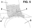
Figure 5 is a perspective view of the cutting device for flexible material according to the present invention, during the cut of the flexible material, with a base that has a different design with regards to the preceding figures. - The cutting device for flexible material, comprises a
blade 1, which may be straight, curved, or with a design to be defined, placed on abase 5 for cutting a sheet offlexible material 4. In order to carry out this cut, either saidblade 1 may move relative to said sheet offlexible material 4, or vice versa, i.e., a sheet offlexible material 4 may move relative to saidblade 1. - As it has been mentioned earlier, in the conventional cutting devices for flexible material it is common that wrinkles are produced in the zone where the
blade 1 is in contact with the sheet offlexible material 4, the cut not being correctly made, instead the sheet offlexible material 4 is torn or ripped, rather tan cut. - In order to solve this drawback, the cutting device according to the present invention, comprises a plurality of
bristles 2 placed above saidbase 5, such that they vertically and horizontally press the sheet offlexible material 4 when the cut of the sheet offlexible material 4 is being carried out. - The pressure exerted by the
bristles 2 onto the sheet offlexible material 4 has been represented infigures 2 and3 by means of corresponding arrows (indicated with FH in order to represent the horizontal or lateral force and Fv in order to represent the vertical force). - Said
elastic bristles 2 form an acute angle with the upper surface of saidbase 5, and said angle is advantageously adjustable to regulate the pressure exerted onto thebase 5. - Said
bristles 2 are elastic, and according to a preferred embodiment, are made of a synthetic or natural material, with a diameter comprised between 0.05 mm and 2.5 mm, for example, 0.7 mm. Moreover, said bristles are variable in length, according to the shape, size and design of the blade, for example, between 3 mm and 500 mm, bearing a relation with the flexible material to be cut, the separation between said bristles being comprised between 0.001 and 5 mm. - In this way, the individual pressure applied by each
bristle 2 onto the sheet offlexible material 4 is very low and distributed (in such a way that the material closer to the blade receives more pressure), however the set ofbristles 2 allows a suitable pressure to be applied so as to hold the sheet of flexible material in order to avoid wrinkles and obtain a clean cut. - Said
bristles 2 are attached to asupport 3 on the end that is not in contact with the sheet offlexible material 4, such that the assembly of saidbristles 2 and saidsupport 3 define an element in the form of a brush. - As can be appreciated in the figures, the upper surface of said
base 5 is preferably curved, although it could have any suitable form. - If desired, at the end of the
bristles 2 that is in contact with the sheet offlexible material 4 during the cut, asphere 6 may be placed, with a diameter slightly larger than the diameter of thebristles 2. - As an alternative, the end of the
bristles 2 that is in contact with the sheet offlexible material 4 during the cut, may be straight.
Claims (9)
- A cutting device for flexible material, which comprises a blade (1), wherein either the blade (1) can move relative to a sheet of flexible material (4) or said sheet of flexible material (4) can move relative to said blade (1), said blade (1) being associated with a plurality of elastic bristles (2), the blade (1) being placed on a base (5) where the flexible material to be cut is supported, characterized in that all of said elastic bristles (2) form an acute angle with the upper surface of said base (5), so that the elastic bristles (2) vertically and horizontally press and stabilize the flexible material against said base (5).
- The cutting device for flexible material according to claim 1, wherein said plurality of elastic bristles (2) are attached to a support (3) on one of the ends thereof.
- The cutting device for flexible material according to claim 1, wherein at least some bristles of said plurality of elastic bristles (2) comprise a sphere (6) at their tip in contact with the sheet of flexible material (4) during the cutting operation.
- The cutting device for flexible material according to claim 1 or 2, wherein said elastic bristles (2) are made of synthetic materials, such as nylon.
- The cutting device for flexible material according to any one of the preceding claims, wherein said elastic bristles (2) have a diameter comprised between 0.05 mm and 2.5 mm.
- The cutting device for flexible material according to any one of the preceding claims, wherein said elastic bristles (2) have a length comprised between 3 mm and 500 mm.
- The cutting device for flexible material according to any one of the preceding claims, wherein the separation between said elastic bristles (2) is comprised between 0.001 mm and 5 mm.
- The cutting device for flexible material according to claim 1, wherein said blade (1) is straight.
- The cutting device for flexible material according to claim 1, wherein said base (5) against which the sheet of flexible material (4) to be cut rests is curved.
Priority Applications (1)
| Application Number | Priority Date | Filing Date | Title |
|---|---|---|---|
| RS20220995A RS63691B1 (en) | 2013-12-05 | 2014-12-05 | Cutting device for flexible material |
Applications Claiming Priority (2)
| Application Number | Priority Date | Filing Date | Title |
|---|---|---|---|
| ES201331785A ES2540377B1 (en) | 2013-12-05 | 2013-12-05 | Cutting device for flexible material |
| PCT/ES2014/070899 WO2015082749A1 (en) | 2013-12-05 | 2014-12-05 | Cutting device for flexible material |
Publications (3)
| Publication Number | Publication Date |
|---|---|
| EP3078464A1 EP3078464A1 (en) | 2016-10-12 |
| EP3078464A4 EP3078464A4 (en) | 2017-08-30 |
| EP3078464B1 true EP3078464B1 (en) | 2022-08-17 |
Family
ID=53272943
Family Applications (1)
| Application Number | Title | Priority Date | Filing Date |
|---|---|---|---|
| EP14867392.4A Active EP3078464B1 (en) | 2013-12-05 | 2014-12-05 | Cutting device for flexible material |
Country Status (7)
| Country | Link |
|---|---|
| US (1) | US10183412B2 (en) |
| EP (1) | EP3078464B1 (en) |
| JP (1) | JP6257116B2 (en) |
| CN (1) | CN106457588B (en) |
| ES (2) | ES2540377B1 (en) |
| RS (1) | RS63691B1 (en) |
| WO (1) | WO2015082749A1 (en) |
Families Citing this family (2)
| Publication number | Priority date | Publication date | Assignee | Title |
|---|---|---|---|---|
| CN110240101A (en) * | 2019-05-08 | 2019-09-17 | 梁馨月 | A kind of Yoghourt strip of paper used for sealing opening device |
| EP3738720A1 (en) * | 2019-05-13 | 2020-11-18 | Open Mind Ventures, S.L.U. | System for handling elements |
Family Cites Families (23)
| Publication number | Priority date | Publication date | Assignee | Title |
|---|---|---|---|---|
| US1782674A (en) * | 1928-06-30 | 1930-11-25 | Hoe & Co R | Web-cutting mechanism |
| US2787427A (en) * | 1953-03-04 | 1957-04-02 | Black Clawson Co | Web winding machine |
| BE548293A (en) * | 1956-05-09 | 1900-01-01 | ||
| US2913926A (en) * | 1957-12-12 | 1959-11-24 | Hammond Machinery Builders Inc | Brush-type guard for printer's saw |
| US3599518A (en) * | 1968-02-16 | 1971-08-17 | Harris Intertype Corp | Paperboard cutting apparatus and method |
| US3618436A (en) * | 1969-08-25 | 1971-11-09 | Donald A Brown | Brush surfaced anvil for rotary sheet-cutting equipment |
| GB1377644A (en) * | 1971-02-05 | 1974-12-18 | Masson Scott Thrissell Eng Ltd | Winding of continuous webs of sheet material |
| US3763748A (en) * | 1972-05-18 | 1973-10-09 | Harris Intertype Corp | Corrugated paperboard slitter |
| US3942781A (en) * | 1974-07-22 | 1976-03-09 | Gerber Garment Technology, Inc. | Penetrable support |
| US4003276A (en) * | 1974-09-30 | 1977-01-18 | Molins Machine Company, Inc. | Slitter and dust collector therefor |
| GB2000439B (en) | 1977-07-01 | 1982-03-17 | Kao Corp | Hair brush |
| US4331051A (en) | 1979-09-10 | 1982-05-25 | Gerber Garment Technology, Inc. | Apparatus for cutting sheet material with variable gain closed loop |
| CH682645A5 (en) * | 1990-02-21 | 1993-10-29 | Peters W Maschf | Splitting machine in a long strip of material that scrolls. |
| CA2102937A1 (en) | 1993-01-07 | 1994-07-08 | Thomas J. Daul | Cutoff and transference mechanism for rewinder |
| DE4310900A1 (en) * | 1993-04-02 | 1994-10-06 | Basf Magnetics Gmbh | Cutting and application device for material webs on winding machines |
| US5816177A (en) | 1995-12-04 | 1998-10-06 | Sew Simple Systems, Inc. | Material feeding, aligning cutting and edge finishing system |
| US5836224A (en) * | 1995-12-27 | 1998-11-17 | Gerber Garment Technology, Inc. | Method and apparatus for working on sheet material |
| US20030079588A1 (en) * | 2001-10-30 | 2003-05-01 | Hamilton Ernest J. | Blade assembly cover |
| US8468921B2 (en) * | 2004-05-26 | 2013-06-25 | Bhs Corrugated Maschinen-Und Anlagenbau Gmbh | Brush cylinder |
| US20080273951A1 (en) | 2007-05-04 | 2008-11-06 | Stein Darryl C | Fixturing Device for Holding Sheet Type Material |
| JP2009072886A (en) * | 2007-09-21 | 2009-04-09 | Shima Seiki Mfg Ltd | Cutter |
| US8544371B2 (en) | 2010-10-04 | 2013-10-01 | Tzu-Che Lin | Paperboard slitter machine |
| CN202825889U (en) * | 2012-08-21 | 2013-03-27 | 王俊峰 | Poria cocos cutting machine |
-
2013
- 2013-12-05 ES ES201331785A patent/ES2540377B1/en active Active
-
2014
- 2014-12-05 EP EP14867392.4A patent/EP3078464B1/en active Active
- 2014-12-05 US US15/102,192 patent/US10183412B2/en active Active
- 2014-12-05 WO PCT/ES2014/070899 patent/WO2015082749A1/en active Application Filing
- 2014-12-05 RS RS20220995A patent/RS63691B1/en unknown
- 2014-12-05 ES ES14867392T patent/ES2927970T3/en active Active
- 2014-12-05 CN CN201480068167.XA patent/CN106457588B/en active Active
- 2014-12-05 JP JP2016557195A patent/JP6257116B2/en not_active Expired - Fee Related
Also Published As
| Publication number | Publication date |
|---|---|
| EP3078464A4 (en) | 2017-08-30 |
| CN106457588A (en) | 2017-02-22 |
| US10183412B2 (en) | 2019-01-22 |
| JP6257116B2 (en) | 2018-01-10 |
| ES2927970T3 (en) | 2022-11-14 |
| ES2540377B1 (en) | 2016-04-21 |
| RS63691B1 (en) | 2022-11-30 |
| WO2015082749A1 (en) | 2015-06-11 |
| CN106457588B (en) | 2019-07-12 |
| JP2016539817A (en) | 2016-12-22 |
| EP3078464A1 (en) | 2016-10-12 |
| ES2540377A1 (en) | 2015-07-09 |
| US20160303751A1 (en) | 2016-10-20 |
Similar Documents
| Publication | Publication Date | Title |
|---|---|---|
| US8707838B2 (en) | Cutting arrangement having a tip-to-tip blade arrangement | |
| CN204780396U (en) | Cutting machine | |
| EP3078464B1 (en) | Cutting device for flexible material | |
| JP4157114B2 (en) | Paper discharger module for printing press | |
| CN106966215B (en) | A kind of corrugated board pile collating unit | |
| US8453547B2 (en) | Method and device for trimming at least one side edge of a bound printed product | |
| US6485012B1 (en) | Adjustable indexing roller mechanism | |
| US20070221033A1 (en) | Cutting Knife for Rotary Cutting Installations | |
| CN209836651U (en) | Non-woven fabric width dividing and cutting machine | |
| US11446940B2 (en) | Cutter assembly with movable trench cover | |
| EP3317054B1 (en) | Device for cutting paper and other graphic substrates wound in rolls | |
| US1741520A (en) | Roll cutting and winding machine | |
| US141487A (en) | Improvement in machines for folding, cutting, and trimming paper | |
| ES2908857T3 (en) | Cross cutting device and method for stabilizing a cutting edge during crush cutting | |
| US859537A (en) | Paper-cutting device for wrapping-machines. | |
| EP2087970B1 (en) | Film cutter | |
| CN201471530U (en) | Gear dotted line perforating device | |
| EP2759502A1 (en) | Recording apparatus | |
| EP2965881A1 (en) | Slitting apparatus and method | |
| US20200331278A1 (en) | Retractable printable medium support | |
| US2240796A (en) | Band trimming or cutting machine | |
| US20090044675A1 (en) | Cutting arrangement having a tip-to-tip blade arrangement | |
| KR20150054385A (en) | Knife for film cutting and film cutter using the same | |
| CN101367211A (en) | Sorting and cutting method and device | |
| CN105538395A (en) | Adjustable cutter bit device of mushroom slicing machine |
Legal Events
| Date | Code | Title | Description |
|---|---|---|---|
| PUAI | Public reference made under article 153(3) epc to a published international application that has entered the european phase |
Free format text: ORIGINAL CODE: 0009012 |
|
| 17P | Request for examination filed |
Effective date: 20160704 |
|
| AK | Designated contracting states |
Kind code of ref document: A1 Designated state(s): AL AT BE BG CH CY CZ DE DK EE ES FI FR GB GR HR HU IE IS IT LI LT LU LV MC MK MT NL NO PL PT RO RS SE SI SK SM TR |
|
| AX | Request for extension of the european patent |
Extension state: BA ME |
|
| DAX | Request for extension of the european patent (deleted) | ||
| A4 | Supplementary search report drawn up and despatched |
Effective date: 20170728 |
|
| RIC1 | Information provided on ipc code assigned before grant |
Ipc: B26D 7/04 20060101ALI20170724BHEP Ipc: B26D 7/01 20060101ALI20170724BHEP Ipc: A46D 1/00 20060101ALI20170724BHEP Ipc: D06H 7/00 20060101ALI20170724BHEP Ipc: B26D 1/04 20060101ALI20170724BHEP Ipc: B26D 1/02 20060101AFI20170724BHEP |
|
| STAA | Information on the status of an ep patent application or granted ep patent |
Free format text: STATUS: EXAMINATION IS IN PROGRESS |
|
| STAA | Information on the status of an ep patent application or granted ep patent |
Free format text: STATUS: EXAMINATION IS IN PROGRESS |
|
| 17Q | First examination report despatched |
Effective date: 20201222 |
|
| STAA | Information on the status of an ep patent application or granted ep patent |
Free format text: STATUS: EXAMINATION IS IN PROGRESS |
|
| GRAP | Despatch of communication of intention to grant a patent |
Free format text: ORIGINAL CODE: EPIDOSNIGR1 |
|
| STAA | Information on the status of an ep patent application or granted ep patent |
Free format text: STATUS: GRANT OF PATENT IS INTENDED |
|
| INTG | Intention to grant announced |
Effective date: 20220603 |
|
| GRAS | Grant fee paid |
Free format text: ORIGINAL CODE: EPIDOSNIGR3 |
|
| GRAA | (expected) grant |
Free format text: ORIGINAL CODE: 0009210 |
|
| STAA | Information on the status of an ep patent application or granted ep patent |
Free format text: STATUS: THE PATENT HAS BEEN GRANTED |
|
| AK | Designated contracting states |
Kind code of ref document: B1 Designated state(s): AL AT BE BG CH CY CZ DE DK EE ES FI FR GB GR HR HU IE IS IT LI LT LU LV MC MK MT NL NO PL PT RO RS SE SI SK SM TR |
|
| REG | Reference to a national code |
Ref country code: CH Ref legal event code: EP |
|
| REG | Reference to a national code |
Ref country code: DE Ref legal event code: R096 Ref document number: 602014084669 Country of ref document: DE |
|
| REG | Reference to a national code |
Ref country code: IE Ref legal event code: FG4D |
|
| REG | Reference to a national code |
Ref country code: AT Ref legal event code: REF Ref document number: 1511883 Country of ref document: AT Kind code of ref document: T Effective date: 20220915 |
|
| REG | Reference to a national code |
Ref country code: RO Ref legal event code: EPE |
|
| REG | Reference to a national code |
Ref country code: ES Ref legal event code: FG2A Ref document number: 2927970 Country of ref document: ES Kind code of ref document: T3 Effective date: 20221114 |
|
| REG | Reference to a national code |
Ref country code: NL Ref legal event code: MP Effective date: 20220817 |
|
| REG | Reference to a national code |
Ref country code: LT Ref legal event code: MG9D |
|
| PG25 | Lapsed in a contracting state [announced via postgrant information from national office to epo] |
Ref country code: SE Free format text: LAPSE BECAUSE OF FAILURE TO SUBMIT A TRANSLATION OF THE DESCRIPTION OR TO PAY THE FEE WITHIN THE PRESCRIBED TIME-LIMIT Effective date: 20220817 Ref country code: PT Free format text: LAPSE BECAUSE OF FAILURE TO SUBMIT A TRANSLATION OF THE DESCRIPTION OR TO PAY THE FEE WITHIN THE PRESCRIBED TIME-LIMIT Effective date: 20221219 Ref country code: NO Free format text: LAPSE BECAUSE OF FAILURE TO SUBMIT A TRANSLATION OF THE DESCRIPTION OR TO PAY THE FEE WITHIN THE PRESCRIBED TIME-LIMIT Effective date: 20221117 Ref country code: NL Free format text: LAPSE BECAUSE OF FAILURE TO SUBMIT A TRANSLATION OF THE DESCRIPTION OR TO PAY THE FEE WITHIN THE PRESCRIBED TIME-LIMIT Effective date: 20220817 Ref country code: LV Free format text: LAPSE BECAUSE OF FAILURE TO SUBMIT A TRANSLATION OF THE DESCRIPTION OR TO PAY THE FEE WITHIN THE PRESCRIBED TIME-LIMIT Effective date: 20220817 Ref country code: LT Free format text: LAPSE BECAUSE OF FAILURE TO SUBMIT A TRANSLATION OF THE DESCRIPTION OR TO PAY THE FEE WITHIN THE PRESCRIBED TIME-LIMIT Effective date: 20220817 Ref country code: FI Free format text: LAPSE BECAUSE OF FAILURE TO SUBMIT A TRANSLATION OF THE DESCRIPTION OR TO PAY THE FEE WITHIN THE PRESCRIBED TIME-LIMIT Effective date: 20220817 |
|
| PGFP | Annual fee paid to national office [announced via postgrant information from national office to epo] |
Ref country code: RS Payment date: 20221124 Year of fee payment: 9 Ref country code: RO Payment date: 20221124 Year of fee payment: 9 |
|
| REG | Reference to a national code |
Ref country code: AT Ref legal event code: MK05 Ref document number: 1511883 Country of ref document: AT Kind code of ref document: T Effective date: 20220817 |
|
| PG25 | Lapsed in a contracting state [announced via postgrant information from national office to epo] |
Ref country code: PL Free format text: LAPSE BECAUSE OF FAILURE TO SUBMIT A TRANSLATION OF THE DESCRIPTION OR TO PAY THE FEE WITHIN THE PRESCRIBED TIME-LIMIT Effective date: 20220817 Ref country code: IS Free format text: LAPSE BECAUSE OF FAILURE TO SUBMIT A TRANSLATION OF THE DESCRIPTION OR TO PAY THE FEE WITHIN THE PRESCRIBED TIME-LIMIT Effective date: 20221217 Ref country code: HR Free format text: LAPSE BECAUSE OF FAILURE TO SUBMIT A TRANSLATION OF THE DESCRIPTION OR TO PAY THE FEE WITHIN THE PRESCRIBED TIME-LIMIT Effective date: 20220817 Ref country code: GR Free format text: LAPSE BECAUSE OF FAILURE TO SUBMIT A TRANSLATION OF THE DESCRIPTION OR TO PAY THE FEE WITHIN THE PRESCRIBED TIME-LIMIT Effective date: 20221118 |
|
| PG25 | Lapsed in a contracting state [announced via postgrant information from national office to epo] |
Ref country code: SM Free format text: LAPSE BECAUSE OF FAILURE TO SUBMIT A TRANSLATION OF THE DESCRIPTION OR TO PAY THE FEE WITHIN THE PRESCRIBED TIME-LIMIT Effective date: 20220817 Ref country code: DK Free format text: LAPSE BECAUSE OF FAILURE TO SUBMIT A TRANSLATION OF THE DESCRIPTION OR TO PAY THE FEE WITHIN THE PRESCRIBED TIME-LIMIT Effective date: 20220817 Ref country code: CZ Free format text: LAPSE BECAUSE OF FAILURE TO SUBMIT A TRANSLATION OF THE DESCRIPTION OR TO PAY THE FEE WITHIN THE PRESCRIBED TIME-LIMIT Effective date: 20220817 Ref country code: AT Free format text: LAPSE BECAUSE OF FAILURE TO SUBMIT A TRANSLATION OF THE DESCRIPTION OR TO PAY THE FEE WITHIN THE PRESCRIBED TIME-LIMIT Effective date: 20220817 |
|
| PGFP | Annual fee paid to national office [announced via postgrant information from national office to epo] |
Ref country code: ES Payment date: 20230111 Year of fee payment: 9 |
|
| REG | Reference to a national code |
Ref country code: DE Ref legal event code: R097 Ref document number: 602014084669 Country of ref document: DE |
|
| PG25 | Lapsed in a contracting state [announced via postgrant information from national office to epo] |
Ref country code: SK Free format text: LAPSE BECAUSE OF FAILURE TO SUBMIT A TRANSLATION OF THE DESCRIPTION OR TO PAY THE FEE WITHIN THE PRESCRIBED TIME-LIMIT Effective date: 20220817 Ref country code: EE Free format text: LAPSE BECAUSE OF FAILURE TO SUBMIT A TRANSLATION OF THE DESCRIPTION OR TO PAY THE FEE WITHIN THE PRESCRIBED TIME-LIMIT Effective date: 20220817 |
|
| P01 | Opt-out of the competence of the unified patent court (upc) registered |
Effective date: 20230328 |
|
| P02 | Opt-out of the competence of the unified patent court (upc) changed |
Effective date: 20230421 |
|
| PLBE | No opposition filed within time limit |
Free format text: ORIGINAL CODE: 0009261 |
|
| STAA | Information on the status of an ep patent application or granted ep patent |
Free format text: STATUS: NO OPPOSITION FILED WITHIN TIME LIMIT |
|
| PG25 | Lapsed in a contracting state [announced via postgrant information from national office to epo] |
Ref country code: AL Free format text: LAPSE BECAUSE OF FAILURE TO SUBMIT A TRANSLATION OF THE DESCRIPTION OR TO PAY THE FEE WITHIN THE PRESCRIBED TIME-LIMIT Effective date: 20220817 |
|
| 26N | No opposition filed |
Effective date: 20230519 |
|
| REG | Reference to a national code |
Ref country code: CH Ref legal event code: PL |
|
| GBPC | Gb: european patent ceased through non-payment of renewal fee |
Effective date: 20221205 |
|
| REG | Reference to a national code |
Ref country code: BE Ref legal event code: MM Effective date: 20221231 |
|
| PG25 | Lapsed in a contracting state [announced via postgrant information from national office to epo] |
Ref country code: SI Free format text: LAPSE BECAUSE OF FAILURE TO SUBMIT A TRANSLATION OF THE DESCRIPTION OR TO PAY THE FEE WITHIN THE PRESCRIBED TIME-LIMIT Effective date: 20220817 Ref country code: LU Free format text: LAPSE BECAUSE OF NON-PAYMENT OF DUE FEES Effective date: 20221205 |
|
| PG25 | Lapsed in a contracting state [announced via postgrant information from national office to epo] |
Ref country code: LI Free format text: LAPSE BECAUSE OF NON-PAYMENT OF DUE FEES Effective date: 20221231 Ref country code: IE Free format text: LAPSE BECAUSE OF NON-PAYMENT OF DUE FEES Effective date: 20221205 Ref country code: GB Free format text: LAPSE BECAUSE OF NON-PAYMENT OF DUE FEES Effective date: 20221205 Ref country code: CH Free format text: LAPSE BECAUSE OF NON-PAYMENT OF DUE FEES Effective date: 20221231 |
|
| PG25 | Lapsed in a contracting state [announced via postgrant information from national office to epo] |
Ref country code: BE Free format text: LAPSE BECAUSE OF NON-PAYMENT OF DUE FEES Effective date: 20221231 |
|
| PGFP | Annual fee paid to national office [announced via postgrant information from national office to epo] |
Ref country code: TR Payment date: 20231204 Year of fee payment: 10 Ref country code: IT Payment date: 20231228 Year of fee payment: 10 Ref country code: FR Payment date: 20231103 Year of fee payment: 10 Ref country code: DE Payment date: 20231214 Year of fee payment: 10 |
|
| PG25 | Lapsed in a contracting state [announced via postgrant information from national office to epo] |
Ref country code: HU Free format text: LAPSE BECAUSE OF FAILURE TO SUBMIT A TRANSLATION OF THE DESCRIPTION OR TO PAY THE FEE WITHIN THE PRESCRIBED TIME-LIMIT; INVALID AB INITIO Effective date: 20141205 |