EP3078408A1 - Filter element with flap and filter system - Google Patents
Filter element with flap and filter system Download PDFInfo
- Publication number
- EP3078408A1 EP3078408A1 EP16162572.8A EP16162572A EP3078408A1 EP 3078408 A1 EP3078408 A1 EP 3078408A1 EP 16162572 A EP16162572 A EP 16162572A EP 3078408 A1 EP3078408 A1 EP 3078408A1
- Authority
- EP
- European Patent Office
- Prior art keywords
- filter
- seal
- tab
- filter element
- sideband
- Prior art date
- Legal status (The legal status is an assumption and is not a legal conclusion. Google has not performed a legal analysis and makes no representation as to the accuracy of the status listed.)
- Granted
Links
Images

Classifications
-
- B—PERFORMING OPERATIONS; TRANSPORTING
- B60—VEHICLES IN GENERAL
- B60H—ARRANGEMENTS OF HEATING, COOLING, VENTILATING OR OTHER AIR-TREATING DEVICES SPECIALLY ADAPTED FOR PASSENGER OR GOODS SPACES OF VEHICLES
- B60H3/00—Other air-treating devices
- B60H3/06—Filtering
- B60H3/0658—Filter elements specially adapted for their arrangement in vehicles
-
- B—PERFORMING OPERATIONS; TRANSPORTING
- B01—PHYSICAL OR CHEMICAL PROCESSES OR APPARATUS IN GENERAL
- B01D—SEPARATION
- B01D46/00—Filters or filtering processes specially modified for separating dispersed particles from gases or vapours
- B01D46/0002—Casings; Housings; Frame constructions
-
- B—PERFORMING OPERATIONS; TRANSPORTING
- B01—PHYSICAL OR CHEMICAL PROCESSES OR APPARATUS IN GENERAL
- B01D—SEPARATION
- B01D46/00—Filters or filtering processes specially modified for separating dispersed particles from gases or vapours
- B01D46/0002—Casings; Housings; Frame constructions
- B01D46/0005—Mounting of filtering elements within casings, housings or frames
-
- B—PERFORMING OPERATIONS; TRANSPORTING
- B01—PHYSICAL OR CHEMICAL PROCESSES OR APPARATUS IN GENERAL
- B01D—SEPARATION
- B01D46/00—Filters or filtering processes specially modified for separating dispersed particles from gases or vapours
- B01D46/10—Particle separators, e.g. dust precipitators, using filter plates, sheets or pads having plane surfaces
- B01D46/12—Particle separators, e.g. dust precipitators, using filter plates, sheets or pads having plane surfaces in multiple arrangements
- B01D46/121—V-type arrangements
-
- B—PERFORMING OPERATIONS; TRANSPORTING
- B01—PHYSICAL OR CHEMICAL PROCESSES OR APPARATUS IN GENERAL
- B01D—SEPARATION
- B01D46/00—Filters or filtering processes specially modified for separating dispersed particles from gases or vapours
- B01D46/52—Particle separators, e.g. dust precipitators, using filters embodying folded corrugated or wound sheet material
- B01D46/521—Particle separators, e.g. dust precipitators, using filters embodying folded corrugated or wound sheet material using folded, pleated material
- B01D46/525—Particle separators, e.g. dust precipitators, using filters embodying folded corrugated or wound sheet material using folded, pleated material which comprises flutes
-
- B—PERFORMING OPERATIONS; TRANSPORTING
- B60—VEHICLES IN GENERAL
- B60H—ARRANGEMENTS OF HEATING, COOLING, VENTILATING OR OTHER AIR-TREATING DEVICES SPECIALLY ADAPTED FOR PASSENGER OR GOODS SPACES OF VEHICLES
- B60H3/00—Other air-treating devices
- B60H3/06—Filtering
- B60H3/0608—Filter arrangements in the air stream
-
- B—PERFORMING OPERATIONS; TRANSPORTING
- B01—PHYSICAL OR CHEMICAL PROCESSES OR APPARATUS IN GENERAL
- B01D—SEPARATION
- B01D2265/00—Casings, housings or mounting for filters specially adapted for separating dispersed particles from gases or vapours
- B01D2265/02—Non-permanent measures for connecting different parts of the filter
- B01D2265/024—Mounting aids
-
- B—PERFORMING OPERATIONS; TRANSPORTING
- B01—PHYSICAL OR CHEMICAL PROCESSES OR APPARATUS IN GENERAL
- B01D—SEPARATION
- B01D2271/00—Sealings for filters specially adapted for separating dispersed particles from gases or vapours
- B01D2271/02—Gaskets, sealings
-
- B—PERFORMING OPERATIONS; TRANSPORTING
- B01—PHYSICAL OR CHEMICAL PROCESSES OR APPARATUS IN GENERAL
- B01D—SEPARATION
- B01D2271/00—Sealings for filters specially adapted for separating dispersed particles from gases or vapours
- B01D2271/02—Gaskets, sealings
- B01D2271/027—Radial sealings
-
- B—PERFORMING OPERATIONS; TRANSPORTING
- B01—PHYSICAL OR CHEMICAL PROCESSES OR APPARATUS IN GENERAL
- B01D—SEPARATION
- B01D2279/00—Filters adapted for separating dispersed particles from gases or vapours specially modified for specific uses
- B01D2279/40—Filters adapted for separating dispersed particles from gases or vapours specially modified for specific uses for cleaning of environmental air, e.g. by filters installed on vehicles or on streets
Definitions
- the invention relates to a filter element for filtering a fluid with a tab and a filter system, in particular for use as an air filter, in particular for cabin air filtration, in particular of a vehicle.
- a filter element which is used, for example, as a motor vehicle interior air filter or filter element for a motor vehicle air conditioning system, serves to filter the outside of the interior of the vehicle conducted and conditioned air.
- particle or odor filters are used or combinations thereof, which filter out the particles contained in the air and inherent odors from the ambient air.
- the effectiveness of a filter or of such a filter system also depends on the fact that the filter system is mounted in the correct position in the filter housing or an associated filter receptacle of the filter housing.
- a filter arrangement for filtering the supply air of a motor vehicle engine in which projecting tabs on the opposite longitudinal sides and are pivotally articulated on the filter medium.
- the filter element is locked in the upper part of a filter housing on the clean air side so that the tabs are applied sealingly on the housing walls.
- the free ends of the tabs show against the flow direction of the air. From the inflow side incoming air can therefore pivot the movable tabs about the fixed end and press with the free ends against the housing walls.
- tabs are used made of nonwoven fabric.
- the tabs made of nonwoven material furthermore provide a filter medium which additionally filters the supply air to the motor vehicle engine.
- An object of the invention is to provide a filter element for filtering a fluid, in particular for air filtering, in particular for cabin air filtration, which allows to reliably insert the filter element tightly into a filter housing.
- Another object is to provide a filter system for filtering a fluid for receiving such a replaceable filter element, which allows to reliably insert the filter element tightly into a filter housing.
- a filter element for filtering a fluid comprising at least one, in particular flat, filter bellows of a particular zigzag folded filter medium with a designated raw side and one of these opposite intended clean side, wherein the filter bellows surrounding End faces surrounding a surface applied sideband is arranged on the outside of a circumferential seal is arranged.
- the side band on a projecting beyond the clean side of the filter bellows tab, which tab on the front sides V-shaped in particular folded back on a folding edge on the seal can be arranged.
- the further object is achieved by a filter system which is provided for receiving such a filter element.
- a filter element for filtering a fluid in particular for air filtering, in particular for cabin air filtration, in particular a vehicle proposed, comprising at least one, in particular flat, in particular zigzag folded filter bellows from a filter medium with a designated raw side and one of these opposite intended clean side, wherein on the filter bellows surrounding end faces in particular completely encircling and in particular tightly connected to the filter bellows a surface applied sideband is arranged.
- On an outer side of the side band in particular a completely circumferential seal is arranged.
- the sideband on the clean side of the filter bellows protruding tab on which tab on the front sides V-shaped folded back over the seal can be arranged.
- a part of the lateral sealing of the filter bellows in particular in a zigzag-folded filter medium arranged sidebands, which projects beyond a lower edge of the filter bellows, which limits the clean side, folded back and so protrudes V-shaped to the attached at the end side sideband projecting , partially, in particular only partially on the seal or its outer surface.
- the seal or its outer surface is partially surmounted transversely to the direction of rotation of the seal.
- the tab preferably covers the seal or its outer surface in such a way that a region of an outer surface of the seal which faces away from the sideband and which is in particular completely parallel to the V-shaped tab remains free, and thus continues to seal against a Filter housing can be applied.
- this V-shaped tab When inserted into a filter housing, this V-shaped tab is pressed against the seal and at least partially, in particular in the region of the overlap between the V-tab and seal between seal and filter housing clamped so that the tab is thus firmly fixed to the filter housing and / or rests.
- the seal which may for example be formed from sponge rubber and may be designed as a rectangular profile, is conveniently glued to the sideband.
- the seal may have an adhesive layer, with which the seal may be glued to the sideband.
- the seal can also be applied directly as a sealant bead on the sideband.
- the tab with the seal comes when inserting the filter element into the filter housing preferably first the V-tab to rest on the housing, for example, at the edge of a housing-side sealing surface or on the housing-side sealing surface.
- the gasket is further pre-compressed and compression achieved upon insertion of the filter element into the filter housing without detachment of the gasket. The compression takes place such that the outer surface of the seal is moved in the direction of the sideband. Since this is perpendicular to the direction of flow and installation direction, this is also referred to as a radial seal or radially adjacent seal.
- the V-shaped tab When inserted into a filter housing, the V-shaped tab is in particular pressed against the seal such that the V-shaped tab forms an insertion bevel, which reduces the risk of shearing the seal when inserted into a filter housing.
- the V-tab preferably experiences a force in the direction of the seal, whereby the seal in the region in which the V-tab is applied to this, is slightly pre-compressed.
- the filter element with the seal can be installed more easily in a direction normal to the intended clean side or raw side into a filter housing, in particular if the seal in the unpressed state has a greater extent than the installation opening.
- the tab acts as a supportive insertion aid when inserting the filter element into the filter housing.
- the cross-sectional area of the filter element can be conveniently increased, since the seal can be pressed easier and more effective and thus the coverage can be increased with a mounting dimension of the filter housing can.
- the filtration properties can be improved, for example by increasing the service life and / or a reduction in the flow velocity of the fluid with increasing the filter surface.
- the solution according to the invention of a tab which lies folded back in a V-shape at least partially over the seal, can be used on flat filter elements for air filtering, in particular for cabin air filtering, in which radial compressible seals are used.
- the tab can at least partially cover the seal on an outer side facing away from the side band in particular. This ensures that when inserting the filter element in a filter housing, the tab between the seal and the wall of the filter housing is clamped and thus facilitates both the insertion of the filter element by a pre-compression of the seal and an additional sealing effect can be done via the tab. Also, the filter element can more easily slide into the filter housing, so that the risk that the seal separates from the sideband, is reduced.
- the V-shaped tab covers only the part of an outer surface of the seal, which faces away from a side band, in particular, which is closer to a folding or bending edge on which the V-shaped tab is folded.
- This region of the outer surface of the seal closer to the folding or bending edge is preferably in each case a strip which is covered by the V lugs and in particular continuous strips.
- the folding or bending edge facing away from the outer surface of the seal is thus available as a sealing surface for sealing against a filter housing.
- This region of the outer surface of the seal facing away from the folding or bending edge is preferably in each case a sealing strip extending along the V-flaps, in particular continuous, running along the covered strip.
- the two strips each preferably have a width of at least 20%, preferably at least 30% of the width of the outer surface of the seal and are particularly preferably each the same width. Since the V-lugs do not cover the seal in the corner regions of the filter element, the full width (in particular of the outer surface) of the seal is available there as a sealing surface for sealing against a filter housing. In this area is often also the cross section of Gasket already slightly pre-formed by the seal is placed around the corner. Therefore, and also due to the small extent of these areas, it is harmless if the V-flaps at these corner positions offer no insertion ramp and can not produce pre-compression.
- the tab may be formed at least to one of the clean side facing edge of the seal heranvrad. This ensures that the tab when inserting the filter element in the filter housing fully covers at least the area up to the seal and so an additional filter effect and sealing is provided by the tab. Also, the filter element can be more easily inserted into the filter housing, so that the risk that the seal separates from the sideband is reduced.
- the tab may be formed with her free end at most to below below the raw side facing edge of the seal heranvrad. This ensures that the tab does not protrude beyond the seal, whereby the concerns of the seal on the wall of the filter housing and the presence of a reliable sealing effect would not be ensured.
- the tab is at least partially withdrawn when inserted into the filter housing, thus exposing a portion of the seal.
- the filter medium can be folded in a zigzag fashion along fold edges, which each extend between opposite end edges of the filter bellows, and each have mutually parallel front edge surfaces on the opposite end faces and end faces on the transverse end faces.
- the filter bellows can be sealed at the end edge surfaces and end faces with the side band.
- sidebands are used to seal the end edge surfaces and faces. Therefore, it is particularly advantageous to provide this sideband with a protruding tab, which can serve to introduce the filter element so easier in a filter housing and seal reliably.
- such folded filter media are particularly favored for applying the inventive solution with V-shaped tab as insertion aid and additional sealing possibility.
- the sidebands usually form the side surfaces of a particular straight, for example, 4-sided, preferably rectangular prism.
- Whose base surfaces are preferably defined by the flow-through surfaces, in particular the clean and raw side, in particular each defined by the folding edges of the filter medium.
- the height of this prism is determined by the width of the sidebands (without V-tab), which is usually constantly circulating.
- a sideband and a V-tab is provided on each side of the prism, d. H. in the case of a 4-sided (eg rectangular prism) 4 V tabs are provided.
- the seal may have a rectangular cross-section. Seals with a rectangular profile are particularly suitable for the use of flat filter elements, since the full width of the seal is used as a sealing surface. Also, the tab can be clamped in a seal with rectangular cross-section even with slight overlap of the tab with the seal upon insertion of the filter element in the filter housing between the wall of the filter housing and the seal and thus effectively develop the effect as an insertion aid and as additional sealing support.
- the outer surface of the seal which acts as a sealing surface and faces away from the sideband, is preferably aligned essentially parallel to the outer surface of the sideband.
- the outer surface is at least over its entire width spaced from the side band, in particular substantially constantly spaced, such that no immediate approach or a transition to the surface of the sideband, for example in the form of a wedge o.
- the seal does not cover the entire width of the sideband. Rather, it is preferred that the gasket so removed from the bending edge of the V-tab the side band is arranged so that the V-tab forms an acute angle when it is folded and rests on the outer surface of the seal.
- the distance of the seal from the bending edge is at least as great as the thickness of the seal, d. H. such as the distance of the outer surface of the seal from the sideband.
- the distance of the seal from the bending edge on the sideband at most 4 or 2 times, and more preferably at most 2 times as large as the thickness of the seal to make the angle between the V-tab and sideband not too acute and to a sufficient To ensure compression of the seal and / or to prevent excessive bending of the V-strap during installation.
- a ratio of 1: 1 to 2: 1 has proven to be optimal from distance to thickness, so that in the unstressed state and on the seal of the adjoining V-strap between V-strap and sideband, acute angles between about 30 ° and about 45 ° are formed.
- a portion of the sideband is also preferably provided, which is exposed, d. H. is not covered by the seal and also preferably just as large and more preferably at least twice as large as the width and / or thickness of the seal.
- the seal be closer to the clean side, i. H. closer to the bending edge of the V-strap. This means that preferably the distance of the seal from the upstream edge of the side band is greater than the distance from the downstream (pure side) edge, d. H. the bending edge.
- the distance of the seal from the upstream edge of the sideband is preferably 50% and particularly preferably 100% greater than the distance from the downstream edge.
- the width of the seal should be at most 50%, more preferably at most 30%, of the width of the sideband. More preferably, the height of the unstressed (relaxed) seal at most 50%, preferably at most 30%, more preferably at most 25% of the width of the sideband.
- the side band to form the tab on a circumference of the clean side circumferentially cut or formed punched By cutting or punching the sideband, a reliable bending edge can be created, so that the tab can be folded back very defined by folding over the protruding sideband V-shaped. Especially with a firmer fleece as a sideband so a targeted vulnerability can be represented favorably for forming a defined tab.
- the seal may comprise sponge rubber or cellular rubber. These materials are particularly favorable when used as sealing materials and therefore also in wide use. Also, the materials have the necessary elasticity to ensure a reliable seal with a suitable coverage of the cross section of the seal with a mounting dimension of the filter housing.
- a seal is formed from a preferably rectangular continuous profile, which is cut to length and preferably parallel to the edges of the sideband formed into a closed ring circumferentially applied to the sidebands, so that the filter medium and the sidebands is completely surrounded circumferentially.
- the seal for the intended installation in a filter housing for an overlap of greater than 10%, preferably greater than 20% of the thickness of the seal may be designed with a mounting dimension of the filter housing.
- Such overlap ensures a reliable sealing effect when pressing the seal when installed in a filter housing, in particular with the support of a V-shaped folded back flap sure.
- the side band and the flap may comprise a nonwoven.
- a nonwoven or a similar textile material can be suitably used as a sideband and thus also as a tab, since such materials have the advantage to be easy to process and to be suitable in addition to the lateral sealing of the filter element.
- the invention relates to a filter system for filtering a fluid with a filter element, wherein the filter element is arranged interchangeably in a filter housing of the filter system and which filter element provides a filter bellows, which has a surface applied sideband at the end faces.
- a circumferential seal is arranged on an outer side of the sideband.
- protruding tab of the side band is at least on the end faces V-shaped folded back over the seal arranged.
- a filter system according to the invention is a part of the lateral sealing of the filter bellows, in particular in a zigzag folded filter medium arranged sidebands, which projects beyond a lower edge of the filter bellows, which limits the clean side, folded back and so protrudes V-shaped to the Front side mounted sideband protruding, partially over the seal.
- this V-shaped tab When inserted into the filter housing, this V-shaped tab is pressed against the seal and at least partially clamped between the seal and filter housing, so that the tab is thus firmly fixed to the filter housing.
- the combination of the V-shaped folded back tab and the seal sealing of the filter element when installed in the filter housing is effected by both the tab and the seal. In this way, a simplified insertion of the filter element in the filter housing is possible, whereby the force required to insert the filter element is reduced in the filter housing.
- the tab in the installed state of the filter element, at least partially cover the seal on an outer side. This ensures that when inserting the filter element in a filter housing, the tab between the seal and the wall of the filter housing is clamped and thus facilitates both the insertion of the filter element by a pre-compression of the seal and an additional sealing effect can be done via the tab. Also, the filter element can more easily slide into the filter housing, so that the risk that the seal separates from the sideband, is reduced.
- the tab may be at least partially disposed between the seal and a housing wall of the filter housing in the installed state of the filter element.
- the tab is clamped between the wall of the filter housing and the seal, so that it is guaranteed in any case that the tab additionally supports the sealing effect of the seal and also the seal during insertion of the filter element into the filter housing from the sideband, on which the seal is glued or foamed, can solve.
- the tab can be arranged in the installed state to the end sides at an acute angle, preferably less than 45 °.
- Such a geometric arrangement favors the insertion process of the filter element in the filter housing.
- the force required for insertion, which must be exerted on the filter element reduced. This also reduces the risk that the seal when inserting the filter element in the filter housing can be detached from the sideband.
- the invention relates to a use of the filter system for air filtering, in particular for cabin air filtration, in particular of a vehicle.
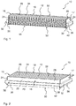
- FIG. 1 shows a longitudinal section through a filter element 10 for filtering a fluid, in particular for air filtering, preferably for cabin air filtration, in particular a vehicle, with a zigzag folded filter medium 14 and a V-shaped folded back flap 36 according to an embodiment of the invention in an isometric view.
- the filter element 10 comprises a flat filter bellows 12 made of a filter medium 14 with a designated raw side 52 and one of these opposite intended clean side 50.
- At the filter bellows 12 surrounding end faces 16, 17, 18, 19 is circumferentially applied sideband 28 is arranged.
- On the outside of the side band 28, a circumferential seal 32 is arranged.
- the side strip 28 has a projecting beyond the clean side 50 of the filter bellows 12 Tab 36, which tab 36 on the end faces 16, 17, 18, 19 V-shaped folded back over the seal 32 is arranged.
- the filter medium 14 is folded in a zigzag shape along folding edges 26 into folds 34 which each extend between opposite end edges 22 of the filter bellows 12.
- the filter medium 14 has in each case on the opposite end faces 18, 19 mutually parallel end edge surfaces 20.
- the seal 32 has a rectangular cross-section, and usually comprises sponge rubber or cellular rubber, which has proved to be a particularly favorable sealing material with suitable elastic properties.
- the tab 36 covers the seal 32 on the outside slightly, since the tab 36 is formed up to the pure side 50 facing edge 38 of the seal 32 zoom.
- the tab 36 could be formed with her free end 37 to below below the raw side 52 facing edge 39 of the seal 32 heranvrad.
- the sideband 28 is expediently recessed or punched to form the tab 36 on a circumference 42 of the clean side 50, in order to be able to reliably fold back the tab.
- the side band 28 and the tab 36 comprise a non-woven fabric or a similar textile fabric, since these materials seal well and can be processed easily.
- FIG. 2 shows the whole filter element 10 after FIG. 1 in isometric view.
- the filter element 10 is circumferentially sealed with the sideband 28. Also circumferentially outside of the sideband 28 arranged with rectangular cross-section seal arranged, for example glued.
- the tab 36 formed as a projection of the side strip 28 on the clean side 50 of the filter element 10 is folded back in the direction of the raw side 52 to over the clean side edge 38 of the seal 32 on all end sides 16, 17, 18, 19 V-shaped.
- the sidebands 28 form the side surfaces of a straight, in this case 4-sided, rectangular prism.
- Its base surfaces are preferably defined by the surfaces through which flows, in particular the clean side 50 and raw side 52, in particular each defined by the folding edges of the filter medium 14.
- the height of this prism is determined by the width of the sidebands 25 (without V-tab), which is preferably circumferentially constant.
- a side band 28 and a tab 36 is provided, ie there are 4 tabs 36 are provided so that all around einbauerfugernde effect can be achieved.
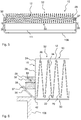
- FIG. 3 is the filter element 10 after FIG. 1 shown when inserted into a filter housing 108.
- the filter element 10 can be inserted by lowering from above into a lower part of the filter housing 108.
- the tab 36 applies to the seal 32, so that the tab 36 facilitates the insertion of the filter element 10 into the filter housing 108 by reducing the necessary insertion force.
- by clamping the tab 36 between the wall of the filter housing 108 and seal 32 favors an additional sealing effect.
- FIG. 4 shows the insertion of the filter element 10 into a filter housing 108 FIG. 3
- the filter element 10 is guided directly over the opening of the lower part of the filter housing 108 and is then further lowered for further insertion into the filter housing 108.
- the seal 32 for the intended installation in the filter housing 108 expediently for an overlap of greater than 10%, preferably greater than 20% of the thickness 44 of the seal 32 with a mounting dimension 110, the clear width of the filter housing 108th corresponds, is designed.
- the tab 36 applies to the wall of the filter housing 108 between seal 32 and wall.
- the seal 32 is compressed upon insertion of the filter element 10, so as to deploy together with the tab 36, the full sealing effect.
- FIG. 5 is the insertion of the filter element 10 into the filter housing 108 after FIG. 3 in a longitudinal section, ie in the other dimension shown. Again, the overlap of the seal 32 in the non-compressed state with the mounting dimension 111 can be seen in this dimension, whereby an effective and reliable sealing of the filter element 10 is achieved against the filter housing 108.
- FIG. 6 shows a detail from the FIG. 5 with focus on the seal 32 and the tab 36.
- the filter bellows 12 is cut parallel to the end edge surface 20 of the end edges 22 with the raised folds 34 of the filter medium 14, which represent the unfolded side 26 respectively the raw side 52 and the clean side 50.
- the filter bellows on the end face 16 with the end face 24 from. All around the filter bellows 12 is completed with the sideband 28 and sealed.
- the seal 32 which is designed with a rectangular cross-section having a thickness 44, adhered to the sideband 28.
- the sideband 28 is expediently recessed or stamped to form the tab 36 on a circumference 42 of the clean side 50, so as to be able to reliably fold back the tab 36.
- the distance of the seal 32 from the bending edge corresponds approximately to the thickness 44 of the seal 32, so that when folding back the tab 36, an acute angle of at most 45 ° to the outside 28 of the sideband 28 can be formed.
- the angle during installation by the compression of the seal 32 sharpener.
- the tab 36 is in the embodiment in FIG. 6 made with the free end 37 of the tab 36 to the clean-side edge 38 of the seal 32 heranvrad.
- the tab 36 can also be designed to reach the raw-side edge 39 of the seal 32.
- the tab 36 is first pressed in the direction of the filter element 10.
- the seal 32 is co-compressed, so that the filter element 10 with tab 36 and seal 32 can slide into the opening of the filter housing 108 and can take a tight sealed seat there.
- the seal 32 is formed in the embodiment shown as well as preferably from a rectangular endless profile, which is cut to length and preferably parallel to the edges of the sideband 28 formed into a closed ring circumferentially on the sidebands 28, so that the filter medium 14 and the sidebands 28th surrounded completely.
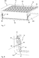
- FIG. 7 shows the filter system 100 according to an embodiment of the invention, which is provided for air filtering, in particular for cabin air filtration, in particular of a vehicle, with inserted into the lower part of the filter housing 108 filter element 10.
- the filter element 10 is thus arranged interchangeably in the filter housing 108 of the filter system.
- the filter element 10 provides the filter bellows 12, which has the surface applied sideband 28 at the end faces 16, 17, 18, 19.
- the circumferential seal 32 is arranged on the outside of the side band 28, the circumferential seal 32 is arranged.
- the over the clean side 50 of the filter bellows 12 projecting tab 36 of the side band 28 is folded back on the end faces 16, 17, 18, 19 disposed over the seal 32.
- the seal 32 on the outside at least partially.
- the tab 36 is so arranged in the installed state of the filter element 10 at least partially between seal 32 and a housing wall 112 of the filter housing 108 and so can provide an additional sealing effect by additionally pressing the seal 32 and pinching the tab 36 between the wall of the filter housing 108 and the seal 32 exercise.
- FIG. 8 is a detail from the FIG. 7 with focus on the seal 32 and the tab 36 shown.
- the tab 36 also partially covers the seal 32 when it is installed by clamping the tab 36 between the wall of the filter housing 108 and the seal 32.
- the tab 36 is in the installed state to the end faces 16, 17, 18, 19 of the filter element 10 at an acute angle 40, preferably less than 45 °, is arranged.
- the arrangement of the tab 36 at an acute angle 40 favors the function of an insertion aid of the tab 36, since in this way the filter element 10 can be introduced into the filter housing 108 with reduced force.
Abstract
Die Erfindung betrifft ein Filterelement (10) zum Filtern eines Fluids. Das Filterelement (10) umfasst wenigstens einen, insbesondere flachen, Filterbalg (12) aus einem Filtermedium (14) mit einer bestimmungsgemäßen Rohseite (52) und einer dieser gegenüberliegenden bestimmungsgemäßen Reinseite (50). An den Filterbalg (12) umgebenden Stirnseiten (16, 17, 18, 19) ist umlaufend ein flächig aufgebrachtes Seitenband (28) angeordnet. An einer Außenseite des Seitenbandes (28) ist eine umlaufende Dichtung (32) angeordnet. Das Seitenband (28) weist eine über die Reinseite (50) des Filterbalgs (12) überstehende Lasche (36) auf, welche Lasche (36) an den Stirnseiten (16, 17, 18, 19) V-förmig zurückgeklappt über der Dichtung (32) anordenbar ist. Die Erfindung betrifft ferner ein Filtersystem (100) mit einem solchen auswechselbaren Filterelement (10) sowie eine Verwendung des Filtersystems (100) zur Luftfilterung, insbesondere zur Innenraumluftfilterung, insbesondere eines Fahrzeugs.The invention relates to a filter element (10) for filtering a fluid. The filter element (10) comprises at least one, in particular flat, filter bellows (12) comprising a filter medium (14) with a designated raw side (52) and a clean side (50) opposite this intended. On the filter bellows (12) surrounding end faces (16, 17, 18, 19) is circumferentially arranged a flat applied sideband (28). On an outer side of the side band (28), a circumferential seal (32) is arranged. The sideband (28) has a tab (36) projecting beyond the clean side (50) of the filter bellows (12), which tab (36) on the end faces (16, 17, 18, 19) folded back in a V-shape over the seal (FIG. 32) can be arranged. The invention further relates to a filter system (100) with such a replaceable filter element (10) and a use of the filter system (100) for air filtering, in particular for cabin air filtration, in particular of a vehicle.
Description
Die Erfindung betrifft ein Filterelement zum Filtern eines Fluids mit Lasche sowie ein Filtersystem, insbesondere zur Verwendung als Luftfilter, insbesondere zur Innenraumluftfilterung, insbesondere eines Fahrzeugs.The invention relates to a filter element for filtering a fluid with a tab and a filter system, in particular for use as an air filter, in particular for cabin air filtration, in particular of a vehicle.
Ein Filterelement, das beispielsweise als Kfz-Innenraum-Luftfilter bzw. Filterelement für eine Kraftfahrzeugklimaanlage eingesetzt wird, dient dazu, die von außen in den Innenraum des Fahrzeugs geleitete und aufbereitete Luft zu filtern. Dabei kommen beispielsweise Partikel- oder Geruchsfilter zum Einsatz oder Kombinationen davon, welche die in der Luft enthaltenen Partikel und inhärenten Gerüche aus der Umgebungsluft herausfiltern. Dabei hängt die Wirksamkeit eines Filters bzw. eines solchen Filtersystems auch davon ab, dass das Filtersystem in der richtigen Position in dem Filtergehäuse bzw. einer zugeordneten Filteraufnahme des Filtergehäuses montiert wird.A filter element, which is used, for example, as a motor vehicle interior air filter or filter element for a motor vehicle air conditioning system, serves to filter the outside of the interior of the vehicle conducted and conditioned air. In this case, for example, particle or odor filters are used or combinations thereof, which filter out the particles contained in the air and inherent odors from the ambient air. The effectiveness of a filter or of such a filter system also depends on the fact that the filter system is mounted in the correct position in the filter housing or an associated filter receptacle of the filter housing.
Aus der
Eine Aufgabe der Erfindung ist es, ein Filterelement zum Filtern eines Fluids, insbesondere zur Luftfilterung, insbesondere zur Innenraumluftfilterung, zu schaffen, das es erlaubt, das Filterelement zuverlässig dicht in ein Filtergehäuse einzusetzen.An object of the invention is to provide a filter element for filtering a fluid, in particular for air filtering, in particular for cabin air filtration, which allows to reliably insert the filter element tightly into a filter housing.
Eine weitere Aufgabe ist es, ein Filtersystem zum Filtern eines Fluids zur Aufnahme eines solchen austauschbaren Filterelements zu schaffen, das es erlaubt, das Filterelement zuverlässig dicht in ein Filtergehäuse einzusetzen.Another object is to provide a filter system for filtering a fluid for receiving such a replaceable filter element, which allows to reliably insert the filter element tightly into a filter housing.
Die vorgenannte Aufgabe wird nach einem Aspekt der Erfindung gelöst von einem Filterelement zum Filtern eines Fluids, das wenigstens einen, insbesondere flachen, Filterbalg aus einem insbesondere zickzackförmig gefalteten Filtermedium mit einer bestimmungsgemäßen Rohseite und einer dieser gegenüberliegenden bestimmungsgemäßen Reinseite, umfasst, wobei an den Filterbalg umgebenden Stirnseiten umlaufend ein flächig aufgebrachtes Seitenband angeordnet ist, auf dessen Außenseite eine umlaufende Dichtung angeordnet ist. Dabei weist das Seitenband eine über die Reinseite des Filterbalgs überstehende Lasche auf, welche Lasche an den Stirnseiten V-förmig insbesondere an einer Klappkante zurückgeklappt über der Dichtung anordenbar ist.The above object is achieved according to one aspect of the invention by a filter element for filtering a fluid comprising at least one, in particular flat, filter bellows of a particular zigzag folded filter medium with a designated raw side and one of these opposite intended clean side, wherein the filter bellows surrounding End faces surrounding a surface applied sideband is arranged on the outside of a circumferential seal is arranged. In this case, the side band on a projecting beyond the clean side of the filter bellows tab, which tab on the front sides V-shaped in particular folded back on a folding edge on the seal can be arranged.
Nach einem anderen Aspekt der Erfindung wird die weitere Aufgabe durch ein Filtersystem gelöst, das zur Aufnahme eines solchen Filterelements vorgesehen ist.According to another aspect of the invention, the further object is achieved by a filter system which is provided for receiving such a filter element.
Günstige Ausgestaltungen und Vorteile der Erfindung ergeben sich aus den weiteren Ansprüchen, der Beschreibung und der Zeichnung.Favorable embodiments and advantages of the invention will become apparent from the other claims, the description and the drawings.
Es wird ein Filterelement zum Filtern eines Fluids, insbesondere zur Luftfilterung, insbesondere zur Innenraumluftfilterung, insbesondere eines Fahrzeugs, vorgeschlagen, das wenigstens einen, insbesondere flachen, insbesondere zickzackförmig gefalteten Filterbalg aus einem Filtermedium mit einer bestimmungsgemäßen Rohseite und einer dieser gegenüberliegenden bestimmungsgemäßen Reinseite umfasst, wobei an den Filterbalg umgebenden Stirnseiten insbesondere vollständig umlaufend und insbesondere dicht mit dem Filterbalg verbunden ein flächig aufgebrachtes Seitenband angeordnet ist. An einer Außenseite des Seitenbandes ist eine insbesondere vollständig umlaufende Dichtung angeordnet. Dabei weist das Seitenband eine über die Reinseite des Filterbalgs überstehende Lasche auf, welche Lasche an den Stirnseiten V-förmig zurückgeklappt über der Dichtung anordenbar ist.It is a filter element for filtering a fluid, in particular for air filtering, in particular for cabin air filtration, in particular a vehicle proposed, comprising at least one, in particular flat, in particular zigzag folded filter bellows from a filter medium with a designated raw side and one of these opposite intended clean side, wherein on the filter bellows surrounding end faces in particular completely encircling and in particular tightly connected to the filter bellows a surface applied sideband is arranged. On an outer side of the side band, in particular a completely circumferential seal is arranged. In this case, the sideband on the clean side of the filter bellows protruding tab on which tab on the front sides V-shaped folded back over the seal can be arranged.
Erfindungsgemäß wird ein Teil des zur seitlichen Abdichtung des Filterbalgs, insbesondere bei einem zickzackförmig gefalteten Filtermedium, angeordneten Seitenbands, der über eine untere Kante des Filterbalgs, der die Reinseite begrenzt, übersteht, zurückgeklappt und ragt so V-förmig zum an den Stirnseiten angebrachten Seitenband abstehend, teilweise, insbesondere nur teilweise über die Dichtung bzw. deren Außenfläche. Teilweise ist hier insbesondere so zu verstehen, dass die Dichtung bzw. deren Außenfläche quer zur Umlaufrichtung der Dichtung teilweise überragt wird. Die Lasche überdeckt die Dichtung bzw. deren Außenfläche bevorzugt derart, dass ein insbesondere vollständig umlaufender, nicht von der V-förmigen Lasche überdeckter Bereich einer insbesondere von dem Seitenband abgewandten, insbesondere parallel zu diesem angeordneten Außenfläche der Dichtung frei bleibt und somit weiterhin dichtend an einem Filtergehäuse anlegbar ist. Beim Einführen in ein Filtergehäuse wird diese V-förmige Lasche an die Dichtung angepresst und zumindest teilweise, insbesondere im Bereich der Überdeckung zwischen V-Lasche und Dichtung zwischen Dichtung und Filtergehäuse eingeklemmt, sodass die Lasche damit am Filtergehäuse fest fixiert ist und/oder anliegt. Insbesondere in eingebautem Zustand wird damit bei der Kombination aus der V-förmig zurückgeklappten Lasche und der Dichtung eine Abdichtung des Filterelements bei Einbau in ein Filtergehäuse sowohl von der Lasche als auch von der Dichtung bewirkt, da der nicht von der V-Lasche überdeckte Bereich einer Außenfläche der Dichtung weiterhin dichtend an einem Filtergehäuse anlegbar ist. Auf diese Weise ist ein vereinfachter Einschub des Filterelementes in ein Filtergehäuse möglich, wodurch insbesondere der Kraftaufwand zum Einführen des Filterelements in das Filtergehäuse reduziert wird.According to the invention, a part of the lateral sealing of the filter bellows, in particular in a zigzag-folded filter medium arranged sidebands, which projects beyond a lower edge of the filter bellows, which limits the clean side, folded back and so protrudes V-shaped to the attached at the end side sideband projecting , partially, in particular only partially on the seal or its outer surface. In some cases, in particular, it should be understood that the seal or its outer surface is partially surmounted transversely to the direction of rotation of the seal. The tab preferably covers the seal or its outer surface in such a way that a region of an outer surface of the seal which faces away from the sideband and which is in particular completely parallel to the V-shaped tab remains free, and thus continues to seal against a Filter housing can be applied. When inserted into a filter housing, this V-shaped tab is pressed against the seal and at least partially, in particular in the region of the overlap between the V-tab and seal between seal and filter housing clamped so that the tab is thus firmly fixed to the filter housing and / or rests. In particular, when installed, it is thus effected in the combination of the V-shaped folded back flap and the seal sealing of the filter element when installed in a filter housing from both the tab and the seal, as the not covered by the V-flap portion of a Outer surface of the seal continues to be sealingly applied to a filter housing. In this way, a simplified insertion of the filter element in a filter housing is possible, whereby in particular the force required to insert the filter element is reduced in the filter housing.
Die Dichtung, die beispielsweise aus Moosgummi ausgebildet sein kann und als Rechteckprofil ausgeführt sein kann, wird zweckmäßigerweise auf das Seitenband aufgeklebt. Dafür kann die Dichtung eine Klebeschicht aufweisen, mit der die Dichtung auf das Seitenband aufgeklebt sein kann. Alternativ kann die Dichtung auch direkt als Dichtmittelraupe auf das Seitenband aufgebracht werden. Da der Querschnitt (Breite/Länge) des Filterelementes günstigerweise größer als der Querschnitt des Filtergehäuses gewählt wird, entsteht eine Überdeckung und die Dichtung wird beim Einsetzen des Filterelements in das Filtergehäuse verpresst. Dadurch könnte sich die Dichtung vom Seitenband lösen und undicht werden. Durch das Überlappen der Lasche mit der Dichtung kommt beim Einführen des Filterelementes in das Filtergehäuse bevorzugt zunächst die V-Lasche zur Anlage am Gehäuse, beispielsweise am Rand einer gehäuseseitigen Dichtfläche oder auf der gehäuseseitigen Dichtfläche. Durch das Überlappen der Lasche mit der Dichtung wird ferner die Dichtung vorverpresst und die Kompression beim Einsetzen des Filterelements in das Filtergehäuse ohne Ablösen der Dichtung erreicht. Die Verpressung erfolgt derart, dass die Außenfläche der Dichtung in Richtung des Seitenbandes bewegt wird. Da dies senkrecht zur Durchströmungsrichtung und Einbaurichtung erfolgt, spricht man hierbei auch von einer Radialdichtung oder radial anliegenden Dichtung. Beim Einführen in ein Filtergehäuse wird die V-förmige Lasche insbesondere derart an die Dichtung angepresst, dass die V-förmige Lasche eine Einführschräge bildet, die die Gefahr des Abscherens der Dichtung beim Einführen in ein Filtergehäuse reduziert. Die V-Lasche erfährt dabei bevorzugt eine Kraft in Richtung der Dichtung, wodurch die Dichtung in dem Bereich, in welchem die V-Lasche an dieser anliegt, leicht vorverpresst wird. Dadurch kann das Filterelement mit der Dichtung leichter in einer Richtung normal zur bestimmungsgemäßen Reinseite oder Rohseite in ein Filtergehäuse eingebaut werden, insbesondere dann, wenn die Dichtung in unverpresstem Zustand eine größere Ausdehnung hat als die Einbauöffnung. Die Lasche wirkt so unterstützend als Einführhilfe beim Einsetzen des Filterelements in das Filtergehäuse.The seal, which may for example be formed from sponge rubber and may be designed as a rectangular profile, is conveniently glued to the sideband. For this, the seal may have an adhesive layer, with which the seal may be glued to the sideband. Alternatively, the seal can also be applied directly as a sealant bead on the sideband. As the cross section (width / length) of the filter element is favorably larger than the cross section of the filter housing is selected, creates an overlap and the seal is pressed when inserting the filter element in the filter housing. This could cause the gasket to loosen and leak from the sideband. By overlapping the tab with the seal comes when inserting the filter element into the filter housing preferably first the V-tab to rest on the housing, for example, at the edge of a housing-side sealing surface or on the housing-side sealing surface. By overlapping the tab with the gasket, the gasket is further pre-compressed and compression achieved upon insertion of the filter element into the filter housing without detachment of the gasket. The compression takes place such that the outer surface of the seal is moved in the direction of the sideband. Since this is perpendicular to the direction of flow and installation direction, this is also referred to as a radial seal or radially adjacent seal. When inserted into a filter housing, the V-shaped tab is in particular pressed against the seal such that the V-shaped tab forms an insertion bevel, which reduces the risk of shearing the seal when inserted into a filter housing. The V-tab preferably experiences a force in the direction of the seal, whereby the seal in the region in which the V-tab is applied to this, is slightly pre-compressed. As a result, the filter element with the seal can be installed more easily in a direction normal to the intended clean side or raw side into a filter housing, in particular if the seal in the unpressed state has a greater extent than the installation opening. The tab acts as a supportive insertion aid when inserting the filter element into the filter housing.
Auf Grund des erleichterten Einsetzens des Filterelements in das Filtergehäuse durch die Kraftreduktion beim Einsetzen sowie der Vorverpressung der Dichtung kann die Querschnittsfläche des Filterelements günstigerweise auch vergrößert werden, da die Dichtung einfacher und effektiver verpresst werden kann und somit die Überdeckung mit einem Einbaumaß des Filtergehäuses erhöht werden kann. Dadurch können die Filtrationseigenschaften verbessert werden, beispielsweise durch eine Erhöhung der Standzeit und/oder eine Verringerung der Anströmgeschwindigkeit des Fluids bei Erhöhung der Filterfläche.Due to the easier insertion of the filter element into the filter housing by the force reduction during insertion and the pre-compression of the seal, the cross-sectional area of the filter element can be conveniently increased, since the seal can be pressed easier and more effective and thus the coverage can be increased with a mounting dimension of the filter housing can. Thereby, the filtration properties can be improved, for example by increasing the service life and / or a reduction in the flow velocity of the fluid with increasing the filter surface.
Weiter wird die Dichtwirkung sowohl von der Dichtung als auch, zumindest teilweise, von der Lasche übernommen, da die Lasche durch den Volumenstrom an die Wand des Filtergehäuses angepresst wird. Dadurch wird eine Erhöhung der Dichtwirkung erreicht.Next, the sealing effect of both the seal and, at least partially, taken from the tab, since the tab by the flow to the wall of the filter housing is pressed. As a result, an increase in the sealing effect is achieved.
Vorteilhaft kann die erfindungsgemäße Lösung einer Lasche, welche V-förmig zurückgeklappt zumindest teilweise über der Dichtung liegt, auf Flachfilterelemente zur Luftfilterung, insbesondere zur Innenraumluftfilterung, bei denen radiale verpressbare Dichtungen zum Einsatz kommen, verwendet werden.Advantageously, the solution according to the invention of a tab, which lies folded back in a V-shape at least partially over the seal, can be used on flat filter elements for air filtering, in particular for cabin air filtering, in which radial compressible seals are used.
Gemäß einer vorteilhaften Ausgestaltung kann die Lasche die Dichtung an einer insbesondere vom Seitenband abgewandten Außenseite wenigstens teilweise überdecken. Dadurch ist gewährleistet, dass beim Einsetzen des Filterelements in ein Filtergehäuse, die Lasche zwischen Dichtung und Wand des Filtergehäuses eingeklemmt wird und so sowohl das Einsetzen des Filterelements durch eine Vorverpressung der Dichtung erleichtert als auch eine zusätzliche Dichtwirkung über die Lasche erfolgen kann. Auch kann das Filterelement so leichter in das Filtergehäuse hineingleiten, sodass das Risiko, dass die Dichtung sich vom Seitenband löst, reduziert wird.According to an advantageous embodiment, the tab can at least partially cover the seal on an outer side facing away from the side band in particular. This ensures that when inserting the filter element in a filter housing, the tab between the seal and the wall of the filter housing is clamped and thus facilitates both the insertion of the filter element by a pre-compression of the seal and an additional sealing effect can be done via the tab. Also, the filter element can more easily slide into the filter housing, so that the risk that the seal separates from the sideband, is reduced.
Bevorzugt überdeckt die V-förmige Lasche ausschließlich den Teil einer insbesondere vom Seitenband abgewandten Außenfläche der Dichtung, der einer Klapp- oder Biegekante, an welcher die V-förmige Lasche umgelegt ist, näher ist. Dieser der Klapp- oder Biegekante näher gelegene Bereich der Außenfläche der Dichtung ist bevorzugt jeweils ein von den V-Laschen abgedeckter, insbesondere durchgehender Streifen. Der der Klapp- oder Biegekante abgewandte Bereich der Außenfläche der Dichtung steht somit als Dichtfläche zur Abdichtung gegen ein Filtergehäuse zur Verfügung. Dieser der Klapp- oder Biegekante abgewandte Bereich der Außenfläche der Dichtung ist bevorzugt jeweils ein entlang der V-Laschen verlaufender, insbesondere durchgehender, entlang dem abgedeckten Streifen verlaufender Dichtstreifen. Die beiden Streifen (d. h. der abgedeckte Streifen und der Dichtstreifen) haben jeweils bevorzugt eine Breite von mindestens 20 %, bevorzugt mindestens 30 % der Breite der Außenfläche der Dichtung und sind besonders bevorzugt jeweils gleich breit. Da die V-Laschen die Dichtung in den Eckbereichen des Filterelementes nicht überdecken, steht dort die volle Breite (insbesondere der Außenfläche) der Dichtung als Dichtfläche zur Abdichtung gegen ein Filtergehäuse zur Verfügung. In diesem Bereich ist oftmals auch der Querschnitt der Dichtung schon dadurch leicht vorverformt, dass die Dichtung um die Ecke gelegt wird. Daher, und auch aufgrund der geringen Ausdehnung dieser Bereiche, ist es unschädlich, wenn die V-Laschen an diesen Eckpositionen keine Einführrampe bieten und keine Vorverpressung erzeugen können.Preferably, the V-shaped tab covers only the part of an outer surface of the seal, which faces away from a side band, in particular, which is closer to a folding or bending edge on which the V-shaped tab is folded. This region of the outer surface of the seal closer to the folding or bending edge is preferably in each case a strip which is covered by the V lugs and in particular continuous strips. The folding or bending edge facing away from the outer surface of the seal is thus available as a sealing surface for sealing against a filter housing. This region of the outer surface of the seal facing away from the folding or bending edge is preferably in each case a sealing strip extending along the V-flaps, in particular continuous, running along the covered strip. The two strips (ie the covered strip and the sealing strip) each preferably have a width of at least 20%, preferably at least 30% of the width of the outer surface of the seal and are particularly preferably each the same width. Since the V-lugs do not cover the seal in the corner regions of the filter element, the full width (in particular of the outer surface) of the seal is available there as a sealing surface for sealing against a filter housing. In this area is often also the cross section of Gasket already slightly pre-formed by the seal is placed around the corner. Therefore, and also due to the small extent of these areas, it is harmless if the V-flaps at these corner positions offer no insertion ramp and can not produce pre-compression.
Gemäß einer vorteilhaften Ausgestaltung kann die Lasche wenigstens bis zu einer der Reinseite zugewandten Kante der Dichtung heranreichend ausgebildet sein. Damit ist gewährleistet, dass die Lasche beim Einsetzen des Filterelements in das Filtergehäuse zumindest den Bereich bis zur Dichtung voll abdeckt und so eine zusätzliche Filterwirkung und Abdichtung durch die Lasche gegeben ist. Auch kann das Filterelement so leichter in das Filtergehäuse eingeführt werden, sodass das Risiko, dass die Dichtung sich vom Seitenband löst, reduziert wird.According to an advantageous embodiment, the tab may be formed at least to one of the clean side facing edge of the seal heranreichend. This ensures that the tab when inserting the filter element in the filter housing fully covers at least the area up to the seal and so an additional filter effect and sealing is provided by the tab. Also, the filter element can be more easily inserted into the filter housing, so that the risk that the seal separates from the sideband is reduced.
Gemäß einer vorteilhaften Ausgestaltung kann die Lasche mit ihrem freien Ende höchstens bis unterhalb einer der Rohseite zugewandten Kante der Dichtung heranreichend ausgebildet sein. Damit ist gewährleistet, dass die Lasche nicht über die Dichtung hinausragt, wodurch das Anliegen der Dichtung an die Wand des Filtergehäuses und das Vorhandensein einer zuverlässigen Dichtwirkung nicht sichergestellt wäre. So wird beim Einsetzen des Filterelements in das Filtergehäuse zumindest ein Teil der Dichtung an der Wand anliegen, da die Lasche beim Einführen in das Filtergehäuse zumindest zum Teil zurückgezogen wird und so einen Teil der Dichtung freilegt.According to an advantageous embodiment, the tab may be formed with her free end at most to below below the raw side facing edge of the seal heranreichend. This ensures that the tab does not protrude beyond the seal, whereby the concerns of the seal on the wall of the filter housing and the presence of a reliable sealing effect would not be ensured. Thus, when inserting the filter element in the filter housing at least a part of the seal against the wall, since the tab is at least partially withdrawn when inserted into the filter housing, thus exposing a portion of the seal.
Gemäß einer vorteilhaften Ausgestaltung kann das Filtermedium entlang von Faltkanten zickzackförmig zu Falten gefaltet sein, die sich jeweils zwischen gegenüberliegenden Stirnkanten des Filterbalgs erstrecken, und jeweils auf den gegenüberliegenden Stirnseiten parallel zueinander verlaufende Stirnkantenflächen aufweisen und auf den quer dazu liegenden Stirnseiten Stirnflächen aufweisen. Dabei kann der Filterbalg an den Stirnkantenflächen und Stirnflächen mit dem Seitenband abgedichtet sein. Gerade bei einem gefalteten Filtermedium werden Seitenbänder verwendet, um die Stirnkantenflächen und Stirnflächen abzudichten. Deshalb ist es besonders günstig, dieses Seitenband mit einer überstehenden Lasche zu versehen, die dazu dienen kann, das Filterelement so leichter in ein Filtergehäuse einzuführen und zuverlässig abzudichten. Damit sind solche gefalteten Filtermedien besonders begünstigt zum Anwenden der erfindungsgemäßen Lösung mit V-förmig ausgebildeter Lasche als Einführhilfe und zusätzlicher Abdichtungsmöglichkeit.According to an advantageous embodiment, the filter medium can be folded in a zigzag fashion along fold edges, which each extend between opposite end edges of the filter bellows, and each have mutually parallel front edge surfaces on the opposite end faces and end faces on the transverse end faces. In this case, the filter bellows can be sealed at the end edge surfaces and end faces with the side band. Especially in a folded filter medium sidebands are used to seal the end edge surfaces and faces. Therefore, it is particularly advantageous to provide this sideband with a protruding tab, which can serve to introduce the filter element so easier in a filter housing and seal reliably. Thus, such folded filter media are particularly favored for applying the inventive solution with V-shaped tab as insertion aid and additional sealing possibility.
Die Seitenbänder bilden üblicherweise die Seitenflächen eines insbesondere geraden, beispielsweise 4-eckigen, bevorzugt rechteckigen Prismas. Dessen Grundflächen sind bevorzugt durch die durchströmten Flächen definiert, insbesondere die Rein- und Rohseite, insbesondere jeweils definiert durch die Faltkanten des Filtermediums. Die Höhe dieses Prismas wird bestimmt durch die Breite der Seitenbänder (ohne V-Lasche), die üblicherweise umlaufend konstant ist. Bevorzugt ist an jeder Seite des Prismas ein Seitenband und eine V-Lasche vorgesehen, d. h. im Falle eines 4-seitigen (z. B. rechteckigen Prismas) sind 4 V-Laschen vorgesehen.The sidebands usually form the side surfaces of a particular straight, for example, 4-sided, preferably rectangular prism. Whose base surfaces are preferably defined by the flow-through surfaces, in particular the clean and raw side, in particular each defined by the folding edges of the filter medium. The height of this prism is determined by the width of the sidebands (without V-tab), which is usually constantly circulating. Preferably, a sideband and a V-tab is provided on each side of the prism, d. H. in the case of a 4-sided (eg rectangular prism) 4 V tabs are provided.
Gemäß einer vorteilhaften Ausgestaltung kann die Dichtung einen rechteckigen Querschnitt aufweisen. Dichtungen mit Rechteckprofil sind besonders günstig zum Einsatz von Flachfilterelementen geeignet, da so die volle Breite der Dichtung als Dichtfläche zum Einsatz kommt. Auch kann die Lasche bei einer Dichtung mit rechteckigem Querschnitt schon bei geringfügigem Überlappen der Lasche mit der Dichtung beim Einsetzen des Filterelements in das Filtergehäuse zwischen Wand des Filtergehäuses und der Dichtung festgeklemmt werden und so die Wirkung als Einführhilfe als auch als zusätzliche Abdichtungsunterstützung wirksam entfalten. Die als Dichtfläche wirkende, vom Seitenband abgewandte Außenfläche der Dichtung ist bevorzugt im Wesentlichen parallel zur Außenfläche des Seitenbandes ausgerichtet. Dies bedeutet, dass die Außenfläche zumindest über ihre gesamte Breite von dem Seitenband beabstandet ist, insbesondere im Wesentlichen konstant beabstandet ist, derart, dass keine unmittelbare Annäherung oder ein Übergang zur Fläche des Seitenbandes, beispielsweise in Form eines Keiles o. ä. erfolgt. Dadurch können insbesondere im Zusammenhang mit der Gehäusedichtfläche kostengünstig eine definierte Verpressung der Dichtung, eine definierte Dichtposition im Gehäuse, geringe Maßtoleranzen und damit eine reproduzierbar gute Abdichtung erreicht werden.According to an advantageous embodiment, the seal may have a rectangular cross-section. Seals with a rectangular profile are particularly suitable for the use of flat filter elements, since the full width of the seal is used as a sealing surface. Also, the tab can be clamped in a seal with rectangular cross-section even with slight overlap of the tab with the seal upon insertion of the filter element in the filter housing between the wall of the filter housing and the seal and thus effectively develop the effect as an insertion aid and as additional sealing support. The outer surface of the seal, which acts as a sealing surface and faces away from the sideband, is preferably aligned essentially parallel to the outer surface of the sideband. This means that the outer surface is at least over its entire width spaced from the side band, in particular substantially constantly spaced, such that no immediate approach or a transition to the surface of the sideband, for example in the form of a wedge o. As a result, a defined compression of the seal, a defined sealing position in the housing, small dimensional tolerances and thus a reproducibly good seal can be achieved cost-effectively, in particular in connection with the housing sealing surface.
Bevorzugt deckt die Dichtung nicht die gesamte Breite des Seitenbandes ab. Vielmehr ist es bevorzugt, dass die Dichtung derart entfernt von der Biegekante der V-Lasche auf dem Seitenband angeordnet ist, dass die V-Lasche einen spitzen Winkel ausbildet, wenn sie umgeklappt ist und auf der Außenfläche der Dichtung anliegt.Preferably, the seal does not cover the entire width of the sideband. Rather, it is preferred that the gasket so removed from the bending edge of the V-tab the side band is arranged so that the V-tab forms an acute angle when it is folded and rests on the outer surface of the seal.
Bevorzugt ist der Abstand der Dichtung von der Biegekante mindestens genau so groß wie die Dicke der Dichtung, d. h. wie der Abstand der Außenfläche der Dichtung vom Seitenband. Ferner ist der Abstand der Dichtung von der Biegekante auf dem Seitenband höchstens 4 oder 2 mal und besonders bevorzugt höchstens 2 mal so groß wie die Dicke der Dichtung, um den Winkel zwischen V-Lasche und Seitenband nicht zu spitz zu gestalten und um noch eine ausreichende Verpressung der Dichtung sicher zu stellen und/oder ein zu starkes Durchbiegen der V-Lasche beim Einbau zu vermeiden. Als optimal hat sich dabei ein Verhältnis von 1:1 bis 2:1 von Abstand zu Dicke herausgestellt, so dass in unverspanntem Zustand und auf der Dichtung anliegender V-Lasche zwischen V-Lasche und Seitenband spitze Winkel zwischen ca. 30° und ca. 45° gebildet sind.Preferably, the distance of the seal from the bending edge is at least as great as the thickness of the seal, d. H. such as the distance of the outer surface of the seal from the sideband. Further, the distance of the seal from the bending edge on the sideband at most 4 or 2 times, and more preferably at most 2 times as large as the thickness of the seal to make the angle between the V-tab and sideband not too acute and to a sufficient To ensure compression of the seal and / or to prevent excessive bending of the V-strap during installation. A ratio of 1: 1 to 2: 1 has proven to be optimal from distance to thickness, so that in the unstressed state and on the seal of the adjoining V-strap between V-strap and sideband, acute angles between about 30 ° and about 45 ° are formed.
Auf der der Biegekante abgewandten Seite der Dichtung ist ebenfalls bevorzugt ein Abschnitt des Seitenbandes vorgesehen, der frei liegt, d. h. nicht von der Dichtung bedeckt ist und ebenfalls bevorzugt genau so groß und weiter bevorzugt mindestens doppelt so groß ist wie die Breite und/oder Dicke der Dichtung. Auf diese Weise kann eine definierte Dichtposition im Gehäuse geschaffen und eine kostengünstige, zur einfachen und sicheren Montage beitragende Abdichtung bereitgestellt werden. Es ist ferner bevorzugt, die Dichtung näher an der Reinseite, d. h. näher an der Biegekante der V-Lasche anzuordnen. Dies bedeutet, dass bevorzugt der Abstand der Dichtung von der anströmseitigen Kante des Seitenbandes größer ist als der Abstand von der abströmseitigen (reinseitigen) Kante, d. h. der Biegekante. Dabei ist der Abstand der Dichtung von der anströmseitigen Kante des Seitenbandes bevorzugt 50 % und besonders bevorzugt 100 % größer als der Abstand von der abströmseitigen Kante. Eine Anordnung der Dichtung nahe der Reinseite reduziert das reinluftseitige Volumen und damit die Größe der Flächen, bei welchen eine Leckage negative Auswirkungen hätte.On the side facing away from the bending edge of the seal, a portion of the sideband is also preferably provided, which is exposed, d. H. is not covered by the seal and also preferably just as large and more preferably at least twice as large as the width and / or thickness of the seal. In this way, a defined sealing position can be created in the housing and a cost-effective, contributing to the simple and secure mounting seal can be provided. It is further preferred that the seal be closer to the clean side, i. H. closer to the bending edge of the V-strap. This means that preferably the distance of the seal from the upstream edge of the side band is greater than the distance from the downstream (pure side) edge, d. H. the bending edge. In this case, the distance of the seal from the upstream edge of the sideband is preferably 50% and particularly preferably 100% greater than the distance from the downstream edge. An arrangement of the seal near the clean side reduces the clean air-side volume and thus the size of the surfaces at which a leak would have negative effects.
Bevorzugt sollte die Breite der Dichtung höchstens 50 %, besonders bevorzugt höchstens 30 %, der Breite des Seitenbandes betragen. Weiter bevorzugt sollte die Höhe der unverspannten (relaxierten) Dichtung höchstens 50 %, bevorzugt höchstens 30 %, besonders bevorzugt höchstens 25 % der Breite des Seitenbandes betragen.Preferably, the width of the seal should be at most 50%, more preferably at most 30%, of the width of the sideband. More preferably, the height of the unstressed (relaxed) seal at most 50%, preferably at most 30%, more preferably at most 25% of the width of the sideband.
Gemäß einer vorteilhaften Ausgestaltung kann das Seitenband zur Bildung der Lasche an einem Umfang der Reinseite umlaufend eingeschnitten oder gestanzt ausgebildet sein. Durch das Einschneiden oder Stanzen des Seitenbandes kann eine zuverlässige Biegekante geschaffen werden, sodass die Lasche sehr definiert durch Umklappen des überstehenden Seitenbandes V-förmig zurückgeklappt werden kann. Gerade bei einem festeren Vlies als Seitenband kann so eine gezielte Schwachstelle günstig für das Bilden einer definierten Lasche dargestellt werden.According to an advantageous embodiment, the side band to form the tab on a circumference of the clean side circumferentially cut or formed punched. By cutting or punching the sideband, a reliable bending edge can be created, so that the tab can be folded back very defined by folding over the protruding sideband V-shaped. Especially with a firmer fleece as a sideband so a targeted vulnerability can be represented favorably for forming a defined tab.
Gemäß einer vorteilhaften Ausgestaltung kann die Dichtung Moosgummi oder Zellkautschuk umfassen. Diese Werkstoffe sind besonders günstig bei der Verwendung als Dichtungsmaterialien und deshalb auch in breitem Einsatz zur Verfügung. Auch weisen die Werkstoffe die nötige Elastizität auf, um eine zuverlässige Abdichtung bei geeigneter Überdeckung des Querschnitts der Dichtung mit einem Einbaumaß des Filtergehäuses zu gewährleisten.According to an advantageous embodiment, the seal may comprise sponge rubber or cellular rubber. These materials are particularly favorable when used as sealing materials and therefore also in wide use. Also, the materials have the necessary elasticity to ensure a reliable seal with a suitable coverage of the cross section of the seal with a mounting dimension of the filter housing.
Bevorzugt wird eine Dichtung aus einem bevorzugt rechteckigen Endlosprofil gebildet, welches abgelängt und bevorzugt parallel zu den Kanten des Seitenbandes zu einem geschlossenen Ring geformt umlaufend auf die Seitenbänder aufgebracht wird, so dass das Filtermedium und die Seitenbänder vollständig umlaufend umgeben ist.Preferably, a seal is formed from a preferably rectangular continuous profile, which is cut to length and preferably parallel to the edges of the sideband formed into a closed ring circumferentially applied to the sidebands, so that the filter medium and the sidebands is completely surrounded circumferentially.
Gemäß einer vorteilhaften Ausgestaltung kann die Dichtung für den bestimmungsgemäßen Einbau in ein Filtergehäuse für eine Überdeckung von größer 10 %, bevorzugt größer 20 % der Dicke der Dichtung mit einem Einbaumaß des Filtergehäuses ausgelegt sein. Eine solche Überdeckung stellt eine zuverlässige Dichtwirkung bei Verpressung der Dichtung beim Einbau in ein Filtergehäuse, insbesondere mit Unterstützung durch eine V-förmig zurückgeklappte Lasche sicher.According to an advantageous embodiment, the seal for the intended installation in a filter housing for an overlap of greater than 10%, preferably greater than 20% of the thickness of the seal may be designed with a mounting dimension of the filter housing. Such overlap ensures a reliable sealing effect when pressing the seal when installed in a filter housing, in particular with the support of a V-shaped folded back flap sure.
Gemäß einer vorteilhaften Ausgestaltung kann das Seitenband und die Lasche ein Vlies umfassen. Ein Vlies oder ein ähnlicher textiler Werkstoff sind zweckmäßig als Seitenband und damit auch als Lasche einsetzbar, da solche Werkstoffe den Vorteil aufweisen, leicht verarbeitbar zu sein und zusätzlich zur seitlichen Abdichtung des Filterelements geeignet zu sein.According to an advantageous embodiment, the side band and the flap may comprise a nonwoven. A nonwoven or a similar textile material can be suitably used as a sideband and thus also as a tab, since such materials have the advantage to be easy to process and to be suitable in addition to the lateral sealing of the filter element.
Nach einem weiteren Aspekt betrifft die Erfindung ein Filtersystem zum Filtern eines Fluids mit einem Filterelement, wobei das Filterelement austauschbar in einem Filtergehäuse des Filtersystems angeordnet ist und welches Filterelement einen Filterbalg vorsieht, der an den Stirnseiten ein flächig aufgebrachtes Seitenband aufweist. An einer Außenseite des Seitenbandes ist eine umlaufende Dichtung angeordnet. Dabei ist eine über die Reinseite des Filterbalgs überstehende Lasche des Seitenbandes wenigstens an den Stirnseiten V-förmig zurückgeklappt über der Dichtung angeordnet.According to a further aspect, the invention relates to a filter system for filtering a fluid with a filter element, wherein the filter element is arranged interchangeably in a filter housing of the filter system and which filter element provides a filter bellows, which has a surface applied sideband at the end faces. On an outer side of the sideband, a circumferential seal is arranged. Here, over the clean side of the filter bellows protruding tab of the side band is at least on the end faces V-shaped folded back over the seal arranged.
Bei einem solchen erfindungsgemäßen Filtersystem wird ein Teil des zur seitlichen Abdichtung des Filterbalgs, insbesondere bei einem zickzackförmig gefalteten Filtermedium, angeordneten Seitenbands, der über eine untere Kante des Filterbalgs, der die Reinseite begrenzt, übersteht, zurückgeklappt und ragt so V-förmig zum an den Stirnseiten angebrachten Seitenband abstehend, teilweise über die Dichtung. Beim Einführen in das Filtergehäuse wird diese V-förmige Lasche an die Dichtung angepresst und zumindest teilweise zwischen Dichtung und Filtergehäuse eingeklemmt, sodass die Lasche damit am Filtergehäuse fest fixiert ist. Damit wird bei der Kombination aus der V-förmig zurückgeklappten Lasche und der Dichtung eine Abdichtung des Filterelements bei Einbau in das Filtergehäuse sowohl von der Lasche als auch von der Dichtung bewirkt. Auf diese Weise ist ein vereinfachter Einschub des Filterelementes in das Filtergehäuse möglich, wodurch der Kraftaufwand zum Einführen des Filterelements in das Filtergehäuse reduziert wird.In such a filter system according to the invention is a part of the lateral sealing of the filter bellows, in particular in a zigzag folded filter medium arranged sidebands, which projects beyond a lower edge of the filter bellows, which limits the clean side, folded back and so protrudes V-shaped to the Front side mounted sideband protruding, partially over the seal. When inserted into the filter housing, this V-shaped tab is pressed against the seal and at least partially clamped between the seal and filter housing, so that the tab is thus firmly fixed to the filter housing. Thus, in the combination of the V-shaped folded back tab and the seal sealing of the filter element when installed in the filter housing is effected by both the tab and the seal. In this way, a simplified insertion of the filter element in the filter housing is possible, whereby the force required to insert the filter element is reduced in the filter housing.
Gemäß einer vorteilhaften Ausgestaltung kann im eingebauten Zustand des Filterelements die Lasche die Dichtung an einer Außenseite wenigstens teilweise überdecken. Dadurch ist gewährleistet, dass beim Einsetzen des Filterelements in ein Filtergehäuse, die Lasche zwischen Dichtung und Wand des Filtergehäuses eingeklemmt wird und so sowohl das Einsetzen des Filterelements durch eine Vorverpressung der Dichtung erleichtert als auch eine zusätzliche Dichtwirkung über die Lasche erfolgen kann. Auch kann das Filterelement so leichter in das Filtergehäuse hineingleiten, sodass das Risiko, dass die Dichtung sich vom Seitenband löst, reduziert wird.According to an advantageous embodiment, in the installed state of the filter element, the tab at least partially cover the seal on an outer side. This ensures that when inserting the filter element in a filter housing, the tab between the seal and the wall of the filter housing is clamped and thus facilitates both the insertion of the filter element by a pre-compression of the seal and an additional sealing effect can be done via the tab. Also, the filter element can more easily slide into the filter housing, so that the risk that the seal separates from the sideband, is reduced.
Gemäß einer vorteilhaften Ausgestaltung kann im eingebauten Zustand des Filterelements die Lasche wenigstens teilweise zwischen Dichtung und einer Gehäusewand des Filtergehäuses angeordnet sein. Dadurch wird die Lasche zwischen der Wand des Filtergehäuses und der Dichtung eingeklemmt, sodass damit auf jeden Fall gewährleistet ist, dass die Lasche die Dichtwirkung der Dichtung zusätzlich unterstützt und sich auch die Dichtung beim Einführen des Filterelements in das Filtergehäuse nicht von dem Seitenband, auf welches die Dichtung aufgeklebt oder aufgeschäumt ist, lösen kann.According to an advantageous embodiment, the tab may be at least partially disposed between the seal and a housing wall of the filter housing in the installed state of the filter element. As a result, the tab is clamped between the wall of the filter housing and the seal, so that it is guaranteed in any case that the tab additionally supports the sealing effect of the seal and also the seal during insertion of the filter element into the filter housing from the sideband, on which the seal is glued or foamed, can solve.
Gemäß einer vorteilhaften Ausgestaltung kann im eingebauten Zustand die Lasche zu den Stirnseiten in einem spitzen Winkel, bevorzugt kleiner als 45°, angeordnet sein. Eine solche geometrische Anordnung begünstigt den Einführprozess des Filterelements in das Filtergehäuse. Dadurch wird die zum Einsetzen benötigte Kraft, die auf das Filterelement ausgeübt werden muss, reduziert. Damit reduziert sich auch das Risiko, dass die Dichtung beim Einsetzen des Filterelements in das Filtergehäuse sich von dem Seitenband lösen kann.According to an advantageous embodiment, the tab can be arranged in the installed state to the end sides at an acute angle, preferably less than 45 °. Such a geometric arrangement favors the insertion process of the filter element in the filter housing. As a result, the force required for insertion, which must be exerted on the filter element, reduced. This also reduces the risk that the seal when inserting the filter element in the filter housing can be detached from the sideband.
Nach einem weiteren Aspekt betrifft die Erfindung eine Verwendung des Filtersystems zur Luftfilterung, insbesondere zur Innenraumluftfilterung, insbesondere eines Fahrzeugs.According to a further aspect, the invention relates to a use of the filter system for air filtering, in particular for cabin air filtration, in particular of a vehicle.
Weitere Vorteile ergeben sich aus der folgenden Zeichnungsbeschreibung. In den Zeichnungen sind Ausführungsbeispiele der Erfindung dargestellt. Die Zeichnungen, die Beschreibung und die Ansprüche enthalten zahlreiche Merkmale in Kombination. Der Fachmann wird die Merkmale zweckmäßigerweise auch einzeln betrachten und zu sinnvollen weiteren Kombinationen zusammenfassen.Further advantages emerge from the following description of the drawing. In the drawings, embodiments of the invention are shown. The drawings, the description and the claims contain numerous features in combination. The person skilled in the art will expediently also consider the features individually and combine them into meaningful further combinations.
- Fig. 1Fig. 1
- einen Längsschnitt durch ein Filterelement mit einem zickzackgefalteten Filtermedium und einer V-förmig zurückgeklappten Lasche nach einem Ausführungsbeispiel der Erfindung in isometrischer Darstellung;a longitudinal section through a filter element with a zigzag folded filter medium and a V-shaped folded back flap according to an embodiment of the invention in an isometric view;
- Fig. 2Fig. 2
-
das Filterelement nach
Figur 1 in isometrische Darstellung;the filter element afterFIG. 1 in isometric representation; - Fig. 3Fig. 3
-
das Filterelement nach
Figur 1 beim Einsetzen in ein Filtergehäuse;the filter element afterFIG. 1 when inserted into a filter housing; - Fig. 4Fig. 4
-
das Einsetzen des Filterelements in ein Filtergehäuse nach
Figur 3 in einem Querschnitt parallel zu den Falten des Filtermediums;the insertion of the filter element in a filter housing afterFIG. 3 in a cross-section parallel to the folds of the filter medium; - Fig. 5Fig. 5
-
das Einsetzen des Filterelements in ein Filtergehäuse nach
Figur 3 in einem Längsschnitt;the insertion of the filter element in a filter housing afterFIG. 3 in a longitudinal section; - Fig. 6Fig. 6
-
ein Detailausschnitt aus der
Figur 5 mit Fokus auf die Dichtung und die Lasche;a detail from theFIG. 5 with focus on the gasket and the tab; - Fig. 7Fig. 7
- ein Filtersystem nach einem Ausführungsbeispiel der Erfindung mit in ein Unterteil des Filtergehäuses eingesetztem Filterelement; unda filter system according to an embodiment of the invention with inserted into a lower part of the filter housing filter element; and
- Fig. 8Fig. 8
-
ein Detailausschnitt aus der
Figur 7 mit Fokus auf die Dichtung und die Lasche.a detail from theFIG. 7 with focus on the gasket and the tab.
In den Figuren sind gleiche oder gleichartige Komponenten mit gleichen Bezugszeichen beziffert. Die Figuren zeigen lediglich Beispiele und sind nicht beschränkend zu verstehen.In the figures, the same or similar components are numbered with the same reference numerals. The figures are merely examples and are not intended to be limiting.
Das Filtermedium 14 ist entlang von Faltkanten 26 zickzackförmig zu Falten 34 gefaltet, die sich jeweils zwischen gegenüberliegenden Stirnkanten 22 des Filterbalgs 12 erstrecken. Das Filtermedium 14 weist jeweils auf den gegenüberliegenden Stirnseiten 18, 19 parallel zueinander verlaufende Stirnkantenflächen 20 auf. Weiter weist das Filtermedium 14 auf den quer dazu liegenden Stirnseiten 16, 17 Stirnflächen 24 auf, wobei der Filterbalg 12 an den Stirnkantenflächen 20 und Stirnflächen 24 mit dem Seitenband 28 abgedichtet ist. Die Dichtung 32 weist einen rechteckigen Querschnitt auf, und umfasst üblicherweise Moosgummi oder Zellkautschuk, was sich als besonders günstiges Dichtungsmaterial mit geeigneten elastischen Eigenschaften erwiesen hat. Die Lasche 36 überdeckt die Dichtung 32 an der Außenseite geringfügig, da die Lasche 36 bis zu der der Reinseite 50 zugewandten Kante 38 der Dichtung 32 heranreichend ausgebildet ist. Alternativ könnte die Lasche 36 mit ihrem freien Ende 37 auch bis unterhalb einer der Rohseite 52 zugewandten Kante 39 der Dichtung 32 heranreichend ausgebildet sein. Das Seitenband 28 ist zweckmäßig zur Bildung der Lasche 36 an einem Umfang 42 der Reinseite 50 umlaufend eingeschnitten oder gestanzt ausgebildet, um so die Lasche zuverlässig zurückklappen zu können. Das Seitenband 28 und die Lasche 36 umfassen ein Vlies oder ein ähnliches textiles Gewebe, da diese Materialien gut dichten und sich leicht verarbeiten lassen.The filter medium 14 is folded in a zigzag shape along folding edges 26 into
In
In
Die Dichtung 32 ist in der gezeigten Ausführungsform wie auch bevorzugt aus einem rechteckigen Endlosprofil gebildet, welches abgelängt und bevorzugt parallel zu den Kanten des Seitenbandes 28 zu einem geschlossenen Ring geformt umlaufend auf die Seitenbänder 28 aufgebracht wird, so dass das Filtermedium 14 und die Seitenbänder 28 vollständig umlaufend umgeben ist.The
In
Claims (16)
wobei an einer Außenseite des Seitenbandes (28) eine umlaufende Dichtung (32) angeordnet ist, und
wobei das Seitenband (28) eine über die Reinseite (50) des Filterbalgs (12) überstehende Lasche (36) aufweist, welche Lasche (36) an den Stirnseiten (16, 17, 18, 19) V-förmig zurückgeklappt über der Dichtung (32) anordenbar ist.Filter element (10) for filtering a fluid, in particular for air filtering, in particular for cabin air filtration, in particular of a vehicle, comprising
wherein on an outer side of the side band (28) a circumferential seal (32) is arranged, and
wherein the side band (28) has a tab (36) projecting beyond the clean side (50) of the filter bellows (12), which tab (36) is folded back over the seal (16, 17, 18, 19) in a V-shape. 32) can be arranged.
wobei an einer Außenseite des Seitenbandes (28) eine umlaufende Dichtung (32) angeordnet ist, und
wobei eine über die Reinseite (50) des Filterbalgs (12) überstehende Lasche (36) des Seitenbandes (28) wenigstens an den Stirnseiten (16, 17, 18, 19) V-förmig zurückgeklappt über der Dichtung (32) angeordnet ist.A filter system (100) for filtering a fluid having a filter element (10) according to any one of the preceding claims, wherein the filter element (10) is interchangeable in a filter housing (108) of the filter system and the filter element (10) provides a filter bellows (12), at the end faces (16, 17, 18, 19) has a surface applied sideband (28),
wherein on an outer side of the side band (28) a circumferential seal (32) is arranged, and
wherein on the clean side (50) of the filter bellows (12) projecting tab (36) of the side band (28) at least on the end faces (16, 17, 18, 19) folded V-shaped over the seal (32) is arranged.
Applications Claiming Priority (1)
| Application Number | Priority Date | Filing Date | Title |
|---|---|---|---|
| DE102015004336.6A DE102015004336B4 (en) | 2015-04-09 | 2015-04-09 | Filter element with tab and filter system |
Publications (2)
| Publication Number | Publication Date |
|---|---|
| EP3078408A1 true EP3078408A1 (en) | 2016-10-12 |
| EP3078408B1 EP3078408B1 (en) | 2019-11-27 |
Family
ID=55637274
Family Applications (1)
| Application Number | Title | Priority Date | Filing Date |
|---|---|---|---|
| EP16162572.8A Active EP3078408B1 (en) | 2015-04-09 | 2016-03-29 | Filter element with flap and filter system |
Country Status (4)
| Country | Link |
|---|---|
| US (1) | US10155431B2 (en) |
| EP (1) | EP3078408B1 (en) |
| CN (1) | CN106039879B (en) |
| DE (1) | DE102015004336B4 (en) |
Cited By (2)
| Publication number | Priority date | Publication date | Assignee | Title |
|---|---|---|---|---|
| CN111315421A (en) * | 2017-10-24 | 2020-06-19 | 布法罗过滤器有限责任公司 | Method and apparatus for filtration |
| EP3744414A1 (en) * | 2019-05-29 | 2020-12-02 | Carl Freudenberg KG | Filter with folded edge |
Families Citing this family (7)
| Publication number | Priority date | Publication date | Assignee | Title |
|---|---|---|---|---|
| DE102015004336B4 (en) * | 2015-04-09 | 2023-05-04 | Mann+Hummel Gmbh | Filter element with tab and filter system |
| DE102016015062A1 (en) * | 2016-12-19 | 2018-06-21 | Mann + Hummel Gmbh | Filter element, in particular for gas filtration |
| US11117079B2 (en) * | 2017-01-20 | 2021-09-14 | Champion Laboratories, Inc. | Filter packs, processes for making filter packs, and air filters comprising filter packs |
| CA3070418A1 (en) * | 2017-07-18 | 2019-01-24 | Environmental Management Confederation, Inc. | Angled adsorbent filter media design in tangential flow applications |
| WO2019162409A1 (en) * | 2018-02-21 | 2019-08-29 | Mann+Hummel Gmbh | Fastening module and filter system |
| JP2019202728A (en) * | 2018-05-25 | 2019-11-28 | 株式会社デンソー | Filter unit |
| USD998923S1 (en) * | 2022-01-11 | 2023-09-12 | Beijing Roborock Technology Co., Ltd. | Dust filter for cleaning robot |
Citations (5)
| Publication number | Priority date | Publication date | Assignee | Title |
|---|---|---|---|---|
| EP0490169A1 (en) * | 1990-12-08 | 1992-06-17 | Knecht Filterwerke Gmbh | Filter cartridge especially for gas filters |
| DE102007057616A1 (en) * | 2007-11-30 | 2009-06-04 | Helsa-Automotive Gmbh & Co. Kg | Filter insert for use in filter device of motor vehicle, has side piece that is not overlapped by other side piece, where height of latter piece is smaller than height of former piece, and latter piece is formed as V-lug |
| DE102009042588A1 (en) * | 2008-12-15 | 2010-06-17 | Mann + Hummel Gmbh | Filter system e.g. odor filter, for use in e.g. air conditioning system of motor vehicle, has side band with polygonal frame element on longitudinal edges for marking insertion of filter system into filter receiver |
| DE102009041113A1 (en) | 2009-09-15 | 2011-03-24 | Carl Freudenberg Kg | Filter arrangement with snap-in V-tabs |
| DE102013015648A1 (en) * | 2013-09-23 | 2015-03-26 | Mann + Hummel Gmbh | Cabin filter and filter arrangement |
Family Cites Families (33)
| Publication number | Priority date | Publication date | Assignee | Title |
|---|---|---|---|---|
| US3812370A (en) * | 1971-09-07 | 1974-05-21 | Environment One Corp | Low cost portable room air cleaner |
| US4088463A (en) * | 1976-05-05 | 1978-05-09 | Frederick L. Fichter | Filtration module |
| DE4327834C2 (en) * | 1993-08-19 | 1998-05-28 | Mann & Hummel Filter | Air filters for the interior of motor vehicles |
| JP3761585B2 (en) * | 1996-10-24 | 2006-03-29 | スリーエム カンパニー | Filter device for fluid filtration |
| DE19757423C1 (en) * | 1997-12-23 | 1998-11-26 | Freudenberg Carl Fa | Filter insert |
| US6406509B1 (en) * | 1999-07-01 | 2002-06-18 | 3M Innovative Properties Company | Extruded profile filter framing |
| US6740136B2 (en) * | 2001-10-12 | 2004-05-25 | 3M Innovative Properties Company | Interconnected filter frame and filter framing method |
| US6926781B2 (en) * | 2002-03-14 | 2005-08-09 | 3M Innovative Properties Company | Continuous filter framing strip storable in roll form |
| US7001440B1 (en) * | 2003-08-12 | 2006-02-21 | Wix Filtration Corp. | Fluid filter assembly with a fin array |
| US7258717B2 (en) * | 2004-06-28 | 2007-08-21 | 3M Innovative Properties Company | Filter cross brace |
| US7261757B2 (en) * | 2004-08-18 | 2007-08-28 | 3M Innovative Properties Company | Slip-rib filter gasketing |
| US7261756B2 (en) * | 2004-11-02 | 2007-08-28 | Baldwin Filters, Inc. | Safety filter element |
| US7833299B2 (en) * | 2005-02-03 | 2010-11-16 | Strionair, Inc. | Filters and filter assemblies with bypass seal |
| US7537649B2 (en) * | 2005-07-14 | 2009-05-26 | Access Business Group International Llc | Air treatment system |
| US7691165B1 (en) * | 2006-06-12 | 2010-04-06 | Frank Hammes | Fluid filter frame system and method |
| DE202006017617U1 (en) * | 2006-11-16 | 2008-03-27 | Mann+Hummel Gmbh | filter cartridge |
| DE202006018187U1 (en) * | 2006-11-29 | 2008-04-10 | Mann + Hummel Gmbh | filter cartridge |
| DE202007004794U1 (en) * | 2007-03-30 | 2008-07-31 | Mann + Hummel Gmbh | filter element |
| DE102007018209A1 (en) | 2007-04-16 | 2008-10-30 | Bernd Unger | Insulating wall panel for use as plaster-base sheeting in bonded system, has plaster-base side formed with groove-type milled slots that is arranged at distance of three to thirty centimeters from each other |
| DE202007018808U1 (en) * | 2007-08-28 | 2009-05-20 | Carl Freudenberg Kg | Housing cover with directly attached filter element |
| US20090158697A1 (en) * | 2007-12-21 | 2009-06-25 | Delta M Incorporated | Air filter |
| US20090301044A1 (en) * | 2008-06-09 | 2009-12-10 | Superior Fibers Llc | air filter frame |
| DE102010045682A1 (en) * | 2010-09-17 | 2012-03-22 | Mann + Hummel Gmbh | Cabin air filter and method of making same |
| DE102010050222A1 (en) * | 2010-11-04 | 2012-05-10 | Mann + Hummel Gmbh | Cabin air filter, filter holder and filter assembly |
| EP2670507B1 (en) * | 2011-02-03 | 2021-06-30 | Donaldson Company, Inc. | Filter media pack, filter assembly, and method |
| US8936661B2 (en) * | 2011-02-23 | 2015-01-20 | Pecofacet (Us), Inc. | Multi-stage filter element |
| US8961644B2 (en) * | 2011-07-26 | 2015-02-24 | Pecofacet (Us), Inc. | Seal devices for filters |
| US9089804B2 (en) * | 2012-11-19 | 2015-07-28 | Donaldson Company, Inc. | Filter arrangements; components; assemblies; and, methods |
| US9815012B2 (en) * | 2013-06-24 | 2017-11-14 | Pecofacet (Us), Inc. | Filter elements, coalescing baffles, filtration vessel and methods |
| US8834592B1 (en) * | 2014-03-26 | 2014-09-16 | Anthony Nicholas Dimicelli | Interlocking filtration system |
| DE102015007968A1 (en) * | 2014-08-05 | 2016-02-11 | Mann + Hummel Gmbh | Filter element and method for producing the same |
| DE102015004336B4 (en) * | 2015-04-09 | 2023-05-04 | Mann+Hummel Gmbh | Filter element with tab and filter system |
| EP3228376B1 (en) * | 2016-04-08 | 2019-11-27 | Mann+Hummel GmbH | Filter module having a filter element and a fastening frame and air filter apparatus with one filter module |
-
2015
- 2015-04-09 DE DE102015004336.6A patent/DE102015004336B4/en active Active
-
2016
- 2016-03-29 EP EP16162572.8A patent/EP3078408B1/en active Active
- 2016-04-08 CN CN201610215362.1A patent/CN106039879B/en active Active
- 2016-04-08 US US15/094,008 patent/US10155431B2/en active Active
Patent Citations (5)
| Publication number | Priority date | Publication date | Assignee | Title |
|---|---|---|---|---|
| EP0490169A1 (en) * | 1990-12-08 | 1992-06-17 | Knecht Filterwerke Gmbh | Filter cartridge especially for gas filters |
| DE102007057616A1 (en) * | 2007-11-30 | 2009-06-04 | Helsa-Automotive Gmbh & Co. Kg | Filter insert for use in filter device of motor vehicle, has side piece that is not overlapped by other side piece, where height of latter piece is smaller than height of former piece, and latter piece is formed as V-lug |
| DE102009042588A1 (en) * | 2008-12-15 | 2010-06-17 | Mann + Hummel Gmbh | Filter system e.g. odor filter, for use in e.g. air conditioning system of motor vehicle, has side band with polygonal frame element on longitudinal edges for marking insertion of filter system into filter receiver |
| DE102009041113A1 (en) | 2009-09-15 | 2011-03-24 | Carl Freudenberg Kg | Filter arrangement with snap-in V-tabs |
| DE102013015648A1 (en) * | 2013-09-23 | 2015-03-26 | Mann + Hummel Gmbh | Cabin filter and filter arrangement |
Cited By (2)
| Publication number | Priority date | Publication date | Assignee | Title |
|---|---|---|---|---|
| CN111315421A (en) * | 2017-10-24 | 2020-06-19 | 布法罗过滤器有限责任公司 | Method and apparatus for filtration |
| EP3744414A1 (en) * | 2019-05-29 | 2020-12-02 | Carl Freudenberg KG | Filter with folded edge |
Also Published As
| Publication number | Publication date |
|---|---|
| DE102015004336A1 (en) | 2016-10-13 |
| CN106039879A (en) | 2016-10-26 |
| US20160297285A1 (en) | 2016-10-13 |
| EP3078408B1 (en) | 2019-11-27 |
| CN106039879B (en) | 2021-02-12 |
| US10155431B2 (en) | 2018-12-18 |
| DE102015004336B4 (en) | 2023-05-04 |
Similar Documents
| Publication | Publication Date | Title |
|---|---|---|
| EP3078408B1 (en) | Filter element with flap and filter system | |
| DE19528670C2 (en) | Flexible pleated filter insert that is not significantly deformable by air to be cleaned | |
| EP3228376B1 (en) | Filter module having a filter element and a fastening frame and air filter apparatus with one filter module | |
| DE102013019327B4 (en) | Filter element with filter bellows and use of the filter element | |
| EP1616736A1 (en) | Folded Filter | |
| DE102010064030A1 (en) | Air filter element | |
| DE102004031809B4 (en) | Filter element and filter assembly | |
| DE102010025971B4 (en) | Filter for filtration of fluids and filter cartridge | |
| WO2017144289A1 (en) | Filter element, in particular for gas filtration | |
| EP3446768B1 (en) | Internal air filter and filter assembly | |
| DE202008007292U1 (en) | filter element | |
| WO2016087385A1 (en) | Filter element | |
| DE2822281A1 (en) | FILTER MODULE | |
| DE102017011876A1 (en) | Air filter with integrated snow protection and filter element | |
| DE102015226754A1 (en) | filtering device | |
| EP3226999B1 (en) | Flat filter element, and filter device | |
| DE102014017785A1 (en) | Filter housing, filter element and filter assembly | |
| DE102010024093A1 (en) | Cabin air filter element, filter receiver, filter assembly, and method of manufacturing the cabin air filter element | |
| WO2017144287A1 (en) | Filter element, in particular for gas filtration | |
| DE102014008699B4 (en) | Filter element with prismatic basic shape and filter | |
| DE102009033262B4 (en) | Air filter with foam plate | |
| EP2165067B1 (en) | Filter arrangement for an air intake system | |
| EP2452739B1 (en) | Internal air filter and filter assembly | |
| DE102010013120B4 (en) | Filter element for air filtration | |
| DE102008057300A1 (en) | Filter element for use in arrangement of motor supply air filtration, has bellows with inlet flow side and outlet flow side, where bellows has folding edge and folding end |
Legal Events
| Date | Code | Title | Description |
|---|---|---|---|
| PUAI | Public reference made under article 153(3) epc to a published international application that has entered the european phase |
Free format text: ORIGINAL CODE: 0009012 |
|
| AK | Designated contracting states |
Kind code of ref document: A1 Designated state(s): AL AT BE BG CH CY CZ DE DK EE ES FI FR GB GR HR HU IE IS IT LI LT LU LV MC MK MT NL NO PL PT RO RS SE SI SK SM TR |
|
| AX | Request for extension of the european patent |
Extension state: BA ME |
|
| STAA | Information on the status of an ep patent application or granted ep patent |
Free format text: STATUS: REQUEST FOR EXAMINATION WAS MADE |
|
| 17P | Request for examination filed |
Effective date: 20170407 |
|
| RBV | Designated contracting states (corrected) |
Designated state(s): AL AT BE BG CH CY CZ DE DK EE ES FI FR GB GR HR HU IE IS IT LI LT LU LV MC MK MT NL NO PL PT RO RS SE SI SK SM TR |
|
| GRAP | Despatch of communication of intention to grant a patent |
Free format text: ORIGINAL CODE: EPIDOSNIGR1 |
|
| STAA | Information on the status of an ep patent application or granted ep patent |
Free format text: STATUS: GRANT OF PATENT IS INTENDED |
|
| RIC1 | Information provided on ipc code assigned before grant |
Ipc: B01D 46/52 20060101ALI20190529BHEP Ipc: B01D 46/00 20060101AFI20190529BHEP Ipc: B01D 46/10 20060101ALI20190529BHEP |
|
| INTG | Intention to grant announced |
Effective date: 20190703 |
|
| GRAS | Grant fee paid |
Free format text: ORIGINAL CODE: EPIDOSNIGR3 |
|
| GRAA | (expected) grant |
Free format text: ORIGINAL CODE: 0009210 |
|
| STAA | Information on the status of an ep patent application or granted ep patent |
Free format text: STATUS: THE PATENT HAS BEEN GRANTED |
|
| AK | Designated contracting states |
Kind code of ref document: B1 Designated state(s): AL AT BE BG CH CY CZ DE DK EE ES FI FR GB GR HR HU IE IS IT LI LT LU LV MC MK MT NL NO PL PT RO RS SE SI SK SM TR |
|
| RAP1 | Party data changed (applicant data changed or rights of an application transferred) |
Owner name: MANN + HUMMEL GMBH |
|
| REG | Reference to a national code |
Ref country code: GB Ref legal event code: FG4D Free format text: NOT ENGLISH |
|
| RIN1 | Information on inventor provided before grant (corrected) |
Inventor name: TRONET, BENOIT Inventor name: LULEY, OLIVER Inventor name: DIERSCH, STEFAN |
|
| REG | Reference to a national code |
Ref country code: CH Ref legal event code: EP |
|
| REG | Reference to a national code |
Ref country code: AT Ref legal event code: REF Ref document number: 1206058 Country of ref document: AT Kind code of ref document: T Effective date: 20191215 |
|
| REG | Reference to a national code |
Ref country code: DE Ref legal event code: R096 Ref document number: 502016007690 Country of ref document: DE |
|
| REG | Reference to a national code |
Ref country code: IE Ref legal event code: FG4D Free format text: LANGUAGE OF EP DOCUMENT: GERMAN |
|
| REG | Reference to a national code |
Ref country code: NL Ref legal event code: MP Effective date: 20191127 |
|
| REG | Reference to a national code |
Ref country code: LT Ref legal event code: MG4D |
|
| PG25 | Lapsed in a contracting state [announced via postgrant information from national office to epo] |
Ref country code: NL Free format text: LAPSE BECAUSE OF FAILURE TO SUBMIT A TRANSLATION OF THE DESCRIPTION OR TO PAY THE FEE WITHIN THE PRESCRIBED TIME-LIMIT Effective date: 20191127 Ref country code: NO Free format text: LAPSE BECAUSE OF FAILURE TO SUBMIT A TRANSLATION OF THE DESCRIPTION OR TO PAY THE FEE WITHIN THE PRESCRIBED TIME-LIMIT Effective date: 20200227 Ref country code: LT Free format text: LAPSE BECAUSE OF FAILURE TO SUBMIT A TRANSLATION OF THE DESCRIPTION OR TO PAY THE FEE WITHIN THE PRESCRIBED TIME-LIMIT Effective date: 20191127 Ref country code: GR Free format text: LAPSE BECAUSE OF FAILURE TO SUBMIT A TRANSLATION OF THE DESCRIPTION OR TO PAY THE FEE WITHIN THE PRESCRIBED TIME-LIMIT Effective date: 20200228 Ref country code: LV Free format text: LAPSE BECAUSE OF FAILURE TO SUBMIT A TRANSLATION OF THE DESCRIPTION OR TO PAY THE FEE WITHIN THE PRESCRIBED TIME-LIMIT Effective date: 20191127 Ref country code: FI Free format text: LAPSE BECAUSE OF FAILURE TO SUBMIT A TRANSLATION OF THE DESCRIPTION OR TO PAY THE FEE WITHIN THE PRESCRIBED TIME-LIMIT Effective date: 20191127 Ref country code: BG Free format text: LAPSE BECAUSE OF FAILURE TO SUBMIT A TRANSLATION OF THE DESCRIPTION OR TO PAY THE FEE WITHIN THE PRESCRIBED TIME-LIMIT Effective date: 20200227 Ref country code: SE Free format text: LAPSE BECAUSE OF FAILURE TO SUBMIT A TRANSLATION OF THE DESCRIPTION OR TO PAY THE FEE WITHIN THE PRESCRIBED TIME-LIMIT Effective date: 20191127 |
|
| PG25 | Lapsed in a contracting state [announced via postgrant information from national office to epo] |
Ref country code: RS Free format text: LAPSE BECAUSE OF FAILURE TO SUBMIT A TRANSLATION OF THE DESCRIPTION OR TO PAY THE FEE WITHIN THE PRESCRIBED TIME-LIMIT Effective date: 20191127 Ref country code: IS Free format text: LAPSE BECAUSE OF FAILURE TO SUBMIT A TRANSLATION OF THE DESCRIPTION OR TO PAY THE FEE WITHIN THE PRESCRIBED TIME-LIMIT Effective date: 20200327 Ref country code: HR Free format text: LAPSE BECAUSE OF FAILURE TO SUBMIT A TRANSLATION OF THE DESCRIPTION OR TO PAY THE FEE WITHIN THE PRESCRIBED TIME-LIMIT Effective date: 20191127 |
|
| PG25 | Lapsed in a contracting state [announced via postgrant information from national office to epo] |
Ref country code: AL Free format text: LAPSE BECAUSE OF FAILURE TO SUBMIT A TRANSLATION OF THE DESCRIPTION OR TO PAY THE FEE WITHIN THE PRESCRIBED TIME-LIMIT Effective date: 20191127 |
|
| PG25 | Lapsed in a contracting state [announced via postgrant information from national office to epo] |
Ref country code: PT Free format text: LAPSE BECAUSE OF FAILURE TO SUBMIT A TRANSLATION OF THE DESCRIPTION OR TO PAY THE FEE WITHIN THE PRESCRIBED TIME-LIMIT Effective date: 20200419 Ref country code: ES Free format text: LAPSE BECAUSE OF FAILURE TO SUBMIT A TRANSLATION OF THE DESCRIPTION OR TO PAY THE FEE WITHIN THE PRESCRIBED TIME-LIMIT Effective date: 20191127 Ref country code: DK Free format text: LAPSE BECAUSE OF FAILURE TO SUBMIT A TRANSLATION OF THE DESCRIPTION OR TO PAY THE FEE WITHIN THE PRESCRIBED TIME-LIMIT Effective date: 20191127 Ref country code: CZ Free format text: LAPSE BECAUSE OF FAILURE TO SUBMIT A TRANSLATION OF THE DESCRIPTION OR TO PAY THE FEE WITHIN THE PRESCRIBED TIME-LIMIT Effective date: 20191127 Ref country code: RO Free format text: LAPSE BECAUSE OF FAILURE TO SUBMIT A TRANSLATION OF THE DESCRIPTION OR TO PAY THE FEE WITHIN THE PRESCRIBED TIME-LIMIT Effective date: 20191127 Ref country code: EE Free format text: LAPSE BECAUSE OF FAILURE TO SUBMIT A TRANSLATION OF THE DESCRIPTION OR TO PAY THE FEE WITHIN THE PRESCRIBED TIME-LIMIT Effective date: 20191127 |
|
| REG | Reference to a national code |
Ref country code: DE Ref legal event code: R097 Ref document number: 502016007690 Country of ref document: DE |
|
| PG25 | Lapsed in a contracting state [announced via postgrant information from national office to epo] |
Ref country code: SM Free format text: LAPSE BECAUSE OF FAILURE TO SUBMIT A TRANSLATION OF THE DESCRIPTION OR TO PAY THE FEE WITHIN THE PRESCRIBED TIME-LIMIT Effective date: 20191127 Ref country code: SK Free format text: LAPSE BECAUSE OF FAILURE TO SUBMIT A TRANSLATION OF THE DESCRIPTION OR TO PAY THE FEE WITHIN THE PRESCRIBED TIME-LIMIT Effective date: 20191127 |
|
| PLBE | No opposition filed within time limit |
Free format text: ORIGINAL CODE: 0009261 |
|
| STAA | Information on the status of an ep patent application or granted ep patent |
Free format text: STATUS: NO OPPOSITION FILED WITHIN TIME LIMIT |
|
| PG25 | Lapsed in a contracting state [announced via postgrant information from national office to epo] |
Ref country code: MC Free format text: LAPSE BECAUSE OF FAILURE TO SUBMIT A TRANSLATION OF THE DESCRIPTION OR TO PAY THE FEE WITHIN THE PRESCRIBED TIME-LIMIT Effective date: 20191127 |
|
| REG | Reference to a national code |
Ref country code: CH Ref legal event code: PL |
|
| 26N | No opposition filed |
Effective date: 20200828 |
|
| PG25 | Lapsed in a contracting state [announced via postgrant information from national office to epo] |
Ref country code: PL Free format text: LAPSE BECAUSE OF FAILURE TO SUBMIT A TRANSLATION OF THE DESCRIPTION OR TO PAY THE FEE WITHIN THE PRESCRIBED TIME-LIMIT Effective date: 20191127 Ref country code: SI Free format text: LAPSE BECAUSE OF FAILURE TO SUBMIT A TRANSLATION OF THE DESCRIPTION OR TO PAY THE FEE WITHIN THE PRESCRIBED TIME-LIMIT Effective date: 20191127 |
|
| REG | Reference to a national code |
Ref country code: BE Ref legal event code: MM Effective date: 20200331 |
|
| PG25 | Lapsed in a contracting state [announced via postgrant information from national office to epo] |
Ref country code: LU Free format text: LAPSE BECAUSE OF NON-PAYMENT OF DUE FEES Effective date: 20200329 |
|
| PG25 | Lapsed in a contracting state [announced via postgrant information from national office to epo] |
Ref country code: LI Free format text: LAPSE BECAUSE OF NON-PAYMENT OF DUE FEES Effective date: 20200331 Ref country code: CH Free format text: LAPSE BECAUSE OF NON-PAYMENT OF DUE FEES Effective date: 20200331 Ref country code: IE Free format text: LAPSE BECAUSE OF NON-PAYMENT OF DUE FEES Effective date: 20200329 |
|
| PG25 | Lapsed in a contracting state [announced via postgrant information from national office to epo] |
Ref country code: BE Free format text: LAPSE BECAUSE OF NON-PAYMENT OF DUE FEES Effective date: 20200331 |
|
| GBPC | Gb: european patent ceased through non-payment of renewal fee |
Effective date: 20200329 |
|
| PG25 | Lapsed in a contracting state [announced via postgrant information from national office to epo] |
Ref country code: GB Free format text: LAPSE BECAUSE OF NON-PAYMENT OF DUE FEES Effective date: 20200329 |
|
| REG | Reference to a national code |
Ref country code: AT Ref legal event code: MM01 Ref document number: 1206058 Country of ref document: AT Kind code of ref document: T Effective date: 20210329 |
|
| PG25 | Lapsed in a contracting state [announced via postgrant information from national office to epo] |
Ref country code: TR Free format text: LAPSE BECAUSE OF FAILURE TO SUBMIT A TRANSLATION OF THE DESCRIPTION OR TO PAY THE FEE WITHIN THE PRESCRIBED TIME-LIMIT Effective date: 20191127 Ref country code: MT Free format text: LAPSE BECAUSE OF FAILURE TO SUBMIT A TRANSLATION OF THE DESCRIPTION OR TO PAY THE FEE WITHIN THE PRESCRIBED TIME-LIMIT Effective date: 20191127 Ref country code: CY Free format text: LAPSE BECAUSE OF FAILURE TO SUBMIT A TRANSLATION OF THE DESCRIPTION OR TO PAY THE FEE WITHIN THE PRESCRIBED TIME-LIMIT Effective date: 20191127 |
|
| PG25 | Lapsed in a contracting state [announced via postgrant information from national office to epo] |
Ref country code: MK Free format text: LAPSE BECAUSE OF FAILURE TO SUBMIT A TRANSLATION OF THE DESCRIPTION OR TO PAY THE FEE WITHIN THE PRESCRIBED TIME-LIMIT Effective date: 20191127 |
|
| PG25 | Lapsed in a contracting state [announced via postgrant information from national office to epo] |
Ref country code: AT Free format text: LAPSE BECAUSE OF NON-PAYMENT OF DUE FEES Effective date: 20210329 |
|
| PGFP | Annual fee paid to national office [announced via postgrant information from national office to epo] |
Ref country code: FR Payment date: 20230324 Year of fee payment: 8 |
|
| PGFP | Annual fee paid to national office [announced via postgrant information from national office to epo] |
Ref country code: IT Payment date: 20230328 Year of fee payment: 8 Ref country code: DE Payment date: 20220620 Year of fee payment: 8 |
|
| P01 | Opt-out of the competence of the unified patent court (upc) registered |
Effective date: 20230731 |