EP3078122B1 - System and method for resource allocation for sparse code multiple access transmissions - Google Patents
System and method for resource allocation for sparse code multiple access transmissions Download PDFInfo
- Publication number
- EP3078122B1 EP3078122B1 EP15772186.1A EP15772186A EP3078122B1 EP 3078122 B1 EP3078122 B1 EP 3078122B1 EP 15772186 A EP15772186 A EP 15772186A EP 3078122 B1 EP3078122 B1 EP 3078122B1
- Authority
- EP
- European Patent Office
- Prior art keywords
- devices
- scma
- base station
- group
- resource
- Prior art date
- Legal status (The legal status is an assumption and is not a legal conclusion. Google has not performed a legal analysis and makes no representation as to the accuracy of the status listed.)
- Active
Links
- 238000000034 method Methods 0.000 title claims description 25
- 238000013468 resource allocation Methods 0.000 title claims description 9
- 230000005540 biological transmission Effects 0.000 title description 38
- 230000001360 synchronised effect Effects 0.000 claims description 17
- 230000011664 signaling Effects 0.000 claims description 7
- 238000001228 spectrum Methods 0.000 claims description 7
- 239000000203 mixture Substances 0.000 claims description 6
- 238000007493 shaping process Methods 0.000 claims description 6
- 238000001914 filtration Methods 0.000 claims description 5
- 238000010586 diagram Methods 0.000 description 10
- 230000015654 memory Effects 0.000 description 9
- 238000004891 communication Methods 0.000 description 8
- 238000000638 solvent extraction Methods 0.000 description 5
- 238000005192 partition Methods 0.000 description 2
- 238000003491 array Methods 0.000 description 1
- 238000013500 data storage Methods 0.000 description 1
- 238000001514 detection method Methods 0.000 description 1
- 238000005516 engineering process Methods 0.000 description 1
- 230000006870 function Effects 0.000 description 1
- 230000010354 integration Effects 0.000 description 1
- 206010063344 microscopic polyangiitis Diseases 0.000 description 1
- 230000003287 optical effect Effects 0.000 description 1
- 230000002093 peripheral effect Effects 0.000 description 1
- 238000011084 recovery Methods 0.000 description 1
- 230000002040 relaxant effect Effects 0.000 description 1
- 230000008054 signal transmission Effects 0.000 description 1
- 239000007787 solid Substances 0.000 description 1
- 230000003068 static effect Effects 0.000 description 1
Images

Classifications
-
- H—ELECTRICITY
- H04—ELECTRIC COMMUNICATION TECHNIQUE
- H04W—WIRELESS COMMUNICATION NETWORKS
- H04W72/00—Local resource management
- H04W72/12—Wireless traffic scheduling
- H04W72/121—Wireless traffic scheduling for groups of terminals or users
-
- H—ELECTRICITY
- H04—ELECTRIC COMMUNICATION TECHNIQUE
- H04B—TRANSMISSION
- H04B1/00—Details of transmission systems, not covered by a single one of groups H04B3/00 - H04B13/00; Details of transmission systems not characterised by the medium used for transmission
- H04B1/69—Spread spectrum techniques
- H04B1/707—Spread spectrum techniques using direct sequence modulation
-
- H—ELECTRICITY
- H04—ELECTRIC COMMUNICATION TECHNIQUE
- H04J—MULTIPLEX COMMUNICATION
- H04J11/00—Orthogonal multiplex systems, e.g. using WALSH codes
- H04J11/0023—Interference mitigation or co-ordination
-
- H—ELECTRICITY
- H04—ELECTRIC COMMUNICATION TECHNIQUE
- H04J—MULTIPLEX COMMUNICATION
- H04J13/00—Code division multiplex systems
- H04J13/0007—Code type
-
- H—ELECTRICITY
- H04—ELECTRIC COMMUNICATION TECHNIQUE
- H04J—MULTIPLEX COMMUNICATION
- H04J13/00—Code division multiplex systems
- H04J13/0074—Code shifting or hopping
-
- H—ELECTRICITY
- H04—ELECTRIC COMMUNICATION TECHNIQUE
- H04J—MULTIPLEX COMMUNICATION
- H04J99/00—Subject matter not provided for in other groups of this subclass
-
- H—ELECTRICITY
- H04—ELECTRIC COMMUNICATION TECHNIQUE
- H04L—TRANSMISSION OF DIGITAL INFORMATION, e.g. TELEGRAPHIC COMMUNICATION
- H04L5/00—Arrangements affording multiple use of the transmission path
- H04L5/0001—Arrangements for dividing the transmission path
- H04L5/0014—Three-dimensional division
- H04L5/0016—Time-frequency-code
-
- H—ELECTRICITY
- H04—ELECTRIC COMMUNICATION TECHNIQUE
- H04W—WIRELESS COMMUNICATION NETWORKS
- H04W72/00—Local resource management
- H04W72/20—Control channels or signalling for resource management
- H04W72/23—Control channels or signalling for resource management in the downlink direction of a wireless link, i.e. towards a terminal
-
- H—ELECTRICITY
- H04—ELECTRIC COMMUNICATION TECHNIQUE
- H04L—TRANSMISSION OF DIGITAL INFORMATION, e.g. TELEGRAPHIC COMMUNICATION
- H04L25/00—Baseband systems
- H04L25/02—Details ; arrangements for supplying electrical power along data transmission lines
- H04L25/03—Shaping networks in transmitter or receiver, e.g. adaptive shaping networks
- H04L25/03828—Arrangements for spectral shaping; Arrangements for providing signals with specified spectral properties
Definitions
- the present invention relates generally to sparse code multiple access (SCMA), and, in particular embodiments, to a methods, a base station and a device for SCMA signal transmissions.
- SCMA sparse code multiple access
- SCMA is a non-orthogonal multiple access scheme that allows multiple devices, users, or user equipments (UEs) to share channel resources.
- Potential transmit devices are allocated time and frequency resources, also referred to as resource units.
- potential transmit devices are also assigned a sparse codebook that allows superposition of device transmissions, which allows SCMA systems to support more connected devices.
- SCMA grant-free SCMA systems
- the devices access the shared channel resources in a contention based manner. Contention based access begins to break down when two or more devices attempt to transmit using the same resources, which is referred to as a collision.
- SCMA can tolerate some amount of signal collision.
- SCMA systems can control the probability of collision using collision avoidance and collision detection and recovery techniques to mitigate its impact.
- Base station receivers generally need arriving signals to be synchronized in time in order to receive them correctly and take advantage of low complexity message passing algorithm (MPA) receivers. That synchronizing is typically achieved through signaling from the base station to the transmitting devices indicating timing adjustments to transmit timing.
- MPA message passing algorithm
- An embodiment method of resource allocation for SCMA waveform-based signals in a base station is defined in claim 1.
- An embodiment base station adapted for resource allocation for SCMA waveform-based signals is defined in claim 5.
- An embodiment method of transmitting an SCMA signal in a device and a corresponding embodiment device are defined in claim 9 and 12, respectively.
- SCMA encoding encodes binary data streams directly to multi-dimensional codewords rather than using a quadrature amplitude modulation (QAM) symbol, as is done in code division multiple access (CDMA).
- SCMA encoding provides multiple access by assigning different sparse codewords generated from sparse codebooks for each multiplexed layer, as opposed to using spreading sequences common in CDMA encoding.
- a multiplexed layer is one that multiple data streams may be communicated over shared resources.
- the shared resources can be multiple-input multiple-output (MIMO) spatial layers, orthogonal frequency division multiple access (OFDMA) tones, and time division multiple access (TDMA) layers time slots, among others.
- MIMO multiple-input multiple-output
- OFDMA orthogonal frequency division multiple access
- TDMA time division multiple access
- Sparse codebooks include sparse codewords that allow receivers to use low complexity MPAs to detect respective codewords among the multiplexed codewords, which reduces baseband processing complexity at the receiver. It is realized herein the general requirement that SCMA signals received at a base station should be synchronized can be relaxed. Relaxing the synchronization requirement allows a certain amount of signaling overhead to be eliminated, including timing adjustment signaling from the base station to the various transmit devices. The synchronization requirements can be relaxed, it is realized herein, by taking advantage of the simplicity with which local groups of transmit devices can be synchronized. It is further realized herein that transmit devices can be grouped together according to their location and mobility. Device groups can then be allocated, or assigned, regions of the resource block reserved for SCMA transmissions.
- SCMA transmissions arc made over channels defined by time and frequency resources.
- the resource block can be partitioned into resource regions that can be individually allocated to the device groups, thereby separating asynchronous groups of devices with respect to their time and frequency resources.
- asynchronous SCMA transmissions in adjacent resource regions can create inter-resource region interference.
- digital filters designed for each resource region can be used to filter out side-lobes from SCMA signals originating from other transmit devices in other device groups.
- the filtering of the SCMA signals can occur at the transmitter, e.g., UE, mobile device, etc., and at the receiver, e.g., base station, evolved node B (eNB), etc.
- eNB evolved node B
- FIG. 1 is a diagram of an example of a wireless network 100.
- Wireless network 100 includes a base station 110 within which the method of resource allocation and method of receiving asynchronous SCMA signals introduced herein may be embodied.
- Base station 110 serves one or more devices by receiving uplink (UL) communications originating from the devices and forwarding the UL communications to their respective indented destinations, or by receiving communications destined for the devices and forwarding the communications to their respective intended transmit devices.
- UL uplink
- Base station 110 is sometimes referred to as an access point, a Node B, an evolved Node B (eNB), a controller, a transmit device, or a communication controller.
- Wireless network 100 also includes three device groups 120-1, 120-2, and 120-3. Each of the three device groups contains at least one device.
- Devices 130 are sometimes referred to as stations, mobile stations, mobiles, mobile devices, terminals, users, UEs, transmit devices, or subscribers.
- Devices 130 can be grouped into device groups 120-1, 120-2, and 120-3 according to a variety of parameters, including one or more of the following: respective device locations, respective device mobility predictions, and respective device mobility patterns.
- devices 130 can be grouped by wireless network 100 or, more specifically, by base station 110. In other embodiments, devices 130 can group themselves.
- Devices 130 make SCMA transmissions 140-1, 140-2, and 140-3 to base station 110.
- SCMA transmissions 140-1, 140-2, and 140-3 are typically made using orthogonal frequency division multiple access (OFDMA) waveforms, although other waveforms are possible.
- SCMA transmissions 140-1 originate from devices 130 within device group 120-1.
- SCMA transmissions 140-2 originate from devices 130 within device group 120-2
- SCMA transmissions 140-3 originate from devices 130 within device group 120-3.
- SCMA transmissions from different device groups are asynchronous.
- SCMA transmissions 140-1 are asynchronous with respect to SCMA transmissions 140-2 and 140-3.
- SCMA transmissions 140-2 are also asynchronous with respect to SCMA transmissions 140-3.
- SCMA transmissions 140-1, 140-2, and 140-3 are asynchronous in that respective devices 130 in device groups 120-1, 120-2, and 120-3 have not been synchronized to one another.
- devices 130 in device group 120-1 are not synchronized with devices 130 in device group 120-2.
- devices 130 within a particular device group are synchronized with each other.
- a group of sensors located in a single building can be synchronized to a local timing reference or reference device located in the group or in the building, rather than synchronizing to base station 110.
- a group of users, i.e., mobile devices, riding in a bus can synchronize to a local timing reference or reference device in the group or in the bus, rather than synchronizing to base station 110.
- devices 130 within the particular device group are in close enough proximity that no transmit-timing synchronization is needed for base station 110 to properly receive their SCMA signals.
- base station 110 By not synchronizing devices 130 in one device group with devices 130 in another device group, some overhead signaling from base station 110 can be eliminated.
- base station 110 would signal timing adjustments to each of devices 130, thereby synchronizing each to a common reference.
- the overhead cost associated with this process is manageable. However, as the number of devices grows, the overhead cost becomes significant.
- Devices 130 make their respective SCMA transmissions using a resource block defined as a block of time and frequency resources.
- Devices 130 are allocated at least one time/frequency resource unit and respective sparse codebooks.
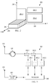
- Figure 2 is an illustration of an example of a resource block 200.
- Resource block 200 is defined in three dimensions: a frequency dimension 210, a time dimensions 220, and a code dimension 230.
- code dimension 230 each time/frequency resource unit is divided into unique codes 240, which are generated from corresponding sparse codebooks.
- Resource block 200 is partitioned into three resource regions 250-1, 250-2, and 250-3.
- the resource regions are depicted as various rectangles in the time/frequency domain.
- Resource regions can be any shape, although defining a time band and a frequency band naturally defines a rectangle in the time/frequency domain.
- Resource regions can abut one another, which is to share a boundary, or can be defined with time/frequency gaps between any two resource regions. In certain examples, gaps may be needed to achieve sufficiently low levels of inter-group interference.
- the entire resource block 200 need not be partitioned into various resource regions. In such examples, various portions of resource block 200 are unassigned.
- Resource regions are sometimes referred to as SCMA regions or multiple access regions.
- Partitioning resource block 200 is carried out by the network, such as wireless network 100 from Figure 1 . More specifically, the partitioning can be carried out by base station 110.
- Each of resource regions 250-1, 250-2, and 250-3 are assigned to a respective device group, which is referred to as a resource region assignment.
- Resource regions are generally contiguously defined in the time/frequency domain. In the case of a non-contiguous resource region, the various pieces of the non-contiguous resource region are treated as independent resource regions assigned to a common device group. In examples having spectrum shaping filters, each non-contiguous piece of resource region would have a dedicated filter. In examples having resource regions assuming shapes other than rectangles, multiple spectrum shaping filters would be needed. For this reason, rectangular-shaped resource regions are desirable, although alternative implementations with otherwise-shaped resource regions are possible.
- device groups 120-1, 120-2, and 120-3 can be respectively assigned, for example, to resource regions 250-1, 250-2, and 250-3.
- Resource region assignments are then communicated, or signaled, to the individual devices by base station 110.
- the resource region assignments can be communicated to the various device groups using multicast signaling.
- devices 130 then make their respective SCMA transmissions using their respective assigned resource region.
- FIG. 3 is a block diagram of one embodiment of a base station 300.
- Base station 300 includes an antenna 310, a mixer 320, couplers 330-1 and 330-2, filters 340-1, 340-2, and 340-3, and processor 350.
- Base station 300 also includes a transmit stage 360 and another antenna 370.
- Base station 300 can also include a variety of other components not illustrated in Figure 3 , such as amplifiers, analog-to-digital converters, decoders, application specific integrated circuits (ASICS), field programmable gate arrays (FPGAs), dedicated logic circuitry, oscillators, and many other components.
- ASICS application specific integrated circuits
- FPGAs field programmable gate arrays
- These additional components, in various embodiments of base station 300 can appear anywhere in the circuit illustrated in Figure 3 , including between any two elements of base station 300.
- Antenna 310 is configured to receive SCMA signals from various transmit devices.
- the SCMA transmissions are made using filtered OFDMA waveforms.
- filtered OFDMA For further information on filtered OFDMA, refer to U.S. Patent Application No. 14/231,217 .
- the received SCMA signals are radio frequency (RF) transmissions that are down-converted by mixer 320 to baseband signals.
- the baseband SCMA signals are then passed through filters 340-1, 340-2, and 340-3.
- the received SCMA signals arrive at base station 300 on channels defined by respective allocations of time and frequency resources.
- processor 350 allocates to processor 350 according to a partitioning of a resource block into resource regions, as in, for example, resource block 200 of Figure 2 , and assignment of those resource regions to respective device groups, such as device groups 120-1, 120-2, and 120-3 of Figure 1 .
- the respective device groups contain the various transmit devices.
- Resource region assignments made by processor 350 are communicated to the various transmit devices through transmit stage 360 and antenna 370.
- the various transmit devices are grouped into device groups by base station 300, particularly processor 350.
- the base station may transmit, and a UE may receive, a message indicating a plurality of UEs belonging to a device group of which the UE is a member.
- the various transmit devices themselves form the device groups.
- a UE may determine a composition of a device group according to respective locations of a plurality of UEs in the device group.
- the groupings or compositions of the device groups are communicated by message from the devices or UEs of the respective device groups to base station 300.
- the UE may communicate by message the devices or UEs belonging to its device group to the base station, or to at least one other UE of the UEs in the device group.
- the grouping of the various transmit devices can be done according to a variety of parameters, including the respective locations of the various transmit devices and respective mobility predictions and patterns for the various transmit devices.
- Transmit devices in one device group make SCMA transmissions that are asynchronous to SCMA transmissions made by another device group.
- SCMA transmissions made by two transmit devices in the same device group are synchronous.
- the synchronous SCMA transmissions can be synchronous as a consequence of their proximity to one another or, in certain embodiments, because transmit devices in that device group are synchronized to a common reference.
- Asynchronous refers to signals from different device groups arriving at different times.
- Filters 340-1, 340-2, and 340-3 are each digital filters designed for a specific resource region to shape the spectrum such that inter-resource region interference is reduced, possibly eliminated.
- Inter-resource region interference, or inter-SCMA region interference is caused by asynchronous SCMA transmissions by transmit devices in different device groups over adjacent resource regions. In other words, interference results from two or more asynchronous SCMA transmissions over adjacent time/frequency resources.
- Filters 340-1, 340-2, and 340-3 are designed to block side-lobes of OFDMA waveforms carrying asynchronous SCMA signals in adjacent resource regions. Doing so allows base station 300 to properly receive the asynchronous SCMA signals. The filtered SCMA signals are then decoded and the payload data ultimately passed to processor 350.
- Processor 350 can be implemented in one or more processors, one or more ASICs, one or more FPGAs, dedicated logic circuitry, or any combination thereof, all collectively referred to as a processor.
- the respective functions for processor can be stored as instructions in non-transitory memory for execution by the processor.
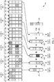
- FIG. 4 is an illustration of an SCMA encoding scheme 400.
- SCMA encoding scheme 400 uses multiple sparse codebooks 410, 420, 430, 440, 450, and 460, each of which is assigned to a different multiplexed layer and includes multiple multi-dimensional codewords. More specifically, sparse codebook 410 includes codewords 411-414, sparse codebook 420 includes codewords 421-424, sparse codebook 430 includes codewords 431-434, sparse codebook 440 includes codewords 441-444, sparse codebook 450 includes codewords 451-454, and sparse codebook 460 includes codewords 461-464. Each codeword is mapped to a different binary value.
- codewords 411, 421, 431, 441, 451, and 461 are mapped to the binary value '00
- codewords 412, 422, 432, 442, 452, and 462 are mapped to the binary value '01
- codewords 413, 423, 433, 443, 453, and 463 are mapped to the binary value '10
- codewords 414, 424, 434, 444, 454, and 464 are mapped to the binary value '11.
- sparse codebooks of the embodiment of Figure 4 include four codewords apiece
- sparse codebooks for SCMA can include any number of codewords.
- certain embodiment sparse codebooks may have eight codewords mapped to binary values '000' to '111,' while other embodiments may include 16 codewords mapped to binary values '0000' to '1111,' or more.
- codeword 414 is selected from sparse codebook 410 because the binary value '11' is to be transmitted over the first multiplexed layer.
- Codeword 422 is selected from sparse codebook 420 because the binary value '01' is being transmitted over the second multiplexed layer.
- Codeword 433 is selected from sparse codebook 430 because the binary value '10' is to be transmitted over the third multiplexed layer.
- Codeword 442 is sselected from sparse codebook 440 because the binary value '01' is to be transmitted over the fourth multiplexed layer.
- Codeword 452 is selected from sparse codebook 450 because the binary value '01' is to be transmitted over the fifth multiplexed layer.
- Codeword 464 is selected from sparse codebook 460 because the binary value '11' is to be transmitted over the sixth multiplexed layer.
- Codewords, 414, 422, 433, 442, 452, and 464 are then multiplexted together to form a multiplexed data stream 480, which is transmitted over shared resources.
- Codewords 414, 422, 433, 442, 452, and 464 are sparse codewords that can be identified upon receipt of multiplexed data stream 480 at the receiver using an MPA.
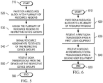
- Figure 5 is flow diagram of one embodiment of a method of resource allocation for SCMA signals.
- the method begins at a start step 510.
- a base station partitions a resource block into a plurality of resource regions.
- the resource block is defined as a block of time, frequency, and codebook resources.
- the resource regions are assigned to respective device groups. Transmit devices are grouped into the device groups according to their respective locations. In certain embodiments, the transmit devices are grouped into the device groups according to respective mobility predictions and patterns for the transmit devices.
- the resource region assignments are signaled to the transmit devices at a communicating step 540.
- the resource region assignments need not be communicated to the transmit devices for every data transmission.
- the transmit devices make their respective SCMA transmissions using their respective assigned resource regions.
- the SCMA signals are received at by the base station at a receiving step 550.
- the SCMA transmissions are asynchronous from device group to device group.
- the method also includes filtering the SCMA signals using, e.g., spectrum shaping filters corresponding to the respective resource regions, in order to filter out inter-resource region interference caused by the asynchronous transmissions. The filtering allows the base station receivers to properly receive, decode, and detect the SCMA signals.
- the method ends at an end step 560.
- Figure 6 is a flow diagram of an example of a method of receiving asynchronous SCMA signals.
- the method begins at a start step 610.
- a resource block is partitioned into a plurality of resource regions.
- the resource regions are assigned to respective device groups.
- the device groups each contain at least one transmit device, i.e., UE.
- the UEs are grouped into the device groups according to their respective locations.
- the UEs are grouped according to respective mobility predictions and patterns for the UEs.
- the grouping can be carried out, in certain examples, by the base station while, in other examples, the grouping is carried out by the UEs themselves.
- the device groups of UEs are assigned to the resource regions and the assignments are communicated to the UEs.
- the device groups can contain any number of UEs. UEs within a given device group transmit using resource region assigned to the device group.
- a first SCMA signal is received at the base station from a first UE.
- the first UE makes the first SCMA transmission using a first resource region of the plurality of resource regions.
- multiple sparse codewords, or layers can be superposed on the first resource region.
- a second SCMA signal is received at the base station from a second UE.
- the second UE makes the second SCMA transmission using a second resource region of the plurality of resource regions.
- the first SCMA transmission and the second SCMA transmission are asynchronous.
- the first UE and second UE have not been synchronized to a common reference.
- the first SCMA signal and the second SCMA signal are passed through filters designed for their respective resource regions. Each filter, designed for a specific resource region, is configured to filter out the interference caused by asynchronous SCMA transmissions from neighboring resource regions. The method ends at an end step 650.
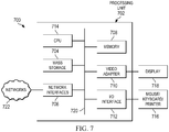
- Figure 7 is a block diagram of a computing system 700 that may be used for implementing the devices and methods disclosed herein. Specific devices may utilize all of the components shown or only a subset of the components, and levels of integration may vary from device to device.
- a device may contain multiple instances of a component, such as multiple processing units, processors, memories, transmitters, receivers, etc.
- the computing system 700 may comprise a processing unit 702 equipped with one or more input/output devices, such as a speaker, microphone, mouse, touchscreen, keypad, keyboard, printer, display, and the like.
- the processing unit may include a central processing unit (CPU) 714, memory 708, a mass storage device 704, a video adapter 710, and an I/O interface 712 connected to a bus 720.
- CPU central processing unit
- the bus 720 may be one or more of any type of several bus architectures including a memory bus or memory controller, a peripheral bus, video bus, or the like.
- the CPU 714 may comprise any type of electronic data processor.
- the memory 708 may comprise any type of non-transitory system memory such as static random access memory (SRAM), dynamic random access memory (DRAM), synchronous DRAM (SDRAM), read-only memory (ROM), a combination thereof, or the like.
- the memory 708 may include ROM for use at boot-up, and DRAM for program and data storage for use while executing programs.
- the mass storage 704 may comprise any type of non-transitory storage device configured to store data, programs, and other information and to make the data, programs, and other information accessible via the bus 720.
- the mass storage 704 may comprise, for example, one or more of a solid state drive, hard disk drive, a magnetic disk drive, an optical disk drive, or the like.
- the video adapter 710 and the I/O interface 712 provide interfaces to couple external input and output devices to the processing unit 702.
- input and output devices include a display 718 coupled to the video adapter 710 and a mouse/keyboard/printer 716 coupled to the I/O interface 712.
- Other devices may be coupled to the processing unit 702, and additional or fewer interface cards may be utilized.
- a serial interface such as Universal Serial Bus (USB) (not shown) may be used to provide an interface for a printer.
- USB Universal Serial Bus
- the processing unit 702 also includes one or more network interfaces 706, which may comprise wired links, such as an Ethernet cable or the like, and/or wireless links to access nodes or different networks.
- the network interfaces 706 allow the processing unit 702 to communicate with remote units via the networks.
- the network interfaces 706 may provide wireless communication via one or more transmitters/transmit antennas and one or more receivers/receive antennas.
- the processing unit 702 is coupled to a local-area network 722 or a wide-area network for data processing and communications with remote devices, such as other processing units, the Internet, remote storage facilities, or the like.
- a base station in accordance with one embodiment of the invention, includes a processor, a transmitter, and a receiver.
- the processor is configured to partition a resource block into a plurality of resource regions and assign the plurality of resource regions to respective device groups.
- the transmitter is operatively coupled to the processor and is configured to signal resource region assignments to devices of the respective device groups.
- the receiver is operatively coupled to the processor and is configured to receive sparse code multiple access (SCMA) signals from the devices of the respective device groups.
- SCMA sparse code multiple access
- a UE in accordance with another example of the invention, includes a receiver to configured to receive a resource region assignment indicating a resource region allocated to a device group of which the UE is a member; filter a sparse code multiple access (SCMA) signal using a spectrum shaping filter corresponding to the resource region; and transmit the filtered SCMA signal toward a base station using time and frequency resources of the resource region according to the resource region assignment.
- SCMA sparse code multiple access
- the transmitting is carried out synchronously with a local timing reference for the device group.
Landscapes
- Engineering & Computer Science (AREA)
- Signal Processing (AREA)
- Computer Networks & Wireless Communication (AREA)
- Mobile Radio Communication Systems (AREA)
Description
- The present invention relates generally to sparse code multiple access (SCMA), and, in particular embodiments, to a methods, a base station and a device for SCMA signal transmissions.
- SCMA is a non-orthogonal multiple access scheme that allows multiple devices, users, or user equipments (UEs) to share channel resources. Potential transmit devices are allocated time and frequency resources, also referred to as resource units. In SCMA, potential transmit devices are also assigned a sparse codebook that allows superposition of device transmissions, which allows SCMA systems to support more connected devices.
- In grant-free SCMA systems, there is no signaling from the network to devices for scheduling transmissions. The devices access the shared channel resources in a contention based manner. Contention based access begins to break down when two or more devices attempt to transmit using the same resources, which is referred to as a collision. SCMA can tolerate some amount of signal collision. SCMA systems can control the probability of collision using collision avoidance and collision detection and recovery techniques to mitigate its impact. Base station receivers generally need arriving signals to be synchronized in time in order to receive them correctly and take advantage of low complexity message passing algorithm (MPA) receivers. That synchronizing is typically achieved through signaling from the base station to the transmitting devices indicating timing adjustments to transmit timing.
-
EP 2 479 910 A2US 2014/0286284 A1 disclose related technologies regarding resource allocation. Hosein Nikopour Et: "Sparse Code Mulitple Access", 2013 IEEE 24th International Symposium on Personal, Indoor and Mobile Radio Communications: Fundamentals and PHY Track, discloses the use of SCMA. - An embodiment method of resource allocation for SCMA waveform-based signals in a base station is defined in
claim 1. An embodiment base station adapted for resource allocation for SCMA waveform-based signals is defined inclaim 5. An embodiment method of transmitting an SCMA signal in a device and a corresponding embodiment device are defined in claim 9 and 12, respectively. - For a more complete understanding of the present invention, and the advantages thereof, reference is now made to the following descriptions taken in conjunction with the accompanying drawings, in which:
-
Figure 1 is a diagram of an example of a wireless network; -
Figure 2 is an illustration of an example of a resource block; -
Figure 3 is a block diagram of one embodiment of a base station; -
Figure 4 is an illustration of an SCMA encoding scheme; -
Figure 5 is a flow diagram of one embodiment of a method of resource allocation for SCMA transmissions; -
Figure 6 is a flow diagram of an example of a method of receiving asynchronous SCMA transmissions; and -
Figure 7 is a block diagram of an example of a computing system. - In an embodiment, SCMA encoding encodes binary data streams directly to multi-dimensional codewords rather than using a quadrature amplitude modulation (QAM) symbol, as is done in code division multiple access (CDMA). SCMA encoding provides multiple access by assigning different sparse codewords generated from sparse codebooks for each multiplexed layer, as opposed to using spreading sequences common in CDMA encoding. A multiplexed layer is one that multiple data streams may be communicated over shared resources. For example, the shared resources can be multiple-input multiple-output (MIMO) spatial layers, orthogonal frequency division multiple access (OFDMA) tones, and time division multiple access (TDMA) layers time slots, among others. Sparse codebooks include sparse codewords that allow receivers to use low complexity MPAs to detect respective codewords among the multiplexed codewords, which reduces baseband processing complexity at the receiver. It is realized herein the general requirement that SCMA signals received at a base station should be synchronized can be relaxed. Relaxing the synchronization requirement allows a certain amount of signaling overhead to be eliminated, including timing adjustment signaling from the base station to the various transmit devices. The synchronization requirements can be relaxed, it is realized herein, by taking advantage of the simplicity with which local groups of transmit devices can be synchronized. It is further realized herein that transmit devices can be grouped together according to their location and mobility. Device groups can then be allocated, or assigned, regions of the resource block reserved for SCMA transmissions. SCMA transmissions arc made over channels defined by time and frequency resources. The resource block can be partitioned into resource regions that can be individually allocated to the device groups, thereby separating asynchronous groups of devices with respect to their time and frequency resources. It is also realized herein that asynchronous SCMA transmissions in adjacent resource regions can create inter-resource region interference. To mitigate the interference, for a given device group and assigned resource region, digital filters designed for each resource region can be used to filter out side-lobes from SCMA signals originating from other transmit devices in other device groups. It is further realized herein the filtering of the SCMA signals can occur at the transmitter, e.g., UE, mobile device, etc., and at the receiver, e.g., base station, evolved node B (eNB), etc. Certain embodiments can use analog filters for each resource region, however, these embodiments are not as flexible as digital filter embodiments that can adapt to fluctuating bandwidth requirements of various device groups and their corresponding resource regions.
Figure 1 is a diagram of an example of awireless network 100.Wireless network 100 includes abase station 110 within which the method of resource allocation and method of receiving asynchronous SCMA signals introduced herein may be embodied.Base station 110 serves one or more devices by receiving uplink (UL) communications originating from the devices and forwarding the UL communications to their respective indented destinations, or by receiving communications destined for the devices and forwarding the communications to their respective intended transmit devices.Base station 110 is sometimes referred to as an access point, a Node B, an evolved Node B (eNB), a controller, a transmit device, or a communication controller.Wireless network 100 also includes three device groups 120-1, 120-2, and 120-3. Each of the three device groups contains at least one device.Devices 130 are sometimes referred to as stations, mobile stations, mobiles, mobile devices, terminals, users, UEs, transmit devices, or subscribers. -
Devices 130 can be grouped into device groups 120-1, 120-2, and 120-3 according to a variety of parameters, including one or more of the following: respective device locations, respective device mobility predictions, and respective device mobility patterns. In certain embodiments,devices 130 can be grouped bywireless network 100 or, more specifically, bybase station 110. In other embodiments,devices 130 can group themselves. -
Devices 130 make SCMA transmissions 140-1, 140-2, and 140-3 tobase station 110. SCMA transmissions 140-1, 140-2, and 140-3 are typically made using orthogonal frequency division multiple access (OFDMA) waveforms, although other waveforms are possible. SCMA transmissions 140-1 originate fromdevices 130 within device group 120-1. Likewise, SCMA transmissions 140-2 originate fromdevices 130 within device group 120-2, and SCMA transmissions 140-3 originate fromdevices 130 within device group 120-3. SCMA transmissions from different device groups are asynchronous. In the embodiment ofFigure 1 , SCMA transmissions 140-1 are asynchronous with respect to SCMA transmissions 140-2 and 140-3. SCMA transmissions 140-2 are also asynchronous with respect to SCMA transmissions 140-3. SCMA transmissions 140-1, 140-2, and 140-3 are asynchronous in thatrespective devices 130 in device groups 120-1, 120-2, and 120-3 have not been synchronized to one another. For example,devices 130 in device group 120-1 are not synchronized withdevices 130 in device group 120-2. In certain embodiments,devices 130 within a particular device group are synchronized with each other. For example, a group of sensors located in a single building can be synchronized to a local timing reference or reference device located in the group or in the building, rather than synchronizing tobase station 110. In another example, a group of users, i.e., mobile devices, riding in a bus can synchronize to a local timing reference or reference device in the group or in the bus, rather than synchronizing tobase station 110. In other embodiments,devices 130 within the particular device group are in close enough proximity that no transmit-timing synchronization is needed forbase station 110 to properly receive their SCMA signals. - By not synchronizing
devices 130 in one device group withdevices 130 in another device group, some overhead signaling frombase station 110 can be eliminated. Typically, to globally, i.e., network - wide, synchronizedevices 130,base station 110 would signal timing adjustments to each ofdevices 130, thereby synchronizing each to a common reference. For a small number of devices, the overhead cost associated with this process is manageable. However, as the number of devices grows, the overhead cost becomes significant. -
Devices 130 make their respective SCMA transmissions using a resource block defined as a block of time and frequency resources.Devices 130 are allocated at least one time/frequency resource unit and respective sparse codebooks.Figure 2 is an illustration of an example of aresource block 200.Resource block 200 is defined in three dimensions: afrequency dimension 210, atime dimensions 220, and acode dimension 230. Incode dimension 230, each time/frequency resource unit is divided intounique codes 240, which are generated from corresponding sparse codebooks. -
Resource block 200 is partitioned into three resource regions 250-1, 250-2, and 250-3. The resource regions are depicted as various rectangles in the time/frequency domain. Resource regions can be any shape, although defining a time band and a frequency band naturally defines a rectangle in the time/frequency domain. Resource regions can abut one another, which is to share a boundary, or can be defined with time/frequency gaps between any two resource regions. In certain examples, gaps may be needed to achieve sufficiently low levels of inter-group interference. Likewise, theentire resource block 200 need not be partitioned into various resource regions. In such examples, various portions ofresource block 200 are unassigned. Resource regions are sometimes referred to as SCMA regions or multiple access regions.Partitioning resource block 200 is carried out by the network, such aswireless network 100 fromFigure 1 . More specifically, the partitioning can be carried out bybase station 110. Each of resource regions 250-1, 250-2, and 250-3 are assigned to a respective device group, which is referred to as a resource region assignment. Resource regions are generally contiguously defined in the time/frequency domain. In the case of a non-contiguous resource region, the various pieces of the non-contiguous resource region are treated as independent resource regions assigned to a common device group. In examples having spectrum shaping filters, each non-contiguous piece of resource region would have a dedicated filter. In examples having resource regions assuming shapes other than rectangles, multiple spectrum shaping filters would be needed. For this reason, rectangular-shaped resource regions are desirable, although alternative implementations with otherwise-shaped resource regions are possible. - For the example of
Figure 1 , device groups 120-1, 120-2, and 120-3 can be respectively assigned, for example, to resource regions 250-1, 250-2, and 250-3. Resource region assignments are then communicated, or signaled, to the individual devices bybase station 110. In certain embodiments, the resource region assignments can be communicated to the various device groups using multicast signaling. Again referring to the example ofFigure 1 ,devices 130 then make their respective SCMA transmissions using their respective assigned resource region. -
Figure 3 is a block diagram of one embodiment of abase station 300.Base station 300 includes anantenna 310, amixer 320, couplers 330-1 and 330-2, filters 340-1, 340-2, and 340-3, andprocessor 350.Base station 300 also includes a transmitstage 360 and anotherantenna 370.Base station 300 can also include a variety of other components not illustrated inFigure 3 , such as amplifiers, analog-to-digital converters, decoders, application specific integrated circuits (ASICS), field programmable gate arrays (FPGAs), dedicated logic circuitry, oscillators, and many other components. These additional components, in various embodiments ofbase station 300, can appear anywhere in the circuit illustrated inFigure 3 , including between any two elements ofbase station 300. -
Antenna 310 is configured to receive SCMA signals from various transmit devices. In certain embodiments, the SCMA transmissions are made using filtered OFDMA waveforms. For further information on filtered OFDMA, refer toU.S. Patent Application No. 14/231,217 . The received SCMA signals are radio frequency (RF) transmissions that are down-converted bymixer 320 to baseband signals. The baseband SCMA signals are then passed through filters 340-1, 340-2, and 340-3. The received SCMA signals arrive atbase station 300 on channels defined by respective allocations of time and frequency resources. These allocations are made byprocessor 350 according to a partitioning of a resource block into resource regions, as in, for example,resource block 200 ofFigure 2 , and assignment of those resource regions to respective device groups, such as device groups 120-1, 120-2, and 120-3 ofFigure 1 . The respective device groups contain the various transmit devices. Resource region assignments made byprocessor 350 are communicated to the various transmit devices through transmitstage 360 andantenna 370. - In certain embodiments, the various transmit devices are grouped into device groups by
base station 300, particularlyprocessor 350. The base station may transmit, and a UE may receive, a message indicating a plurality of UEs belonging to a device group of which the UE is a member. In other embodiments, the various transmit devices themselves form the device groups. For example, a UE may determine a composition of a device group according to respective locations of a plurality of UEs in the device group. The groupings or compositions of the device groups are communicated by message from the devices or UEs of the respective device groups tobase station 300. The UE may communicate by message the devices or UEs belonging to its device group to the base station, or to at least one other UE of the UEs in the device group. The grouping of the various transmit devices can be done according to a variety of parameters, including the respective locations of the various transmit devices and respective mobility predictions and patterns for the various transmit devices. Transmit devices in one device group make SCMA transmissions that are asynchronous to SCMA transmissions made by another device group. In certain embodiments, SCMA transmissions made by two transmit devices in the same device group are synchronous. The synchronous SCMA transmissions can be synchronous as a consequence of their proximity to one another or, in certain embodiments, because transmit devices in that device group are synchronized to a common reference. Asynchronous refers to signals from different device groups arriving at different times. - Filters 340-1, 340-2, and 340-3 are each digital filters designed for a specific resource region to shape the spectrum such that inter-resource region interference is reduced, possibly eliminated. Inter-resource region interference, or inter-SCMA region interference, is caused by asynchronous SCMA transmissions by transmit devices in different device groups over adjacent resource regions. In other words, interference results from two or more asynchronous SCMA transmissions over adjacent time/frequency resources. Filters 340-1, 340-2, and 340-3 are designed to block side-lobes of OFDMA waveforms carrying asynchronous SCMA signals in adjacent resource regions. Doing so allows
base station 300 to properly receive the asynchronous SCMA signals. The filtered SCMA signals are then decoded and the payload data ultimately passed toprocessor 350. -
Processor 350 can be implemented in one or more processors, one or more ASICs, one or more FPGAs, dedicated logic circuitry, or any combination thereof, all collectively referred to as a processor. The respective functions for processor can be stored as instructions in non-transitory memory for execution by the processor. -
Figure 4 is an illustration of anSCMA encoding scheme 400.SCMA encoding scheme 400 uses multiplesparse codebooks sparse codebook 410 includes codewords 411-414,sparse codebook 420 includes codewords 421-424,sparse codebook 430 includes codewords 431-434,sparse codebook 440 includes codewords 441-444,sparse codebook 450 includes codewords 451-454, andsparse codebook 460 includes codewords 461-464. Each codeword is mapped to a different binary value. In the embodiment ofFigure 4 ,codewords codewords codewords codewords Figure 4 include four codewords apiece, sparse codebooks for SCMA can include any number of codewords. For example, certain embodiment sparse codebooks may have eight codewords mapped to binary values '000' to '111,' while other embodiments may include 16 codewords mapped to binary values '0000' to '1111,' or more. - Different codewords are selected from the various sparse codebooks depending on the binary data to be transmitted over the respective multiplexed layers. In the embodiment of
Figure 4 ,codeword 414 is selected fromsparse codebook 410 because the binary value '11' is to be transmitted over the first multiplexed layer.Codeword 422 is selected fromsparse codebook 420 because the binary value '01' is being transmitted over the second multiplexed layer.Codeword 433 is selected fromsparse codebook 430 because the binary value '10' is to be transmitted over the third multiplexed layer.Codeword 442 is sselected fromsparse codebook 440 because the binary value '01' is to be transmitted over the fourth multiplexed layer.Codeword 452 is selected fromsparse codebook 450 because the binary value '01' is to be transmitted over the fifth multiplexed layer.Codeword 464 is selected fromsparse codebook 460 because the binary value '11' is to be transmitted over the sixth multiplexed layer. Codewords, 414, 422, 433, 442, 452, and 464 are then multiplexted together to form a multiplexeddata stream 480, which is transmitted over shared resources.Codewords data stream 480 at the receiver using an MPA. -
Figure 5 is flow diagram of one embodiment of a method of resource allocation for SCMA signals. The method begins at astart step 510. At apartitioning step 520, a base station partitions a resource block into a plurality of resource regions. The resource block is defined as a block of time, frequency, and codebook resources. At an assigningstep 530, the resource regions are assigned to respective device groups. Transmit devices are grouped into the device groups according to their respective locations. In certain embodiments, the transmit devices are grouped into the device groups according to respective mobility predictions and patterns for the transmit devices. - The resource region assignments are signaled to the transmit devices at a communicating
step 540. The resource region assignments need not be communicated to the transmit devices for every data transmission. The transmit devices make their respective SCMA transmissions using their respective assigned resource regions. The SCMA signals are received at by the base station at a receivingstep 550. The SCMA transmissions are asynchronous from device group to device group. In certain embodiments, the method also includes filtering the SCMA signals using, e.g., spectrum shaping filters corresponding to the respective resource regions, in order to filter out inter-resource region interference caused by the asynchronous transmissions. The filtering allows the base station receivers to properly receive, decode, and detect the SCMA signals. The method ends at anend step 560. -
Figure 6 is a flow diagram of an example of a method of receiving asynchronous SCMA signals. The method begins at astart step 610. At a base station, at apartitioning step 620, a resource block is partitioned into a plurality of resource regions. The resource regions are assigned to respective device groups. The device groups each contain at least one transmit device, i.e., UE. In certain examples, the UEs are grouped into the device groups according to their respective locations. In some examples the UEs are grouped according to respective mobility predictions and patterns for the UEs. The grouping can be carried out, in certain examples, by the base station while, in other examples, the grouping is carried out by the UEs themselves. - The device groups of UEs are assigned to the resource regions and the assignments are communicated to the UEs. The device groups can contain any number of UEs. UEs within a given device group transmit using resource region assigned to the device group. At a
first receiving step 630, a first SCMA signal is received at the base station from a first UE. The first UE makes the first SCMA transmission using a first resource region of the plurality of resource regions. In certain embodiments, multiple sparse codewords, or layers, can be superposed on the first resource region. At asecond receiving step 640, a second SCMA signal is received at the base station from a second UE. The second UE makes the second SCMA transmission using a second resource region of the plurality of resource regions. Because the first UE and the second UE are in different device groups and assigned different resource regions, the first SCMA transmission and the second SCMA transmission are asynchronous. The first UE and second UE have not been synchronized to a common reference. In certain embodiments, for the base station to properly receive the SCMA signals, the first SCMA signal and the second SCMA signal are passed through filters designed for their respective resource regions. Each filter, designed for a specific resource region, is configured to filter out the interference caused by asynchronous SCMA transmissions from neighboring resource regions. The method ends at anend step 650. -
Figure 7 is a block diagram of acomputing system 700 that may be used for implementing the devices and methods disclosed herein. Specific devices may utilize all of the components shown or only a subset of the components, and levels of integration may vary from device to device. - Furthermore, a device may contain multiple instances of a component, such as multiple processing units, processors, memories, transmitters, receivers, etc. The
computing system 700 may comprise a processing unit 702 equipped with one or more input/output devices, such as a speaker, microphone, mouse, touchscreen, keypad, keyboard, printer, display, and the like. The processing unit may include a central processing unit (CPU) 714,memory 708, amass storage device 704, avideo adapter 710, and an I/O interface 712 connected to abus 720. - The
bus 720 may be one or more of any type of several bus architectures including a memory bus or memory controller, a peripheral bus, video bus, or the like. TheCPU 714 may comprise any type of electronic data processor. Thememory 708 may comprise any type of non-transitory system memory such as static random access memory (SRAM), dynamic random access memory (DRAM), synchronous DRAM (SDRAM), read-only memory (ROM), a combination thereof, or the like. In an embodiment, thememory 708 may include ROM for use at boot-up, and DRAM for program and data storage for use while executing programs. - The
mass storage 704 may comprise any type of non-transitory storage device configured to store data, programs, and other information and to make the data, programs, and other information accessible via thebus 720. Themass storage 704 may comprise, for example, one or more of a solid state drive, hard disk drive, a magnetic disk drive, an optical disk drive, or the like. - The
video adapter 710 and the I/O interface 712 provide interfaces to couple external input and output devices to the processing unit 702. As illustrated, examples of input and output devices include adisplay 718 coupled to thevideo adapter 710 and a mouse/keyboard/printer 716 coupled to the I/O interface 712. Other devices may be coupled to the processing unit 702, and additional or fewer interface cards may be utilized. For example, a serial interface such as Universal Serial Bus (USB) (not shown) may be used to provide an interface for a printer. - The processing unit 702 also includes one or
more network interfaces 706, which may comprise wired links, such as an Ethernet cable or the like, and/or wireless links to access nodes or different networks. The network interfaces 706 allow the processing unit 702 to communicate with remote units via the networks. For example, the network interfaces 706 may provide wireless communication via one or more transmitters/transmit antennas and one or more receivers/receive antennas. In an embodiment, the processing unit 702 is coupled to a local-area network 722 or a wide-area network for data processing and communications with remote devices, such as other processing units, the Internet, remote storage facilities, or the like. - In accordance with one embodiment of the invention, a base station is also disclosed. The base station includes a processor, a transmitter, and a receiver. The processor is configured to partition a resource block into a plurality of resource regions and assign the plurality of resource regions to respective device groups. The transmitter is operatively coupled to the processor and is configured to signal resource region assignments to devices of the respective device groups. The receiver is operatively coupled to the processor and is configured to receive sparse code multiple access (SCMA) signals from the devices of the respective device groups. In the embodiment, the SCMA signals from one group of the respective device groups are asynchronous with respect to the SCMA signals from another group of the respective device groups.
- In accordance with another example of the invention, a UE is disclosed. The UE includes a receiver to configured to receive a resource region assignment indicating a resource region allocated to a device group of which the UE is a member; filter a sparse code multiple access (SCMA) signal using a spectrum shaping filter corresponding to the resource region; and transmit the filtered SCMA signal toward a base station using time and frequency resources of the resource region according to the resource region assignment. In the embodiment, the transmitting is carried out synchronously with a local timing reference for the device group.
Claims (14)
- A method of resource allocation for sparse code multiple access, SCMA, signals in a base station, comprising:signaling (540) resource region assignments to devices of respective device groups, wherein the resource region assignments assign a plurality of resource regions of a resource block to the respective device groups; andreceiving (550) the SCMA signals from the devices of the respective device groups, wherein the SCMA waveform-based signals from one group of the respective device groups are asynchronous with respect to the SCMA waveform-based signals from another group of the respective device groups, and wherein the devices of the one group of the respective device groups are synchronized with other devices of the one group.
- The method of Claim 1 further comprising filtering received SCMA waveform-based signals, wherein the filtering is carried out by respective spectrum shaping filters for the plurality of resource regions.
- The method of Claim 1 further comprising transmitting a message to the devices indicating a grouping of the devices into the respective device groups according to respective locations of the devices or respective mobility predictions for the devices.
- The method of Claim 1, further comprising receiving a message from a device of the respective device groups indicating a grouping of the devices into respective device groups.
- Base station (110, 300) adapted for resource allocation for sparse code multiple access, SCMA, signals, comprising:a transmitter (360) adapted to signal resource region assignments to devices of the respective device groups, wherein the resource region assignments assign a plurality of resource regions of a resource block to the respective device groups; anda receiver adapted to receive the SCMA waveform-based signals from the devices of the respective device groups, wherein the SCMA waveform-based signals from one group of the respective device groups are asynchronous with respect to the SCMA waveform-based signals from another group of the respective device groups, and wherein the devices of the one group of the respective device groups are synchronized with other devices of the one group.
- The base station of Claim 5, further comprising respective spectrum shaping filters adapted to filter received SCMA waveform-based signals from the devices of the respective device groups for the plurality of resource regions.
- The base station of Claim 5, wherein the transmitter is adapted to transmit a message to the devices indicating a grouping of the devices into the respective device groups according to respective locations of the devices or respective mobility predictions for the devices.
- The base station of Claim 5, wherein the receiver is further adapted to receive a message from a device of the respective device groups indicating a grouping of the devices into respective device groups.
- A method of transmitting a sparse code multiple access, SCMA, signal in a device, comprising:receiving, from a base station, a resource region assignment indicating a resource region of a resource block assigned to a device group of which the device is a member;andtransmitting an SCMA waveform-based signal to the base station using time and frequency resources of the resource region assigned according to the resource region assignment, wherein the devices of the device group of which the device is a member are synchronized with other devices in said device group and the transmitting is carried out synchronously with a local timing reference for the device group.
- The method of Claim 9, further comprising:determining a composition of the device group according to respective locations of a plurality of devices in the device group; andcommunicating the composition of the device group to the base station.
- The method of Claim 9, further comprising receiving, from the base station, a message indicating a plurality of devices belonging to the device group from the base station.
- A device adapted to transmit a sparse code multiple access, SCMA, signal, comprising a processing unit configured to
receive, from a base station, a resource region assignment indicating a resource region of a resource block assigned to a device group of which the device is a member;
and
transmit an SCMA waveform-based signal to the base station using time and frequency resources of the resource region assigned according to the resource region assignment, wherein the devices of the device group of which the device is a member are synchronized with other devices in said device group and the transmitting is carried out synchronously with a local timing reference for the device group. - The device of Claim 12, wherein the processing unit is further configured to
determine a composition of the device group according to respective locations of a plurality of devices in the device group; and
communicate the composition of the device group to the base station. - The device of Claim 12, wherein the processing unit is further configured to receive, from the base station, a message indicating a plurality of devices belonging to the device group from the base station.
Applications Claiming Priority (3)
| Application Number | Priority Date | Filing Date | Title |
|---|---|---|---|
| US14/231,217 US9419770B2 (en) | 2014-03-31 | 2014-03-31 | Method and apparatus for asynchronous OFDMA/SC-FDMA |
| US14/668,577 US10531432B2 (en) | 2015-03-25 | 2015-03-25 | System and method for resource allocation for sparse code multiple access transmissions |
| PCT/CN2015/075434 WO2015149668A1 (en) | 2014-03-31 | 2015-03-31 | System and method for resource allocation for sparse code multiple access transmissions |
Publications (3)
| Publication Number | Publication Date |
|---|---|
| EP3078122A1 EP3078122A1 (en) | 2016-10-12 |
| EP3078122A4 EP3078122A4 (en) | 2017-02-22 |
| EP3078122B1 true EP3078122B1 (en) | 2020-04-15 |
Family
ID=54239392
Family Applications (1)
| Application Number | Title | Priority Date | Filing Date |
|---|---|---|---|
| EP15772186.1A Active EP3078122B1 (en) | 2014-03-31 | 2015-03-31 | System and method for resource allocation for sparse code multiple access transmissions |
Country Status (5)
| Country | Link |
|---|---|
| EP (1) | EP3078122B1 (en) |
| JP (2) | JP6702527B2 (en) |
| KR (1) | KR101882464B1 (en) |
| CN (1) | CN106464314B (en) |
| WO (1) | WO2015149668A1 (en) |
Families Citing this family (16)
| Publication number | Priority date | Publication date | Assignee | Title |
|---|---|---|---|---|
| WO2017071586A1 (en) * | 2015-10-30 | 2017-05-04 | Huawei Technologies Co., Ltd. | System and method for high-rate sparse code multiple access in downlink |
| CN105898759B (en) * | 2016-05-30 | 2019-03-26 | 西安电子科技大学 | Resource allocation methods based on SCMA multiple access access mechanism |
| CN107592652B (en) * | 2016-07-07 | 2021-06-01 | 华为技术有限公司 | Data transmission method and device |
| CN106304306B (en) * | 2016-07-27 | 2019-04-23 | 西安电子科技大学 | The method for managing resource of multiple access access is mixed in heterogeneous network |
| JP6631929B2 (en) * | 2016-08-10 | 2020-01-15 | シャープ株式会社 | Communication system, base station device, terminal device, communication method and program |
| WO2018031938A1 (en) * | 2016-08-12 | 2018-02-15 | Cohere Technologies | Multi-user multiplexing of orthogonal time frequency space signals |
| US10523482B2 (en) * | 2016-11-23 | 2019-12-31 | Wipro Limited | System and method for providing improved non-orthogonal multiple access in a wireless communication network |
| KR102206068B1 (en) | 2017-03-24 | 2021-01-21 | 삼성전자주식회사 | Apparatus and method for uplink transmissions in wireless communication system |
| CN107231684B (en) * | 2017-06-23 | 2020-01-07 | 哈尔滨工业大学 | SCMA (Single chip multiple Access) system three-level power distribution method based on maximum capacity |
| KR102329272B1 (en) | 2017-08-04 | 2021-11-19 | 삼성전자주식회사 | Apparatus and method for uplink transmissions in wireless communication system |
| KR102415470B1 (en) | 2017-09-29 | 2022-07-01 | 삼성전자 주식회사 | Apparatus and method for transmitting reference signals in wireless communication system |
| CN107994935B (en) * | 2017-11-20 | 2020-07-17 | 清华大学 | Sparse code multiple access method, base station, device and system |
| CN108848482B (en) * | 2018-06-12 | 2021-03-16 | 南京邮电大学 | Resource allocation method based on mMTC layered access framework |
| CN109039534B (en) * | 2018-06-20 | 2021-06-11 | 东南大学 | Sparse code division multiple access signal detection method based on deep neural network |
| KR102685897B1 (en) | 2019-09-02 | 2024-07-19 | 삼성전자주식회사 | Apparatus and method for transmitting and receiving asynchronous signal in wireless communication system |
| KR102649430B1 (en) | 2019-10-15 | 2024-03-20 | 삼성전자주식회사 | Apparatus and method for non orthogonal multiple access in wireless communication system |
Family Cites Families (13)
| Publication number | Priority date | Publication date | Assignee | Title |
|---|---|---|---|---|
| US8891637B2 (en) * | 2006-02-08 | 2014-11-18 | Qualcomm Incorporated | Spectral shaping to reduce peak-to-average ratio in wireless communication |
| CN101034921B (en) * | 2006-03-10 | 2011-09-14 | 华为技术有限公司 | Method, network and device for multi-media broadcast and multi-cast service transmission |
| JP4676533B2 (en) * | 2006-07-14 | 2011-04-27 | 富士通株式会社 | Mobile communication system and base station |
| JP4189417B2 (en) * | 2006-08-28 | 2008-12-03 | 株式会社東芝 | Wireless communication apparatus and method |
| CN101232484B (en) * | 2007-01-26 | 2011-08-17 | 电信科学技术研究院 | Signal transmission method, apparatus and communication system |
| WO2008115393A2 (en) * | 2007-03-15 | 2008-09-25 | Interdigital Technology Corporation | Group resource allocation, scheduling and signaling in wireless communications |
| CN101567714A (en) * | 2008-04-24 | 2009-10-28 | 夏普株式会社 | Subband decision method, base station, subscriber device and communication system for information feedback |
| WO2010102435A1 (en) * | 2009-03-09 | 2010-09-16 | Huawei Technologies Co., Ltd. | Method and apparatus of a multiple-access communication system |
| US20120213196A1 (en) * | 2009-12-03 | 2012-08-23 | Jae Hoon Chung | Method and apparatus for efficient contention-based transmission in a wireless communication system |
| US9270427B2 (en) * | 2010-01-11 | 2016-02-23 | Futurewei Technologies, Inc. | System and method for multiplexing control and data channels in a multiple input, multiple output communications system |
| WO2012048218A1 (en) * | 2010-10-07 | 2012-04-12 | Research In Motion Limited | Sparse codes for mimo channel and detector alternatives for sparse code |
| CN104012013B (en) * | 2011-10-24 | 2018-01-23 | Lg电子株式会社 | A kind of D2D for sending signal in a wireless communication system(Equipment is to equipment)Equipment and signal sending method |
| KR20150023047A (en) * | 2012-07-26 | 2015-03-04 | 후지쯔 가부시끼가이샤 | Base station device, mobile station device, communication system, and communication method |
-
2015
- 2015-03-31 CN CN201580018161.6A patent/CN106464314B/en active Active
- 2015-03-31 KR KR1020167021415A patent/KR101882464B1/en active IP Right Grant
- 2015-03-31 EP EP15772186.1A patent/EP3078122B1/en active Active
- 2015-03-31 JP JP2016552492A patent/JP6702527B2/en active Active
- 2015-03-31 WO PCT/CN2015/075434 patent/WO2015149668A1/en active Application Filing
-
2019
- 2019-07-05 JP JP2019126437A patent/JP2019165516A/en active Pending
Non-Patent Citations (1)
| Title |
|---|
| None * |
Also Published As
| Publication number | Publication date |
|---|---|
| CN106464314A (en) | 2017-02-22 |
| EP3078122A4 (en) | 2017-02-22 |
| KR101882464B1 (en) | 2018-07-27 |
| JP2019165516A (en) | 2019-09-26 |
| KR20160106664A (en) | 2016-09-12 |
| JP2017513276A (en) | 2017-05-25 |
| WO2015149668A1 (en) | 2015-10-08 |
| EP3078122A1 (en) | 2016-10-12 |
| JP6702527B2 (en) | 2020-06-03 |
| CN106464314B (en) | 2019-11-15 |
Similar Documents
| Publication | Publication Date | Title |
|---|---|---|
| EP3078122B1 (en) | System and method for resource allocation for sparse code multiple access transmissions | |
| US11063712B2 (en) | Systems and methods for OFDM with flexible sub-carrier spacing and symbol duration | |
| US10361747B2 (en) | Hopping synchronization signals | |
| US10531432B2 (en) | System and method for resource allocation for sparse code multiple access transmissions | |
| US9439194B2 (en) | Method for robust real-time wireless industrial communication | |
| CN111654461A (en) | System and method for increasing low density signature space |
Legal Events
| Date | Code | Title | Description |
|---|---|---|---|
| PUAI | Public reference made under article 153(3) epc to a published international application that has entered the european phase |
Free format text: ORIGINAL CODE: 0009012 |
|
| 17P | Request for examination filed |
Effective date: 20160706 |
|
| AK | Designated contracting states |
Kind code of ref document: A1 Designated state(s): AL AT BE BG CH CY CZ DE DK EE ES FI FR GB GR HR HU IE IS IT LI LT LU LV MC MK MT NL NO PL PT RO RS SE SI SK SM TR |
|
| AX | Request for extension of the european patent |
Extension state: BA ME |
|
| A4 | Supplementary search report drawn up and despatched |
Effective date: 20170120 |
|
| RIC1 | Information provided on ipc code assigned before grant |
Ipc: H04B 1/707 20110101ALI20170116BHEP Ipc: H04J 11/00 20060101ALI20170116BHEP Ipc: H04J 13/00 20110101ALI20170116BHEP Ipc: H04B 7/02 20170101AFI20170116BHEP |
|
| DAV | Request for validation of the european patent (deleted) | ||
| DAX | Request for extension of the european patent (deleted) | ||
| STAA | Information on the status of an ep patent application or granted ep patent |
Free format text: STATUS: EXAMINATION IS IN PROGRESS |
|
| 17Q | First examination report despatched |
Effective date: 20180416 |
|
| GRAP | Despatch of communication of intention to grant a patent |
Free format text: ORIGINAL CODE: EPIDOSNIGR1 |
|
| STAA | Information on the status of an ep patent application or granted ep patent |
Free format text: STATUS: GRANT OF PATENT IS INTENDED |
|
| INTG | Intention to grant announced |
Effective date: 20191024 |
|
| GRAS | Grant fee paid |
Free format text: ORIGINAL CODE: EPIDOSNIGR3 |
|
| GRAA | (expected) grant |
Free format text: ORIGINAL CODE: 0009210 |
|
| STAA | Information on the status of an ep patent application or granted ep patent |
Free format text: STATUS: THE PATENT HAS BEEN GRANTED |
|
| AK | Designated contracting states |
Kind code of ref document: B1 Designated state(s): AL AT BE BG CH CY CZ DE DK EE ES FI FR GB GR HR HU IE IS IT LI LT LU LV MC MK MT NL NO PL PT RO RS SE SI SK SM TR |
|
| REG | Reference to a national code |
Ref country code: CH Ref legal event code: EP |
|
| REG | Reference to a national code |
Ref country code: DE Ref legal event code: R096 Ref document number: 602015050773 Country of ref document: DE |
|
| REG | Reference to a national code |
Ref country code: IE Ref legal event code: FG4D |
|
| REG | Reference to a national code |
Ref country code: AT Ref legal event code: REF Ref document number: 1258510 Country of ref document: AT Kind code of ref document: T Effective date: 20200515 |
|
| REG | Reference to a national code |
Ref country code: NL Ref legal event code: MP Effective date: 20200415 |
|
| REG | Reference to a national code |
Ref country code: LT Ref legal event code: MG4D |
|
| PG25 | Lapsed in a contracting state [announced via postgrant information from national office to epo] |
Ref country code: IS Free format text: LAPSE BECAUSE OF FAILURE TO SUBMIT A TRANSLATION OF THE DESCRIPTION OR TO PAY THE FEE WITHIN THE PRESCRIBED TIME-LIMIT Effective date: 20200815 Ref country code: FI Free format text: LAPSE BECAUSE OF FAILURE TO SUBMIT A TRANSLATION OF THE DESCRIPTION OR TO PAY THE FEE WITHIN THE PRESCRIBED TIME-LIMIT Effective date: 20200415 Ref country code: PT Free format text: LAPSE BECAUSE OF FAILURE TO SUBMIT A TRANSLATION OF THE DESCRIPTION OR TO PAY THE FEE WITHIN THE PRESCRIBED TIME-LIMIT Effective date: 20200817 Ref country code: SE Free format text: LAPSE BECAUSE OF FAILURE TO SUBMIT A TRANSLATION OF THE DESCRIPTION OR TO PAY THE FEE WITHIN THE PRESCRIBED TIME-LIMIT Effective date: 20200415 Ref country code: NL Free format text: LAPSE BECAUSE OF FAILURE TO SUBMIT A TRANSLATION OF THE DESCRIPTION OR TO PAY THE FEE WITHIN THE PRESCRIBED TIME-LIMIT Effective date: 20200415 Ref country code: LT Free format text: LAPSE BECAUSE OF FAILURE TO SUBMIT A TRANSLATION OF THE DESCRIPTION OR TO PAY THE FEE WITHIN THE PRESCRIBED TIME-LIMIT Effective date: 20200415 Ref country code: GR Free format text: LAPSE BECAUSE OF FAILURE TO SUBMIT A TRANSLATION OF THE DESCRIPTION OR TO PAY THE FEE WITHIN THE PRESCRIBED TIME-LIMIT Effective date: 20200716 Ref country code: NO Free format text: LAPSE BECAUSE OF FAILURE TO SUBMIT A TRANSLATION OF THE DESCRIPTION OR TO PAY THE FEE WITHIN THE PRESCRIBED TIME-LIMIT Effective date: 20200715 |
|
| REG | Reference to a national code |
Ref country code: AT Ref legal event code: MK05 Ref document number: 1258510 Country of ref document: AT Kind code of ref document: T Effective date: 20200415 |
|
| PG25 | Lapsed in a contracting state [announced via postgrant information from national office to epo] |
Ref country code: BG Free format text: LAPSE BECAUSE OF FAILURE TO SUBMIT A TRANSLATION OF THE DESCRIPTION OR TO PAY THE FEE WITHIN THE PRESCRIBED TIME-LIMIT Effective date: 20200715 Ref country code: RS Free format text: LAPSE BECAUSE OF FAILURE TO SUBMIT A TRANSLATION OF THE DESCRIPTION OR TO PAY THE FEE WITHIN THE PRESCRIBED TIME-LIMIT Effective date: 20200415 Ref country code: HR Free format text: LAPSE BECAUSE OF FAILURE TO SUBMIT A TRANSLATION OF THE DESCRIPTION OR TO PAY THE FEE WITHIN THE PRESCRIBED TIME-LIMIT Effective date: 20200415 Ref country code: LV Free format text: LAPSE BECAUSE OF FAILURE TO SUBMIT A TRANSLATION OF THE DESCRIPTION OR TO PAY THE FEE WITHIN THE PRESCRIBED TIME-LIMIT Effective date: 20200415 |
|
| PG25 | Lapsed in a contracting state [announced via postgrant information from national office to epo] |
Ref country code: AL Free format text: LAPSE BECAUSE OF FAILURE TO SUBMIT A TRANSLATION OF THE DESCRIPTION OR TO PAY THE FEE WITHIN THE PRESCRIBED TIME-LIMIT Effective date: 20200415 |
|
| REG | Reference to a national code |
Ref country code: DE Ref legal event code: R097 Ref document number: 602015050773 Country of ref document: DE |
|
| PG25 | Lapsed in a contracting state [announced via postgrant information from national office to epo] |
Ref country code: AT Free format text: LAPSE BECAUSE OF FAILURE TO SUBMIT A TRANSLATION OF THE DESCRIPTION OR TO PAY THE FEE WITHIN THE PRESCRIBED TIME-LIMIT Effective date: 20200415 Ref country code: DK Free format text: LAPSE BECAUSE OF FAILURE TO SUBMIT A TRANSLATION OF THE DESCRIPTION OR TO PAY THE FEE WITHIN THE PRESCRIBED TIME-LIMIT Effective date: 20200415 Ref country code: SM Free format text: LAPSE BECAUSE OF FAILURE TO SUBMIT A TRANSLATION OF THE DESCRIPTION OR TO PAY THE FEE WITHIN THE PRESCRIBED TIME-LIMIT Effective date: 20200415 Ref country code: EE Free format text: LAPSE BECAUSE OF FAILURE TO SUBMIT A TRANSLATION OF THE DESCRIPTION OR TO PAY THE FEE WITHIN THE PRESCRIBED TIME-LIMIT Effective date: 20200415 Ref country code: ES Free format text: LAPSE BECAUSE OF FAILURE TO SUBMIT A TRANSLATION OF THE DESCRIPTION OR TO PAY THE FEE WITHIN THE PRESCRIBED TIME-LIMIT Effective date: 20200415 Ref country code: CZ Free format text: LAPSE BECAUSE OF FAILURE TO SUBMIT A TRANSLATION OF THE DESCRIPTION OR TO PAY THE FEE WITHIN THE PRESCRIBED TIME-LIMIT Effective date: 20200415 Ref country code: RO Free format text: LAPSE BECAUSE OF FAILURE TO SUBMIT A TRANSLATION OF THE DESCRIPTION OR TO PAY THE FEE WITHIN THE PRESCRIBED TIME-LIMIT Effective date: 20200415 Ref country code: IT Free format text: LAPSE BECAUSE OF FAILURE TO SUBMIT A TRANSLATION OF THE DESCRIPTION OR TO PAY THE FEE WITHIN THE PRESCRIBED TIME-LIMIT Effective date: 20200415 |
|
| PLBE | No opposition filed within time limit |
Free format text: ORIGINAL CODE: 0009261 |
|
| STAA | Information on the status of an ep patent application or granted ep patent |
Free format text: STATUS: NO OPPOSITION FILED WITHIN TIME LIMIT |
|
| PG25 | Lapsed in a contracting state [announced via postgrant information from national office to epo] |
Ref country code: SK Free format text: LAPSE BECAUSE OF FAILURE TO SUBMIT A TRANSLATION OF THE DESCRIPTION OR TO PAY THE FEE WITHIN THE PRESCRIBED TIME-LIMIT Effective date: 20200415 Ref country code: PL Free format text: LAPSE BECAUSE OF FAILURE TO SUBMIT A TRANSLATION OF THE DESCRIPTION OR TO PAY THE FEE WITHIN THE PRESCRIBED TIME-LIMIT Effective date: 20200415 |
|
| 26N | No opposition filed |
Effective date: 20210118 |
|
| PG25 | Lapsed in a contracting state [announced via postgrant information from national office to epo] |
Ref country code: SI Free format text: LAPSE BECAUSE OF FAILURE TO SUBMIT A TRANSLATION OF THE DESCRIPTION OR TO PAY THE FEE WITHIN THE PRESCRIBED TIME-LIMIT Effective date: 20200415 |
|
| PG25 | Lapsed in a contracting state [announced via postgrant information from national office to epo] |
Ref country code: MC Free format text: LAPSE BECAUSE OF FAILURE TO SUBMIT A TRANSLATION OF THE DESCRIPTION OR TO PAY THE FEE WITHIN THE PRESCRIBED TIME-LIMIT Effective date: 20200415 |
|
| REG | Reference to a national code |
Ref country code: CH Ref legal event code: PL |
|
| GBPC | Gb: european patent ceased through non-payment of renewal fee |
Effective date: 20210331 |
|
| REG | Reference to a national code |
Ref country code: BE Ref legal event code: MM Effective date: 20210331 |
|
| PG25 | Lapsed in a contracting state [announced via postgrant information from national office to epo] |
Ref country code: LU Free format text: LAPSE BECAUSE OF NON-PAYMENT OF DUE FEES Effective date: 20210331 Ref country code: LI Free format text: LAPSE BECAUSE OF NON-PAYMENT OF DUE FEES Effective date: 20210331 Ref country code: CH Free format text: LAPSE BECAUSE OF NON-PAYMENT OF DUE FEES Effective date: 20210331 Ref country code: FR Free format text: LAPSE BECAUSE OF NON-PAYMENT OF DUE FEES Effective date: 20210331 Ref country code: GB Free format text: LAPSE BECAUSE OF NON-PAYMENT OF DUE FEES Effective date: 20210331 Ref country code: IE Free format text: LAPSE BECAUSE OF NON-PAYMENT OF DUE FEES Effective date: 20210331 |
|
| PG25 | Lapsed in a contracting state [announced via postgrant information from national office to epo] |
Ref country code: BE Free format text: LAPSE BECAUSE OF NON-PAYMENT OF DUE FEES Effective date: 20210331 |
|
| PG25 | Lapsed in a contracting state [announced via postgrant information from national office to epo] |
Ref country code: HU Free format text: LAPSE BECAUSE OF FAILURE TO SUBMIT A TRANSLATION OF THE DESCRIPTION OR TO PAY THE FEE WITHIN THE PRESCRIBED TIME-LIMIT; INVALID AB INITIO Effective date: 20150331 |
|
| PG25 | Lapsed in a contracting state [announced via postgrant information from national office to epo] |
Ref country code: CY Free format text: LAPSE BECAUSE OF FAILURE TO SUBMIT A TRANSLATION OF THE DESCRIPTION OR TO PAY THE FEE WITHIN THE PRESCRIBED TIME-LIMIT Effective date: 20200415 |
|
| PG25 | Lapsed in a contracting state [announced via postgrant information from national office to epo] |
Ref country code: MK Free format text: LAPSE BECAUSE OF FAILURE TO SUBMIT A TRANSLATION OF THE DESCRIPTION OR TO PAY THE FEE WITHIN THE PRESCRIBED TIME-LIMIT Effective date: 20200415 |
|
| PGFP | Annual fee paid to national office [announced via postgrant information from national office to epo] |
Ref country code: DE Payment date: 20240206 Year of fee payment: 10 |
|
| PG25 | Lapsed in a contracting state [announced via postgrant information from national office to epo] |
Ref country code: TR Free format text: LAPSE BECAUSE OF FAILURE TO SUBMIT A TRANSLATION OF THE DESCRIPTION OR TO PAY THE FEE WITHIN THE PRESCRIBED TIME-LIMIT Effective date: 20200415 |