EP3077726B1 - Cooling a combustor heat shield proximate a quench aperture - Google Patents
Cooling a combustor heat shield proximate a quench aperture Download PDFInfo
- Publication number
- EP3077726B1 EP3077726B1 EP14867256.1A EP14867256A EP3077726B1 EP 3077726 B1 EP3077726 B1 EP 3077726B1 EP 14867256 A EP14867256 A EP 14867256A EP 3077726 B1 EP3077726 B1 EP 3077726B1
- Authority
- EP
- European Patent Office
- Prior art keywords
- effusion
- assembly
- effusion outlet
- heat shield
- outlet
- Prior art date
- Legal status (The legal status is an assumption and is not a legal conclusion. Google has not performed a legal analysis and makes no representation as to the accuracy of the status listed.)
- Active
Links
- 238000001816 cooling Methods 0.000 title claims description 43
- 238000010791 quenching Methods 0.000 title claims description 37
- 230000002093 peripheral effect Effects 0.000 claims description 3
- 238000011144 upstream manufacturing Methods 0.000 claims description 3
- 238000002485 combustion reaction Methods 0.000 description 15
- 239000000446 fuel Substances 0.000 description 7
- 239000000203 mixture Substances 0.000 description 3
- 238000003491 array Methods 0.000 description 2
- 230000003247 decreasing effect Effects 0.000 description 2
- 230000000712 assembly Effects 0.000 description 1
- 238000000429 assembly Methods 0.000 description 1
- 230000004888 barrier function Effects 0.000 description 1
- 230000001419 dependent effect Effects 0.000 description 1
- 230000008646 thermal stress Effects 0.000 description 1
Images


Classifications
-
- F—MECHANICAL ENGINEERING; LIGHTING; HEATING; WEAPONS; BLASTING
- F23—COMBUSTION APPARATUS; COMBUSTION PROCESSES
- F23R—GENERATING COMBUSTION PRODUCTS OF HIGH PRESSURE OR HIGH VELOCITY, e.g. GAS-TURBINE COMBUSTION CHAMBERS
- F23R3/00—Continuous combustion chambers using liquid or gaseous fuel
- F23R3/02—Continuous combustion chambers using liquid or gaseous fuel characterised by the air-flow or gas-flow configuration
- F23R3/04—Air inlet arrangements
- F23R3/06—Arrangement of apertures along the flame tube
-
- F—MECHANICAL ENGINEERING; LIGHTING; HEATING; WEAPONS; BLASTING
- F02—COMBUSTION ENGINES; HOT-GAS OR COMBUSTION-PRODUCT ENGINE PLANTS
- F02C—GAS-TURBINE PLANTS; AIR INTAKES FOR JET-PROPULSION PLANTS; CONTROLLING FUEL SUPPLY IN AIR-BREATHING JET-PROPULSION PLANTS
- F02C3/00—Gas-turbine plants characterised by the use of combustion products as the working fluid
- F02C3/04—Gas-turbine plants characterised by the use of combustion products as the working fluid having a turbine driving a compressor
-
- F—MECHANICAL ENGINEERING; LIGHTING; HEATING; WEAPONS; BLASTING
- F23—COMBUSTION APPARATUS; COMBUSTION PROCESSES
- F23R—GENERATING COMBUSTION PRODUCTS OF HIGH PRESSURE OR HIGH VELOCITY, e.g. GAS-TURBINE COMBUSTION CHAMBERS
- F23R3/00—Continuous combustion chambers using liquid or gaseous fuel
- F23R3/002—Wall structures
-
- F—MECHANICAL ENGINEERING; LIGHTING; HEATING; WEAPONS; BLASTING
- F05—INDEXING SCHEMES RELATING TO ENGINES OR PUMPS IN VARIOUS SUBCLASSES OF CLASSES F01-F04
- F05D—INDEXING SCHEME FOR ASPECTS RELATING TO NON-POSITIVE-DISPLACEMENT MACHINES OR ENGINES, GAS-TURBINES OR JET-PROPULSION PLANTS
- F05D2220/00—Application
- F05D2220/30—Application in turbines
- F05D2220/32—Application in turbines in gas turbines
-
- F—MECHANICAL ENGINEERING; LIGHTING; HEATING; WEAPONS; BLASTING
- F23—COMBUSTION APPARATUS; COMBUSTION PROCESSES
- F23R—GENERATING COMBUSTION PRODUCTS OF HIGH PRESSURE OR HIGH VELOCITY, e.g. GAS-TURBINE COMBUSTION CHAMBERS
- F23R2900/00—Special features of, or arrangements for continuous combustion chambers; Combustion processes therefor
- F23R2900/03041—Effusion cooled combustion chamber walls or domes
-
- F—MECHANICAL ENGINEERING; LIGHTING; HEATING; WEAPONS; BLASTING
- F23—COMBUSTION APPARATUS; COMBUSTION PROCESSES
- F23R—GENERATING COMBUSTION PRODUCTS OF HIGH PRESSURE OR HIGH VELOCITY, e.g. GAS-TURBINE COMBUSTION CHAMBERS
- F23R2900/00—Special features of, or arrangements for continuous combustion chambers; Combustion processes therefor
- F23R2900/03042—Film cooled combustion chamber walls or domes
-
- F—MECHANICAL ENGINEERING; LIGHTING; HEATING; WEAPONS; BLASTING
- F23—COMBUSTION APPARATUS; COMBUSTION PROCESSES
- F23R—GENERATING COMBUSTION PRODUCTS OF HIGH PRESSURE OR HIGH VELOCITY, e.g. GAS-TURBINE COMBUSTION CHAMBERS
- F23R2900/00—Special features of, or arrangements for continuous combustion chambers; Combustion processes therefor
- F23R2900/03044—Impingement cooled combustion chamber walls or subassemblies
Definitions
- This disclosure relates generally to a turbine engine and, more particularly, to a combustor of a turbine engine.
- a floating wall combustor for a turbine engine typically includes a bulkhead, an inner combustor wall and an outer combustor wall.
- the bulkhead extends radially between the inner and the outer combustor walls.
- Each combustor wall includes a shell and a heat shield, which defines a respective radial side of a combustion chamber. Cooling cavities extend radially between the heat shield and the shell. These cooling cavities fluidly couple impingement apertures defined in the shell with effusion apertures defined in the heat shield.
- Each combustor wall may also include a plurality of quench aperture grommets located between the shell and the heat shield. Each of the quench aperture grommets defines a respective quench aperture radially through the combustor wall.
- the quench aperture grommets as well as adjacent portions of the heat shield are typically subject to relatively high temperatures during turbine engine operation, which can induce relatively high thermal stresses within the grommets and the heat shield.
- an assembly is provided as claimed in claim 1.
- Various embodiments of the invention are set out in the dependent claims.
- FIG. 1 is a side cutaway illustration of a geared turbine engine 20.
- the turbine engine 20 extends along an axial centerline 22 between a forward and upstream airflow inlet 24 and an aft and downstream airflow exhaust 26.
- the turbine engine 20 includes a fan section 28, a compressor section 29, a combustor section 30 and a turbine section 31.
- the compressor section 29 includes a low pressure compressor (LPC) section 29A and a high pressure compressor (HPC) section 29B.
- the turbine section 31 includes a high pressure turbine (HPT) section 31A and a low pressure turbine (LPT) section 31B.
- the engine sections 28-31 are arranged sequentially along the centerline 22 within an engine housing 32, which includes a first engine case 34 and a second engine case 36.
- Each of the engine sections 28, 29A, 29B, 31A and 31B includes a respective rotor 38-42.
- Each of the rotors 38-42 includes a plurality of rotor blades arranged circumferentially around and connected to one or more respective rotor disks.
- the rotor blades may be formed integral with or mechanically fastened, welded, brazed, adhered and/or otherwise attached to the respective rotor disk(s).
- the fan rotor 38 is connected to a gear train 44 through a fan shaft 46.
- the gear train 44 and the LPC rotor 39 are connected to and driven by the LPT rotor 42 through a low speed shaft 47.
- the HPC rotor 40 is connected to and driven by the HPT rotor 41 through a high speed shaft 48.
- the shafts 46-48 are rotatably supported by a plurality of bearings 50.
- Each of the bearings 50 is connected to the second engine case 36 by at least one stationary structure such as, for example, an annular support strut.
- the air within the core gas path 52 may be referred to as "core air”.
- the air within the bypass gas path 54 may be referred to as "bypass air”.
- the core air is directed through the engine sections 29-31 and exits the turbine engine 20 through the airflow exhaust 26.
- fuel is injected into a combustion chamber 56 and mixed with the core air. This fuel-core air mixture is ignited to power the turbine engine 20 and provide forward engine thrust.
- the bypass air is directed through the bypass gas path 54 and out of the turbine engine 20 through a bypass nozzle 58 to provide additional forward engine thrust. Alternatively, the bypass air may be directed out of the turbine engine 20 through a thrust reverser to provide reverse engine thrust.
- FIG. 2 illustrates an assembly 60 of the turbine engine 20.
- the turbine engine assembly 60 includes a combustor 62 disposed within an annular plenum 64 of the combustor section 30. This plenum 64 receives compressed core air from the HPC section 29B, and provides the received core air to the combustor 62 as described below in further detail.
- the turbine engine assembly 60 also includes one or more fuel injector assemblies 66.
- Each fuel injector assembly 66 may include a fuel injector 68 mated with a swirler 70.
- the fuel injector 68 injects the fuel into the combustion chamber 56.
- the swirler 70 directs some of the core air from the plenum 64 into the combustion chamber 56 in a manner that facilitates mixing the core air with the injected fuel.
- One or more igniters (not shown) ignite the fuel-core air mixture.
- Quench apertures 72 in walls of the combustor 62 direct additional core air into the combustion chamber 56 to quench (e.g., stoichiometrically lean) the ignited fuel-core air mixture.
- the combustor 62 may be configured as an annular floating wall combustor.
- the combustor 62 of FIGS. 2 and 3 for example, includes an annular combustor bulkhead 74, a tubular combustor inner wall 76, and a tubular combustor outer wall 78.
- the bulkhead 74 extends radially between and is connected to the inner wall 76 and the outer wall 78.
- the inner wall 76 and the outer wall 78 each extends axially along the centerline 22 from the bulkhead 74 towards the HPT section 31A, thereby defining the combustion chamber 56.
- FIG. 4 is a side sectional illustration of an exemplary downstream portion of one of the combustor walls 76, 78.
- FIG. 5 is a circumferential sectional illustration of a portion of the combustor wall 76, 78 of FIG. 4 .
- FIG. 6 is a detailed side sectional illustration of a portion of the combustor wall 76, 78 of FIG. 4 .
- FIG. 7 is a detailed circumferential illustration of a portion of the combustor wall 76, 78 of FIG. 6 . It should be noted that some details of the combustor wall 76, 78 shown in FIGS. 6 and 7 are not shown in FIGS. 2 , 4 and 5 for ease of illustration.
- each combustor wall 76, 78 may each be configured as a multi-walled structure; e.g., a hollow dual-walled structure.
- Each combustor wall 76, 78 of FIGS. 2 and 4-7 includes a tubular combustor shell 80 and a tubular combustor heat shield 82 with one or more cooling cavities 84-86 (e.g., impingement cavities) between the shell 80 and the heat shield 82.
- Each combustor wall 76, 78 may also include one or more annular quench aperture bodies 88 (e.g., grommets). These quench aperture bodies 88 are disposed circumferentially around the centerline 22. Each quench aperture body 88 partially or completely defines a respective one of the quench apertures 72 (see also FIG. 3 ) as described below in further detail.
- the shell 80 extends circumferentially around the centerline 22.
- the shell 80 extends axially along the centerline 22 between an axial forward end 90 and an axial aft end 92.
- the shell 80 is connected to the bulkhead 74 at the forward end 90.
- the shell 80 may be connected to a stator vane assembly 94 or the HPT section 31A at the aft end 92.
- the shell 80 has an exterior surface 96, an interior surface 98, one or more aperture surfaces 100, and one or more aperture surfaces 102. At least a portion of the shell 80 extend vertically (e.g., radially) between the shell exterior surface 96 and the shell interior surface 98.
- the shell exterior surface 96 which may also be referred to as a plenum surface, defines a portion of a boundary of the plenum 64.
- the shell interior surface 98 which may also be referred to as a cavity surface, defines a portion of a boundary of one or more of the cavities 84-86 (see FIG. 2 ).
- the aperture surfaces 100 may be arranged in one or more arrays disposed along the centerline 22.
- the aperture surfaces 100 in each array may be arranged circumferentially around the centerline 22.
- Each of the aperture surfaces 100 defines a cooling aperture 104.
- This cooling aperture 104 extends vertically (e.g., radially) through the shell 80 from the shell exterior surface 96 to the shell interior surface 98.
- the cooling aperture 104 may be configured as an impingement aperture.
- Each aperture surface 100 of FIG. 6 for example, is configured to direct a jet of cooling air to impinge (e.g., substantially perpendicularly) against the heat shield 82.
- the aperture surfaces 102 may be arranged circumferentially around the centerline 22. Each aperture surface 102 defines an aperture 106 for receiving a respective one of the quench aperture bodies 88. Each aperture 106 extends vertically through the shell 80 from the shell exterior surface 96 to the shell interior surface 98.
- the heat shield 82 extends circumferentially around the centerline 22.
- the heat shield 82 extends axially along the centerline 22 between an axial forward end and an axial aft end.
- the forward end is located at (e.g., on, adjacent or proximate) an interface between the combustor wall 76, 78 and the bulkhead 74.
- the aft end may be located at an interface between the combustor wall 76, 78 and the stator vane assembly 94 or the HPT section 31A.
- the heat shield 82 may include one or more heat shield panels 108 and 110, one or more of which may have an arcuate geometry.
- the panels 108 and 110 are respectively arranged at discrete locations along the centerline 22.
- the panels 108 are disposed circumferentially around the centerline 22 and form a forward hoop.
- the panels 110 are disposed circumferentially around the centerline 22 and form an aft hoop.
- the heat shield 82 may be configured from one or more tubular bodies.
- each of the panels 110 has one or more interior surfaces 112 and 114 and an exterior surface 116. At least a portion of the panel 110 extends vertically between the interior surfaces 112 and 114 and the exterior surface 116.
- Each interior surface 112 which may also be referred to as a cavity surface, defines a portion of a boundary of a respective one of the cooling cavities 85.
- Each interior surface 114 which may also be referred to as a cavity surface, defines a portion of a boundary of a respective one of the cooling cavities 86.
- the exterior surface 116 which may also be referred to as a chamber surface, defines a portion of the combustion chamber 56.
- Each panel 110 includes a panel base 118 and one or more panel rails 120-124.
- the panel base 118 and the panel rails 120 and 122-124 may collectively define the interior surface 112.
- the panel base 118 and the panel rails 121-124 may collectively define the interior surface 114.
- the panel base 118 may define the exterior surface 116.
- the panel base 118 may be configured as a generally curved (e.g., arcuate) plate.
- the panel base 118 extends axially between an axial forward end 126 and an axial aft end 128.
- the panel base 118 extends circumferentially between opposing circumferential ends 130 and 132.
- the panel rails may include one or more axial end rails 120 and 121 and one more circumferential end rails 122 and 123.
- the panel rails may also include at least one axial intermediate rail 124.
- Each of the panel rails 120-124 of the inner wall 76 extends radially in from the respective panel base 118; see FIG. 2 .
- Each of the panel rails 120-124 of the outer wall 78 extends radially out from the respective panel base 118; see FIG. 2 .
- the axial end and intermediate rails 120, 121 and 124 extend circumferentially between and are connected to the circumferential end rails 122 and 123.
- the axial end rail 120 is arranged at (e.g., on, adjacent or proximate) the forward end 126.
- the axial end rail 121 is arranged at the aft end 128.
- the axial intermediate rail 124 is disposed axially between the axial end rails 120 and 121, for example, proximate the aft end 128.
- the circumferential end rail 122 is arranged at the circumferential end 130.
- the circumferential end rail 123 is arranged at the circumferential end 132.
- each panel 110 may include one or more effusion apertures 134 and one or more effusion apertures 136. These effusion apertures 134 and 136 are defined by the panel base 118 to direct cooling air from the cooling cavity 85 into the combustion chamber 56 to film cool the heat shield 82. Cooling air discharged by one of the effusion apertures 134 and one of the effusion apertures 136 forms an air blanket against the exterior surface 116 that flows along a longitudinal path towards a respective one of the quench apertures 72 as described below in further detail.
- Each of the effusion apertures 134 is defined by one or more aperture surfaces 138 of the panel base 118.
- the effusion apertures 134 may be disposed circumferentially around the centerline 22.
- Each effusion aperture 134 may be generally laterally (e.g., circumferentially) aligned with a respective one of the quench apertures 72.
- the effusion apertures 134 are also located longitudinally between the effusion apertures 136 and the quench apertures 72.
- Each of the effusion apertures 134 extend vertically as well as laterally and/or longitudinally (e.g., axially) through the panel base 118 from an inlet in the interior surfaces 112 to an effusion outlet 140 in the exterior surface 116.
- each effusion outlet 140 of each effusion aperture 134 may have an elongated cross-section.
- Each effusion outlet 140 may have a longitudinally extending minor axis and a laterally extending major axis.
- elongated cross-sections include, but are not limited to, an elongated polygonal (e.g., rectangular) cross-section, an oval cross-section, an elliptical cross-section, or any other type of elongated cross-section with a minor axis and a major axis.
- Each effusion outlet 140 may have a longitudinal width 142 (e.g., a minor axis width) and a lateral length 144 (e.g., a major axis length).
- the lateral length 144 may be more than about three times (3x) greater than the longitudinal width 142.
- the lateral length 144 may also or alternatively be more than about twenty-five percent (25%) of a lateral width 146 (e.g., diameter) of the quench aperture 72.
- the lateral length 144 of FIG. 7 is more than about fifty percent (50%) of the lateral width 146.
- one or more of the effusion apertures 134 may each be configured as a single cooling slot 148.
- Each respective effusion outlet 140 therefore may be configured as a single slot outlet 150.
- the longitudinal width 142 may be measured between opposing longitudinal portions of the aperture surface 138.
- the lateral length 144 may be measured between opposing lateral portions of the aperture surface 138.
- one or more of the effusion apertures 134 are configured from an array of discrete cooling holes 152, where lateral distances between adjacent holes 152 in a respective array are less than lateral distances between adjacent arrays (e.g., aperture 134).
- Each respective effusion outlet 140 is therefore configured from an array of hole outlets 154.
- the longitudinal width 142 may be measured between opposing longitudinal portions of (e.g., a central) one of the hole outlets 154; e.g., the longitudinal width is a diameter of the hole outlet 154.
- the lateral length 144 may be measured between respective opposing lateral portions of the laterally peripheral hole outlets 154.
- the effusion outlet 140 of each effusion aperture 134 may be located a longitudinal distance 156 from a respective one of the quench apertures 72 with which it is laterally aligned.
- This longitudinal distance 156 may be equal to between about twenty-five times and about seventy-five times the longitudinal width 142 of the effusion outlet 140.
- the longitudinal distance 156 may be measured between a lateral centroid of the effusion outlet 140 (e.g., the slot outlet 150 or a central one of the hole outlets 154) and a lateral centroid of an upstream edge of a surface defining a respective one of the quench aperture 72.
- the longitudinal distance 156 may alternatively correspond to a shortest (e.g., minimum) distance between the effusion outlet 140 and the quench aperture 72.
- Each of the effusion apertures 136 is defined by one or more aperture surfaces 158 of the panel base 118.
- the effusion apertures 136 may be disposed circumferentially around the centerline 22.
- Each effusion aperture 136 may be laterally offset from (e.g., misaligned with) a respective one of the effusion apertures 134.
- Each of the effusion apertures 136 extend vertically as well as laterally and/or longitudinally (e.g., axially) through the panel base 118 from an inlet in the interior surfaces 112 to an effusion outlet 160 in the exterior surface 116.
- each effusion outlet 160 of each effusion aperture 136 may have an elongated cross-section.
- Each effusion outlet 160 may have a longitudinally extending minor axis and a laterally extending major axis.
- Examples of such an elongated cross-section include, but are not limited to, an elongated polygonal (e.g., rectangular) cross-section, an oval cross-section, an elliptical cross-section, or any other type of elongated cross-section with a minor axis and a major axis.
- Each effusion outlet 160 may have a longitudinal width 162 (e.g., a minor axis width) and a lateral length 164 (e.g., a major axis length).
- the lateral length 164 may be more than about three times (3x) greater than the longitudinal width 162.
- the lateral length 164 may also or alternatively be more than about twenty-five percent (25%) of the lateral width 146.
- the lateral length 164 of FIG. 7 for example, is more than about fifty percent (50%) of the lateral width 146 of the quench aperture 72.
- the present invention is not limited to the foregoing dimensional relationships.
- one or more of the effusion apertures 136 may each be configured as a single cooling slot 166.
- Each respective effusion outlet 160 therefore may be configured as a single slot outlet 168.
- the longitudinal width 162 may be measured between opposing longitudinal portions of the aperture surface 158.
- the lateral length 164 may be measured between opposing lateral portion of the aperture surface 158.
- one or more of the effusion apertures 136 may each be configured from an array of discrete cooling holes 170.
- Each respective effusion outlet 160 therefore may be configured from an array of hole outlets 172.
- the longitudinal width 162 may be measured between opposing longitudinal portions of (e.g., a central) one of the hole outlets 172; e.g., the longitudinal width 162 is a diameter of the hole outlet 172.
- the lateral length 164 may be measured between respective opposing lateral portions of the laterally peripheral hole outlets 172.
- the effusion outlet 160 of each effusion aperture 136 may be located a longitudinal distance 174 from a respective one of the effusion apertures 134 with which it forms the air blanket.
- This longitudinal distance 174 may be equal to between about twenty-five times and about seventy-five times the longitudinal width 162 of the effusion outlet 160.
- cooling air discharged by the effusion outlet 160 into the combustion chamber 56 may have sufficient space to form at least a portion of the air blanket against the external surface 116 as described below in further detail.
- the longitudinal distance 174 may be measured between a lateral centroid of the effusion outlet 160 (e.g., the slot outlet or a central one of the hole outlets) and the lateral centroid of the respective effusion outlet 140.
- the longitudinal distance 174 may alternatively correspond to a shortest (e.g., minimum) distance between the effusion outlet 160 and the respective effusion outlet 140.
- each of the quench aperture bodies 88 is formed integral with (or attached to) a respective one of the panel bases 118.
- One or more of the quench aperture bodies 88 are located laterally within and extend vertically through a respective one of the cooling cavities 85.
- One or more of the quench aperture bodies 88 may be arranged circumferentially between the circumferential end rails 122 and 123 of a respective one of the panels 110.
- One or more of the quench aperture bodies 88 may be arranged axially between the axial end and intermediate rails 120 and 124 of a respective one of the panels 110.
- each quench aperture body 88 may include an annular land 176 and an annular rim 178.
- the land 176 is connected to the respective panel base 118.
- the land 176 extends vertically from the panel base 118 to a distal land end surface 180.
- the land 176 extends laterally between a land outer surface 182 and a body inner surface 184, which at least partially defines a respective one of the quench apertures 72 in the combustor wall 76, 78.
- the body inner surface 184 for example, defines a through-hole that extends vertically through the panel 110 from a distal rim end surface 186 to the exterior surface 116.
- the rim 178 is connected to the land 176.
- the rim 178 extends vertically from the land 176 and the land end surface 180 to the rim end surface 186.
- the rim 178 extends laterally between a rim outer surface 188 and the body inner surface 184.
- the heat shield 82 of the inner wall 76 circumscribes the shell 80 of the inner wall 76, and defines an inner side of the combustion chamber 56.
- the heat shield 82 of the outer wall 78 is arranged radially within the shell 80 of the outer wall 78, and defines an outer side of the combustion chamber 56 that is opposite the inner side.
- each quench aperture body 88 is (e.g., axially and circumferentially) aligned and mated with a respective one of the apertures 106.
- Each rim 178 for example, extends vertically through (or into) a respective one of the apertures 106.
- Each land end surface 180 may engage (e.g., slidably contact) and form a seal with the shell interior surface 98 and, thus, the shell 80.
- the heat shield 82 and, more particularly, each of the panels 108 and 110 may be respectively attached to the shell 80 by a plurality of mechanical attachments 190; e.g., threaded studs respectively mated with washers and nuts.
- the shell 80 and the heat shield 82 thereby respectively form the cooling cavities 84-86 in each combustor wall 76, 78.
- each cooling cavity 85 is defined and extends vertically between the interior surface 98 and a respective one of the interior surfaces 112 as set forth above.
- Each cooling cavity 85 is defined and extends circumferentially between the circumferential end rails 122 and 123 of a respective one of the panels 110.
- Each cooling cavity 85 is defined and extends axially between the axial end and intermediate rails 120 and 124 of a respective one of the panels 110. In this manner, each cooling cavity 85 may fluidly couple one or more of the cooling apertures 104 in the shell 80 with one or more of the effusion apertures 134 and 136 in the heat shield 82.
- core air from the plenum 64 is directed into each cooling cavity 85 through respective cooling apertures 104.
- This core air e.g., cooling air
- the cooling air within each cooling cavity 85 is subsequently directed through the effusion apertures 134 and 136 into the combustion chamber 56 to film cool a downstream portion of the heat shield 82.
- the cooling air may also cool the heat shield 82 through convective heat transfer.
- the cooling air discharged from the effusion apertures 134 and 136 forms air blankets against the exterior surface 116 that flow along respective longitudinal paths towards the quench apertures 72.
- These air blankets provide thermal barriers between portions of the heat shield 82 adjacent the quench apertures 72 and the relatively hot core air within the combustion chamber 56.
- the air blankets may also or alternatively convectively cool the respective portions of the heat shield 82.
- a portion 192 of the heat shield 82 extending between each effusion outlet 140 and the respective quench aperture 72 may be non-perforated.
- a portion 194 of the heat shield 82 extending between respective effusion outlets 140 may also or alternatively be non-perforated.
- a portion 196 of the heat shield 82 between adjacent effusion apertures 140 and 160 may also or alternatively be non-perforated.
- a portion 198 of the heat shield 82 between adjacent effusion apertures 160 may also or alternatively be non-perforated.
- one or more of the effusion outlets 140 and/or 160 may be longitudinally skewed.
- Each effusion outlet 140 may extend laterally between opposing ends 200 and 202.
- the effusion outlet end 200 may be positioned longitudinally closer to a respective one of the quench apertures 72 than the effusion outlet end 202.
- one or more of the effusion outlets 140 may be vertically recessed from the exterior surface 116.
- Each panel base 118 may include one or more surfaces 204 and 206 that form a laterally extending recess 208 in the panel 110.
- Each effusion outlet 140 may be defined at an intersection between the recess surfaces 204 and 206.
- each effusion outlet 140 may be disposed in one of the recess surfaces 204 or 206.
- Such a recess 208 may promote adhesion of the cooling air discharged from the effusion outlet 140 against the heat shield 82.
- the panel base 118 may be configured to sub-divide the cooling cavity 85 into separate cooling cavities 85A and 85B. The panel base 118 of FIG. 11 , for example, vertically engages the shell 80 proximate the recess 208.
- each of the surfaces 102, 182, 184 and 188 may have a circular cross-section. In other embodiments, however, one or more of the surfaces 102, 182, 184 and 188 may each have a non-circular cross-section.
- a non-circular cross-section include, but are not limited to, an oval cross-section, an elliptical cross-section, a pear-shaped cross-section, a teardrop cross-section, a polygonal (e.g., rectangular) cross-section, or any other symmetric or asymmetric shaped cross-section with, for example, its major axis aligned (e.g., parallel) with the centerline 22.
- the turbine engine assembly 60 may be included in various turbine engines other than the one described above.
- the turbine engine assembly 60 for example, may be included in a geared turbine engine where a gear train connects one or more shafts to one or more rotors in a fan section, a compressor section and/or any other engine section.
- the turbine engine assembly 60 may be included in a turbine engine configured without a gear train.
- the turbine engine assembly 60 may be included in a geared or non-geared turbine engine configured with a single spool, with two spools (e.g., see FIG. 1 ), or with more than two spools.
- the turbine engine may be configured as a turbofan engine, a turbojet engine, a propfan engine, or any other type of turbine engine. The present invention therefore is not limited to any particular types or configurations of turbine engines.
Landscapes
- Engineering & Computer Science (AREA)
- Chemical & Material Sciences (AREA)
- Combustion & Propulsion (AREA)
- Mechanical Engineering (AREA)
- General Engineering & Computer Science (AREA)
- Turbine Rotor Nozzle Sealing (AREA)
Description
- This disclosure relates generally to a turbine engine and, more particularly, to a combustor of a turbine engine.
- A floating wall combustor for a turbine engine typically includes a bulkhead, an inner combustor wall and an outer combustor wall. The bulkhead extends radially between the inner and the outer combustor walls. Each combustor wall includes a shell and a heat shield, which defines a respective radial side of a combustion chamber. Cooling cavities extend radially between the heat shield and the shell. These cooling cavities fluidly couple impingement apertures defined in the shell with effusion apertures defined in the heat shield.
- Each combustor wall may also include a plurality of quench aperture grommets located between the shell and the heat shield. Each of the quench aperture grommets defines a respective quench aperture radially through the combustor wall. The quench aperture grommets as well as adjacent portions of the heat shield are typically subject to relatively high temperatures during turbine engine operation, which can induce relatively high thermal stresses within the grommets and the heat shield.
- There is a need in the art for an improved turbine engine combustor.
-
US 2010/122537 A1 discloses an arrangement having features of the preamble of claim 1. - According to an aspect of the invention, an assembly is provided as claimed in claim 1. Various embodiments of the invention are set out in the dependent claims.
- The foregoing features and the operation of the invention will become more apparent in light of the following description and the accompanying drawings.
-
-
FIG. 1 is a side cutaway illustration of a geared turbine engine; -
FIG. 2 is a side cutaway illustration of a portion of a combustor section; -
FIG. 3 is a perspective illustration of a portion of a combustor; -
FIG. 4 is a side sectional illustration of a portion of a combustor wall; -
FIG. 5 is a sectional illustration of a portion of the combustor wall ofFIG. 4 ; -
FIG. 6 is a detailed side sectional illustration of a portion of the combustor wall ofFIG. 4 ; -
FIG. 7 is a detailed illustration of a portion of the combustor wall ofFIG. 6 not according to the invention; -
FIGS. 8 and9 are detailed illustrations of respective portions of alternate embodiment combustor walls,figure 8 illustrating the invention andfigure 9 not illustrating the invention; and -
FIGS. 10 and11 are perspective illustrations of respective portions of alternate embodiment combustor walls,figure 10 illustrating an embodiment not according to the invention. -
FIG. 1 is a side cutaway illustration of a gearedturbine engine 20. Theturbine engine 20 extends along anaxial centerline 22 between a forward andupstream airflow inlet 24 and an aft anddownstream airflow exhaust 26. Theturbine engine 20 includes afan section 28, acompressor section 29, acombustor section 30 and aturbine section 31. Thecompressor section 29 includes a low pressure compressor (LPC)section 29A and a high pressure compressor (HPC)section 29B. Theturbine section 31 includes a high pressure turbine (HPT)section 31A and a low pressure turbine (LPT)section 31B. The engine sections 28-31 are arranged sequentially along thecenterline 22 within anengine housing 32, which includes afirst engine case 34 and asecond engine case 36. - Each of the
engine sections - The
fan rotor 38 is connected to agear train 44 through afan shaft 46. Thegear train 44 and theLPC rotor 39 are connected to and driven by theLPT rotor 42 through alow speed shaft 47. TheHPC rotor 40 is connected to and driven by theHPT rotor 41 through ahigh speed shaft 48. The shafts 46-48 are rotatably supported by a plurality ofbearings 50. Each of thebearings 50 is connected to thesecond engine case 36 by at least one stationary structure such as, for example, an annular support strut. - Air enters the
turbine engine 20 through theairflow inlet 24, and is directed through thefan section 28 and into an annularcore gas path 52 and an annularbypass gas path 54. The air within thecore gas path 52 may be referred to as "core air". The air within thebypass gas path 54 may be referred to as "bypass air". - The core air is directed through the engine sections 29-31 and exits the
turbine engine 20 through theairflow exhaust 26. Within thecombustor section 30, fuel is injected into acombustion chamber 56 and mixed with the core air. This fuel-core air mixture is ignited to power theturbine engine 20 and provide forward engine thrust. The bypass air is directed through thebypass gas path 54 and out of theturbine engine 20 through abypass nozzle 58 to provide additional forward engine thrust. Alternatively, the bypass air may be directed out of theturbine engine 20 through a thrust reverser to provide reverse engine thrust. -
FIG. 2 illustrates anassembly 60 of theturbine engine 20. Theturbine engine assembly 60 includes acombustor 62 disposed within anannular plenum 64 of thecombustor section 30. Thisplenum 64 receives compressed core air from theHPC section 29B, and provides the received core air to thecombustor 62 as described below in further detail. - The
turbine engine assembly 60 also includes one or morefuel injector assemblies 66. Eachfuel injector assembly 66 may include afuel injector 68 mated with aswirler 70. Thefuel injector 68 injects the fuel into thecombustion chamber 56. Theswirler 70 directs some of the core air from theplenum 64 into thecombustion chamber 56 in a manner that facilitates mixing the core air with the injected fuel. One or more igniters (not shown) ignite the fuel-core air mixture. Quench apertures 72 (see alsoFIG. 3 ) in walls of thecombustor 62 direct additional core air into thecombustion chamber 56 to quench (e.g., stoichiometrically lean) the ignited fuel-core air mixture. - The
combustor 62 may be configured as an annular floating wall combustor. Thecombustor 62 ofFIGS. 2 and3 , for example, includes anannular combustor bulkhead 74, a tubular combustorinner wall 76, and a tubular combustorouter wall 78. Thebulkhead 74 extends radially between and is connected to theinner wall 76 and theouter wall 78. Theinner wall 76 and theouter wall 78 each extends axially along thecenterline 22 from thebulkhead 74 towards theHPT section 31A, thereby defining thecombustion chamber 56. -
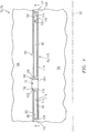
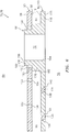
FIG. 4 is a side sectional illustration of an exemplary downstream portion of one of thecombustor walls FIG. 5 is a circumferential sectional illustration of a portion of thecombustor wall FIG. 4 .FIG. 6 is a detailed side sectional illustration of a portion of thecombustor wall FIG. 4 .FIG. 7 is a detailed circumferential illustration of a portion of thecombustor wall FIG. 6 . It should be noted that some details of thecombustor wall FIGS. 6 and7 are not shown inFIGS. 2 ,4 and5 for ease of illustration. - Referring to
FIGS. 2 and4-7 , eachcombustor wall combustor wall FIGS. 2 and4-7 , for example, includes atubular combustor shell 80 and a tubularcombustor heat shield 82 with one or more cooling cavities 84-86 (e.g., impingement cavities) between theshell 80 and theheat shield 82. Eachcombustor wall aperture bodies 88 are disposed circumferentially around thecenterline 22. Each quenchaperture body 88 partially or completely defines a respective one of the quench apertures 72 (see alsoFIG. 3 ) as described below in further detail. - Referring to
FIG. 2 , theshell 80 extends circumferentially around thecenterline 22. Theshell 80 extends axially along thecenterline 22 between an axialforward end 90 and an axialaft end 92. Theshell 80 is connected to thebulkhead 74 at theforward end 90. Theshell 80 may be connected to astator vane assembly 94 or theHPT section 31A at theaft end 92. - Referring to
FIGS. 4 and6 , theshell 80 has anexterior surface 96, aninterior surface 98, one or more aperture surfaces 100, and one or more aperture surfaces 102. At least a portion of theshell 80 extend vertically (e.g., radially) between theshell exterior surface 96 and the shellinterior surface 98. Theshell exterior surface 96, which may also be referred to as a plenum surface, defines a portion of a boundary of theplenum 64. The shellinterior surface 98, which may also be referred to as a cavity surface, defines a portion of a boundary of one or more of the cavities 84-86 (seeFIG. 2 ). - Referring to
FIG. 6 , the aperture surfaces 100 may be arranged in one or more arrays disposed along thecenterline 22. The aperture surfaces 100 in each array may be arranged circumferentially around thecenterline 22. Each of the aperture surfaces 100 defines acooling aperture 104. This coolingaperture 104 extends vertically (e.g., radially) through theshell 80 from theshell exterior surface 96 to the shellinterior surface 98. The coolingaperture 104 may be configured as an impingement aperture. Eachaperture surface 100 ofFIG. 6 , for example, is configured to direct a jet of cooling air to impinge (e.g., substantially perpendicularly) against theheat shield 82. - The aperture surfaces 102 may be arranged circumferentially around the
centerline 22. Eachaperture surface 102 defines anaperture 106 for receiving a respective one of the quenchaperture bodies 88. Eachaperture 106 extends vertically through theshell 80 from theshell exterior surface 96 to the shellinterior surface 98. - Referring to
FIG. 2 , theheat shield 82 extends circumferentially around thecenterline 22. Theheat shield 82 extends axially along thecenterline 22 between an axial forward end and an axial aft end. The forward end is located at (e.g., on, adjacent or proximate) an interface between thecombustor wall bulkhead 74. The aft end may be located at an interface between thecombustor wall stator vane assembly 94 or theHPT section 31A. - The
heat shield 82 may include one or moreheat shield panels panels centerline 22. Thepanels 108 are disposed circumferentially around thecenterline 22 and form a forward hoop. Thepanels 110 are disposed circumferentially around thecenterline 22 and form an aft hoop. Alternatively, theheat shield 82 may be configured from one or more tubular bodies. - Referring to
FIGS. 4 and5 , each of thepanels 110 has one or moreinterior surfaces exterior surface 116. At least a portion of thepanel 110 extends vertically between theinterior surfaces exterior surface 116. Eachinterior surface 112, which may also be referred to as a cavity surface, defines a portion of a boundary of a respective one of thecooling cavities 85. Eachinterior surface 114, which may also be referred to as a cavity surface, defines a portion of a boundary of a respective one of thecooling cavities 86. Theexterior surface 116, which may also be referred to as a chamber surface, defines a portion of thecombustion chamber 56. - Each
panel 110 includes apanel base 118 and one or more panel rails 120-124. Thepanel base 118 and the panel rails 120 and 122-124 may collectively define theinterior surface 112. Thepanel base 118 and the panel rails 121-124 may collectively define theinterior surface 114. Thepanel base 118 may define theexterior surface 116. - The
panel base 118 may be configured as a generally curved (e.g., arcuate) plate. Thepanel base 118 extends axially between an axialforward end 126 and an axialaft end 128. Thepanel base 118 extends circumferentially between opposing circumferential ends 130 and 132. - The panel rails may include one or more axial end rails 120 and 121 and one more circumferential end rails 122 and 123. The panel rails may also include at least one axial
intermediate rail 124. Each of the panel rails 120-124 of theinner wall 76 extends radially in from therespective panel base 118; seeFIG. 2 . Each of the panel rails 120-124 of theouter wall 78 extends radially out from therespective panel base 118; seeFIG. 2 . - The axial end and
intermediate rails axial end rail 120 is arranged at (e.g., on, adjacent or proximate) theforward end 126. Theaxial end rail 121 is arranged at theaft end 128. The axialintermediate rail 124 is disposed axially between the axial end rails 120 and 121, for example, proximate theaft end 128. Thecircumferential end rail 122 is arranged at thecircumferential end 130. Thecircumferential end rail 123 is arranged at thecircumferential end 132. - Referring to
FIGS. 6 and7 , eachpanel 110 may include one ormore effusion apertures 134 and one ormore effusion apertures 136. Theseeffusion apertures panel base 118 to direct cooling air from the coolingcavity 85 into thecombustion chamber 56 to film cool theheat shield 82. Cooling air discharged by one of theeffusion apertures 134 and one of theeffusion apertures 136 forms an air blanket against theexterior surface 116 that flows along a longitudinal path towards a respective one of the quenchapertures 72 as described below in further detail. - Each of the
effusion apertures 134 is defined by one or more aperture surfaces 138 of thepanel base 118. The effusion apertures 134 may be disposed circumferentially around thecenterline 22. Eacheffusion aperture 134, for example, may be generally laterally (e.g., circumferentially) aligned with a respective one of the quench apertures 72. The effusion apertures 134 are also located longitudinally between theeffusion apertures 136 and the quenchapertures 72. Each of theeffusion apertures 134 extend vertically as well as laterally and/or longitudinally (e.g., axially) through thepanel base 118 from an inlet in theinterior surfaces 112 to aneffusion outlet 140 in theexterior surface 116. - Referring to
FIG. 7 , which falls outside the scope of claim 1, theeffusion outlet 140 of eacheffusion aperture 134 may have an elongated cross-section. Eacheffusion outlet 140, for example, may have a longitudinally extending minor axis and a laterally extending major axis. Examples of such elongated cross-sections include, but are not limited to, an elongated polygonal (e.g., rectangular) cross-section, an oval cross-section, an elliptical cross-section, or any other type of elongated cross-section with a minor axis and a major axis. - Each
effusion outlet 140 may have a longitudinal width 142 (e.g., a minor axis width) and a lateral length 144 (e.g., a major axis length). Thelateral length 144 may be more than about three times (3x) greater than thelongitudinal width 142. Thelateral length 144 may also or alternatively be more than about twenty-five percent (25%) of a lateral width 146 (e.g., diameter) of the quenchaperture 72. Thelateral length 144 ofFIG. 7 , for example, is more than about fifty percent (50%) of thelateral width 146. - Referring still to
FIG. 7 , one or more of theeffusion apertures 134 may each be configured as a single cooling slot 148. Eachrespective effusion outlet 140 therefore may be configured as a single slot outlet 150. With this configuration, thelongitudinal width 142 may be measured between opposing longitudinal portions of theaperture surface 138. Thelateral length 144 may be measured between opposing lateral portions of theaperture surface 138. - Alternatively, referring to
FIG. 8 , and in accordance with the invention, one or more of theeffusion apertures 134 are configured from an array of discrete cooling holes 152, where lateral distances betweenadjacent holes 152 in a respective array are less than lateral distances between adjacent arrays (e.g., aperture 134). Eachrespective effusion outlet 140 is therefore configured from an array ofhole outlets 154. With this configuration, thelongitudinal width 142 may be measured between opposing longitudinal portions of (e.g., a central) one of thehole outlets 154; e.g., the longitudinal width is a diameter of thehole outlet 154. Thelateral length 144 may be measured between respective opposing lateral portions of the laterallyperipheral hole outlets 154. - Referring again to
FIGS. 6 and7 , theeffusion outlet 140 of eacheffusion aperture 134 may be located alongitudinal distance 156 from a respective one of the quenchapertures 72 with which it is laterally aligned. Thislongitudinal distance 156 may be equal to between about twenty-five times and about seventy-five times thelongitudinal width 142 of theeffusion outlet 140. With this geometry, cooling air discharged by theeffusion outlet 140 into thecombustion chamber 56 has sufficient space to form at least a portion of the air blanket against theexternal surface 116 as described below in further detail. - The
longitudinal distance 156 may be measured between a lateral centroid of the effusion outlet 140 (e.g., the slot outlet 150 or a central one of the hole outlets 154) and a lateral centroid of an upstream edge of a surface defining a respective one of the quenchaperture 72. Thelongitudinal distance 156 may alternatively correspond to a shortest (e.g., minimum) distance between theeffusion outlet 140 and the quenchaperture 72. - Each of the
effusion apertures 136 is defined by one or more aperture surfaces 158 of thepanel base 118. The effusion apertures 136 may be disposed circumferentially around thecenterline 22. Eacheffusion aperture 136 may be laterally offset from (e.g., misaligned with) a respective one of theeffusion apertures 134. Each of theeffusion apertures 136 extend vertically as well as laterally and/or longitudinally (e.g., axially) through thepanel base 118 from an inlet in theinterior surfaces 112 to aneffusion outlet 160 in theexterior surface 116. - Referring to
FIG. 7 , theeffusion outlet 160 of eacheffusion aperture 136 may have an elongated cross-section. Eacheffusion outlet 160, for example, may have a longitudinally extending minor axis and a laterally extending major axis. Examples of such an elongated cross-section include, but are not limited to, an elongated polygonal (e.g., rectangular) cross-section, an oval cross-section, an elliptical cross-section, or any other type of elongated cross-section with a minor axis and a major axis. - Each
effusion outlet 160 may have a longitudinal width 162 (e.g., a minor axis width) and a lateral length 164 (e.g., a major axis length). Thelateral length 164 may be more than about three times (3x) greater than thelongitudinal width 162. Thelateral length 164 may also or alternatively be more than about twenty-five percent (25%) of thelateral width 146. Thelateral length 164 ofFIG. 7 , for example, is more than about fifty percent (50%) of thelateral width 146 of the quenchaperture 72. The present invention, however, is not limited to the foregoing dimensional relationships. - Referring still to
FIG. 7 , one or more of theeffusion apertures 136 may each be configured as a single cooling slot 166. Eachrespective effusion outlet 160 therefore may be configured as a single slot outlet 168. With this configuration, thelongitudinal width 162 may be measured between opposing longitudinal portions of theaperture surface 158. Thelateral length 164 may be measured between opposing lateral portion of theaperture surface 158. - Alternatively, referring to
FIG. 8 , one or more of theeffusion apertures 136 may each be configured from an array of discrete cooling holes 170. Eachrespective effusion outlet 160 therefore may be configured from an array ofhole outlets 172. With this configuration, thelongitudinal width 162 may be measured between opposing longitudinal portions of (e.g., a central) one of thehole outlets 172; e.g., thelongitudinal width 162 is a diameter of thehole outlet 172. Thelateral length 164 may be measured between respective opposing lateral portions of the laterallyperipheral hole outlets 172. - Referring again to
FIGS. 6 and7 , theeffusion outlet 160 of eacheffusion aperture 136 may be located alongitudinal distance 174 from a respective one of theeffusion apertures 134 with which it forms the air blanket. Thislongitudinal distance 174 may be equal to between about twenty-five times and about seventy-five times thelongitudinal width 162 of theeffusion outlet 160. With this geometry, cooling air discharged by theeffusion outlet 160 into thecombustion chamber 56 may have sufficient space to form at least a portion of the air blanket against theexternal surface 116 as described below in further detail. - The
longitudinal distance 174 may be measured between a lateral centroid of the effusion outlet 160 (e.g., the slot outlet or a central one of the hole outlets) and the lateral centroid of therespective effusion outlet 140. Thelongitudinal distance 174 may alternatively correspond to a shortest (e.g., minimum) distance between theeffusion outlet 160 and therespective effusion outlet 140. - Referring to
FIGS. 4-6 , each of the quenchaperture bodies 88 is formed integral with (or attached to) a respective one of the panel bases 118. One or more of the quenchaperture bodies 88 are located laterally within and extend vertically through a respective one of thecooling cavities 85. One or more of the quenchaperture bodies 88, for example, may be arranged circumferentially between the circumferential end rails 122 and 123 of a respective one of thepanels 110. One or more of the quenchaperture bodies 88 may be arranged axially between the axial end andintermediate rails panels 110. - Referring to
FIG. 6 , each quenchaperture body 88 may include anannular land 176 and anannular rim 178. Theland 176 is connected to therespective panel base 118. Theland 176 extends vertically from thepanel base 118 to a distalland end surface 180. Theland 176 extends laterally between a landouter surface 182 and a bodyinner surface 184, which at least partially defines a respective one of the quenchapertures 72 in thecombustor wall inner surface 184, for example, defines a through-hole that extends vertically through thepanel 110 from a distalrim end surface 186 to theexterior surface 116. - The
rim 178 is connected to theland 176. Therim 178 extends vertically from theland 176 and theland end surface 180 to therim end surface 186. Therim 178 extends laterally between a rimouter surface 188 and the bodyinner surface 184. - Referring to
FIG. 2 , theheat shield 82 of theinner wall 76 circumscribes theshell 80 of theinner wall 76, and defines an inner side of thecombustion chamber 56. Theheat shield 82 of theouter wall 78 is arranged radially within theshell 80 of theouter wall 78, and defines an outer side of thecombustion chamber 56 that is opposite the inner side. - Referring now to
FIG. 6 , each quenchaperture body 88 is (e.g., axially and circumferentially) aligned and mated with a respective one of theapertures 106. Eachrim 178, for example, extends vertically through (or into) a respective one of theapertures 106. Eachland end surface 180 may engage (e.g., slidably contact) and form a seal with the shellinterior surface 98 and, thus, theshell 80. - Referring to
FIG. 2 , theheat shield 82 and, more particularly, each of thepanels shell 80 by a plurality ofmechanical attachments 190; e.g., threaded studs respectively mated with washers and nuts. Theshell 80 and theheat shield 82 thereby respectively form the cooling cavities 84-86 in eachcombustor wall - Referring to
FIGS. 4-6 , each coolingcavity 85 is defined and extends vertically between theinterior surface 98 and a respective one of theinterior surfaces 112 as set forth above. Each coolingcavity 85 is defined and extends circumferentially between the circumferential end rails 122 and 123 of a respective one of thepanels 110. Each coolingcavity 85 is defined and extends axially between the axial end andintermediate rails panels 110. In this manner, each coolingcavity 85 may fluidly couple one or more of the coolingapertures 104 in theshell 80 with one or more of theeffusion apertures heat shield 82. - During turbine engine operation, core air from the
plenum 64 is directed into each coolingcavity 85 throughrespective cooling apertures 104. This core air (e.g., cooling air) may impinge against therespective panel base 118, thereby impingement cooling thepanel 110 and theheat shield 82. The cooling air within each coolingcavity 85 is subsequently directed through theeffusion apertures combustion chamber 56 to film cool a downstream portion of theheat shield 82. Within eacheffusion aperture heat shield 82 through convective heat transfer. - As set forth above, the cooling air discharged from the
effusion apertures exterior surface 116 that flow along respective longitudinal paths towards the quench apertures 72. These air blankets provide thermal barriers between portions of theheat shield 82 adjacent the quenchapertures 72 and the relatively hot core air within thecombustion chamber 56. The air blankets may also or alternatively convectively cool the respective portions of theheat shield 82. - It is worth noting that increasing the
longitudinal distances 156 and/or 174 may result in the cooling air detaching from theexterior surface 116 before cooling the portions of theheat shield 82 adjacent the quenchapertures 72. Conversely, decreasing thelongitudinal distances 156 and/or 174 may not provide enough space for the cooling air to form the air blankets, which may allow secondary horse-shoe vortices in the core air to reach and thermally degrade theheat shield 82. In addition, by superimposing theeffusion outlets 140 with theeffusion outlets 160, the cross-sectional area of theeffusion outlets 140 may be decreased and less core air may be siphoned away from theplenum 64 and directed into thecombustion chamber 56 for cooling purposes. This in turn may increase turbine engine efficiency as well as reduce turbine engine emissions. - In some embodiments, referring to
FIGS. 7 and8 , aportion 192 of theheat shield 82 extending between eacheffusion outlet 140 and the respective quenchaperture 72 may be non-perforated. Aportion 194 of theheat shield 82 extending betweenrespective effusion outlets 140 may also or alternatively be non-perforated. Aportion 196 of theheat shield 82 betweenadjacent effusion apertures portion 198 of theheat shield 82 betweenadjacent effusion apertures 160 may also or alternatively be non-perforated. - In some embodiments, referring to
FIG. 9 (which falls outside the scope of claim 1), one or more of theeffusion outlets 140 and/or 160 may be longitudinally skewed. Eacheffusion outlet 140, for example, may extend laterally between opposing ends 200 and 202. Theeffusion outlet end 200 may be positioned longitudinally closer to a respective one of the quenchapertures 72 than theeffusion outlet end 202. - In some embodiments, referring to
FIGS. 10 and11 , one or more of the effusion outlets 140 (and/or 160) may be vertically recessed from theexterior surface 116. Eachpanel base 118, for example, may include one ormore surfaces recess 208 in thepanel 110. Eacheffusion outlet 140 may be defined at an intersection between the recess surfaces 204 and 206. Alternatively, eacheffusion outlet 140 may be disposed in one of the recess surfaces 204 or 206. Such arecess 208 may promote adhesion of the cooling air discharged from theeffusion outlet 140 against theheat shield 82. In addition, referring toFIG. 11 , thepanel base 118 may be configured to sub-divide thecooling cavity 85 intoseparate cooling cavities panel base 118 ofFIG. 11 , for example, vertically engages theshell 80 proximate therecess 208. - In some embodiments, referring to
FIGS. 6 and7 , each of thesurfaces surfaces centerline 22. - The terms "forward", "aft", "inner", "outer", "radial", circumferential" and "axial" are used to orientate the components of the
turbine engine assembly 60 and thecombustor 62 described above relative to theturbine engine 20 and itscenterline 22. One or more of these turbine engine components, however, may be utilized in other orientations than those described above. The present invention therefore is not limited to any particular spatial orientations. - The
turbine engine assembly 60 may be included in various turbine engines other than the one described above. Theturbine engine assembly 60, for example, may be included in a geared turbine engine where a gear train connects one or more shafts to one or more rotors in a fan section, a compressor section and/or any other engine section. Alternatively, theturbine engine assembly 60 may be included in a turbine engine configured without a gear train. Theturbine engine assembly 60 may be included in a geared or non-geared turbine engine configured with a single spool, with two spools (e.g., seeFIG. 1 ), or with more than two spools. The turbine engine may be configured as a turbofan engine, a turbojet engine, a propfan engine, or any other type of turbine engine. The present invention therefore is not limited to any particular types or configurations of turbine engines. - While various embodiments of the present invention have been disclosed, it will be apparent to those of ordinary skill in the art that many more embodiments and implementations are possible within the scope of the invention. For example, the present invention as described herein includes several aspects and embodiments that include particular features. Although these features may be described individually, it is within the scope of the present invention that some or all of these features may be combined within any one of the aspects and remain within the scope of the invention. Accordingly, the present invention is not to be restricted except in light of the attached claims.
Claims (9)
- An assembly (60) for a turbine engine (20), the assembly comprising:a combustor wall (76, 78) including a shell (80) and a heat shield (82) and defining a quench aperture (72) through the shell (80) and the heat shield (82), the heat shield (82) defining an effusion outlet (140) and a second effusion outlet (140) that is laterally adjacent the effusion outlet (140), the effusion outlet (140) a longitudinal distance (156) from the quench aperture (72) equal to between twenty-five and seventy-five times a width of the effusion outlet (140) and configured such that cooling air discharged from the effusion outlet (140) forms an air blanket that flows along a longitudinal path towards the quench aperture (72),wherein the effusion outlet (140) is configured from a plurality of hole outlets (154) of a respective array of discrete cooling holes (152) defined in the heat shield (82);characterised in that:
a lateral distance between adjacent holes (152) in the respective array forming the effusion outlet (140) is less than a lateral distance between the effusion outlet (140) and the second effusion outlet (140). - The assembly of claim 1, wherein the effusion outlet (140) comprises a longitudinally extending minor axis and a laterally extending major axis.
- The assembly of claim 1 or 2, wherein the longitudinal distance is measured between a lateral centroid of the effusion outlet (140) and a lateral centroid of an upstream edge of a surface defining the quench aperture (72) in the heat shield (82).
- The assembly of claim 1, 2 or 3, wherein the longitudinal distance is the shortest distance between the effusion outlet (140) and the quench aperture (72).
- The assembly of any preceding claim, wherein the width of the effusion outlet (140) is a longitudinal width (142) measured between opposing longitudinal portions of one of the hole outlets (154).
- The assembly of claim 5, wherein the longitudinal width (142) is measured between opposing longitudinal portions of a central one of the hole outlets (154).
- The assembly of claim 5 or 6, wherein the longitudinal width (142) is a diameter of one of the hole outlets (154).
- The assembly of claim 5, 6 or 7, wherein the effusion outlet (140) has a lateral length (144) measured between respective opposing lateral portions of laterally peripheral ones of the hole outlets (154).
- The assembly of claim 8, wherein the lateral length (144) is more than three times greater than the longitudinal width (142).
Applications Claiming Priority (2)
| Application Number | Priority Date | Filing Date | Title |
|---|---|---|---|
| US201361912976P | 2013-12-06 | 2013-12-06 | |
| PCT/US2014/068602 WO2015085081A1 (en) | 2013-12-06 | 2014-12-04 | Cooling a combustor heat shield proximate a quench aperture |
Publications (3)
| Publication Number | Publication Date |
|---|---|
| EP3077726A1 EP3077726A1 (en) | 2016-10-12 |
| EP3077726A4 EP3077726A4 (en) | 2017-04-12 |
| EP3077726B1 true EP3077726B1 (en) | 2021-03-03 |
Family
ID=53274123
Family Applications (1)
| Application Number | Title | Priority Date | Filing Date |
|---|---|---|---|
| EP14867256.1A Active EP3077726B1 (en) | 2013-12-06 | 2014-12-04 | Cooling a combustor heat shield proximate a quench aperture |
Country Status (3)
| Country | Link |
|---|---|
| US (1) | US10697636B2 (en) |
| EP (1) | EP3077726B1 (en) |
| WO (1) | WO2015085081A1 (en) |
Families Citing this family (3)
| Publication number | Priority date | Publication date | Assignee | Title |
|---|---|---|---|---|
| US10816202B2 (en) * | 2017-11-28 | 2020-10-27 | General Electric Company | Combustor liner for a gas turbine engine and an associated method thereof |
| US20230144971A1 (en) * | 2021-11-11 | 2023-05-11 | General Electric Company | Combustion liner |
| EP4202301A1 (en) * | 2021-12-21 | 2023-06-28 | General Electric Company | Combustor with dilution openings |
Citations (1)
| Publication number | Priority date | Publication date | Assignee | Title |
|---|---|---|---|---|
| EP1001222A2 (en) * | 1998-11-13 | 2000-05-17 | General Electric Company | Multi-hole film cooled combustor liner |
Family Cites Families (25)
| Publication number | Priority date | Publication date | Assignee | Title |
|---|---|---|---|---|
| US3623711A (en) * | 1970-07-13 | 1971-11-30 | Avco Corp | Combustor liner cooling arrangement |
| US4265085A (en) | 1979-05-30 | 1981-05-05 | United Technologies Corporation | Radially staged low emission can-annular combustor |
| JPH0660740B2 (en) | 1985-04-05 | 1994-08-10 | 工業技術院長 | Gas turbine combustor |
| JPS6315011A (en) * | 1986-07-08 | 1988-01-22 | Toshiba Corp | Cooling wall structure for gas turbine |
| US5241827A (en) * | 1991-05-03 | 1993-09-07 | General Electric Company | Multi-hole film cooled combuster linear with differential cooling |
| US5461866A (en) | 1994-12-15 | 1995-10-31 | United Technologies Corporation | Gas turbine engine combustion liner float wall cooling arrangement |
| US5758503A (en) | 1995-05-03 | 1998-06-02 | United Technologies Corporation | Gas turbine combustor |
| US6145319A (en) * | 1998-07-16 | 2000-11-14 | General Electric Company | Transitional multihole combustion liner |
| US6408629B1 (en) * | 2000-10-03 | 2002-06-25 | General Electric Company | Combustor liner having preferentially angled cooling holes |
| US6513331B1 (en) * | 2001-08-21 | 2003-02-04 | General Electric Company | Preferential multihole combustor liner |
| US7086232B2 (en) * | 2002-04-29 | 2006-08-08 | General Electric Company | Multihole patch for combustor liner of a gas turbine engine |
| JP4068432B2 (en) * | 2002-11-07 | 2008-03-26 | 株式会社日立製作所 | Gas turbine combustor |
| US7146815B2 (en) | 2003-07-31 | 2006-12-12 | United Technologies Corporation | Combustor |
| US7093441B2 (en) | 2003-10-09 | 2006-08-22 | United Technologies Corporation | Gas turbine annular combustor having a first converging volume and a second converging volume, converging less gradually than the first converging volume |
| US7614235B2 (en) * | 2005-03-01 | 2009-11-10 | United Technologies Corporation | Combustor cooling hole pattern |
| US7546737B2 (en) * | 2006-01-24 | 2009-06-16 | Honeywell International Inc. | Segmented effusion cooled gas turbine engine combustor |
| US7905094B2 (en) * | 2007-09-28 | 2011-03-15 | Honeywell International Inc. | Combustor systems with liners having improved cooling hole patterns |
| US8161752B2 (en) | 2008-11-20 | 2012-04-24 | Honeywell International Inc. | Combustors with inserts between dual wall liners |
| US8910481B2 (en) | 2009-05-15 | 2014-12-16 | United Technologies Corporation | Advanced quench pattern combustor |
| GB0912715D0 (en) | 2009-07-22 | 2009-08-26 | Rolls Royce Plc | Cooling arrangement |
| US9897320B2 (en) * | 2009-07-30 | 2018-02-20 | Honeywell International Inc. | Effusion cooled dual wall gas turbine combustors |
| US8739546B2 (en) * | 2009-08-31 | 2014-06-03 | United Technologies Corporation | Gas turbine combustor with quench wake control |
| US8443610B2 (en) | 2009-11-25 | 2013-05-21 | United Technologies Corporation | Low emission gas turbine combustor |
| US9068751B2 (en) | 2010-01-29 | 2015-06-30 | United Technologies Corporation | Gas turbine combustor with staged combustion |
| WO2015117137A1 (en) * | 2014-02-03 | 2015-08-06 | United Technologies Corporation | Film cooling a combustor wall of a turbine engine |
-
2014
- 2014-12-04 EP EP14867256.1A patent/EP3077726B1/en active Active
- 2014-12-04 WO PCT/US2014/068602 patent/WO2015085081A1/en active Application Filing
- 2014-12-04 US US15/100,374 patent/US10697636B2/en active Active
Patent Citations (1)
| Publication number | Priority date | Publication date | Assignee | Title |
|---|---|---|---|---|
| EP1001222A2 (en) * | 1998-11-13 | 2000-05-17 | General Electric Company | Multi-hole film cooled combustor liner |
Also Published As
| Publication number | Publication date |
|---|---|
| US10697636B2 (en) | 2020-06-30 |
| EP3077726A4 (en) | 2017-04-12 |
| EP3077726A1 (en) | 2016-10-12 |
| WO2015085081A1 (en) | 2015-06-11 |
| US20160298843A1 (en) | 2016-10-13 |
Similar Documents
| Publication | Publication Date | Title |
|---|---|---|
| EP3077727B1 (en) | An assembly for a turbine engine | |
| EP3077641B1 (en) | Cooling an igniter aperture body of a combustor wall | |
| EP3084304B1 (en) | Cooling an aperture body of a combustor wall | |
| EP3102884B1 (en) | Stepped heat shield for a turbine engine combustor | |
| EP3077724B1 (en) | Cooling a quench aperture body of a combustor wall | |
| EP3018418B1 (en) | Combustor wall with aperture body with cooling circuit | |
| US11320146B2 (en) | Film cooling a combustor wall of a turbine engine | |
| EP3967854B1 (en) | Assembly for a turbine engine | |
| US11193672B2 (en) | Combustor quench aperture cooling | |
| EP3066387B1 (en) | Assembly for a turbine engine with acombustor comprising a quench air aperture | |
| EP3077726B1 (en) | Cooling a combustor heat shield proximate a quench aperture |
Legal Events
| Date | Code | Title | Description |
|---|---|---|---|
| PUAI | Public reference made under article 153(3) epc to a published international application that has entered the european phase |
Free format text: ORIGINAL CODE: 0009012 |
|
| 17P | Request for examination filed |
Effective date: 20160706 |
|
| AK | Designated contracting states |
Kind code of ref document: A1 Designated state(s): AL AT BE BG CH CY CZ DE DK EE ES FI FR GB GR HR HU IE IS IT LI LT LU LV MC MK MT NL NO PL PT RO RS SE SI SK SM TR |
|
| AX | Request for extension of the european patent |
Extension state: BA ME |
|
| RAP1 | Party data changed (applicant data changed or rights of an application transferred) |
Owner name: UNITED TECHNOLOGIES CORPORATION |
|
| RIN1 | Information on inventor provided before grant (corrected) |
Inventor name: KOSTKA, JR., STANISLAV Inventor name: CUNHA, FRANK J. Inventor name: MCKINNEY, RANDAL G. |
|
| RIC1 | Information provided on ipc code assigned before grant |
Ipc: F23R 3/06 20060101AFI20161205BHEP |
|
| DAX | Request for extension of the european patent (deleted) | ||
| A4 | Supplementary search report drawn up and despatched |
Effective date: 20170315 |
|
| RIC1 | Information provided on ipc code assigned before grant |
Ipc: F23R 3/06 20060101AFI20170309BHEP |
|
| STAA | Information on the status of an ep patent application or granted ep patent |
Free format text: STATUS: EXAMINATION IS IN PROGRESS |
|
| 17Q | First examination report despatched |
Effective date: 20180727 |
|
| GRAP | Despatch of communication of intention to grant a patent |
Free format text: ORIGINAL CODE: EPIDOSNIGR1 |
|
| STAA | Information on the status of an ep patent application or granted ep patent |
Free format text: STATUS: GRANT OF PATENT IS INTENDED |
|
| INTG | Intention to grant announced |
Effective date: 20200921 |
|
| GRAS | Grant fee paid |
Free format text: ORIGINAL CODE: EPIDOSNIGR3 |
|
| STAA | Information on the status of an ep patent application or granted ep patent |
Free format text: STATUS: GRANT OF PATENT IS INTENDED |
|
| GRAA | (expected) grant |
Free format text: ORIGINAL CODE: 0009210 |
|
| STAA | Information on the status of an ep patent application or granted ep patent |
Free format text: STATUS: THE PATENT HAS BEEN GRANTED |
|
| AK | Designated contracting states |
Kind code of ref document: B1 Designated state(s): AL AT BE BG CH CY CZ DE DK EE ES FI FR GB GR HR HU IE IS IT LI LT LU LV MC MK MT NL NO PL PT RO RS SE SI SK SM TR |
|
| REG | Reference to a national code |
Ref country code: GB Ref legal event code: FG4D |
|
| REG | Reference to a national code |
Ref country code: DE Ref legal event code: R081 Ref document number: 602014075446 Country of ref document: DE Owner name: RAYTHEON TECHNOLOGIES CORPORATION, FARMINGTON, US Free format text: FORMER OWNER: UNITED TECHNOLOGIES CORPORATION, FARMINGTON, CONN., US |
|
| REG | Reference to a national code |
Ref country code: AT Ref legal event code: REF Ref document number: 1367624 Country of ref document: AT Kind code of ref document: T Effective date: 20210315 Ref country code: CH Ref legal event code: EP |
|
| REG | Reference to a national code |
Ref country code: DE Ref legal event code: R096 Ref document number: 602014075446 Country of ref document: DE |
|
| RAP2 | Party data changed (patent owner data changed or rights of a patent transferred) |
Owner name: RAYTHEON TECHNOLOGIES CORPORATION |
|
| REG | Reference to a national code |
Ref country code: IE Ref legal event code: FG4D |
|
| REG | Reference to a national code |
Ref country code: LT Ref legal event code: MG9D |
|
| PG25 | Lapsed in a contracting state [announced via postgrant information from national office to epo] |
Ref country code: BG Free format text: LAPSE BECAUSE OF FAILURE TO SUBMIT A TRANSLATION OF THE DESCRIPTION OR TO PAY THE FEE WITHIN THE PRESCRIBED TIME-LIMIT Effective date: 20210603 Ref country code: NO Free format text: LAPSE BECAUSE OF FAILURE TO SUBMIT A TRANSLATION OF THE DESCRIPTION OR TO PAY THE FEE WITHIN THE PRESCRIBED TIME-LIMIT Effective date: 20210603 Ref country code: HR Free format text: LAPSE BECAUSE OF FAILURE TO SUBMIT A TRANSLATION OF THE DESCRIPTION OR TO PAY THE FEE WITHIN THE PRESCRIBED TIME-LIMIT Effective date: 20210303 Ref country code: FI Free format text: LAPSE BECAUSE OF FAILURE TO SUBMIT A TRANSLATION OF THE DESCRIPTION OR TO PAY THE FEE WITHIN THE PRESCRIBED TIME-LIMIT Effective date: 20210303 Ref country code: GR Free format text: LAPSE BECAUSE OF FAILURE TO SUBMIT A TRANSLATION OF THE DESCRIPTION OR TO PAY THE FEE WITHIN THE PRESCRIBED TIME-LIMIT Effective date: 20210604 Ref country code: LT Free format text: LAPSE BECAUSE OF FAILURE TO SUBMIT A TRANSLATION OF THE DESCRIPTION OR TO PAY THE FEE WITHIN THE PRESCRIBED TIME-LIMIT Effective date: 20210303 |
|
| REG | Reference to a national code |
Ref country code: NL Ref legal event code: MP Effective date: 20210303 |
|
| REG | Reference to a national code |
Ref country code: AT Ref legal event code: MK05 Ref document number: 1367624 Country of ref document: AT Kind code of ref document: T Effective date: 20210303 |
|
| PG25 | Lapsed in a contracting state [announced via postgrant information from national office to epo] |
Ref country code: LV Free format text: LAPSE BECAUSE OF FAILURE TO SUBMIT A TRANSLATION OF THE DESCRIPTION OR TO PAY THE FEE WITHIN THE PRESCRIBED TIME-LIMIT Effective date: 20210303 Ref country code: PL Free format text: LAPSE BECAUSE OF FAILURE TO SUBMIT A TRANSLATION OF THE DESCRIPTION OR TO PAY THE FEE WITHIN THE PRESCRIBED TIME-LIMIT Effective date: 20210303 Ref country code: RS Free format text: LAPSE BECAUSE OF FAILURE TO SUBMIT A TRANSLATION OF THE DESCRIPTION OR TO PAY THE FEE WITHIN THE PRESCRIBED TIME-LIMIT Effective date: 20210303 Ref country code: SE Free format text: LAPSE BECAUSE OF FAILURE TO SUBMIT A TRANSLATION OF THE DESCRIPTION OR TO PAY THE FEE WITHIN THE PRESCRIBED TIME-LIMIT Effective date: 20210303 |
|
| PG25 | Lapsed in a contracting state [announced via postgrant information from national office to epo] |
Ref country code: NL Free format text: LAPSE BECAUSE OF FAILURE TO SUBMIT A TRANSLATION OF THE DESCRIPTION OR TO PAY THE FEE WITHIN THE PRESCRIBED TIME-LIMIT Effective date: 20210303 |
|
| PG25 | Lapsed in a contracting state [announced via postgrant information from national office to epo] |
Ref country code: AT Free format text: LAPSE BECAUSE OF FAILURE TO SUBMIT A TRANSLATION OF THE DESCRIPTION OR TO PAY THE FEE WITHIN THE PRESCRIBED TIME-LIMIT Effective date: 20210303 Ref country code: EE Free format text: LAPSE BECAUSE OF FAILURE TO SUBMIT A TRANSLATION OF THE DESCRIPTION OR TO PAY THE FEE WITHIN THE PRESCRIBED TIME-LIMIT Effective date: 20210303 Ref country code: CZ Free format text: LAPSE BECAUSE OF FAILURE TO SUBMIT A TRANSLATION OF THE DESCRIPTION OR TO PAY THE FEE WITHIN THE PRESCRIBED TIME-LIMIT Effective date: 20210303 Ref country code: SM Free format text: LAPSE BECAUSE OF FAILURE TO SUBMIT A TRANSLATION OF THE DESCRIPTION OR TO PAY THE FEE WITHIN THE PRESCRIBED TIME-LIMIT Effective date: 20210303 |
|
| PG25 | Lapsed in a contracting state [announced via postgrant information from national office to epo] |
Ref country code: IS Free format text: LAPSE BECAUSE OF FAILURE TO SUBMIT A TRANSLATION OF THE DESCRIPTION OR TO PAY THE FEE WITHIN THE PRESCRIBED TIME-LIMIT Effective date: 20210703 Ref country code: SK Free format text: LAPSE BECAUSE OF FAILURE TO SUBMIT A TRANSLATION OF THE DESCRIPTION OR TO PAY THE FEE WITHIN THE PRESCRIBED TIME-LIMIT Effective date: 20210303 Ref country code: RO Free format text: LAPSE BECAUSE OF FAILURE TO SUBMIT A TRANSLATION OF THE DESCRIPTION OR TO PAY THE FEE WITHIN THE PRESCRIBED TIME-LIMIT Effective date: 20210303 Ref country code: PT Free format text: LAPSE BECAUSE OF FAILURE TO SUBMIT A TRANSLATION OF THE DESCRIPTION OR TO PAY THE FEE WITHIN THE PRESCRIBED TIME-LIMIT Effective date: 20210705 Ref country code: ES Free format text: LAPSE BECAUSE OF FAILURE TO SUBMIT A TRANSLATION OF THE DESCRIPTION OR TO PAY THE FEE WITHIN THE PRESCRIBED TIME-LIMIT Effective date: 20210303 |
|
| REG | Reference to a national code |
Ref country code: DE Ref legal event code: R097 Ref document number: 602014075446 Country of ref document: DE |
|
| PLBE | No opposition filed within time limit |
Free format text: ORIGINAL CODE: 0009261 |
|
| STAA | Information on the status of an ep patent application or granted ep patent |
Free format text: STATUS: NO OPPOSITION FILED WITHIN TIME LIMIT |
|
| PG25 | Lapsed in a contracting state [announced via postgrant information from national office to epo] |
Ref country code: DK Free format text: LAPSE BECAUSE OF FAILURE TO SUBMIT A TRANSLATION OF THE DESCRIPTION OR TO PAY THE FEE WITHIN THE PRESCRIBED TIME-LIMIT Effective date: 20210303 Ref country code: AL Free format text: LAPSE BECAUSE OF FAILURE TO SUBMIT A TRANSLATION OF THE DESCRIPTION OR TO PAY THE FEE WITHIN THE PRESCRIBED TIME-LIMIT Effective date: 20210303 |
|
| 26N | No opposition filed |
Effective date: 20211206 |
|
| PG25 | Lapsed in a contracting state [announced via postgrant information from national office to epo] |
Ref country code: SI Free format text: LAPSE BECAUSE OF FAILURE TO SUBMIT A TRANSLATION OF THE DESCRIPTION OR TO PAY THE FEE WITHIN THE PRESCRIBED TIME-LIMIT Effective date: 20210303 |
|
| PG25 | Lapsed in a contracting state [announced via postgrant information from national office to epo] |
Ref country code: IT Free format text: LAPSE BECAUSE OF FAILURE TO SUBMIT A TRANSLATION OF THE DESCRIPTION OR TO PAY THE FEE WITHIN THE PRESCRIBED TIME-LIMIT Effective date: 20210303 |
|
| PG25 | Lapsed in a contracting state [announced via postgrant information from national office to epo] |
Ref country code: IS Free format text: LAPSE BECAUSE OF FAILURE TO SUBMIT A TRANSLATION OF THE DESCRIPTION OR TO PAY THE FEE WITHIN THE PRESCRIBED TIME-LIMIT Effective date: 20210703 |
|
| PG25 | Lapsed in a contracting state [announced via postgrant information from national office to epo] |
Ref country code: MC Free format text: LAPSE BECAUSE OF FAILURE TO SUBMIT A TRANSLATION OF THE DESCRIPTION OR TO PAY THE FEE WITHIN THE PRESCRIBED TIME-LIMIT Effective date: 20210303 |
|
| REG | Reference to a national code |
Ref country code: CH Ref legal event code: PL |
|
| REG | Reference to a national code |
Ref country code: BE Ref legal event code: MM Effective date: 20211231 |
|
| PG25 | Lapsed in a contracting state [announced via postgrant information from national office to epo] |
Ref country code: LU Free format text: LAPSE BECAUSE OF NON-PAYMENT OF DUE FEES Effective date: 20211204 Ref country code: IE Free format text: LAPSE BECAUSE OF NON-PAYMENT OF DUE FEES Effective date: 20211204 |
|
| PG25 | Lapsed in a contracting state [announced via postgrant information from national office to epo] |
Ref country code: BE Free format text: LAPSE BECAUSE OF NON-PAYMENT OF DUE FEES Effective date: 20211231 |
|
| PG25 | Lapsed in a contracting state [announced via postgrant information from national office to epo] |
Ref country code: LI Free format text: LAPSE BECAUSE OF NON-PAYMENT OF DUE FEES Effective date: 20211231 Ref country code: CH Free format text: LAPSE BECAUSE OF NON-PAYMENT OF DUE FEES Effective date: 20211231 |
|
| PG25 | Lapsed in a contracting state [announced via postgrant information from national office to epo] |
Ref country code: HU Free format text: LAPSE BECAUSE OF FAILURE TO SUBMIT A TRANSLATION OF THE DESCRIPTION OR TO PAY THE FEE WITHIN THE PRESCRIBED TIME-LIMIT; INVALID AB INITIO Effective date: 20141204 |
|
| P01 | Opt-out of the competence of the unified patent court (upc) registered |
Effective date: 20230520 |
|
| PG25 | Lapsed in a contracting state [announced via postgrant information from national office to epo] |
Ref country code: CY Free format text: LAPSE BECAUSE OF FAILURE TO SUBMIT A TRANSLATION OF THE DESCRIPTION OR TO PAY THE FEE WITHIN THE PRESCRIBED TIME-LIMIT Effective date: 20210303 |
|
| PGFP | Annual fee paid to national office [announced via postgrant information from national office to epo] |
Ref country code: GB Payment date: 20231121 Year of fee payment: 10 |
|
| PGFP | Annual fee paid to national office [announced via postgrant information from national office to epo] |
Ref country code: FR Payment date: 20231122 Year of fee payment: 10 Ref country code: DE Payment date: 20231121 Year of fee payment: 10 |
|
| PG25 | Lapsed in a contracting state [announced via postgrant information from national office to epo] |
Ref country code: MK Free format text: LAPSE BECAUSE OF FAILURE TO SUBMIT A TRANSLATION OF THE DESCRIPTION OR TO PAY THE FEE WITHIN THE PRESCRIBED TIME-LIMIT Effective date: 20210303 |
|
| PG25 | Lapsed in a contracting state [announced via postgrant information from national office to epo] |
Ref country code: TR Free format text: LAPSE BECAUSE OF FAILURE TO SUBMIT A TRANSLATION OF THE DESCRIPTION OR TO PAY THE FEE WITHIN THE PRESCRIBED TIME-LIMIT Effective date: 20210303 |
|
| PG25 | Lapsed in a contracting state [announced via postgrant information from national office to epo] |
Ref country code: MT Free format text: LAPSE BECAUSE OF FAILURE TO SUBMIT A TRANSLATION OF THE DESCRIPTION OR TO PAY THE FEE WITHIN THE PRESCRIBED TIME-LIMIT Effective date: 20210303 |