EP3077604B1 - Method for waterproofing a roof covering - Google Patents
Method for waterproofing a roof covering Download PDFInfo
- Publication number
- EP3077604B1 EP3077604B1 EP14816146.6A EP14816146A EP3077604B1 EP 3077604 B1 EP3077604 B1 EP 3077604B1 EP 14816146 A EP14816146 A EP 14816146A EP 3077604 B1 EP3077604 B1 EP 3077604B1
- Authority
- EP
- European Patent Office
- Prior art keywords
- seams
- bitumen
- membrane
- layer
- overlapping regions
- Prior art date
- Legal status (The legal status is an assumption and is not a legal conclusion. Google has not performed a legal analysis and makes no representation as to the accuracy of the status listed.)
- Not-in-force
Links
Images


Classifications
-
- E—FIXED CONSTRUCTIONS
- E04—BUILDING
- E04D—ROOF COVERINGS; SKY-LIGHTS; GUTTERS; ROOF-WORKING TOOLS
- E04D5/00—Roof covering by making use of flexible material, e.g. supplied in roll form
- E04D5/14—Fastening means therefor
- E04D5/149—Fastening means therefor fastening by welding
-
- E—FIXED CONSTRUCTIONS
- E04—BUILDING
- E04D—ROOF COVERINGS; SKY-LIGHTS; GUTTERS; ROOF-WORKING TOOLS
- E04D11/00—Roof covering, as far as not restricted to features covered by only one of groups E04D1/00 - E04D9/00; Roof covering in ways not provided for by groups E04D1/00 - E04D9/00, e.g. built-up roofs, elevated load-supporting roof coverings
- E04D11/02—Build-up roofs, i.e. consisting of two or more layers bonded together in situ, at least one of the layers being of watertight composition
-
- E—FIXED CONSTRUCTIONS
- E04—BUILDING
- E04D—ROOF COVERINGS; SKY-LIGHTS; GUTTERS; ROOF-WORKING TOOLS
- E04D15/00—Apparatus or tools for roof working
- E04D15/04—Apparatus or tools for roof working for roof coverings comprising slabs, sheets or flexible material
-
- E—FIXED CONSTRUCTIONS
- E04—BUILDING
- E04D—ROOF COVERINGS; SKY-LIGHTS; GUTTERS; ROOF-WORKING TOOLS
- E04D5/00—Roof covering by making use of flexible material, e.g. supplied in roll form
- E04D5/14—Fastening means therefor
- E04D5/141—Fastening means therefor characterised by the location of the fastening means
- E04D5/142—Fastening means therefor characterised by the location of the fastening means along the edge of the flexible material
Definitions
- the invention relates to a method for waterproofing a roof covering.
- a flat roof usually consists of four layers: (starting from the bottom) a vapor barrier, an insulating layer, a bottom layer and a top layer. In this case, the air-tightness (vapor barrier) and the watertightness (bottom and top layer) are of prime concern.
- bituminous membranes are used for this purpose.
- the following classic techniques are used to apply bituminous membranes to flat roofs: Heat-welding - part of the bottom layer of the membrane is melted by means of a torch. After solidifying, this layer bonds to the substrate. No separate finish of the seams is required. Mechanical attachment - the membrane is attached to the substrate by means of screws fitted on the edge of the surface.
- a relatively small torch In order to weld the seams (in the case of mechanical attachment or bonding using cold adhesive), a relatively small torch can be used which is especially designed to be pushed between the ends of the two adjacent membranes.
- these types of roof covering are used when circumstances do not allow heat-welding to be used (e.g. if an insulating layer situated underneath could be damaged by the flame, or if the architect expressly forbids heat-welding for safety reasons).
- a flameless sealing of the seams has to be resorted to.
- the only alternative technique which can be used at present is hot-air welding. Via a flat nozzle which is pushed into a fold between the two membranes, the machine blows hot air into the seam.
- the rear wheel pushes down on the formed weld.
- the self-adhesive membranes have been developed specially for applications in which welding (heat-welding or hot-air welding) is undesirable.
- the adhesive bonds at the seams should in principle be watertight.
- experience shows that, due to capillary forces, moisture can still penetrate through the seams if the water pressure is high. For this reason, they are often only used as bottom layers. If a better (flameless) way could be found to seal the seams, self-adhesive membranes could also be used more frequently as top layers. There is therefore a need for a method which offers an alternative to the existing methods and overcomes one or more of the drawbacks.
- EP 1 130 186 A2 discloses a method, wherein roof membranes are welded by induction heating.
- the membrane comprises a top layer, a reinforcing layer, a metal layer and a bottom layer.
- the metal layer is embedded in the bottom layer.
- the invention and preferred embodiments thereof offer a solution to one or more of the above needs.
- the invention comprises a method for fitting a roof covering according to claims 1 to 15.
- a measurable value such as a parameter, an amount, a time duration, and so on
- a measurable value such as a parameter, an amount, a time duration, and so on
- the value to which the term “approximately” refers has, per se, also been disclosed. Any documents which are cited in the present specification are deemed to have been fully incorporated herein by reference.
- the invention comprises a method according to claim 1 for fitting a roof covering in sections, wherein the roof covering comprises a membrane, wherein the membrane comprises bitumen and a metal, the method comprising the following steps:
- the present method also has the advantage that relatively inaccessible parts (such as corners or edges) can be melted together by hand. As a result thereof, the roofer no longer requires an additional smaller welding apparatus (cf. hot-air and heat-welding).
- the induction generator is provided with a removable part comprising the induction coil, by means of which the relatively inaccessible parts can be finished using a smaller part of the induction generator which can be manipulated by hand during fitting of the roof covering. This will be explained in more detail below.
- bitumen is understood to mean a visco-elastic liquid which forms a natural component of petroleum. After fractional distillation, bitumen can be separated from other constituents of the petroleum, such as naphtha, gasoline or diesel, and remains behind as the heaviest constituent. Bitumen mainly consists of hydrocarbons. It is also possible to use substances of vegetable origin which are similar to bitumen as alternatives. For use in roof covering, bitumen is usually used in a modified form. Modified bitumen consists of bitumen and one or more chemical agents, such as inter alia polymers and additives, such as resins and waxes.
- bitumen modified with styrene butadiene styrene SBS
- bitumen modified with thermoplastic polyolefins TPO
- bitumen modified with atactic polypropylene APP
- seams is understood to mean the gaps between two sections of roof covering. More specifically, the seam is understood to be the location where two sections of material are or will be attached to each other.
- overlapping regions is understood to mean the area in which two sections of roof covering or membranes overlap one another.
- the speed of the generator is regulated based on a measurement of the power, i.e.
- the power provided to the seams and/or overlapping regions via the induction coil will be measured by measuring the power consumed by the induction coil (power output). More particularly, the present inventors have found that in practice, the power provided to the seams and/or overlapping regions can be considered being approximately equal to or a certain fraction of the power consumed by the induction coil.
- the speed may be regulated based on the power provided to the seams, such that the energy density which is provided to the seams and/or overlapping regions is constant, or within a certain predetermined range.
- energy density monitoring refers to the (heat) energy provided per unit of length.
- the power is equal to the (heat) energy per unit of time.
- the speed required for providing a predetermined energy density to the seams and/or overlapping regions can be determined by measuring the power provided to the seams and/or overlapping regions, and dividing the measured power by the predetermined energy density. More particularly, the higher the power output of the induction coil the lower the speed will be, and vice versa.
- the speed of the generator may be regulated (automatically) in order to provide the seams and/or overlapping regions with a predetermined energy density.
- the preferred energy density values can be determined empirically for each membrane type, and may depend of parameters such as membrane thickness, membrane composition, and membrane temperature.
- the speed of the generator is regulated based on a measurement of the temperature of the seams and/or overlapping regions or overlapping membranes which are being heated using the induction generator. More specifically, the speed may be regulated (automatically) such that the temperature of the seams and/or overlapping regions is within a predetermined temperature range. Typically, a higher measured temperature will result in a lower speed. For example, the speed can be increased if the measured temperature is above a first value and decreased if the measured temperature is below a second value, wherein the first value is higher than or identical to the second value.
- the preferred temperature can be determined empirically for each membrane type, and may depend of parameters such as membrane thickness and membrane composition.
- the speed is determined or regulated by a temperature measurement of the bitumen in step (c); and the speed is adjusted so that the temperature is at least 60°C and at most 160°C, preferably at least 61°C and at most 150°C, preferably at least 62°C and at most 140°C, preferably at least 63°C and at most 130°C, preferably at least 64°C and at most 120°C, preferably at least 65°C and at most 110°C, preferably at least 66°C and at most 105°C, preferably at least 67°C and at most 100°C, preferably at least 68°C and at most 95°C, preferably at least 69°C and at most 92°C, preferably at least 70°C and at most 90°C, and preferably approximately 70°C, 75°C, 80°C, 85°C or 90°C.
- the speed of the generator is regulated based on a combination of temperature measurements and power measurements as described above.
- the present inventors have found that when moving the (induction coil of) the generator by hand, e.g. for details which are difficult to access, the best results were obtained when regulating the speed based on a temperature measurement.
- the speed may be regulated based on a temperature measurement when the induction coil is moved manually; and based on a power measurement when the induction coil is moved automatically.
- the speed is at least 1 m/min and at most 15 m/min, preferably at least 2 m/min and at most 10 m/min, preferably at least 3 m/min and at most 7 m/min, and preferably 3 m/min, 3.5 m/min, 4 m/min, 4.5 m/min, 5 m/min, 5.5 m/min, 6 m/min, 6.5 m/min or 7 m/min.
- temperature monitoring and/or energy density monitoring may be used to regulate both the speed and the power of the induction coil. This may allow for a smoother movement of the induction generator.
- the method furthermore comprises the step:
- the one or more seams have a width of at most 5 mm, preferably at most 2.5 mm, preferably at most 1.0 mm, preferably at most 0.5 mm, preferably at most 0.2 mm, preferably at most 0.1 mm.
- a membrane on top of the seam is preferably a membrane identical to the other membranes. Sealing is effected by treating the sealing strip via induction in the way as described herein.
- the membrane used in the method comprises the following layers:
- the membrane may also comprise other layers, such as a finishing layer, a foil/film, a fleece, a web, etc.
- the membrane may, for example, comprise further finishing layers.
- the membrane may comprise a top finishing layer, in which use is made of materials such as sand, slate chippings, granules, stone chippings, anthracite, fleece, etc.
- the membrane may comprise a bottom finishing layer, in which use is made of materials such as sand, slate chippings, granules, stone chippings, anthracite, fleece, etc.
- the top finishing layer and the bottom finishing layer may be the same or different.
- the present inventors have found that an improved adhesion between overlapping membranes can be obtained if the parts of the top coating (i) and bottom coating (iv) which are part of overlapping areas and are to be melted together, are free from finishing layers, in particular finishing layers comprising sand, slate chippings, granules, stone chippings, anthracite, fleece, etc.
- the top coating (i) of the membranes may be provided with a top finishing layer, except for a lateral strip which is free from said finishing layer.
- the strip preferably has a width of at least 5 cm and at most 20 cm, preferably at least 7 cm and at most 14 cm. Most preferably, such strip has a width of approximately 10 cm.
- the lateral strip is typically provided in the longitudinal direction of the membrane as shown in Fig. 3A , but may continue in the transverse direction, as shown in Fig. 3B .
- the bottom coating (iv) of the membranes may be provided with a bottom finishing layer, except for a lateral strip which is free from said finishing layer.
- the strip preferably has a width of at least 5 cm and at most 20 cm, preferably at least 7 cm and at most 14 cm. Most preferably, such strip has a width of approximately 10 cm.
- the lateral strip may be provided in the longitudinal direction only, or continue in the transverse direction.
- the membranes are provided with a top finishing layer and a bottom finishing layer, except for a strip as described above, it is preferred that the strip of the top coating and the strip of the bottom layer are provided on laterally opposed sides of the membrane.
- the strips may be obtained by covering the membrane with a protective foil strip when applying the finishing layer.
- the bottom layer may be provided with an adhesive, more particularly to make the membrane self-adhesive.
- Self-adhesive membranes are currently primarily used as bottom layers, as their seams are typically not sufficiently watertight.
- the present membranes further comprise a metal layer (iii) which allows for inductive heating, the watertightness of the seams can be significantly improved, such that the self-adhesive layers can also be used as top layers.
- the top coating (i) comprises modified bitumen.
- the top coating (i) has a thickness of 0.1 to 5.0 mm.
- the bottom coating (iv) comprises modified bitumen.
- the bottom coating (iv) has a thickness of 0.1 to 5.0 mm.
- the thickness of the top coating (i) may be the same or different from the thickness of the bottom coating (iv).
- the modified bitumen is preferably a mixture of bitumen and plastics, polymers and/or thermoplastic polymers.
- plastics such as chlorosulfonyl polyethylene (CSM), ethylene ethyl acrylate (EEA), ethylene butyl acrylate (EBA), ethylene copolymer bitumen (ECB or EBT), ethylene vinyl acetate (EVAC), flexible polyolefin (FPO or PO-F), flexible polypropylene (FPP or PP-F), polyethylene (PE), chlorinated polyethylene (PE-C), polyisobutylene (PIB), polypropylene (PP) and/or polyvinyl chloride (PVC) are used.
- CSM chlorosulfonyl polyethylene
- ESA ethylene ethyl acrylate
- EBA ethylene butyl acrylate
- EBT ethylene copolymer bitumen
- EVAC ethylene vinyl acetate
- FPO or PO-F flexible polypropylene
- PE polyethylene
- PE-C chlorinated polyethylene
- PIB polyisobutylene
- PP poly
- polymers such as butadiene, chloroprene, chlorosulfonyl polyethylene, terpolymer of ethylene or propylene, isobutene isoprene and/or acrylonitrile butadiene are used.
- thermoplastic polymers such as elastomers, styrene ethylene butylene styrene, crosslinked and non-crosslinked thermoplastic elastomers, styrene butadiene styrene (SBS), styrene isoprene styrene (SIS), thermoplastic polyolefins (TPO) and/or atactic polypropylene (APP) are used.
- bitumen modified with styrene butadiene styrene (SBS), bitumen modified with atactic polypropylene (APP) and/or bitumen modified with thermoplastic polyolefins (TPO) is used.
- SBS styrene butadiene styrene
- APP bitumen modified with atactic polypropylene
- TPO thermoplastic polyolefins
- the top coating (i) and bottom coating (iv) have different compositions. Excellent results can be obtained using materials having a different hardness, more specifically when the top layer is harder than the bottom layer.
- the top coating (i) contains bitumen modified with atactic polypropylene (APP) and/or bitumen modified with thermoplastic polyolefins (TPO) and the bottom coating (iv) contains bitumen modified with styrene butadiene styrene (SBS).
- the top coating (i) may not have a uniform composition. More particularly, the composition of the top coating (i) may vary along the width of the membrane. For example, the top coating (i) may have regions which have essentially the same composition as the bottom coating (iv), and regions which have a different composition than the bottom coating (iv).
- the region having essentially the same composition as the bottom coating (iv) is a strip (9) along a lateral edge of the membrane (1), as shown in Fig. 4 .
- the strip has a width of at least 5 cm and at most 20 cm, preferably at least 7 cm and at most 14 cm, more preferably approximately 10 cm. This ensures that the overlapping regions of the membranes have uniform properties, while still allowing using different compositions for the top coating (i) and bottom coating (iv).
- the composition of the bottom coating (iv) may vary along the width of the membrane.
- the reinforcing layer (ii) comprises polyester, glass, polyester/glass, etc.
- the reinforcing layer ensures that the membrane provides sufficient support and mechanical properties to the membrane. Polyester and polyester/glass composite materials are particularly preferred. The inventors have found that such reinforcing layers result in membranes which are less prone to stretch forces.
- the reinforcing layer (ii) comprises scrim, gauze, fleece, etc, preferably a scrim or gauze such as glass scrim, polyester scrim, polyester/glass scrim, etc.
- the use of glass scrim, polyester scrim and/or polyester/glass scrim in the reinforcing layer; and particularly polyester scrim and/or polyester/glass composite scrim provides the membrane with ideal strength.
- the membrane comprises metal.
- the membrane comprises aluminum, copper, iron, or an alloy such as steel (preferably stainless steel), more preferably the membrane comprises aluminum.
- the metal layer (iii) comprises aluminum, copper, iron, or an alloy such as steel, for example stainless steel.
- the metal layer (iii) comprises aluminum.
- the metal layer (iii) has a thickness of at least 10 ⁇ m and at most 500 ⁇ m, preferably of at least 30 ⁇ m and at most 300 ⁇ m, preferably of at least 40 ⁇ m and at most 200 ⁇ m.
- the metal layer (iii) is present at a weight per unit area of at least 10 g/m 2 and at most 500 g/m 2 , preferably of at least 40 g/m 2 and at most 300 g/m 2 , preferably of at least 60 g/m 2 and at most 200 g/m 2 , preferably of at least 80 g/m 2 and at most 200 g/m 2 , preferably of at least 100 g/m 2 and at most 150 g/m 2 .
- the metal layer (iii) is a partial layer or edge layer which is present at the (lateral and/or transversal) edges of the roof covering, preferably the metal layer is arranged at a distance of at most 20 cm from at least one of the edges of the membrane, preferably at a distance of at most 10 cm, preferably at a distance of at most 5 cm, preferably at a distance from the edge of at most 1 cm, preferably on at least one of the edges of the membrane.
- the provision of the metal layer (iii) as a partial layer or edge layer allows for reducing the material cost for producing the membranes.
- the metal layer (iii) is a partial layer selected from the group comprising: one or more strips, a lattice, or one or more threads.
- the metal layer (iii) is a strip having a width of at least 0.1 cm and at most 110 cm, preferably at least 2 cm and at most 15 cm, preferably at least 4 cm and at most 6 cm, preferably approximately 5 cm. Such a width may ensure optimum heat control. If the strip is too narrow, the bitumen does not heat up to a sufficient degree, while a strip which is too wide may lead to burning through. Whereas the provision of only a lateral edge with a metal layer is quite simple, the provision of a lateral edge and a transversal edge of the membrane is more complex. Therefore, in certain embodiments, the metal layer (iii) may be provided along essentially the entire width and length of the membrane.
- Such metal layer (iii) may be partial layer, e.g. a metal foil provided with perforations.
- the perforations may result in various foil geometries, and may include lattice structures.
- the metal layer (iii) comprises a lattice.
- the use of a metal layer in the form of a lattice ensures uniform heat distribution across the membrane.
- the lattice may be a rectangular or square lattice.
- the metal layer (iii) comprises one or more threads, preferably with the one or more threads running parallel to one another or the one or more threads running perpendicular to one another.
- the membrane has a total thickness of at least 0.5 mm and at most 10.5 mm, preferably of at least 0.5 mm and at most 5 mm; for example about 3 mm.
- the generator comprises means for determining the power provided to the one or more seams and/or overlapping regions. More particularly, the generator may comprise means for determining the power output or power consumed by the induction coil.
- the induction generator comprises a means for temperature monitoring. Typically, the generator will also comprise a computer chip which is provided with software for regulating the speed of the generator based on the measured power and/or temperature.
- the induction generator is limited in weight and size.
- the induction generator weighs at most 30 kg, more preferably at most 25 kg, more preferably at most 20 kg.
- the induction generator is provided with associated air cooling means.
- the induction generator is self-propelled.
- the induction generator is safe and ergonomic.
- the means for temperature monitoring comprises an infrared (IR) sensor, more preferably an IR sensor with laser aligner. An IR sensor allows for determining the temperature of the membrane surface, which is indicative of the internal temperature at the seam or overlapping region.
- the induction generator comprises a location-determining means.
- the location-determining means comprises a GPS, preferably a real-time kinematic GPS.
- the induction generator described herein is provided with one or more induction coils.
- the induction generator comprises two induction coils in line with one another, wherein the induction coils are configured to heat up the metal.
- the induction generator comprises a single induction coil.
- the induction generator comprises a removable part comprising an induction coil. More particularly, the induction generator may be provided on a removable part which is connected to the rest of the induction generator via one or more cables, thereby allowing movement of said removable part with respect to the rest of the induction generator.
- the removable part also comprises the location-determining means.
- the removable part may be used for sealing the cross seams (end seams) and seams on non-horizontal surfaces.
- the removable part is preferably connected to a central part of the induction generator via a power and/or data cable.
- This central part preferably comprises a motor, an induction coil (preferably with a fan for air cooling) and/or a processor.
- the central part preferably comprises an induction coil which is situated closer to the edge of the membrane and causes hot bitumen to flow out. This acts as a visual check for the watertightness.
- the induction generator is manipulated by a roofer by means of an extending and/or adjustable arm, which is optionally provided with an operating display. The electrical power may be provided via the arm.
- the induction generator comprises a pressure-exerting roller.
- the induction generator comprises at least two wheels, with one wheel preferably serving as a pressure-exerting roller. Preferably, this is the largest wheel.
- the induction generator comprises at least three wheels, with one wheel preferably serving as a pressure-exerting roller.
- the induction generator will be provided with an interface which allows for the user to select a predetermined temperature or temperature range which is to be achieved.
- the induction generator will be provided with an interface which allows for the user to select a predetermined energy density or energy density range which is to be achieved.
- Such interface may comprise elements such as knobs, dials, a screen, a touchscreen, and the like.
- the induction generator comprises a U-shaped inductor or a pot-shaped inductor.
- the induction generator comprises a U-shaped inductor. This embodiment makes it possible to transfer more energy to the metal.
- the induction generator has a frequency of at least 10 kHz and at most 400 kHz. The generator will typically move in a direction such that the seams and/or overlapping regions of the membranes are first heated, and then pressed with a pressure-exerting roller.
- the induction coil and pressure-exerting roller may be provided such that their relative position is interchangeable.
- the induction generator may be provided with a handle which can be moved between two positions, more particularly to the front and to the back of the generator. This allows for the user to choose whether to walk behind or in front of the generator, thereby facilitating the use thereof.
- Duo Tack 3 AGR/F C250 was used as membrane. This membrane has a top coating of TPO plastomer bitumen, a reinforcing layer of polyester and glass scrim and a bottom coating of SBS elastomer self-adhesive bitumen. A glass scrim with the aluminum facing downwards was used as reinforcing layer.
- test sections were prepared. After the backing film had been removed, the test sections were placed on top of each other and pressed down using a foot. The test sections, except the reference sections, were made watertight by means of induction, with the speed being varied.
- test sections are additionally pressed down again by running a pressure-exerting roller over them once.
- the machine was passed across the test piece 3 times in succession, after which they were additionally pressed down by running the pressure-exerting roller over them once. The overlap was 10 cm wide.
- test sections were cut into the correct test shape according to European standard CSN EN 12316-1 and CSN EN 12317-1 3 days after being stuck together.
- the peel strength and shear strength tests were carried out (initial) and the samples for ageing (28 days at 80°C) were inserted.
- Tables 1 and 2 show the results of these tests, with the results in bold type indicating that the seam became detached.
- the peel strength tests show that the value of the peel strength test drops with the reference samples after ageing. The values of the samples with induction are similar to the initial values. The value of the peel strength test increases for the shear strength tests on the longitudinal and cross seams.
Landscapes
- Engineering & Computer Science (AREA)
- Architecture (AREA)
- Civil Engineering (AREA)
- Structural Engineering (AREA)
- Lining Or Joining Of Plastics Or The Like (AREA)
- Laminated Bodies (AREA)
- Tents Or Canopies (AREA)
Description
- The invention relates to a method for waterproofing a roof covering.
- The construction of a flat roof usually consists of four layers: (starting from the bottom) a vapor barrier, an insulating layer, a bottom layer and a top layer. In this case, the air-tightness (vapor barrier) and the watertightness (bottom and top layer) are of prime concern. In many cases, bituminous membranes are used for this purpose. The following classic techniques are used to apply bituminous membranes to flat roofs:
Heat-welding - part of the bottom layer of the membrane is melted by means of a torch. After solidifying, this layer bonds to the substrate. No separate finish of the seams is required.
Mechanical attachment - the membrane is attached to the substrate by means of screws fitted on the edge of the surface. In order to make the seams watertight, they have to be sealed using a torch or a special seam welder.
Using cold adhesive - the substrate is covered in adhesive, after which the membrane is rolled out onto it. Also in this case, the seams have to be sealed separately.
Self-adhesive - the membrane has a self-adhesive layer. The protective film is removed while the membrane is being unrolled. The seams are also sealed by means of a self-adhesive layer. In theory, they are only pressed down with a roller. The resulting capillaries may cause problems with regard to watertightness.
Using hot bitumen - similar principle to cold adhesive, the difference being that hot bitumen is used instead of adhesive. The bitumen is heated in a boiler (on the roof) to 100°C above the melting temperature. This method is generally regarded as being unsafe and is gradually becoming redundant. - In order to weld the seams (in the case of mechanical attachment or bonding using cold adhesive), a relatively small torch can be used which is especially designed to be pushed between the ends of the two adjacent membranes. However, these types of roof covering are used when circumstances do not allow heat-welding to be used (e.g. if an insulating layer situated underneath could be damaged by the flame, or if the architect expressly forbids heat-welding for safety reasons). In this case, a flameless sealing of the seams has to be resorted to. The only alternative technique which can be used at present is hot-air welding. Via a flat nozzle which is pushed into a fold between the two membranes, the machine blows hot air into the seam. The rear wheel pushes down on the formed weld.
The self-adhesive membranes have been developed specially for applications in which welding (heat-welding or hot-air welding) is undesirable. The adhesive bonds at the seams should in principle be watertight. However, experience shows that, due to capillary forces, moisture can still penetrate through the seams if the water pressure is high. For this reason, they are often only used as bottom layers. If a better (flameless) way could be found to seal the seams, self-adhesive membranes could also be used more frequently as top layers.
There is therefore a need for a method which offers an alternative to the existing methods and overcomes one or more of the drawbacks. There is also a need for a method which allows sealing of the seams of self-adhesive membranes without the material underneath and next to the seam being exposed to great heat. There is also a need for a method which offers an alternative to heat- and hot-air welding in the case of mechanical attachment and bonding with cold adhesive. There is also a need for a method which is efficient. There is also a need for a method which is inexpensive. There is also a need for a method which is practical. There is also a need for a method which is safe. There is also a need for a method which can quickly be checked. There is also a need for a method which provides reproducible results. -
EP 1 130 186 A2 - The invention and preferred embodiments thereof offer a solution to one or more of the above needs.
- The invention comprises a method for fitting a roof covering according to
claims 1 to 15. -
-
Fig. 1 is a microscopic photograph of the seam join in a reference sample (without induction). -
Fig. 2 is a microscopic photograph of the seam join after induction, wherein a temperature of 80°C was reached. -
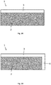
Fig. 3A is a graphical representation of the top coating of a membrane (1), which is provided with a finishing layer (2), except on a strip at a lateral edge (3) of the membrane. -
Fig. 3B is a graphical representation of the top coating of a membrane (1), which is provided with a finishing layer (2), except on a strip at a lateral edge (3) and transverse edge (4) of the membrane. -
Fig. 4 is a graphical representation of a transverse cross section of a membrane (1) comprising a top coating (5), a reinforcing layer (6), a metal layer (7) and a bottom coating (8), wherein the top coating (5) comprises a strip (9) which essentially has the same composition as the bottom coating (iv), which is different from the rest of the top coating. - As used throughout this text, the singular forms "a", "an", "the" include both the singular and the plural, unless the context clearly shows it to be different.
The terms "comprise", "comprises" as used throughout this text are synonymous with "including", "include" or "contain", "contains" and are inclusive or open, and do not exclude additional parts, elements or method steps which have not been mentioned. The terms "comprise", "comprises" include the term "contain".
The enumeration of numerical values by means of ranges of figures comprises all values and fractions in these ranges, as well as the terminal values mentioned.
The term "approximately", as used when reference is made to a measurable value, such as a parameter, an amount, a time duration, and so on, is intended to include variations of +/- 10% or less, preferably +/-5% or less, more preferably +/-1% or less, and still more preferably +/-0.1% or less, of and from the specified value, in so far as the variations are applicable to function in the disclosed invention. It should be understood that the value to which the term "approximately" refers has, per se, also been disclosed.
Any documents which are cited in the present specification are deemed to have been fully incorporated herein by reference.
Unless specified otherwise, all terms disclosed in the invention, including technical and scientific terms, have the meaning which a person skilled in the art usually attributes to them. As a further guideline, definitions are included to serve as further explanation of the terms which are used in the description of the invention. The invention comprises a method according toclaim 1 for fitting a roof covering in sections, wherein the roof covering comprises a membrane, wherein the membrane comprises bitumen and a metal, the method comprising the following steps: - (a) fitting the roof covering in sections, wherein one or more seams and/or overlapping regions are formed between the sections of roof covering;
- (b) heating the metal in the one or more seams and/or overlapping regions by means of magnetic induction; and
- (c) melting the bitumen in the one or more seams and/or overlapping regions together by heating the metal in step (b);
- the power provided to said one or more seams and/or overlapping regions via said induction coil; or
- the temperature of the seams and/or overlapping regions or overlapping membranes; or
- a combination thereof.
- The present method also has the advantage that relatively inaccessible parts (such as corners or edges) can be melted together by hand. As a result thereof, the roofer no longer requires an additional smaller welding apparatus (cf. hot-air and heat-welding). In order to be able to finish relatively inaccessible parts of the roof covering and, for example, also the details, the induction generator is provided with a removable part comprising the induction coil, by means of which the relatively inaccessible parts can be finished using a smaller part of the induction generator which can be manipulated by hand during fitting of the roof covering.
This will be explained in more detail below. - In this application, the term "bitumen" is understood to mean a visco-elastic liquid which forms a natural component of petroleum. After fractional distillation, bitumen can be separated from other constituents of the petroleum, such as naphtha, gasoline or diesel, and remains behind as the heaviest constituent. Bitumen mainly consists of hydrocarbons. It is also possible to use substances of vegetable origin which are similar to bitumen as alternatives. For use in roof covering, bitumen is usually used in a modified form. Modified bitumen consists of bitumen and one or more chemical agents, such as inter alia polymers and additives, such as resins and waxes. For roof covering, use is often made of bitumen modified with styrene butadiene styrene (SBS), bitumen modified with thermoplastic polyolefins (TPO) and/or bitumen modified with atactic polypropylene (APP).
The term "seams", as used herein, is understood to mean the gaps between two sections of roof covering. More specifically, the seam is understood to be the location where two sections of material are or will be attached to each other.
The term "overlapping regions", as used herein, is understood to mean the area in which two sections of roof covering or membranes overlap one another.
In particular embodiments, the speed of the generator is regulated based on a measurement of the power, i.e. (heat) energy per unit of time, provided to said one or more seams and/or overlapping regions via said induction coil. Typically, the power provided to the seams and/or overlapping regions via the induction coil will be measured by measuring the power consumed by the induction coil (power output). More particularly, the present inventors have found that in practice, the power provided to the seams and/or overlapping regions can be considered being approximately equal to or a certain fraction of the power consumed by the induction coil. - More particularly, the speed may be regulated based on the power provided to the seams, such that the energy density which is provided to the seams and/or overlapping regions is constant, or within a certain predetermined range. This is also referred to herein as "energy density monitoring". The term "energy density" as used herein refers to the (heat) energy provided per unit of length. As indicated above, the power is equal to the (heat) energy per unit of time. Accordingly, the speed required for providing a predetermined energy density to the seams and/or overlapping regions can be determined by measuring the power provided to the seams and/or overlapping regions, and dividing the measured power by the predetermined energy density. More particularly, the higher the power output of the induction coil the lower the speed will be, and vice versa.
Thus, the speed of the generator may be regulated (automatically) in order to provide the seams and/or overlapping regions with a predetermined energy density. The preferred energy density values can be determined empirically for each membrane type, and may depend of parameters such as membrane thickness, membrane composition, and membrane temperature. - In particular embodiments, the speed of the generator is regulated based on a measurement of the temperature of the seams and/or overlapping regions or overlapping membranes which are being heated using the induction generator. More specifically, the speed may be regulated (automatically) such that the temperature of the seams and/or overlapping regions is within a predetermined temperature range. Typically, a higher measured temperature will result in a lower speed. For example, the speed can be increased if the measured temperature is above a first value and decreased if the measured temperature is below a second value, wherein the first value is higher than or identical to the second value.
The preferred temperature can be determined empirically for each membrane type, and may depend of parameters such as membrane thickness and membrane composition. In particular embodiments, the speed is determined or regulated by a temperature measurement of the bitumen in step (c); and the speed is adjusted so that the temperature is at least 60°C and at most 160°C, preferably at least 61°C and at most 150°C, preferably at least 62°C and at most 140°C, preferably at least 63°C and at most 130°C, preferably at least 64°C and at most 120°C, preferably at least 65°C and at most 110°C, preferably at least 66°C and at most 105°C, preferably at least 67°C and at most 100°C, preferably at least 68°C and at most 95°C, preferably at least 69°C and at most 92°C, preferably at least 70°C and at most 90°C, and preferably approximately 70°C, 75°C, 80°C, 85°C or 90°C. - In particular embodiments, the speed of the generator is regulated based on a combination of temperature measurements and power measurements as described above. The present inventors have found that when moving the (induction coil of) the generator by hand, e.g. for details which are difficult to access, the best results were obtained when regulating the speed based on a temperature measurement. However, when using an automated motorized generator, e.g. for areas which are easily accessed, the best results were obtained based on a power measurement. Thus, in certain embodiments, the speed may be regulated based on a temperature measurement when the induction coil is moved manually; and based on a power measurement when the induction coil is moved automatically.
In a preferred embodiment, and regardless whether the speed is determined or regulated by a temperature measurement and/or a power measurement, the speed is at least 1 m/min and at most 15 m/min, preferably at least 2 m/min and at most 10 m/min, preferably at least 3 m/min and at most 7 m/min, and preferably 3 m/min, 3.5 m/min, 4 m/min, 4.5 m/min, 5 m/min, 5.5 m/min, 6 m/min, 6.5 m/min or 7 m/min.
In particular embodiments, temperature monitoring and/or energy density monitoring may be used to regulate both the speed and the power of the induction coil. This may allow for a smoother movement of the induction generator. - In a preferred embodiment, the method furthermore comprises the step:
- (d) pressing down the membrane in the one or more seams and/or overlapping regions.
- In a preferred embodiment, the one or more seams have a width of at most 5 mm, preferably at most 2.5 mm, preferably at most 1.0 mm, preferably at most 0.5 mm, preferably at most 0.2 mm, preferably at most 0.1 mm. In case seams are used, there is also the possibility to provide a membrane on top of the seam as a sealing strip which covers the seam. The sealing strip is preferably a membrane identical to the other membranes. Sealing is effected by treating the sealing strip via induction in the way as described herein. According to the invention, the membrane used in the method comprises the following layers:
- (i) a top coating, comprising bitumen and/or modified bitumen on top of
- (ii) a reinforcing layer on top of
- (iii) a complete or partial metal layer on top of
- (iv) a bottom coating, comprising bitumen and/or modified bitumen.
- The membrane may also comprise other layers, such as a finishing layer, a foil/film, a fleece, a web, etc. The membrane may, for example, comprise further finishing layers. The membrane may comprise a top finishing layer, in which use is made of materials such as sand, slate chippings, granules, stone chippings, anthracite, fleece, etc. The membrane may comprise a bottom finishing layer, in which use is made of materials such as sand, slate chippings, granules, stone chippings, anthracite, fleece, etc. The top finishing layer and the bottom finishing layer may be the same or different.
The present inventors have found that an improved adhesion between overlapping membranes can be obtained if the parts of the top coating (i) and bottom coating (iv) which are part of overlapping areas and are to be melted together, are free from finishing layers, in particular finishing layers comprising sand, slate chippings, granules, stone chippings, anthracite, fleece, etc.
Accordingly, in particular embodiments, the top coating (i) of the membranes may be provided with a top finishing layer, except for a lateral strip which is free from said finishing layer. The strip preferably has a width of at least 5 cm and at most 20 cm, preferably at least 7 cm and at most 14 cm. Most preferably, such strip has a width of approximately 10 cm. The lateral strip is typically provided in the longitudinal direction of the membrane as shown inFig. 3A , but may continue in the transverse direction, as shown inFig. 3B .
In certain embodiments, the bottom coating (iv) of the membranes may be provided with a bottom finishing layer, except for a lateral strip which is free from said finishing layer. The strip preferably has a width of at least 5 cm and at most 20 cm, preferably at least 7 cm and at most 14 cm. Most preferably, such strip has a width of approximately 10 cm. Again, the lateral strip may be provided in the longitudinal direction only, or continue in the transverse direction.
If the membranes are provided with a top finishing layer and a bottom finishing layer, except for a strip as described above, it is preferred that the strip of the top coating and the strip of the bottom layer are provided on laterally opposed sides of the membrane. The strips may be obtained by covering the membrane with a protective foil strip when applying the finishing layer.
In particular embodiments, the bottom layer may be provided with an adhesive, more particularly to make the membrane self-adhesive. Self-adhesive membranes are currently primarily used as bottom layers, as their seams are typically not sufficiently watertight. As the present membranes further comprise a metal layer (iii) which allows for inductive heating, the watertightness of the seams can be significantly improved, such that the self-adhesive layers can also be used as top layers.
In a preferred embodiment, the top coating (i) comprises modified bitumen. Preferably, the top coating (i) has a thickness of 0.1 to 5.0 mm. In a preferred embodiment, the bottom coating (iv) comprises modified bitumen. Preferably, the bottom coating (iv) has a thickness of 0.1 to 5.0 mm. The thickness of the top coating (i) may be the same or different from the thickness of the bottom coating (iv).
The modified bitumen is preferably a mixture of bitumen and plastics, polymers and/or thermoplastic polymers. In a preferred embodiment, plastics such as chlorosulfonyl polyethylene (CSM), ethylene ethyl acrylate (EEA), ethylene butyl acrylate (EBA), ethylene copolymer bitumen (ECB or EBT), ethylene vinyl acetate (EVAC), flexible polyolefin (FPO or PO-F), flexible polypropylene (FPP or PP-F), polyethylene (PE), chlorinated polyethylene (PE-C), polyisobutylene (PIB), polypropylene (PP) and/or polyvinyl chloride (PVC) are used. In a preferred embodiment, polymers such as butadiene, chloroprene, chlorosulfonyl polyethylene, terpolymer of ethylene or propylene, isobutene isoprene and/or acrylonitrile butadiene are used. In a preferred embodiment, thermoplastic polymers, such as elastomers, styrene ethylene butylene styrene, crosslinked and non-crosslinked thermoplastic elastomers, styrene butadiene styrene (SBS), styrene isoprene styrene (SIS), thermoplastic polyolefins (TPO) and/or atactic polypropylene (APP) are used. Preferably, bitumen modified with styrene butadiene styrene (SBS), bitumen modified with atactic polypropylene (APP) and/or bitumen modified with thermoplastic polyolefins (TPO) is used. According to the invention the top coating (i) and bottom coating (iv) have different compositions. Excellent results can be obtained using materials having a different hardness, more specifically when the top layer is harder than the bottom layer. Preferably, the top coating (i) contains bitumen modified with atactic polypropylene (APP) and/or bitumen modified with thermoplastic polyolefins (TPO) and the bottom coating (iv) contains bitumen modified with styrene butadiene styrene (SBS).
In particular embodiments, the top coating (i) may not have a uniform composition. More particularly, the composition of the top coating (i) may vary along the width of the membrane. For example, the top coating (i) may have regions which have essentially the same composition as the bottom coating (iv), and regions which have a different composition than the bottom coating (iv). Preferably, the region having essentially the same composition as the bottom coating (iv) is a strip (9) along a lateral edge of the membrane (1), as shown inFig. 4 . In a preferred embodiment, the strip has a width of at least 5 cm and at most 20 cm, preferably at least 7 cm and at most 14 cm, more preferably approximately 10 cm. This ensures that the overlapping regions of the membranes have uniform properties, while still allowing using different compositions for the top coating (i) and bottom coating (iv).
The skilled person will understand that the same may apply to the bottom coating, mutatis mutandis. Thus, additionally or alternatively, the composition of the bottom coating (iv) may vary along the width of the membrane. - In a preferred embodiment, the reinforcing layer (ii) comprises polyester, glass, polyester/glass, etc. The reinforcing layer ensures that the membrane provides sufficient support and mechanical properties to the membrane. Polyester and polyester/glass composite materials are particularly preferred. The inventors have found that such reinforcing layers result in membranes which are less prone to stretch forces.
In a preferred embodiment, the reinforcing layer (ii) comprises scrim, gauze, fleece, etc, preferably a scrim or gauze such as glass scrim, polyester scrim, polyester/glass scrim, etc. The use of glass scrim, polyester scrim and/or polyester/glass scrim in the reinforcing layer; and particularly polyester scrim and/or polyester/glass composite scrim, provides the membrane with ideal strength.
The membrane comprises metal. Preferably, the membrane comprises aluminum, copper, iron, or an alloy such as steel (preferably stainless steel), more preferably the membrane comprises aluminum. In an embodiment, the metal layer (iii) comprises aluminum, copper, iron, or an alloy such as steel, for example stainless steel. In a preferred embodiment, the metal layer (iii) comprises aluminum.
In a preferred embodiment, the metal layer (iii) has a thickness of at least 10 µm and at most 500 µm, preferably of at least 30 µm and at most 300 µm, preferably of at least 40 µm and at most 200 µm.
In a preferred embodiment, the metal layer (iii) is present at a weight per unit area of at least 10 g/m2 and at most 500 g/m2, preferably of at least 40 g/m2 and at most 300 g/m2, preferably of at least 60 g/m2 and at most 200 g/m2, preferably of at least 80 g/m2 and at most 200 g/m2, preferably of at least 100 g/m2 and at most 150 g/m2.
In a particular embodiment, the metal layer (iii) is a partial layer or edge layer which is present at the (lateral and/or transversal) edges of the roof covering, preferably the metal layer is arranged at a distance of at most 20 cm from at least one of the edges of the membrane, preferably at a distance of at most 10 cm, preferably at a distance of at most 5 cm, preferably at a distance from the edge of at most 1 cm, preferably on at least one of the edges of the membrane. The provision of the metal layer (iii) as a partial layer or edge layer allows for reducing the material cost for producing the membranes.
In a particular embodiment, the metal layer (iii) is a partial layer selected from the group comprising: one or more strips, a lattice, or one or more threads. - In a particular embodiment, the metal layer (iii) is a strip having a width of at least 0.1 cm and at most 110 cm, preferably at least 2 cm and at most 15 cm, preferably at least 4 cm and at most 6 cm, preferably approximately 5 cm. Such a width may ensure optimum heat control. If the strip is too narrow, the bitumen does not heat up to a sufficient degree, while a strip which is too wide may lead to burning through.
Whereas the provision of only a lateral edge with a metal layer is quite simple, the provision of a lateral edge and a transversal edge of the membrane is more complex. Therefore, in certain embodiments, the metal layer (iii) may be provided along essentially the entire width and length of the membrane. Such metal layer (iii) may be partial layer, e.g. a metal foil provided with perforations. The perforations may result in various foil geometries, and may include lattice structures.
In a preferred embodiment, the metal layer (iii) comprises a lattice. The use of a metal layer in the form of a lattice ensures uniform heat distribution across the membrane. In particular embodiments, the lattice may be a rectangular or square lattice.
In a preferred embodiment, the metal layer (iii) comprises one or more threads, preferably with the one or more threads running parallel to one another or the one or more threads running perpendicular to one another.
In a preferred embodiment, the membrane has a total thickness of at least 0.5 mm and at most 10.5 mm, preferably of at least 0.5 mm and at most 5 mm; for example about 3 mm. The invention discloses an induction generator suitable for the method according to the first aspect. In preferred embodiments, the generator comprises means for determining the power provided to the one or more seams and/or overlapping regions. More particularly, the generator may comprise means for determining the power output or power consumed by the induction coil. In preferred embodiments, the induction generator comprises a means for temperature monitoring. Typically, the generator will also comprise a computer chip which is provided with software for regulating the speed of the generator based on the measured power and/or temperature. - Preferably, the induction generator is limited in weight and size. Preferably, the induction generator weighs at most 30 kg, more preferably at most 25 kg, more preferably at most 20 kg. Preferably, the induction generator is provided with associated air cooling means. Preferably, the induction generator is self-propelled. Preferably, the induction generator is safe and ergonomic.
In a preferred embodiment, the means for temperature monitoring comprises an infrared (IR) sensor, more preferably an IR sensor with laser aligner. An IR sensor allows for determining the temperature of the membrane surface, which is indicative of the internal temperature at the seam or overlapping region.
In a preferred embodiment, the induction generator comprises a location-determining means.
In a preferred embodiment, the location-determining means comprises a GPS, preferably a real-time kinematic GPS.
The induction generator described herein is provided with one or more induction coils. In a particular embodiment, the induction generator comprises two induction coils in line with one another, wherein the induction coils are configured to heat up the metal. In other embodiments, the induction generator comprises a single induction coil.
Preferably, the induction generator comprises a removable part comprising an induction coil. More particularly, the induction generator may be provided on a removable part which is connected to the rest of the induction generator via one or more cables, thereby allowing movement of said removable part with respect to the rest of the induction generator. Preferably, the removable part also comprises the location-determining means. The removable part may be used for sealing the cross seams (end seams) and seams on non-horizontal surfaces. The removable part is preferably connected to a central part of the induction generator via a power and/or data cable. This central part preferably comprises a motor, an induction coil (preferably with a fan for air cooling) and/or a processor. The central part preferably comprises an induction coil which is situated closer to the edge of the membrane and causes hot bitumen to flow out. This acts as a visual check for the watertightness. In an embodiment, the induction generator is manipulated by a roofer by means of an extending and/or adjustable arm, which is optionally provided with an operating display. The electrical power may be provided via the arm. - In a preferred embodiment, the induction generator comprises a pressure-exerting roller. In an embodiment, the induction generator comprises at least two wheels, with one wheel preferably serving as a pressure-exerting roller. Preferably, this is the largest wheel. In certain embodiments, the induction generator comprises at least three wheels, with one wheel preferably serving as a pressure-exerting roller.
Preferably, the induction generator will be provided with an interface which allows for the user to select a predetermined temperature or temperature range which is to be achieved. Preferably, the induction generator will be provided with an interface which allows for the user to select a predetermined energy density or energy density range which is to be achieved. Such interface may comprise elements such as knobs, dials, a screen, a touchscreen, and the like.In an embodiment, the induction generator comprises a U-shaped inductor or a pot-shaped inductor. In a preferred embodiment, the induction generator comprises a U-shaped inductor. This embodiment makes it possible to transfer more energy to the metal.
In a preferred embodiment, the induction generator has a frequency of at least 10 kHz and at most 400 kHz.
The generator will typically move in a direction such that the seams and/or overlapping regions of the membranes are first heated, and then pressed with a pressure-exerting roller. In particular embodiments, the induction coil and pressure-exerting roller may be provided such that their relative position is interchangeable. This allows for moving the generator in two directions, while obtaining optimal results in each direction. This can significantly facilitate the use of the generator.
In particular embodiments, the induction generator may be provided with a handle which can be moved between two positions, more particularly to the front and to the back of the generator. This allows for the user to choose whether to walk behind or in front of the generator, thereby facilitating the use thereof. -
Duo Tack 3 AGR/F C250 was used as membrane. This membrane has a top coating of TPO plastomer bitumen, a reinforcing layer of polyester and glass scrim and a bottom coating of SBS elastomer self-adhesive bitumen. A glass scrim with the aluminum facing downwards was used as reinforcing layer. - First, the test sections were prepared. After the backing film had been removed, the test sections were placed on top of each other and pressed down using a foot. The test sections, except the reference sections, were made watertight by means of induction, with the speed being varied.
- 1 meter per 60 sec resulted in a temperature in the bitumen of approximately ± 60 °C.
- 1 meter per 90 sec resulted in a temperature in the bitumen of approximately ± 70 °C.
- 1 meter per 120 sec resulted in a temperature in the bitumen of approximately ± 80 °C.
- After sticking them together, the test sections are additionally pressed down again by running a pressure-exerting roller over them once. In order to stick the cross seams together, the machine was passed across the
test piece 3 times in succession, after which they were additionally pressed down by running the pressure-exerting roller over them once. The overlap was 10 cm wide. - The test sections were cut into the correct test shape according to European standard CSN EN 12316-1 and CSN EN 12317-1 3 days after being stuck together. One week later, after conditioning in the laboratory, the peel strength and shear strength tests were carried out (initial) and the samples for ageing (28 days at 80°C) were inserted.
- The following tests were carried out:
- 1. Peel strength tests 180° longitudinal seam (initial and after ageing)
- 2. Shear strength tests cross seam: 10 cm overlap (initial and after ageing)
- 3. Shear strength tests longitudinal seam: 8.5 cm overlap (initial and after ageing)
- The tests were carried out on the following samples:
- A) Ref. sample (only pressed down with pressure-exerting roller)
- B) Sample induction 60°C
- C) Sample induction 70°C
- D) Sample induction 80°C
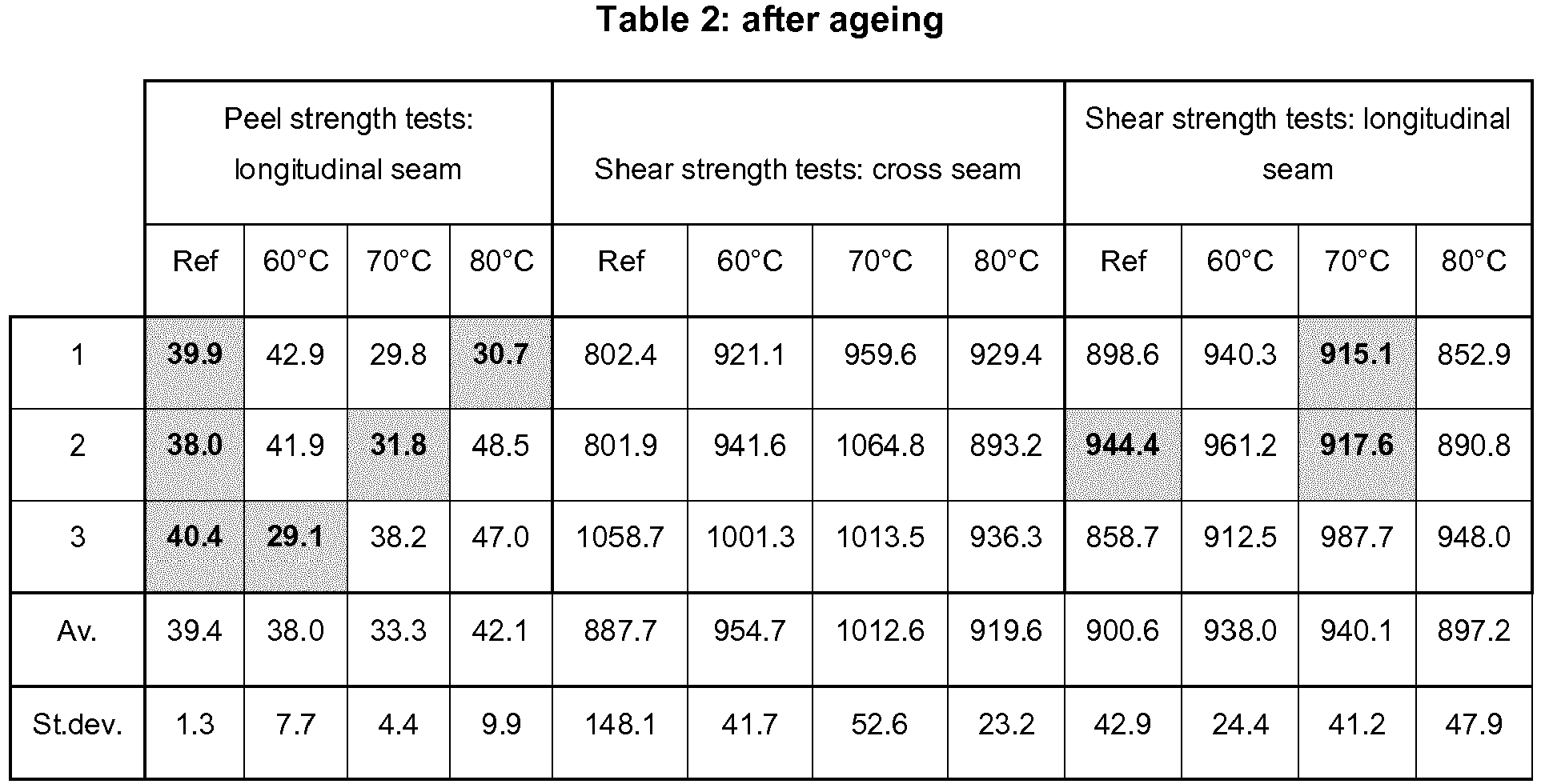
- Tables 1 and 2 show the results of these tests, with the results in bold type indicating that the seam became detached.

- It can be concluded from the initial tests that induction improves adhesive power. The peel strength tests show that the seam becomes detached more easily with the reference samples than with the induction samples. Not much can be concluded from the shear strength tests for the longitudinal seam, as there is always a fracture above or below the seam join, so the seam join is stronger. With the shear strength tests for the cross seam, a difference can be seen between the reference samples and the samples with induction. With the reference samples, the seams always detach, but with the samples with induction, the seams do not detach (always fracture above or below the seam join, so the seam join is stronger). Microscopic research shows that the samples melted together by induction resulted in improved and more uniform bonding compared to the reference sample (presence of air bubbles which may lead to infiltration of water).
Picture 1 shows an image of the seam join of the reference sample. Air bubbles are present, there is no complete bonding.Picture 2 shows an image of the seam join melted together at 80°C. No air bubbles are present and there is therefore complete bonding. A slight deformation (well) in the TPO layer is even filled by the self-adhesive mixture. - After ageing, it can also be concluded that induction improves adhesive power. The peel strength tests show that the value of the peel strength test drops with the reference samples after ageing. The values of the samples with induction are similar to the initial values. The value of the peel strength test increases for the shear strength tests on the longitudinal and cross seams.
This method inter alia has the advantage that it is contactless: using an induction coil, the seam can be heated without the edge situated above it has to be lifted or even touched.
This method also has the advantage that a more simple and lightweight apparatus can be used. An induction coil and a pressure-exerting wheel can be positioned one behind the other. This is impossible with hot-air welding, as the supply of hot air has to take place laterally out of necessity. As a result thereof, apparatus for hot-air welding are automatically asymmetrical machines (it is impossible for the air supply and the pressure-exerting wheel to be aligned), comprising parts which have to be displaceable and foldable. Such apparatus also typically weigh 40 kg or more. The power supply can also be made lighter, such as for example 220 V instead of 400 V.
The present method also has the advantage that welding is effected without a flame and without hot air, as a result of which the safety of use for roofers and buildings is increased.
The method described herein can also be used for fitting roof covering around details. Usually, a roof comprises various constructions, such as chimneys or skylights, around which the roof covering is fitted. These constructions, which result in various overlapping sections of roof covering during fitting of the roof covering, are here regarded as details. According to the invention, the speed of the generator is regulated based on a measurement of:
In a preferred embodiment, the one or more overlapping regions have a width of at least 1 cm and at most 110 cm, preferably at least 5 cm and at most 20 cm, preferably at least 7 cm and at most 14 cm, preferably the one or more overlapping regions have a width of approximately 10 cm.
In another embodiment, the entire segment of roof covering is treated by means of induction.
Claims (15)
- A method for fitting a roof covering in sections, wherein the roof covering comprises a membrane (1),
wherein the membrane comprises bitumen and a metal, the method comprising the following steps:(a) fitting the roof covering in sections, wherein one or more seams and/or overlapping regions are formed between the sections of roof covering;(b) heating the metal in the one or more seams and/or overlapping regions by means of magnetic induction; and(c) melting the bitumen in the one or more seams and/or overlapping regions together by heating the metal in step (b);wherein step (b) is carried out by moving a generator comprising an induction coil over the one or more seams and/or overlapping regions at a certain speed, and wherein the speed is regulated based on a measurement of:- the power provided to said one or more seams and/or overlapping regions via said induction coil; or- the temperature of the seams and/or overlapping regions; or- a combination thereof;wherein the membrane comprises the following layers:(i) a top coating (5), comprising bitumen and/or modified bitumen on top of;(ii) a reinforcing layer (6) on top of;(iii) a complete or partial metal layer (7) on top of;(iv) a bottom coating (8), comprising bitumen and/or modified bitumen;wherein the top coating (5) and bottom coating (8) have different compositions. - The method as claimed in claim 1, wherein the speed is determined or regulated by a temperature measurement of the bitumen in step (c); and wherein the speed is adjusted so that the temperature is at least 60°C and at most 160°C.
- The method as claimed in claim 1 or 2, wherein the speed is at least 0.5 m/min and at most 15 m/min.
- The method as claimed in one of claims 1 to 3, furthermore comprising the step:(d) pressing down the membrane in the one or more seams and/or overlapping regions.
- The method as claimed in one of claims 1 to 4 wherein the reinforcing layer (6) comprises a scrim or a gauze.
- The method according to one of claim 5 wherein the reinforcing layer (6) comprises a glass scrim, a polyester scrim and/or a polyester/glass scrim.
- The method as claimed in one of claims 1 to 6, wherein the metal layer (7) is situated underneath the reinforcing layer (6) when the membrane is fitted to a roof.
- The method as claimed in one of claims 1 to 7, wherein the top coating (5) comprises modified bitumen, and/or wherein the bottom coating (iv) comprises modified bitumen.
- The method as claimed in one of claims 1 to 8 wherein the generator comprises means for temperature monitoring, the means for temperature monitoring preferably comprising an IR sensor with a laser aligner.
- The method as claimed in one of claims 1 to 9, wherein the metal layer (7) comprises aluminum.
- The method as claimed in one of claims 1 to 10, wherein the metal layer (7) is a partial layer or edge layer.
- The method as claimed in one of claims 1 to 11, wherein the metal layer (7) is a partial layer selected from the group comprising: one or more strips, a lattice, or one or more threads.
- The method as claimed in one of claims 1 to 12, wherein the metal layer (7) is a band having a width of at least 0.1 cm and at most 110 cm.
- The method as claimed in one of claims 1 to 13, wherein the generator comprises a location-determining means.
- The method as claimed in claim 14, wherein the location-determining means comprises a GPS, preferably a real-time kinematic GPS.
Applications Claiming Priority (2)
| Application Number | Priority Date | Filing Date | Title |
|---|---|---|---|
| BE2013/0815A BE1021183B1 (en) | 2013-12-05 | 2013-12-05 | METHOD FOR WATERPROOF SEALING OF ROOF COVER |
| PCT/EP2014/076709 WO2015082680A1 (en) | 2013-12-05 | 2014-12-05 | Method for waterproofing a roof covering |
Publications (2)
| Publication Number | Publication Date |
|---|---|
| EP3077604A1 EP3077604A1 (en) | 2016-10-12 |
| EP3077604B1 true EP3077604B1 (en) | 2019-02-20 |
Family
ID=50101644
Family Applications (1)
| Application Number | Title | Priority Date | Filing Date |
|---|---|---|---|
| EP14816146.6A Not-in-force EP3077604B1 (en) | 2013-12-05 | 2014-12-05 | Method for waterproofing a roof covering |
Country Status (6)
| Country | Link |
|---|---|
| EP (1) | EP3077604B1 (en) |
| JP (1) | JP6553079B2 (en) |
| BE (1) | BE1021183B1 (en) |
| DK (1) | DK3077604T3 (en) |
| NZ (1) | NZ721412A (en) |
| WO (1) | WO2015082680A1 (en) |
Cited By (1)
| Publication number | Priority date | Publication date | Assignee | Title |
|---|---|---|---|---|
| WO2026046731A1 (en) * | 2024-08-26 | 2026-03-05 | Roslev Sustainable Holding Aps | Method of manufacturing a length of a composite sheet material |
Families Citing this family (4)
| Publication number | Priority date | Publication date | Assignee | Title |
|---|---|---|---|---|
| JP2018526656A (en) * | 2015-06-19 | 2018-09-13 | オーエムジー インコーポレイテッド | Mounting system and method for mapping building components |
| NL2023452B1 (en) * | 2019-07-08 | 2021-02-02 | Univ Delft Tech | Inductive Bituminous Waterproofing Membrane |
| EP4050176B1 (en) * | 2021-02-25 | 2025-09-24 | Wilfried Santo | Method for making a feedthrough through a roof lining |
| IL304785B2 (en) * | 2023-07-26 | 2024-06-01 | Bnp Innovation Ltd | Coating for surfaces and method of use |
Family Cites Families (7)
| Publication number | Priority date | Publication date | Assignee | Title |
|---|---|---|---|---|
| FR2622144B1 (en) * | 1987-10-27 | 1990-03-09 | Gerland Etancheite Sa | METHOD FOR WELDING SEALS, SEALS AND WELDING DEVICE FOR CARRYING OUT SAID METHOD |
| JPH03271450A (en) * | 1990-03-20 | 1991-12-03 | Kaname Yamamoto | Asphalt waterproofing method and material |
| SE501045C2 (en) * | 1990-09-17 | 1994-10-24 | Roofer Int Ab | Method of laying roofing board and device for carrying out the procedure |
| DE10008689A1 (en) * | 2000-02-24 | 2001-10-04 | Vedag Dachsysteme Gmbh & Co Kg | Process for laying bituminous waterproofing membranes and suitable waterproofing membranes and roof waterproofing made from them |
| US20050103437A1 (en) * | 2003-11-19 | 2005-05-19 | Carroll James M. | Seaming iron with automatic traction |
| JP5212764B2 (en) * | 2006-06-08 | 2013-06-19 | 日新工業株式会社 | Roof material and its construction method |
| ITVI20120068A1 (en) * | 2012-03-26 | 2013-09-27 | Gen Membrane S P A | CONNECTION DEVICE FOR SHEETS OF BITUMINOUS MEMBRANES AND BITUMINOUS MEMBRANE INCLUDING A CONNECTION DEVICE |
-
2013
- 2013-12-05 BE BE2013/0815A patent/BE1021183B1/en not_active IP Right Cessation
-
2014
- 2014-12-05 EP EP14816146.6A patent/EP3077604B1/en not_active Not-in-force
- 2014-12-05 JP JP2016557190A patent/JP6553079B2/en not_active Expired - Fee Related
- 2014-12-05 WO PCT/EP2014/076709 patent/WO2015082680A1/en not_active Ceased
- 2014-12-05 DK DK14816146.6T patent/DK3077604T3/en active
- 2014-12-05 NZ NZ721412A patent/NZ721412A/en unknown
Non-Patent Citations (1)
| Title |
|---|
| None * |
Cited By (1)
| Publication number | Priority date | Publication date | Assignee | Title |
|---|---|---|---|---|
| WO2026046731A1 (en) * | 2024-08-26 | 2026-03-05 | Roslev Sustainable Holding Aps | Method of manufacturing a length of a composite sheet material |
Also Published As
| Publication number | Publication date |
|---|---|
| WO2015082680A1 (en) | 2015-06-11 |
| BE1021183B1 (en) | 2015-06-09 |
| DK3077604T3 (en) | 2019-05-06 |
| EP3077604A1 (en) | 2016-10-12 |
| JP6553079B2 (en) | 2019-07-31 |
| JP2017503098A (en) | 2017-01-26 |
| NZ721412A (en) | 2020-11-27 |
Similar Documents
| Publication | Publication Date | Title |
|---|---|---|
| JP6553079B2 (en) | Methods for waterproofing roofing | |
| US20090017226A1 (en) | Use of infrared technology to install and/or repair construction membranes | |
| CN107128052B (en) | A kind of modified asphalt waterproof coiled material and preparation method thereof and construction technology | |
| US7803239B2 (en) | Self-adhered roofing components, roofing system, and method | |
| US2084625A (en) | Method and apparatus for laying sheet material | |
| CA2691835A1 (en) | Composite roofing or other surfacing board, method of making and using and roof made thereby | |
| US9863100B2 (en) | Methods for joining strips of synthetic turf by blade-to-loop tuft bonding and for covering a site with synthetic turf | |
| US6537402B2 (en) | Membrane welding apparatus including a visual seam marker | |
| CN103802309B (en) | Refuse landfill HDPE film welding method | |
| CN104411899B (en) | Apparatus for heating and joining sheets of asphalt or synthetic membranes and their asphalt or synthetic membranes | |
| Oba et al. | Study on seam performance of polymer-modified bituminous roofing membranes using T-peel test and microscopy | |
| US4654109A (en) | Hot trowel device and method | |
| JPH04368563A (en) | Flooring bonding method and flooring adhesive tape | |
| JP2003191336A (en) | How to join waterproof and impermeable sheets | |
| CN211710255U (en) | Waterproofing membrane with temperature indicator strip | |
| CN211518540U (en) | Pressure oil waterproof construction device for coiled material overlap edge compression roller | |
| Oba et al. | Welding methods with reduced fire hazard for single‐ply polymer‐modified bituminous roofing materials | |
| GB2516946A (en) | Application of Plastic to Substrates | |
| Karablikovas et al. | The research on gluing relia bility of glued roller cover membranes | |
| CN207528493U (en) | A kind of soft modeling pitch sampler of temperature automatically controlled solid | |
| JP2003293527A (en) | How to join waterproof and impermeable sheets | |
| JP2003293526A (en) | How to join waterproof and impermeable sheets | |
| CN108868138B (en) | Integrated bottom surface laying method for PVC waterproof coiled material | |
| Carson et al. | Techniques for the fabrication of geomembrane filled seams | |
| JP2004332271A (en) | Waterproof sheet corresponding to environment and its execution method |
Legal Events
| Date | Code | Title | Description |
|---|---|---|---|
| PUAI | Public reference made under article 153(3) epc to a published international application that has entered the european phase |
Free format text: ORIGINAL CODE: 0009012 |
|
| 17P | Request for examination filed |
Effective date: 20160623 |
|
| AK | Designated contracting states |
Kind code of ref document: A1 Designated state(s): AL AT BE BG CH CY CZ DE DK EE ES FI FR GB GR HR HU IE IS IT LI LT LU LV MC MK MT NL NO PL PT RO RS SE SI SK SM TR |
|
| AX | Request for extension of the european patent |
Extension state: BA ME |
|
| DAX | Request for extension of the european patent (deleted) | ||
| GRAP | Despatch of communication of intention to grant a patent |
Free format text: ORIGINAL CODE: EPIDOSNIGR1 |
|
| STAA | Information on the status of an ep patent application or granted ep patent |
Free format text: STATUS: GRANT OF PATENT IS INTENDED |
|
| INTG | Intention to grant announced |
Effective date: 20180321 |
|
| GRAJ | Information related to disapproval of communication of intention to grant by the applicant or resumption of examination proceedings by the epo deleted |
Free format text: ORIGINAL CODE: EPIDOSDIGR1 |
|
| STAA | Information on the status of an ep patent application or granted ep patent |
Free format text: STATUS: REQUEST FOR EXAMINATION WAS MADE |
|
| GRAP | Despatch of communication of intention to grant a patent |
Free format text: ORIGINAL CODE: EPIDOSNIGR1 |
|
| STAA | Information on the status of an ep patent application or granted ep patent |
Free format text: STATUS: GRANT OF PATENT IS INTENDED |
|
| INTC | Intention to grant announced (deleted) | ||
| INTG | Intention to grant announced |
Effective date: 20180815 |
|
| GRAS | Grant fee paid |
Free format text: ORIGINAL CODE: EPIDOSNIGR3 |
|
| GRAA | (expected) grant |
Free format text: ORIGINAL CODE: 0009210 |
|
| STAA | Information on the status of an ep patent application or granted ep patent |
Free format text: STATUS: THE PATENT HAS BEEN GRANTED |
|
| AK | Designated contracting states |
Kind code of ref document: B1 Designated state(s): AL AT BE BG CH CY CZ DE DK EE ES FI FR GB GR HR HU IE IS IT LI LT LU LV MC MK MT NL NO PL PT RO RS SE SI SK SM TR |
|
| REG | Reference to a national code |
Ref country code: GB Ref legal event code: FG4D |
|
| REG | Reference to a national code |
Ref country code: CH Ref legal event code: EP |
|
| REG | Reference to a national code |
Ref country code: DE Ref legal event code: R096 Ref document number: 602014041416 Country of ref document: DE |
|
| REG | Reference to a national code |
Ref country code: AT Ref legal event code: REF Ref document number: 1098361 Country of ref document: AT Kind code of ref document: T Effective date: 20190315 |
|
| REG | Reference to a national code |
Ref country code: IE Ref legal event code: FG4D |
|
| REG | Reference to a national code |
Ref country code: NO Ref legal event code: T2 Effective date: 20190220 |
|
| REG | Reference to a national code |
Ref country code: DK Ref legal event code: T3 Effective date: 20190429 |
|
| REG | Reference to a national code |
Ref country code: SE Ref legal event code: TRGR |
|
| REG | Reference to a national code |
Ref country code: NL Ref legal event code: FP |
|
| REG | Reference to a national code |
Ref country code: LT Ref legal event code: MG4D |
|
| PG25 | Lapsed in a contracting state [announced via postgrant information from national office to epo] |
Ref country code: PT Free format text: LAPSE BECAUSE OF FAILURE TO SUBMIT A TRANSLATION OF THE DESCRIPTION OR TO PAY THE FEE WITHIN THE PRESCRIBED TIME-LIMIT Effective date: 20190620 Ref country code: LT Free format text: LAPSE BECAUSE OF FAILURE TO SUBMIT A TRANSLATION OF THE DESCRIPTION OR TO PAY THE FEE WITHIN THE PRESCRIBED TIME-LIMIT Effective date: 20190220 Ref country code: FI Free format text: LAPSE BECAUSE OF FAILURE TO SUBMIT A TRANSLATION OF THE DESCRIPTION OR TO PAY THE FEE WITHIN THE PRESCRIBED TIME-LIMIT Effective date: 20190220 |
|
| PG25 | Lapsed in a contracting state [announced via postgrant information from national office to epo] |
Ref country code: GR Free format text: LAPSE BECAUSE OF FAILURE TO SUBMIT A TRANSLATION OF THE DESCRIPTION OR TO PAY THE FEE WITHIN THE PRESCRIBED TIME-LIMIT Effective date: 20190521 Ref country code: BG Free format text: LAPSE BECAUSE OF FAILURE TO SUBMIT A TRANSLATION OF THE DESCRIPTION OR TO PAY THE FEE WITHIN THE PRESCRIBED TIME-LIMIT Effective date: 20190520 Ref country code: IS Free format text: LAPSE BECAUSE OF FAILURE TO SUBMIT A TRANSLATION OF THE DESCRIPTION OR TO PAY THE FEE WITHIN THE PRESCRIBED TIME-LIMIT Effective date: 20190620 Ref country code: RS Free format text: LAPSE BECAUSE OF FAILURE TO SUBMIT A TRANSLATION OF THE DESCRIPTION OR TO PAY THE FEE WITHIN THE PRESCRIBED TIME-LIMIT Effective date: 20190220 Ref country code: HR Free format text: LAPSE BECAUSE OF FAILURE TO SUBMIT A TRANSLATION OF THE DESCRIPTION OR TO PAY THE FEE WITHIN THE PRESCRIBED TIME-LIMIT Effective date: 20190220 Ref country code: LV Free format text: LAPSE BECAUSE OF FAILURE TO SUBMIT A TRANSLATION OF THE DESCRIPTION OR TO PAY THE FEE WITHIN THE PRESCRIBED TIME-LIMIT Effective date: 20190220 |
|
| REG | Reference to a national code |
Ref country code: AT Ref legal event code: MK05 Ref document number: 1098361 Country of ref document: AT Kind code of ref document: T Effective date: 20190220 |
|
| PG25 | Lapsed in a contracting state [announced via postgrant information from national office to epo] |
Ref country code: IT Free format text: LAPSE BECAUSE OF FAILURE TO SUBMIT A TRANSLATION OF THE DESCRIPTION OR TO PAY THE FEE WITHIN THE PRESCRIBED TIME-LIMIT Effective date: 20190220 Ref country code: EE Free format text: LAPSE BECAUSE OF FAILURE TO SUBMIT A TRANSLATION OF THE DESCRIPTION OR TO PAY THE FEE WITHIN THE PRESCRIBED TIME-LIMIT Effective date: 20190220 Ref country code: CZ Free format text: LAPSE BECAUSE OF FAILURE TO SUBMIT A TRANSLATION OF THE DESCRIPTION OR TO PAY THE FEE WITHIN THE PRESCRIBED TIME-LIMIT Effective date: 20190220 Ref country code: SK Free format text: LAPSE BECAUSE OF FAILURE TO SUBMIT A TRANSLATION OF THE DESCRIPTION OR TO PAY THE FEE WITHIN THE PRESCRIBED TIME-LIMIT Effective date: 20190220 Ref country code: RO Free format text: LAPSE BECAUSE OF FAILURE TO SUBMIT A TRANSLATION OF THE DESCRIPTION OR TO PAY THE FEE WITHIN THE PRESCRIBED TIME-LIMIT Effective date: 20190220 Ref country code: AL Free format text: LAPSE BECAUSE OF FAILURE TO SUBMIT A TRANSLATION OF THE DESCRIPTION OR TO PAY THE FEE WITHIN THE PRESCRIBED TIME-LIMIT Effective date: 20190220 Ref country code: ES Free format text: LAPSE BECAUSE OF FAILURE TO SUBMIT A TRANSLATION OF THE DESCRIPTION OR TO PAY THE FEE WITHIN THE PRESCRIBED TIME-LIMIT Effective date: 20190220 |
|
| REG | Reference to a national code |
Ref country code: DE Ref legal event code: R097 Ref document number: 602014041416 Country of ref document: DE |
|
| PG25 | Lapsed in a contracting state [announced via postgrant information from national office to epo] |
Ref country code: SM Free format text: LAPSE BECAUSE OF FAILURE TO SUBMIT A TRANSLATION OF THE DESCRIPTION OR TO PAY THE FEE WITHIN THE PRESCRIBED TIME-LIMIT Effective date: 20190220 Ref country code: PL Free format text: LAPSE BECAUSE OF FAILURE TO SUBMIT A TRANSLATION OF THE DESCRIPTION OR TO PAY THE FEE WITHIN THE PRESCRIBED TIME-LIMIT Effective date: 20190220 |
|
| PLBE | No opposition filed within time limit |
Free format text: ORIGINAL CODE: 0009261 |
|
| STAA | Information on the status of an ep patent application or granted ep patent |
Free format text: STATUS: NO OPPOSITION FILED WITHIN TIME LIMIT |
|
| PG25 | Lapsed in a contracting state [announced via postgrant information from national office to epo] |
Ref country code: AT Free format text: LAPSE BECAUSE OF FAILURE TO SUBMIT A TRANSLATION OF THE DESCRIPTION OR TO PAY THE FEE WITHIN THE PRESCRIBED TIME-LIMIT Effective date: 20190220 |
|
| 26N | No opposition filed |
Effective date: 20191121 |
|
| PGFP | Annual fee paid to national office [announced via postgrant information from national office to epo] |
Ref country code: SE Payment date: 20191219 Year of fee payment: 6 Ref country code: NL Payment date: 20191219 Year of fee payment: 6 Ref country code: DE Payment date: 20191210 Year of fee payment: 6 Ref country code: IE Payment date: 20191220 Year of fee payment: 6 |
|
| PG25 | Lapsed in a contracting state [announced via postgrant information from national office to epo] |
Ref country code: SI Free format text: LAPSE BECAUSE OF FAILURE TO SUBMIT A TRANSLATION OF THE DESCRIPTION OR TO PAY THE FEE WITHIN THE PRESCRIBED TIME-LIMIT Effective date: 20190220 |
|
| PGFP | Annual fee paid to national office [announced via postgrant information from national office to epo] |
Ref country code: LU Payment date: 20191219 Year of fee payment: 6 Ref country code: FR Payment date: 20191220 Year of fee payment: 6 Ref country code: BE Payment date: 20191219 Year of fee payment: 6 Ref country code: DK Payment date: 20191227 Year of fee payment: 6 |
|
| REG | Reference to a national code |
Ref country code: DE Ref legal event code: R081 Ref document number: 602014041416 Country of ref document: DE Owner name: SOPREMA NV, BE Free format text: FORMER OWNER: DE BOER WATERPROOFING SOLUTIONS N.V., SCHOTEN, BE |
|
| REG | Reference to a national code |
Ref country code: NO Ref legal event code: CHAD Owner name: SOPREMA NV, BE |
|
| REG | Reference to a national code |
Ref country code: NL Ref legal event code: PD Owner name: SOPREMA NV; BE Free format text: DETAILS ASSIGNMENT: CHANGE OF OWNER(S), ASSIGNMENT; FORMER OWNER NAME: DE BOER WATERPROOFING SOLUTIONS N.V. Effective date: 20200316 |
|
| PG25 | Lapsed in a contracting state [announced via postgrant information from national office to epo] |
Ref country code: TR Free format text: LAPSE BECAUSE OF FAILURE TO SUBMIT A TRANSLATION OF THE DESCRIPTION OR TO PAY THE FEE WITHIN THE PRESCRIBED TIME-LIMIT Effective date: 20190220 |
|
| REG | Reference to a national code |
Ref country code: LU Ref legal event code: PD Owner name: SOPREMA NV; BE Free format text: FORMER OWNER: DE BOER WATERPROOFING SOLUTIONS N.V. Effective date: 20200306 |
|
| REG | Reference to a national code |
Ref country code: GB Ref legal event code: 732E Free format text: REGISTERED BETWEEN 20200319 AND 20200325 |
|
| REG | Reference to a national code |
Ref country code: BE Ref legal event code: HC Owner name: SOPREMA NV; BE Free format text: DETAILS ASSIGNMENT: CHANGE OF OWNER(S), CHANGEMENT DE NOM DU PROPRIETAIRE Effective date: 20200227 |
|
| PGFP | Annual fee paid to national office [announced via postgrant information from national office to epo] |
Ref country code: GB Payment date: 20191220 Year of fee payment: 6 Ref country code: NO Payment date: 20191223 Year of fee payment: 6 |
|
| REG | Reference to a national code |
Ref country code: CH Ref legal event code: PL |
|
| PG25 | Lapsed in a contracting state [announced via postgrant information from national office to epo] |
Ref country code: MC Free format text: LAPSE BECAUSE OF FAILURE TO SUBMIT A TRANSLATION OF THE DESCRIPTION OR TO PAY THE FEE WITHIN THE PRESCRIBED TIME-LIMIT Effective date: 20190220 |
|
| PG25 | Lapsed in a contracting state [announced via postgrant information from national office to epo] |
Ref country code: CH Free format text: LAPSE BECAUSE OF NON-PAYMENT OF DUE FEES Effective date: 20191231 Ref country code: LI Free format text: LAPSE BECAUSE OF NON-PAYMENT OF DUE FEES Effective date: 20191231 |
|
| PG25 | Lapsed in a contracting state [announced via postgrant information from national office to epo] |
Ref country code: CY Free format text: LAPSE BECAUSE OF FAILURE TO SUBMIT A TRANSLATION OF THE DESCRIPTION OR TO PAY THE FEE WITHIN THE PRESCRIBED TIME-LIMIT Effective date: 20190220 |
|
| REG | Reference to a national code |
Ref country code: DE Ref legal event code: R119 Ref document number: 602014041416 Country of ref document: DE |
|
| REG | Reference to a national code |
Ref country code: DK Ref legal event code: EBP Effective date: 20201231 |
|
| REG | Reference to a national code |
Ref country code: NO Ref legal event code: MMEP |
|
| PG25 | Lapsed in a contracting state [announced via postgrant information from national office to epo] |
Ref country code: HU Free format text: LAPSE BECAUSE OF FAILURE TO SUBMIT A TRANSLATION OF THE DESCRIPTION OR TO PAY THE FEE WITHIN THE PRESCRIBED TIME-LIMIT; INVALID AB INITIO Effective date: 20141205 Ref country code: MT Free format text: LAPSE BECAUSE OF FAILURE TO SUBMIT A TRANSLATION OF THE DESCRIPTION OR TO PAY THE FEE WITHIN THE PRESCRIBED TIME-LIMIT Effective date: 20190220 |
|
| REG | Reference to a national code |
Ref country code: SE Ref legal event code: EUG |
|
| REG | Reference to a national code |
Ref country code: NL Ref legal event code: MM Effective date: 20210101 |
|
| GBPC | Gb: european patent ceased through non-payment of renewal fee |
Effective date: 20201205 |
|
| REG | Reference to a national code |
Ref country code: BE Ref legal event code: MM Effective date: 20201231 |
|
| PG25 | Lapsed in a contracting state [announced via postgrant information from national office to epo] |
Ref country code: NL Free format text: LAPSE BECAUSE OF NON-PAYMENT OF DUE FEES Effective date: 20210101 |
|
| PG25 | Lapsed in a contracting state [announced via postgrant information from national office to epo] |
Ref country code: FR Free format text: LAPSE BECAUSE OF NON-PAYMENT OF DUE FEES Effective date: 20201231 Ref country code: LU Free format text: LAPSE BECAUSE OF NON-PAYMENT OF DUE FEES Effective date: 20201205 Ref country code: IE Free format text: LAPSE BECAUSE OF NON-PAYMENT OF DUE FEES Effective date: 20201205 |
|
| PG25 | Lapsed in a contracting state [announced via postgrant information from national office to epo] |
Ref country code: SE Free format text: LAPSE BECAUSE OF NON-PAYMENT OF DUE FEES Effective date: 20201206 Ref country code: NO Free format text: LAPSE BECAUSE OF NON-PAYMENT OF DUE FEES Effective date: 20201231 Ref country code: DE Free format text: LAPSE BECAUSE OF NON-PAYMENT OF DUE FEES Effective date: 20210701 Ref country code: GB Free format text: LAPSE BECAUSE OF NON-PAYMENT OF DUE FEES Effective date: 20201205 |
|
| PG25 | Lapsed in a contracting state [announced via postgrant information from national office to epo] |
Ref country code: DK Free format text: LAPSE BECAUSE OF NON-PAYMENT OF DUE FEES Effective date: 20201231 |
|
| PG25 | Lapsed in a contracting state [announced via postgrant information from national office to epo] |
Ref country code: MK Free format text: LAPSE BECAUSE OF FAILURE TO SUBMIT A TRANSLATION OF THE DESCRIPTION OR TO PAY THE FEE WITHIN THE PRESCRIBED TIME-LIMIT Effective date: 20190220 |
|
| PG25 | Lapsed in a contracting state [announced via postgrant information from national office to epo] |
Ref country code: BE Free format text: LAPSE BECAUSE OF NON-PAYMENT OF DUE FEES Effective date: 20201231 |