EP3077157B1 - Device for sharpening blades - Google Patents
Device for sharpening blades Download PDFInfo
- Publication number
- EP3077157B1 EP3077157B1 EP14809531.8A EP14809531A EP3077157B1 EP 3077157 B1 EP3077157 B1 EP 3077157B1 EP 14809531 A EP14809531 A EP 14809531A EP 3077157 B1 EP3077157 B1 EP 3077157B1
- Authority
- EP
- European Patent Office
- Prior art keywords
- blade
- grinding wheels
- movable supports
- sharpening device
- sharpening
- Prior art date
- Legal status (The legal status is an assumption and is not a legal conclusion. Google has not performed a legal analysis and makes no representation as to the accuracy of the status listed.)
- Active
Links
Images


Classifications
-
- B—PERFORMING OPERATIONS; TRANSPORTING
- B24—GRINDING; POLISHING
- B24B—MACHINES, DEVICES, OR PROCESSES FOR GRINDING OR POLISHING; DRESSING OR CONDITIONING OF ABRADING SURFACES; FEEDING OF GRINDING, POLISHING, OR LAPPING AGENTS
- B24B3/00—Sharpening cutting edges, e.g. of tools; Accessories therefor, e.g. for holding the tools
- B24B3/36—Sharpening cutting edges, e.g. of tools; Accessories therefor, e.g. for holding the tools of cutting blades
-
- B—PERFORMING OPERATIONS; TRANSPORTING
- B24—GRINDING; POLISHING
- B24B—MACHINES, DEVICES, OR PROCESSES FOR GRINDING OR POLISHING; DRESSING OR CONDITIONING OF ABRADING SURFACES; FEEDING OF GRINDING, POLISHING, OR LAPPING AGENTS
- B24B3/00—Sharpening cutting edges, e.g. of tools; Accessories therefor, e.g. for holding the tools
- B24B3/36—Sharpening cutting edges, e.g. of tools; Accessories therefor, e.g. for holding the tools of cutting blades
- B24B3/46—Sharpening cutting edges, e.g. of tools; Accessories therefor, e.g. for holding the tools of cutting blades of disc blades
-
- B—PERFORMING OPERATIONS; TRANSPORTING
- B24—GRINDING; POLISHING
- B24D—TOOLS FOR GRINDING, BUFFING OR SHARPENING
- B24D15/00—Hand tools or other devices for non-rotary grinding, polishing, or stropping
- B24D15/06—Hand tools or other devices for non-rotary grinding, polishing, or stropping specially designed for sharpening cutting edges
- B24D15/08—Hand tools or other devices for non-rotary grinding, polishing, or stropping specially designed for sharpening cutting edges of knives; of razors
-
- B—PERFORMING OPERATIONS; TRANSPORTING
- B24—GRINDING; POLISHING
- B24D—TOOLS FOR GRINDING, BUFFING OR SHARPENING
- B24D15/00—Hand tools or other devices for non-rotary grinding, polishing, or stropping
- B24D15/06—Hand tools or other devices for non-rotary grinding, polishing, or stropping specially designed for sharpening cutting edges
- B24D15/08—Hand tools or other devices for non-rotary grinding, polishing, or stropping specially designed for sharpening cutting edges of knives; of razors
- B24D15/081—Hand tools or other devices for non-rotary grinding, polishing, or stropping specially designed for sharpening cutting edges of knives; of razors with sharpening elements in interengaging or in mutual contact
- B24D15/082—Hand tools or other devices for non-rotary grinding, polishing, or stropping specially designed for sharpening cutting edges of knives; of razors with sharpening elements in interengaging or in mutual contact the elements being rotatable
-
- B—PERFORMING OPERATIONS; TRANSPORTING
- B26—HAND CUTTING TOOLS; CUTTING; SEVERING
- B26D—CUTTING; DETAILS COMMON TO MACHINES FOR PERFORATING, PUNCHING, CUTTING-OUT, STAMPING-OUT OR SEVERING
- B26D7/00—Details of apparatus for cutting, cutting-out, stamping-out, punching, perforating, or severing by means other than cutting
- B26D7/08—Means for treating work or cutting member to facilitate cutting
- B26D7/12—Means for treating work or cutting member to facilitate cutting by sharpening the cutting member
Definitions
- the present invention relates to a device for sharpening blades that can be used, in particular, for the production of paper rolls.
- a rewinder is used for winding a paper web around a cardboard core to obtain an intermediated product, commonly called "log", that is made by a paper roll wound around the core and is destined to be transversely cut to obtain rolls having a commercial size, i.e. shorter paper rolls.
- the transverse cut of the logs is made by means of cutting machines provided with circular blades or band saws.
- US2012/184186 discloses system for sharpening circular, knife edged blades that operates to bias an infeed grinding wheel into contact with the first edge of the blade and an outfeed grinding wheel into contact with the second edge of the blade.
- the grinding wheels are spaced so that they contact the respective edges of the blade at a point which is spaced by no more than 1 inch from the center line of the blade. Contact between the grinding wheels and the blade is accomplished solely by pushing the wheels from their sides which are opposite the blade contacting surface.
- the system includes provisions for adjusting the position of the wheels relative to the blade so as to accommodate blade wear.
- the transverse cut of the logs is particularly critical.
- the cutting of the logs along planes that are not perfectly orthogonal to the axis of the same involves the formation of defective rolls, in which the side bases are oblique.
- This drawback is even more serious when the rolls are intended to be used in automatic dispensers which require, in fact, rolls with the side bases perfectly orthogonal to the axis of the rolls themselves, otherwise the rolls tend to get jammed in the dispenser.
- the main object of the present invention is to allow an effective sharpening of blades with a device that can equip permanently the cutting machine. This result is achieved, according to the present invention, by adopting the idea of realizing a device having the features indicated in claim 1 Other features of the invention are the subject of the dependent claims.
- the present invention there is that it is possible to sharpen a blade effectively and quickly; that the sharpening can be performed by acting in real time, without interrupting the operation of the cutting machine; that the device can be activated in an automatic way, by connecting it to a respective control apparatus; that the present device can equip existing machines, and can be installed with relatively simple operations; that the present device does not require prolonged maintenance interventions, basically keeping its characteristics unchanged even if used for a long time.
- FIG. 1A schematically show a device in accordance with the present invention associated with a blade in a waiting configuration, represented, respectively, in a side view ( Fig.1A ) and a front view ( Fig.1B ), with parts removed and/or sectioned to better illustrate other parts;
- a device (1) in accordance with the present invention can be used for sharpening blades, in particular for a cutting machine provided with a blade (4).
- the blade (4) is provided with two inclined parts (bevels) that, joining with each other, form the sharp edge or cutting edge (40).
- the device (1) comprises two grinding wheels (2, 3) supported by corresponding movable arms (20, 30) which, on command, move said grinding wheels (2, 3) in contact with said sharp edge (40) to perform a sharpening operation.
- Said arms (20, 30) are fulcrated to each other so as to define a first-class double lever like scissors, with resistant force consisting in the friction generated by the contact of the grinding wheels (2, 3) with the blade (4).
- the fulcrum of the double lever formed by the arms (20, 30) has an axis (x) perpendicular to the cutting plane (P) defined by the sharp edge (40) of the blade (4).
- Said axis (x) is external to the blade and is parallel to a rotation axis (y) of the latter.
- the distal portions (L20, L30) of the arms (20, 30) have a length whose value is such that the grinding wheels (2, 3) can be moved along corresponding trajectories interfering with the sharp edge (40) of the blade (4) so as to allow sharpening as further described in the following.
- the block (M) in the drawings represents motor means acting on the proximal portions (200, 300) of said arms (20, 30) so as to constitute the force applied to the double lever formed by the same arms.
- the motor means (M) act bi-directionally so as to move the proximal portions (200, 300) of the arms (20, 30) towards or away from each other, thereby moving the distal portions of the arms that support the wheels (2, 3).
- the device can have at least two configurations: a standby or rest configuration, shown in Figg.1A and 1B, and an active configuration, shown in Figures 2a and 2B .
- the motor means (M) are not activated and maintain the proximal portions (200, 300) of the arms (20, 30) spaced from each other.
- the motor means (M) move the proximal portions (200, 300) of the arms (20, 30) towards each other, determining the corresponding approaching of the distal portions (201, 301) that support the grinding wheels (2, 3).
- each of the grinding wheels (2, 3) follows a trajectory having the shape of circular arc (indicated with R2 and R3 in Fig.1B ) which carries the same grinding wheels in contact with the blade (4) to perform sharpening.
- This trajectory allows a continuous and gradual approach of the grinding wheels to the respective sides of the blade (4).
- the contact of each grinding wheel (2, 3) with the respective side of the cutting edge of the blade (4) is progressive, whereby the contact area between the grinding wheels and the blade increases progressively when the device passes from the rest configuration to the active configuration. Hence, a better blade sharpening is achieved and the structural integrity of the blade is preserved.
- the axis of said circular arcs (R2, R3) coincides with the afore-mentioned axis (x) and each arc (R2, R3) is parallel to said cutting plane (P). Therefore, when moved by the arms (20, 30), the grinding wheels (2, 3) run along respective arcuate trajectories (R2, R3) parallel to the sides (41) of the blade (4).
- Said arms (20, 30) can be advantageously connected with suitable pressure sensors adapted to detect the pressure exerted by each wheel (2, 3) on the respective side of the blade (4).
- said pressure sensors can be connected to the motor means (M), by means of a corresponding control unit, to control the action of the same motor means (M) on the arms (20, 30), i.e. to control the pressure exerted by the grinding wheels (2, 3) on the blade (4).
- a device in accordance with the present invention can be provided with means for controlling the pressure exerted by the grinding wheels (2, 3) on the blade (4).
- the device (1) can be connected with a control device adapted for controlling the sharpening of the blade (4) that, in turn, can be connected with said motor means (M).
- a control device adapted for controlling the sharpening of the blade (4) that, in turn, can be connected with said motor means (M).
- said grinding wheels and the related arms are identical and placed in symmetrical positions with respect to the cutting plane of the blade, so as to determine an identical behavior of the two grinding wheels on both sides of the blade.
- two identical springs (S) are provided, acting each on a respective arm (20,30).
- a single motor means is used to simultaneously operate the arms (20, 30) that support the two grinding wheels.
- the movement of the grinding wheels according to the examples given above is such as to bring the grinding wheels in a defined position so that there is always a fixed geometric interference between the grinding wheels and the blade, or there is always a fixed pressure exerted by the grinding wheels on the blade.
- the details of execution may vary in any equivalent way as in the shape, dimensions, elements disposition, nature of the materials used, within the scope of the appended claims.
Landscapes
- Engineering & Computer Science (AREA)
- Mechanical Engineering (AREA)
- Life Sciences & Earth Sciences (AREA)
- Forests & Forestry (AREA)
- Finish Polishing, Edge Sharpening, And Grinding By Specific Grinding Devices (AREA)
- Paper (AREA)
- Electrical Discharge Machining, Electrochemical Machining, And Combined Machining (AREA)
Description
- The present invention relates to a device for sharpening blades that can be used, in particular, for the production of paper rolls.
- It is known that, in a conventional process for the production of paper rolls, a rewinder is used for winding a paper web around a cardboard core to obtain an intermediated product, commonly called "log", that is made by a paper roll wound around the core and is destined to be transversely cut to obtain rolls having a commercial size, i.e. shorter paper rolls.
- The transverse cut of the logs is made by means of cutting machines provided with circular blades or band saws.
-
US2012/184186 discloses system for sharpening circular, knife edged blades that operates to bias an infeed grinding wheel into contact with the first edge of the blade and an outfeed grinding wheel into contact with the second edge of the blade. The grinding wheels are spaced so that they contact the respective edges of the blade at a point which is spaced by no more than 1 inch from the center line of the blade. Contact between the grinding wheels and the blade is accomplished solely by pushing the wheels from their sides which are opposite the blade contacting surface. The system includes provisions for adjusting the position of the wheels relative to the blade so as to accommodate blade wear. - The transverse cut of the logs is particularly critical. In fact, the cutting of the logs along planes that are not perfectly orthogonal to the axis of the same involves the formation of defective rolls, in which the side bases are oblique. This drawback is even more serious when the rolls are intended to be used in automatic dispensers which require, in fact, rolls with the side bases perfectly orthogonal to the axis of the rolls themselves, otherwise the rolls tend to get jammed in the dispenser.
- Therefore, it is necessary provide a sharpening of the blades at regular intervals but this operation may result in a considerable reduction in the production especially considering that the cutting machines for the production of paper rolls normally work at a very high speed, so that even short stops involve remarkable production losses.
- The main object of the present invention is to allow an effective sharpening of blades with a device that can equip permanently the cutting machine. This result is achieved, according to the present invention, by adopting the idea of realizing a device having the features indicated in claim 1 Other features of the invention are the subject of the dependent claims.
- Among the advantages offered by the present invention, there is that it is possible to sharpen a blade effectively and quickly; that the sharpening can be performed by acting in real time, without interrupting the operation of the cutting machine; that the device can be activated in an automatic way, by connecting it to a respective control apparatus; that the present device can equip existing machines, and can be installed with relatively simple operations; that the present device does not require prolonged maintenance interventions, basically keeping its characteristics unchanged even if used for a long time.
- These and other advantages and features of the present invention will be best understood by anyone skilled in the art from the following description and with the help of the accompanying figures, given as a practical exemplification of the invention, but not to be considered in a limitative sense, in which: -
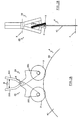
Figs. 1A, 1B schematically show a device in accordance with the present invention associated with a blade in a waiting configuration, represented, respectively, in a side view (Fig.1A ) and a front view (Fig.1B ), with parts removed and/or sectioned to better illustrate other parts; -
Figs. 2A, 2B schematically show the present device in an active configuration, represented, respectively, in a side view (Fig.2A ) and a front view (Fig.2B ), with parts removed and / or sectioned to better illustrate others; -
Fig.3 represents a further embodiment of a device according to the invention in the active configuration; -
Fig.4 represents the device ofFig.3 in the rest configuration. - With reference to the attached drawings (in particular,
Figs. 1A to 2B ), a device (1) in accordance with the present invention can be used for sharpening blades, in particular for a cutting machine provided with a blade (4). The blade (4) is provided with two inclined parts (bevels) that, joining with each other, form the sharp edge or cutting edge (40). - The device (1) comprises two grinding wheels (2, 3) supported by corresponding movable arms (20, 30) which, on command, move said grinding wheels (2, 3) in contact with said sharp edge (40) to perform a sharpening operation.
- Said arms (20, 30) are fulcrated to each other so as to define a first-class double lever like scissors, with resistant force consisting in the friction generated by the contact of the grinding wheels (2, 3) with the blade (4). The fulcrum of the double lever formed by the arms (20, 30) has an axis (x) perpendicular to the cutting plane (P) defined by the sharp edge (40) of the blade (4). Said axis (x) is external to the blade and is parallel to a rotation axis (y) of the latter. The distal portions (L20, L30) of the arms (20, 30) have a length whose value is such that the grinding wheels (2, 3) can be moved along corresponding trajectories interfering with the sharp edge (40) of the blade (4) so as to allow sharpening as further described in the following.
- The block (M) in the drawings represents motor means acting on the proximal portions (200, 300) of said arms (20, 30) so as to constitute the force applied to the double lever formed by the same arms. The motor means (M) act bi-directionally so as to move the proximal portions (200, 300) of the arms (20, 30) towards or away from each other, thereby moving the distal portions of the arms that support the wheels (2, 3).
- In practice, the device can have at least two configurations: a standby or rest configuration, shown in Figg.1A and 1B, and an active configuration, shown in
Figures 2a and 2B . In the standby or rest configuration, the motor means (M) are not activated and maintain the proximal portions (200, 300) of the arms (20, 30) spaced from each other. Once activated, the motor means (M) move the proximal portions (200, 300) of the arms (20, 30) towards each other, determining the corresponding approaching of the distal portions (201, 301) that support the grinding wheels (2, 3). - Consequently, each of the grinding wheels (2, 3) follows a trajectory having the shape of circular arc (indicated with R2 and R3 in
Fig.1B ) which carries the same grinding wheels in contact with the blade (4) to perform sharpening. This trajectory allows a continuous and gradual approach of the grinding wheels to the respective sides of the blade (4). In other words, the contact of each grinding wheel (2, 3) with the respective side of the cutting edge of the blade (4) is progressive, whereby the contact area between the grinding wheels and the blade increases progressively when the device passes from the rest configuration to the active configuration. Hence, a better blade sharpening is achieved and the structural integrity of the blade is preserved. - According to the example shown in the drawings, the axis of said circular arcs (R2, R3) coincides with the afore-mentioned axis (x) and each arc (R2, R3) is parallel to said cutting plane (P). Therefore, when moved by the arms (20, 30), the grinding wheels (2, 3) run along respective arcuate trajectories (R2, R3) parallel to the sides (41) of the blade (4).
- Said arms (20, 30) can be advantageously connected with suitable pressure sensors adapted to detect the pressure exerted by each wheel (2, 3) on the respective side of the blade (4). Furthermore, said pressure sensors can be connected to the motor means (M), by means of a corresponding control unit, to control the action of the same motor means (M) on the arms (20, 30), i.e. to control the pressure exerted by the grinding wheels (2, 3) on the blade (4). In other words, a device in accordance with the present invention can be provided with means for controlling the pressure exerted by the grinding wheels (2, 3) on the blade (4).
- Advantageously, the device (1) can be connected with a control device adapted for controlling the sharpening of the blade (4) that, in turn, can be connected with said motor means (M). In this way it is possible to obtain an automatic sharpening of the blade (4) when the control device detects a not correct sharpening.
- Furthermore, preferably, said grinding wheels and the related arms are identical and placed in symmetrical positions with respect to the cutting plane of the blade, so as to determine an identical behavior of the two grinding wheels on both sides of the blade.
- With reference to the example shown in
Fig.3 andFig.4 , two identical springs (S) are provided, acting each on a respective arm (20,30). A single motor means is used to simultaneously operate the arms (20, 30) that support the two grinding wheels. The movement of the grinding wheels according to the examples given above is such as to bring the grinding wheels in a defined position so that there is always a fixed geometric interference between the grinding wheels and the blade, or there is always a fixed pressure exerted by the grinding wheels on the blade. In practice, the details of execution may vary in any equivalent way as in the shape, dimensions, elements disposition, nature of the materials used, within the scope of the appended claims.
Claims (10)
- Sharpening device for sharpening blades mounted on cutting machines, comprising two grinding wheels (2, 3) supported by respective movable supports (20, 30) adapted to move said grinding wheels (2, 3) from a standby or rest configuration in which the grinding wheels (2, 3) are positioned at a predetermined distance from a blade (4) having a cutting edge (40) and two opposite sides (41) between which the cutting edge is comprised to an active configuration in which the grinding wheels (2, 3) are in contact with said cutting edge (40) and vice-versa along a predetermined trajectory, characterized in that said movable supports (20, 30) are adapted to move said grinding wheels (2, 3) along respective arcuate trajectories (R2, R3) parallel to the opposite sides of the blade (4), such that the contact of each grinding wheel (2, 3) with a respective side of the cutting edge (40) of the blade (4) is progressive, whereby the contact between the grinding wheels and the blade increases progressively when the device passes from the standby or rest configuration to the active configuration.
- Sharpening device according to claim 1, characterized in that said movable supports (20, 30) are hinged to each other so as to define a double lever with resisting force defined by the friction generated by the contact of the grinding wheels (2, 3) with the blade (4).
- Sharpening device according to claim 2, characterized in that the fulcrum of said lever has an axis (x) perpendicular to a plane that is defined by the blade (4) and is external to the same blade.
- Sharpening device according to claim 2, characterized in that it comprises actuating means (M) acting on said movable supports (20, 30), said means (M) acting bi-directionally so as to approach or distance the proximal portions of said movable supports, that is, to respectively distance or approach the corresponding distal portions (201, 301) of the movable supports supporting the said grinding wheels (2, 3).
- Sharpening device according to claim 4, characterized in that said means (M) for moving the movable supports (20, 30) are connected to a control device that controls the state of sharpening of the blade (4).
- Sharpening device according to claim 4, characterized in that said actuating means control the pressure exerted by the grinding wheels (2, 3) on the blade (4).
- Sharpening device according to claims 1 and 4, characterized in that said actuating means control the position of the grinding wheels (2, 3) with respect to the blade (4).
- Sharpening device according to claim 1, characterized in that on each of said movable supports (20, 30) is arranged a corresponding traction or compression spring (S).
- Sharpening device according to claim 8 characterized in that said springs (S) are identical to each other.
- Sharpening device according to claim 8, characterized in that said springs (S) exert a same thrust on said movable supports (20, 30).
Priority Applications (2)
| Application Number | Priority Date | Filing Date | Title |
|---|---|---|---|
| PL14809531T PL3077157T3 (en) | 2013-12-02 | 2014-10-17 | Device for sharpening blades |
| RS20170850A RS56237B1 (en) | 2013-12-02 | 2014-10-17 | Blades sharpener |
Applications Claiming Priority (2)
| Application Number | Priority Date | Filing Date | Title |
|---|---|---|---|
| IT000294A ITFI20130294A1 (en) | 2013-12-02 | 2013-12-02 | SHARPENING DEVICE. |
| PCT/IT2014/000273 WO2015083188A1 (en) | 2013-12-02 | 2014-10-17 | Device for sharpening blades |
Publications (2)
| Publication Number | Publication Date |
|---|---|
| EP3077157A1 EP3077157A1 (en) | 2016-10-12 |
| EP3077157B1 true EP3077157B1 (en) | 2017-07-19 |
Family
ID=49887056
Family Applications (1)
| Application Number | Title | Priority Date | Filing Date |
|---|---|---|---|
| EP14809531.8A Active EP3077157B1 (en) | 2013-12-02 | 2014-10-17 | Device for sharpening blades |
Country Status (11)
| Country | Link |
|---|---|
| US (1) | US10035235B2 (en) |
| EP (1) | EP3077157B1 (en) |
| JP (1) | JP6298531B2 (en) |
| CN (1) | CN105682857B (en) |
| BR (1) | BR112016009379B1 (en) |
| ES (1) | ES2639806T3 (en) |
| IT (1) | ITFI20130294A1 (en) |
| PL (1) | PL3077157T3 (en) |
| RS (1) | RS56237B1 (en) |
| RU (1) | RU2655872C1 (en) |
| WO (1) | WO2015083188A1 (en) |
Families Citing this family (9)
| Publication number | Priority date | Publication date | Assignee | Title |
|---|---|---|---|---|
| JP6548507B2 (en) * | 2015-08-10 | 2019-07-24 | 有限会社高芝ギムネ製作所 | Polisher |
| IT201700081306A1 (en) | 2017-07-18 | 2019-01-18 | Perini Fabio Spa | SHARPENING UNIT FOR A CUTTING BLADE, MACHINE INCLUDING SUCH GROUP AND METHOD |
| IT201700081320A1 (en) | 2017-07-18 | 2019-01-18 | Perini Fabio Spa | SHARPENING UNIT FOR CUTTING MACHINE AND MACHINE INCLUDING SUCH GROUP |
| SE542842C2 (en) * | 2019-03-13 | 2020-07-14 | Tore Eklund | Grinding and polishing tools, tool set, and attachment for circular cutting blade |
| US11192217B2 (en) * | 2019-05-17 | 2021-12-07 | Darex, Llc | Tool sharpener with tiltable sharpening stage |
| CN112059749B (en) * | 2020-09-22 | 2021-12-07 | 江苏宏元达光伏新材料有限公司 | Aluminum alloy razor head grinding device |
| CN112091735A (en) * | 2020-09-22 | 2020-12-18 | 侯仕仙 | Polishing device for small tool bit |
| CN113348863B (en) * | 2021-07-13 | 2023-09-01 | 吴雪原 | Tree leaf picking machine |
| US12434352B2 (en) * | 2023-08-09 | 2025-10-07 | Shiji Qu | Knife sharpener and knife sharpening device |
Family Cites Families (29)
| Publication number | Priority date | Publication date | Assignee | Title |
|---|---|---|---|---|
| US1039210A (en) * | 1912-06-12 | 1912-09-24 | Us Slicing Machine Co | Sharpening device for knives of meat-slicing machines. |
| US1129736A (en) * | 1913-10-13 | 1915-02-23 | George J Sayer | Device for sharpening rotary blades. |
| US1263450A (en) * | 1914-06-16 | 1918-04-23 | Hyman Maimin | Sharpening attachment for cloth-cutting machines. |
| US1165342A (en) * | 1915-02-19 | 1915-12-21 | George J Saver | Sharpener for rotary blades. |
| US1907585A (en) * | 1926-12-17 | 1933-05-09 | Us Slicing Machine Co | Sharpener for slicing machine knives |
| GB500678A (en) * | 1937-03-09 | 1939-02-14 | Fernand Louis Broussouse | Improved device for sharpening knives and like cutting blades |
| US2632289A (en) * | 1948-06-18 | 1953-03-24 | Ditting Adolf | Device for sharpening the blades of slicing machines for slicing eatables |
| SU82341A1 (en) * | 1949-05-11 | 1949-11-30 | Н.Г. Фетисов | Polishing machine for dangerous razors |
| US2597325A (en) * | 1950-09-25 | 1952-05-20 | Hodges Mfg Co | Cultivator disk sharpener |
| US3010261A (en) * | 1958-05-24 | 1961-11-28 | Hauni Werke Koerber & Co Kg | Machines for cutting cigarettes, cigarillos, filter components or the like having a rotary cutter and a grinder therefor |
| JPS5016159Y1 (en) * | 1969-04-25 | 1975-05-20 | ||
| US4173846A (en) * | 1978-01-23 | 1979-11-13 | Paper Converting Machine Company | Orbital saw sharpening device |
| US4262452A (en) * | 1978-11-24 | 1981-04-21 | Lopez Francisco R | Disc brake grinding apparatus and method |
| JPS5669067A (en) * | 1979-11-06 | 1981-06-10 | Taihei Mach Works Ltd | Method and apparatus for superfinishing share point |
| US4584917A (en) * | 1984-12-06 | 1986-04-29 | Paper Converting Machine Company | Automatic blade diameter compensation for log saws |
| IT1233279B (en) * | 1989-04-05 | 1992-03-26 | Perini Finanziaria Spa | CUTTING MACHINE FOR CUTTING STICKS OF PAPER AND SIMILAR MATERIAL |
| US5906534A (en) * | 1998-01-14 | 1999-05-25 | Leatherman Tool Group, Inc. | Sharpening a knife blade |
| ITFI20020155A1 (en) * | 2002-08-09 | 2004-02-10 | Fabio Perini | DEVICE FOR TRIMMING STICKS OF PAPER OR "LOGS" AND OPERATING METHOD FOR THE TREATMENT OF LOGS |
| ITFI20020207A1 (en) * | 2002-10-30 | 2004-04-30 | Perini Fabio Spa | SHARPENING GROUP AND CUTTING MACHINE INCLUDING AT LEAST ONE BLADE AND SAID SHARPENING GROUP |
| CN201095053Y (en) * | 2007-10-23 | 2008-08-06 | 张家港市德顺机械有限责任公司 | Automatic knife grinding device |
| US7857681B2 (en) * | 2008-05-01 | 2010-12-28 | Bonapace Mario J | Automatic rotation knife sharpener |
| CN201619010U (en) * | 2010-02-22 | 2010-11-03 | 杭州钱江弹簧有限公司 | Grinding device for leveling two end surfaces of arc spring |
| US8535120B2 (en) * | 2010-08-31 | 2013-09-17 | Cnh America Llc | Blade sharpening system for agricultural implements |
| US20120184186A1 (en) * | 2011-01-14 | 2012-07-19 | Graham Jr Dave | Blade sharpening system and method |
| EP2532477B1 (en) * | 2011-06-06 | 2019-04-24 | Weber Maschinenbau GmbH Breidenbach | Method and device for grinding rotation blades |
| CN202292301U (en) * | 2011-09-30 | 2012-07-04 | 浙江理工大学 | Semiautomatic simple tooth type disc blade sharpening device |
| US8926408B2 (en) * | 2012-05-03 | 2015-01-06 | Tom Hiroshi Hasegawa | Blade sharpener |
| CN203156468U (en) * | 2013-01-30 | 2013-08-28 | 龙岩烟草工业有限责任公司 | Grinding wheel spindle assembly and knife grinder |
| US9227288B2 (en) * | 2013-03-15 | 2016-01-05 | Sca Hygiene Products Ab | Blade honing apparatus and cutting apparatus incorporating same |
-
2013
- 2013-12-02 IT IT000294A patent/ITFI20130294A1/en unknown
-
2014
- 2014-10-17 RU RU2016126409A patent/RU2655872C1/en active
- 2014-10-17 US US15/038,842 patent/US10035235B2/en active Active
- 2014-10-17 EP EP14809531.8A patent/EP3077157B1/en active Active
- 2014-10-17 CN CN201480058231.6A patent/CN105682857B/en active Active
- 2014-10-17 JP JP2016534182A patent/JP6298531B2/en active Active
- 2014-10-17 WO PCT/IT2014/000273 patent/WO2015083188A1/en not_active Ceased
- 2014-10-17 BR BR112016009379-8A patent/BR112016009379B1/en active IP Right Grant
- 2014-10-17 PL PL14809531T patent/PL3077157T3/en unknown
- 2014-10-17 RS RS20170850A patent/RS56237B1/en unknown
- 2014-10-17 ES ES14809531.8T patent/ES2639806T3/en active Active
Non-Patent Citations (1)
| Title |
|---|
| None * |
Also Published As
| Publication number | Publication date |
|---|---|
| CN105682857A (en) | 2016-06-15 |
| ES2639806T3 (en) | 2017-10-30 |
| EP3077157A1 (en) | 2016-10-12 |
| US20170036316A1 (en) | 2017-02-09 |
| PL3077157T3 (en) | 2017-12-29 |
| JP6298531B2 (en) | 2018-03-20 |
| CN105682857B (en) | 2017-11-14 |
| RU2655872C1 (en) | 2018-05-29 |
| ITFI20130294A1 (en) | 2015-06-03 |
| JP2016538144A (en) | 2016-12-08 |
| BR112016009379B1 (en) | 2020-11-24 |
| WO2015083188A1 (en) | 2015-06-11 |
| RS56237B1 (en) | 2017-11-30 |
| US10035235B2 (en) | 2018-07-31 |
Similar Documents
| Publication | Publication Date | Title |
|---|---|---|
| US10035235B2 (en) | Device for sharpening blades | |
| US10029380B2 (en) | Control device for blades sharpening | |
| JP4936396B2 (en) | Incision creasing wheel assembly and method for incising and creasing compressible material | |
| EP4065321B1 (en) | Cutting machine for transversely cutting logs of paper material | |
| EP3074179B1 (en) | Device for sharpening blades | |
| CA3062557A1 (en) | Method for cross-cutting a material web moved in a direction of movement, and device therefor | |
| EP4065320B1 (en) | Cutting machine for transversely cutting logs of paper | |
| EP2921256B1 (en) | Cutting machine with grinding unit | |
| JP2022536897A (en) | Cutting machine for paper rolls with grinding device | |
| US20240109218A1 (en) | Cutting-off machine for the transversal cutting of logs of paper material | |
| JP2022536899A (en) | paper material log cutting machine with grinder | |
| RU2621494C1 (en) | Device for roll paper slitting cut | |
| CN110498274A (en) | The infeed set-up of up- coiler | |
| US20160194169A1 (en) | Device and method for controlling the separation of sheets of paper webs in rewinding machines and a rewinding machine provided with such a device | |
| JP2003117883A (en) | Log brake in log cutting machine |
Legal Events
| Date | Code | Title | Description |
|---|---|---|---|
| PUAI | Public reference made under article 153(3) epc to a published international application that has entered the european phase |
Free format text: ORIGINAL CODE: 0009012 |
|
| 17P | Request for examination filed |
Effective date: 20160413 |
|
| AK | Designated contracting states |
Kind code of ref document: A1 Designated state(s): AL AT BE BG CH CY CZ DE DK EE ES FI FR GB GR HR HU IE IS IT LI LT LU LV MC MK MT NL NO PL PT RO RS SE SI SK SM TR |
|
| AX | Request for extension of the european patent |
Extension state: BA ME |
|
| DAX | Request for extension of the european patent (deleted) | ||
| GRAP | Despatch of communication of intention to grant a patent |
Free format text: ORIGINAL CODE: EPIDOSNIGR1 |
|
| INTG | Intention to grant announced |
Effective date: 20170410 |
|
| GRAS | Grant fee paid |
Free format text: ORIGINAL CODE: EPIDOSNIGR3 |
|
| GRAA | (expected) grant |
Free format text: ORIGINAL CODE: 0009210 |
|
| AK | Designated contracting states |
Kind code of ref document: B1 Designated state(s): AL AT BE BG CH CY CZ DE DK EE ES FI FR GB GR HR HU IE IS IT LI LT LU LV MC MK MT NL NO PL PT RO RS SE SI SK SM TR |
|
| REG | Reference to a national code |
Ref country code: GB Ref legal event code: FG4D |
|
| REG | Reference to a national code |
Ref country code: CH Ref legal event code: EP |
|
| REG | Reference to a national code |
Ref country code: IE Ref legal event code: FG4D |
|
| REG | Reference to a national code |
Ref country code: AT Ref legal event code: REF Ref document number: 909929 Country of ref document: AT Kind code of ref document: T Effective date: 20170815 |
|
| REG | Reference to a national code |
Ref country code: RO Ref legal event code: EPE |
|
| REG | Reference to a national code |
Ref country code: DE Ref legal event code: R096 Ref document number: 602014012115 Country of ref document: DE |
|
| REG | Reference to a national code |
Ref country code: SE Ref legal event code: TRGR |
|
| REG | Reference to a national code |
Ref country code: FR Ref legal event code: PLFP Year of fee payment: 4 |
|
| REG | Reference to a national code |
Ref country code: ES Ref legal event code: FG2A Ref document number: 2639806 Country of ref document: ES Kind code of ref document: T3 Effective date: 20171030 |
|
| REG | Reference to a national code |
Ref country code: NL Ref legal event code: MP Effective date: 20170719 |
|
| REG | Reference to a national code |
Ref country code: LT Ref legal event code: MG4D |
|
| REG | Reference to a national code |
Ref country code: AT Ref legal event code: MK05 Ref document number: 909929 Country of ref document: AT Kind code of ref document: T Effective date: 20170719 |
|
| PG25 | Lapsed in a contracting state [announced via postgrant information from national office to epo] |
Ref country code: LT Free format text: LAPSE BECAUSE OF FAILURE TO SUBMIT A TRANSLATION OF THE DESCRIPTION OR TO PAY THE FEE WITHIN THE PRESCRIBED TIME-LIMIT Effective date: 20170719 Ref country code: HR Free format text: LAPSE BECAUSE OF FAILURE TO SUBMIT A TRANSLATION OF THE DESCRIPTION OR TO PAY THE FEE WITHIN THE PRESCRIBED TIME-LIMIT Effective date: 20170719 Ref country code: NL Free format text: LAPSE BECAUSE OF FAILURE TO SUBMIT A TRANSLATION OF THE DESCRIPTION OR TO PAY THE FEE WITHIN THE PRESCRIBED TIME-LIMIT Effective date: 20170719 Ref country code: NO Free format text: LAPSE BECAUSE OF FAILURE TO SUBMIT A TRANSLATION OF THE DESCRIPTION OR TO PAY THE FEE WITHIN THE PRESCRIBED TIME-LIMIT Effective date: 20171019 Ref country code: AT Free format text: LAPSE BECAUSE OF FAILURE TO SUBMIT A TRANSLATION OF THE DESCRIPTION OR TO PAY THE FEE WITHIN THE PRESCRIBED TIME-LIMIT Effective date: 20170719 |
|
| PG25 | Lapsed in a contracting state [announced via postgrant information from national office to epo] |
Ref country code: LV Free format text: LAPSE BECAUSE OF FAILURE TO SUBMIT A TRANSLATION OF THE DESCRIPTION OR TO PAY THE FEE WITHIN THE PRESCRIBED TIME-LIMIT Effective date: 20170719 Ref country code: GR Free format text: LAPSE BECAUSE OF FAILURE TO SUBMIT A TRANSLATION OF THE DESCRIPTION OR TO PAY THE FEE WITHIN THE PRESCRIBED TIME-LIMIT Effective date: 20171020 Ref country code: IS Free format text: LAPSE BECAUSE OF FAILURE TO SUBMIT A TRANSLATION OF THE DESCRIPTION OR TO PAY THE FEE WITHIN THE PRESCRIBED TIME-LIMIT Effective date: 20171119 Ref country code: BG Free format text: LAPSE BECAUSE OF FAILURE TO SUBMIT A TRANSLATION OF THE DESCRIPTION OR TO PAY THE FEE WITHIN THE PRESCRIBED TIME-LIMIT Effective date: 20171019 |
|
| REG | Reference to a national code |
Ref country code: DE Ref legal event code: R097 Ref document number: 602014012115 Country of ref document: DE |
|
| PG25 | Lapsed in a contracting state [announced via postgrant information from national office to epo] |
Ref country code: CZ Free format text: LAPSE BECAUSE OF FAILURE TO SUBMIT A TRANSLATION OF THE DESCRIPTION OR TO PAY THE FEE WITHIN THE PRESCRIBED TIME-LIMIT Effective date: 20170719 Ref country code: DK Free format text: LAPSE BECAUSE OF FAILURE TO SUBMIT A TRANSLATION OF THE DESCRIPTION OR TO PAY THE FEE WITHIN THE PRESCRIBED TIME-LIMIT Effective date: 20170719 |
|
| PLBE | No opposition filed within time limit |
Free format text: ORIGINAL CODE: 0009261 |
|
| STAA | Information on the status of an ep patent application or granted ep patent |
Free format text: STATUS: NO OPPOSITION FILED WITHIN TIME LIMIT |
|
| PG25 | Lapsed in a contracting state [announced via postgrant information from national office to epo] |
Ref country code: SK Free format text: LAPSE BECAUSE OF FAILURE TO SUBMIT A TRANSLATION OF THE DESCRIPTION OR TO PAY THE FEE WITHIN THE PRESCRIBED TIME-LIMIT Effective date: 20170719 Ref country code: EE Free format text: LAPSE BECAUSE OF FAILURE TO SUBMIT A TRANSLATION OF THE DESCRIPTION OR TO PAY THE FEE WITHIN THE PRESCRIBED TIME-LIMIT Effective date: 20170719 Ref country code: MC Free format text: LAPSE BECAUSE OF FAILURE TO SUBMIT A TRANSLATION OF THE DESCRIPTION OR TO PAY THE FEE WITHIN THE PRESCRIBED TIME-LIMIT Effective date: 20170719 Ref country code: SM Free format text: LAPSE BECAUSE OF FAILURE TO SUBMIT A TRANSLATION OF THE DESCRIPTION OR TO PAY THE FEE WITHIN THE PRESCRIBED TIME-LIMIT Effective date: 20170719 |
|
| REG | Reference to a national code |
Ref country code: CH Ref legal event code: PL |
|
| 26N | No opposition filed |
Effective date: 20180420 |
|
| REG | Reference to a national code |
Ref country code: IE Ref legal event code: MM4A |
|
| PG25 | Lapsed in a contracting state [announced via postgrant information from national office to epo] |
Ref country code: LI Free format text: LAPSE BECAUSE OF NON-PAYMENT OF DUE FEES Effective date: 20171031 Ref country code: CH Free format text: LAPSE BECAUSE OF NON-PAYMENT OF DUE FEES Effective date: 20171031 Ref country code: LU Free format text: LAPSE BECAUSE OF NON-PAYMENT OF DUE FEES Effective date: 20171017 |
|
| REG | Reference to a national code |
Ref country code: BE Ref legal event code: MM Effective date: 20171031 |
|
| PG25 | Lapsed in a contracting state [announced via postgrant information from national office to epo] |
Ref country code: BE Free format text: LAPSE BECAUSE OF NON-PAYMENT OF DUE FEES Effective date: 20171031 Ref country code: SI Free format text: LAPSE BECAUSE OF FAILURE TO SUBMIT A TRANSLATION OF THE DESCRIPTION OR TO PAY THE FEE WITHIN THE PRESCRIBED TIME-LIMIT Effective date: 20170719 |
|
| PG25 | Lapsed in a contracting state [announced via postgrant information from national office to epo] |
Ref country code: MT Free format text: LAPSE BECAUSE OF NON-PAYMENT OF DUE FEES Effective date: 20171017 |
|
| REG | Reference to a national code |
Ref country code: FR Ref legal event code: PLFP Year of fee payment: 5 |
|
| PG25 | Lapsed in a contracting state [announced via postgrant information from national office to epo] |
Ref country code: IE Free format text: LAPSE BECAUSE OF NON-PAYMENT OF DUE FEES Effective date: 20171017 |
|
| PG25 | Lapsed in a contracting state [announced via postgrant information from national office to epo] |
Ref country code: HU Free format text: LAPSE BECAUSE OF FAILURE TO SUBMIT A TRANSLATION OF THE DESCRIPTION OR TO PAY THE FEE WITHIN THE PRESCRIBED TIME-LIMIT; INVALID AB INITIO Effective date: 20141017 |
|
| PG25 | Lapsed in a contracting state [announced via postgrant information from national office to epo] |
Ref country code: CY Free format text: LAPSE BECAUSE OF FAILURE TO SUBMIT A TRANSLATION OF THE DESCRIPTION OR TO PAY THE FEE WITHIN THE PRESCRIBED TIME-LIMIT Effective date: 20170719 |
|
| PG25 | Lapsed in a contracting state [announced via postgrant information from national office to epo] |
Ref country code: MK Free format text: LAPSE BECAUSE OF FAILURE TO SUBMIT A TRANSLATION OF THE DESCRIPTION OR TO PAY THE FEE WITHIN THE PRESCRIBED TIME-LIMIT Effective date: 20170719 |
|
| PG25 | Lapsed in a contracting state [announced via postgrant information from national office to epo] |
Ref country code: PT Free format text: LAPSE BECAUSE OF FAILURE TO SUBMIT A TRANSLATION OF THE DESCRIPTION OR TO PAY THE FEE WITHIN THE PRESCRIBED TIME-LIMIT Effective date: 20170719 |
|
| PG25 | Lapsed in a contracting state [announced via postgrant information from national office to epo] |
Ref country code: AL Free format text: LAPSE BECAUSE OF FAILURE TO SUBMIT A TRANSLATION OF THE DESCRIPTION OR TO PAY THE FEE WITHIN THE PRESCRIBED TIME-LIMIT Effective date: 20170719 |
|
| PGFP | Annual fee paid to national office [announced via postgrant information from national office to epo] |
Ref country code: IT Payment date: 20250811 Year of fee payment: 12 |
|
| PGFP | Annual fee paid to national office [announced via postgrant information from national office to epo] |
Ref country code: DE Payment date: 20251021 Year of fee payment: 12 |
|
| PGFP | Annual fee paid to national office [announced via postgrant information from national office to epo] |
Ref country code: GB Payment date: 20251022 Year of fee payment: 12 |
|
| PGFP | Annual fee paid to national office [announced via postgrant information from national office to epo] |
Ref country code: FI Payment date: 20251028 Year of fee payment: 12 |
|
| PGFP | Annual fee paid to national office [announced via postgrant information from national office to epo] |
Ref country code: FR Payment date: 20251030 Year of fee payment: 12 |
|
| PGFP | Annual fee paid to national office [announced via postgrant information from national office to epo] |
Ref country code: TR Payment date: 20251013 Year of fee payment: 12 |
|
| PGFP | Annual fee paid to national office [announced via postgrant information from national office to epo] |
Ref country code: SE Payment date: 20251021 Year of fee payment: 12 |
|
| PGFP | Annual fee paid to national office [announced via postgrant information from national office to epo] |
Ref country code: PL Payment date: 20251010 Year of fee payment: 12 |
|
| PGFP | Annual fee paid to national office [announced via postgrant information from national office to epo] |
Ref country code: RO Payment date: 20251013 Year of fee payment: 12 |
|
| PGFP | Annual fee paid to national office [announced via postgrant information from national office to epo] |
Ref country code: RS Payment date: 20251009 Year of fee payment: 12 |
|
| PGFP | Annual fee paid to national office [announced via postgrant information from national office to epo] |
Ref country code: ES Payment date: 20251210 Year of fee payment: 12 |