EP3076897B1 - Système de détermination de la surface de contact et de la répartition des forces occlusales entre les dents d'une machoire de patient et procédé correspondant - Google Patents
Système de détermination de la surface de contact et de la répartition des forces occlusales entre les dents d'une machoire de patient et procédé correspondant Download PDFInfo
- Publication number
- EP3076897B1 EP3076897B1 EP14821793.8A EP14821793A EP3076897B1 EP 3076897 B1 EP3076897 B1 EP 3076897B1 EP 14821793 A EP14821793 A EP 14821793A EP 3076897 B1 EP3076897 B1 EP 3076897B1
- Authority
- EP
- European Patent Office
- Prior art keywords
- layer
- teeth
- patient
- electrodes
- thickness
- Prior art date
- Legal status (The legal status is an assumption and is not a legal conclusion. Google has not performed a legal analysis and makes no representation as to the accuracy of the status listed.)
- Not-in-force
Links
- 238000009826 distribution Methods 0.000 title claims description 14
- 238000000034 method Methods 0.000 title claims description 14
- 239000000463 material Substances 0.000 claims description 15
- 238000013507 mapping Methods 0.000 claims description 14
- 239000004065 semiconductor Substances 0.000 claims description 9
- 229910052782 aluminium Inorganic materials 0.000 claims description 7
- XAGFODPZIPBFFR-UHFFFAOYSA-N aluminium Chemical compound [Al] XAGFODPZIPBFFR-UHFFFAOYSA-N 0.000 claims description 7
- 230000008021 deposition Effects 0.000 claims description 7
- 229910052751 metal Inorganic materials 0.000 claims description 6
- 239000002184 metal Substances 0.000 claims description 6
- 229910021424 microcrystalline silicon Inorganic materials 0.000 claims description 6
- 229920002457 flexible plastic Polymers 0.000 claims description 5
- 229910052710 silicon Inorganic materials 0.000 claims description 5
- 239000010703 silicon Substances 0.000 claims description 5
- 239000004411 aluminium Substances 0.000 claims description 2
- 239000010410 layer Substances 0.000 description 58
- 238000005259 measurement Methods 0.000 description 25
- 238000000151 deposition Methods 0.000 description 10
- HQVNEWCFYHHQES-UHFFFAOYSA-N silicon nitride Chemical compound N12[Si]34N5[Si]62N3[Si]51N64 HQVNEWCFYHHQES-UHFFFAOYSA-N 0.000 description 8
- 229910052581 Si3N4 Inorganic materials 0.000 description 7
- XUIMIQQOPSSXEZ-UHFFFAOYSA-N Silicon Chemical compound [Si] XUIMIQQOPSSXEZ-UHFFFAOYSA-N 0.000 description 6
- 230000006870 function Effects 0.000 description 6
- 239000011112 polyethylene naphthalate Substances 0.000 description 5
- 238000001020 plasma etching Methods 0.000 description 4
- 238000000623 plasma-assisted chemical vapour deposition Methods 0.000 description 4
- 229920003207 poly(ethylene-2,6-naphthalate) Polymers 0.000 description 4
- 230000036346 tooth eruption Effects 0.000 description 4
- NBIIXXVUZAFLBC-UHFFFAOYSA-N Phosphoric acid Chemical compound OP(O)(O)=O NBIIXXVUZAFLBC-UHFFFAOYSA-N 0.000 description 3
- 229910018503 SF6 Inorganic materials 0.000 description 3
- 230000015572 biosynthetic process Effects 0.000 description 3
- 239000000919 ceramic Substances 0.000 description 3
- 210000004513 dentition Anatomy 0.000 description 3
- 239000007943 implant Substances 0.000 description 3
- 238000000206 photolithography Methods 0.000 description 3
- 239000002985 plastic film Substances 0.000 description 3
- 239000000758 substrate Substances 0.000 description 3
- SFZCNBIFKDRMGX-UHFFFAOYSA-N sulfur hexafluoride Chemical compound FS(F)(F)(F)(F)F SFZCNBIFKDRMGX-UHFFFAOYSA-N 0.000 description 3
- 229960000909 sulfur hexafluoride Drugs 0.000 description 3
- CSCPPACGZOOCGX-UHFFFAOYSA-N Acetone Chemical compound CC(C)=O CSCPPACGZOOCGX-UHFFFAOYSA-N 0.000 description 2
- LFQSCWFLJHTTHZ-UHFFFAOYSA-N Ethanol Chemical compound CCO LFQSCWFLJHTTHZ-UHFFFAOYSA-N 0.000 description 2
- KFZMGEQAYNKOFK-UHFFFAOYSA-N Isopropanol Chemical compound CC(C)O KFZMGEQAYNKOFK-UHFFFAOYSA-N 0.000 description 2
- 238000003491 array Methods 0.000 description 2
- 229910052785 arsenic Inorganic materials 0.000 description 2
- RQNWIZPPADIBDY-UHFFFAOYSA-N arsenic atom Chemical compound [As] RQNWIZPPADIBDY-UHFFFAOYSA-N 0.000 description 2
- 230000006399 behavior Effects 0.000 description 2
- 230000001055 chewing effect Effects 0.000 description 2
- 230000000295 complement effect Effects 0.000 description 2
- 238000001514 detection method Methods 0.000 description 2
- 208000037265 diseases, disorders, signs and symptoms Diseases 0.000 description 2
- 239000012777 electrically insulating material Substances 0.000 description 2
- 238000005530 etching Methods 0.000 description 2
- 230000008020 evaporation Effects 0.000 description 2
- 238000001704 evaporation Methods 0.000 description 2
- 238000004519 manufacturing process Methods 0.000 description 2
- 235000011007 phosphoric acid Nutrition 0.000 description 2
- 230000003252 repetitive effect Effects 0.000 description 2
- 238000001039 wet etching Methods 0.000 description 2
- QYKABQMBXCBINA-UHFFFAOYSA-N 4-(oxan-2-yloxy)benzaldehyde Chemical compound C1=CC(C=O)=CC=C1OC1OCCCC1 QYKABQMBXCBINA-UHFFFAOYSA-N 0.000 description 1
- IJGRMHOSHXDMSA-UHFFFAOYSA-N Atomic nitrogen Chemical compound N#N IJGRMHOSHXDMSA-UHFFFAOYSA-N 0.000 description 1
- 206010019233 Headaches Diseases 0.000 description 1
- 239000004642 Polyimide Substances 0.000 description 1
- 229910004298 SiO 2 Inorganic materials 0.000 description 1
- BLRPTPMANUNPDV-UHFFFAOYSA-N Silane Chemical compound [SiH4] BLRPTPMANUNPDV-UHFFFAOYSA-N 0.000 description 1
- VYPSYNLAJGMNEJ-UHFFFAOYSA-N Silicium dioxide Chemical compound O=[Si]=O VYPSYNLAJGMNEJ-UHFFFAOYSA-N 0.000 description 1
- 206010043183 Teething Diseases 0.000 description 1
- 239000000853 adhesive Substances 0.000 description 1
- 229910000147 aluminium phosphate Inorganic materials 0.000 description 1
- 238000000137 annealing Methods 0.000 description 1
- 238000009530 blood pressure measurement Methods 0.000 description 1
- 239000003795 chemical substances by application Substances 0.000 description 1
- 238000004140 cleaning Methods 0.000 description 1
- 239000004020 conductor Substances 0.000 description 1
- 238000012937 correction Methods 0.000 description 1
- 230000007547 defect Effects 0.000 description 1
- 238000010586 diagram Methods 0.000 description 1
- 201000010099 disease Diseases 0.000 description 1
- 208000035475 disorder Diseases 0.000 description 1
- 239000012153 distilled water Substances 0.000 description 1
- 230000000694 effects Effects 0.000 description 1
- 238000000609 electron-beam lithography Methods 0.000 description 1
- 239000007789 gas Substances 0.000 description 1
- 239000008246 gaseous mixture Substances 0.000 description 1
- 239000007792 gaseous phase Substances 0.000 description 1
- 238000000227 grinding Methods 0.000 description 1
- 231100000869 headache Toxicity 0.000 description 1
- 239000001257 hydrogen Substances 0.000 description 1
- 229910052739 hydrogen Inorganic materials 0.000 description 1
- 125000004435 hydrogen atom Chemical class [H]* 0.000 description 1
- 238000003384 imaging method Methods 0.000 description 1
- 239000012535 impurity Substances 0.000 description 1
- 238000003780 insertion Methods 0.000 description 1
- 230000037431 insertion Effects 0.000 description 1
- 239000011810 insulating material Substances 0.000 description 1
- 125000001319 lambda(5)-arsanyl group Chemical group [H][As]([H])([H])([H])[*] 0.000 description 1
- 230000017074 necrotic cell death Effects 0.000 description 1
- 230000007935 neutral effect Effects 0.000 description 1
- 230000003287 optical effect Effects 0.000 description 1
- 210000000056 organ Anatomy 0.000 description 1
- 230000035515 penetration Effects 0.000 description 1
- 230000002093 peripheral effect Effects 0.000 description 1
- 239000004033 plastic Substances 0.000 description 1
- 229920003023 plastic Polymers 0.000 description 1
- 229920006255 plastic film Polymers 0.000 description 1
- 238000005498 polishing Methods 0.000 description 1
- 229920001721 polyimide Polymers 0.000 description 1
- 230000001144 postural effect Effects 0.000 description 1
- 238000012545 processing Methods 0.000 description 1
- 239000011241 protective layer Substances 0.000 description 1
- 229910000077 silane Inorganic materials 0.000 description 1
- 229910052814 silicon oxide Inorganic materials 0.000 description 1
- 238000005507 spraying Methods 0.000 description 1
- 230000003068 static effect Effects 0.000 description 1
- 238000012360 testing method Methods 0.000 description 1
- 230000000007 visual effect Effects 0.000 description 1
- XLYOFNOQVPJJNP-UHFFFAOYSA-N water Chemical compound O XLYOFNOQVPJJNP-UHFFFAOYSA-N 0.000 description 1
Images


Classifications
-
- A—HUMAN NECESSITIES
- A61—MEDICAL OR VETERINARY SCIENCE; HYGIENE
- A61C—DENTISTRY; APPARATUS OR METHODS FOR ORAL OR DENTAL HYGIENE
- A61C19/00—Dental auxiliary appliances
- A61C19/04—Measuring instruments specially adapted for dentistry
- A61C19/05—Measuring instruments specially adapted for dentistry for determining occlusion
-
- G—PHYSICS
- G01—MEASURING; TESTING
- G01L—MEASURING FORCE, STRESS, TORQUE, WORK, MECHANICAL POWER, MECHANICAL EFFICIENCY, OR FLUID PRESSURE
- G01L1/00—Measuring force or stress, in general
- G01L1/20—Measuring force or stress, in general by measuring variations in ohmic resistance of solid materials or of electrically-conductive fluids; by making use of electrokinetic cells, i.e. liquid-containing cells wherein an electrical potential is produced or varied upon the application of stress
- G01L1/205—Measuring force or stress, in general by measuring variations in ohmic resistance of solid materials or of electrically-conductive fluids; by making use of electrokinetic cells, i.e. liquid-containing cells wherein an electrical potential is produced or varied upon the application of stress using distributed sensing elements
Definitions
- the present invention relates to a system for determining the contact area and the distribution of the occlusal forces exerted between the upper teeth and the lower teeth of a patient's jaw, comprising a contact detecting member arranged between the teeth to be inserted between the teeth of the patient, connection elements of the detector member with means for calculating the distribution of the occlusal forces to perform the mapping and said calculating means.
- It also relates to a method implementing such a system and a removable flexible plate used with such a system.
- the invention finds a particularly important, although not exclusive, application in the field of dental impression taking and / or grinding (polishing) of the surfaces of the teeth coming into contact with one another in particular to ensure good dental occlusion.
- Good occlusion here means a good distribution of the pressure forces between the maxillary and mandibular teeth during chewing and / or when the patient tightens the jaws.
- the practitioner must ensure the patient's good dental occlusion. Specifically, the dentist must verify that the newly installed implant does not interfere with jaw movement and / or create residual internal pressure at rest.
- the dentist posing for example a prosthesis seeks to adjust it by trying to detect the hard points to file parts of the implant or teeth that interfere with good occlusion.
- Devices for detecting good occlusal contacts use substrates impregnated with colored agents released by chewing, commonly referred to as articulating paper, such as those marketed by the German company Bausch.
- None of these devices also determines the occlusion dynamically or allows to take a dental impression that can be stored in digital form and subsequently modified in time.
- determining the occlusion dynamically it is intended to measure the order of appearance of the occlusion points during movement of the jaw during an actual impression taking.
- Contact sensor devices are also known between two opposing objects ( EP 0 216 899 , WO89 / 02727 ) having an electrode assembly mounted on a support sheet.
- the present invention aims to overcome these disadvantages and proposes a device and a method that better than those previously known to the requirements of the practice, particularly in that it will allow reliable, repetitive measurements. , in the form of easily manipulated digital files, allowing comparisons and diagnoses hitherto impossible to achieve.
- the dentist will be able to accurately perform teething corrections of his patients, which will lead to comfort and a greatly improved health of the latter.
- the invention proposes in particular a system for determining the contact surface and the distribution of the forces exerted between the upper teeth and the lower teeth of a patient's jaw comprising a tooth contact detector member arranged to inserted between the teeth of the patient, connecting elements of the detector member with means for calculating the distribution of the occlusal forces to perform the mapping and said calculating means, characterized in that said detector member comprises a support piece of a removable flexible plate, said flexible plate being formed of a flexible plastic sheet secured to a pressure sensor grid comprising a first layer comprising a first network of electrodes called line electrodes, generally parallel, of a second intermediate layer of variable resistivity as a function of the pressure applied to it, and of a third layer comprising a second network of electrodes, called column electrodes, generally parallel, defining so-called intersection zones with the line electrodes, in that the sensor grid comprises at least 5000 intersecting areas adjacent to each other, of square section less than or equal to 600 micrometers, and in that the intermediate layer comprises a microcrystalline silicon semiconductor
- the layers and / or slices which are in general of different thicknesses are, on the other hand, of constant or substantially constant thicknesses.
- the invention also proposes a method for determining the contact area and the distribution of the occlusal forces of a patient's jaw, making it possible to obtain a mapping of said occlusal forces using a system as described above.
- the pressures are measured by means of said member provided with a sheet of flexible plastic material glued to a pressure sensor grid comprising at least 5000 sensors adjacent to each other. others, of square section less than or equal to 600 micro meters, said grid comprising an intermediate layer of variable resistivity as a function of pressure, said intermediate layer comprising a semicrocrystalline silicon wafer of thickness less than or equal to 50 nanometers, and the mapping of the occlusal forces to from the distribution of the measured pressures.
- mapping is dynamically displayed on a computer screen by integrating complementary data.
- the invention also relates to a removable flexible plate used with such a system and as described above.
- the plate is disposable.
- the figure 1 shows a system 1 for determining the contact area and the distribution of the occlusal forces between upper teeth 2 and lower teeth 3 of a jaw 4 of a patient 5.
- the system 1 comprises a detector member 6 of contacts between the teeth.
- This member 6 is inserted by the dentist (hand 7) between the teeth of the patient removably to detect the pressure field (arrow 7) when the jaw is tightened.
- the detector member 6 is connected, by connection means 8, comprising an electronic card 9 which will be detailed with reference to FIG. figure 5 with computing means 10 arranged to perform the mapping, dynamically represented by an image 11 on the screen of the computer 12.
- the detector member 6 comprises a support piece 13 of a removable flexible plate 14 whose constitution will now be described with reference to the figure 2 .
- the plate or piece 14 is flat, for example of parallelepipedal shape, of size 7 cm x 7 cm to be easily introduced into the patient's mouth and for example with a total thickness of the order of 800 microns.
- PEN polyethylene naphthalate
- flexible is meant a plate capable of accepting radii of curvature less than 1.5 mm.
- the support sheet 15 is substantially parallelepipedal, of dimension of the order of or less than that of the plate.
- the part 14 comprises a thin layer 18 of ceramic, for example 100 micrometers thick, bonded to the sheet or PEN 15, for example silicon nitride and of dimensions equal to those of the sheet 15.
- the assembly thus formed comprises on the top, a first layer 19 comprising a first array of electrodes 20, 20 ', called line electrodes.
- Each electrode is a metal wire for example of flattened rectangular section, elongate, electrical conductor for example aluminum.
- the width of the electrodes is less than 2 mm for example 0.5 mm and the thickness is for example between 150 nm and 500 nm, for example between 200 and 400, for example 300 nm.
- the electrode array is thus formed of a bundle of line electrodes substantially parallel to each other and spaced apart by a width of less than 2 mm, for example 0.25 mm.
- the row electrodes are in number greater than 100, for example 120, and operate in pairs 20, 20 '.
- Conducting elements 21 and 22 are also provided and will be detailed below.
- an intermediate layer 23 On the first layer 19 of line electrodes is placed an intermediate layer 23.
- This intermediate layer 23 comprises a semiconductor layer or wafer 24 of piezoelectric material.
- the piezoelectric material is semicrystalline silicon semiconductor (doped for example with arsenic).
- the wafer 24 covers with a substantially homogeneous thickness between 30 nm and 100 nm the portions 25 associated with the line electrode array and the space 26 between them, forming an electrical bridge between said parts which will be detailed below.
- the space between two pairs of line electrodes 20, 20 'does not have a layer of semiconductor material.
- the intermediate layer 21 further comprises a layer 27 of electrically insulating material over the semiconductor layer 24.
- the intermediate layer 27 thus formed is of variable resistivity as a function of the pressure and / or deformation applied thereto.
- the detector member 6 and more precisely the part 14 also comprises, above the intermediate layer 23, a third layer 29 comprising a second network of metal electrodes called column electrodes 30.
- the column electrodes 30 are for example similar to the row electrodes but arranged so that the superposition of said row and column arrays forms a grid.
- the two arrays are substantially orthogonal to each other, defining so-called intersection zones with the line electrodes to form the pressure sensors 17 bonded to the plate.
- a protective layer 31 (mixed line on the figure 2 ), neutral (insulating) fills the voids and protect the top of the part 14 so that it has a flat face 32 arranged to cooperate with the measured object.
- the column electrodes are of a thickness of between 400 nm and 600 nm and a number greater than 40, for example 54.
- the number of sensors 17 being equal to the number of intersections of the grid, in the embodiment more particularly described here, it is greater than 4000 for example 6480.
- the grid therefore comprises at least 5000 sensors adjacent to each other and, the intersection being orthogonal, the sensor section is square and less than or equal to 600 micro meters.
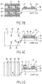
- This process comprises a first step ( figure 3A ) for supplying a first polyimide substrate in the form of a plastic film such as those marketed by DuPont Teijin Films to form the support sheet 15.
- the plate is freed from its impurities by cleaning in an ultrasonic bath with acetone and rinsed with ethanol or isopropanol in a manner known per se.
- the gaseous phase of the PECVD consists of a gaseous mixture of silicon tetrahydride (SiH 4), which is silane, nitrogen (N 2) and hydrogen (H 2), and is carried out at a temperature of less than 200 °, for example 165 ° vs.
- the desired silicon nitride layer is less than 100 nm thick, for example 50 nm thick.
- a third deposition step, on the ceramic layer 18, of the network or layer of line electrodes 20, 20 ' is then carried out.
- the deposition is carried out by electron beam lithography or by Joule evaporation, to create the line metal contacts on a thickness of the order of 300 nm.
- the contacts are then etched by wet etching.
- the sample is immersed in a hot aluminum bath (about 50 ° C) with an etchant such as phosphoric acid (H3PO4) for a specified time.
- H3PO4 phosphoric acid
- This determined time can be of the order of 2 to 3 minutes.
- the sample is then rinsed under distilled water and dried under a N2 gas stream.
- the metal contacts comprise, a first in-line electrode 20, a second in-line electrode 20 'parallel to the first and a first 21 and second 22 contact pads.
- the first contact pad 21 is substantially parallelepipedal and orthogonal to the electrodes being connected to the first electrode 20 and extends in the space between the pair 20, 20 'of electrodes.
- the second pad 22 of square shape.
- the intermediate layer 23 is formed in a fourth step ( Figure 3B and 3C ).
- the manufacturing method consists of a substep of depositing the piezoelectric layer 24 of semiconductors.
- the piezoelectric layer 24 completely covers the pads 21, 22 of the line electrodes and fills the space between the two electrode pads 21 and 22 of the same pair.
- the deposition is carried out by PECVD, for example by depositing a thickness of about 130 nm of microcrystalline silicon nitride doped with Arsenic (AsH4).
- Etching is done by a method known to those skilled in the art as reactive ion etching (RIE) using plasma sulfur hexafluoride (SF6).
- RIE reactive ion etching
- SF6 plasma sulfur hexafluoride
- the intermediate layer is thus formed by plasma deposition of doped silicon under an insulating layer.
- the second substep of the formation of this layer consists of depositing the layer of electrically insulating material.
- This layer has a maximum thickness of 300 nm.
- This layer will have holes 28 passing through the second pads 22 of the first layer of line electrode array.
- the insulating material is, for example, silicon oxide (SiO 2). It is deposited for example by spraying and is followed by photolithography. Etching is done by reactive ion etching RIE using SF6.
- a fifth step depositing the layer, said third layer, of column electrodes 30, 30 'for example 500 nm thick, aluminum by Joule effect evaporation, followed by a photo-lithography to create the second metal contacts 22 of columns in a network orthogonal to the network of lines.
- the network is arranged in such a way that the lines of a pair of column electrodes 30 pass in line with the first 21 and second 22 contact pads.
- One of the column electrodes 30 of the pair overhangs in order an insulating layer 27, a piezoelectric layer 24 and the first contact pad 21.
- the other is directly to the right of a piezoelectric layer 24 and the second contact pad 22.
- the previously obtained assembly undergoes thermal annealing at a low temperature (for example less than 200 ° C., for example 180 ° C.) for a determined time, for example 2 hours in an oven.
- a low temperature for example less than 200 ° C., for example 180 ° C.
- a determined time for example 2 hours in an oven.
- the figure 4 shows in perspective the sensor member 6 of the figure 1 . It comprises a support piece S in the form of a filamentary arch A, rigid, external support of the plate 14 on which it is fixed for example removably by self-adhesive points P distributed on the outer face of the support sheet 15 made of flexible plastic material, the plate 14.
- the support piece S comprises on one side a U-shaped part adapted to be placed on the side of the teeth and is closed on the other side by a stiffening bar B of the branches of the U which will come over the patient's palace.
- the rigid arch form, slightly spoon-shaped, for example, of the support piece is arranged to fit easily into the patient's mouth so that the plate 14 can be in contact, sandwiched between the teeth of the top and the below, by releasing precisely this contact surface.
- the hoop has a portion that is substantially horseshoe-shaped or "U” in plan view and comprises a central bar between the branches of the "U” which forms a convex portion, which can for example come abut against the Palatine arch of the patient, to ensure the good behavior of the whole.
- This comprises a measurement end itself, provided with a central portion C devoid of sensor and two peripheral portions H, symmetrical with respect to the transverse axis XX 'of the sensor member 6, inside. the arch and vis-à-vis the teeth, provided with said sensors 17.
- the plate also includes connecting pins 33, outside the support arch on the opposite side to the central portion C and to the handle by the dentist.
- connection pins 33 come into contact with pins (not shown) integral with a support plate R (in mixed lines) which make it possible to recover the measurements of the plate and to transmit them to the calculation means via the d-card. acquisition 9.
- the sensor plate 14 is reusable a predetermined number of times or disposable.
- each line electrode 20 is split by a parallel offset electrode 20 'allowing flexibility of geometry in the formation of in particular, the detector member allows the "U" formation of the plate.
- the two electrodes 20, 20 'thus form a pair of electrodes.
- Each line electrode (one per pair) and column is connected to a connection pin 33 known per se and mounted on the support member and forming a connection element.
- An electrical voltage is for example applied between a line pin 20 and a column pin 30.
- the intensity of the current is measured at one of the pins and is according to the law of ohm function of the electrical resistance on the path of the electrons.
- the electrical measurement can be connected to a geometrical datum because the electrical contact can be made between line and column only through the piezoelectric layer and through the through holes of the insulating layer.
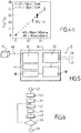
- ⁇ R is the variation of electrical resistance between the initial resistance and the final resistance
- R0 the initial electrical resistance
- FG the gauge factor (constant characteristic of the piezoelectric material)
- ⁇ epsilon
- the previously described model can relate to a layer of PEN sandwiched between two silicon nitride layers.
- the layers having for example and respectively 125 .mu.m, 550 nm and 250 nm thickness.
- Y f are Young's Modules of the Substrate (Y s ) ie 2.5GPa, and Silicon Nitride (Y f ) layers ie 270 GPa.
- the abscissa shows the epsilon stress in% and the ordinate the relative variation of the current.
- the four values obtained are given by varying the width (W) for the same length (L) or vice versa. This limitation makes it possible to obtain a measurement accuracy of the micrometric order.
- the device comprises acquisition means ( figure 5 ).
- acquisition means comprise an acquisition card 34 on which are mounted a module 35 for multiplexing / demultiplexing the information coming from lines 36 and columns 37.
- the card also comprises means 38 electrical signal adapters for supplying a 39/40 analog / digital converter to allow processing by the calculation means 10, and a module 41 for communicating the card with the computer. 12.
- Each pressure measurement comprises two resistivity measurements, the first said initial without pressure applied to measure and the second with the pressure to be measured applied to the object.
- the dentist (hand 7) engages via the computer 12, the beginning of the measurement.
- a first pass of the measurements of all the sensors is carried out and the result is introduced into a memory of the computer in the form for example of "Line 5 - column 27 - Initial - 28 ( M ⁇ ) Megohms ".
- a second step (43) the support piece provided with the plate 14 is introduced into the mouth of the patient 5 which closes its jaw 4.
- the plate 14 is sandwiched between the upper and lower teeth.
- the jaw then exerts and maintains a substantially constant pressure, which can be determined medium pressure easily by averaged measurement and calculation.
- the calculation means 10 then control (step 44) a second measurement of all or some pressure sensors.
- the calculation means 10 having internal characteristics of the detector member (in particular the thicknesses and the Young's moduli of the materials) previously introduced into the computer and having the differences in resistance between the initial positions and under pressure for a pair of coordinates (row / column) data, they determine the pressure applied to the plate for each pair of coordinates (step 45).
- the computation means For each coordinate of the space in the plane, the computation means then associate (step 46) a value of difference of resistance and therefore of pressure and establish the field of pressure intensities, thus realizing the mapping (step 47) of the forces occlusion of the patient.
- Each pressure intensity corresponds to an intensity of deformation and penetration of a tooth in the thickness of the detection plate.
- the measurements thus make it possible to determine the occlusal surface (coordinates) and the forces (intensity of the pressure).
- the second measurement of the pressure can be repeated (test 53), for example with a refresh rate greater than 100 hz so as to have a dynamic determination.
- the calculation means comprise timestamping means and record for each measurement the time spent with respect to a reference event (for example the engagement of the measurement).
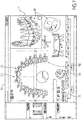
- the calculation means 10 furthermore comprise means arranged for dynamically displaying on a computer screen 50 the mapping 11 of the occlusal forces as well as possibly the shape 51 of the patient's dentition by integrating complementary data 52 (data on the jaw specific to a particular patient, history, dates, etc.).
- the data is then fused to the determined occlusal surface data to form a complete map of the patient's dentition 53 and the occlusal forces 54 that he experiences while eating.
- a classic menu 55 windows type (registered trademark) allows for example to move in different files without difficulty by simple click, synthetic representations for example in the form of camembert 56 can be displayed.
- the data acquired is also refreshed dynamically.
Landscapes
- Health & Medical Sciences (AREA)
- Life Sciences & Earth Sciences (AREA)
- Engineering & Computer Science (AREA)
- Biomedical Technology (AREA)
- Biophysics (AREA)
- Oral & Maxillofacial Surgery (AREA)
- Dentistry (AREA)
- Epidemiology (AREA)
- Animal Behavior & Ethology (AREA)
- General Health & Medical Sciences (AREA)
- Public Health (AREA)
- Veterinary Medicine (AREA)
- Physics & Mathematics (AREA)
- General Physics & Mathematics (AREA)
- Dental Tools And Instruments Or Auxiliary Dental Instruments (AREA)
Applications Claiming Priority (2)
| Application Number | Priority Date | Filing Date | Title |
|---|---|---|---|
| FR1361996A FR3013959B1 (fr) | 2013-12-03 | 2013-12-03 | Systeme de determination de la surface de contact et de la repartition des forces occlusales entre les dents d'une machoire de patient et procede correspondant. |
| PCT/FR2014/053155 WO2015082846A1 (fr) | 2013-12-03 | 2014-12-03 | Systeme de determination de la surface de contact et de la repartition des forces occlusales entre les dents d'une machoire de patient et procede correspondant. |
Publications (2)
| Publication Number | Publication Date |
|---|---|
| EP3076897A1 EP3076897A1 (fr) | 2016-10-12 |
| EP3076897B1 true EP3076897B1 (fr) | 2018-01-31 |
Family
ID=50424438
Family Applications (1)
| Application Number | Title | Priority Date | Filing Date |
|---|---|---|---|
| EP14821793.8A Not-in-force EP3076897B1 (fr) | 2013-12-03 | 2014-12-03 | Système de détermination de la surface de contact et de la répartition des forces occlusales entre les dents d'une machoire de patient et procédé correspondant |
Country Status (9)
| Country | Link |
|---|---|
| US (1) | US20160302901A1 (enExample) |
| EP (1) | EP3076897B1 (enExample) |
| JP (1) | JP2017501785A (enExample) |
| CA (1) | CA2932326A1 (enExample) |
| DK (1) | DK3076897T3 (enExample) |
| ES (1) | ES2667432T3 (enExample) |
| FR (1) | FR3013959B1 (enExample) |
| HU (1) | HUE038807T2 (enExample) |
| WO (1) | WO2015082846A1 (enExample) |
Families Citing this family (5)
| Publication number | Priority date | Publication date | Assignee | Title |
|---|---|---|---|---|
| US10201406B2 (en) | 2015-08-18 | 2019-02-12 | International Business Machines Corporation | Device and method for facilitating tooth contact adjustment using a pressure device |
| EP3682847A4 (en) * | 2017-09-14 | 2021-06-02 | GC Corporation | OCCLUSAL PRESSURE ANALYSIS DEVICE, OCCLUSAL PRESSURE ANALYSIS PROGRAM, AND OCCLUSAL PRESSURE ANALYSIS METHOD |
| US11020047B2 (en) * | 2018-06-01 | 2021-06-01 | Otis Dental, LLC | Computerized sensor system and mouthguard device |
| WO2021014860A1 (ja) * | 2019-07-22 | 2021-01-28 | 株式会社村田製作所 | 口腔センサ |
| PL74291Y1 (pl) * | 2024-05-29 | 2026-03-09 | Akademia Wychowania Fizycznego Im Eugeniusza Piaseckiego W Poznaniu | Urządzenie do pomiaru siły zacisku kości szczęki i kości żuchwy |
Family Cites Families (14)
| Publication number | Priority date | Publication date | Assignee | Title |
|---|---|---|---|---|
| JPS56142430A (en) * | 1980-03-24 | 1981-11-06 | Morita Mfg Co Ltd | Biting pressure sensor |
| JPS5848175B2 (ja) * | 1980-05-02 | 1983-10-27 | 株式会社 モリタ製作所 | 全顎の咬合圧画像表示装置 |
| JPS6134981A (ja) * | 1984-07-26 | 1986-02-19 | Sumitomo Electric Ind Ltd | 二次元歪センサ |
| US4856993A (en) * | 1985-03-29 | 1989-08-15 | Tekscan, Inc. | Pressure and contact sensor system for measuring dental occlusion |
| US4734034A (en) * | 1985-03-29 | 1988-03-29 | Sentek, Incorporated | Contact sensor for measuring dental occlusion |
| US5086652A (en) * | 1991-02-25 | 1992-02-11 | Fel-Pro Incorporated | Multiple pad contact sensor and method for measuring contact forces at a plurality of separate locations |
| US5760530A (en) * | 1992-12-22 | 1998-06-02 | The United States Of America As Represented By The Secretary Of The Air Force | Piezoelectric tactile sensor |
| US5756904A (en) * | 1996-08-30 | 1998-05-26 | Tekscan, Inc. | Pressure responsive sensor having controlled scanning speed |
| US6441395B1 (en) * | 1998-02-02 | 2002-08-27 | Uniax Corporation | Column-row addressable electric microswitch arrays and sensor matrices employing them |
| US8327721B2 (en) * | 2009-10-26 | 2012-12-11 | Hewlett-Packard Development Company, L.P. | Sensor fabric for shape perception |
| JP5198608B2 (ja) * | 2010-03-18 | 2013-05-15 | 韓国標準科学研究院 | 半導体ストレインゲージを用いたフレキシブルな力または圧力センサアレイ、そのフレキシブルな力または圧力センサアレイの製造方法、及びそのフレキシブルな力または圧力センサアレイを用いた力または圧力測定方法 |
| JP2012065938A (ja) * | 2010-09-27 | 2012-04-05 | Gc Corp | 咬合圧測定器、及び咬合圧測定装置 |
| US20120162122A1 (en) * | 2010-12-27 | 2012-06-28 | 3M Innovative Properties Company | Force sensitive device with force sensitive resistors |
| JP4900629B1 (ja) * | 2011-08-01 | 2012-03-21 | 秀士 片瀬 | 上下顎関係採得セット |
-
2013
- 2013-12-03 FR FR1361996A patent/FR3013959B1/fr not_active Expired - Fee Related
-
2014
- 2014-12-03 JP JP2016536808A patent/JP2017501785A/ja active Pending
- 2014-12-03 EP EP14821793.8A patent/EP3076897B1/fr not_active Not-in-force
- 2014-12-03 DK DK14821793.8T patent/DK3076897T3/en active
- 2014-12-03 CA CA2932326A patent/CA2932326A1/fr not_active Abandoned
- 2014-12-03 US US15/101,245 patent/US20160302901A1/en not_active Abandoned
- 2014-12-03 ES ES14821793.8T patent/ES2667432T3/es active Active
- 2014-12-03 WO PCT/FR2014/053155 patent/WO2015082846A1/fr not_active Ceased
- 2014-12-03 HU HUE14821793A patent/HUE038807T2/hu unknown
Also Published As
| Publication number | Publication date |
|---|---|
| FR3013959A1 (fr) | 2015-06-05 |
| WO2015082846A1 (fr) | 2015-06-11 |
| DK3076897T3 (en) | 2018-05-22 |
| US20160302901A1 (en) | 2016-10-20 |
| ES2667432T3 (es) | 2018-05-10 |
| CA2932326A1 (fr) | 2015-06-11 |
| EP3076897A1 (fr) | 2016-10-12 |
| HUE038807T2 (hu) | 2018-11-28 |
| JP2017501785A (ja) | 2017-01-19 |
| FR3013959B1 (fr) | 2016-01-08 |
Similar Documents
| Publication | Publication Date | Title |
|---|---|---|
| EP2309559B1 (fr) | Structure d'actionnement piézoélectrique comportant une jauge de contrainte piézorésistive intégrée et son procédé de réalisation | |
| WO2015082846A1 (fr) | Systeme de determination de la surface de contact et de la repartition des forces occlusales entre les dents d'une machoire de patient et procede correspondant. | |
| EP2396636B1 (fr) | Capteur de force de contact | |
| EP1056985B1 (fr) | Capteur d'extensiometrie destine a mesurer des deformations a calage mecanique de premiere pose et calibrage automatique en fonction de ce calage | |
| FR2919486A1 (fr) | Capteur de pression auto-etalonnable. | |
| FR2852102A1 (fr) | Capteur de pression a semiconducteur ayant une membrane | |
| FR2983955A1 (fr) | Capteur de pression pour fluide | |
| WO2021170883A1 (fr) | Surface tactile fonctionnalisée par un capteur de force et un capteur de proximité combinés | |
| FR2967774A1 (fr) | Capteur de pression miniaturise | |
| FR3053116A1 (fr) | Capteur et ecran tactile a compensation environnementale, notamment en temperature | |
| FR2995995A1 (fr) | Capteur de pression a base de nanojauges couplees a un resonateur | |
| EP2320469A1 (fr) | Procédé de réalisation d'un circuit courbe | |
| FR2942660A1 (fr) | Dispositif capteur a base de nanofils | |
| EP4449054B1 (fr) | Microcapteur à électrodes interdigitées | |
| FR3117592A1 (fr) | Capteur de force | |
| EP3076896A1 (fr) | Systeme de determination de la forme au moins partielle d'un objet tridimentionnel et procede correspondant | |
| EP0053059B1 (fr) | Dispositif de mesure comprenant une jauge de contrainte avec un support en verre mince | |
| EP0244324B1 (fr) | Capteur de force à jauges résistives | |
| EP2862000B1 (fr) | Capteur de champ magnetique a force de laplace | |
| EP2157402B1 (fr) | Dispositif de mesure d'alignement de structures accolees | |
| FR3052916A1 (fr) | Actionneur electromecanique | |
| BE879309A (fr) | Dispositif mesureur de pression utilisant un extensometre a resistors | |
| FR2654210A1 (fr) | Dispositif de mesure pour la determination d'une grandeur physique. | |
| FR2947628A1 (fr) | Procede de fabrication d'une jauge de deformation en circuit integre | |
| CA2321134A1 (fr) | Capteur d'extensiometrie destine a mesurer des deformations a calage mecanique de premiere pose et calibrage automatique en fonction de ce calage |
Legal Events
| Date | Code | Title | Description |
|---|---|---|---|
| PUAI | Public reference made under article 153(3) epc to a published international application that has entered the european phase |
Free format text: ORIGINAL CODE: 0009012 |
|
| 17P | Request for examination filed |
Effective date: 20160602 |
|
| AK | Designated contracting states |
Kind code of ref document: A1 Designated state(s): AL AT BE BG CH CY CZ DE DK EE ES FI FR GB GR HR HU IE IS IT LI LT LU LV MC MK MT NL NO PL PT RO RS SE SI SK SM TR |
|
| AX | Request for extension of the european patent |
Extension state: BA ME |
|
| DAX | Request for extension of the european patent (deleted) | ||
| GRAP | Despatch of communication of intention to grant a patent |
Free format text: ORIGINAL CODE: EPIDOSNIGR1 |
|
| STAA | Information on the status of an ep patent application or granted ep patent |
Free format text: STATUS: GRANT OF PATENT IS INTENDED |
|
| INTG | Intention to grant announced |
Effective date: 20170727 |
|
| GRAS | Grant fee paid |
Free format text: ORIGINAL CODE: EPIDOSNIGR3 |
|
| GRAA | (expected) grant |
Free format text: ORIGINAL CODE: 0009210 |
|
| STAA | Information on the status of an ep patent application or granted ep patent |
Free format text: STATUS: THE PATENT HAS BEEN GRANTED |
|
| AK | Designated contracting states |
Kind code of ref document: B1 Designated state(s): AL AT BE BG CH CY CZ DE DK EE ES FI FR GB GR HR HU IE IS IT LI LT LU LV MC MK MT NL NO PL PT RO RS SE SI SK SM TR |
|
| REG | Reference to a national code |
Ref country code: GB Ref legal event code: FG4D Free format text: NOT ENGLISH Ref country code: CH Ref legal event code: EP |
|
| REG | Reference to a national code |
Ref country code: AT Ref legal event code: REF Ref document number: 966654 Country of ref document: AT Kind code of ref document: T Effective date: 20180215 |
|
| REG | Reference to a national code |
Ref country code: IE Ref legal event code: FG4D Free format text: LANGUAGE OF EP DOCUMENT: FRENCH |
|
| REG | Reference to a national code |
Ref country code: DE Ref legal event code: R096 Ref document number: 602014020593 Country of ref document: DE |
|
| REG | Reference to a national code |
Ref country code: NL Ref legal event code: FP |
|
| REG | Reference to a national code |
Ref country code: ES Ref legal event code: FG2A Ref document number: 2667432 Country of ref document: ES Kind code of ref document: T3 Effective date: 20180510 |
|
| REG | Reference to a national code |
Ref country code: SE Ref legal event code: TRGR |
|
| REG | Reference to a national code |
Ref country code: DK Ref legal event code: T3 Effective date: 20180517 |
|
| REG | Reference to a national code |
Ref country code: CH Ref legal event code: NV Representative=s name: CRONIN INTELLECTUAL PROPERTY, CH |
|
| REG | Reference to a national code |
Ref country code: LT Ref legal event code: MG4D |
|
| PG25 | Lapsed in a contracting state [announced via postgrant information from national office to epo] |
Ref country code: LT Free format text: LAPSE BECAUSE OF FAILURE TO SUBMIT A TRANSLATION OF THE DESCRIPTION OR TO PAY THE FEE WITHIN THE PRESCRIBED TIME-LIMIT Effective date: 20180131 Ref country code: NO Free format text: LAPSE BECAUSE OF FAILURE TO SUBMIT A TRANSLATION OF THE DESCRIPTION OR TO PAY THE FEE WITHIN THE PRESCRIBED TIME-LIMIT Effective date: 20180430 Ref country code: HR Free format text: LAPSE BECAUSE OF FAILURE TO SUBMIT A TRANSLATION OF THE DESCRIPTION OR TO PAY THE FEE WITHIN THE PRESCRIBED TIME-LIMIT Effective date: 20180131 |
|
| PG25 | Lapsed in a contracting state [announced via postgrant information from national office to epo] |
Ref country code: GR Free format text: LAPSE BECAUSE OF FAILURE TO SUBMIT A TRANSLATION OF THE DESCRIPTION OR TO PAY THE FEE WITHIN THE PRESCRIBED TIME-LIMIT Effective date: 20180501 Ref country code: RS Free format text: LAPSE BECAUSE OF FAILURE TO SUBMIT A TRANSLATION OF THE DESCRIPTION OR TO PAY THE FEE WITHIN THE PRESCRIBED TIME-LIMIT Effective date: 20180131 Ref country code: PL Free format text: LAPSE BECAUSE OF FAILURE TO SUBMIT A TRANSLATION OF THE DESCRIPTION OR TO PAY THE FEE WITHIN THE PRESCRIBED TIME-LIMIT Effective date: 20180131 Ref country code: BG Free format text: LAPSE BECAUSE OF FAILURE TO SUBMIT A TRANSLATION OF THE DESCRIPTION OR TO PAY THE FEE WITHIN THE PRESCRIBED TIME-LIMIT Effective date: 20180430 Ref country code: IS Free format text: LAPSE BECAUSE OF FAILURE TO SUBMIT A TRANSLATION OF THE DESCRIPTION OR TO PAY THE FEE WITHIN THE PRESCRIBED TIME-LIMIT Effective date: 20180531 Ref country code: LV Free format text: LAPSE BECAUSE OF FAILURE TO SUBMIT A TRANSLATION OF THE DESCRIPTION OR TO PAY THE FEE WITHIN THE PRESCRIBED TIME-LIMIT Effective date: 20180131 |
|
| PG25 | Lapsed in a contracting state [announced via postgrant information from national office to epo] |
Ref country code: MT Free format text: LAPSE BECAUSE OF FAILURE TO SUBMIT A TRANSLATION OF THE DESCRIPTION OR TO PAY THE FEE WITHIN THE PRESCRIBED TIME-LIMIT Effective date: 20180131 |
|
| PG25 | Lapsed in a contracting state [announced via postgrant information from national office to epo] |
Ref country code: AL Free format text: LAPSE BECAUSE OF FAILURE TO SUBMIT A TRANSLATION OF THE DESCRIPTION OR TO PAY THE FEE WITHIN THE PRESCRIBED TIME-LIMIT Effective date: 20180131 Ref country code: EE Free format text: LAPSE BECAUSE OF FAILURE TO SUBMIT A TRANSLATION OF THE DESCRIPTION OR TO PAY THE FEE WITHIN THE PRESCRIBED TIME-LIMIT Effective date: 20180131 |
|
| REG | Reference to a national code |
Ref country code: DE Ref legal event code: R097 Ref document number: 602014020593 Country of ref document: DE |
|
| REG | Reference to a national code |
Ref country code: HU Ref legal event code: AG4A Ref document number: E038807 Country of ref document: HU |
|
| PG25 | Lapsed in a contracting state [announced via postgrant information from national office to epo] |
Ref country code: SM Free format text: LAPSE BECAUSE OF FAILURE TO SUBMIT A TRANSLATION OF THE DESCRIPTION OR TO PAY THE FEE WITHIN THE PRESCRIBED TIME-LIMIT Effective date: 20180131 Ref country code: CZ Free format text: LAPSE BECAUSE OF FAILURE TO SUBMIT A TRANSLATION OF THE DESCRIPTION OR TO PAY THE FEE WITHIN THE PRESCRIBED TIME-LIMIT Effective date: 20180131 Ref country code: SK Free format text: LAPSE BECAUSE OF FAILURE TO SUBMIT A TRANSLATION OF THE DESCRIPTION OR TO PAY THE FEE WITHIN THE PRESCRIBED TIME-LIMIT Effective date: 20180131 |
|
| PLBE | No opposition filed within time limit |
Free format text: ORIGINAL CODE: 0009261 |
|
| STAA | Information on the status of an ep patent application or granted ep patent |
Free format text: STATUS: NO OPPOSITION FILED WITHIN TIME LIMIT |
|
| PGFP | Annual fee paid to national office [announced via postgrant information from national office to epo] |
Ref country code: NL Payment date: 20181114 Year of fee payment: 5 |
|
| 26N | No opposition filed |
Effective date: 20181102 |
|
| PGFP | Annual fee paid to national office [announced via postgrant information from national office to epo] |
Ref country code: HU Payment date: 20181126 Year of fee payment: 5 Ref country code: IE Payment date: 20181127 Year of fee payment: 5 Ref country code: SE Payment date: 20181213 Year of fee payment: 5 Ref country code: FI Payment date: 20181220 Year of fee payment: 5 |
|
| PG25 | Lapsed in a contracting state [announced via postgrant information from national office to epo] |
Ref country code: SI Free format text: LAPSE BECAUSE OF FAILURE TO SUBMIT A TRANSLATION OF THE DESCRIPTION OR TO PAY THE FEE WITHIN THE PRESCRIBED TIME-LIMIT Effective date: 20180131 |
|
| PGFP | Annual fee paid to national office [announced via postgrant information from national office to epo] |
Ref country code: BE Payment date: 20181220 Year of fee payment: 5 Ref country code: CH Payment date: 20181219 Year of fee payment: 5 Ref country code: GB Payment date: 20181218 Year of fee payment: 5 |
|
| PGFP | Annual fee paid to national office [announced via postgrant information from national office to epo] |
Ref country code: ES Payment date: 20190125 Year of fee payment: 5 |
|
| PG25 | Lapsed in a contracting state [announced via postgrant information from national office to epo] |
Ref country code: MC Free format text: LAPSE BECAUSE OF FAILURE TO SUBMIT A TRANSLATION OF THE DESCRIPTION OR TO PAY THE FEE WITHIN THE PRESCRIBED TIME-LIMIT Effective date: 20180131 Ref country code: LU Free format text: LAPSE BECAUSE OF NON-PAYMENT OF DUE FEES Effective date: 20181203 |
|
| PG25 | Lapsed in a contracting state [announced via postgrant information from national office to epo] |
Ref country code: TR Free format text: LAPSE BECAUSE OF FAILURE TO SUBMIT A TRANSLATION OF THE DESCRIPTION OR TO PAY THE FEE WITHIN THE PRESCRIBED TIME-LIMIT Effective date: 20180131 |
|
| PG25 | Lapsed in a contracting state [announced via postgrant information from national office to epo] |
Ref country code: PT Free format text: LAPSE BECAUSE OF FAILURE TO SUBMIT A TRANSLATION OF THE DESCRIPTION OR TO PAY THE FEE WITHIN THE PRESCRIBED TIME-LIMIT Effective date: 20180131 |
|
| PG25 | Lapsed in a contracting state [announced via postgrant information from national office to epo] |
Ref country code: MK Free format text: LAPSE BECAUSE OF NON-PAYMENT OF DUE FEES Effective date: 20180131 Ref country code: CY Free format text: LAPSE BECAUSE OF FAILURE TO SUBMIT A TRANSLATION OF THE DESCRIPTION OR TO PAY THE FEE WITHIN THE PRESCRIBED TIME-LIMIT Effective date: 20180131 Ref country code: RO Free format text: LAPSE BECAUSE OF FAILURE TO SUBMIT A TRANSLATION OF THE DESCRIPTION OR TO PAY THE FEE WITHIN THE PRESCRIBED TIME-LIMIT Effective date: 20180131 |
|
| REG | Reference to a national code |
Ref country code: FI Ref legal event code: MAE |
|
| REG | Reference to a national code |
Ref country code: DK Ref legal event code: EBP Effective date: 20191231 |
|
| REG | Reference to a national code |
Ref country code: SE Ref legal event code: EUG |
|
| PG25 | Lapsed in a contracting state [announced via postgrant information from national office to epo] |
Ref country code: FI Free format text: LAPSE BECAUSE OF NON-PAYMENT OF DUE FEES Effective date: 20191203 |
|
| REG | Reference to a national code |
Ref country code: CH Ref legal event code: PL |
|
| REG | Reference to a national code |
Ref country code: NL Ref legal event code: MM Effective date: 20200101 |
|
| REG | Reference to a national code |
Ref country code: BE Ref legal event code: MM Effective date: 20191231 |
|
| GBPC | Gb: european patent ceased through non-payment of renewal fee |
Effective date: 20191203 |
|
| PG25 | Lapsed in a contracting state [announced via postgrant information from national office to epo] |
Ref country code: NL Free format text: LAPSE BECAUSE OF NON-PAYMENT OF DUE FEES Effective date: 20200101 |
|
| PG25 | Lapsed in a contracting state [announced via postgrant information from national office to epo] |
Ref country code: SE Free format text: LAPSE BECAUSE OF NON-PAYMENT OF DUE FEES Effective date: 20191204 Ref country code: GB Free format text: LAPSE BECAUSE OF NON-PAYMENT OF DUE FEES Effective date: 20191203 Ref country code: IT Free format text: LAPSE BECAUSE OF NON-PAYMENT OF DUE FEES Effective date: 20191203 Ref country code: IE Free format text: LAPSE BECAUSE OF NON-PAYMENT OF DUE FEES Effective date: 20191203 |
|
| PG25 | Lapsed in a contracting state [announced via postgrant information from national office to epo] |
Ref country code: LI Free format text: LAPSE BECAUSE OF NON-PAYMENT OF DUE FEES Effective date: 20191231 Ref country code: CH Free format text: LAPSE BECAUSE OF NON-PAYMENT OF DUE FEES Effective date: 20191231 Ref country code: HU Free format text: LAPSE BECAUSE OF NON-PAYMENT OF DUE FEES Effective date: 20191204 Ref country code: BE Free format text: LAPSE BECAUSE OF NON-PAYMENT OF DUE FEES Effective date: 20191231 |
|
| PG25 | Lapsed in a contracting state [announced via postgrant information from national office to epo] |
Ref country code: DK Free format text: LAPSE BECAUSE OF NON-PAYMENT OF DUE FEES Effective date: 20191231 |
|
| REG | Reference to a national code |
Ref country code: AT Ref legal event code: MM01 Ref document number: 966654 Country of ref document: AT Kind code of ref document: T Effective date: 20191203 |
|
| REG | Reference to a national code |
Ref country code: ES Ref legal event code: FD2A Effective date: 20210528 |
|
| PG25 | Lapsed in a contracting state [announced via postgrant information from national office to epo] |
Ref country code: AT Free format text: LAPSE BECAUSE OF NON-PAYMENT OF DUE FEES Effective date: 20191203 |
|
| REG | Reference to a national code |
Ref country code: AT Ref legal event code: UEP Ref document number: 966654 Country of ref document: AT Kind code of ref document: T Effective date: 20180131 |
|
| PG25 | Lapsed in a contracting state [announced via postgrant information from national office to epo] |
Ref country code: ES Free format text: LAPSE BECAUSE OF NON-PAYMENT OF DUE FEES Effective date: 20191204 |
|
| PGFP | Annual fee paid to national office [announced via postgrant information from national office to epo] |
Ref country code: DE Payment date: 20220222 Year of fee payment: 8 |
|
| PGFP | Annual fee paid to national office [announced via postgrant information from national office to epo] |
Ref country code: FR Payment date: 20220214 Year of fee payment: 8 |
|
| REG | Reference to a national code |
Ref country code: DE Ref legal event code: R119 Ref document number: 602014020593 Country of ref document: DE |
|
| PG25 | Lapsed in a contracting state [announced via postgrant information from national office to epo] |
Ref country code: DE Free format text: LAPSE BECAUSE OF NON-PAYMENT OF DUE FEES Effective date: 20230701 |
|
| PG25 | Lapsed in a contracting state [announced via postgrant information from national office to epo] |
Ref country code: FR Free format text: LAPSE BECAUSE OF NON-PAYMENT OF DUE FEES Effective date: 20221231 |