EP3076684A1 - Communicaton device, receiving device, and communication system for transmitting information in daisy chain network - Google Patents
Communicaton device, receiving device, and communication system for transmitting information in daisy chain network Download PDFInfo
- Publication number
- EP3076684A1 EP3076684A1 EP16159426.2A EP16159426A EP3076684A1 EP 3076684 A1 EP3076684 A1 EP 3076684A1 EP 16159426 A EP16159426 A EP 16159426A EP 3076684 A1 EP3076684 A1 EP 3076684A1
- Authority
- EP
- European Patent Office
- Prior art keywords
- signal
- transmission rate
- communication device
- daisy chain
- chain connection
- Prior art date
- Legal status (The legal status is an assumption and is not a legal conclusion. Google has not performed a legal analysis and makes no representation as to the accuracy of the status listed.)
- Granted
Links
Images

Classifications
-
- H—ELECTRICITY
- H04—ELECTRIC COMMUNICATION TECHNIQUE
- H04Q—SELECTING
- H04Q9/00—Arrangements in telecontrol or telemetry systems for selectively calling a substation from a main station, in which substation desired apparatus is selected for applying a control signal thereto or for obtaining measured values therefrom
-
- G—PHYSICS
- G06—COMPUTING OR CALCULATING; COUNTING
- G06F—ELECTRIC DIGITAL DATA PROCESSING
- G06F13/00—Interconnection of, or transfer of information or other signals between, memories, input/output devices or central processing units
- G06F13/38—Information transfer, e.g. on bus
- G06F13/42—Bus transfer protocol, e.g. handshake; Synchronisation
- G06F13/4247—Bus transfer protocol, e.g. handshake; Synchronisation on a daisy chain bus
-
- G—PHYSICS
- G08—SIGNALLING
- G08C—TRANSMISSION SYSTEMS FOR MEASURED VALUES, CONTROL OR SIMILAR SIGNALS
- G08C23/00—Non-electrical signal transmission systems, e.g. optical systems
- G08C23/06—Non-electrical signal transmission systems, e.g. optical systems through light guides, e.g. optical fibres
-
- G—PHYSICS
- G05—CONTROLLING; REGULATING
- G05B—CONTROL OR REGULATING SYSTEMS IN GENERAL; FUNCTIONAL ELEMENTS OF SUCH SYSTEMS; MONITORING OR TESTING ARRANGEMENTS FOR SUCH SYSTEMS OR ELEMENTS
- G05B2219/00—Program-control systems
- G05B2219/30—Nc systems
- G05B2219/33—Director till display
- G05B2219/33226—Daisy chain
-
- G—PHYSICS
- G06—COMPUTING OR CALCULATING; COUNTING
- G06F—ELECTRIC DIGITAL DATA PROCESSING
- G06F13/00—Interconnection of, or transfer of information or other signals between, memories, input/output devices or central processing units
- G06F13/38—Information transfer, e.g. on bus
- G06F13/42—Bus transfer protocol, e.g. handshake; Synchronisation
- G06F13/4247—Bus transfer protocol, e.g. handshake; Synchronisation on a daisy chain bus
- G06F13/4252—Bus transfer protocol, e.g. handshake; Synchronisation on a daisy chain bus using a handshaking protocol
-
- H—ELECTRICITY
- H01—ELECTRIC ELEMENTS
- H01M—PROCESSES OR MEANS, e.g. BATTERIES, FOR THE DIRECT CONVERSION OF CHEMICAL ENERGY INTO ELECTRICAL ENERGY
- H01M10/00—Secondary cells; Manufacture thereof
- H01M10/42—Methods or arrangements for servicing or maintenance of secondary cells or secondary half-cells
- H01M10/425—Structural combination with electronic components, e.g. electronic circuits integrated to the outside of the casing
- H01M2010/4271—Battery management systems including electronic circuits, e.g. control of current or voltage to keep battery in healthy state, cell balancing
-
- H—ELECTRICITY
- H01—ELECTRIC ELEMENTS
- H01M—PROCESSES OR MEANS, e.g. BATTERIES, FOR THE DIRECT CONVERSION OF CHEMICAL ENERGY INTO ELECTRICAL ENERGY
- H01M10/00—Secondary cells; Manufacture thereof
- H01M10/42—Methods or arrangements for servicing or maintenance of secondary cells or secondary half-cells
- H01M10/425—Structural combination with electronic components, e.g. electronic circuits integrated to the outside of the casing
- H01M2010/4278—Systems for data transfer from batteries, e.g. transfer of battery parameters to a controller, data transferred between battery controller and main controller
-
- H—ELECTRICITY
- H04—ELECTRIC COMMUNICATION TECHNIQUE
- H04Q—SELECTING
- H04Q2209/00—Arrangements in telecontrol or telemetry systems
- H04Q2209/30—Arrangements in telecontrol or telemetry systems using a wired architecture
-
- Y—GENERAL TAGGING OF NEW TECHNOLOGICAL DEVELOPMENTS; GENERAL TAGGING OF CROSS-SECTIONAL TECHNOLOGIES SPANNING OVER SEVERAL SECTIONS OF THE IPC; TECHNICAL SUBJECTS COVERED BY FORMER USPC CROSS-REFERENCE ART COLLECTIONS [XRACs] AND DIGESTS
- Y02—TECHNOLOGIES OR APPLICATIONS FOR MITIGATION OR ADAPTATION AGAINST CLIMATE CHANGE
- Y02D—CLIMATE CHANGE MITIGATION TECHNOLOGIES IN INFORMATION AND COMMUNICATION TECHNOLOGIES [ICT], I.E. INFORMATION AND COMMUNICATION TECHNOLOGIES AIMING AT THE REDUCTION OF THEIR OWN ENERGY USE
- Y02D10/00—Energy efficient computing, e.g. low power processors, power management or thermal management
-
- Y—GENERAL TAGGING OF NEW TECHNOLOGICAL DEVELOPMENTS; GENERAL TAGGING OF CROSS-SECTIONAL TECHNOLOGIES SPANNING OVER SEVERAL SECTIONS OF THE IPC; TECHNICAL SUBJECTS COVERED BY FORMER USPC CROSS-REFERENCE ART COLLECTIONS [XRACs] AND DIGESTS
- Y02—TECHNOLOGIES OR APPLICATIONS FOR MITIGATION OR ADAPTATION AGAINST CLIMATE CHANGE
- Y02E—REDUCTION OF GREENHOUSE GAS [GHG] EMISSIONS, RELATED TO ENERGY GENERATION, TRANSMISSION OR DISTRIBUTION
- Y02E60/00—Enabling technologies; Technologies with a potential or indirect contribution to GHG emissions mitigation
- Y02E60/10—Energy storage using batteries
Definitions
- the disclosure relates to communication technology, and particularly to a communication device, a receiving device, and a communication system for transmitting information in a daisy chain network.
- a communication interface is provided in each of the battery cells.
- a plurality of communication interfaces is serially connected, and each of the communication interfaces transfers the voltage values (refer to WO 11/043311 A , for example).
- a daisy chain connection As a connection mode for transmitting voltage values of a plurality of battery cells to a microcomputer, there is a daisy chain connection.
- a daisy chain connection a plurality of communication interfaces is connected in an annular pattern like one ring.
- a daisy chain connection starting from a management device returns to the management device as an ending point via a plurality of communication interfaces. Consequently, in a communication interface located closer to the ending point, there is an increasing amount of information received from other communication interface and to be transferred, and a transfer amount is larger than that in a communication interface located closer to the starting point. Accordingly, power consumption in a communication interface located closer to the ending point is larger than that in a communication interface located closer to the starting point.
- the present invention has been made in view of the situation described above, and an object of the present invention is to provide a technique with which power consumption in a daisy chain connection is leveled.
- a communication device in an aspect of the present invention is included in a daisy chain connection, and includes a receiver, a transmitter, and an acceptor.
- the receiver receives a first signal from a preceding device in the daisy chain connection
- the transmitter transmits the first signal received in the receiver to a succeeding device in the daisy chain connection
- the acceptor accepts a second signal starting from the communication device.
- the transmitter transmits the second signal to the succeeding device at a transmission rate higher than that of the first signal.
- the device includes a receiver and a processor.
- the receiver receives a signal from each of a plurality of communication devices included in a daisy chain connection, for which signal a plurality of kinds of transmission rates is used.
- the processor processes the signal received in the receiver.
- a reference signal for identifying a transmission rate which signal has a common value irrespective of the transmission rate, is included in the signal received in the receiver.
- the receiver receives the signal at each of the plurality of kinds of transmission rates, and selects a transmission rate at which the reference signal for identifying a transmission rate has been detected.
- Still another aspect of the present invention is a communication system.
- the communication system includes a management device, and a plurality of communication devices daisy-chained from the management device.
- Each of the plurality of communication devices transfers a signal received from a preceding device in the daisy chain connection to a succeeding device in the daisy chain connection, and transmits, to the succeeding device, a signal starting from the communication device at a transmission rate higher than that used for the transfer.
- An embodiment of the present invention relates to a communication system in which communication devices provided in a plurality of battery packs, respectively, are daisy-chained.
- a communication device transmits a packet signal including predetermined information to a succeeding communication device.
- the succeeding communication device transmits a new packet signal including predetermined information to a communication device further succeeding the succeeding communication device, and transfers the packet signal received from the preceding communication device to the communication device further succeeding the succeeding communication device.
- each communication device performs, in addition to transmission of a new packet signal, transfer of a packet signal. Accordingly, a communication time required for transmission of a packet signal is longer in a communication device located closer to the ending point of the daisy chain connection, than in a communication device located closer to the starting point thereof.
- a remaining battery power varies among battery packs depending on a difference in power consumption.
- a remaining battery power in each battery pack is preferably leveled among the battery packs, and it is not preferable that the remaining battery power in each battery pack vary among the battery packs as a result of communication.
- the communication device uses a transmission rate for transferring a packet signal from a communication device located closer to an ending point of a daisy chain connection, which transmission rate is higher than a transmission rate for transferring a packet signal from a communication device located closer to a starting point thereof.
- a communication device located closer to the starting point (hereinafter referred to as "first communication device") transmits a packet signal at a transmission rate of 9600 bps, and other communication devices in the daisy chain connection transfer the packet signal at a transmission rate of 9600 bps.
- a communication device located closer to the ending point than the first communication device transmits a packet signal at a transmission rate of 19200 bps, which is higher than 9600 bps.
- the second communication device transfers the packet signal from the first communication device at a transmission rate of 9600 bps, as described above.
- the power distribution system 100 includes a storage battery system 10, a DC/DC converter 12, a bidirectional power conditioner 14, a load 16, and a commercial power supply 18.
- the storage battery system 10 includes a storage battery management unit 20, a storage battery unit 22, and a switch (SW) 24.
- the commercial power supply 18 is an AC power supply and power is supplied from a power company.
- the storage battery system 10 includes the storage battery unit 22 which includes a plurality of battery packs not illustrated. Here, for the sake of clearer description, one storage battery unit 22 is provided. However, a plurality of the storage battery units 22 may be provided.
- the SW 24 is provided between the storage battery unit 22 and the DC/DC converter 12, and connects and disconnects a conductive path between the storage battery unit 22 and the DC/DC converter 12.
- the storage battery management unit 20 manages each battery pack included in the storage battery unit 22, and also manages an operation of the SW 24. The management of the storage battery unit 22 by the storage battery management unit 20 will be described later.
- the DC/DC converter 12 is disposed in a conductive path between the SW 24 and the bidirectional power conditioner 14, steps up or steps down the DCpower converted by the bidirectional power conditioner 14, and causes the storage battery system 10 to charge or discharge power.
- the bidirectional power conditioner 14 includes a bidirectional inverter not illustrated.
- the inverter converts, to AC power, the DC power from the DC/DC converter 12, which DC power is discharged by the storage battery system 10, and outputs the AC power to the load 16.
- the inverter converts the AC power from the commercial power supply 18 to DC power, and outputs the DC power to the DC/DC converter 12.
- the load 16 operates when AC power is supplied thereto from the commercial power supply 18 or the bidirectional power conditioner 14.
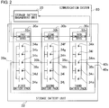
- FIG. 2 illustrates a connection between the storage battery unit 22 and the storage battery management unit 20.
- the storage battery unit 22 includes a first battery pack 30a, a second battery pack 30b, and a third battery pack 30c, which are collectively referred to as a battery pack 30, as well as a first terminal 40a and a second terminal 40b, which are collectively referred to as a terminal 40.
- the first battery pack 30a includes a first communication device 32a, a first storage battery 34a, a second storage battery 34b, a third storage battery 34c, a fourth storage battery 34d, a fifth storage battery 34e, a first positive electrode terminal 36a, and a first negative electrode terminal 38a.
- the second battery pack 30b includes a second communication device 32b, a sixth storage battery 34f, a seventh storage battery 34g, an eighth storage battery 34h, a ninth storage battery 34i, a tenth storage battery 34j , a second positive electrode terminal 36b, and a second negative electrode terminal 38b.
- the third battery pack 30c includes a third communication device 32c, an eleventh storage battery 34k, a twelfth storage battery 341, a thirteenth storage battery 34m, a fourteenth storage battery 34n, a fifteenth storage battery 34o, a third positive electrode terminal 36c, and a third negative electrode terminal 38c.
- the first communication device 32a, the second communication device 32b, and the third communication device 32c are collectively referred to as a communication device 32.
- the first storage battery 34a to the fifteenth storage battery 34o are collectively referred to as a storage battery 34.
- the first positive electrode terminal 36a, the second positive electrode terminal 36b, and the third positive electrode terminal 36c are collectively referred to as a positive electrode terminal 36.
- the first negative electrode terminal 38a, the second negative electrode terminal 38b, and the third negative electrode terminal 38c are collectively referred to as a negative electrode terminal 38.
- a communication system 80 includes the storage battery management unit 20, the first communication device 32a, the second communication device 32b, and the third communication device 32c.
- the storage battery unit 22 includes three battery packs 30, and the battery pack 30 includes five storage batteries 34. However, the number of the battery packs 30 included in the storage battery unit 22, and the number of the storage batteries 34 included in the battery pack 30 are not limited to the above numbers.
- each of the battery packs 30 five storage batteries 34 are connected in parallel.
- a positive electrode of the storage battery 34 is connected to the positive electrode terminal 36, and a negative electrode of the storage battery 34 is connected to the negative electrode terminal 38.
- the positive electrode terminal 36 and the negative electrode terminal 38 are connected between adjacent storage batteries 34 in such a way that the first negative electrode terminal 38a and the second positive electrode terminal 36b are connected, and the second negative electrode terminal 38b and the third positive electrode terminal 36c are connected.
- three combinations of parallel-connected five storage batteries 34 are connected in series.
- these are connected to a first terminal 40a and a second terminal 40b.
- the first terminal 40a and the second terminal 40b are connected to the SW 24 not illustrated.
- the storage battery unit 22 is connected to the SW 24 by two terminals 40. In FIG. 1 , however, the storage battery unit 22 is connected to the SW 24 by one line. This is simply a difference in notation caused by a difference between FIG. 2 and FIG. 1 .
- the positive electrode and the negative electrode are distinguished from each other in FIG. 2 , but not in FIG. 1 .
- the storage battery management unit 20 acquires various physical amounts of the battery pack 30, such as a state of charge (SOC) and a temperature of each battery pack 30, and provides the acquired physical amounts to the bidirectional power conditioner 14 not illustrated. In addition, the storage battery management unit 20 controls the battery pack 30 based on the acquired physical amounts. For example, the storage battery management unit 20 controls a fan (not illustrated) for cooling the battery pack 30 to cool the battery pack 30. As described above, the storage battery management unit 20 functions as a management device for controlling the battery pack 30.
- SOC state of charge
- a temperature of each battery pack 30 such as a temperature of each battery pack 30
- the storage battery management unit 20 controls the battery pack 30 based on the acquired physical amounts. For example, the storage battery management unit 20 controls a fan (not illustrated) for cooling the battery pack 30 to cool the battery pack 30.
- the storage battery management unit 20 functions as a management device for controlling the battery pack 30.
- a plurality of the communication devices 32 is daisy-chained from the storage battery management unit 20.
- the storage battery management unit 20 connects to the first communication device 32a, the first communication device 32a connects to the second communication device 32b, the second communication device 32b connects to the third communication device 32c, and the third communication device 32c connects to the storage battery management unit 20.
- the storage battery management unit 20, the first communication device 32a, the second communication device 32b, the third communication device 32c, and the storage battery management unit 20 are connected in a row in this order, whereby a daisy chain connection is formed.
- an optical fiber is used in a path between the storage battery management unit 20 and the communication device 32, and a path between adjacent communication devices 32.
- the storage battery management unit 20 performs optical communication with each communication device 32 by using a predetermined communication protocol.
- a unique address (hereinafter referred to as "ID") is assigned to each communication device 32.
- the storage battery management unit 20 identifies each communication device 32 using the ID.
- the storage battery management unit 20 transmits, to the communication device 32, a packet signal including the ID and a command for identifying a physical amount to be acquired, in accordance with the predetermined communication protocol.
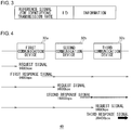
- FIG. 3 illustrates a format of a packet signal transmitted/received in the communication system 80.
- a reference signal for identifying a transmission rate an ID, and information are included in this order.
- the reference signal for identifying a transmission rate has a common value irrespective of the transmission rate, which will be described later.
- a command is included in the information.
- a field other than those illustrated in FIG. 3 may be disposed in the packet signal.
- the communication device 32 receives the packet signal and acquires an ID included in the received packet signal.
- the communication device 32 checks the acquired ID against an ID assigned to the communication device 32.
- the communication device 32 executes the command included in the received packet signal, and generates a packet signal including data of the result of the execution.
- the data corresponds to the physical amount described above and is included in the information in the packet signal.
- the communication device 32 transmits the generatedpacket signal to a succeeding communication device 32.
- the communication device 32 transfers the received packet signal to the succeeding communication device 32. In the manner as described above, each communication device 32 transmits the packet signal including data corresponding to the command included in the packet signal addressed thereto, and transfers the packet signal not addressed thereto.
- an amount of data to be transmitted is larger in a communication device 32 located closer to the ending point of the daisy chain connection than in a communication device 32 located closer to the starting point of the daisy chain connection.
- the amount of data to be transmitted is larger in the third communication device 32c than in the first communication device 32a.
- the packet signals to be transmitted by the first communication device 32a are a packet signal including data regarding the first battery pack 30a, and packet signals including commands for the second communication device 32b and the third communication device 32c, respectively.
- the packet signals to be transmitted by the third communication device 32c are packet signals including data regarding the first battery pack 30a, the second battery pack 30b, and the third battery pack 30c, respectively.
- the data amount in the packet signal including the data regarding the battery pack 30 is larger than that in the packet signal including the command.
- a light emitting diode (LED) for communication (not illustrated) is provided in the storage battery management unit 20 and each of the communication devices 32, and a packet signal is transmitted by blinking the LED for communication. Consequently, the larger the amount of data to be transmitted in the communication device 32, the larger the power consumption in the communication device 32.
- the power consumption is larger in the communication device 32 located closer to the ending point of the daisy chain connection than in the communication device 32 located closer to the starting point of the daisy chain connection.
- FIG. 4 illustrates an outline of processing performed by the communication system 80.
- the storage battery management unit 20 which is a starting point of the daisy chain connection
- the storage battery management unit 20 which is an ending point of the daisy chain connection
- a request signal which is a packet signal including the command described above, is transmitted from the storage battery management unit 20.
- the transmission rate in the transmission is 9600 bps.
- the first communication device 32a transmits, to the second communication device 32b, a first response signal, which is a packet signal including data corresponding to the command.
- the transmission rate in the transmission is 9600 bps.
- the first response signal is transferred by the second communication device 32b and the third communication device 32c, and reaches the storage battery management unit 20.
- the transmission rate in the transmission is maintained at 9600 bps, as well.
- the first communication device 32a transfers the request signal, and the second communication device 32b receives the request signal.
- the transmission rate in the transmission is maintained at 9600 bps, as well.
- the second communication device 32b transmits, to the third communication device 32c, a second response signal, which is a packet signal including data corresponding to the command.
- the transmission rate in the transmission is 19200 bps.
- the second response signal is transferred by the third communication device 32c, and reaches the storage battery management unit 20.
- the transmission rate in the transmission is maintained at 19200 bps, as well.
- the first communication device 32a and the second communication device 32b transfer the request signal, and the third communication device 32c receives the request signal.
- the transmission rate in the transmission is maintained at 9600 bps, as well.
- the third communication device 32c transmits, to the storage battery management unit 20, a third response signal, which is a packet signal including data corresponding to the command.
- the transmission rate in the transmission is 38400 bps.
- each of the communication devices 32 transfers the packet signal to the succeeding device in the daisy chain connection.
- the preceding device and the succeeding device correspond to the storage battery management unit 20 or another communication device 32.
- the communication device 32 transmits, to the succeeding device, a packet signal starting from the communication device 32 at a transmission rate higher than that used for the transfer. The closer the communication device 32 is located to the ending point in the daisy chain connection, the higher transmission rate the communication device 32 uses. Therefore, a time for transmission other than transfer is shortened, and an increase in power consumption is suppressed.
- the transmission rate of the packet signal starting from the first communication device 32a is two
- the transmission rate of the packet signal starting from the second communication device 32b is one
- the transmission rate of the packet signal starting from the third communication device 32c is zero. Therefore, the following expression is satisfied: the transmission rate of the packet signal starting from the first communication device 32a ⁇ the transmission rate of the packet signal starting from the second communication device 32b ⁇ the transmission rate of the packet signal starting from the third communication device 32c.
- the storage battery management unit 20 receives the packet signal from the third communication device 32c.
- the transmission rate of the packet signal is any one of 9600 bps, 19200 bps, and 38400 bps.
- the storage battery management unit 20 receives the packet signal at each of a plurality of kinds of transmission rates used in the daisy chain connection, and selects a transmission rate at which a reference signal for identifying a transmission rate has been detected. This processing will be described later.
- the storage battery management unit 20 acquires data included in the received packet signal, as described above.
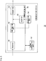
- FIG. 5 illustrates a configuration of the communication device 32.
- the communication device 32 includes a communication unit 50, a timing controlling unit 52, and a generation unit 54.
- the communication unit 50 includes a receiver 56, a confirmation unit 58, an acceptor 60, and a transmitter 62.
- the receiver 56 is a light-receiver, and receives a packet signal from another communication device 32 or the storage battery management unit 20 not illustrated, in other words, the preceding device in the daisy chain connection.
- the packet signal is an optical signal.
- the receiver 56 has an optical/electric (O/E) conversion function, and converts the packet signal from an optical signal to an electric signal.
- the receiver 56 outputs the packet signal which has been converted to the electric signal.
- the packet signal which has been converted to the electric signal is also referred to as a first signal.
- the first signal corresponds to the request signal or the response signal from another communication device 32 described above.
- the timing controlling unit 52 generates a timing at which the communication unit 50 operates. For the timing generation, a known technique may be used. Therefore, description thereof is omitted.
- the timing controlling unit 52 may generate a timing synchronized with the first signal, or a timing in accordance with the transmission rate higher than that of the first signal.
- FIGS. 6A to 6C illustrate an outline of an operation in the communication device 32.
- FIG. 6A illustrates a timing in accordance with a transmission rate of 9600 bps.
- a sampling timing is indicated by "T1" to "T6”.
- FIG. 6B illustrates a timing in accordance with a transmission rate of 19200 bps.
- a sampling timing is indicated by "U1" to "U11".
- FIG. 6C illustrates a timing in accordance with a transmission rate of 38400 bps.
- a sampling timing is indicated by "V1" to "V23".
- the sampling timings in a transmission rate of 9600 bps, a transmission rate of 19200 bps, and a transmission rate of 38400 bps are different from each other.
- FIG. 5 illustrates a timing in accordance with a transmission rate of 38400 bps.
- a sampling timing is indicated by "V1" to "V23”.
- the sampling timings in a transmission rate of 9600 bps, a transmission rate of 19200 bps, and a transmission rate of 38400 bps are different from each other.
- the confirmation unit 58 extracts an ID included in the packet signal from the receiver 56.
- the confirmation unit 58 confirms whether the extracted ID and the ID assigned to the communication device 32 are identical.
- the confirmation unit 58 outputs information included in the packet signal, in other words, a command, to the generation unit 54.
- the confirmation unit 58 outputs the packet signal to the transmitter 62. This corresponds to output of the first signal to the transmitter 62.
- the generation unit 54 accepts the command from the confirmation unit 58.
- the generation unit 54 acquires, from the battery pack 30 connected to the communication device 32, information corresponding to the command. As described above, when the command is acquisition of an SOC, the generation unit 54 accepts the SOC from the battery pack 30.
- the generation unit 54 stores the SOC as information, thereby generating a packet signal. At that time, as the ID, an ID assigned to the communication device 32 is used. It can also be said that the packet signal is a second signal starting from the communication device 32.
- the generation unit 54 outputs the generated packet signal to the acceptor 60.
- the acceptor 60 accepts the packet signal from the generation unit 54.
- the acceptor 60 determines a transmission rate of the packet signal, in other words, the second signal.
- a transmission rate higher than that of the first signal is used.
- the maximum value of the transmission rate of the first signal is 19200 bps
- a transmission rate of 38400 bps is used.
- the packet signal information regarding the battery pack 30 is included as the information.
- the acceptor 60 outputs the packet signal to the transmitter 62.
- the transmitter 62 accepts the packet signal from the confirmation unit 58, in other words, the first signal.
- the transmission rate of the first signal upon receiving is maintained. For example, when the transmission rate upon receiving is 9600 bps, a transmission rate of 9600 bps is used, and when the transmission rate upon receiving is 19200 bps, a transmission rate of 19200 bps is used.
- the transmitter 62 has an electric/optical (E/O) conversion function, and converts the first signal from an electric signal to an optical signal.
- the transmitter 62 transmits the first signal to another communication device 32 or the storage battery management unit 20 not illustrated, in other words, the succeeding device in the daisy chain connection.
- the transmitter 62 accepts the packet signal from the acceptor 60, in other words, the second signal.
- the transmitter 62 converts the second signal from an electric signal to an optical signal.
- the transmitter 62 transmits the second signal to another communication device 32 or the storage battery management unit 20 not illustrated, in other words, the succeeding device in the daisy chain connection.
- the configuration can be realized, as hardware, by a CPU, a memory, and other LSI of any computer, and as software, by a program loaded in a memory, and the like.
- a functional block realized by cooperation of the above components is illustrated. Therefore, it is understood by a person skilled in the art that the functional block can be realized in various ways, for example, by only the hardware, or a combination of the hardware and the software.
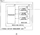
- FIG. 7 illustrates a configuration of the storage battery management unit 20.
- the storage battery management unit 20 includes a receiving device 70 and a processor 74.
- the receiving device 70 includes a first receiver 72a, a second receiver 72b, and a third receiver 72c.
- the first receiver 72a, the second receiver 72b, and the third receiver 72c may be collectively referred to as a receiver 72.
- the receiver 72 receives a packet signal from each of the communication devices 32 included in the daisy chain connection.
- the receiver 72 converts the packet signal from an optical signal to an electric signal.
- a plurality of kinds of the transmission rates is used for the packet signal. In other words, there are cases using, as a transmission rate, 9600 bps, 19200 bps, and 38400 bps.
- the first receiver 72a processes the packet signal at a rate of 9600 bps. This corresponds to sampling at a timing of "T1" to "T6" of FIG. 6A .
- the second receiver 72b processes the packet signal at a rate of 19200 bps and the third receiver 72c processes the packet signal at a rate of 38400 bps. These correspond to sampling at a timing of "U1" to "U11" of FIG. 6B , and sampling at a timing of "V1" to “V23” of FIG. 6C , respectively.
- a reference signal for identifying a transmission rate is included in the packet signal.
- the reference signal for identifying a transmission rate has a common value irrespective of the transmission rate. Consequently, an accurate value of the reference signal for identifying a transmission rate is output from one of the first receiver 72a to the third receiver 72c, which uses a transmission rate identical with the transmission rate of the received packet signal.
- the receiver 72 selects, from the plurality of kinds of the transmission rates, a transmission rate at which the accurate value of the reference signal for identifying a transmission rate is output.
- the receiver 72 outputs, to the processor 74, the packet signal sampled based on the selected transmission rate.
- the processor 74 processes the packet signal from the receiver 72. In other words, the processor 74 extracts the ID and the information included in the packet signal, and performs control thereof as described above.
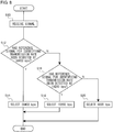
- FIG. 8 is a flowchart illustrating a receiving procedure performed by the storage battery management unit 20.
- the receiver 72 receives a packet signal (S10).
- a reference signal for identifying a transmission rate has been detected at a rate of 38400 bps (Y in S12)
- the receiver 72 selects 38400 bps (S14).
- the reference signal for identifying a transmission rate has not been detected at a rate of 38400 bps (N in S12), and has been detected at a rate of 19200 bps (Y in S16)
- the receiver 72 selects 19200 bps (S18).
- the receiver 72 selects 9600 bps (S20).
- a new packet signal is transmitted at a transmission rate higher than the transmission rate. Therefore, a time required for transmitting the new packet signal can be shortened. In addition, since the time required for transmitting the new packet signal is shortened, a transmission period added to a succeeding communication device in a daisy chain connection can be shortened. In addition, since the transmission period added to the succeeding communication device in the daisy chain connection is shortened, a difference in power consumption between the preceding and succeeding communication devices in the daisy chain connection can be reduced. In addition, since the difference in power consumption between the preceding and succeeding communication devices in the daisy chain connection is reduced, power consumption in the daisy chain connection can be leveled.
- a plurality of battery packs can be controlled.
- the reference signal for identifying a transmission rate which signal has a common value irrespective of the transmission rate, is included in the packet signal, the reference signal for identifying a transmission rate can be used for determining a transmission rate.
- the transmission rate can be determined automatically.
- a communication device 32 in an aspect of the present invention is included in a daisy chain connection, and includes a receiver 56, a transmitter 62, and an acceptor 60.
- the receiver 56 receives a first signal from a preceding device in the daisy chain connection
- the transmitter 62 transmits the first signal received in the receiver 56 to a succeeding device in the daisy chain connection
- the acceptor 60 accepts a second signal starting from the communication device 32.
- the transmitter 62 transmits the second signal to the succeeding device at a transmission rate higher than that of the first signal.
- the transmitter 62 may maintain the transmission rate of the first signal when transmitting the first signal received in the receiver 56 to the succeeding device in the daisy chain connection.
- the acceptor 60 may determine a transmission rate.
- the communication device 32 is connected to the battery pack 30, and information regarding the battery pack 30 is included in the second signal accepted in the acceptor 60.
- a reference signal for identifying a transmission rate which signal has a common value, is included.
- the device includes a receiver 72 and a processor 74.
- the receiver 72 receives a signal from each of a plurality of communication devices 32 included in a daisy chain connection, for which signal a plurality of kinds of transmission rates is used.
- the processor 74 processes the signal received in the receiver 72.
- a reference signal for identifying a transmission rate which signal has a common value irrespective of the transmission rate, is included.
- the receiver 72 receives the signal at each of the plurality of kinds of transmission rates, and selects a transmission rate at which the reference signal for identifying a transmission rate has been detected.
- Still another aspect of the present invention is a communication system 80.
- the communication system 80 includes a storage battery management unit 20, and a plurality of communication devices 32 daisy-chained from the storage battery management unit 20.
- Each of the plurality of communication devices 32 transfers a signal received from a preceding device in the daisy chain connection to a succeeding device in the daisy chain connection, and transmits, to the succeeding device, a signal starting from the communication device 32 at a transmission rate higher than that used for the transfer.
- a reference signal for identifying a transmission rate which signal has a common value irrespective of the transmission rate, is included in the signal in the daisy chain connection.
- the storage battery management unit 20 may receive the signal at each of a plurality of kinds of transmission rates used in the daisy chain connection, and select a transmission rate at which the reference signal for identifying a transmission rate has been detected.
- the transmission rate is not limited thereto, and values other than the above may be employed.
- the number of kinds of the transmission rates may not necessarily be three. According to the modification, the degree of freedom of a configuration can be increased.
- different transmission rates are used for the packet signals starting from a plurality of the daisy-chained communication devices 32.
- the same transmission rate may be used for the packet signals starting from adjacent communication devices 32.
- a larger number of communication devices 32 than the number of kinds of the transmission rates can be daisy-chained.
- the communication system 80 is connected to the battery pack 30, and transmits information regarding the battery pack 30.
- the communication system 80 may not necessarily be connected to the battery pack 30. According to the modification, the communication system 80 can transmit any information.
Landscapes
- Engineering & Computer Science (AREA)
- Physics & Mathematics (AREA)
- General Physics & Mathematics (AREA)
- Theoretical Computer Science (AREA)
- Computer Networks & Wireless Communication (AREA)
- General Engineering & Computer Science (AREA)
- Small-Scale Networks (AREA)
- Signal Processing (AREA)
Abstract
Description
- This application is based upon and claims the benefit of priority from the prior Japanese Patent Application No.
2015-50143, filed on March 13, 2015 - The disclosure relates to communication technology, and particularly to a communication device, a receiving device, and a communication system for transmitting information in a daisy chain network.
- In order to transmit voltage values of a plurality of battery cells to a microcomputer, a communication interface is provided in each of the battery cells. A plurality of communication interfaces is serially connected, and each of the communication interfaces transfers the voltage values (refer to
WO 11/043311 A - As a connection mode for transmitting voltage values of a plurality of battery cells to a microcomputer, there is a daisy chain connection. In the daisy chain connection, a plurality of communication interfaces is connected in an annular pattern like one ring. For example, a daisy chain connection starting from a management device returns to the management device as an ending point via a plurality of communication interfaces. Consequently, in a communication interface located closer to the ending point, there is an increasing amount of information received from other communication interface and to be transferred, and a transfer amount is larger than that in a communication interface located closer to the starting point. Accordingly, power consumption in a communication interface located closer to the ending point is larger than that in a communication interface located closer to the starting point.
- The present invention has been made in view of the situation described above, and an object of the present invention is to provide a technique with which power consumption in a daisy chain connection is leveled.
- In order to solve the above problem, a communication device in an aspect of the present invention is included in a daisy chain connection, and includes a receiver, a transmitter, and an acceptor. The receiver receives a first signal from a preceding device in the daisy chain connection, the transmitter transmits the first signal received in the receiver to a succeeding device in the daisy chain connection, and the acceptor accepts a second signal starting from the communication device. The transmitter transmits the second signal to the succeeding device at a transmission rate higher than that of the first signal.
- Another aspect of the present invention is a receiving device. The device includes a receiver and a processor. The receiver receives a signal from each of a plurality of communication devices included in a daisy chain connection, for which signal a plurality of kinds of transmission rates is used. The processor processes the signal received in the receiver. A reference signal for identifying a transmission rate, which signal has a common value irrespective of the transmission rate, is included in the signal received in the receiver. The receiver receives the signal at each of the plurality of kinds of transmission rates, and selects a transmission rate at which the reference signal for identifying a transmission rate has been detected.
- Still another aspect of the present invention is a communication system. The communication system includes a management device, and a plurality of communication devices daisy-chained from the management device. Each of the plurality of communication devices transfers a signal received from a preceding device in the daisy chain connection to a succeeding device in the daisy chain connection, and transmits, to the succeeding device, a signal starting from the communication device at a transmission rate higher than that used for the transfer.
- Any combination of the above components, those in which the expression in the present invention has been converted among methods, devices, systems, and the like, are also effective as an aspect of the present invention.
- The figures depict one or more implementations in accordance with the present teaching, by way of example only, not by way of limitations. In the figures, like reference numerals refer to the same or similar elements.
-
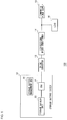
FIG. 1 is a diagram illustrating a configuration of a power distribution system according to an embodiment of the present invention; -
FIG. 2 is a diagram illustrating a connection between a storage battery unit and a storage battery management unit ofFIG. 1 ; -
FIG. 3 is a diagram illustrating a format of a packet signal transmitted/received in a communication system ofFIG. 2 ; -
FIG. 4 is a diagram illustrating an outline of processing performed by the communication system ofFIG. 2 ; -
FIG. 5 is a diagram illustrating a configuration of the communication device ofFIG. 2 ; -
FIGS. 6A to 6C are diagrams illustrating an outline of an operation in the communication device ofFIG. 5 ; -
FIG. 7 is a diagram illustrating a configuration of the storage battery management unit ofFIG. 2 ; and -
FIG. 8 is a flowchart illustrating a receiving procedure performed by the storage battery management unit ofFIG. 7 . - The invention will now be described by reference to the preferred embodiments. This does not intend to limit the scope of the present invention, but to exemplify the invention.
- Prior to specific description of the present invention, an outline thereof is described. An embodiment of the present invention relates to a communication system in which communication devices provided in a plurality of battery packs, respectively, are daisy-chained. In the daisy chain connection, a communication device transmits a packet signal including predetermined information to a succeeding communication device. The succeeding communication device transmits a new packet signal including predetermined information to a communication device further succeeding the succeeding communication device, and transfers the packet signal received from the preceding communication device to the communication device further succeeding the succeeding communication device.
- In the manner described above, each communication device performs, in addition to transmission of a new packet signal, transfer of a packet signal. Accordingly, a communication time required for transmission of a packet signal is longer in a communication device located closer to the ending point of the daisy chain connection, than in a communication device located closer to the starting point thereof.
- In a case of performing optical communication for transmitting and transferring a packet signal, the longer a communication time, the longer a light-emitting time, and accordingly, power consumption increases. Power is supplied to the communication device by a battery pack. Therefore, a remaining battery power varies among battery packs depending on a difference in power consumption. In a case where a power storage system is formed by connecting a plurality of battery packs, in general, a remaining battery power in each battery pack is preferably leveled among the battery packs, and it is not preferable that the remaining battery power in each battery pack vary among the battery packs as a result of communication.
- In order to deal with this problem, the communication device according to the embodiment uses a transmission rate for transferring a packet signal from a communication device located closer to an ending point of a daisy chain connection, which transmission rate is higher than a transmission rate for transferring a packet signal from a communication device located closer to a starting point thereof. For example, a communication device located closer to the starting point (hereinafter referred to as "first communication device") transmits a packet signal at a transmission rate of 9600 bps, and other communication devices in the daisy chain connection transfer the packet signal at a transmission rate of 9600 bps. On the other hand, a communication device located closer to the ending point than the first communication device (hereinafter referred to as "second communication device") transmits a packet signal at a transmission rate of 19200 bps, which is higher than 9600 bps. In addition, the second communication device transfers the packet signal from the first communication device at a transmission rate of 9600 bps, as described above.
- In
FIG. 1 , a configuration of apower distribution system 100 according to the embodiment of the present invention is illustrated. Thepower distribution system 100 includes astorage battery system 10, a DC/DC converter 12, abidirectional power conditioner 14, aload 16, and acommercial power supply 18. Thestorage battery system 10 includes a storagebattery management unit 20, astorage battery unit 22, and a switch (SW) 24. - The
commercial power supply 18 is an AC power supply and power is supplied from a power company. Thestorage battery system 10 includes thestorage battery unit 22 which includes a plurality of battery packs not illustrated. Here, for the sake of clearer description, onestorage battery unit 22 is provided. However, a plurality of thestorage battery units 22 may be provided. TheSW 24 is provided between thestorage battery unit 22 and the DC/DC converter 12, and connects and disconnects a conductive path between thestorage battery unit 22 and the DC/DC converter 12. The storagebattery management unit 20 manages each battery pack included in thestorage battery unit 22, and also manages an operation of theSW 24. The management of thestorage battery unit 22 by the storagebattery management unit 20 will be described later. - The DC/
DC converter 12 is disposed in a conductive path between theSW 24 and thebidirectional power conditioner 14, steps up or steps down the DCpower converted by thebidirectional power conditioner 14, and causes thestorage battery system 10 to charge or discharge power. - One end of the
bidirectional power conditioner 14 is connected to the DC/DC converter 12, and another end thereof is connected to thecommercial power supply 18. Thebidirectional power conditioner 14 includes a bidirectional inverter not illustrated. The inverter converts, to AC power, the DC power from the DC/DC converter 12, which DC power is discharged by thestorage battery system 10, and outputs the AC power to theload 16. On the other hand, the inverter converts the AC power from thecommercial power supply 18 to DC power, and outputs the DC power to the DC/DC converter 12. Theload 16 operates when AC power is supplied thereto from thecommercial power supply 18 or thebidirectional power conditioner 14. -
FIG. 2 illustrates a connection between thestorage battery unit 22 and the storagebattery management unit 20. Thestorage battery unit 22 includes afirst battery pack 30a, asecond battery pack 30b, and athird battery pack 30c, which are collectively referred to as a battery pack 30, as well as afirst terminal 40a and asecond terminal 40b, which are collectively referred to as a terminal 40. Thefirst battery pack 30a includes afirst communication device 32a, afirst storage battery 34a, asecond storage battery 34b, athird storage battery 34c, afourth storage battery 34d, afifth storage battery 34e, a firstpositive electrode terminal 36a, and a firstnegative electrode terminal 38a. Thesecond battery pack 30b includes asecond communication device 32b, asixth storage battery 34f, aseventh storage battery 34g, aneighth storage battery 34h, aninth storage battery 34i, atenth storage battery 34j , a secondpositive electrode terminal 36b, and a secondnegative electrode terminal 38b. Thethird battery pack 30c includes athird communication device 32c, aneleventh storage battery 34k, atwelfth storage battery 341, athirteenth storage battery 34m, afourteenth storage battery 34n, a fifteenth storage battery 34o, a thirdpositive electrode terminal 36c, and a thirdnegative electrode terminal 38c. - Here, the
first communication device 32a, thesecond communication device 32b, and thethird communication device 32c are collectively referred to as acommunication device 32. Thefirst storage battery 34a to the fifteenth storage battery 34o are collectively referred to as a storage battery 34. The firstpositive electrode terminal 36a, the secondpositive electrode terminal 36b, and the thirdpositive electrode terminal 36c are collectively referred to as a positive electrode terminal 36. The firstnegative electrode terminal 38a, the secondnegative electrode terminal 38b, and the thirdnegative electrode terminal 38c are collectively referred to as a negative electrode terminal 38. Acommunication system 80 includes the storagebattery management unit 20, thefirst communication device 32a, thesecond communication device 32b, and thethird communication device 32c. Thestorage battery unit 22 includes three battery packs 30, and the battery pack 30 includes five storage batteries 34. However, the number of the battery packs 30 included in thestorage battery unit 22, and the number of the storage batteries 34 included in the battery pack 30 are not limited to the above numbers. - In each of the battery packs 30, five storage batteries 34 are connected in parallel. A positive electrode of the storage battery 34 is connected to the positive electrode terminal 36, and a negative electrode of the storage battery 34 is connected to the negative electrode terminal 38. In addition, the positive electrode terminal 36 and the negative electrode terminal 38 are connected between adjacent storage batteries 34 in such a way that the first
negative electrode terminal 38a and the secondpositive electrode terminal 36b are connected, and the secondnegative electrode terminal 38b and the thirdpositive electrode terminal 36c are connected. By the connection described above, three combinations of parallel-connected five storage batteries 34 are connected in series. In addition, these are connected to afirst terminal 40a and asecond terminal 40b. Furthermore, thefirst terminal 40a and thesecond terminal 40b are connected to theSW 24 not illustrated. InFIG. 2 , thestorage battery unit 22 is connected to theSW 24 by twoterminals 40. InFIG. 1 , however, thestorage battery unit 22 is connected to theSW 24 by one line. This is simply a difference in notation caused by a difference betweenFIG. 2 andFIG. 1 . The positive electrode and the negative electrode are distinguished from each other inFIG. 2 , but not inFIG. 1 . - The storage
battery management unit 20 acquires various physical amounts of the battery pack 30, such as a state of charge (SOC) and a temperature of each battery pack 30, and provides the acquired physical amounts to thebidirectional power conditioner 14 not illustrated. In addition, the storagebattery management unit 20 controls the battery pack 30 based on the acquired physical amounts. For example, the storagebattery management unit 20 controls a fan (not illustrated) for cooling the battery pack 30 to cool the battery pack 30. As described above, the storagebattery management unit 20 functions as a management device for controlling the battery pack 30. - In the
communication system 80, a plurality of thecommunication devices 32 is daisy-chained from the storagebattery management unit 20. Specifically, the storagebattery management unit 20 connects to thefirst communication device 32a, thefirst communication device 32a connects to thesecond communication device 32b, thesecond communication device 32b connects to thethird communication device 32c, and thethird communication device 32c connects to the storagebattery management unit 20. In a manner described above, the storagebattery management unit 20, thefirst communication device 32a, thesecond communication device 32b, thethird communication device 32c, and the storagebattery management unit 20 are connected in a row in this order, whereby a daisy chain connection is formed. - In the daisy chain connection, an optical fiber is used in a path between the storage
battery management unit 20 and thecommunication device 32, and a path betweenadjacent communication devices 32. The storagebattery management unit 20 performs optical communication with eachcommunication device 32 by using a predetermined communication protocol. A unique address (hereinafter referred to as "ID") is assigned to eachcommunication device 32. The storagebattery management unit 20 identifies eachcommunication device 32 using the ID. The storagebattery management unit 20 transmits, to thecommunication device 32, a packet signal including the ID and a command for identifying a physical amount to be acquired, in accordance with the predetermined communication protocol. -
FIG. 3 illustrates a format of a packet signal transmitted/received in thecommunication system 80. In the packet signal, a reference signal for identifying a transmission rate, an ID, and information are included in this order. The reference signal for identifying a transmission rate has a common value irrespective of the transmission rate, which will be described later. In the information, for example, a command is included. A field other than those illustrated inFIG. 3 may be disposed in the packet signal. Return toFIG. 2 . - When the storage
battery management unit 20 transmits a packet signal to thecommunication device 32, thecommunication device 32 receives the packet signal and acquires an ID included in the received packet signal. Thecommunication device 32 checks the acquired ID against an ID assigned to thecommunication device 32. When the acquired ID and the assigned ID are identical, thecommunication device 32 executes the command included in the received packet signal, and generates a packet signal including data of the result of the execution. The data corresponds to the physical amount described above and is included in the information in the packet signal. Thecommunication device 32 transmits the generatedpacket signal to a succeedingcommunication device 32. On the other hand, when the acquired ID and the ID assigned to thecommunication device 32 are not identical, thecommunication device 32 transfers the received packet signal to the succeedingcommunication device 32. In the manner as described above, eachcommunication device 32 transmits the packet signal including data corresponding to the command included in the packet signal addressed thereto, and transfers the packet signal not addressed thereto. - In an environment of such an annular daisy chain connection, an amount of data to be transmitted is larger in a
communication device 32 located closer to the ending point of the daisy chain connection than in acommunication device 32 located closer to the starting point of the daisy chain connection. Specifically, the amount of data to be transmitted is larger in thethird communication device 32c than in thefirst communication device 32a. The packet signals to be transmitted by thefirst communication device 32a are a packet signal including data regarding thefirst battery pack 30a, and packet signals including commands for thesecond communication device 32b and thethird communication device 32c, respectively. On the other hand, the packet signals to be transmitted by thethird communication device 32c are packet signals including data regarding thefirst battery pack 30a, thesecond battery pack 30b, and thethird battery pack 30c, respectively. The data amount in the packet signal including the data regarding the battery pack 30 is larger than that in the packet signal including the command. - Since optical communication is used for the communication in the
communication system 80, a light emitting diode (LED) for communication (not illustrated) is provided in the storagebattery management unit 20 and each of thecommunication devices 32, and a packet signal is transmitted by blinking the LED for communication. Consequently, the larger the amount of data to be transmitted in thecommunication device 32, the larger the power consumption in thecommunication device 32. Here, the power consumption is larger in thecommunication device 32 located closer to the ending point of the daisy chain connection than in thecommunication device 32 located closer to the starting point of the daisy chain connection. - In order to reduce the imbalance in the power consumption among the
communication devices 32, thecommunication system 80 executes the following processing.FIG. 4 illustrates an outline of processing performed by thecommunication system 80. Here, only thefirst communication device 32a, thesecond communication device 32b, and thethird communication device 32c inFIG. 2 are illustrated. To the left side of thefirst communication device 32a, the storagebattery management unit 20 which is a starting point of the daisy chain connection is disposed, and to the right side of thethird communication device 32c, the storagebattery management unit 20 which is an ending point of the daisy chain connection is disposed. A request signal, which is a packet signal including the command described above, is transmitted from the storagebattery management unit 20. The transmission rate in the transmission is 9600 bps. In a case where the request signal is addressed to thefirst communication device 32a, thefirst communication device 32a transmits, to thesecond communication device 32b, a first response signal, which is a packet signal including data corresponding to the command. The transmission rate in the transmission is 9600 bps. The first response signal is transferred by thesecond communication device 32b and thethird communication device 32c, and reaches the storagebattery management unit 20. The transmission rate in the transmission is maintained at 9600 bps, as well. - In a case where the request signal is addressed to the
second communication device 32b, thefirst communication device 32a transfers the request signal, and thesecond communication device 32b receives the request signal. The transmission rate in the transmission is maintained at 9600 bps, as well. Thesecond communication device 32b transmits, to thethird communication device 32c, a second response signal, which is a packet signal including data corresponding to the command. The transmission rate in the transmission is 19200 bps. The second response signal is transferred by thethird communication device 32c, and reaches the storagebattery management unit 20. The transmission rate in the transmission is maintained at 19200 bps, as well. In a case where the request signal is addressed to thethird communication device 32c, thefirst communication device 32a and thesecond communication device 32b transfer the request signal, and thethird communication device 32c receives the request signal. The transmission rate in the transmission is maintained at 9600 bps, as well. Thethird communication device 32c transmits, to the storagebattery management unit 20, a third response signal, which is a packet signal including data corresponding to the command. The transmission rate in the transmission is 38400 bps. - As described above, while maintaining the transmission rate of the packet signal received from the preceding device in the daisy chain connection, each of the
communication devices 32 transfers the packet signal to the succeeding device in the daisy chain connection. The preceding device and the succeeding device correspond to the storagebattery management unit 20 or anothercommunication device 32. In addition, thecommunication device 32 transmits, to the succeeding device, a packet signal starting from thecommunication device 32 at a transmission rate higher than that used for the transfer. The closer thecommunication device 32 is located to the ending point in the daisy chain connection, the higher transmission rate thecommunication device 32 uses. Therefore, a time for transmission other than transfer is shortened, and an increase in power consumption is suppressed. - When a packet signal is transferred by the
communication device 32, a waveform of the signal is distorted. The distortion is increased in proportion to the number of times of transfer. When the distortion is increased, an error is more likely to occur in transmission of the packet signal. It is effective to decrease the transmission rate to reduce the probability of the error. Here, the number of times of transfer of the packet signal starting from thefirst communication device 32a is two, the number of times of transfer of the packet signal starting from thesecond communication device 32b is one, and the number of times of transfer of the packet signal starting from thethird communication device 32c is zero. Therefore, the following expression is satisfied: the transmission rate of the packet signal starting from thefirst communication device 32a < the transmission rate of the packet signal starting from thesecond communication device 32b < the transmission rate of the packet signal starting from thethird communication device 32c. - The storage
battery management unit 20 receives the packet signal from thethird communication device 32c. The transmission rate of the packet signal is any one of 9600 bps, 19200 bps, and 38400 bps. The storagebattery management unit 20 receives the packet signal at each of a plurality of kinds of transmission rates used in the daisy chain connection, and selects a transmission rate at which a reference signal for identifying a transmission rate has been detected. This processing will be described later. The storagebattery management unit 20 acquires data included in the received packet signal, as described above. -
FIG. 5 illustrates a configuration of thecommunication device 32. Thecommunication device 32 includes acommunication unit 50, atiming controlling unit 52, and a generation unit 54. Thecommunication unit 50 includes areceiver 56, aconfirmation unit 58, anacceptor 60, and atransmitter 62. Thereceiver 56 is a light-receiver, and receives a packet signal from anothercommunication device 32 or the storagebattery management unit 20 not illustrated, in other words, the preceding device in the daisy chain connection. The packet signal is an optical signal. In addition, thereceiver 56 has an optical/electric (O/E) conversion function, and converts the packet signal from an optical signal to an electric signal. Thereceiver 56 outputs the packet signal which has been converted to the electric signal. Here, the packet signal which has been converted to the electric signal is also referred to as a first signal. The first signal corresponds to the request signal or the response signal from anothercommunication device 32 described above. - The
timing controlling unit 52 generates a timing at which thecommunication unit 50 operates. For the timing generation, a known technique may be used. Therefore, description thereof is omitted. Thetiming controlling unit 52 may generate a timing synchronized with the first signal, or a timing in accordance with the transmission rate higher than that of the first signal.FIGS. 6A to 6C illustrate an outline of an operation in thecommunication device 32.FIG. 6A illustrates a timing in accordance with a transmission rate of 9600 bps. Here, a sampling timing is indicated by "T1" to "T6".FIG. 6B illustrates a timing in accordance with a transmission rate of 19200 bps. Here, a sampling timing is indicated by "U1" to "U11".FIG. 6C illustrates a timing in accordance with a transmission rate of 38400 bps. Here, a sampling timing is indicated by "V1" to "V23". According toFIGS. 6A to 6C , the sampling timings in a transmission rate of 9600 bps, a transmission rate of 19200 bps, and a transmission rate of 38400 bps are different from each other. Return toFIG. 5 . - The
confirmation unit 58 extracts an ID included in the packet signal from thereceiver 56. Theconfirmation unit 58 confirms whether the extracted ID and the ID assigned to thecommunication device 32 are identical. When the IDs are identical, theconfirmation unit 58 outputs information included in the packet signal, in other words, a command, to the generation unit 54. On the other hand, when the IDs are not identical, theconfirmation unit 58 outputs the packet signal to thetransmitter 62. This corresponds to output of the first signal to thetransmitter 62. - The generation unit 54 accepts the command from the
confirmation unit 58. The generation unit 54 acquires, from the battery pack 30 connected to thecommunication device 32, information corresponding to the command. As described above, when the command is acquisition of an SOC, the generation unit 54 accepts the SOC from the battery pack 30. The generation unit 54 stores the SOC as information, thereby generating a packet signal. At that time, as the ID, an ID assigned to thecommunication device 32 is used. It can also be said that the packet signal is a second signal starting from thecommunication device 32. The generation unit 54 outputs the generated packet signal to theacceptor 60. Theacceptor 60 accepts the packet signal from the generation unit 54. Theacceptor 60 determines a transmission rate of the packet signal, in other words, the second signal. Here, for the second signal, a transmission rate higher than that of the first signal is used. For example, when the maximum value of the transmission rate of the first signal is 19200 bps, a transmission rate of 38400 bps is used. In the packet signal, information regarding the battery pack 30 is included as the information. Theacceptor 60 outputs the packet signal to thetransmitter 62. - The
transmitter 62 accepts the packet signal from theconfirmation unit 58, in other words, the first signal. For the first signal, the transmission rate of the first signal upon receiving is maintained. For example, when the transmission rate upon receiving is 9600 bps, a transmission rate of 9600 bps is used, and when the transmission rate upon receiving is 19200 bps, a transmission rate of 19200 bps is used. In addition, thetransmitter 62 has an electric/optical (E/O) conversion function, and converts the first signal from an electric signal to an optical signal. Thetransmitter 62 transmits the first signal to anothercommunication device 32 or the storagebattery management unit 20 not illustrated, in other words, the succeeding device in the daisy chain connection. - Separately, the
transmitter 62 accepts the packet signal from theacceptor 60, in other words, the second signal. Thetransmitter 62 converts the second signal from an electric signal to an optical signal. Thetransmitter 62 transmits the second signal to anothercommunication device 32 or the storagebattery management unit 20 not illustrated, in other words, the succeeding device in the daisy chain connection. - The configuration can be realized, as hardware, by a CPU, a memory, and other LSI of any computer, and as software, by a program loaded in a memory, and the like. Here, a functional block realized by cooperation of the above components is illustrated. Therefore, it is understood by a person skilled in the art that the functional block can be realized in various ways, for example, by only the hardware, or a combination of the hardware and the software.
-
FIG. 7 illustrates a configuration of the storagebattery management unit 20. The storagebattery management unit 20 includes a receivingdevice 70 and aprocessor 74. The receivingdevice 70 includes afirst receiver 72a, asecond receiver 72b, and athird receiver 72c. Thefirst receiver 72a, thesecond receiver 72b, and thethird receiver 72c may be collectively referred to as areceiver 72. - The
receiver 72 receives a packet signal from each of thecommunication devices 32 included in the daisy chain connection. Thereceiver 72, as with thereceiver 56, converts the packet signal from an optical signal to an electric signal. A plurality of kinds of the transmission rates is used for the packet signal. In other words, there are cases using, as a transmission rate, 9600 bps, 19200 bps, and 38400 bps. Thefirst receiver 72a processes the packet signal at a rate of 9600 bps. This corresponds to sampling at a timing of "T1" to "T6" ofFIG. 6A . - The
second receiver 72b processes the packet signal at a rate of 19200 bps and thethird receiver 72c processes the packet signal at a rate of 38400 bps. These correspond to sampling at a timing of "U1" to "U11" ofFIG. 6B , and sampling at a timing of "V1" to "V23" ofFIG. 6C , respectively. As described above, a reference signal for identifying a transmission rate is included in the packet signal. The reference signal for identifying a transmission rate has a common value irrespective of the transmission rate. Consequently, an accurate value of the reference signal for identifying a transmission rate is output from one of thefirst receiver 72a to thethird receiver 72c, which uses a transmission rate identical with the transmission rate of the received packet signal. Thereceiver 72 selects, from the plurality of kinds of the transmission rates, a transmission rate at which the accurate value of the reference signal for identifying a transmission rate is output. Thereceiver 72 outputs, to theprocessor 74, the packet signal sampled based on the selected transmission rate. Theprocessor 74 processes the packet signal from thereceiver 72. In other words, theprocessor 74 extracts the ID and the information included in the packet signal, and performs control thereof as described above. - An operation of the
power distribution system 100 having the above configuration is described.FIG. 8 is a flowchart illustrating a receiving procedure performed by the storagebattery management unit 20. Thereceiver 72 receives a packet signal (S10). When a reference signal for identifying a transmission rate has been detected at a rate of 38400 bps (Y in S12), thereceiver 72 selects 38400 bps (S14). When the reference signal for identifying a transmission rate has not been detected at a rate of 38400 bps (N in S12), and has been detected at a rate of 19200 bps (Y in S16), thereceiver 72 selects 19200 bps (S18). When the reference signal for identifying a transmission rate has not been detected at a rate of 19200 bps (N in S16), thereceiver 72 selects 9600 bps (S20). - According to the embodiment of the present invention, while maintaining a transmission rate for a packet signal to be transferred, a new packet signal is transmitted at a transmission rate higher than the transmission rate. Therefore, a time required for transmitting the new packet signal can be shortened. In addition, since the time required for transmitting the new packet signal is shortened, a transmission period added to a succeeding communication device in a daisy chain connection can be shortened. In addition, since the transmission period added to the succeeding communication device in the daisy chain connection is shortened, a difference in power consumption between the preceding and succeeding communication devices in the daisy chain connection can be reduced. In addition, since the difference in power consumption between the preceding and succeeding communication devices in the daisy chain connection is reduced, power consumption in the daisy chain connection can be leveled.
- In addition, the closer to the starting point in the daisy chain connection, the lower transmission rate is used. Therefore, the effect of the distortion can be reduced. In addition, since the effect of the distortion is reduced, occurrence of an error can be suppressed even if the number of times of transfer is large. In addition, since the information regarding the battery pack is transmitted through the daisy chain connection, a plurality of battery packs can be controlled. In addition, since a reference signal for identifying a transmission rate, which signal has a common value irrespective of the transmission rate, is included in the packet signal, the reference signal for identifying a transmission rate can be used for determining a transmission rate. In addition, since a signal is received at each of a plurality of kinds of transmission rates and a transmission rate at which a reference signal for identifying a transmission rate has been detected is selected, the transmission rate can be determined automatically.
- An outline of an aspect of the present invention is as follows. A
communication device 32 in an aspect of the present invention is included in a daisy chain connection, and includes areceiver 56, atransmitter 62, and anacceptor 60. Thereceiver 56 receives a first signal from a preceding device in the daisy chain connection, thetransmitter 62 transmits the first signal received in thereceiver 56 to a succeeding device in the daisy chain connection, and theacceptor 60 accepts a second signal starting from thecommunication device 32. Thetransmitter 62 transmits the second signal to the succeeding device at a transmission rate higher than that of the first signal. - The
transmitter 62 may maintain the transmission rate of the first signal when transmitting the first signal received in thereceiver 56 to the succeeding device in the daisy chain connection. - The
acceptor 60 may determine a transmission rate. - The
communication device 32 is connected to the battery pack 30, and information regarding the battery pack 30 is included in the second signal accepted in theacceptor 60. - In the first signal and the second signal transmitted from the
transmitter 62, a reference signal for identifying a transmission rate, which signal has a common value, is included. - Another aspect of the present invention is a receiving
device 70. The device includes areceiver 72 and aprocessor 74. Thereceiver 72 receives a signal from each of a plurality ofcommunication devices 32 included in a daisy chain connection, for which signal a plurality of kinds of transmission rates is used. Theprocessor 74 processes the signal received in thereceiver 72. In the signal received in thereceiver 72, a reference signal for identifying a transmission rate, which signal has a common value irrespective of the transmission rate, is included. Thereceiver 72 receives the signal at each of the plurality of kinds of transmission rates, and selects a transmission rate at which the reference signal for identifying a transmission rate has been detected. - Still another aspect of the present invention is a
communication system 80. Thecommunication system 80 includes a storagebattery management unit 20, and a plurality ofcommunication devices 32 daisy-chained from the storagebattery management unit 20. Each of the plurality ofcommunication devices 32 transfers a signal received from a preceding device in the daisy chain connection to a succeeding device in the daisy chain connection, and transmits, to the succeeding device, a signal starting from thecommunication device 32 at a transmission rate higher than that used for the transfer. - A reference signal for identifying a transmission rate, which signal has a common value irrespective of the transmission rate, is included in the signal in the daisy chain connection. The storage
battery management unit 20 may receive the signal at each of a plurality of kinds of transmission rates used in the daisy chain connection, and select a transmission rate at which the reference signal for identifying a transmission rate has been detected. - The present invention has been described above based on the embodiment. The embodiment is for illustrative purposes, and it is understood by a person skilled in the art that various modifications are possible for combinations of respective components or respective processing processes thereof, and that such modifications are also included in the scope of the present invention.
- In the embodiment of the present invention, there are three kinds of transmission rates, i.e. 9600 bps, 19200 bps, and 38400 bps. However, the transmission rate is not limited thereto, and values other than the above may be employed. In addition, the number of kinds of the transmission rates may not necessarily be three. According to the modification, the degree of freedom of a configuration can be increased.
- In the embodiment of the present invention, different transmission rates are used for the packet signals starting from a plurality of the daisy-chained
communication devices 32. However, there is no limitation thereto. For example, the same transmission rate may be used for the packet signals starting fromadjacent communication devices 32. According to the modification, a larger number ofcommunication devices 32 than the number of kinds of the transmission rates can be daisy-chained. - In the embodiment of the present invention, the
communication system 80 is connected to the battery pack 30, and transmits information regarding the battery pack 30. However, there is no limitation thereto. For example, thecommunication system 80 may not necessarily be connected to the battery pack 30. According to the modification, thecommunication system 80 can transmit any information. - While the foregoing has described what are considered to be the best mode and/or other examples, it is understood that various modifications may be made therein and that the subject matter disclosed herein may be implemented in various forms and examples, and that they may be applied in numerous applications, only some of which have been described herein. It is intended by the following claims to claim any and all modifications and variations that fall within the true scope of the present teachings.
Claims (8)
- A communication device (32) included in a daisy chain connection, the communication device (32) comprising:a receiver (56) that receives a first signal from a preceding device in the daisy chain connection;a transmitter (62) that transmits the first signal received in the receiver (56) to a succeeding device in the daisy chain connection; andan acceptor (60) that accepts a second signal starting from the communication device (32), characterized in thatthe transmitter (62) transmits the second signal to the succeeding device at a transmission rate higher than a transmission rate of the first signal.
- The communication device (32) according to claim 1, characterized in that the transmitter (62) maintains the transmission rate of the first signal when transmitting the first signal received in the receiver (56) to the succeeding device in the daisy chain connection.
- The communication device (32) according to claim 1 or 2, characterized in that the acceptor (60) determines a transmission rate.
- The communication device (32) according to any one of claims 1 to 3, characterized in that
the communication device (32) is connected to a battery pack (30), and
the second signal accepted in the acceptor (60) includes information regarding the battery pack (30). - The communication device (32) according to any one of claims 1 to 4, characterized in that a reference signal for identifying a transmission rate, which signal has a common value, is included in the first signal and the second signal transmitted from the transmitter (62).
- A receiving device (70) comprising:a receiver (72) that receives a signal fromeach of a plurality of communication devices (32) included in a daisy chain connection, for which signal a plurality of kinds of transmission rates is used; anda processor (74) that processes the signal received in the receiver (72), characterized in thatin the signal received in the receiver (72), a reference signal for identifying a transmission rate, which signal has a common value irrespective of the transmission rate, is included, andthe receiver (72) receives the signal at each of the plurality of kinds of transmission rates, and selects a transmission rate at which the reference signal for identifying a transmission rate has been detected.
- A communication system (80) comprising:a management device (20); anda plurality of communication devices (32) daisy-chained from the management device (20), characterized in thateach of the plurality of communication devices (32) transfers a signal received from a preceding device in the daisy chain connection to a succeeding device in the daisy chain connection, and transmits, to the succeeding device, a signal starting from the communication device (32) at a transmission rate higher than a transmission rate used for the transfer.
- The communication system (80) according to claim 7, characterized in that
a reference signal for identifying a transmission rate, which signal has a common value irrespective of the transmission rate, is included in the signal in the daisy chain connection, and
the management device (20) receives the signal at each of a plurality of kinds of transmission rates used in the daisy chain connection, and selects a transmission rate at which the reference signal for identifying a transmission rate has been detected.
Applications Claiming Priority (1)
| Application Number | Priority Date | Filing Date | Title |
|---|---|---|---|
| JP2015050143A JP6501205B2 (en) | 2015-03-13 | 2015-03-13 | Communication device, receiving device, communication system |
Publications (2)
| Publication Number | Publication Date |
|---|---|
| EP3076684A1 true EP3076684A1 (en) | 2016-10-05 |
| EP3076684B1 EP3076684B1 (en) | 2018-11-07 |
Family
ID=55527820
Family Applications (1)
| Application Number | Title | Priority Date | Filing Date |
|---|---|---|---|
| EP16159426.2A Not-in-force EP3076684B1 (en) | 2015-03-13 | 2016-03-09 | Communicaton device, receiving device, and communication system for transmitting information in daisy chain network |
Country Status (3)
| Country | Link |
|---|---|
| US (1) | US9712897B2 (en) |
| EP (1) | EP3076684B1 (en) |
| JP (1) | JP6501205B2 (en) |
Families Citing this family (8)
| Publication number | Priority date | Publication date | Assignee | Title |
|---|---|---|---|---|
| US10057209B2 (en) * | 2016-07-28 | 2018-08-21 | Qualcomm Incorporated | Time-sequenced multi-device address assignment |
| SG11201901479WA (en) * | 2016-08-23 | 2019-03-28 | Corvus Energy Inc | Optically communicative battery management system |
| KR101916791B1 (en) * | 2016-11-11 | 2018-11-08 | 현대오트론 주식회사 | Method for communication of battery management system |
| KR102101910B1 (en) * | 2017-03-28 | 2020-04-17 | 주식회사 엘지화학 | Method for avoiding id duplicate allocation of battery module |
| WO2020186200A1 (en) | 2019-03-14 | 2020-09-17 | Generac Power Systems, Inc. | Battery module thermal management |
| US11269523B2 (en) * | 2019-10-29 | 2022-03-08 | Yadro International Ltd. | Data storage system power management |
| US11231877B2 (en) | 2019-10-29 | 2022-01-25 | Yadro International Ltd. | Method of and data storage system for executing disk operations |
| JP7511862B1 (en) * | 2024-02-16 | 2024-07-08 | セレブラシステム株式会社 | Data transfer device |
Citations (2)
| Publication number | Priority date | Publication date | Assignee | Title |
|---|---|---|---|---|
| EP1450225A2 (en) * | 2003-02-18 | 2004-08-25 | Fanuc Ltd | Servo motor control system based on a serial bus |
| WO2011043311A1 (en) | 2009-10-05 | 2011-04-14 | 本田技研工業株式会社 | Battery voltage measurement device |
Family Cites Families (14)
| Publication number | Priority date | Publication date | Assignee | Title |
|---|---|---|---|---|
| JP4091195B2 (en) * | 1999-02-08 | 2008-05-28 | 富士通株式会社 | Interface control apparatus and interface control method |
| JP3335337B2 (en) * | 2000-03-10 | 2002-10-15 | 株式会社ワイ・アール・ピー移動通信基盤技術研究所 | Receiver |
| US7359643B2 (en) * | 2001-02-05 | 2008-04-15 | Finisar Corporation | Optical transceiver module with power integrated circuit |
| US8089248B2 (en) * | 2009-04-09 | 2012-01-03 | Ford Global Technologies, Llc | Battery monitoring and control system and method of use including redundant secondary communication interface |
| WO2010127257A1 (en) * | 2009-05-01 | 2010-11-04 | Analog Devices, Inc. | An addressable integrated circuit and method thereof |
| US8515699B2 (en) * | 2009-07-02 | 2013-08-20 | Analog Devices, Inc. | Accuracy of battery monitor parts |
| KR101189885B1 (en) * | 2010-10-19 | 2012-10-10 | 산요덴키가부시키가이샤 | Power supply device, and vehicle and electrical storage device each equipped with same |
| US9774193B2 (en) * | 2011-10-26 | 2017-09-26 | Eetrex, Inc. | Battery cell charge balancing |
| US9294300B2 (en) * | 2012-04-09 | 2016-03-22 | Atmel Corporation | Token based communication in daisy chain configured battery management devices |
| US10365332B2 (en) * | 2012-11-02 | 2019-07-30 | Analog Devices Global Unlimited Company | System and method to reduce data handling on lithium ion battery monitors |
| US9559389B2 (en) * | 2013-07-10 | 2017-01-31 | Datang Nxp Semiconductors Co., Ltd. | Daisy chain communication bus and protocol |
| US10033212B2 (en) * | 2013-08-06 | 2018-07-24 | Analog Devices, Inc. | Battery cell with discretion to drive loads within battery stack |
| US20150104673A1 (en) * | 2013-10-10 | 2015-04-16 | Datang Nxp Semiconductors Co., Ltd. | Daisy-chain communication bus and protocol |
| US20160226107A1 (en) * | 2014-08-26 | 2016-08-04 | Elite Power Innovations, Llc | Method and system for battery management |
-
2015
- 2015-03-13 JP JP2015050143A patent/JP6501205B2/en active Active
-
2016
- 2016-03-09 EP EP16159426.2A patent/EP3076684B1/en not_active Not-in-force
- 2016-03-10 US US15/065,984 patent/US9712897B2/en not_active Expired - Fee Related
Patent Citations (2)
| Publication number | Priority date | Publication date | Assignee | Title |
|---|---|---|---|---|
| EP1450225A2 (en) * | 2003-02-18 | 2004-08-25 | Fanuc Ltd | Servo motor control system based on a serial bus |
| WO2011043311A1 (en) | 2009-10-05 | 2011-04-14 | 本田技研工業株式会社 | Battery voltage measurement device |
Also Published As
| Publication number | Publication date |
|---|---|
| US20160269095A1 (en) | 2016-09-15 |
| JP2016171470A (en) | 2016-09-23 |
| EP3076684B1 (en) | 2018-11-07 |
| US9712897B2 (en) | 2017-07-18 |
| JP6501205B2 (en) | 2019-04-17 |
Similar Documents
| Publication | Publication Date | Title |
|---|---|---|
| EP3076684B1 (en) | Communicaton device, receiving device, and communication system for transmitting information in daisy chain network | |
| US10860074B2 (en) | Power supply system and semiconductor device used for the same | |
| CN110462915B (en) | Wireless battery management device and battery pack including the same | |
| US8242742B2 (en) | Chargers, systems and methods for detecting a power source | |
| US10374265B2 (en) | Communication terminating resistance automatic setting method of energy storage system | |
| CN110854939B (en) | Method for charging double batteries, electronic device and storage medium | |
| US11422600B2 (en) | Adaptive multimode USB-C power transmission and conversion | |
| KR20160096080A (en) | Automatic load share architecture for usb port power | |
| US20180131182A1 (en) | Power-over-ethernet power method and system | |
| US20160034333A1 (en) | Power supply device, controller thereof, method of controlling the same, and electronic device employing the same | |
| TW201331744A (en) | USB hub for supplying power and method thereof | |
| US10886773B2 (en) | Information processing system, battery module, control method, and program | |
| US11687138B2 (en) | Power supplying system, electronic apparatus, and power supplying method | |
| US20140153568A1 (en) | Network routing based on resource availability | |
| WO2021217310A1 (en) | Charging control circuit, charging control method and device, and storage medium | |
| US10901474B2 (en) | System, electronic device, and charge controlling method | |
| US20200249735A1 (en) | Charge control apparatus and charge control system | |
| US20240243599A1 (en) | Electronic device and charging method thereof | |
| US11108589B2 (en) | Battery module, control method, program, and information processing system | |
| CN119300114A (en) | A wireless communication method and a battery management system based on wireless communication | |
| KR102751667B1 (en) | System and Method for Transmitting and Receiving Safety Information in Wireless | |
| US20260067108A1 (en) | Power management method and multi-chip system | |
| KR102092109B1 (en) | System and method recognizing of battery module construction | |
| CN218976369U (en) | Charging circuit and related device | |
| KR20030046745A (en) | Method and apparatus for auxiliary charging battery |
Legal Events
| Date | Code | Title | Description |
|---|---|---|---|
| PUAI | Public reference made under article 153(3) epc to a published international application that has entered the european phase |
Free format text: ORIGINAL CODE: 0009012 |
|
| AK | Designated contracting states |
Kind code of ref document: A1 Designated state(s): AL AT BE BG CH CY CZ DE DK EE ES FI FR GB GR HR HU IE IS IT LI LT LU LV MC MK MT NL NO PL PT RO RS SE SI SK SM TR |
|
| AX | Request for extension of the european patent |
Extension state: BA ME |
|
| STAA | Information on the status of an ep patent application or granted ep patent |
Free format text: STATUS: REQUEST FOR EXAMINATION WAS MADE |
|
| 17P | Request for examination filed |
Effective date: 20170328 |
|
| RBV | Designated contracting states (corrected) |
Designated state(s): AL AT BE BG CH CY CZ DE DK EE ES FI FR GB GR HR HU IE IS IT LI LT LU LV MC MK MT NL NO PL PT RO RS SE SI SK SM TR |
|
| RIC1 | Information provided on ipc code assigned before grant |
Ipc: H01M 10/42 20060101ALI20170808BHEP Ipc: G06F 13/42 20060101ALI20170808BHEP Ipc: G05B 19/408 20060101ALI20170808BHEP Ipc: G08C 23/06 20060101ALI20170808BHEP Ipc: H04Q 9/00 20060101AFI20170808BHEP |
|
| STAA | Information on the status of an ep patent application or granted ep patent |
Free format text: STATUS: EXAMINATION IS IN PROGRESS |
|
| 17Q | First examination report despatched |
Effective date: 20170914 |
|
| GRAP | Despatch of communication of intention to grant a patent |
Free format text: ORIGINAL CODE: EPIDOSNIGR1 |
|
| STAA | Information on the status of an ep patent application or granted ep patent |
Free format text: STATUS: GRANT OF PATENT IS INTENDED |
|
| INTG | Intention to grant announced |
Effective date: 20180518 |
|
| GRAS | Grant fee paid |
Free format text: ORIGINAL CODE: EPIDOSNIGR3 |
|
| GRAA | (expected) grant |
Free format text: ORIGINAL CODE: 0009210 |
|
| STAA | Information on the status of an ep patent application or granted ep patent |
Free format text: STATUS: THE PATENT HAS BEEN GRANTED |
|
| AK | Designated contracting states |
Kind code of ref document: B1 Designated state(s): AL AT BE BG CH CY CZ DE DK EE ES FI FR GB GR HR HU IE IS IT LI LT LU LV MC MK MT NL NO PL PT RO RS SE SI SK SM TR |
|
| REG | Reference to a national code |
Ref country code: GB Ref legal event code: FG4D |
|
| REG | Reference to a national code |
Ref country code: CH Ref legal event code: EP Ref country code: AT Ref legal event code: REF Ref document number: 1063521 Country of ref document: AT Kind code of ref document: T Effective date: 20181115 |
|
| REG | Reference to a national code |
Ref country code: DE Ref legal event code: R096 Ref document number: 602016006867 Country of ref document: DE |
|
| REG | Reference to a national code |
Ref country code: IE Ref legal event code: FG4D |
|
| REG | Reference to a national code |
Ref country code: NL Ref legal event code: MP Effective date: 20181107 |
|
| REG | Reference to a national code |
Ref country code: LT Ref legal event code: MG4D |
|
| REG | Reference to a national code |
Ref country code: AT Ref legal event code: MK05 Ref document number: 1063521 Country of ref document: AT Kind code of ref document: T Effective date: 20181107 |
|
| PG25 | Lapsed in a contracting state [announced via postgrant information from national office to epo] |
Ref country code: ES Free format text: LAPSE BECAUSE OF FAILURE TO SUBMIT A TRANSLATION OF THE DESCRIPTION OR TO PAY THE FEE WITHIN THE PRESCRIBED TIME-LIMIT Effective date: 20181107 Ref country code: LT Free format text: LAPSE BECAUSE OF FAILURE TO SUBMIT A TRANSLATION OF THE DESCRIPTION OR TO PAY THE FEE WITHIN THE PRESCRIBED TIME-LIMIT Effective date: 20181107 Ref country code: AT Free format text: LAPSE BECAUSE OF FAILURE TO SUBMIT A TRANSLATION OF THE DESCRIPTION OR TO PAY THE FEE WITHIN THE PRESCRIBED TIME-LIMIT Effective date: 20181107 Ref country code: NO Free format text: LAPSE BECAUSE OF FAILURE TO SUBMIT A TRANSLATION OF THE DESCRIPTION OR TO PAY THE FEE WITHIN THE PRESCRIBED TIME-LIMIT Effective date: 20190207 Ref country code: FI Free format text: LAPSE BECAUSE OF FAILURE TO SUBMIT A TRANSLATION OF THE DESCRIPTION OR TO PAY THE FEE WITHIN THE PRESCRIBED TIME-LIMIT Effective date: 20181107 Ref country code: IS Free format text: LAPSE BECAUSE OF FAILURE TO SUBMIT A TRANSLATION OF THE DESCRIPTION OR TO PAY THE FEE WITHIN THE PRESCRIBED TIME-LIMIT Effective date: 20190307 Ref country code: BG Free format text: LAPSE BECAUSE OF FAILURE TO SUBMIT A TRANSLATION OF THE DESCRIPTION OR TO PAY THE FEE WITHIN THE PRESCRIBED TIME-LIMIT Effective date: 20190207 Ref country code: HR Free format text: LAPSE BECAUSE OF FAILURE TO SUBMIT A TRANSLATION OF THE DESCRIPTION OR TO PAY THE FEE WITHIN THE PRESCRIBED TIME-LIMIT Effective date: 20181107 Ref country code: LV Free format text: LAPSE BECAUSE OF FAILURE TO SUBMIT A TRANSLATION OF THE DESCRIPTION OR TO PAY THE FEE WITHIN THE PRESCRIBED TIME-LIMIT Effective date: 20181107 |
|
| PG25 | Lapsed in a contracting state [announced via postgrant information from national office to epo] |
Ref country code: NL Free format text: LAPSE BECAUSE OF FAILURE TO SUBMIT A TRANSLATION OF THE DESCRIPTION OR TO PAY THE FEE WITHIN THE PRESCRIBED TIME-LIMIT Effective date: 20181107 Ref country code: RS Free format text: LAPSE BECAUSE OF FAILURE TO SUBMIT A TRANSLATION OF THE DESCRIPTION OR TO PAY THE FEE WITHIN THE PRESCRIBED TIME-LIMIT Effective date: 20181107 Ref country code: AL Free format text: LAPSE BECAUSE OF FAILURE TO SUBMIT A TRANSLATION OF THE DESCRIPTION OR TO PAY THE FEE WITHIN THE PRESCRIBED TIME-LIMIT Effective date: 20181107 Ref country code: SE Free format text: LAPSE BECAUSE OF FAILURE TO SUBMIT A TRANSLATION OF THE DESCRIPTION OR TO PAY THE FEE WITHIN THE PRESCRIBED TIME-LIMIT Effective date: 20181107 Ref country code: PT Free format text: LAPSE BECAUSE OF FAILURE TO SUBMIT A TRANSLATION OF THE DESCRIPTION OR TO PAY THE FEE WITHIN THE PRESCRIBED TIME-LIMIT Effective date: 20190307 Ref country code: GR Free format text: LAPSE BECAUSE OF FAILURE TO SUBMIT A TRANSLATION OF THE DESCRIPTION OR TO PAY THE FEE WITHIN THE PRESCRIBED TIME-LIMIT Effective date: 20190208 |
|
| PG25 | Lapsed in a contracting state [announced via postgrant information from national office to epo] |
Ref country code: DK Free format text: LAPSE BECAUSE OF FAILURE TO SUBMIT A TRANSLATION OF THE DESCRIPTION OR TO PAY THE FEE WITHIN THE PRESCRIBED TIME-LIMIT Effective date: 20181107 Ref country code: PL Free format text: LAPSE BECAUSE OF FAILURE TO SUBMIT A TRANSLATION OF THE DESCRIPTION OR TO PAY THE FEE WITHIN THE PRESCRIBED TIME-LIMIT Effective date: 20181107 Ref country code: IT Free format text: LAPSE BECAUSE OF FAILURE TO SUBMIT A TRANSLATION OF THE DESCRIPTION OR TO PAY THE FEE WITHIN THE PRESCRIBED TIME-LIMIT Effective date: 20181107 Ref country code: CZ Free format text: LAPSE BECAUSE OF FAILURE TO SUBMIT A TRANSLATION OF THE DESCRIPTION OR TO PAY THE FEE WITHIN THE PRESCRIBED TIME-LIMIT Effective date: 20181107 |
|
| REG | Reference to a national code |
Ref country code: DE Ref legal event code: R097 Ref document number: 602016006867 Country of ref document: DE |
|
| PG25 | Lapsed in a contracting state [announced via postgrant information from national office to epo] |
Ref country code: RO Free format text: LAPSE BECAUSE OF FAILURE TO SUBMIT A TRANSLATION OF THE DESCRIPTION OR TO PAY THE FEE WITHIN THE PRESCRIBED TIME-LIMIT Effective date: 20181107 Ref country code: SM Free format text: LAPSE BECAUSE OF FAILURE TO SUBMIT A TRANSLATION OF THE DESCRIPTION OR TO PAY THE FEE WITHIN THE PRESCRIBED TIME-LIMIT Effective date: 20181107 Ref country code: EE Free format text: LAPSE BECAUSE OF FAILURE TO SUBMIT A TRANSLATION OF THE DESCRIPTION OR TO PAY THE FEE WITHIN THE PRESCRIBED TIME-LIMIT Effective date: 20181107 Ref country code: SK Free format text: LAPSE BECAUSE OF FAILURE TO SUBMIT A TRANSLATION OF THE DESCRIPTION OR TO PAY THE FEE WITHIN THE PRESCRIBED TIME-LIMIT Effective date: 20181107 |
|
| PLBE | No opposition filed within time limit |
Free format text: ORIGINAL CODE: 0009261 |
|
| STAA | Information on the status of an ep patent application or granted ep patent |
Free format text: STATUS: NO OPPOSITION FILED WITHIN TIME LIMIT |
|
| 26N | No opposition filed |
Effective date: 20190808 |
|
| PG25 | Lapsed in a contracting state [announced via postgrant information from national office to epo] |
Ref country code: SI Free format text: LAPSE BECAUSE OF FAILURE TO SUBMIT A TRANSLATION OF THE DESCRIPTION OR TO PAY THE FEE WITHIN THE PRESCRIBED TIME-LIMIT Effective date: 20181107 Ref country code: MC Free format text: LAPSE BECAUSE OF FAILURE TO SUBMIT A TRANSLATION OF THE DESCRIPTION OR TO PAY THE FEE WITHIN THE PRESCRIBED TIME-LIMIT Effective date: 20181107 |
|
| REG | Reference to a national code |
Ref country code: CH Ref legal event code: PL |
|
| PG25 | Lapsed in a contracting state [announced via postgrant information from national office to epo] |
Ref country code: LU Free format text: LAPSE BECAUSE OF NON-PAYMENT OF DUE FEES Effective date: 20190309 |
|
| REG | Reference to a national code |
Ref country code: BE Ref legal event code: MM Effective date: 20190331 |
|
| PG25 | Lapsed in a contracting state [announced via postgrant information from national office to epo] |
Ref country code: CH Free format text: LAPSE BECAUSE OF NON-PAYMENT OF DUE FEES Effective date: 20190331 Ref country code: LI Free format text: LAPSE BECAUSE OF NON-PAYMENT OF DUE FEES Effective date: 20190331 Ref country code: IE Free format text: LAPSE BECAUSE OF NON-PAYMENT OF DUE FEES Effective date: 20190309 |
|
| PG25 | Lapsed in a contracting state [announced via postgrant information from national office to epo] |
Ref country code: BE Free format text: LAPSE BECAUSE OF NON-PAYMENT OF DUE FEES Effective date: 20190331 Ref country code: FR Free format text: LAPSE BECAUSE OF NON-PAYMENT OF DUE FEES Effective date: 20190331 |
|
| PG25 | Lapsed in a contracting state [announced via postgrant information from national office to epo] |
Ref country code: TR Free format text: LAPSE BECAUSE OF FAILURE TO SUBMIT A TRANSLATION OF THE DESCRIPTION OR TO PAY THE FEE WITHIN THE PRESCRIBED TIME-LIMIT Effective date: 20181107 |
|
| PG25 | Lapsed in a contracting state [announced via postgrant information from national office to epo] |
Ref country code: MT Free format text: LAPSE BECAUSE OF NON-PAYMENT OF DUE FEES Effective date: 20190309 |
|
| GBPC | Gb: european patent ceased through non-payment of renewal fee |
Effective date: 20200309 |
|
| PG25 | Lapsed in a contracting state [announced via postgrant information from national office to epo] |
Ref country code: GB Free format text: LAPSE BECAUSE OF NON-PAYMENT OF DUE FEES Effective date: 20200309 |
|
| PG25 | Lapsed in a contracting state [announced via postgrant information from national office to epo] |
Ref country code: CY Free format text: LAPSE BECAUSE OF FAILURE TO SUBMIT A TRANSLATION OF THE DESCRIPTION OR TO PAY THE FEE WITHIN THE PRESCRIBED TIME-LIMIT Effective date: 20181107 |
|
| PG25 | Lapsed in a contracting state [announced via postgrant information from national office to epo] |
Ref country code: HU Free format text: LAPSE BECAUSE OF FAILURE TO SUBMIT A TRANSLATION OF THE DESCRIPTION OR TO PAY THE FEE WITHIN THE PRESCRIBED TIME-LIMIT; INVALID AB INITIO Effective date: 20160309 |
|
| PG25 | Lapsed in a contracting state [announced via postgrant information from national office to epo] |
Ref country code: MK Free format text: LAPSE BECAUSE OF FAILURE TO SUBMIT A TRANSLATION OF THE DESCRIPTION OR TO PAY THE FEE WITHIN THE PRESCRIBED TIME-LIMIT Effective date: 20181107 |
|
| PGFP | Annual fee paid to national office [announced via postgrant information from national office to epo] |
Ref country code: DE Payment date: 20240320 Year of fee payment: 9 |
|
| REG | Reference to a national code |
Ref country code: DE Ref legal event code: R119 Ref document number: 602016006867 Country of ref document: DE |
|
| PG25 | Lapsed in a contracting state [announced via postgrant information from national office to epo] |
Ref country code: DE Free format text: LAPSE BECAUSE OF NON-PAYMENT OF DUE FEES Effective date: 20251001 |