EP3076658A1 - Imaging device and imaging method - Google Patents
Imaging device and imaging method Download PDFInfo
- Publication number
- EP3076658A1 EP3076658A1 EP16161387.2A EP16161387A EP3076658A1 EP 3076658 A1 EP3076658 A1 EP 3076658A1 EP 16161387 A EP16161387 A EP 16161387A EP 3076658 A1 EP3076658 A1 EP 3076658A1
- Authority
- EP
- European Patent Office
- Prior art keywords
- imaging
- unit
- image signal
- case
- subject
- Prior art date
- Legal status (The legal status is an assumption and is not a legal conclusion. Google has not performed a legal analysis and makes no representation as to the accuracy of the status listed.)
- Granted
Links
Images



Classifications
-
- H—ELECTRICITY
- H04—ELECTRIC COMMUNICATION TECHNIQUE
- H04N—PICTORIAL COMMUNICATION, e.g. TELEVISION
- H04N17/00—Diagnosis, testing or measuring for television systems or their details
- H04N17/002—Diagnosis, testing or measuring for television systems or their details for television cameras
-
- G—PHYSICS
- G03—PHOTOGRAPHY; CINEMATOGRAPHY; ANALOGOUS TECHNIQUES USING WAVES OTHER THAN OPTICAL WAVES; ELECTROGRAPHY; HOLOGRAPHY
- G03B—APPARATUS OR ARRANGEMENTS FOR TAKING PHOTOGRAPHS OR FOR PROJECTING OR VIEWING THEM; APPARATUS OR ARRANGEMENTS EMPLOYING ANALOGOUS TECHNIQUES USING WAVES OTHER THAN OPTICAL WAVES; ACCESSORIES THEREFOR
- G03B17/00—Details of cameras or camera bodies; Accessories therefor
- G03B17/18—Signals indicating condition of a camera member or suitability of light
-
- H—ELECTRICITY
- H04—ELECTRIC COMMUNICATION TECHNIQUE
- H04N—PICTORIAL COMMUNICATION, e.g. TELEVISION
- H04N23/00—Cameras or camera modules comprising electronic image sensors; Control thereof
- H04N23/60—Control of cameras or camera modules
- H04N23/667—Camera operation mode switching, e.g. between still and video, sport and normal or high- and low-resolution modes
-
- H—ELECTRICITY
- H04—ELECTRIC COMMUNICATION TECHNIQUE
- H04N—PICTORIAL COMMUNICATION, e.g. TELEVISION
- H04N25/00—Circuitry of solid-state image sensors [SSIS]; Control thereof
- H04N25/60—Noise processing, e.g. detecting, correcting, reducing or removing noise
- H04N25/63—Noise processing, e.g. detecting, correcting, reducing or removing noise applied to dark current
-
- H—ELECTRICITY
- H04—ELECTRIC COMMUNICATION TECHNIQUE
- H04N—PICTORIAL COMMUNICATION, e.g. TELEVISION
- H04N25/00—Circuitry of solid-state image sensors [SSIS]; Control thereof
- H04N25/70—SSIS architectures; Circuits associated therewith
- H04N25/76—Addressed sensors, e.g. MOS or CMOS sensors
- H04N25/78—Readout circuits for addressed sensors, e.g. output amplifiers or A/D converters
-
- G—PHYSICS
- G03—PHOTOGRAPHY; CINEMATOGRAPHY; ANALOGOUS TECHNIQUES USING WAVES OTHER THAN OPTICAL WAVES; ELECTROGRAPHY; HOLOGRAPHY
- G03B—APPARATUS OR ARRANGEMENTS FOR TAKING PHOTOGRAPHS OR FOR PROJECTING OR VIEWING THEM; APPARATUS OR ARRANGEMENTS EMPLOYING ANALOGOUS TECHNIQUES USING WAVES OTHER THAN OPTICAL WAVES; ACCESSORIES THEREFOR
- G03B15/00—Special procedures for taking photographs; Apparatus therefor
- G03B15/02—Illuminating scene
- G03B15/03—Combinations of cameras with lighting apparatus; Flash units
-
- G—PHYSICS
- G03—PHOTOGRAPHY; CINEMATOGRAPHY; ANALOGOUS TECHNIQUES USING WAVES OTHER THAN OPTICAL WAVES; ELECTROGRAPHY; HOLOGRAPHY
- G03B—APPARATUS OR ARRANGEMENTS FOR TAKING PHOTOGRAPHS OR FOR PROJECTING OR VIEWING THEM; APPARATUS OR ARRANGEMENTS EMPLOYING ANALOGOUS TECHNIQUES USING WAVES OTHER THAN OPTICAL WAVES; ACCESSORIES THEREFOR
- G03B17/00—Details of cameras or camera bodies; Accessories therefor
- G03B17/02—Bodies
-
- H—ELECTRICITY
- H04—ELECTRIC COMMUNICATION TECHNIQUE
- H04N—PICTORIAL COMMUNICATION, e.g. TELEVISION
- H04N23/00—Cameras or camera modules comprising electronic image sensors; Control thereof
- H04N23/50—Constructional details
- H04N23/51—Housings
-
- H—ELECTRICITY
- H04—ELECTRIC COMMUNICATION TECHNIQUE
- H04N—PICTORIAL COMMUNICATION, e.g. TELEVISION
- H04N23/00—Cameras or camera modules comprising electronic image sensors; Control thereof
- H04N23/56—Cameras or camera modules comprising electronic image sensors; Control thereof provided with illuminating means
-
- H—ELECTRICITY
- H04—ELECTRIC COMMUNICATION TECHNIQUE
- H04N—PICTORIAL COMMUNICATION, e.g. TELEVISION
- H04N23/00—Cameras or camera modules comprising electronic image sensors; Control thereof
- H04N23/70—Circuitry for compensating brightness variation in the scene
- H04N23/74—Circuitry for compensating brightness variation in the scene by influencing the scene brightness using illuminating means
Definitions
- the present invention relates to an imaging device and an imaging method which image light emitted from a subject with an imaging element.
- an imaging system which has a subject placed inside a housing, irradiates the subject with light using a light source provided in the housing to image the subject has been used in various fields.
- an imaging method is primarily switched depending on the type of subject, and for example, an imaging system which images chemoluminescence, fluorescence, or reflected light from the subject or transmitted light transmitted through the subject with an imaging element to generate an image has been suggested.
- JP2004-180317A and JP2002-27326A disclose an imaging device using an imaging element, and disclose that nondestructive reading from the imaging element is performed to acquire an image signal; however, there is not suggestion that the image signal is used in a case where abnormality occurs in the device described above.
- the invention has been accomplished in consideration of the above-described problem, and an object of the invention is to provide an imaging device and an imaging method capable of allowing a user to confirm an image captured immediately before in a case where the user erroneously opens a door of a housing during imaging or in a case where abnormality occurs in an imaging element, a light source, or the like during imaging.
- An imaging device of the invention comprises an imaging unit which has an imaging element configured to nondestructively read an image signal and performs imaging of a subject using the imaging element, a reading control unit which performs nondestructive reading of the image signal from the imaging element during imaging of the subject, a storage unit which stores the image signal nondestructively read by the reading control unit, an abnormality detection unit which detects the occurrence of an abnormal state during imaging of the subject, and an output unit which reads and outputs the image signal stored in the storage unit in a case where the abnormal state is detected by the abnormality detection unit.
- the reading control unit may consecutively perform nondestructive reading of the image signal multiple times.
- the reading control unit may perform nondestructive reading of the image signal at a given constant time interval set in advance.
- the imaging device of the invention may further comprise a housing in which the subject is placed and which has an opening/closing door, and an open state detection unit which detects an open state of the opening/closing door, and the abnormality detection unit may detect the occurrence of the abnormal state in a case where the open state of the opening/closing door is detected by the open state detection unit.
- the imaging device of the invention may further comprise an imaging element abnormality detection unit which detects abnormality of the imaging element, and the abnormality detection unit may detect the occurrence of the abnormal state in a case where abnormality of the imaging element is detected by the imaging element abnormality detection unit.
- the imaging element abnormality detection unit may detect the temperature of the imaging element and may detect abnormality of the imaging element in a case where the detected temperature is outside a range set in advance.
- the imaging device of the invention may further comprise a light source unit which irradiates the subject with light, and a light source abnormality detection unit which detects abnormality of the light source unit, and the abnormality detection unit may detect the occurrence of the abnormal state in a case where abnormality of the light source unit is detected by the light source abnormality detection unit.
- the light source abnormality detection unit may detect abnormality of the light source unit in a case where disconnection or short-circuiting of the light source unit is detected.
- the abnormality detection unit may detect abnormal states in steps, and the imaging device may further comprise a notification unit which gives notification of the abnormal state in a case where an abnormal state of a first step is detected, and a control unit which stops the imaging in a case where an abnormal state of a second step having a higher degree of abnormality than the first step is detected.
- the abnormal state of the first step refers to an abnormal state which does not have a significant effect on an image, and is, for example, a state in which the temperature of the imaging element exceeds a threshold by 0.5°C.
- the abnormal state of the second step is a state in which abnormality appears in an image visibly, and refers to a case where the temperature of the imaging element exceeds the threshold by 10°C, a case where the light source is disconnected (turned off), or a case where the door is opened during imaging.
- the imaging device of the invention may further comprise a continuous storage unit which has a nonvolatile memory, and a selection reception unit which receives selection of whether or not to store the nondestructively read image signal read from the storage unit in the continuous storage unit, and the nondestructively read image signal may be stored in the continuous storage unit in a case where the selection reception unit selects to store the nondestructively read image signal, and the nondestructively read image signal may not be stored in the continuous storage unit in a case where the selection reception unit selects not to store the nondestructively read image signal.
- CMOS complementary metal-oxide semiconductor
- the imaging device and the imaging method of the invention when performing imaging of the subject using the imaging element capable of nondestructively reading the image signal, nondestructive reading of the image signal from the imaging element is performed during imaging of the subject, and the nondestructive read image signal is stored.
- the stored image signal is read and output; therefore, as described above, even in a case where the user erroneously opens the door of the housing during imaging or a case where abnormality occurs in the imaging element which captures an image, the light source, or the like during imaging, it is possible to allow the user to confirm an image captured immediately before.
- the imaging system 1 of this embodiment has a feature in processing in a case where an abnormal state occurs during imaging, and first, the overall configuration of the imaging system 1 will be described.
- Fig. 1 is a schematic perspective view showing the imaging system 1 of this embodiment
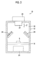
- Fig. 2 is a schematic sectional view showing the internal configuration of an imaging device of this embodiment
- Fig. 3 is a schematic block diagram showing the imaging system 1 of this embodiment.
- the imaging system 1 of this embodiment includes an imaging device body 10 and an imaging control device 100.
- the imaging device body 10 includes a housing 12 which has an opening/closing door 14, a stage 16 on which a subject S is placed, an imaging unit 20, a lens unit 22, an epi-illumination light source unit 24, a transmission light source unit 26, and a subject observation monitor 50.
- the epi-illumination light source unit 24 or the transmission light source unit 26 corresponds to a light source unit of the invention.
- the housing 12 has a hollow portion 18 formed in a substantially rectangular parallelepiped, and is provided with the stage 16 on which the subject S is placed.
- the opening/closing door 14 shown in Fig. 1 is openably attached to the housing 12, and the user opens the opening/closing door 14, places the subject S on the stage 16, and then closes the opening/closing door 14, thereby housing the subject S in the housing 12.
- the housing 12 is constituted of a black box in which external light does not enter the hollow portion 18.
- the stage 16 is formed of a material which transmits light from the transmission light source unit 26.
- a fitting portion 13a which is fitted into a hole 13b formed on the housing body side.
- An open/closed state detection unit 13 (see Fig. 3 ) which detects whether or not the fitting portion 13a is fitted is provided in the hole 13b.
- the open/closed state detection unit 13 detects the open/closed state of the opening/closing door 14 by detecting whether or not the fitting portion 13a is fitted into the hole 13b.
- a micro switch, an optical sensor, or the like is available.
- the open/closed state detection unit 13 of this embodiment corresponds to an open state detection unit of the invention.
- the imaging unit 20 is fixed to the upper surface of the housing 12, includes, for example, an imaging element 21, such as a complementary metal-oxide semiconductor (CMOS) image sensor, and detects light reflected from the subject S, light emitted from the subject S, or light transmitted through the subject S to generate an image signal.
- CMOS complementary metal-oxide semiconductor
- the image signal generated in the imaging unit 20 is subjected to, for example, amplification processing and then output to the imaging control device 100.
- the lens unit 22 is attached to the imaging unit 20.
- the lens unit 22 includes, for example, a plurality of lenses, and the lenses are provided so as to be movable in a direction of an arrow Z to focus on the subject S.
- the lens unit 22 includes, for example, optical elements, such as a diaphragm and an excitation light cut filter, and adjusts the amount or the wavelength of light to be detected.
- the epi-illumination light source unit 24 and the transmission light source unit 26 respectively have, for example, an excitation light source for fluorescent imaging and a white light source, and the light sources are switched under the control of the imaging control device 100 as necessary.
- the subject S in a case of performing imaging for detecting fluorescence emitted from the subject S fluorescence-labeled, the subject S is irradiated with excitation light from the epi-illumination light source unit 24 or the transmission light source unit 26, in a case of performing imaging for detecting reflected light from the subject S, the subject S is irradiated with white light from the epi-illumination light source unit 24, and in a case of performing imaging for detecting transmitted light transmitted through the subject S, the subject S is irradiated with white light from the transmission light source unit 26.
- the subject observation monitor 50 displays a status on the stage 16 imaged by a small camera (not shown) provided in the upper portion of the housing 12. With this, it is possible to confirm the position of the subject S placed on the stage 16 or the height of the stage 16, and to adjust the position of the subject S or the height of the stage 16 such that the subject S is placed suitably for imaging.
- the imaging control device 100 is constituted of, for example, a computer, and includes a control device body 102, an input unit 104, and a display unit 106.
- the imaging control device 100 controls the operations of the imaging unit 20, the epi-illumination light source unit 24, and the transmission light source unit 26 of the imaging device body 10, and the imaging device body 10 images the subject S under the control of the imaging control device 100.
- the imaging unit 20 and the open/closed state detection unit 13 in the imaging device body 10 a reading control unit 111 and a display control unit 112 in the imaging control device 100, and an abnormality detection unit 113 constitute an imaging device of the invention.
- the display control unit 112 corresponds to an output unit and a notification unit of the invention.
- the control device body 102 includes an image processing unit 108, a control unit 110, an abnormality detection unit 113, a temporary storage unit 114, and a continuous storage unit 115.
- the temporary storage unit 114 corresponds to a storage unit of the invention.
- the control unit 110 includes, for example, a central processing unit (CPU), a read only memory (ROM), and the like.
- the control unit 110 integrally controls the operations of the respective units in the imaging device body 10 and the imaging control device 100.
- the control unit 110 includes the reading control unit 111 and the display control unit 112.
- the reading control unit 111 reads and controls the image signal from the imaging element 21 in the imaging unit 20.
- the reading control unit 111 of the embodiment reads an image signal of an observation image from the imaging element 21 when an exposure time set in advance has elapsed, and performs nondestructive reading of the image signal at a given constant time interval for the exposure time (during imaging of the observation image).
- Nondestructive reading refers to a method which, when reading the image signal from the imaging element 21, reads the image signal while maintaining the storage state without emptying electric charge stored in each photoelectric conversion element constituting the imaging element 21. That is, since reset processing is not performed when reading the image signal, it is possible to read the image signal any number of times in the middle of storing electric charge.
- the reading control unit can consecutively perform nondestructive reading of the image signal multiple times, and for example, performs nondestructive reading about two times to 12 times.
- the reading control unit can perform nondestructive reading of the image signal at a given constant time interval set in advance, and for example, performs reading at an interval of, for example, 0.1 seconds to 60 minutes.
- the continuous storage unit 115 stores the image signal of the observation image.
- a nonvolatile memory such as a flash memory
- the continuous storage unit 115 can store the image signal acquired by nondestructive reading in response to a request from the user.
- the temporary storage unit 114 stores the image signal acquired by nondestructive reading.
- a volatile memory such as a synchronous dynamic random access memory (SDRAM)
- SDRAM synchronous dynamic random access memory
- the temporary storage unit 114 corresponds to a storage unit of the invention.
- the image processing unit 108 receives the image signals read from the continuous storage unit 115 and the temporary storage unit 114 as input and subjects the read image signals to necessary signal processing.
- the signal processing includes, for example, dark current correction processing, sharpness processing, and the like.
- the dark current correction processing is processing for subtracting a dark image signal stored in advance from an image signal acquired by imaging.
- the display control unit 112 displays the observation image on the display unit 106 based on the image signal subjected to the signal processing in the image processing unit 108.
- the display control unit 112 reads the nondestructively read image signal stored in the temporary storage unit 114 in a case where the abnormality detection unit 113 detects the occurrence of an abnormal state during imaging, and displays a confirmation image on the display unit 106 based on the image signal subjected to the signal processing in the image processing unit 108.
- the display control unit 112 displays a warning, such as a message informing the user of the effect on the display unit 106.
- a warning such as a message informing the user of the effect on the display unit 106.
- an index such as a mark, may be displayed.
- a lamp may be turned on or sound may be made to give notification to the user.
- the abnormality detection unit 113 detects the occurrence of the abnormal state during imaging of the subject S. Specifically, in a case where the open/closed state detection unit 13 detects that the opening/closing door 14 is opened during imaging of the observation image, the abnormality detection unit 113 of this embodiment receives the detection signal and detects the occurrence of the abnormal state during imaging. In a case where the abnormality detection unit 113 detects the occurrence of the abnormal state during imaging, as described above, the display control unit 112 reads the nondestructively read image signal most recently stored in the temporary storage unit 114, the image signal is subjected to the signal processing in the image processing unit 108, and then, a confirmation image is displayed on the display unit 106 based on the image signal subjected to the signal processing.
- the display unit 106 comprises, for example, a display device, such as a cathode ray tube (CRT) display or a liquid crystal display, and as described above, displays the observation image and the confirmation image, or displays the warning message.
- the display unit 106 displays a setting screen for performing various settings in or giving instructions to the respective units of the imaging device body 10.
- the input unit 104 comprises a mouse, a keyboard, and the like.
- the input unit 104 receives various setting inputs of the respective units in the imaging device body 10.
- the input unit 104 receives selection of whether or not to store the nondestructively read image signal read from the temporary storage unit 114 in the continuous storage unit 115.
- the input unit 104 of this embodiment corresponds to a selection reception unit of the invention.
- the imaging system 1 of this embodiment has the above configuration, thereby performing imaging by four imaging methods according to the type of subject S or the purpose of imaging.
- the four imaging methods include an imaging method (hereinafter, referred to as a first imaging method) which detects chemoluminescence emitted from the subject S, an imaging method (hereinafter, referred to as a second imaging method) which detects fluorescence emitted from the subject S, an imaging method (hereinafter, referred to as a third imaging method) which detects reflected light reflected from the subject S, and an imaging method (hereinafter, referred to as a fourth imaging method) which detects transmitted light transmitted through the subject S.
- a first imaging method which detects chemoluminescence emitted from the subject S
- an imaging method hereinafter, referred to as a second imaging method
- an imaging method hereinafter, referred to as a third imaging method
- a fourth imaging method which detects transmitted light transmitted through the subject S.
- the first imaging method a phenomenon (chemoluminescence or chemiluminescence) in which, when a subject molecule excited by a chemical reaction is returned to a ground state, energy is discharged as light is used.
- chemoluminescence or chemiluminescence a phenomenon in which, when a subject molecule excited by a chemical reaction is returned to a ground state, energy is discharged as light.
- an imaging target substance in a subject is labeled by a labeling substance which generates chemoluminescence when coming into contact with a chemoluminescence substrate, and thereafter, the chemoluminescence substrate is brought into contact with the labeling substance, whereby chemoluminescence can be generated.
- light irradiation from the epi-illumination light source unit 24 and the transmission light source unit 26 is not performed.
- excitation light is irradiated from the epi-illumination light source unit 24 or the transmission light source unit 26, and fluorescence from a fluorescence substance labeling an imaging target substance in a subject is detected.
- a gel support containing a deoxyribonucleic acid (DNA) fragment fluorescence-labeled and separated by electrophoresis is considered. If this imaging system 1 is used, the distribution of the DNA fragment in the gel support can be imaged and evaluated.
- the third imaging method for example, white light is irradiated as illumination light from the epi-illumination light source unit 24, and reflected light of illumination light from the subject S is detected. With this, it is possible to obtain a digital image by photoelectrically reading a reflective original, such as a photograph.
- white light is irradiated as illumination light from the transmission light source unit 26, and transmitted light of illumination light transmitted through the subject S is detected. With this, it is possible to obtain a digital image by photoelectrically reading a transmissive original, such as a film.
- an imaging start instruction is input by the user using the input unit 104, and imaging by the imaging unit 20 is started. Specifically, exposure of the imaging element 21 of the imaging unit 20 is started (S10).
- an image signal is read from the imaging element 21 at a given constant time interval (for example, an interval of one second) by nondestructive reading (S12), and the image signal is sequentially stored in the temporary storage unit 114 (S 14).
- the open/closed state detection unit 13 detects this state, the abnormality detection unit 113 receives the detection signal, and the abnormality detection unit 113 detects the occurrence of an abnormal state during imaging (S 18).
- the display control unit 112 displays a warning message on the display unit 106 (S20), and the control unit 110 stops imaging (S22).
- the display control unit 112 reads the nondestructively read image signal most recently stored in the temporary storage unit 114 (S24).
- the nondestructively read image signal read from the temporary storage unit 114 is input to the image processing unit 108 and is subjected to signal processing in the image processing unit 108, and then, the display control unit 112 displays a confirmation image on the display unit 106 based on the image signal subjected to the signal processing (S26).
- a selection screen of whether or not to store the nondestructively read image signal in the continuous storage unit 115 is displayed on the display unit 106, and in a case where the user selects to store the image signal in the continuous storage unit 115 using the input unit 104 (S28, YES), the nondestructively read image signal is stored in the continuous storage unit 115 (S30). In a case where the user selects not to store the image signal in the continuous storage unit 115 (S28, NO), the nondestructively read image signal is not stored in the continuous storage unit 115, and the processing ends. In this way, the user selects whether or not to store the nondestructively read image signal in the continuous storage unit 115, whereby only a necessary image signal can be stored in the continuous storage unit 115.
- the reading control unit 111 reads the image signal from the imaging element 21 by destructive reading, and the image signal is stored in the continuous storage unit 115 (S34).
- Destructive reading refers to a reading method which, when reading the image signal from the photoelectric conversion element of the imaging element 21, performs reset processing for emptying electric charge stored in the photoelectric conversion element.
- the display control unit 112 reads the destructively read image signal stored in the continuous storage unit 115, the image signal is subjected to signal processing in the image processing unit 108, and then, the display control unit 112 displays an observation image on the display unit 106 based on the image signal subjected to the signal processing (S36).
- nondestructive reading of the image signal from the imaging element 21 is performed during imaging of the subject S, and the nondestructively read image signal is stored.
- the stored image signal is read and output; thus, even in a case where the user erroneously opens the door of the housing 12 during imaging, it is possible to allow the user to confirm the image captured immediately before.
- the imaging system 2 of the second embodiment detects the occurrence of the abnormal state during imaging in a case where abnormality of the imaging element 21 is detected. Specifically, the imaging system 2 of the second embodiment detects temperature abnormality of the imaging element 21. This is because, if the temperature of the imaging element 21 changes, a dark current level changes and has magnitude different from the dark image signal for use when performing the dark current correction processing described above, and appropriate dark current correction processing cannot be performed.
- other configurations are the same as those in the imaging system 1 of the first embodiment.
- Fig. 5 is a block diagram showing the schematic configuration of the imaging system 2 of the second embodiment.
- an imaging device body 10 of the imaging system 2 of the second embodiment is provided with an imaging element abnormality detection unit 27 which detects abnormality of the imaging element 21.
- the imaging element abnormality detection unit 27 of this embodiment comprises a temperature sensor which detects the temperature of the imaging element 21, and detects abnormality of the imaging element 21 in a case where the temperature detected by the temperature sensor is outside a range set in advance.
- the imaging element abnormality detection unit 27 may directly detect the temperature of the imaging element 21, or may detect the temperature of outside air near the imaging element 21 to indirectly the temperature of the imaging element 21.
- an imaging start instruction is input by the user using the input unit 104, and imaging by the imaging unit 20 is started (S40).
- an image signal is read from the imaging element 21 at a given constant time interval by nondestructive reading (S42), and the image signal is sequentially stored in the temporary storage unit 114 (S44).
- the imaging element abnormality detection unit 27 detects this state, the abnormality detection unit 113 receives the detection signal, and the abnormality detection unit 113 detects the occurrence of the abnormal state during imaging (S48).
- the first threshold range is set to, for example, -25°C ⁇ 0.5°C.
- the display control unit 112 displays a warning message on the display unit 106 (S50).
- the second threshold range is set to, for example, -25°C ⁇ 1°C.
- the display control unit 112 reads the nondestructively read image signal most recently stored in the temporary storage unit 114 (S58).
- the nondestructively read image signal read from the temporary storage unit 114 is input to the image processing unit 108 and is subjected to signal processing in the image processing unit 108, and then, the display control unit 112 displays a confirmation image on the display unit 106 based on the image signal subjected to the signal processing (S60).
- a selection screen of whether or not to store the nondestructively read image signal in the continuous storage unit 115 is displayed on the display unit 106, and in a case where the user selects to store the image signal in the continuous storage unit 115 (S62, YES), the nondestructively read image signal is stored in the continuous storage unit 115 (S64). In a case where the user selects not to store the image signal in the continuous storage unit 115 (S62, NO), the nondestructively read image signal is not stored in the continuous storage unit 115, and the processing ends.
- the reading control unit 111 reads the image signal from the imaging element 21 by destructive reading, and the image signal is stored in the continuous storage unit 115 (S68).
- the display control unit 112 reads the destructively read image signal stored in the continuous storage unit 115, the image signal is subjected to signal processing in the image processing unit 108, and then, the display control unit 112 displays an observation image on the display unit 106 based on the image signal subjected to the signal processing (S70).
- the imaging system 2 of the second embodiment described above even in a case where abnormality occurs in the imaging element 21 during imaging, it is possible to subject an image captured immediately before to appropriate dark current correction processing, and to allow the user to confirm the image.
- an imaging system 3 using a third embodiment of an imaging device and method of the invention will be described.
- the abnormality detection unit 113 detects the occurrence of the abnormal state during imaging in a case where abnormality of the imaging element 21 is detected
- the imaging system 3 of the third embodiment detects the occurrence of the abnormal state during imaging in a case where abnormality of the light source is detected.
- other configurations are the same as those in the imaging system 1 of the first embodiment.
- Fig. 7 is a block diagram showing the schematic configuration of the imaging system 3 of the third embodiment.
- an imaging device body 10 of the imaging system 3 of the third embodiment is provided with a light source abnormality detection unit 28 which detects abnormality of the epi-illumination light source unit 24 and the transmission light source unit 26.
- the light source abnormality detection unit 28 of this embodiment detects disconnection or short-circuiting in the epi-illumination light source unit 24 and the transmission light source unit 26.
- a disconnection and short-circuiting detection function of an IC which drives and controls the light sources may be used, or a voltage or the like applied to the epi-illumination light source unit 24 and the transmission light source unit 26 may be monitored.
- an imaging start instruction is input by the user using the input unit 104, and imaging by the imaging unit 20 is started (S80).
- an image signal is read from the imaging element 21 at a given constant time interval by nondestructive reading (S82), and the image signal is sequentially stored in the temporary storage unit 114 (S84).
- the light source abnormality detection unit 28 detects this state, the abnormality detection unit 113 receives the detection signal, and the abnormality detection unit 113 detects the occurrence of the abnormal state during imaging (S88).
- the display control unit 112 displays a warning message on the display unit 106 (S90), and the control unit 110 stops imaging (S92).
- the display control unit 112 reads the nondestructively read image signal most recently stored in the temporary storage unit 114 (S94).
- the nondestructively read image signal read from the temporary storage unit 114 is input to the image processing unit 108 and is subjected to signal processing in the image processing unit 108, and then, the display control unit 112 displays a confirmation image on the display unit 106 based on the image signal subjected to the signal processing (S96).
- a selection screen of whether or not to store the nondestructively read image signal in the continuous storage unit 115 is displayed on the display unit 106, and in a case where the user selects to store the image signal in the continuous storage unit 115 (S98, YES), the nondestructively read image signal is stored in the continuous storage unit 115 (S100). In a case where the user selects not to store the image signal in the continuous storage unit 115 (S98, NO), the nondestructively read image signal is not stored in the continuous storage unit 115, and the processing ends.
- the reading control unit 111 reads the image signal from the imaging element 21 by destructive reading, and the image signal is stored in the continuous storage unit 115 (S104).
- Destructive reading refers to a reading method which, when reading the image signal from the photoelectric conversion element of the imaging element 21, performs reset processing for emptying electric charge stored in the photoelectric conversion element.
- the display control unit 112 reads the destructively read image signal stored in the continuous storage unit 115, the image signal is subjected to signal processing in the image processing unit 108, and then, the display control unit 112 displays an observation image on the display unit 106 based on the image signal subjected to the signal processing (S106).
- the imaging system 3 of the third embodiment described above even in a case where abnormality occurs in the light source during imaging, it is possible to allow the user to confirm an image captured immediately before.
- the imaging system 1 of the first embodiment described above detects that the opening/closing door 14 is opened during imaging
- the imaging system 2 of the second embodiment detects the occurrence of abnormality in the imaging element 21
- the imaging system 3 of the third embodiment detects the occurrence of abnormality in the light source, all of these abnormalities may be detected.
- the abnormality detection unit 113 may detect abnormal states in steps and may be operated according to the degree of abnormality.
- the display control unit 112 displays a warning message and the control unit 110 stops imaging. In this way, the abnormal states are detected in steps, whereby it is possible to prevent imaging from being wastefully stopped.
Landscapes
- Engineering & Computer Science (AREA)
- Multimedia (AREA)
- Signal Processing (AREA)
- Physics & Mathematics (AREA)
- General Physics & Mathematics (AREA)
- Health & Medical Sciences (AREA)
- Biomedical Technology (AREA)
- General Health & Medical Sciences (AREA)
- Studio Devices (AREA)
Abstract
Description
- The present invention relates to an imaging device and an imaging method which image light emitted from a subject with an imaging element.
- Hitherto, an imaging system which has a subject placed inside a housing, irradiates the subject with light using a light source provided in the housing to image the subject has been used in various fields.
- In such an imaging system, an imaging method is primarily switched depending on the type of subject, and for example, an imaging system which images chemoluminescence, fluorescence, or reflected light from the subject or transmitted light transmitted through the subject with an imaging element to generate an image has been suggested.
- In the imaging system described above, for example, in a case where a user erroneously open a door of the housing during imaging, since external light enters the housing, external light fogs an image being captured, and the image is invalidated. In a case where abnormality occurs in the imaging element which captures an image, the light source, or the like during imaging, appropriate imaging cannot be performed, and an image is invalidated.
-
JP2004-180317A JP2002-27326A - The invention has been accomplished in consideration of the above-described problem, and an object of the invention is to provide an imaging device and an imaging method capable of allowing a user to confirm an image captured immediately before in a case where the user erroneously opens a door of a housing during imaging or in a case where abnormality occurs in an imaging element, a light source, or the like during imaging.
- An imaging device of the invention comprises an imaging unit which has an imaging element configured to nondestructively read an image signal and performs imaging of a subject using the imaging element, a reading control unit which performs nondestructive reading of the image signal from the imaging element during imaging of the subject, a storage unit which stores the image signal nondestructively read by the reading control unit, an abnormality detection unit which detects the occurrence of an abnormal state during imaging of the subject, and an output unit which reads and outputs the image signal stored in the storage unit in a case where the abnormal state is detected by the abnormality detection unit.
- In the imaging device of the invention, the reading control unit may consecutively perform nondestructive reading of the image signal multiple times.
- In the imaging device of the invention, the reading control unit may perform nondestructive reading of the image signal at a given constant time interval set in advance.
- The imaging device of the invention may further comprise a housing in which the subject is placed and which has an opening/closing door, and an open state detection unit which detects an open state of the opening/closing door, and the abnormality detection unit may detect the occurrence of the abnormal state in a case where the open state of the opening/closing door is detected by the open state detection unit.
- The imaging device of the invention may further comprise an imaging element abnormality detection unit which detects abnormality of the imaging element, and the abnormality detection unit may detect the occurrence of the abnormal state in a case where abnormality of the imaging element is detected by the imaging element abnormality detection unit.
- In the imaging device of the invention, the imaging element abnormality detection unit may detect the temperature of the imaging element and may detect abnormality of the imaging element in a case where the detected temperature is outside a range set in advance.
- The imaging device of the invention may further comprise a light source unit which irradiates the subject with light, and a light source abnormality detection unit which detects abnormality of the light source unit, and the abnormality detection unit may detect the occurrence of the abnormal state in a case where abnormality of the light source unit is detected by the light source abnormality detection unit.
- In the imaging device of the invention, the light source abnormality detection unit may detect abnormality of the light source unit in a case where disconnection or short-circuiting of the light source unit is detected.
- In the imaging device of the invention, the abnormality detection unit may detect abnormal states in steps, and the imaging device may further comprise a notification unit which gives notification of the abnormal state in a case where an abnormal state of a first step is detected, and a control unit which stops the imaging in a case where an abnormal state of a second step having a higher degree of abnormality than the first step is detected. The abnormal state of the first step refers to an abnormal state which does not have a significant effect on an image, and is, for example, a state in which the temperature of the imaging element exceeds a threshold by 0.5°C. The abnormal state of the second step is a state in which abnormality appears in an image visibly, and refers to a case where the temperature of the imaging element exceeds the threshold by 10°C, a case where the light source is disconnected (turned off), or a case where the door is opened during imaging.
- The imaging device of the invention may further comprise a continuous storage unit which has a nonvolatile memory, and a selection reception unit which receives selection of whether or not to store the nondestructively read image signal read from the storage unit in the continuous storage unit, and the nondestructively read image signal may be stored in the continuous storage unit in a case where the selection reception unit selects to store the nondestructively read image signal, and the nondestructively read image signal may not be stored in the continuous storage unit in a case where the selection reception unit selects not to store the nondestructively read image signal.
- As the imaging element, a complementary metal-oxide semiconductor (CMOS) image sensor may be used.
- An imaging method of the invention which performs imaging of a subject using an imaging element configured to nondestructively read an image signal comprises performing nondestructive reading of the image signal from the imaging element during imaging of the subject, storing the nondestructively read image signal, and reading and outputting the stored image signal in a case where the occurrence of an abnormal state during imaging of the subject is detected.
- According to the imaging device and the imaging method of the invention, when performing imaging of the subject using the imaging element capable of nondestructively reading the image signal, nondestructive reading of the image signal from the imaging element is performed during imaging of the subject, and the nondestructive read image signal is stored. In a case where the abnormal state occurs during imaging of the subject, the stored image signal is read and output; therefore, as described above, even in a case where the user erroneously opens the door of the housing during imaging or a case where abnormality occurs in the imaging element which captures an image, the light source, or the like during imaging, it is possible to allow the user to confirm an image captured immediately before.
-
-
Fig. 1 is a schematic perspective view of an imaging system using an embodiment of an imaging device of the invention. -
Fig. 2 is a schematic sectional view showing the internal configuration of the embodiment of the imaging device of the invention. -
Fig. 3 is a schematic block diagram of an imaging system using a first embodiment of an imaging device of the invention. -
Fig. 4 is a flowchart illustrating the action of the imaging system using the first embodiment of the imaging device of the invention. -
Fig. 5 is a schematic block diagram of an imaging system using a second embodiment of an imaging device of the invention. -
Fig. 6 is a flowchart illustrating the action of the imaging system using the second embodiment of the imaging device of the invention. -
Fig. 7 is a schematic block diagram of an imaging system using a third embodiment of an imaging device of the invention. -
Fig. 8 is a flowchart illustrating the action of the imaging system using the third embodiment of the imaging device of the invention. - Hereinafter, an
imaging system 1 using a first embodiment of an imaging device and method of the invention will be described in detail referring to the drawings. Theimaging system 1 of this embodiment has a feature in processing in a case where an abnormal state occurs during imaging, and first, the overall configuration of theimaging system 1 will be described. -
Fig. 1 is a schematic perspective view showing theimaging system 1 of this embodiment,Fig. 2 is a schematic sectional view showing the internal configuration of an imaging device of this embodiment, andFig. 3 is a schematic block diagram showing theimaging system 1 of this embodiment. - As shown in
Figs. 1 and2 , theimaging system 1 of this embodiment includes animaging device body 10 and animaging control device 100. - The
imaging device body 10 includes ahousing 12 which has an opening/closingdoor 14, astage 16 on which a subject S is placed, animaging unit 20, alens unit 22, an epi-illuminationlight source unit 24, a transmissionlight source unit 26, and asubject observation monitor 50. In this embodiment, the epi-illuminationlight source unit 24 or the transmissionlight source unit 26 corresponds to a light source unit of the invention. - The
housing 12 has ahollow portion 18 formed in a substantially rectangular parallelepiped, and is provided with thestage 16 on which the subject S is placed. The opening/closing door 14 shown inFig. 1 is openably attached to thehousing 12, and the user opens the opening/closingdoor 14, places the subject S on thestage 16, and then closes the opening/closingdoor 14, thereby housing the subject S in thehousing 12. Thehousing 12 is constituted of a black box in which external light does not enter thehollow portion 18. Thestage 16 is formed of a material which transmits light from the transmissionlight source unit 26. - In a surface of the opening/closing
door 14 on thehollow portion 18 side, when the opening/closing door 14 is closed, afitting portion 13a which is fitted into ahole 13b formed on the housing body side. An open/closed state detection unit 13 (seeFig. 3 ) which detects whether or not thefitting portion 13a is fitted is provided in thehole 13b. As described above, the open/closedstate detection unit 13 detects the open/closed state of the opening/closing door 14 by detecting whether or not thefitting portion 13a is fitted into thehole 13b. As the open/closedstate detection unit 13, a micro switch, an optical sensor, or the like is available. The open/closedstate detection unit 13 of this embodiment corresponds to an open state detection unit of the invention. - The
imaging unit 20 is fixed to the upper surface of thehousing 12, includes, for example, animaging element 21, such as a complementary metal-oxide semiconductor (CMOS) image sensor, and detects light reflected from the subject S, light emitted from the subject S, or light transmitted through the subject S to generate an image signal. The image signal generated in theimaging unit 20 is subjected to, for example, amplification processing and then output to theimaging control device 100. - The
lens unit 22 is attached to theimaging unit 20. Thelens unit 22 includes, for example, a plurality of lenses, and the lenses are provided so as to be movable in a direction of an arrow Z to focus on the subject S. Thelens unit 22 includes, for example, optical elements, such as a diaphragm and an excitation light cut filter, and adjusts the amount or the wavelength of light to be detected. - The epi-illumination
light source unit 24 and the transmissionlight source unit 26 respectively have, for example, an excitation light source for fluorescent imaging and a white light source, and the light sources are switched under the control of theimaging control device 100 as necessary. For example, in a case of performing imaging for detecting fluorescence emitted from the subject S fluorescence-labeled, the subject S is irradiated with excitation light from the epi-illuminationlight source unit 24 or the transmissionlight source unit 26, in a case of performing imaging for detecting reflected light from the subject S, the subject S is irradiated with white light from the epi-illuminationlight source unit 24, and in a case of performing imaging for detecting transmitted light transmitted through the subject S, the subject S is irradiated with white light from the transmissionlight source unit 26. - The
subject observation monitor 50 displays a status on thestage 16 imaged by a small camera (not shown) provided in the upper portion of thehousing 12. With this, it is possible to confirm the position of the subject S placed on thestage 16 or the height of thestage 16, and to adjust the position of the subject S or the height of thestage 16 such that the subject S is placed suitably for imaging. - The
imaging control device 100 is constituted of, for example, a computer, and includes acontrol device body 102, aninput unit 104, and adisplay unit 106. Theimaging control device 100 controls the operations of theimaging unit 20, the epi-illuminationlight source unit 24, and the transmissionlight source unit 26 of theimaging device body 10, and theimaging device body 10 images the subject S under the control of theimaging control device 100. In this embodiment, theimaging unit 20 and the open/closedstate detection unit 13 in theimaging device body 10, areading control unit 111 and adisplay control unit 112 in theimaging control device 100, and anabnormality detection unit 113 constitute an imaging device of the invention. In this embodiment, thedisplay control unit 112 corresponds to an output unit and a notification unit of the invention. - As shown in
Fig. 3 , thecontrol device body 102 includes animage processing unit 108, acontrol unit 110, anabnormality detection unit 113, atemporary storage unit 114, and acontinuous storage unit 115. In this embodiment, thetemporary storage unit 114 corresponds to a storage unit of the invention. - The
control unit 110 includes, for example, a central processing unit (CPU), a read only memory (ROM), and the like. Thecontrol unit 110 integrally controls the operations of the respective units in theimaging device body 10 and theimaging control device 100. - The
control unit 110 includes thereading control unit 111 and thedisplay control unit 112. Thereading control unit 111 reads and controls the image signal from theimaging element 21 in theimaging unit 20. - The
reading control unit 111 of the embodiment reads an image signal of an observation image from theimaging element 21 when an exposure time set in advance has elapsed, and performs nondestructive reading of the image signal at a given constant time interval for the exposure time (during imaging of the observation image). Nondestructive reading refers to a method which, when reading the image signal from theimaging element 21, reads the image signal while maintaining the storage state without emptying electric charge stored in each photoelectric conversion element constituting theimaging element 21. That is, since reset processing is not performed when reading the image signal, it is possible to read the image signal any number of times in the middle of storing electric charge. The reading control unit can consecutively perform nondestructive reading of the image signal multiple times, and for example, performs nondestructive reading about two times to 12 times. The reading control unit can perform nondestructive reading of the image signal at a given constant time interval set in advance, and for example, performs reading at an interval of, for example, 0.1 seconds to 60 minutes. - However, the invention is not limited to the above.
- The
continuous storage unit 115 stores the image signal of the observation image. As thecontinuous storage unit 115, for example, a nonvolatile memory, such as a flash memory, is available. Thecontinuous storage unit 115 can store the image signal acquired by nondestructive reading in response to a request from the user. - The
temporary storage unit 114 stores the image signal acquired by nondestructive reading. As thetemporary storage unit 114, for example, a volatile memory, such as a synchronous dynamic random access memory (SDRAM), is available. In the embodiment, thetemporary storage unit 114 corresponds to a storage unit of the invention. - The
image processing unit 108 receives the image signals read from thecontinuous storage unit 115 and thetemporary storage unit 114 as input and subjects the read image signals to necessary signal processing. The signal processing includes, for example, dark current correction processing, sharpness processing, and the like. The dark current correction processing is processing for subtracting a dark image signal stored in advance from an image signal acquired by imaging. - The
display control unit 112 displays the observation image on thedisplay unit 106 based on the image signal subjected to the signal processing in theimage processing unit 108. Thedisplay control unit 112 reads the nondestructively read image signal stored in thetemporary storage unit 114 in a case where theabnormality detection unit 113 detects the occurrence of an abnormal state during imaging, and displays a confirmation image on thedisplay unit 106 based on the image signal subjected to the signal processing in theimage processing unit 108. - In a case where the
abnormality detection unit 113 detects the occurrence of the abnormal state during imaging, thedisplay control unit 112 displays a warning, such as a message informing the user of the effect on thedisplay unit 106. Instead of a message, an index, such as a mark, may be displayed. In this embodiment, although a message or the like is displayed to give the user a warning, the invention is not limited thereto, a lamp may be turned on or sound may be made to give notification to the user. - The
abnormality detection unit 113 detects the occurrence of the abnormal state during imaging of the subject S. Specifically, in a case where the open/closedstate detection unit 13 detects that the opening/closingdoor 14 is opened during imaging of the observation image, theabnormality detection unit 113 of this embodiment receives the detection signal and detects the occurrence of the abnormal state during imaging. In a case where theabnormality detection unit 113 detects the occurrence of the abnormal state during imaging, as described above, thedisplay control unit 112 reads the nondestructively read image signal most recently stored in thetemporary storage unit 114, the image signal is subjected to the signal processing in theimage processing unit 108, and then, a confirmation image is displayed on thedisplay unit 106 based on the image signal subjected to the signal processing. - The
display unit 106 comprises, for example, a display device, such as a cathode ray tube (CRT) display or a liquid crystal display, and as described above, displays the observation image and the confirmation image, or displays the warning message. Thedisplay unit 106 displays a setting screen for performing various settings in or giving instructions to the respective units of theimaging device body 10. - The
input unit 104 comprises a mouse, a keyboard, and the like. Theinput unit 104 receives various setting inputs of the respective units in theimaging device body 10. Theinput unit 104 receives selection of whether or not to store the nondestructively read image signal read from thetemporary storage unit 114 in thecontinuous storage unit 115. Theinput unit 104 of this embodiment corresponds to a selection reception unit of the invention. - The
imaging system 1 of this embodiment has the above configuration, thereby performing imaging by four imaging methods according to the type of subject S or the purpose of imaging. The four imaging methods include an imaging method (hereinafter, referred to as a first imaging method) which detects chemoluminescence emitted from the subject S, an imaging method (hereinafter, referred to as a second imaging method) which detects fluorescence emitted from the subject S, an imaging method (hereinafter, referred to as a third imaging method) which detects reflected light reflected from the subject S, and an imaging method (hereinafter, referred to as a fourth imaging method) which detects transmitted light transmitted through the subject S. - In the first imaging method, a phenomenon (chemoluminescence or chemiluminescence) in which, when a subject molecule excited by a chemical reaction is returned to a ground state, energy is discharged as light is used. With this, for example, it is possible to perform genetic analysis, inspection and research of biological tissues relating to diseases and aging, deterioration evaluation of organic compounds and polymer compounds, and the like. For example, an imaging target substance in a subject is labeled by a labeling substance which generates chemoluminescence when coming into contact with a chemoluminescence substrate, and thereafter, the chemoluminescence substrate is brought into contact with the labeling substance, whereby chemoluminescence can be generated. In the first imaging method, light irradiation from the epi-illumination
light source unit 24 and the transmissionlight source unit 26 is not performed. - In the second imaging method, excitation light is irradiated from the epi-illumination
light source unit 24 or the transmissionlight source unit 26, and fluorescence from a fluorescence substance labeling an imaging target substance in a subject is detected. As the subject S of the second imaging method, for example, a gel support containing a deoxyribonucleic acid (DNA) fragment fluorescence-labeled and separated by electrophoresis is considered. If thisimaging system 1 is used, the distribution of the DNA fragment in the gel support can be imaged and evaluated. - In the third imaging method, for example, white light is irradiated as illumination light from the epi-illumination
light source unit 24, and reflected light of illumination light from the subject S is detected. With this, it is possible to obtain a digital image by photoelectrically reading a reflective original, such as a photograph. In the fourth imaging method, white light is irradiated as illumination light from the transmissionlight source unit 26, and transmitted light of illumination light transmitted through the subject S is detected. With this, it is possible to obtain a digital image by photoelectrically reading a transmissive original, such as a film. - Next, the action of the
imaging system 1 of this embodiment will be described referring to the flowchart shown inFig. 4 . - First, after the subject S is placed on the
stage 16 of theimaging device body 10, an imaging start instruction is input by the user using theinput unit 104, and imaging by theimaging unit 20 is started. Specifically, exposure of theimaging element 21 of theimaging unit 20 is started (S10). - After imaging is started, an image signal is read from the
imaging element 21 at a given constant time interval (for example, an interval of one second) by nondestructive reading (S12), and the image signal is sequentially stored in the temporary storage unit 114 (S 14). - In a case where the opening/closing
door 14 is erroneously opened by the user during imaging of the subject S (S16, YES), the open/closedstate detection unit 13 detects this state, theabnormality detection unit 113 receives the detection signal, and theabnormality detection unit 113 detects the occurrence of an abnormal state during imaging (S 18). - In a case where the
abnormality detection unit 113 detects the occurrence of the abnormal state during imaging, thedisplay control unit 112 displays a warning message on the display unit 106 (S20), and thecontrol unit 110 stops imaging (S22). - Next, the
display control unit 112 reads the nondestructively read image signal most recently stored in the temporary storage unit 114 (S24). - The nondestructively read image signal read from the
temporary storage unit 114 is input to theimage processing unit 108 and is subjected to signal processing in theimage processing unit 108, and then, thedisplay control unit 112 displays a confirmation image on thedisplay unit 106 based on the image signal subjected to the signal processing (S26). - A selection screen of whether or not to store the nondestructively read image signal in the
continuous storage unit 115 is displayed on thedisplay unit 106, and in a case where the user selects to store the image signal in thecontinuous storage unit 115 using the input unit 104 (S28, YES), the nondestructively read image signal is stored in the continuous storage unit 115 (S30). In a case where the user selects not to store the image signal in the continuous storage unit 115 (S28, NO), the nondestructively read image signal is not stored in thecontinuous storage unit 115, and the processing ends. In this way, the user selects whether or not to store the nondestructively read image signal in thecontinuous storage unit 115, whereby only a necessary image signal can be stored in thecontinuous storage unit 115. - In a case where the door is not opened during imaging and an imaging exposure time set in advance has elapsed (S32, YES), the
reading control unit 111 reads the image signal from theimaging element 21 by destructive reading, and the image signal is stored in the continuous storage unit 115 (S34). Destructive reading refers to a reading method which, when reading the image signal from the photoelectric conversion element of theimaging element 21, performs reset processing for emptying electric charge stored in the photoelectric conversion element. - The
display control unit 112 reads the destructively read image signal stored in thecontinuous storage unit 115, the image signal is subjected to signal processing in theimage processing unit 108, and then, thedisplay control unit 112 displays an observation image on thedisplay unit 106 based on the image signal subjected to the signal processing (S36). - According to the
imaging system 1 of the first embodiment described above, nondestructive reading of the image signal from theimaging element 21 is performed during imaging of the subject S, and the nondestructively read image signal is stored. In a case where the occurrence of an abnormal state during imaging of the subject S is detected, the stored image signal is read and output; thus, even in a case where the user erroneously opens the door of thehousing 12 during imaging, it is possible to allow the user to confirm the image captured immediately before. - Next, an
imaging system 2 using a second embodiment of an imaging device and method of the invention will be described. In theimaging system 1 of the first embodiment, although theabnormality detection unit 113 detects the occurrence of the abnormal state during imaging in a case where the opening/closingdoor 14 is erroneously opened during imaging, theimaging system 2 of the second embodiment detects the occurrence of the abnormal state during imaging in a case where abnormality of theimaging element 21 is detected. Specifically, theimaging system 2 of the second embodiment detects temperature abnormality of theimaging element 21. This is because, if the temperature of theimaging element 21 changes, a dark current level changes and has magnitude different from the dark image signal for use when performing the dark current correction processing described above, and appropriate dark current correction processing cannot be performed. In theimaging system 2 of the second embodiment, other configurations are the same as those in theimaging system 1 of the first embodiment. -
Fig. 5 is a block diagram showing the schematic configuration of theimaging system 2 of the second embodiment. As shown inFig. 5 , animaging device body 10 of theimaging system 2 of the second embodiment is provided with an imaging elementabnormality detection unit 27 which detects abnormality of theimaging element 21. Specifically, the imaging elementabnormality detection unit 27 of this embodiment comprises a temperature sensor which detects the temperature of theimaging element 21, and detects abnormality of theimaging element 21 in a case where the temperature detected by the temperature sensor is outside a range set in advance. The imaging elementabnormality detection unit 27 may directly detect the temperature of theimaging element 21, or may detect the temperature of outside air near theimaging element 21 to indirectly the temperature of theimaging element 21. - Next, the action of the
imaging system 2 of this embodiment will be described referring to the flowchart shown inFig. 6 . - First, after the subject S is placed on the
stage 16 of theimaging device body 10, an imaging start instruction is input by the user using theinput unit 104, and imaging by theimaging unit 20 is started (S40). - After imaging is started, an image signal is read from the
imaging element 21 at a given constant time interval by nondestructive reading (S42), and the image signal is sequentially stored in the temporary storage unit 114 (S44). - In a case where the temperature of the
imaging element 21 is outside a first threshold range during imaging of the subject S (S46, YES), the imaging elementabnormality detection unit 27 detects this state, theabnormality detection unit 113 receives the detection signal, and theabnormality detection unit 113 detects the occurrence of the abnormal state during imaging (S48). The first threshold range is set to, for example, -25°C ± 0.5°C. - As described above, in a case where the temperature of the
imaging element 21 is outside the first threshold range, first, thedisplay control unit 112 displays a warning message on the display unit 106 (S50). - Subsequently, imaging is continued, and in a case where the temperature of the
imaging element 21 continues to change and is outside a second threshold range (S52, YES), thedisplay control unit 112 further displays a warning message on the display unit 106 (S54), and thecontrol unit 110 stops imaging (S56). The second threshold range is set to, for example, -25°C ± 1°C. - Next, the
display control unit 112 reads the nondestructively read image signal most recently stored in the temporary storage unit 114 (S58). - The nondestructively read image signal read from the
temporary storage unit 114 is input to theimage processing unit 108 and is subjected to signal processing in theimage processing unit 108, and then, thedisplay control unit 112 displays a confirmation image on thedisplay unit 106 based on the image signal subjected to the signal processing (S60). - A selection screen of whether or not to store the nondestructively read image signal in the
continuous storage unit 115 is displayed on thedisplay unit 106, and in a case where the user selects to store the image signal in the continuous storage unit 115 (S62, YES), the nondestructively read image signal is stored in the continuous storage unit 115 (S64). In a case where the user selects not to store the image signal in the continuous storage unit 115 (S62, NO), the nondestructively read image signal is not stored in thecontinuous storage unit 115, and the processing ends. - In a case where the temperature of the
imaging element 21 is not outside the first threshold range during imaging (S46, NO) and in a case where the temperature of theimaging element 21 is outside the first threshold range during imaging and is not outside the second threshold range (S52, NO), when an imaging exposure time set in advance has elapsed (S66, YES), thereading control unit 111 reads the image signal from theimaging element 21 by destructive reading, and the image signal is stored in the continuous storage unit 115 (S68). - The
display control unit 112 reads the destructively read image signal stored in thecontinuous storage unit 115, the image signal is subjected to signal processing in theimage processing unit 108, and then, thedisplay control unit 112 displays an observation image on thedisplay unit 106 based on the image signal subjected to the signal processing (S70). - According to the
imaging system 2 of the second embodiment described above, even in a case where abnormality occurs in theimaging element 21 during imaging, it is possible to subject an image captured immediately before to appropriate dark current correction processing, and to allow the user to confirm the image. - Next, an
imaging system 3 using a third embodiment of an imaging device and method of the invention will be described. In theimaging system 2 of the second embodiment, although theabnormality detection unit 113 detects the occurrence of the abnormal state during imaging in a case where abnormality of theimaging element 21 is detected, theimaging system 3 of the third embodiment detects the occurrence of the abnormal state during imaging in a case where abnormality of the light source is detected. In theimaging system 3 of the third embodiment, other configurations are the same as those in theimaging system 1 of the first embodiment. -
Fig. 7 is a block diagram showing the schematic configuration of theimaging system 3 of the third embodiment. As shown inFig. 7 , animaging device body 10 of theimaging system 3 of the third embodiment is provided with a light sourceabnormality detection unit 28 which detects abnormality of the epi-illuminationlight source unit 24 and the transmissionlight source unit 26. Specifically, the light sourceabnormality detection unit 28 of this embodiment detects disconnection or short-circuiting in the epi-illuminationlight source unit 24 and the transmissionlight source unit 26. In regards to disconnection and short-circuiting in the epi-illuminationlight source unit 24 and the transmissionlight source unit 26, for example, a disconnection and short-circuiting detection function of an IC which drives and controls the light sources may be used, or a voltage or the like applied to the epi-illuminationlight source unit 24 and the transmissionlight source unit 26 may be monitored. - Next, the action of the
imaging system 3 of this embodiment will be described referring to the flowchart shown inFig. 8 . - First, after the subject S is placed on the
stage 16 of theimaging device body 10, an imaging start instruction is input by the user using theinput unit 104, and imaging by theimaging unit 20 is started (S80). - After imaging is started, an image signal is read from the
imaging element 21 at a given constant time interval by nondestructive reading (S82), and the image signal is sequentially stored in the temporary storage unit 114 (S84). - In a case where disconnection or short-circuiting of the epi-illumination
light source unit 24 or the transmissionlight source unit 26 occurs during imaging of the subject S (S86, YES), the light sourceabnormality detection unit 28 detects this state, theabnormality detection unit 113 receives the detection signal, and theabnormality detection unit 113 detects the occurrence of the abnormal state during imaging (S88). - In a case where the
abnormality detection unit 113 detects the occurrence of the abnormal state during imaging, thedisplay control unit 112 displays a warning message on the display unit 106 (S90), and thecontrol unit 110 stops imaging (S92). - Next, the
display control unit 112 reads the nondestructively read image signal most recently stored in the temporary storage unit 114 (S94). - The nondestructively read image signal read from the
temporary storage unit 114 is input to theimage processing unit 108 and is subjected to signal processing in theimage processing unit 108, and then, thedisplay control unit 112 displays a confirmation image on thedisplay unit 106 based on the image signal subjected to the signal processing (S96). - A selection screen of whether or not to store the nondestructively read image signal in the
continuous storage unit 115 is displayed on thedisplay unit 106, and in a case where the user selects to store the image signal in the continuous storage unit 115 (S98, YES), the nondestructively read image signal is stored in the continuous storage unit 115 (S100). In a case where the user selects not to store the image signal in the continuous storage unit 115 (S98, NO), the nondestructively read image signal is not stored in thecontinuous storage unit 115, and the processing ends. - In a case where disconnection or short-circuiting of the epi-illumination
light source unit 24 or the transmissionlight source unit 26 does not occur and an imaging exposure time set in advance has elapsed (S102, YES), thereading control unit 111 reads the image signal from theimaging element 21 by destructive reading, and the image signal is stored in the continuous storage unit 115 (S104). Destructive reading refers to a reading method which, when reading the image signal from the photoelectric conversion element of theimaging element 21, performs reset processing for emptying electric charge stored in the photoelectric conversion element. - The
display control unit 112 reads the destructively read image signal stored in thecontinuous storage unit 115, the image signal is subjected to signal processing in theimage processing unit 108, and then, thedisplay control unit 112 displays an observation image on thedisplay unit 106 based on the image signal subjected to the signal processing (S106). - According to the
imaging system 3 of the third embodiment described above, even in a case where abnormality occurs in the light source during imaging, it is possible to allow the user to confirm an image captured immediately before. - Although the
imaging system 1 of the first embodiment described above detects that the opening/closingdoor 14 is opened during imaging, theimaging system 2 of the second embodiment detects the occurrence of abnormality in theimaging element 21, and theimaging system 3 of the third embodiment detects the occurrence of abnormality in the light source, all of these abnormalities may be detected. In this case, theabnormality detection unit 113 may detect abnormal states in steps and may be operated according to the degree of abnormality. - Specifically, in a case where an abnormal state is detected during imaging and this abnormality is abnormality of the temperature of the
imaging element 21, and as in the second embodiment described above, in a case where the temperature of theimaging element 21 is outside the first threshold range (for example, -25°C ± 0.5°C) and is within the second threshold range (for example, -25°C ± 1°C), since the degree of abnormality is not so high, display of a warning message by thedisplay control unit 112 is performed without stopping imaging. In a case where the temperature of theimaging element 21 is outside the second threshold range (for example, -25°C ± 1°C), since the degree of abnormality is high, thedisplay control unit 112 displays a warning message and thecontrol unit 110 stops imaging. - In a case the abnormal state is detected during imaging and this abnormality is disconnection or short-circuiting of the epi-illumination
light source unit 24 or the transmissionlight source unit 26 and a case where this abnormality is the detection of the open state of the opening/closingdoor 14, as in the first and third embodiments, thedisplay control unit 112 displays a warning message and thecontrol unit 110 stops imaging. In this way, the abnormal states are detected in steps, whereby it is possible to prevent imaging from being wastefully stopped.
Claims (12)
- An imaging device comprising:an imaging unit which has an imaging element configured to nondestructively read an image signal and performs imaging of a subject using the imaging element;a reading control unit which performs nondestructive reading of the image signal from the imaging element during imaging of the subject;a storage unit which stores the image signal nondestructively read by the reading control unit;an abnormality detection unit which detects the occurrence of an abnormal state during imaging of the subject; andan output unit which reads and outputs the image signal stored in the storage unit in a case where the abnormal state is detected by the abnormality detection unit.
- The imaging device according to claim 1,
wherein the reading control unit consecutively performs nondestructive reading of the image signal multiple times. - The imaging device according to claim 2,
wherein the reading control unit performs nondestructive reading of the image signal at a given constant time interval set in advance. - The imaging device according to any one of claims 1 to 3, further comprising:a housing in which the subject is placed and which has an opening/closing door; andan open state detection unit which detects an open state of the opening/closing door,wherein the abnormality detection unit detects the occurrence of the abnormal state in a case where the open state of the opening/closing door is detected by the open state detection unit.
- The imaging device according to any one of claims 1 to 4, further comprising:an imaging element abnormality detection unit which detects abnormality of the imaging element,wherein the abnormality detection unit detects the occurrence of the abnormal state in a case where abnormality of the imaging element is detected by the imaging element abnormality detection unit.
- The imaging device according to claim 5,
wherein the imaging element abnormality detection unit detects the temperature of the imaging element and detects abnormality of the imaging element in a case where the detected temperature is outside a range set in advance. - The imaging device according to any one of claims 1 to 6, further comprising:a light source unit which irradiates the subject with light; anda light source abnormality detection unit which detects abnormality of the light source unit,wherein the abnormality detection unit detects the occurrence of the abnormal state in a case where abnormality of the light source unit is detected by the light source abnormality detection unit.
- The imaging device according to claim 7,
wherein the light source abnormality detection unit detects abnormality of the light source unit in a case where disconnection or short-circuiting of the light source unit is detected. - The imaging device according to any one of claims 1 to 8,
wherein the abnormality detection unit detects abnormal states in steps, and
the imaging device comprises:a notification unit which gives notification of the abnormal state in a case where an abnormal state of a first step is detected; anda control unit which stops the imaging in a case where an abnormal state of a second step having a higher degree of abnormality than the first step is detected. - The imaging device according to any one of claims 1 to 9, further comprising:a continuous storage unit which has a nonvolatile memory; anda selection reception unit which receives selection of whether or not to store the nondestructively read image signal read from the storage unit in the continuous storage unit,wherein the nondestructively read image signal is stored in the continuous storage unit in a case where the selection reception unit selects to store the nondestructively read image signal, and the nondestructively read image signal is not stored in the continuous storage unit in a case where the selection reception unit selects not to store the nondestructively read image signal.
- The imaging device according to any one of claims 1 to 10,
wherein the imaging element is a complementary metal-oxide semiconductor image sensor. - An imaging method which performs imaging of a subject using an imaging element configured to nondestructively read an image signal, the imaging method comprising:performing nondestructive reading of the image signal from the imaging element during imaging of the subject;storing the nondestructively read image signal; andreading and outputting the stored image signal in a case where the occurrence of an abnormal state during imaging of the subject is detected.
Applications Claiming Priority (1)
| Application Number | Priority Date | Filing Date | Title |
|---|---|---|---|
| JP2015074779A JP6464013B2 (en) | 2015-04-01 | 2015-04-01 | Imaging apparatus and method |
Publications (2)
| Publication Number | Publication Date |
|---|---|
| EP3076658A1 true EP3076658A1 (en) | 2016-10-05 |
| EP3076658B1 EP3076658B1 (en) | 2017-11-29 |
Family
ID=55661213
Family Applications (1)
| Application Number | Title | Priority Date | Filing Date |
|---|---|---|---|
| EP16161387.2A Active EP3076658B1 (en) | 2015-04-01 | 2016-03-21 | Imaging device and imaging method |
Country Status (3)
| Country | Link |
|---|---|
| US (1) | US9712814B2 (en) |
| EP (1) | EP3076658B1 (en) |
| JP (1) | JP6464013B2 (en) |
Cited By (2)
| Publication number | Priority date | Publication date | Assignee | Title |
|---|---|---|---|---|
| CN111699677A (en) * | 2018-02-16 | 2020-09-22 | 三菱电机株式会社 | Abnormality detection device and abnormality detection method |
| CN114373410A (en) * | 2021-12-20 | 2022-04-19 | 厦门天马微电子有限公司 | Abnormity detection method, abnormity detection device and display device |
Families Citing this family (12)
| Publication number | Priority date | Publication date | Assignee | Title |
|---|---|---|---|---|
| WO2015107928A1 (en) * | 2014-01-17 | 2015-07-23 | ソニー株式会社 | Imaging system, warning generating device and method, imaging device and method, and program |
| AU2016426890B2 (en) * | 2016-10-19 | 2020-10-29 | Coglix Co.Ltd. | Inspection method and apparatus |
| US12293583B2 (en) | 2018-02-20 | 2025-05-06 | Arlo Technologies, Inc. | Notification priority sequencing for video security |
| US11064208B2 (en) | 2018-02-20 | 2021-07-13 | Arlo Technologies, Inc. | Transcoding in security camera applications |
| US11272189B2 (en) | 2018-02-20 | 2022-03-08 | Netgear, Inc. | Adaptive encoding in security camera applications |
| US12587657B2 (en) | 2018-02-20 | 2026-03-24 | Arlo Technologies, Inc. | Transcoding in security camera applications |
| US11102492B2 (en) | 2018-02-20 | 2021-08-24 | Arlo Technologies, Inc. | Multi-sensor motion detection |
| US10742998B2 (en) | 2018-02-20 | 2020-08-11 | Netgear, Inc. | Transmission rate control of data communications in a wireless camera system |
| US11076161B2 (en) | 2018-02-20 | 2021-07-27 | Arlo Technologies, Inc. | Notification priority sequencing for video security |
| US10805613B2 (en) * | 2018-02-20 | 2020-10-13 | Netgear, Inc. | Systems and methods for optimization and testing of wireless devices |
| US11756390B2 (en) | 2018-02-20 | 2023-09-12 | Arlo Technologies, Inc. | Notification priority sequencing for video security |
| US11558626B2 (en) | 2018-02-20 | 2023-01-17 | Netgear, Inc. | Battery efficient wireless network connection and registration for a low-power device |
Citations (6)
| Publication number | Priority date | Publication date | Assignee | Title |
|---|---|---|---|---|
| JP2002027326A (en) | 2000-07-05 | 2002-01-25 | Minolta Co Ltd | Digital camera |
| JP2004180317A (en) | 2002-11-27 | 2004-06-24 | Hewlett-Packard Development Co Lp | Method for capturing video image and still picture |
| US20070222877A1 (en) * | 2006-03-27 | 2007-09-27 | Seiko Epson Corporation | Image sensing apparatus, image sensing system, and image sensing method |
| JP2008289711A (en) * | 2007-05-25 | 2008-12-04 | Olympus Corp | Endoscope apparatus |
| US20130135485A1 (en) * | 2011-11-30 | 2013-05-30 | Sanyo Electric Co., Ltd. | Electronic apparatus |
| US20140219422A1 (en) * | 2011-11-01 | 2014-08-07 | Fujifilm Corporation | Radiographic imaging apparatus, radiographic imaging system, and radiographic imaging method |
Family Cites Families (13)
| Publication number | Priority date | Publication date | Assignee | Title |
|---|---|---|---|---|
| JPH089222A (en) * | 1994-06-17 | 1996-01-12 | Canon Inc | Imaging device with line-of-sight detection function |
| JP2003334164A (en) * | 2002-05-21 | 2003-11-25 | Olympus Optical Co Ltd | Endoscope system |
| JP3972891B2 (en) * | 2003-11-06 | 2007-09-05 | 株式会社デンソー | Vehicle monitoring system |
| JP2006033705A (en) * | 2004-07-21 | 2006-02-02 | Canon Inc | IMAGING DEVICE, ITS CONTROL METHOD, PROGRAM, AND STORAGE MEDIUM |
| CN100525403C (en) * | 2005-05-11 | 2009-08-05 | 松下电器产业株式会社 | Solid-state imaging pickup device, camera, automobile and monitoring device |
| EP1881699A1 (en) * | 2005-05-11 | 2008-01-23 | Matsushita Electric Industrial Co., Ltd. | Solid-state imaging pickup device, camera, automobile and monitoring device |
| CN100574376C (en) * | 2006-03-27 | 2009-12-23 | 精工爱普生株式会社 | Camera head, camera system and image capture method |
| JP2009171006A (en) * | 2008-01-11 | 2009-07-30 | Olympus Imaging Corp | IMAGING DEVICE AND IMAGING DEVICE CONTROL METHOD |
| JP5380026B2 (en) * | 2008-09-24 | 2014-01-08 | シスメックス株式会社 | Sample imaging device |
| GB201213827D0 (en) * | 2012-08-03 | 2012-09-19 | Artemis Diagnostics Ltd | Method and apparatus for imaging |
| KR102099726B1 (en) * | 2012-12-04 | 2020-04-13 | 인고 스토르크 게난트 베르스보르그 | Heat Treatment Monitoring System |
| JP6223747B2 (en) * | 2013-08-28 | 2017-11-01 | 東芝ライフスタイル株式会社 | Camera device for food storage and food storage provided with the same |
| JP6321990B2 (en) * | 2014-02-21 | 2018-05-09 | オリンパス株式会社 | Imaging apparatus and imaging method |
-
2015
- 2015-04-01 JP JP2015074779A patent/JP6464013B2/en active Active
-
2016
- 2016-03-18 US US15/073,786 patent/US9712814B2/en active Active
- 2016-03-21 EP EP16161387.2A patent/EP3076658B1/en active Active
Patent Citations (6)
| Publication number | Priority date | Publication date | Assignee | Title |
|---|---|---|---|---|
| JP2002027326A (en) | 2000-07-05 | 2002-01-25 | Minolta Co Ltd | Digital camera |
| JP2004180317A (en) | 2002-11-27 | 2004-06-24 | Hewlett-Packard Development Co Lp | Method for capturing video image and still picture |
| US20070222877A1 (en) * | 2006-03-27 | 2007-09-27 | Seiko Epson Corporation | Image sensing apparatus, image sensing system, and image sensing method |
| JP2008289711A (en) * | 2007-05-25 | 2008-12-04 | Olympus Corp | Endoscope apparatus |
| US20140219422A1 (en) * | 2011-11-01 | 2014-08-07 | Fujifilm Corporation | Radiographic imaging apparatus, radiographic imaging system, and radiographic imaging method |
| US20130135485A1 (en) * | 2011-11-30 | 2013-05-30 | Sanyo Electric Co., Ltd. | Electronic apparatus |
Cited By (4)
| Publication number | Priority date | Publication date | Assignee | Title |
|---|---|---|---|---|
| CN111699677A (en) * | 2018-02-16 | 2020-09-22 | 三菱电机株式会社 | Abnormality detection device and abnormality detection method |
| CN111699677B (en) * | 2018-02-16 | 2022-04-19 | 三菱电机株式会社 | Abnormality detection device and abnormality detection method |
| CN114373410A (en) * | 2021-12-20 | 2022-04-19 | 厦门天马微电子有限公司 | Abnormity detection method, abnormity detection device and display device |
| CN114373410B (en) * | 2021-12-20 | 2024-05-03 | 厦门天马微电子有限公司 | Abnormality detection method, abnormality detection device and display device |
Also Published As
| Publication number | Publication date |
|---|---|
| EP3076658B1 (en) | 2017-11-29 |
| JP6464013B2 (en) | 2019-02-06 |
| US20160295206A1 (en) | 2016-10-06 |
| JP2016195346A (en) | 2016-11-17 |
| US9712814B2 (en) | 2017-07-18 |
Similar Documents
| Publication | Publication Date | Title |
|---|---|---|
| EP3076658B1 (en) | Imaging device and imaging method | |
| EP3062147B1 (en) | Photographing device and method | |
| JP4826586B2 (en) | Spectral image processing method, computer-executable spectral image processing program, and spectral imaging system | |
| TWI355187B (en) | Imaging apparatus | |
| CN101252643B (en) | camera device | |
| JP4956221B2 (en) | Luminescence detection device and fluorescence detection device | |
| JP7003241B2 (en) | Paste slide judgment system | |
| JP2008199486A (en) | Single lens reflex type electronic imaging device | |
| JP2000180361A (en) | Photographing system | |
| JP2009151254A (en) | Photographing device and focus detector | |
| US11445081B2 (en) | Slide rack determination system | |
| CN111698401B (en) | Apparatus, image processing apparatus, control method, and storage medium | |
| US9781330B2 (en) | Focus detection apparatus and control method for focus detection apparatus | |
| US9531950B2 (en) | Imaging system and imaging method that perform a correction of eliminating an influence of ambient light for measurement data | |
| JP5450965B2 (en) | Imaging device | |
| JP7051613B2 (en) | Image pickup device and its control method | |
| JP4721434B2 (en) | Imaging apparatus and control method thereof | |
| EP3067688B1 (en) | Imaging device and method | |
| JP2004333924A (en) | Camera | |
| JP2009063679A (en) | Microscope system | |
| JP6643658B2 (en) | Imaging device, camera, and imaging method | |
| US10194092B2 (en) | Photographing apparatus and method capable of setting appropriate exposure time periods in consideration of temporal change in light | |
| WO2019225325A1 (en) | Observation device, method for operating observation device, and observation control program | |
| US9546947B2 (en) | Imaging system | |
| JP6550719B2 (en) | Imaging device control device, imaging device, imaging method, imaging program, storage medium, and microscope system |
Legal Events
| Date | Code | Title | Description |
|---|---|---|---|
| PUAI | Public reference made under article 153(3) epc to a published international application that has entered the european phase |
Free format text: ORIGINAL CODE: 0009012 |
|
| AK | Designated contracting states |
Kind code of ref document: A1 Designated state(s): AL AT BE BG CH CY CZ DE DK EE ES FI FR GB GR HR HU IE IS IT LI LT LU LV MC MK MT NL NO PL PT RO RS SE SI SK SM TR |
|
| AX | Request for extension of the european patent |
Extension state: BA ME |
|
| STAA | Information on the status of an ep patent application or granted ep patent |
Free format text: STATUS: REQUEST FOR EXAMINATION WAS MADE |
|
| 17P | Request for examination filed |
Effective date: 20161206 |
|
| RBV | Designated contracting states (corrected) |
Designated state(s): AL AT BE BG CH CY CZ DE DK EE ES FI FR GB GR HR HU IE IS IT LI LT LU LV MC MK MT NL NO PL PT RO RS SE SI SK SM TR |
|
| GRAJ | Information related to disapproval of communication of intention to grant by the applicant or resumption of examination proceedings by the epo deleted |
Free format text: ORIGINAL CODE: EPIDOSDIGR1 |
|
| STAA | Information on the status of an ep patent application or granted ep patent |
Free format text: STATUS: GRANT OF PATENT IS INTENDED |
|
| RIC1 | Information provided on ipc code assigned before grant |
Ipc: H04N 5/235 20060101ALN20170524BHEP Ipc: H04N 5/232 20060101AFI20170524BHEP Ipc: G03B 15/03 20060101ALN20170524BHEP Ipc: H04N 17/00 20060101ALI20170524BHEP Ipc: H04N 5/225 20060101ALN20170524BHEP Ipc: H04N 5/378 20110101ALI20170524BHEP Ipc: H04N 5/361 20110101ALI20170524BHEP |
|
| GRAP | Despatch of communication of intention to grant a patent |
Free format text: ORIGINAL CODE: EPIDOSNIGR1 |
|
| INTG | Intention to grant announced |
Effective date: 20170629 |
|
| RAP1 | Party data changed (applicant data changed or rights of an application transferred) |
Owner name: FUJIFILM CORPORATION |
|
| GRAS | Grant fee paid |
Free format text: ORIGINAL CODE: EPIDOSNIGR3 |
|
| GRAA | (expected) grant |
Free format text: ORIGINAL CODE: 0009210 |
|
| STAA | Information on the status of an ep patent application or granted ep patent |
Free format text: STATUS: THE PATENT HAS BEEN GRANTED |
|
| AK | Designated contracting states |
Kind code of ref document: B1 Designated state(s): AL AT BE BG CH CY CZ DE DK EE ES FI FR GB GR HR HU IE IS IT LI LT LU LV MC MK MT NL NO PL PT RO RS SE SI SK SM TR |
|
| REG | Reference to a national code |
Ref country code: CH Ref legal event code: EP |
|
| REG | Reference to a national code |
Ref country code: AT Ref legal event code: REF Ref document number: 951360 Country of ref document: AT Kind code of ref document: T Effective date: 20171215 |
|
| REG | Reference to a national code |
Ref country code: IE Ref legal event code: FG4D |
|
| REG | Reference to a national code |
Ref country code: DE Ref legal event code: R096 Ref document number: 602016000924 Country of ref document: DE |
|
| REG | Reference to a national code |
Ref country code: NL Ref legal event code: MP Effective date: 20171129 |
|
| REG | Reference to a national code |
Ref country code: LT Ref legal event code: MG4D |
|
| REG | Reference to a national code |
Ref country code: AT Ref legal event code: MK05 Ref document number: 951360 Country of ref document: AT Kind code of ref document: T Effective date: 20171129 |
|
| PG25 | Lapsed in a contracting state [announced via postgrant information from national office to epo] |
Ref country code: ES Free format text: LAPSE BECAUSE OF FAILURE TO SUBMIT A TRANSLATION OF THE DESCRIPTION OR TO PAY THE FEE WITHIN THE PRESCRIBED TIME-LIMIT Effective date: 20171129 Ref country code: LT Free format text: LAPSE BECAUSE OF FAILURE TO SUBMIT A TRANSLATION OF THE DESCRIPTION OR TO PAY THE FEE WITHIN THE PRESCRIBED TIME-LIMIT Effective date: 20171129 Ref country code: SE Free format text: LAPSE BECAUSE OF FAILURE TO SUBMIT A TRANSLATION OF THE DESCRIPTION OR TO PAY THE FEE WITHIN THE PRESCRIBED TIME-LIMIT Effective date: 20171129 Ref country code: FI Free format text: LAPSE BECAUSE OF FAILURE TO SUBMIT A TRANSLATION OF THE DESCRIPTION OR TO PAY THE FEE WITHIN THE PRESCRIBED TIME-LIMIT Effective date: 20171129 Ref country code: NO Free format text: LAPSE BECAUSE OF FAILURE TO SUBMIT A TRANSLATION OF THE DESCRIPTION OR TO PAY THE FEE WITHIN THE PRESCRIBED TIME-LIMIT Effective date: 20180228 |
|
| PG25 | Lapsed in a contracting state [announced via postgrant information from national office to epo] |
Ref country code: RS Free format text: LAPSE BECAUSE OF FAILURE TO SUBMIT A TRANSLATION OF THE DESCRIPTION OR TO PAY THE FEE WITHIN THE PRESCRIBED TIME-LIMIT Effective date: 20171129 Ref country code: LV Free format text: LAPSE BECAUSE OF FAILURE TO SUBMIT A TRANSLATION OF THE DESCRIPTION OR TO PAY THE FEE WITHIN THE PRESCRIBED TIME-LIMIT Effective date: 20171129 Ref country code: AT Free format text: LAPSE BECAUSE OF FAILURE TO SUBMIT A TRANSLATION OF THE DESCRIPTION OR TO PAY THE FEE WITHIN THE PRESCRIBED TIME-LIMIT Effective date: 20171129 Ref country code: HR Free format text: LAPSE BECAUSE OF FAILURE TO SUBMIT A TRANSLATION OF THE DESCRIPTION OR TO PAY THE FEE WITHIN THE PRESCRIBED TIME-LIMIT Effective date: 20171129 Ref country code: BG Free format text: LAPSE BECAUSE OF FAILURE TO SUBMIT A TRANSLATION OF THE DESCRIPTION OR TO PAY THE FEE WITHIN THE PRESCRIBED TIME-LIMIT Effective date: 20180228 Ref country code: GR Free format text: LAPSE BECAUSE OF FAILURE TO SUBMIT A TRANSLATION OF THE DESCRIPTION OR TO PAY THE FEE WITHIN THE PRESCRIBED TIME-LIMIT Effective date: 20180301 |
|
| PG25 | Lapsed in a contracting state [announced via postgrant information from national office to epo] |
Ref country code: NL Free format text: LAPSE BECAUSE OF FAILURE TO SUBMIT A TRANSLATION OF THE DESCRIPTION OR TO PAY THE FEE WITHIN THE PRESCRIBED TIME-LIMIT Effective date: 20171129 |
|
| PG25 | Lapsed in a contracting state [announced via postgrant information from national office to epo] |
Ref country code: EE Free format text: LAPSE BECAUSE OF FAILURE TO SUBMIT A TRANSLATION OF THE DESCRIPTION OR TO PAY THE FEE WITHIN THE PRESCRIBED TIME-LIMIT Effective date: 20171129 Ref country code: CY Free format text: LAPSE BECAUSE OF FAILURE TO SUBMIT A TRANSLATION OF THE DESCRIPTION OR TO PAY THE FEE WITHIN THE PRESCRIBED TIME-LIMIT Effective date: 20171129 Ref country code: DK Free format text: LAPSE BECAUSE OF FAILURE TO SUBMIT A TRANSLATION OF THE DESCRIPTION OR TO PAY THE FEE WITHIN THE PRESCRIBED TIME-LIMIT Effective date: 20171129 Ref country code: SK Free format text: LAPSE BECAUSE OF FAILURE TO SUBMIT A TRANSLATION OF THE DESCRIPTION OR TO PAY THE FEE WITHIN THE PRESCRIBED TIME-LIMIT Effective date: 20171129 Ref country code: CZ Free format text: LAPSE BECAUSE OF FAILURE TO SUBMIT A TRANSLATION OF THE DESCRIPTION OR TO PAY THE FEE WITHIN THE PRESCRIBED TIME-LIMIT Effective date: 20171129 |
|
| REG | Reference to a national code |
Ref country code: DE Ref legal event code: R097 Ref document number: 602016000924 Country of ref document: DE |
|
| PG25 | Lapsed in a contracting state [announced via postgrant information from national office to epo] |
Ref country code: SM Free format text: LAPSE BECAUSE OF FAILURE TO SUBMIT A TRANSLATION OF THE DESCRIPTION OR TO PAY THE FEE WITHIN THE PRESCRIBED TIME-LIMIT Effective date: 20171129 Ref country code: PL Free format text: LAPSE BECAUSE OF FAILURE TO SUBMIT A TRANSLATION OF THE DESCRIPTION OR TO PAY THE FEE WITHIN THE PRESCRIBED TIME-LIMIT Effective date: 20171129 Ref country code: IT Free format text: LAPSE BECAUSE OF FAILURE TO SUBMIT A TRANSLATION OF THE DESCRIPTION OR TO PAY THE FEE WITHIN THE PRESCRIBED TIME-LIMIT Effective date: 20171129 Ref country code: RO Free format text: LAPSE BECAUSE OF FAILURE TO SUBMIT A TRANSLATION OF THE DESCRIPTION OR TO PAY THE FEE WITHIN THE PRESCRIBED TIME-LIMIT Effective date: 20171129 |
|
| PLBE | No opposition filed within time limit |
Free format text: ORIGINAL CODE: 0009261 |
|
| STAA | Information on the status of an ep patent application or granted ep patent |
Free format text: STATUS: NO OPPOSITION FILED WITHIN TIME LIMIT |
|
| 26N | No opposition filed |
Effective date: 20180830 |
|
| PG25 | Lapsed in a contracting state [announced via postgrant information from national office to epo] |
Ref country code: SI Free format text: LAPSE BECAUSE OF FAILURE TO SUBMIT A TRANSLATION OF THE DESCRIPTION OR TO PAY THE FEE WITHIN THE PRESCRIBED TIME-LIMIT Effective date: 20171129 Ref country code: MC Free format text: LAPSE BECAUSE OF FAILURE TO SUBMIT A TRANSLATION OF THE DESCRIPTION OR TO PAY THE FEE WITHIN THE PRESCRIBED TIME-LIMIT Effective date: 20171129 |
|
| REG | Reference to a national code |
Ref country code: BE Ref legal event code: MM Effective date: 20180331 |
|
| REG | Reference to a national code |
Ref country code: IE Ref legal event code: MM4A |
|
| PG25 | Lapsed in a contracting state [announced via postgrant information from national office to epo] |
Ref country code: LU Free format text: LAPSE BECAUSE OF NON-PAYMENT OF DUE FEES Effective date: 20180321 |
|
| PG25 | Lapsed in a contracting state [announced via postgrant information from national office to epo] |
Ref country code: IE Free format text: LAPSE BECAUSE OF NON-PAYMENT OF DUE FEES Effective date: 20180321 |
|
| PG25 | Lapsed in a contracting state [announced via postgrant information from national office to epo] |
Ref country code: BE Free format text: LAPSE BECAUSE OF NON-PAYMENT OF DUE FEES Effective date: 20180331 |
|
| PG25 | Lapsed in a contracting state [announced via postgrant information from national office to epo] |
Ref country code: FR Free format text: LAPSE BECAUSE OF NON-PAYMENT OF DUE FEES Effective date: 20180331 |
|
| REG | Reference to a national code |
Ref country code: CH Ref legal event code: PL |
|
| PG25 | Lapsed in a contracting state [announced via postgrant information from national office to epo] |
Ref country code: MT Free format text: LAPSE BECAUSE OF NON-PAYMENT OF DUE FEES Effective date: 20180321 Ref country code: CH Free format text: LAPSE BECAUSE OF NON-PAYMENT OF DUE FEES Effective date: 20190331 Ref country code: LI Free format text: LAPSE BECAUSE OF NON-PAYMENT OF DUE FEES Effective date: 20190331 |
|
| PG25 | Lapsed in a contracting state [announced via postgrant information from national office to epo] |
Ref country code: TR Free format text: LAPSE BECAUSE OF FAILURE TO SUBMIT A TRANSLATION OF THE DESCRIPTION OR TO PAY THE FEE WITHIN THE PRESCRIBED TIME-LIMIT Effective date: 20171129 |
|
| PG25 | Lapsed in a contracting state [announced via postgrant information from national office to epo] |
Ref country code: PT Free format text: LAPSE BECAUSE OF FAILURE TO SUBMIT A TRANSLATION OF THE DESCRIPTION OR TO PAY THE FEE WITHIN THE PRESCRIBED TIME-LIMIT Effective date: 20171129 |
|
| PG25 | Lapsed in a contracting state [announced via postgrant information from national office to epo] |
Ref country code: MK Free format text: LAPSE BECAUSE OF NON-PAYMENT OF DUE FEES Effective date: 20171129 Ref country code: HU Free format text: LAPSE BECAUSE OF FAILURE TO SUBMIT A TRANSLATION OF THE DESCRIPTION OR TO PAY THE FEE WITHIN THE PRESCRIBED TIME-LIMIT; INVALID AB INITIO Effective date: 20160321 |
|
| PG25 | Lapsed in a contracting state [announced via postgrant information from national office to epo] |
Ref country code: AL Free format text: LAPSE BECAUSE OF FAILURE TO SUBMIT A TRANSLATION OF THE DESCRIPTION OR TO PAY THE FEE WITHIN THE PRESCRIBED TIME-LIMIT Effective date: 20171129 Ref country code: IS Free format text: LAPSE BECAUSE OF FAILURE TO SUBMIT A TRANSLATION OF THE DESCRIPTION OR TO PAY THE FEE WITHIN THE PRESCRIBED TIME-LIMIT Effective date: 20180329 |
|
| GBPC | Gb: european patent ceased through non-payment of renewal fee |
Effective date: 20200321 |
|
| PG25 | Lapsed in a contracting state [announced via postgrant information from national office to epo] |
Ref country code: GB Free format text: LAPSE BECAUSE OF NON-PAYMENT OF DUE FEES Effective date: 20200321 |
|
| REG | Reference to a national code |
Ref country code: DE Ref legal event code: R079 Ref document number: 602016000924 Country of ref document: DE Free format text: PREVIOUS MAIN CLASS: H04N0005232000 Ipc: H04N0023600000 |
|
| P01 | Opt-out of the competence of the unified patent court (upc) registered |
Effective date: 20230515 |
|
| PGFP | Annual fee paid to national office [announced via postgrant information from national office to epo] |
Ref country code: DE Payment date: 20260128 Year of fee payment: 11 |