EP3076644A1 - Cordless digital telephone main machine, cordless digital telephone and voice data transmission method - Google Patents
Cordless digital telephone main machine, cordless digital telephone and voice data transmission method Download PDFInfo
- Publication number
- EP3076644A1 EP3076644A1 EP14877589.3A EP14877589A EP3076644A1 EP 3076644 A1 EP3076644 A1 EP 3076644A1 EP 14877589 A EP14877589 A EP 14877589A EP 3076644 A1 EP3076644 A1 EP 3076644A1
- Authority
- EP
- European Patent Office
- Prior art keywords
- module
- communication data
- main control
- interface circuit
- subscriber line
- Prior art date
- Legal status (The legal status is an assumption and is not a legal conclusion. Google has not performed a legal analysis and makes no representation as to the accuracy of the status listed.)
- Granted
Links
Images

Classifications
-
- H—ELECTRICITY
- H04—ELECTRIC COMMUNICATION TECHNIQUE
- H04M—TELEPHONIC COMMUNICATION
- H04M1/00—Substation equipment, e.g. for use by subscribers
- H04M1/72—Mobile telephones; Cordless telephones, i.e. devices for establishing wireless links to base stations without route selection
- H04M1/724—User interfaces specially adapted for cordless or mobile telephones
- H04M1/72403—User interfaces specially adapted for cordless or mobile telephones with means for local support of applications that increase the functionality
- H04M1/72409—User interfaces specially adapted for cordless or mobile telephones with means for local support of applications that increase the functionality by interfacing with external accessories
- H04M1/72412—User interfaces specially adapted for cordless or mobile telephones with means for local support of applications that increase the functionality by interfacing with external accessories using two-way short-range wireless interfaces
-
- H—ELECTRICITY
- H04—ELECTRIC COMMUNICATION TECHNIQUE
- H04M—TELEPHONIC COMMUNICATION
- H04M1/00—Substation equipment, e.g. for use by subscribers
- H04M1/72—Mobile telephones; Cordless telephones, i.e. devices for establishing wireless links to base stations without route selection
- H04M1/725—Cordless telephones
- H04M1/72502—Cordless telephones with one base station connected to a single line
-
- H—ELECTRICITY
- H04—ELECTRIC COMMUNICATION TECHNIQUE
- H04M—TELEPHONIC COMMUNICATION
- H04M3/00—Automatic or semi-automatic exchanges
- H04M3/005—Interface circuits for subscriber lines
-
- H—ELECTRICITY
- H04—ELECTRIC COMMUNICATION TECHNIQUE
- H04M—TELEPHONIC COMMUNICATION
- H04M1/00—Substation equipment, e.g. for use by subscribers
- H04M1/72—Mobile telephones; Cordless telephones, i.e. devices for establishing wireless links to base stations without route selection
- H04M1/725—Cordless telephones
-
- H—ELECTRICITY
- H04—ELECTRIC COMMUNICATION TECHNIQUE
- H04M—TELEPHONIC COMMUNICATION
- H04M2250/00—Details of telephonic subscriber devices
- H04M2250/02—Details of telephonic subscriber devices including a Bluetooth interface
Definitions
- the present invention relates to the field of digital communications, and in particular, to a base of a cordless digital telephone set, a cordless digital telephone set, and a voice data transmitting method.
- a cordless digital telephone set uses a radio wave as a medium to implement "cordless" connection between a base and a handset, which overcomes constraint from a phone cord between a conventional telephone set and its handset, and brings great convenience and more flexible call experience for people.
- the cordless digital telephone set includes a base and at least one cordless handset.
- the base includes a main control module, a subscriber line interface circuit module, and a Bluetooth module.
- the subscriber line interface circuit (English: Subscriber line interface circuit, SLIC for short) module is configured to process analog voice data, and modulate the analog voice data into corresponding digital voice data by means of pulse code modulation.
- the Bluetooth module is configured to complete a process of voice data exchange between the base and the handset.
- the main control module works as a primary device.
- the subscriber line interface circuit module and the Bluetooth module both work as secondary devices.
- a transmission path of the voice data may be described as follows: the main control module-the subscriber line interface circuit module-the main control module-the Bluetooth module-a module corresponding to the handset (details of specific processing of the voice data by the modules are omitted). Therefore, for the base of the existing cordless digital telephone set, the main control module needs to bear relatively heavy workload during normal work, and the transmission path of the voice data is inappropriate.
- Embodiments of the present invention provide a base of a cordless digital telephone set, a cordless digital telephone set, and a voice data transmitting method.
- a switch module when receiving a high level control signal that is sent by a main control module, a switch module establishes a communications channel by using which a subscriber circuit module is directly interconnected to a Bluetooth module, thereby reducing workload of the main control module, and optimizing a transmission path of voice data.
- an embodiment of the present invention provides a base of a cordless digital telephone set, where the base includes: a main control module, a subscriber line interface circuit module, and a Bluetooth module, and the base further includes a switch module; and when the switch module receives a first control signal that is sent by the main control module, the switch module connects a communication data output pin of the subscriber line interface circuit module to a communication data input pin of the Bluetooth module; and connects a communication data input pin of the subscriber line interface circuit module to a communication data output pin of the Bluetooth module.
- the switch module when the switch module receives a second control signal that is sent by the main control module, the switch module connects a communication data output pin of the main control module to the communication data input pin of the subscriber line interface circuit module; and connects a communication data input pin of the main control module to the communication data output pin of the subscriber line interface circuit module.
- the switch module includes a first single pole double throw switch and a second single pole double throw switch; when the first single pole double throw switch and the second single pole double throw switch receive the first control signal that is sent by the main control module, the first single pole double throw switch is thrown to a first end, so that the communication data output pin of the subscriber line interface circuit module is connected to the communication data input pin of the Bluetooth module by using the first end of the first single pole double throw switch; and the second single pole double throw switch is thrown to a first end, so that the communication data input pin of the subscriber line interface circuit module is connected to the communication data output pin of the Bluetooth module by using the first end of the second single pole double throw switch; and when the first single pole double throw switch is thrown to the first end and the second single pole double throw switch is thrown to the first end, the main control module provides a clock signal and a frame synchronization signal to the subscriber line interface circuit module and the Bluetooth module.
- the main control module when the first single pole double throw switch and the second single pole double throw switch receive the second control signal that is sent by the main control module, the first single pole double throw switch is thrown to a second end, so that the communication data output pin of the subscriber line interface circuit module is connected to the communication data input pin of the main control module by using the second end of the first single pole double throw switch; and the second single pole double throw switch is thrown to a second end, so that the communication data input pin of the subscriber line interface circuit module is connected to the communication data output pin of the main control module by using the second end of the second single pole double throw switch; and when the first single pole double throw switch is thrown to the second end and the second single pole double throw switch is thrown to the second end, the main control module provides a clock signal and a frame synchronization signal to the subscriber line interface circuit module.
- an embodiment of the present invention further provides a cordless digital telephone set, including the foregoing base and at least one cordless handset, where the base completes exchange of voice data with the cordless handset by means of wireless communication, and a frequency band for the wireless communication is any one or several of 2.4 GHZ, 1.8 GHZ, 5.8 GHZ, and 45 MHZ to 49 MHZ.
- an embodiment of the present invention further provides a voice data transmitting method, based on a base of a cordless digital telephone set of the foregoing structure, where the base of a cordless digital telephone set includes: a main control module, a subscriber line interface circuit module, a Bluetooth module, and a switch module; and the voice data transmitting method includes: sending, by the main control module, a first control signal to the switch module; and according to the first control signal, connecting, by the switch module, a communication data output pin of the subscriber line interface circuit module to a communication data input pin of the Bluetooth module; and connecting, by the switch module, a communication data input pin of the subscriber line interface circuit module to a communication data output pin of the Bluetooth module.
- the voice data transmitting method further includes: sending, by the main control module, a second control signal to the switch module; and according to the second control signal, connecting, by the switch module, a communication data output pin of the main control module to the communication data input pin of the subscriber line interface circuit module; and connecting, by the switch module, a communication data input pin of the main control module to the communication data output pin of the subscriber line interface circuit module.
- the embodiments of the present invention provide a base of a cordless digital telephone set, a cordless digital telephone set, and a voice data transmitting method.
- a switch module when the switch module receives a first control signal that is sent by a main control module, a subscriber line interface circuit module and a Bluetooth module establish a direct communication interconnection by using the switch module, so as to optimize a transmission path of voice data in the base of a cordless digital telephone set, thereby reducing load of the main control module.
- Embodiments of the present invention provide a base of a cordless digital telephone set, a cordless digital telephone set, and a voice data transmitting method.
- a switch module when receiving a first control signal that is sent by a main control module, a switch module establishes a communications channel by using which a subscriber circuit module is directly interconnected to a Bluetooth module, thereby reducing workload of the main control module, and optimizing a transmission path of voice data.
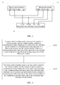
- FIG. 1 is a structural block diagram of the cordless digital telephone set.
- the cordless digital telephone set includes a base 1 and at least one cordless handset 2.
- the base 1 includes: a main control module 11, a subscriber line interface circuit module 12, and a Bluetooth module 13; in addition, the base 1 further includes a switch module 14.
- the switch module 14 When the switch module 14 receives a first control signal that is sent by the main control module 11, the switch module 14 connects a communication data output pin of the subscriber line interface circuit module 12 to a communication data input pin of the Bluetooth module 13; and connects a communication data input pin of the subscriber line interface circuit module 12 to a communication data output pin of the Bluetooth module 13.
- the switch module 14 when the switch module 14 receives a second control signal that is sent by the main control module 11, the switch module 14 connects a communication data output pin of the main control module 11 to the communication data input pin of the subscriber line interface circuit module 12; and connects a communication data input pin of the main control module 11 to the communication data output pin of the subscriber line interface circuit module 12.
- first control signal and the second control signal may be level signals, for example, the first control signal is a high level signal, and the second control signal is a low level signal, which is not specifically limited in this embodiment of the present invention.
- FIG. 1 shows multiple cordless handsets 2. According to different driving manners, two cases may occur for the multiple cordless handsets 2. First: one of the multiple cordless handsets 2 is a first cordless handset playing a leading role, and the other cordless handsets all complete voice data exchange work with the base by using the first cordless handset; second: the multiple cordless handsets 2 are equal, that is, any cordless handset can directly complete a process of voice data exchange with the base. It should be noted that this embodiment of the present invention focuses on introducing the base of the cordless digital telephone set. As for types of the handsets, no further limitations are set herein.
- the switch module includes a first single pole double throw switch and a second single pole double throw switch, and the first single pole double throw switch and the second single pole double throw switch both include a first end and a second end.
- the main control module 11 acquires voice data, and sends the voice data to the subscriber line interface circuit module 12, so that the interface line circuit module 12 completes a modulation process of converting the voice data from an analog signal to a digital signal.
- the first single pole double throw switch and the second single pole double throw switch receive a second control signal that is sent by the main control module.
- the first single pole double throw switch and the second single pole double throw switch are both thrown to the second end, so as to establish a communications channel between the subscriber line interface circuit module 12 and the main control module 11.
- a process of establishment of the communications channel between the subscriber line interface circuit module 12 and the main control module 11 may be described as follows: As shown in FIG. 2 , when the first single pole double throw switch is thrown to the second end, the communication data output pin (TX end) of the subscriber line interface circuit module 12 is connected to the communication data input pin (RX end) of the main control module 11 by using the second end of the first single pole double throw switch.
- the communication data input pin (RX end) of the subscriber line interface circuit module 12 is connected to the communication data output pin (TX end) of the main control module 11 by using that the second single pole double throw switch is thrown to the second end.
- the main control module 11 is connected to a CLK pin of the subscriber line interface circuit module 12 by using a CLK pin, and the main control module 11 is connected to a PSYN pin of the subscriber line interface circuit module 12 by using a PSYN pin. That is, the main control module 11 provides a clock signal and a frame synchronization signal to the subscriber line interface circuit module 12 (optionally, in this case, connections between the CLK pin and PSYN pin of the main control module 11 and corresponding pins of the Bluetooth module 13 may also be disconnected, so that the Bluetooth module 13 is in a non-working state).
- a bidirectional-communication voice data transmission channel between the main control module 11 and the subscriber line interface circuit module 12 has been established.
- the voice data can be transmitted from the main control module 11 to the subscriber line interface circuit module 12.
- the establishment of the communications channel is completed by two (or more) single pole double throw switches.
- a person skilled in the art may also use a single pole double throw switch group to complete the action of establishing the communications channel. Details are not described herein.
- the subscriber line interface circuit module 12 continues to send the voice data to the Bluetooth module 13, so that the Bluetooth module 13 further sends the voice data to a cordless handset.
- the first single pole double throw switch and the second single pole double throw switch receive a first control signal that is sent by the main control module.
- the first single pole double throw switch and the second single pole double throw switch are both thrown to the first end, so as to establish a communications channel between the subscriber line interface circuit module 12 and the Bluetooth module 13 that are under control of the main control module 11.
- a process of establishment of the communications channel between the subscriber line interface circuit module 12 and the Bluetooth module 13 that are under control of the main control module 11 may be described as follows: As shown in FIG.
- the communication data output pin (TX end) of the subscriber line interface circuit module 12 is connected to the communication data input pin (RX end) of the Bluetooth module 13 by using the first end of the first single pole double throw switch.
- the communication data input pin (RX end) of the subscriber line interface circuit module 12 is connected to the communication data output pin (TX end) of the Bluetooth module 13 by using the first end of the second single pole double throw switch.
- the main control module 11 is separately connected to CLK pins of the subscriber line interface circuit module 12 and the Bluetooth module 13 by using the CLK pin, and the main control module 11 is connected to PSYN pins of the subscriber line interface circuit module 12 and the Bluetooth module 13 by using the PSYN pin. That is, the main control module 11 simultaneously provides a same clock signal and frame synchronization signal to the subscriber line interface circuit module 12 and the Bluetooth module 13.
- the subscriber line interface circuit module 12 and the Bluetooth module 13 are both controlled by the same clock signal and frame synchronization signal (because the clock signal and the frame synchronization signal are both provided by the main control module 11). Therefore, the subscriber line interface circuit module 12 and the Bluetooth module 13 can communicate with each other according to the same signal and frame synchronization signal by using the established bidirectional-communication voice data transmission channel, and the voice data is further transmitted from the subscriber line interface circuit module 12 to the Bluetooth module 13.
- the Bluetooth module 13 sends the received voice data to a corresponding cordless handset.
- a transmission path of voice data in the base of a cordless digital telephone set provided in this embodiment of the present invention may be described as follows: the main control module 11-the subscriber line interface circuit module 12-the Bluetooth module 13. Therefore, the transmission path of the base of a cordless digital telephone set provided in this embodiment of the present invention is better than that of a base of a cordless digital telephone set in the prior art.
- the foregoing established voice data transmission channel can be used for bidirectional communication. Therefore, the voice data can also be transmitted along the following transmission path in the base of a cordless digital telephone set provided in this embodiment of the present invention: the Bluetooth module 13-the subscriber line interface circuit module 12-the main control module 11.
- This embodiment of the present invention provides a base of a cordless digital telephone set.
- a switch module when the switch module receives a high level control signal that is sent by a main control module, a subscriber line interface circuit module and a Bluetooth module establish a direct communication interconnection by using the switch module, so as to optimize a transmission path of voice data in the base of a cordless digital telephone set, thereby reducing load of the main control module.
- an embodiment of the present invention provides a cordless digital telephone set, as shown in FIG. 1 .
- the cordless digital telephone set includes the base 1 and the at least one cordless handset 2 that are mentioned in the foregoing embodiment.
- the base 1 completes exchange of voice data with the handset 2 by means of wireless communication.
- a frequency band for the wireless communication is any one or several of 2.4 GHZ, 1.8 GHZ, 5.8 GHZ, and 45 MHZ to 49 MHZ.
- an embodiment of the present invention further provides a voice data transmitting method.
- the voice data transmitting method is based on the base of a cordless digital telephone set mentioned in the foregoing embodiment.
- a structure of the base of a cordless digital telephone set is shown in FIG. 1 .
- the base 1 includes a main control module 11, a subscriber line interface circuit module 12, a Bluetooth module 13, and a switch module 14.
- the voice data transmitting method is shown in FIG. 4 , including:
- this embodiment of the present invention provides a voice data transmitting method, and the voice data transmitting method is based on the base of a cordless digital telephone set provided in the foregoing embodiment.
- the voice data transmitting method is based on the base of a cordless digital telephone set provided in the foregoing embodiment.
- For specific steps of the voice data transmitting method refer to a related description about the base of a cordless digital telephone set in the foregoing embodiment. Details are not described herein again.
- a structure of the cordless digital telephone set in this embodiment of the present invention also includes the base of a cordless digital telephone set in the foregoing embodiment, and is not described herein again.
- the embodiments of the present invention provide a cordless digital telephone set and a voice data transmitting method.
- a switch module when the switch module receives a first control signal that is sent by a main control module, a subscriber line interface circuit module and a Bluetooth module establish a direct communication interconnection by using the switch module, so as to optimize a transmission path of voice data in the base of a cordless digital telephone set, thereby reducing load of the main control module.
Landscapes
- Engineering & Computer Science (AREA)
- Computer Networks & Wireless Communication (AREA)
- Signal Processing (AREA)
- Human Computer Interaction (AREA)
- Mobile Radio Communication Systems (AREA)
- Telephone Function (AREA)
Abstract
Description
- The present invention relates to the field of digital communications, and in particular, to a base of a cordless digital telephone set, a cordless digital telephone set, and a voice data transmitting method.
- With development of communications technologies, interconnection between phones and people becomes closer. As a common phone type, a cordless digital telephone set uses a radio wave as a medium to implement "cordless" connection between a base and a handset, which overcomes constraint from a phone cord between a conventional telephone set and its handset, and brings great convenience and more flexible call experience for people.
- Using an existing cordless digital telephone set as an example, generally, the cordless digital telephone set includes a base and at least one cordless handset. Further, the base includes a main control module, a subscriber line interface circuit module, and a Bluetooth module. The subscriber line interface circuit (English: Subscriber line interface circuit, SLIC for short) module is configured to process analog voice data, and modulate the analog voice data into corresponding digital voice data by means of pulse code modulation. Based on characteristics of Bluetooth communication, such as a fast speed and good confidentiality, the Bluetooth module is configured to complete a process of voice data exchange between the base and the handset.
- However, according to a rule of classifying digital communications system working modes, it can be found that in the process of transferring the voice data by the main control module, the subscriber line interface circuit module, and the Bluetooth module, the main control module works as a primary device. The subscriber line interface circuit module and the Bluetooth module both work as secondary devices. Using a working process in which the base sends voice data to the handset as an example, a transmission path of the voice data may be described as follows: the main control module-the subscriber line interface circuit module-the main control module-the Bluetooth module-a module corresponding to the handset (details of specific processing of the voice data by the modules are omitted). Therefore, for the base of the existing cordless digital telephone set, the main control module needs to bear relatively heavy workload during normal work, and the transmission path of the voice data is inappropriate.
- Embodiments of the present invention provide a base of a cordless digital telephone set, a cordless digital telephone set, and a voice data transmitting method. In the base of a cordless digital telephone set, when receiving a high level control signal that is sent by a main control module, a switch module establishes a communications channel by using which a subscriber circuit module is directly interconnected to a Bluetooth module, thereby reducing workload of the main control module, and optimizing a transmission path of voice data.
- To resolve the foregoing technical problem, the following technical solutions are used in the embodiments of the present invention:
- According to one aspect, an embodiment of the present invention provides a base of a cordless digital telephone set, where the base includes: a main control module, a subscriber line interface circuit module, and a Bluetooth module, and the base further includes a switch module; and
when the switch module receives a first control signal that is sent by the main control module, the switch module connects a communication data output pin of the subscriber line interface circuit module to a communication data input pin of the Bluetooth module; and connects a communication data input pin of the subscriber line interface circuit module to a communication data output pin of the Bluetooth module. - In a first possible implementation manner, when the switch module receives a second control signal that is sent by the main control module, the switch module connects a communication data output pin of the main control module to the communication data input pin of the subscriber line interface circuit module; and connects a communication data input pin of the main control module to the communication data output pin of the subscriber line interface circuit module.
- In a second possible implementation manner, the switch module includes a first single pole double throw switch and a second single pole double throw switch;
when the first single pole double throw switch and the second single pole double throw switch receive the first control signal that is sent by the main control module, the first single pole double throw switch is thrown to a first end, so that the communication data output pin of the subscriber line interface circuit module is connected to the communication data input pin of the Bluetooth module by using the first end of the first single pole double throw switch; and the second single pole double throw switch is thrown to a first end, so that the communication data input pin of the subscriber line interface circuit module is connected to the communication data output pin of the Bluetooth module by using the first end of the second single pole double throw switch; and
when the first single pole double throw switch is thrown to the first end and the second single pole double throw switch is thrown to the first end, the main control module provides a clock signal and a frame synchronization signal to the subscriber line interface circuit module and the Bluetooth module. - With reference to the second possible implementation manner, in a third possible implementation manner, when the first single pole double throw switch and the second single pole double throw switch receive the second control signal that is sent by the main control module, the first single pole double throw switch is thrown to a second end, so that the communication data output pin of the subscriber line interface circuit module is connected to the communication data input pin of the main control module by using the second end of the first single pole double throw switch; and the second single pole double throw switch is thrown to a second end, so that the communication data input pin of the subscriber line interface circuit module is connected to the communication data output pin of the main control module by using the second end of the second single pole double throw switch; and
when the first single pole double throw switch is thrown to the second end and the second single pole double throw switch is thrown to the second end, the main control module provides a clock signal and a frame synchronization signal to the subscriber line interface circuit module. - According to another aspect, an embodiment of the present invention further provides a cordless digital telephone set, including the foregoing base and at least one cordless handset, where the base completes exchange of voice data with the cordless handset by means of wireless communication, and a frequency band for the wireless communication is any one or several of 2.4 GHZ, 1.8 GHZ, 5.8 GHZ, and 45 MHZ to 49 MHZ.
- According to still another aspect, an embodiment of the present invention further provides a voice data transmitting method, based on a base of a cordless digital telephone set of the foregoing structure, where the base of a cordless digital telephone set includes: a main control module, a subscriber line interface circuit module, a Bluetooth module, and a switch module; and the voice data transmitting method includes:
sending, by the main control module, a first control signal to the switch module; and according to the first control signal, connecting, by the switch module, a communication data output pin of the subscriber line interface circuit module to a communication data input pin of the Bluetooth module; and connecting, by the switch module, a communication data input pin of the subscriber line interface circuit module to a communication data output pin of the Bluetooth module. - In a first possible implementation manner, the voice data transmitting method further includes: sending, by the main control module, a second control signal to the switch module; and according to the second control signal, connecting, by the switch module, a communication data output pin of the main control module to the communication data input pin of the subscriber line interface circuit module; and connecting, by the switch module, a communication data input pin of the main control module to the communication data output pin of the subscriber line interface circuit module.
- The embodiments of the present invention provide a base of a cordless digital telephone set, a cordless digital telephone set, and a voice data transmitting method. With a disposed switch module, when the switch module receives a first control signal that is sent by a main control module, a subscriber line interface circuit module and a Bluetooth module establish a direct communication interconnection by using the switch module, so as to optimize a transmission path of voice data in the base of a cordless digital telephone set, thereby reducing load of the main control module.
-
-
FIG. 1 is a structural block diagram of a cordless digital telephone set according to an embodiment of the present invention; -
FIG. 2 is schematic diagram of circuit connection of a base of a cordless digital telephone set according to an embodiment of the present invention when a first single pole double throw switch and a second single pole double throw switch are both thrown to a second end; -
FIG. 3 is schematic diagram of circuit connection of a base of a cordless digital telephone set according to an embodiment of the present invention when a first single pole double throw switch and a second single pole double throw switch are both thrown to a first end; and -
FIG. 4 is a schematic flowchart of a voice data transmitting method according to an embodiment of the present invention. - Embodiments of the present invention provide a base of a cordless digital telephone set, a cordless digital telephone set, and a voice data transmitting method. In the base of a cordless digital telephone set, when receiving a first control signal that is sent by a main control module, a switch module establishes a communications channel by using which a subscriber circuit module is directly interconnected to a Bluetooth module, thereby reducing workload of the main control module, and optimizing a transmission path of voice data.
- The following clearly and completely describes the technical solutions in the embodiments of the present invention with reference to the accompanying drawings in the embodiments of the present invention. Apparently, the described embodiments are some but not all of the embodiments of the present invention. All other embodiments obtained by a person of ordinary skill in the art based on the embodiments of the present invention without creative efforts shall fall within the protection scope of the present invention.
- The embodiments of the present invention are described below in detail with reference to the following accompanying drawings.
- An embodiment of the present invention provides a base of a cordless digital telephone set, as shown in
FIG. 1 . It should be noted thatFIG. 1 is a structural block diagram of the cordless digital telephone set. The cordless digital telephone set includes abase 1 and at least onecordless handset 2. Further, thebase 1 includes: amain control module 11, a subscriber lineinterface circuit module 12, and a Bluetoothmodule 13; in addition, thebase 1 further includes aswitch module 14. When theswitch module 14 receives a first control signal that is sent by themain control module 11, theswitch module 14 connects a communication data output pin of the subscriber lineinterface circuit module 12 to a communication data input pin of the Bluetoothmodule 13; and connects a communication data input pin of the subscriber lineinterface circuit module 12 to a communication data output pin of the Bluetoothmodule 13. - Further, when the
switch module 14 receives a second control signal that is sent by themain control module 11, theswitch module 14 connects a communication data output pin of themain control module 11 to the communication data input pin of the subscriber lineinterface circuit module 12; and connects a communication data input pin of themain control module 11 to the communication data output pin of the subscriber lineinterface circuit module 12. - It should be noted that the first control signal and the second control signal may be level signals, for example, the first control signal is a high level signal, and the second control signal is a low level signal, which is not specifically limited in this embodiment of the present invention.
- As shown in
FIG. 1, FIG. 1 shows multiplecordless handsets 2. According to different driving manners, two cases may occur for the multiplecordless handsets 2. First: one of the multiplecordless handsets 2 is a first cordless handset playing a leading role, and the other cordless handsets all complete voice data exchange work with the base by using the first cordless handset; second: the multiplecordless handsets 2 are equal, that is, any cordless handset can directly complete a process of voice data exchange with the base. It should be noted that this embodiment of the present invention focuses on introducing the base of the cordless digital telephone set. As for types of the handsets, no further limitations are set herein. - Specifically, a situation of transmission of voice data in the base of a cordless digital telephone set provided in this embodiment of the present invention is introduced in detail by using a specific implementation manner as an example.
- It is assumed that the switch module includes a first single pole double throw switch and a second single pole double throw switch, and the first single pole double throw switch and the second single pole double throw switch both include a first end and a second end. First, as shown in
FIG. 2 , themain control module 11 acquires voice data, and sends the voice data to the subscriber lineinterface circuit module 12, so that the interfaceline circuit module 12 completes a modulation process of converting the voice data from an analog signal to a digital signal. - The first single pole double throw switch and the second single pole double throw switch receive a second control signal that is sent by the main control module. In this case, the first single pole double throw switch and the second single pole double throw switch are both thrown to the second end, so as to establish a communications channel between the subscriber line
interface circuit module 12 and themain control module 11. A process of establishment of the communications channel between the subscriber lineinterface circuit module 12 and themain control module 11 may be described as follows: As shown inFIG. 2 , when the first single pole double throw switch is thrown to the second end, the communication data output pin (TX end) of the subscriber lineinterface circuit module 12 is connected to the communication data input pin (RX end) of themain control module 11 by using the second end of the first single pole double throw switch. When the second single pole double throw switch is thrown to the second end, the communication data input pin (RX end) of the subscriber lineinterface circuit module 12 is connected to the communication data output pin (TX end) of themain control module 11 by using that the second single pole double throw switch is thrown to the second end. - In addition, the
main control module 11 is connected to a CLK pin of the subscriber lineinterface circuit module 12 by using a CLK pin, and themain control module 11 is connected to a PSYN pin of the subscriber lineinterface circuit module 12 by using a PSYN pin. That is, themain control module 11 provides a clock signal and a frame synchronization signal to the subscriber line interface circuit module 12 (optionally, in this case, connections between the CLK pin and PSYN pin of themain control module 11 and corresponding pins of the Bluetoothmodule 13 may also be disconnected, so that the Bluetoothmodule 13 is in a non-working state). - So far, a bidirectional-communication voice data transmission channel between the
main control module 11 and the subscriber lineinterface circuit module 12 has been established. The voice data can be transmitted from themain control module 11 to the subscriber lineinterface circuit module 12. - It should be noted that, as shown in
FIG. 2 , the establishment of the communications channel is completed by two (or more) single pole double throw switches. Certainly, a person skilled in the art may also use a single pole double throw switch group to complete the action of establishing the communications channel. Details are not described herein. - Then, as shown in
FIG. 3 , after completing modulation of converting the voice data from an analog signal to a digital signal, the subscriber lineinterface circuit module 12 continues to send the voice data to theBluetooth module 13, so that theBluetooth module 13 further sends the voice data to a cordless handset. - The first single pole double throw switch and the second single pole double throw switch receive a first control signal that is sent by the main control module. In this case, the first single pole double throw switch and the second single pole double throw switch are both thrown to the first end, so as to establish a communications channel between the subscriber line
interface circuit module 12 and theBluetooth module 13 that are under control of themain control module 11. A process of establishment of the communications channel between the subscriber lineinterface circuit module 12 and theBluetooth module 13 that are under control of themain control module 11 may be described as follows: As shown inFIG. 3 , when the first single pole double throw switch is thrown to the first end, the communication data output pin (TX end) of the subscriber lineinterface circuit module 12 is connected to the communication data input pin (RX end) of theBluetooth module 13 by using the first end of the first single pole double throw switch. When the second single pole double throw switch is thrown to the first end, the communication data input pin (RX end) of the subscriber lineinterface circuit module 12 is connected to the communication data output pin (TX end) of theBluetooth module 13 by using the first end of the second single pole double throw switch. - In addition, the
main control module 11 is separately connected to CLK pins of the subscriber lineinterface circuit module 12 and theBluetooth module 13 by using the CLK pin, and themain control module 11 is connected to PSYN pins of the subscriber lineinterface circuit module 12 and theBluetooth module 13 by using the PSYN pin. That is, themain control module 11 simultaneously provides a same clock signal and frame synchronization signal to the subscriber lineinterface circuit module 12 and theBluetooth module 13. - So far, the subscriber line
interface circuit module 12 and theBluetooth module 13 are both controlled by the same clock signal and frame synchronization signal (because the clock signal and the frame synchronization signal are both provided by the main control module 11). Therefore, the subscriber lineinterface circuit module 12 and theBluetooth module 13 can communicate with each other according to the same signal and frame synchronization signal by using the established bidirectional-communication voice data transmission channel, and the voice data is further transmitted from the subscriber lineinterface circuit module 12 to theBluetooth module 13. - Then, the
Bluetooth module 13 sends the received voice data to a corresponding cordless handset. - It should be noted that it can be clearly determined according to the foregoing description that a transmission path of voice data in the base of a cordless digital telephone set provided in this embodiment of the present invention may be described as follows: the main control module 11-the subscriber line interface circuit module 12-the
Bluetooth module 13. Therefore, the transmission path of the base of a cordless digital telephone set provided in this embodiment of the present invention is better than that of a base of a cordless digital telephone set in the prior art. - In addition, the foregoing established voice data transmission channel can be used for bidirectional communication. Therefore, the voice data can also be transmitted along the following transmission path in the base of a cordless digital telephone set provided in this embodiment of the present invention: the Bluetooth module 13-the subscriber line interface circuit module 12-the
main control module 11. - This embodiment of the present invention provides a base of a cordless digital telephone set. With a disposed switch module, when the switch module receives a high level control signal that is sent by a main control module, a subscriber line interface circuit module and a Bluetooth module establish a direct communication interconnection by using the switch module, so as to optimize a transmission path of voice data in the base of a cordless digital telephone set, thereby reducing load of the main control module.
- In another aspect, an embodiment of the present invention provides a cordless digital telephone set, as shown in
FIG. 1 . The cordless digital telephone set includes thebase 1 and the at least onecordless handset 2 that are mentioned in the foregoing embodiment. Thebase 1 completes exchange of voice data with thehandset 2 by means of wireless communication. Further, a frequency band for the wireless communication is any one or several of 2.4 GHZ, 1.8 GHZ, 5.8 GHZ, and 45 MHZ to 49 MHZ. - In still another aspect, an embodiment of the present invention further provides a voice data transmitting method. The voice data transmitting method is based on the base of a cordless digital telephone set mentioned in the foregoing embodiment. A structure of the base of a cordless digital telephone set is shown in
FIG. 1 . Thebase 1 includes amain control module 11, a subscriber lineinterface circuit module 12, aBluetooth module 13, and aswitch module 14. - The voice data transmitting method is shown in
FIG. 4 , including: - Step S101: The main control module sends a first control signal to the switch module, and the switch module connects a communication data output pin of the subscriber line interface circuit module to a communication data input pin of the Bluetooth module; and the switch module connects a communication data input pin of the subscriber line interface circuit module to a communication data output pin of the Bluetooth module.
- Step S102: The main control module sends a second control signal to the switch module, and the switch module connects a communication data output pin of the main control module to the communication data input pin of the subscriber line interface circuit module; and the switch module connects a communication data input pin of the main control module to the communication data output pin of the subscriber line interface circuit module.
- It should be noted that this embodiment of the present invention provides a voice data transmitting method, and the voice data transmitting method is based on the base of a cordless digital telephone set provided in the foregoing embodiment. For specific steps of the voice data transmitting method, refer to a related description about the base of a cordless digital telephone set in the foregoing embodiment. Details are not described herein again. A structure of the cordless digital telephone set in this embodiment of the present invention also includes the base of a cordless digital telephone set in the foregoing embodiment, and is not described herein again.
- The embodiments of the present invention provide a cordless digital telephone set and a voice data transmitting method. In a base of a cordless digital telephone set, with a disposed switch module, when the switch module receives a first control signal that is sent by a main control module, a subscriber line interface circuit module and a Bluetooth module establish a direct communication interconnection by using the switch module, so as to optimize a transmission path of voice data in the base of a cordless digital telephone set, thereby reducing load of the main control module.
- The foregoing descriptions are merely specific implementation manners of the present invention, but are not intended to limit the protection scope of the present invention. Any variation or replacement readily figured out by a person skilled in the art within the technical scope disclosed in the present invention shall fall within the protection scope of the present invention. Therefore, the protection scope of the present invention shall be subject to the protection scope of the claims.
Claims (7)
- A base of a cordless digital telephone set, wherein the base comprises: a main control module, a subscriber line interface circuit module, and a Bluetooth module, and the base further comprises a switch module; and
when the switch module receives a first control signal that is sent by the main control module, the switch module connects a communication data output pin of the subscriber line interface circuit module to a communication data input pin of the Bluetooth module; and connects a communication data input pin of the subscriber line interface circuit module to a communication data output pin of the Bluetooth module. - The base of a cordless digital telephone set according to claim 1, wherein when the switch module receives a second control signal that is sent by the main control module, the switch module connects a communication data output pin of the main control module to the communication data input pin of the subscriber line interface circuit module; and connects a communication data input pin of the main control module to the communication data output pin of the subscriber line interface circuit module.
- The base of a cordless digital telephone set according to claim 1 or 2, wherein the switch module comprises a first single pole double throw switch and a second single pole double throw switch;
when the first single pole double throw switch and the second single pole double throw switch receive the first control signal that is sent by the main control module, the first single pole double throw switch is thrown to a first end, so that the communication data output pin of the subscriber line interface circuit module is connected to the communication data input pin of the Bluetooth module by using the first end of the first single pole double throw switch; and the second single pole double throw switch is thrown to a first end, so that the communication data input pin of the subscriber line interface circuit module is connected to the communication data output pin of the Bluetooth module by using the first end of the second single pole double throw switch; and
when the first single pole double throw switch is thrown to the first end and the second single pole double throw switch is thrown to the first end, the main control module provides a clock signal and a frame synchronization signal to the subscriber line interface circuit module and the Bluetooth module. - The base of a cordless digital telephone set according to claim 3, wherein when the first single pole double throw switch and the second single pole double throw switch receive the second control signal that is sent by the main control module, the first single pole double throw switch is thrown to a second end, so that the communication data output pin of the subscriber line interface circuit module is connected to the communication data input pin of the main control module by using the second end of the first single pole double throw switch; and the second single pole double throw switch is thrown to a second end, so that the communication data input pin of the subscriber line interface circuit module is connected to the communication data output pin of the main control module by using the second end of the second single pole double throw switch; and
when the first single pole double throw switch is thrown to the second end and the second single pole double throw switch is thrown to the second end, the main control module provides a clock signal and a frame synchronization signal to the subscriber line interface circuit module. - A cordless digital telephone set, comprising the base according to any one of claims 1 to 4 and at least one cordless handset, wherein the base completes exchange of voice data with the cordless handset by means of wireless communication, and a frequency band for the wireless communication is any one or several of 2.4 GHZ, 1.8 GHZ, 5.8 GHZ, and 45 MHZ to 49 MHZ.
- A voice data transmitting method, based on the base of a cordless digital telephone set according to any one of claims 1 to 4, wherein the base of a cordless digital telephone set comprises:a main control module, a subscriber line interface circuit module, a Bluetooth module, and a switch module; and the voice data transmitting method comprises:sending, by the main control module, a first control signal to the switch module; andaccording to the first control signal, connecting, by the switch module, a communication data output pin of the subscriber line interface circuit module to a communication data input pin of the Bluetooth module; and connecting a communication data input pin of the subscriber line interface circuit module to a communication data output pin of the Bluetooth module.
- The voice data transmitting method according to claim 6, further comprising:sending, by the main control module, a second control signal to the switch module; andaccording to the second control signal, connecting, by the switch module, a communication data output pin of the main control module to the communication data input pin of the subscriber line interface circuit module; and connecting a communication data input pin of the main control module to the communication data output pin of the subscriber line interface circuit module.
Applications Claiming Priority (1)
| Application Number | Priority Date | Filing Date | Title |
|---|---|---|---|
| PCT/CN2014/070412 WO2015103761A1 (en) | 2014-01-09 | 2014-01-09 | Cordless digital telephone main machine, cordless digital telephone and voice data transmission method |
Publications (3)
| Publication Number | Publication Date |
|---|---|
| EP3076644A1 true EP3076644A1 (en) | 2016-10-05 |
| EP3076644A4 EP3076644A4 (en) | 2016-12-28 |
| EP3076644B1 EP3076644B1 (en) | 2019-03-06 |
Family
ID=53523456
Family Applications (1)
| Application Number | Title | Priority Date | Filing Date |
|---|---|---|---|
| EP14877589.3A Active EP3076644B1 (en) | 2014-01-09 | 2014-01-09 | Base for cordless digital telephone set and corresponding voice data transmission method |
Country Status (4)
| Country | Link |
|---|---|
| US (1) | US9699293B2 (en) |
| EP (1) | EP3076644B1 (en) |
| CN (1) | CN105684402B (en) |
| WO (1) | WO2015103761A1 (en) |
Family Cites Families (16)
| Publication number | Priority date | Publication date | Assignee | Title |
|---|---|---|---|---|
| US6219417B1 (en) * | 1997-06-06 | 2001-04-17 | Advanced Micro Devices, Inc. | Ring trip detection in a communication system |
| US6608889B2 (en) * | 2001-01-25 | 2003-08-19 | Agere Systems Inc. | Telephone having convenience feature data transfer capability |
| US6778824B2 (en) * | 2002-06-19 | 2004-08-17 | Telular Corp. | Apparatus for wirelessly-coupling a bluetooth-wireless cellular mobile handset to a docking station for connecting a standard telephone set to the cellular network |
| GB0317130D0 (en) * | 2003-07-22 | 2003-08-27 | Mansella Ltd | Bluetooth communication |
| JP5042629B2 (en) * | 2003-11-13 | 2012-10-03 | トムソン ライセンシング | Integrated cellular / PCS-POTS communication system |
| CN100466535C (en) * | 2004-12-23 | 2009-03-04 | 华为技术有限公司 | Device and method for implementing switch between IP network and PSTN for users |
| TW200737910A (en) * | 2006-03-27 | 2007-10-01 | F3 Inc | Switching method between VoIP phone and traditional phone |
| TW200812350A (en) * | 2006-08-25 | 2008-03-01 | F3 Inc | Three-in-one automatic adapting-system |
| CN101193373A (en) * | 2006-11-27 | 2008-06-04 | 中兴通讯股份有限公司 | Audio control circuit for TD-SCDMA/GSM dual-mode mobile phone |
| US7925296B2 (en) | 2007-05-07 | 2011-04-12 | Sure Best Limited | Intergrated communication apparatus |
| CN101442837A (en) * | 2007-11-21 | 2009-05-27 | 宁波萨基姆波导研发有限公司 | Double-card double-standby mobile phone with Bluetooth function and implementing method thereof |
| CN101232686B (en) | 2008-02-27 | 2011-01-19 | 中兴通讯股份有限公司 | Method for implementing multimodule mobile phone blue tooth hands-free voice switch |
| CN101287237A (en) | 2008-05-28 | 2008-10-15 | 德信无线通讯科技(北京)有限公司 | Double-mode double-standby mobile phone and voice signal transmitting method for the same |
| CN101577986B (en) * | 2009-06-02 | 2011-05-25 | 中兴通讯股份有限公司 | Mobile communication terminal |
| US9025583B2 (en) * | 2009-07-09 | 2015-05-05 | Mediatek Inc. | System for the coexistence between a plurality of wireless communication module sharing single antenna |
| CN102468874A (en) | 2010-11-18 | 2012-05-23 | 西安龙飞软件有限公司 | Bluetooth realization mode for dual-mode phone |
-
2014
- 2014-01-09 US US15/110,657 patent/US9699293B2/en active Active
- 2014-01-09 WO PCT/CN2014/070412 patent/WO2015103761A1/en active Application Filing
- 2014-01-09 EP EP14877589.3A patent/EP3076644B1/en active Active
- 2014-01-09 CN CN201480060084.6A patent/CN105684402B/en not_active Expired - Fee Related
Also Published As
| Publication number | Publication date |
|---|---|
| EP3076644A4 (en) | 2016-12-28 |
| US20160344857A1 (en) | 2016-11-24 |
| CN105684402A (en) | 2016-06-15 |
| EP3076644B1 (en) | 2019-03-06 |
| CN105684402B (en) | 2019-01-11 |
| US9699293B2 (en) | 2017-07-04 |
| WO2015103761A1 (en) | 2015-07-16 |
Similar Documents
| Publication | Publication Date | Title |
|---|---|---|
| JPH04342346A (en) | System for speaking between slave sets for cordless telephone | |
| EP2838313B1 (en) | Portable terminal auxiliary device having satellite communication function | |
| JP2017512423A (en) | Multi-mode wireless terminal | |
| CN112219423B (en) | Transmission path switching method and device | |
| CN102857609B (en) | Radio signal is transmitted between earphone and base station | |
| CN104618571A (en) | Method for implementing call audio switching based on Bluetooth protocol and mobile terminal | |
| CN105430541A (en) | Wireless microphone automatic frequency matching method and device | |
| CN104243684A (en) | Method and electronic device for wireless communication | |
| CN201657087U (en) | Mobile phone controlling frequency-modulation radio via earphone | |
| CN102387258A (en) | Double-mode and dual-standby mobile terminal comprising LTE (Long Term Evolution) network mode | |
| US9699293B2 (en) | Base of cordless digital telephone set, cordless digital telephone set, and voice data transmitting method | |
| CN102624963A (en) | Mobile phone with full duplex wireless intercom function, and implementation method thereof | |
| CN201345679Y (en) | Double-module wireless terminal | |
| CN205142536U (en) | Wireless access apparatus | |
| KR100606717B1 (en) | A Dual UART circuit for a mobile telecommunication device | |
| CN111132293B (en) | Information transmission method, equipment and system | |
| CN101360292A (en) | Method and system implementing dual SIM card interchanging supported by single Bluetooth in mobile phone | |
| CN201869269U (en) | High-level multimode wireless system terminal | |
| CN104272602B (en) | Method and communication equipment for mobile radio | |
| CN219644064U (en) | Wireless microphone system supporting dual modes of receiving and transmitting | |
| WO2022022737A1 (en) | Method for configuring information transmission mode, and terminal and network-side device | |
| CN101420779B (en) | Double-mode double-standby mobile communication equipment and method for sensing call reception | |
| US20140120897A1 (en) | Communication integration system and method thereof | |
| JP3853569B2 (en) | Wireless communication device | |
| CN203788278U (en) | Wireless communication machine and wireless communication equipment |
Legal Events
| Date | Code | Title | Description |
|---|---|---|---|
| PUAI | Public reference made under article 153(3) epc to a published international application that has entered the european phase |
Free format text: ORIGINAL CODE: 0009012 |
|
| 17P | Request for examination filed |
Effective date: 20160630 |
|
| AK | Designated contracting states |
Kind code of ref document: A1 Designated state(s): AL AT BE BG CH CY CZ DE DK EE ES FI FR GB GR HR HU IE IS IT LI LT LU LV MC MK MT NL NO PL PT RO RS SE SI SK SM TR |
|
| AX | Request for extension of the european patent |
Extension state: BA ME |
|
| A4 | Supplementary search report drawn up and despatched |
Effective date: 20161124 |
|
| RIC1 | Information provided on ipc code assigned before grant |
Ipc: H04W 88/02 20090101ALI20161118BHEP Ipc: H04M 1/725 20060101AFI20161118BHEP |
|
| DAX | Request for extension of the european patent (deleted) | ||
| GRAP | Despatch of communication of intention to grant a patent |
Free format text: ORIGINAL CODE: EPIDOSNIGR1 |
|
| STAA | Information on the status of an ep patent application or granted ep patent |
Free format text: STATUS: GRANT OF PATENT IS INTENDED |
|
| RIC1 | Information provided on ipc code assigned before grant |
Ipc: H04W 88/02 20090101ALI20180629BHEP Ipc: H04M 1/725 20060101AFI20180629BHEP Ipc: H04M 3/00 20060101ALI20180629BHEP |
|
| INTG | Intention to grant announced |
Effective date: 20180802 |
|
| GRAS | Grant fee paid |
Free format text: ORIGINAL CODE: EPIDOSNIGR3 |
|
| RAP1 | Party data changed (applicant data changed or rights of an application transferred) |
Owner name: HUAWEI DEVICE (SHENZHEN) CO., LTD. |
|
| RAP1 | Party data changed (applicant data changed or rights of an application transferred) |
Owner name: HUAWEI DEVICE CO., LTD. |
|
| GRAA | (expected) grant |
Free format text: ORIGINAL CODE: 0009210 |
|
| STAA | Information on the status of an ep patent application or granted ep patent |
Free format text: STATUS: THE PATENT HAS BEEN GRANTED |
|
| AK | Designated contracting states |
Kind code of ref document: B1 Designated state(s): AL AT BE BG CH CY CZ DE DK EE ES FI FR GB GR HR HU IE IS IT LI LT LU LV MC MK MT NL NO PL PT RO RS SE SI SK SM TR |
|
| REG | Reference to a national code |
Ref country code: GB Ref legal event code: FG4D |
|
| REG | Reference to a national code |
Ref country code: CH Ref legal event code: EP Ref country code: AT Ref legal event code: REF Ref document number: 1106137 Country of ref document: AT Kind code of ref document: T Effective date: 20190315 |
|
| REG | Reference to a national code |
Ref country code: DE Ref legal event code: R096 Ref document number: 602014042592 Country of ref document: DE |
|
| REG | Reference to a national code |
Ref country code: IE Ref legal event code: FG4D |
|
| REG | Reference to a national code |
Ref country code: NL Ref legal event code: FP |
|
| REG | Reference to a national code |
Ref country code: LT Ref legal event code: MG4D |
|
| PG25 | Lapsed in a contracting state [announced via postgrant information from national office to epo] |
Ref country code: SE Free format text: LAPSE BECAUSE OF FAILURE TO SUBMIT A TRANSLATION OF THE DESCRIPTION OR TO PAY THE FEE WITHIN THE PRESCRIBED TIME-LIMIT Effective date: 20190306 Ref country code: FI Free format text: LAPSE BECAUSE OF FAILURE TO SUBMIT A TRANSLATION OF THE DESCRIPTION OR TO PAY THE FEE WITHIN THE PRESCRIBED TIME-LIMIT Effective date: 20190306 Ref country code: NO Free format text: LAPSE BECAUSE OF FAILURE TO SUBMIT A TRANSLATION OF THE DESCRIPTION OR TO PAY THE FEE WITHIN THE PRESCRIBED TIME-LIMIT Effective date: 20190606 Ref country code: LT Free format text: LAPSE BECAUSE OF FAILURE TO SUBMIT A TRANSLATION OF THE DESCRIPTION OR TO PAY THE FEE WITHIN THE PRESCRIBED TIME-LIMIT Effective date: 20190306 |
|
| PG25 | Lapsed in a contracting state [announced via postgrant information from national office to epo] |
Ref country code: BG Free format text: LAPSE BECAUSE OF FAILURE TO SUBMIT A TRANSLATION OF THE DESCRIPTION OR TO PAY THE FEE WITHIN THE PRESCRIBED TIME-LIMIT Effective date: 20190606 Ref country code: GR Free format text: LAPSE BECAUSE OF FAILURE TO SUBMIT A TRANSLATION OF THE DESCRIPTION OR TO PAY THE FEE WITHIN THE PRESCRIBED TIME-LIMIT Effective date: 20190607 Ref country code: HR Free format text: LAPSE BECAUSE OF FAILURE TO SUBMIT A TRANSLATION OF THE DESCRIPTION OR TO PAY THE FEE WITHIN THE PRESCRIBED TIME-LIMIT Effective date: 20190306 Ref country code: LV Free format text: LAPSE BECAUSE OF FAILURE TO SUBMIT A TRANSLATION OF THE DESCRIPTION OR TO PAY THE FEE WITHIN THE PRESCRIBED TIME-LIMIT Effective date: 20190306 Ref country code: RS Free format text: LAPSE BECAUSE OF FAILURE TO SUBMIT A TRANSLATION OF THE DESCRIPTION OR TO PAY THE FEE WITHIN THE PRESCRIBED TIME-LIMIT Effective date: 20190306 |
|
| REG | Reference to a national code |
Ref country code: AT Ref legal event code: MK05 Ref document number: 1106137 Country of ref document: AT Kind code of ref document: T Effective date: 20190306 |
|
| PG25 | Lapsed in a contracting state [announced via postgrant information from national office to epo] |
Ref country code: RO Free format text: LAPSE BECAUSE OF FAILURE TO SUBMIT A TRANSLATION OF THE DESCRIPTION OR TO PAY THE FEE WITHIN THE PRESCRIBED TIME-LIMIT Effective date: 20190306 Ref country code: IT Free format text: LAPSE BECAUSE OF FAILURE TO SUBMIT A TRANSLATION OF THE DESCRIPTION OR TO PAY THE FEE WITHIN THE PRESCRIBED TIME-LIMIT Effective date: 20190306 Ref country code: EE Free format text: LAPSE BECAUSE OF FAILURE TO SUBMIT A TRANSLATION OF THE DESCRIPTION OR TO PAY THE FEE WITHIN THE PRESCRIBED TIME-LIMIT Effective date: 20190306 Ref country code: CZ Free format text: LAPSE BECAUSE OF FAILURE TO SUBMIT A TRANSLATION OF THE DESCRIPTION OR TO PAY THE FEE WITHIN THE PRESCRIBED TIME-LIMIT Effective date: 20190306 Ref country code: ES Free format text: LAPSE BECAUSE OF FAILURE TO SUBMIT A TRANSLATION OF THE DESCRIPTION OR TO PAY THE FEE WITHIN THE PRESCRIBED TIME-LIMIT Effective date: 20190306 Ref country code: PT Free format text: LAPSE BECAUSE OF FAILURE TO SUBMIT A TRANSLATION OF THE DESCRIPTION OR TO PAY THE FEE WITHIN THE PRESCRIBED TIME-LIMIT Effective date: 20190706 Ref country code: AL Free format text: LAPSE BECAUSE OF FAILURE TO SUBMIT A TRANSLATION OF THE DESCRIPTION OR TO PAY THE FEE WITHIN THE PRESCRIBED TIME-LIMIT Effective date: 20190306 Ref country code: SK Free format text: LAPSE BECAUSE OF FAILURE TO SUBMIT A TRANSLATION OF THE DESCRIPTION OR TO PAY THE FEE WITHIN THE PRESCRIBED TIME-LIMIT Effective date: 20190306 |
|
| PG25 | Lapsed in a contracting state [announced via postgrant information from national office to epo] |
Ref country code: PL Free format text: LAPSE BECAUSE OF FAILURE TO SUBMIT A TRANSLATION OF THE DESCRIPTION OR TO PAY THE FEE WITHIN THE PRESCRIBED TIME-LIMIT Effective date: 20190306 Ref country code: SM Free format text: LAPSE BECAUSE OF FAILURE TO SUBMIT A TRANSLATION OF THE DESCRIPTION OR TO PAY THE FEE WITHIN THE PRESCRIBED TIME-LIMIT Effective date: 20190306 |
|
| REG | Reference to a national code |
Ref country code: DE Ref legal event code: R097 Ref document number: 602014042592 Country of ref document: DE |
|
| PG25 | Lapsed in a contracting state [announced via postgrant information from national office to epo] |
Ref country code: AT Free format text: LAPSE BECAUSE OF FAILURE TO SUBMIT A TRANSLATION OF THE DESCRIPTION OR TO PAY THE FEE WITHIN THE PRESCRIBED TIME-LIMIT Effective date: 20190306 Ref country code: IS Free format text: LAPSE BECAUSE OF FAILURE TO SUBMIT A TRANSLATION OF THE DESCRIPTION OR TO PAY THE FEE WITHIN THE PRESCRIBED TIME-LIMIT Effective date: 20190706 |
|
| PLBE | No opposition filed within time limit |
Free format text: ORIGINAL CODE: 0009261 |
|
| STAA | Information on the status of an ep patent application or granted ep patent |
Free format text: STATUS: NO OPPOSITION FILED WITHIN TIME LIMIT |
|
| PG25 | Lapsed in a contracting state [announced via postgrant information from national office to epo] |
Ref country code: DK Free format text: LAPSE BECAUSE OF FAILURE TO SUBMIT A TRANSLATION OF THE DESCRIPTION OR TO PAY THE FEE WITHIN THE PRESCRIBED TIME-LIMIT Effective date: 20190306 |
|
| 26N | No opposition filed |
Effective date: 20191209 |
|
| PG25 | Lapsed in a contracting state [announced via postgrant information from national office to epo] |
Ref country code: SI Free format text: LAPSE BECAUSE OF FAILURE TO SUBMIT A TRANSLATION OF THE DESCRIPTION OR TO PAY THE FEE WITHIN THE PRESCRIBED TIME-LIMIT Effective date: 20190306 |
|
| PG25 | Lapsed in a contracting state [announced via postgrant information from national office to epo] |
Ref country code: TR Free format text: LAPSE BECAUSE OF FAILURE TO SUBMIT A TRANSLATION OF THE DESCRIPTION OR TO PAY THE FEE WITHIN THE PRESCRIBED TIME-LIMIT Effective date: 20190306 |
|
| PG25 | Lapsed in a contracting state [announced via postgrant information from national office to epo] |
Ref country code: MC Free format text: LAPSE BECAUSE OF FAILURE TO SUBMIT A TRANSLATION OF THE DESCRIPTION OR TO PAY THE FEE WITHIN THE PRESCRIBED TIME-LIMIT Effective date: 20190306 |
|
| REG | Reference to a national code |
Ref country code: CH Ref legal event code: PL |
|
| REG | Reference to a national code |
Ref country code: BE Ref legal event code: MM Effective date: 20200131 |
|
| PG25 | Lapsed in a contracting state [announced via postgrant information from national office to epo] |
Ref country code: LU Free format text: LAPSE BECAUSE OF NON-PAYMENT OF DUE FEES Effective date: 20200109 |
|
| PG25 | Lapsed in a contracting state [announced via postgrant information from national office to epo] |
Ref country code: CH Free format text: LAPSE BECAUSE OF NON-PAYMENT OF DUE FEES Effective date: 20200131 Ref country code: LI Free format text: LAPSE BECAUSE OF NON-PAYMENT OF DUE FEES Effective date: 20200131 Ref country code: BE Free format text: LAPSE BECAUSE OF NON-PAYMENT OF DUE FEES Effective date: 20200131 |
|
| REG | Reference to a national code |
Ref country code: DE Ref legal event code: R081 Ref document number: 602014042592 Country of ref document: DE Owner name: SHARP KABUSHIKI KAISHA, SAKAI-CITY, JP Free format text: FORMER OWNER: HUAWEI DEVICE CO., LTD., DONGGUAN, GUANGDONG, CN |
|
| PG25 | Lapsed in a contracting state [announced via postgrant information from national office to epo] |
Ref country code: IE Free format text: LAPSE BECAUSE OF NON-PAYMENT OF DUE FEES Effective date: 20200109 |
|
| PGFP | Annual fee paid to national office [announced via postgrant information from national office to epo] |
Ref country code: FR Payment date: 20201210 Year of fee payment: 8 Ref country code: GB Payment date: 20201230 Year of fee payment: 8 |
|
| REG | Reference to a national code |
Ref country code: NL Ref legal event code: PD Owner name: SHARP KABUSHIKI KAISHA; JP Free format text: DETAILS ASSIGNMENT: CHANGE OF OWNER(S), ASSIGNMENT; FORMER OWNER NAME: HUAWEI DEVICE CO., LTD. Effective date: 20210129 |
|
| REG | Reference to a national code |
Ref country code: GB Ref legal event code: 732E Free format text: REGISTERED BETWEEN 20210318 AND 20210324 |
|
| PGFP | Annual fee paid to national office [announced via postgrant information from national office to epo] |
Ref country code: NL Payment date: 20210113 Year of fee payment: 8 |
|
| PGFP | Annual fee paid to national office [announced via postgrant information from national office to epo] |
Ref country code: DE Payment date: 20201229 Year of fee payment: 8 |
|
| PG25 | Lapsed in a contracting state [announced via postgrant information from national office to epo] |
Ref country code: MT Free format text: LAPSE BECAUSE OF FAILURE TO SUBMIT A TRANSLATION OF THE DESCRIPTION OR TO PAY THE FEE WITHIN THE PRESCRIBED TIME-LIMIT Effective date: 20190306 Ref country code: CY Free format text: LAPSE BECAUSE OF FAILURE TO SUBMIT A TRANSLATION OF THE DESCRIPTION OR TO PAY THE FEE WITHIN THE PRESCRIBED TIME-LIMIT Effective date: 20190306 |
|
| PG25 | Lapsed in a contracting state [announced via postgrant information from national office to epo] |
Ref country code: MK Free format text: LAPSE BECAUSE OF FAILURE TO SUBMIT A TRANSLATION OF THE DESCRIPTION OR TO PAY THE FEE WITHIN THE PRESCRIBED TIME-LIMIT Effective date: 20190306 |
|
| REG | Reference to a national code |
Ref country code: DE Ref legal event code: R119 Ref document number: 602014042592 Country of ref document: DE |
|
| REG | Reference to a national code |
Ref country code: NL Ref legal event code: MM Effective date: 20220201 |
|
| GBPC | Gb: european patent ceased through non-payment of renewal fee |
Effective date: 20220109 |
|
| PG25 | Lapsed in a contracting state [announced via postgrant information from national office to epo] |
Ref country code: NL Free format text: LAPSE BECAUSE OF NON-PAYMENT OF DUE FEES Effective date: 20220201 Ref country code: GB Free format text: LAPSE BECAUSE OF NON-PAYMENT OF DUE FEES Effective date: 20220109 Ref country code: DE Free format text: LAPSE BECAUSE OF NON-PAYMENT OF DUE FEES Effective date: 20220802 |
|
| PG25 | Lapsed in a contracting state [announced via postgrant information from national office to epo] |
Ref country code: FR Free format text: LAPSE BECAUSE OF NON-PAYMENT OF DUE FEES Effective date: 20220131 |