EP3076600A1 - Display method, device, and program - Google Patents
Display method, device, and program Download PDFInfo
- Publication number
- EP3076600A1 EP3076600A1 EP16160110.9A EP16160110A EP3076600A1 EP 3076600 A1 EP3076600 A1 EP 3076600A1 EP 16160110 A EP16160110 A EP 16160110A EP 3076600 A1 EP3076600 A1 EP 3076600A1
- Authority
- EP
- European Patent Office
- Prior art keywords
- line
- network
- symbol
- information
- link
- Prior art date
- Legal status (The legal status is an assumption and is not a legal conclusion. Google has not performed a legal analysis and makes no representation as to the accuracy of the status listed.)
- Granted
Links
Images





Classifications
-
- H—ELECTRICITY
- H04—ELECTRIC COMMUNICATION TECHNIQUE
- H04L—TRANSMISSION OF DIGITAL INFORMATION, e.g. TELEGRAPHIC COMMUNICATION
- H04L41/00—Arrangements for maintenance, administration or management of data switching networks, e.g. of packet switching networks
- H04L41/22—Arrangements for maintenance, administration or management of data switching networks, e.g. of packet switching networks comprising specially adapted graphical user interfaces [GUI]
-
- G—PHYSICS
- G06—COMPUTING OR CALCULATING; COUNTING
- G06T—IMAGE DATA PROCESSING OR GENERATION, IN GENERAL
- G06T11/00—Two-dimensional [2D] image generation
- G06T11/20—Drawing from basic elements
- G06T11/26—Drawing of charts or graphs
-
- H—ELECTRICITY
- H04—ELECTRIC COMMUNICATION TECHNIQUE
- H04L—TRANSMISSION OF DIGITAL INFORMATION, e.g. TELEGRAPHIC COMMUNICATION
- H04L41/00—Arrangements for maintenance, administration or management of data switching networks, e.g. of packet switching networks
- H04L41/12—Discovery or management of network topologies
-
- H—ELECTRICITY
- H04—ELECTRIC COMMUNICATION TECHNIQUE
- H04L—TRANSMISSION OF DIGITAL INFORMATION, e.g. TELEGRAPHIC COMMUNICATION
- H04L43/00—Arrangements for monitoring or testing data switching networks
- H04L43/04—Processing captured monitoring data, e.g. for logfile generation
- H04L43/045—Processing captured monitoring data, e.g. for logfile generation for graphical visualisation of monitoring data
-
- H—ELECTRICITY
- H04—ELECTRIC COMMUNICATION TECHNIQUE
- H04L—TRANSMISSION OF DIGITAL INFORMATION, e.g. TELEGRAPHIC COMMUNICATION
- H04L67/00—Network arrangements or protocols for supporting network services or applications
- H04L67/50—Network services
- H04L67/75—Indicating network or usage conditions on the user display
-
- G—PHYSICS
- G06—COMPUTING OR CALCULATING; COUNTING
- G06F—ELECTRIC DIGITAL DATA PROCESSING
- G06F3/00—Input arrangements for transferring data to be processed into a form capable of being handled by the computer; Output arrangements for transferring data from processing unit to output unit, e.g. interface arrangements
- G06F3/01—Input arrangements or combined input and output arrangements for interaction between user and computer
- G06F3/048—Interaction techniques based on graphical user interfaces [GUI]
Definitions
- the embodiments discussed herein are related to a display method and device for displaying a state of a network on the basis of an information element collected from a communication device included in the network.
- GUI graphical user interface
- a transmission path that connects communication devices is represented by one link (line) that connects ports of the respective communication devices, in order to faithfully represent a physical connection between communication devices.
- the network topology is used not only for visualizing a physical structure, but also for visualizing a logical structure between communication devices, as described below.
- the network topology is used for the purpose of reporting an information element obtained as a result of introducing or referring to network settings by a user initiation, an information element on a network failure that occurs irregularly, or an information element on an amount of traffic in a transmission path.
- Means for generating traffic display data uses display data that indicates connection states of a node and a link that are included in an information network, and an amount of transmission information detected between reported nodes for each different transmission direction. Then, the means for generating traffic display data generates pieces of display data that indicate an information transmission direction for each link and an amount of information in the transmission direction. These pieces of display data are displayed on display means.
- Patent Document 1 Japanese Laid-open Patent Publication No. 05-158878
- an object of the present invention is to make it possible to display, in an easily identifiable state, a plurality of information elements that indicate a state of a network.
- a display method displays a state of a network on the basis of information collected from a communication device included in the network.
- the display method displays a first line that indicates a specific transmission path in the network and a symbol whose display position is dynamically moved in a direction in which data is transmitted through the transmission path, displays, on a layer that is located above a layer on which the first line is displayed, a second line superimposed over the first line and the symbol, according to the occurrence of a prescribed event that is detected on the basis of the collected information, wherein the second line has an overlapping portion with the first line, and moves the symbol in a position or in a size in which at least a portion of the symbol is not hidden under the second line.
- a link includes various information elements described above, so it is difficult to display a plurality of pieces of information on a state of network settings, a network failure, and an amount of traffic in one line such that a user can identify easily.
- An object of the present invention is to make it possible to display, in an easily identifiable state, a plurality of information elements that indicate a state of a network.
- FIG. 1 is a diagram of a network topology displayed on a network-state displaying device (not shown) according to an embodiment of the present invention (hereinafter referred to as a "present embodiment") .
- a network 100 corresponding to the network topology has a configuration in which communication devices 101 are connected to one another through a transmission path.
- the network-state displaying device collects information from each communication device 101.
- devices 1 to 8 and servers 1 and 2 devices 1 to 8 and servers 1 and 2 that are all communication devices 101 are connected to one another through a transmission path, which forms the configuration of the network 100.
- a server computer is an example of servers 1 and 2
- a router device, an L2 switch, and an L3 switch are examples of devices 1 to 8.
- Each communication device 101 includes ports 102 indicated as a port number such as "01”, “02” , “03”, and “04” (for devices 1 to 8), or "01” and “02” (for servers 1 and 2).
- One of the ports 102 of a communication device 101 is connected to one of the ports 102 of another communication device 101 through a transmission path (including a wireless one), which forms, between the communication devices 101, a physical link indicated as one of Links 1 to 11.
- the network-state displaying device (not shown) is a management terminal, which performs network-state displaying processing by executing, using a CPU (central processing unit) included in itself, a network-state displaying program stored in a memory included in itself.
- a CPU central processing unit
- the network-state displaying device generates data of a network topology on the basis of information collected from each communication device 101 (devices 1 to 8 and servers 1 and 2) and displays the data.
- the network topology is a diagram in which devices 1 to 8 and servers 1 and 2 that configure the network 100 are connected to one another through Links 1 to 11.
- the network-state displaying device collects connection-destination information for each port 102 from each of the communication devices 101 (hereinafter referred to as a "device") that are devices 1 to 8 and servers 1 and 2.
- a user may generate the topology using a GUI.
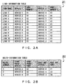
- the network-state displaying device generates a link-information table 201 illustrated in FIG. 2A and holds the table in a memory included in itself.
- Each entry in the link-information table 201 holds, for each link that is indicated by a name held in "LINK NAME” , names and port numbers of devices in "DEVICE 1" and “PORT NUMBER 1", and in "DEVICE 2" and "PORT NUMBER 2", the devices being each connected to the respective ends of the link.
- a first entry in the link-information table 201 defines a state in which Link 1 is formed by connecting a port 102 with number 01 of device 1 and a port 102 with number 01 of device 3.
- second to eleventh entries in the link-information table 201 define Links 2 to 11. Accordingly, the network-state displaying device is able to generate and display drawing data of the network topology in which devices 1 to 8 and servers 1 and 2 are connected to one another through Links 1 to 11, as illustrated in FIG. 1 .
- the network-state displaying device displays, on the network topology, a blue first line that indicates a specific transmission path in the network 100, and a symbol whose display position is dynamically moved in a direction in which data is transmitted through the transmission path.
- the network-state displaying device may individually draw the blue first line and the symbol in different display layers and may display the two layers superimposed over each other.
- the layer is a logical image-drawing area in which one layer has a drawing area for one image.
- the layer is a drawing function that displays an image on a drawing area of each layer so that the images are superimposed over one another, which makes it possible to control display/non-display of an image for each layer and to control which image displayed on the layer is to be displayed above.
- Information on a route established with respect to a transmission path and acquired from a communication device is an example of the information element for which a symbol is displayed.
- the network-state displaying device As the information on a route, the network-state displaying device generates a route-information table 202 illustrated in FIG. 2B and holds the table in a memory included in itself. Each entry in the route-information table 202 holds, for each route that is indicated by a number in "ROUTE NUMBER", names and port numbers of a devices of a start point and a next hop on the route in "START POINT DEVICE" and "START POINT PORT", and in "NEXT HOP DEVICE" and "NEXT HOP PORT".
- a first entry in the route-information table 202 indicates that a route with number 1 is formed from a port with number 02 of server 2 to a port with number 01 of device 8.
- a second entry in the route-information table 202 indicates that a route with number 2 is formed from a port with number 04 of server 8 to a port with number 03 of device 4.
- a third entry in the route-information table 202 indicates that a route with number 3 is formed from a port with number 01 of device 4 to a port with number 04 of device 3.
- the network-state displaying device refers to the link-information table 201 of FIG. 2A using a connection relationship between the port with number 02 of server 2 and the port with number 01 of device 8 that are extracted from the first entry in the route-information table 202, so as to extract Link 11.
- the network-state displaying device displays a symbol 110 (#1) marked with " ⁇ " on a blue first line in Link 11 in the network topology of FIG. 1 , and repeatedly dynamically moves it in a direction of an arrow A (#1) from server 2 to device 8.
- the symbol 110 marked with " ⁇ ” is also used in an area other than the area of the blue first line.
- the network-state displaying device refers to the link-information table 201 of FIG. 2A using a connection relationship between the port with number 04 of device 8 and the port with number 03 of device 4 that are obtained from the second entry in the route-information table 202, so as to extract Link 7.
- the network-state displaying device displays a symbol 110 (#2) marked with " ⁇ " on a blue first line in Link 7 in the network topology of FIG. 1 , and repeatedly dynamically moves it in a direction of an arrow A (#2) from device 8 to device 4.
- the network-state displaying device refers to the link-information table 201 of FIG. 2A using a connection relationship between the port with number 01 of device 4 and the port with number 04 of device 3 that are obtained from the third entry in the route-information table 202, so as to extract Link 5.
- the network-state displaying device 1 displays a symbol 110 (#3) marked with " ⁇ " on a blue first line in Link 5 in the network topology of FIG. 1 , and repeatedly dynamically moves it in a direction of an arrow A (#3) from device 4 to device 3.
- a user such as a network administrator is able to easily recognize that routes are established for Link 11, 7, and 5 by corresponding symbols 110 (#1, #2, and #3) that move dynamically.
- the network-state displaying device displays, on the network topology, a second line superimposed over the above-described display, according to the occurrence of a prescribed event that is detected on the basis of information collected from devices 1 to 8 and servers 1 and 2.
- the second line is drawn on the basis of a different information element than the first line.
- a display state is adjusted such that the symbol is moved in a position or in a size in which at least a portion of the symbol is not hidden under the second line.
- the network-state displaying device may individually draw the first line and the second line in different layers and may display the two layers superimposed over each other. This permits the network-state displaying device to determine which layer is to be preferentially displayed above, the layer on which the first line and the symbol 110 marked with " ⁇ " is displayed, or the layer of the second line, so as to control the display operation.
- Failure information on devices 1 to 8 or servers 1 and 2, or on a transmission path is an example of the above-described information element that corresponds to the occurrence of an event.
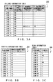
- the network-state displaying device 1 As the failure information, the network-state displaying device 1 generates a failure-information table 203 illustrated in FIG. 3A , and holds the table in a memory included in itself. Each entry in the failure-information table 203 holds "YES” or “NO” in "EXISTENCE/NON-EXISTENCE OF FAILURE" for each route that is indicated by a name in "LINK NAME".
- the table holds, in "FAILURE-OCCURRENCE DEVICE” and "FAILURE-OCCURRENCE PORT NUMBER" in the entry, a name of a device (a communication device 101) in which the failure has occurred and a number of a port in which the failure has occurred.
- a seventh entry in the failure-information table 203 indicates that a failure has occurred in Link 7 and a device in which the failure has occurred and a number of a port in which the failure has occurred are device 4 and number 03, respectively. Entries other than the seventh entry in the failure-information table 203 indicate that a failure has not occurred in links other than Link 7.
- the network-state displaying device displays a red second line 111 (#1) superimposed over a blue first line in Link 7, the red second line 111 (#1) indicating the occurrence of a failure.
- the network-state displaying device displays a pixel in a layer of the red second line 111 (#1) that indicates the occurrence of a failure, giving priority to it over a pixel in a layer of the blue first line that is previously placed in Link 7 on which route information is displayed.
- the network-state displaying device adjusts a display state such that at least a portion of the symbol 110 (#2) marked with " ⁇ ” that moves in a line in Link 7 is not hidden under the read second line 111 (#1) .
- the network-state displaying device draws, in a first layer, the blue first line that is previously placed in Link 7, and displays the red second line 111 (#1) in a second layer.
- a symbol marked with " ⁇ ” may be displayed in the first layer, the second layer, or a layer other than these layers.
- "a layer is displayed” refers to a state in which data corresponding to a layer in a memory is drawn when the data is written in an image memory.
- the network-state displaying device controls such that the second layer is displayed above and the first layer is displayed below. Accordingly, the blue first line that is previously placed is completely hidden under the red second line 111 (#1) that indicates the occurrence of a failure, but the movement of a portion of the symbol 110 (#2) marked with " ⁇ " that is not hidden under the red second line 111 (#1) can be found out.
- Information on an amount of traffic in a transmission path is another example of the above-described information element that corresponds to the occurrence of an event.
- the network-state displaying device generates a traffic-information table 204 illustrated in FIG. 3B , and holds the table in a memory included in itself. For each link that is indicated by a name held in "LINK NAME", each entry in the traffic-information table 204 holds, in "TRAFFIC USAGE RATE (%) ", a usage rate with respect to a maximum capacity of traffic in the transmission path. For example, a first entry in the traffic-information table 204 indicates that a usage rate in Link 1 is 90 %. Likewise, second entry to eleventh entries in the traffic-information table 204 hold usage rates in Link 2 to Link 11, respectively.
- the network-state displaying device displays, on the network topology, a green second line 112 (#1) superimposed over a line in Link 1, the green second line 112 (#1) indicating that the amount of traffic is about to reach a limit. Also in this case, a symbol marked with " ⁇ " can also be used when route information has to be displayed on Link 1.
- information on a virtual network including a transmission path is another example of the above-described information element that corresponds to the occurrence of an event.
- the network-state displaying device generates a VLAN (virtual local area network) -information table 205 illustrated in FIG. 3C , and holds the table in a memory included in itself. For each link that is indicated by a name held in "LINK NAME”, each entry in the VLAN-information table 205 holds, in "VLAN ID", a VLAN ID that is equal to or more than zero (virtual network identifier) to which the link belongs.
- VLAN virtual local area network
- the network-state displaying device displays, on the network topology, a purple second line 113 (#1) superimposed over a line in Link 2, the purple second line 113 (#1) indicating that a VLAN ID is allocated. Further, the network-state displaying device displays, on the network topology, a purple second line 113 (#2) superimposed over a line in Link 5, the purple second line 113 (#2) indicating that a VLAN ID is allocated.
- the network-state displaying device 1 refers to an information-element displaying priority table 207 illustrated in FIG. 4B that will be described below, and thereby recognizes that an information element for a virtual network is given priority for display over an information element for a route.
- the network-state displaying device 1 displays a pixel in a layer of the purple second line 113 (#1) that indicates a virtual network, giving priority to it over a pixel in a layer of the blue first line that is previously placed in Link 5 on which route information is displayed.
- the network-state displaying device 1 adjusts a display state such that at least a portion of the symbol 110 (#3) marked with " ⁇ ” that moves in a line in Link 5 is not hidden under the purple second line 113 (#2) .
- the network-state displaying device 1 draws, in a first layer, the blue first line that is previously placed in Link 5, and displays the purple second line 113 (#2) in a second layer.
- a symbol marked with " ⁇ " (#3) is displayed on the first layer, the second layer, or a layer other than these layers. Then, the network-state displaying device 1 controls such that the second layer is displayed above and the first layer is displayed below.
- the blue first line that is previously placed is completely hidden under the purple second line 113 (#2) that indicates a virtual network, but the movement of a portion of the symbol 110 (#3) marked with " ⁇ " that is not hidden under the purple second line 113 (#2) can be found out.
- the number of the above-described information elements to be displayed that correspond to the occurrence of an event is not limited to one with respect to an information element, for example route information, for which a symbol is displayed, but a plurality of types of second lines that indicate information elements such as failure information, traffic information, and VLAN information may be displayed in a superimposed state.
- the network-state displaying device adjusts a display state such that a symbol moves in a position or in a size in which at least a portion of the symbol is not hidden under the second lines.
- the network-state displaying device refers to an information-element representing method table 206 illustrated in FIG.
- the attributes 4A that will be described below using the above-described information element corresponding to the occurrence of an event, and thereby changes the attributes of a second line in a corresponding entry, the attributes including a color, a thickness, a blinking state, and a type.
- FIG. 4A illustrates an example of a data structure of the information-element representing method table 206 which the network-state displaying device holds in a memory included in itself.
- Each entry in the information-element representing method table 206 holds, for each information element registered in "TYPE OF INFORMATION ELEMENT", pieces of attribute information on a thickness, a color, and blinking/non-blinking of a link to be displayed in "THICKNESS OF LINK", “COLOR OF LINK”, and “BLINKING/NON-BLINKING OF LINK”, respectively.
- each entry holds pieces of attribute information on a form and blinking/non-blinking of a symbol to be displayed in "FORM OF SYMBOL" and "BLINKING/NON-BLINKING OF SYMBOL", respectively.
- the network-state displaying device refers to the information-element representing method table 206 when it displays a first line, a symbol, or a second line that corresponds to one of the information elements including route information, failure information, information indicating a traffic state, and VLAN information described above. As a result, for each information element, the network-state displaying device determines an attribute of a line or symbol to be displayed to perform a display.
- the information-element representing method table 206 can also be configured to be provided for each authority of a user or for each network administration.
- the network-state displaying device may refer to a corresponding information-element representing method table 206 for each authority of a user or for each network administration, and may control the display that corresponds to each information element and in which a line or a symbol is used. This makes it possible to customize each of the attributes of the symbol, the first line, and the second line described above for each authority of a user or for each network administration.
- FIG. 4B illustrates an example of a data structure of the information-element displaying priority table 207 which the network-state displaying device holds in a memory included in itself.
- Each entry in the information-element displaying priority table 207 holds, for each information element registered in "TYPE OF INFORMATION ELEMENT", a value corresponding to an order of priority in "PRIORITY". An information element with a smaller value is given a higher priority.
- the network-state displaying device refers to the information-element displaying priority table 207, so as to determine a priority for a display of symbol/line and to perform a control. In this case, an information element with a smaller number for an order of priority, that is, an information element given a higher priority is displayed on a layer above.
- the information-element displaying priority table 207 can also be configured to be provided for each authority of a user or for each network administration.
- the network-state displaying device refers to a corresponding information-element displaying priority table 207 for each authority of a user or for each network administration, and determines a priority for a display of symbol/line to perform a control. This makes it possible to customize a priority when displaying the first symbol, the second symbol, the first line, and the second line described above superimposed over one another for each authority of a user or for each network administration.
- FIG. 5 is a flowchart that illustrates an example of network-state displaying processing performed by the network-state displaying device of FIG. 1 .
- the network-state displaying device generates the link-information table 201 illustrated in FIG. 2A described above on the basis of the information collected from each communication device 101 (devices 1 to 8 and servers 1 and 2) . Then, as described above, the network-state displaying device refers to the link-information table 201, so as to generate data of a network topology and to perform a display, in the form of a diagram illustrated in FIG. 1 (Step S501).
- the network-state displaying device waits until it receives a request for displaying an information element on a link (a line) as a request issued by a GUI manipulated by a user or as a request issued by a determination in a system (it is repeatedly determined to be NO in Step S502).
- the network-state displaying device determines an information element to be displayed on a link.
- the information element one or more information elements are selected from the route information, the failure information, the traffic information, and the VLAN information described above (Step S503).
- the network-state displaying device refers to the route-information table 202 ( FIG. 2B ), the failure-information table 203 ( FIG. 3A ), the traffic-information table 204 ( FIG. 3B ), or the VLAN-information table 205 ( FIG. 3C ) described above.
- the network-state displaying device thereby acquires data corresponding to the above information element from each of the tables, as described above (Step S504).
- the network-state displaying device determines a link (a link name) on which an information element is to be displayed following the data acquisition in Step S504 (Step S505).
- the network-state displaying device refers to the information-element representing method table 206 of FIG. 4A , so as to determine a method for displaying an information element to be displayed (Step S506).
- the network-state displaying device refers to the information-element displaying priority table 207 of FIG. 4B , so as to determine a priority for a display of an information element (Step S507).
- the network-state displaying device displays, on the link determined in Step S505, all the designated information elements superimposed over one another (Step S508).
- the network-state displaying device terminates the network-state displaying processing.
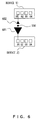
- FIG. 6 illustrates another example of displaying a symbol.
- an amount of traffic is represented by the size of a symbol, like 601 or 602.
- a larger amount of traffic data traffic
- an amount of transmission data and an amount of reception data are included in an amount of traffic for each port of a network device, so the amount of transmission data and the amount of reception data can also be individually confirmed if the directions of the movements of the symbols for transmission and reception are represented in opposite directions, like 601 and 602.
- FIG. 7 illustrates yet another example of displaying a symbol.
- VLAN information in order to represent a VLAN ID, not only a second line but also another symbol that is different from a moving symbol indicating route information is further displayed with respect to an information element determined according to the occurrence of an event that indicates VLAN information.
- FIG. 7 when VLAN information is represented in a link such as Link 1-1, Link 1-2, Link 2, Link 3-1, or Link 3-2, a number of a VLAN ID is added to a symbol 701 (#1 to #5).
- FIG. 1 it is not possible to identify a VLAN ID just by seeing a purple second line 113 indicating VLAN information, but it is possible to identify a VLAN ID using the representation of FIG. 7 .
- the route of VLAN 10 is "port with number 01 of device 12 ⁇ port with number 01 of device 10 ⁇ port with number 04 of device 10 ⁇ port with number 01 of device 11 ⁇ port with number 02 of device 11 ⁇ port with number 02 of device 13".
- the route of VLAN 20 is "port with number 02 of device 12 ⁇ port with number 02 of device 10 ⁇ port with number 04 of device 10 ⁇ port with number 01 of device 11 ⁇ port with number 04 of device 11 ⁇ port with number 04 of device 13". It is possible to recognize that the route from the port with number 04 of device 10 to the port with number 01 of device 11 is a route through which both VLAN 10 and VLAN 20 pass.
- a VLAN ID can also be recognized when a symbol represented in this way and another symbol are used together.
- FIG. 8 illustrates examples of GUIs that designate a display/non-display of an information element.
- a setting screen of a GUI 801 whether a line reporting failure information is to be displayed on a screen of the network topology of FIG. 1 , and whether blinking for the report is to be performed are selected.
- a setting screen of a GUI 802 whether a line indicating a setting state of a VLAN is to be displayed on the screen of the network topology of FIG. 1 is selected.
- Using a setting screen of a GUI 803 whether route information is to be displayed on the screen of the network topology of FIG. 1 is selected.
- a setting screen of a GUI 804 whether a traffic state is to be displayed on the screen of the network topology of FIG. 1 is selected.
- FIG. 9 illustrates an example of a hardware configuration of a computer, by which the network-state displaying device 1 of the embodiment can be realized.
- the computer of FIG. 9 has a CPU 1001, a memory 1002, an input device 1003, an output device 1004, an external storage 1005, a portable-recording-medium driving device 1006 into which a portable recording medium 1009 is inserted, and a communication interface 1007 that are connected to one another through a bus 1008.
- the configuration illustrated in FIG. 9 is an example of a computer by which the system described above can be realized, but the configuration of such a computer is not limited to this configuration.
- the CPU 1001 controls the overall computer.
- the memory 1002 is a memory such as a RAM that temporality stores therein a program or data stored in the external storage 1005 (or the portable recording medium 1009), for example, when the program is executed or when the data is updated.
- the CPU 1001 reads out a program into the memory 1002 and executes it, so as to perform a total control.
- the memory 1002 stores therein the link-information table 201 ( FIG. 2A ), the route-information table 202 ( FIG. 2B ), the failure-information table 203 ( FIG. 3A ), the traffic-information table 204 ( FIG. 3B ), or the VLAN-information table 205 ( FIG. 3C ).
- the input device 1003 detects an input manipulation performed by a user using, for example, a keyboard or a mouse, and reports a result of the detection to the CPU 1001.
- the output device 1004 outputs, to a display device or a printer, data that is transmitted due to a control performed by the CPU 1001.
- the output device 1004 according to the present embodiment includes a display device that displays the network topology of FIG. 1 or the information elements of FIG. 6 or 7 , or that displays the GUI setting screens of FIG. 8 .
- the external storage 1005 is, for example, a hard disk storage device. It is mainly used for storing various pieces of data or programs.
- the portable-recording-medium driving device 1006 accepts a portable recording medium 1009 such as an SD card, a compact flash, a CD-ROM, a DVD, or an optical disk, and serves as an auxiliary device of the external storage 1005.
- a portable recording medium 1009 such as an SD card, a compact flash, a CD-ROM, a DVD, or an optical disk
- the communication interface 1007 is a device for connecting a communication line such as a LAN (local area network) or a WAN (wide area network), and includes a function for connecting to the network 100 ( FIG. 1 ).
- the system according to the present embodiment is realized by the CPU 1001 executing a program of network-state displaying processing that is provided with a network-state displaying function realized by, for example, the flowchart of FIG. 5 .
- the program may be stored in, for example, the external storage 1005 or the portable recording medium 1009 and may be distributed from it, or a configuration in which the program can be acquired from a network through the communication interface 1007 may be provided.
Landscapes
- Engineering & Computer Science (AREA)
- Computer Networks & Wireless Communication (AREA)
- Signal Processing (AREA)
- Human Computer Interaction (AREA)
- Data Mining & Analysis (AREA)
- Physics & Mathematics (AREA)
- General Physics & Mathematics (AREA)
- Theoretical Computer Science (AREA)
- Data Exchanges In Wide-Area Networks (AREA)
- Computer And Data Communications (AREA)
- Maintenance And Management Of Digital Transmission (AREA)
- User Interface Of Digital Computer (AREA)
Abstract
Description
- The embodiments discussed herein are related to a display method and device for displaying a state of a network on the basis of an information element collected from a communication device included in the network.
- As a network managing system introduced to an enterprise, a system in which a network topology is represented by use of a graphical user interface (GUI) is known. In such a system, a network configuration is visualized, and displays of, for example, settings for a communication device included in a network and a failure that has occurred in the communication device are realized.
- In a network topology provided by a GUI, a transmission path that connects communication devices is represented by one link (line) that connects ports of the respective communication devices, in order to faithfully represent a physical connection between communication devices. In this case, the network topology is used not only for visualizing a physical structure, but also for visualizing a logical structure between communication devices, as described below. The network topology is used for the purpose of reporting an information element obtained as a result of introducing or referring to network settings by a user initiation, an information element on a network failure that occurs irregularly, or an information element on an amount of traffic in a transmission path.
- With respect to a display of a network state, the following conventional technology is known (see, for example, Patent Document 1). Means for generating traffic display data uses display data that indicates connection states of a node and a link that are included in an information network, and an amount of transmission information detected between reported nodes for each different transmission direction. Then, the means for generating traffic display data generates pieces of display data that indicate an information transmission direction for each link and an amount of information in the transmission direction. These pieces of display data are displayed on display means.
Patent Document 1:Japanese Laid-open Patent Publication No. 05-158878 - In one aspect, an object of the present invention is to make it possible to display, in an easily identifiable state, a plurality of information elements that indicate a state of a network.
- A display method according to an aspect displays a state of a network on the basis of information collected from a communication device included in the network. The display method displays a first line that indicates a specific transmission path in the network and a symbol whose display position is dynamically moved in a direction in which data is transmitted through the transmission path, displays, on a layer that is located above a layer on which the first line is displayed, a second line superimposed over the first line and the symbol, according to the occurrence of a prescribed event that is detected on the basis of the collected information, wherein the second line has an overlapping portion with the first line, and moves the symbol in a position or in a size in which at least a portion of the symbol is not hidden under the second line.
-
-
FIG. 1 is a diagram according to an embodiment of the present invention; -
FIGs. 2A and 2B illustrate examples of data structures of tables used in the embodiment (1); -
FIGs. 3A-3C illustrate examples of data structures of tables used in the embodiment (2); -
FIGs. 4A and 4B illustrate examples of data structures of tables used in the embodiment (3); -
FIG. 5 is a flowchart that illustrates an example of processing according to the embodiment; -
FIG. 6 illustrates another example of displaying a symbol; -
FIG. 7 illustrates yet another example of displaying a symbol; -
FIG. 8 illustrates examples of GUIs that designate a display/non-display of an information element; and -
FIG. 9 is a diagram that illustrates an example of a hardware configuration by which the embodiment can be realized. - However, a link includes various information elements described above, so it is difficult to display a plurality of pieces of information on a state of network settings, a network failure, and an amount of traffic in one line such that a user can identify easily.
- Further, in the conventional technology described above, only a single information element is displayed in an easily identifiable manner, and it is not possible to display a plurality of information elements such that a user can identify easily.
- An object of the present invention is to make it possible to display, in an easily identifiable state, a plurality of information elements that indicate a state of a network.
- Embodiments of the present invention will now be described in detail with reference to the drawings.
FIG. 1 is a diagram of a network topology displayed on a network-state displaying device (not shown) according to an embodiment of the present invention (hereinafter referred to as a "present embodiment") . Anetwork 100 corresponding to the network topology has a configuration in whichcommunication devices 101 are connected to one another through a transmission path. The network-state displaying device collects information from eachcommunication device 101. - According to the present embodiment, for example,
devices 1 to 8 andservers devices 1 to 8 andservers communication devices 101 are connected to one another through a transmission path, which forms the configuration of thenetwork 100. A server computer is an example ofservers devices 1 to 8. - Each
communication device 101 includesports 102 indicated as a port number such as "01", "02" , "03", and "04" (fordevices 1 to 8), or "01" and "02" (forservers 1 and 2). - One of the
ports 102 of acommunication device 101 is connected to one of theports 102 of anothercommunication device 101 through a transmission path (including a wireless one), which forms, between thecommunication devices 101, a physical link indicated as one ofLinks 1 to 11. - The network-state displaying device (not shown) is a management terminal, which performs network-state displaying processing by executing, using a CPU (central processing unit) included in itself, a network-state displaying program stored in a memory included in itself.
- As a basic operation, the network-state displaying device generates data of a network topology on the basis of information collected from each communication device 101 (
devices 1 to 8 andservers 1 and 2) and displays the data. As illustrated inFIG. 1 , the network topology is a diagram in whichdevices 1 to 8 andservers network 100 are connected to one another throughLinks 1 to 11. - In order to generate a network topology, the network-state displaying device collects connection-destination information for each
port 102 from each of the communication devices 101 (hereinafter referred to as a "device") that aredevices 1 to 8 andservers FIG. 2A and holds the table in a memory included in itself. Each entry in the link-information table 201 holds, for each link that is indicated by a name held in "LINK NAME" , names and port numbers of devices in "DEVICE 1" and "PORT NUMBER 1", and in "DEVICE 2" and "PORT NUMBER 2", the devices being each connected to the respective ends of the link. For example, a first entry in the link-information table 201 defines a state in whichLink 1 is formed by connecting aport 102 withnumber 01 ofdevice 1 and aport 102 withnumber 01 ofdevice 3. Likewise, second to eleventh entries in the link-information table 201 defineLinks 2 to 11. Accordingly, the network-state displaying device is able to generate and display drawing data of the network topology in whichdevices 1 to 8 andservers Links 1 to 11, as illustrated inFIG. 1 . - The network-state displaying device displays, on the network topology, a blue first line that indicates a specific transmission path in the
network 100, and a symbol whose display position is dynamically moved in a direction in which data is transmitted through the transmission path. In this case, for example, the network-state displaying device may individually draw the blue first line and the symbol in different display layers and may display the two layers superimposed over each other. - In this case, the layer is a logical image-drawing area in which one layer has a drawing area for one image. The layer is a drawing function that displays an image on a drawing area of each layer so that the images are superimposed over one another, which makes it possible to control display/non-display of an image for each layer and to control which image displayed on the layer is to be displayed above.
- Information on a route established with respect to a transmission path and acquired from a communication device is an example of the information element for which a symbol is displayed. As the information on a route, the network-state displaying device generates a route-information table 202 illustrated in
FIG. 2B and holds the table in a memory included in itself. Each entry in the route-information table 202 holds, for each route that is indicated by a number in "ROUTE NUMBER", names and port numbers of a devices of a start point and a next hop on the route in "START POINT DEVICE" and "START POINT PORT", and in "NEXT HOP DEVICE" and "NEXT HOP PORT". For example, a first entry in the route-information table 202 indicates that a route withnumber 1 is formed from a port withnumber 02 ofserver 2 to a port withnumber 01 ofdevice 8. Likewise, for example, a second entry in the route-information table 202 indicates that a route withnumber 2 is formed from a port withnumber 04 ofserver 8 to a port withnumber 03 ofdevice 4. Further, likewise, for example, a third entry in the route-information table 202 indicates that a route withnumber 3 is formed from a port withnumber 01 ofdevice 4 to a port withnumber 04 ofdevice 3. - The network-state displaying device refers to the link-information table 201 of
FIG. 2A using a connection relationship between the port withnumber 02 ofserver 2 and the port withnumber 01 ofdevice 8 that are extracted from the first entry in the route-information table 202, so as to extractLink 11. As a result, the network-state displaying device displays a symbol 110 (#1) marked with "●" on a blue first line inLink 11 in the network topology ofFIG. 1 , and repeatedly dynamically moves it in a direction of an arrow A (#1) fromserver 2 todevice 8. Thesymbol 110 marked with "●" is also used in an area other than the area of the blue first line. - Likewise, the network-state displaying device refers to the link-information table 201 of
FIG. 2A using a connection relationship between the port withnumber 04 ofdevice 8 and the port withnumber 03 ofdevice 4 that are obtained from the second entry in the route-information table 202, so as to extractLink 7. As a result, the network-state displaying device displays a symbol 110 (#2) marked with "●" on a blue first line inLink 7 in the network topology ofFIG. 1 , and repeatedly dynamically moves it in a direction of an arrow A (#2) fromdevice 8 todevice 4. - Further, the network-state displaying device refers to the link-information table 201 of
FIG. 2A using a connection relationship between the port withnumber 01 ofdevice 4 and the port withnumber 04 ofdevice 3 that are obtained from the third entry in the route-information table 202, so as to extractLink 5. As a result, the network-state displaying device 1 displays a symbol 110 (#3) marked with "●" on a blue first line inLink 5 in the network topology ofFIG. 1 , and repeatedly dynamically moves it in a direction of an arrow A (#3) fromdevice 4 todevice 3. - In this way, a user such as a network administrator is able to easily recognize that routes are established for
Link - Next, the network-state displaying device displays, on the network topology, a second line superimposed over the above-described display, according to the occurrence of a prescribed event that is detected on the basis of information collected from
devices 1 to 8 andservers symbol 110 marked with "●" is displayed, or the layer of the second line, so as to control the display operation. - Failure information on
devices 1 to 8 orservers state displaying device 1 generates a failure-information table 203 illustrated inFIG. 3A , and holds the table in a memory included in itself. Each entry in the failure-information table 203 holds "YES" or "NO" in "EXISTENCE/NON-EXISTENCE OF FAILURE" for each route that is indicated by a name in "LINK NAME". Further, when there exists a failure, the table holds, in "FAILURE-OCCURRENCE DEVICE" and "FAILURE-OCCURRENCE PORT NUMBER" in the entry, a name of a device (a communication device 101) in which the failure has occurred and a number of a port in which the failure has occurred. For example, a seventh entry in the failure-information table 203 indicates that a failure has occurred inLink 7 and a device in which the failure has occurred and a number of a port in which the failure has occurred aredevice 4 andnumber 03, respectively. Entries other than the seventh entry in the failure-information table 203 indicate that a failure has not occurred in links other thanLink 7. - According to the information that "EXISTENCE/NON-EXISTENCE OF FAILURE"="YES" in
Link 7 which is extracted from the seventh entry in the network-state displaying device 203, the network-state displaying device displays a red second line 111 (#1) superimposed over a blue first line inLink 7, the red second line 111 (#1) indicating the occurrence of a failure. The network-state displaying device displays a pixel in a layer of the red second line 111 (#1) that indicates the occurrence of a failure, giving priority to it over a pixel in a layer of the blue first line that is previously placed inLink 7 on which route information is displayed. - In this case, as illustrated in
FIG. 1 , the network-state displaying device adjusts a display state such that at least a portion of the symbol 110 (#2) marked with "●" that moves in a line inLink 7 is not hidden under the read second line 111 (#1) . For example, the network-state displaying device draws, in a first layer, the blue first line that is previously placed inLink 7, and displays the red second line 111 (#1) in a second layer. A symbol marked with "●" may be displayed in the first layer, the second layer, or a layer other than these layers. Here, "a layer is displayed" refers to a state in which data corresponding to a layer in a memory is drawn when the data is written in an image memory. Then, the network-state displaying device controls such that the second layer is displayed above and the first layer is displayed below. Accordingly, the blue first line that is previously placed is completely hidden under the red second line 111 (#1) that indicates the occurrence of a failure, but the movement of a portion of the symbol 110 (#2) marked with "●" that is not hidden under the red second line 111 (#1) can be found out. - As described above, according to the present embodiment, even when there are a plurality of information elements to be displayed with respect to one transmission path, these information elements can be displayed together at a time in a state in which each of them is identifiable. In the example described above, it is possible to find out a route from the symbol 110 (#2) marked with "●" that moves in the line in
Link 7, and it is possible to easily find out from the red second line 111 (#1) that a failure has occurred with respect toLink 7. - Information on an amount of traffic in a transmission path is another example of the above-described information element that corresponds to the occurrence of an event. As the information on an amount of traffic, the network-state displaying device generates a traffic-information table 204 illustrated in
FIG. 3B , and holds the table in a memory included in itself. For each link that is indicated by a name held in "LINK NAME", each entry in the traffic-information table 204 holds, in "TRAFFIC USAGE RATE (%) ", a usage rate with respect to a maximum capacity of traffic in the transmission path. For example, a first entry in the traffic-information table 204 indicates that a usage rate inLink 1 is 90 %. Likewise, second entry to eleventh entries in the traffic-information table 204 hold usage rates inLink 2 to Link 11, respectively. - The network-state displaying device extracts a link name from "LINK NAME" in an entry that satisfies a prescribed condition and that is included in the entries in the traffic-information table 204. Then, the network-state displaying device displays, on the network topology, a green second line superimposed over a line corresponding to the link name, the green second line indicating a traffic state. For example, in the traffic-information table 204 illustrated in
FIG. 3B , the network-state displaying device extracts a link name=Link 1 from "LINK NAME" in an entry in which a usage rate is not less than a prescribed threshold, for example, not less than 90 %. Then, the network-state displaying device displays, on the network topology, a green second line 112 (#1) superimposed over a line inLink 1, the green second line 112 (#1) indicating that the amount of traffic is about to reach a limit. Also in this case, a symbol marked with "●" can also be used when route information has to be displayed onLink 1. - Further, information on a virtual network including a transmission path is another example of the above-described information element that corresponds to the occurrence of an event. As the information on a virtual network, the network-state displaying device generates a VLAN (virtual local area network) -information table 205 illustrated in
FIG. 3C , and holds the table in a memory included in itself. For each link that is indicated by a name held in "LINK NAME", each entry in the VLAN-information table 205 holds, in "VLAN ID", a VLAN ID that is equal to or more than zero (virtual network identifier) to which the link belongs. For example, a second entry in the VLAN-information table 205 indicates that VLAN ID=100 is allocated toLink 2, and likewise, a fifth entry indicates that VLAN ID=100 is allocated toLink 5. Other entries indicate that VLAN ID=1 that is a default is allocated to links other thanLink 2 andLink 5. - The network-state displaying device extracts a link name from "LINK NAME" in an entry to which a VLAN ID other than VLAN ID=1 is allocated and that is included in the entries in the VLAN-information table 205. Then, the network-state displaying device displays, on the network topology, a purple second line superimposed over a line corresponding to the link name, the purple second line indicating that a VLAN ID is allocated. For example, in the VLAN-information table 205 illustrated in
FIG. 3C , the network-state displaying device extracts link names=Link 2 andLink 5 from "LINK NAME" in entries to which a VLAN ID other than VLAN ID=1 is allocated. A user may designate a VLAN ID to be displayed on a screen using a GUI. Then, the network-state displaying device displays, on the network topology, a purple second line 113 (#1) superimposed over a line inLink 2, the purple second line 113 (#1) indicating that a VLAN ID is allocated. Further, the network-state displaying device displays, on the network topology, a purple second line 113 (#2) superimposed over a line inLink 5, the purple second line 113 (#2) indicating that a VLAN ID is allocated. In this case, the network-state displaying device 1 refers to an information-element displaying priority table 207 illustrated inFIG. 4B that will be described below, and thereby recognizes that an information element for a virtual network is given priority for display over an information element for a route. Accordingly, the network-state displaying device 1 displays a pixel in a layer of the purple second line 113 (#1) that indicates a virtual network, giving priority to it over a pixel in a layer of the blue first line that is previously placed inLink 5 on which route information is displayed. - In this case, as illustrated in
FIG. 1 , with respect toLink 5, the network-state displaying device 1 adjusts a display state such that at least a portion of the symbol 110 (#3) marked with "●" that moves in a line inLink 5 is not hidden under the purple second line 113 (#2) . For example, the network-state displaying device 1 draws, in a first layer, the blue first line that is previously placed inLink 5, and displays the purple second line 113 (#2) in a second layer. A symbol marked with "●" (#3) is displayed on the first layer, the second layer, or a layer other than these layers. Then, the network-state displaying device 1 controls such that the second layer is displayed above and the first layer is displayed below. Accordingly, the blue first line that is previously placed is completely hidden under the purple second line 113 (#2) that indicates a virtual network, but the movement of a portion of the symbol 110 (#3) marked with "●" that is not hidden under the purple second line 113 (#2) can be found out. - As described above, it is possible to find out a route from the symbol 110 (#3) marked with "●" that moves in the line in
Link 5, and it is possible to easily find out from the purple second line 113 (#2) that a virtual network is established with respect toLink 5. - The number of the above-described information elements to be displayed that correspond to the occurrence of an event is not limited to one with respect to an information element, for example route information, for which a symbol is displayed, but a plurality of types of second lines that indicate information elements such as failure information, traffic information, and VLAN information may be displayed in a superimposed state. In this case, the network-state displaying device adjusts a display state such that a symbol moves in a position or in a size in which at least a portion of the symbol is not hidden under the second lines. Specifically, the network-state displaying device refers to an information-element representing method table 206 illustrated in
FIG. 4A that will be described below using the above-described information element corresponding to the occurrence of an event, and thereby changes the attributes of a second line in a corresponding entry, the attributes including a color, a thickness, a blinking state, and a type. -
FIG. 4A illustrates an example of a data structure of the information-element representing method table 206 which the network-state displaying device holds in a memory included in itself. Each entry in the information-element representing method table 206 holds, for each information element registered in "TYPE OF INFORMATION ELEMENT", pieces of attribute information on a thickness, a color, and blinking/non-blinking of a link to be displayed in "THICKNESS OF LINK", "COLOR OF LINK", and "BLINKING/NON-BLINKING OF LINK", respectively. Further, each entry holds pieces of attribute information on a form and blinking/non-blinking of a symbol to be displayed in "FORM OF SYMBOL" and "BLINKING/NON-BLINKING OF SYMBOL", respectively. The network-state displaying device refers to the information-element representing method table 206 when it displays a first line, a symbol, or a second line that corresponds to one of the information elements including route information, failure information, information indicating a traffic state, and VLAN information described above. As a result, for each information element, the network-state displaying device determines an attribute of a line or symbol to be displayed to perform a display. - The information-element representing method table 206 can also be configured to be provided for each authority of a user or for each network administration. In this case, the network-state displaying device may refer to a corresponding information-element representing method table 206 for each authority of a user or for each network administration, and may control the display that corresponds to each information element and in which a line or a symbol is used. This makes it possible to customize each of the attributes of the symbol, the first line, and the second line described above for each authority of a user or for each network administration.
-
FIG. 4B illustrates an example of a data structure of the information-element displaying priority table 207 which the network-state displaying device holds in a memory included in itself. Each entry in the information-element displaying priority table 207 holds, for each information element registered in "TYPE OF INFORMATION ELEMENT", a value corresponding to an order of priority in "PRIORITY". An information element with a smaller value is given a higher priority. The network-state displaying device refers to the information-element displaying priority table 207, so as to determine a priority for a display of symbol/line and to perform a control. In this case, an information element with a smaller number for an order of priority, that is, an information element given a higher priority is displayed on a layer above. - The information-element displaying priority table 207 can also be configured to be provided for each authority of a user or for each network administration. In this case, the network-state displaying device refers to a corresponding information-element displaying priority table 207 for each authority of a user or for each network administration, and determines a priority for a display of symbol/line to perform a control. This makes it possible to customize a priority when displaying the first symbol, the second symbol, the first line, and the second line described above superimposed over one another for each authority of a user or for each network administration.
-
FIG. 5 is a flowchart that illustrates an example of network-state displaying processing performed by the network-state displaying device ofFIG. 1 . - First, the network-state displaying device generates the link-information table 201 illustrated in
FIG. 2A described above on the basis of the information collected from each communication device 101 (devices 1 to 8 andservers 1 and 2) . Then, as described above, the network-state displaying device refers to the link-information table 201, so as to generate data of a network topology and to perform a display, in the form of a diagram illustrated inFIG. 1 (Step S501). - Next, the network-state displaying device waits until it receives a request for displaying an information element on a link (a line) as a request issued by a GUI manipulated by a user or as a request issued by a determination in a system (it is repeatedly determined to be NO in Step S502).
- When it is determined to be YES in Step S502, the network-state displaying device determines an information element to be displayed on a link. With respect to the information element, one or more information elements are selected from the route information, the failure information, the traffic information, and the VLAN information described above (Step S503).
- Next, the network-state displaying device refers to the route-information table 202 (
FIG. 2B ), the failure-information table 203 (FIG. 3A ), the traffic-information table 204 (FIG. 3B ), or the VLAN-information table 205 (FIG. 3C ) described above. The network-state displaying device thereby acquires data corresponding to the above information element from each of the tables, as described above (Step S504). - In addition, as described above, the network-state displaying device determines a link (a link name) on which an information element is to be displayed following the data acquisition in Step S504 (Step S505).
- Further, as described above, the network-state displaying device refers to the information-element representing method table 206 of
FIG. 4A , so as to determine a method for displaying an information element to be displayed (Step S506). - Furthermore, as described above, the network-state displaying device refers to the information-element displaying priority table 207 of
FIG. 4B , so as to determine a priority for a display of an information element (Step S507). - Finally, the network-state displaying device displays, on the link determined in Step S505, all the designated information elements superimposed over one another (Step S508).
- At this point, the network-state displaying device terminates the network-state displaying processing.
-
FIG. 6 illustrates another example of displaying a symbol. In this example, in order to represent an amount of traffic in a link, not only a second line but also another symbol that is different from a movingsymbol 110 indicating route information is further displayed with respect to an information element determined according to the occurrence of an event that indicates a traffic state. InFIG. 6 , an amount of traffic is represented by the size of a symbol, like 601 or 602. For example, a larger amount of traffic (data traffic) flows through a larger symbol betweendevice 1 anddevice 2. Using such a representation, an amount of traffic can be confirmed at a glance even when a symbol is superimposed over another information element. Further, an amount of transmission data and an amount of reception data are included in an amount of traffic for each port of a network device, so the amount of transmission data and the amount of reception data can also be individually confirmed if the directions of the movements of the symbols for transmission and reception are represented in opposite directions, like 601 and 602. -
FIG. 7 illustrates yet another example of displaying a symbol. In this example, in order to represent a VLAN ID, not only a second line but also another symbol that is different from a moving symbol indicating route information is further displayed with respect to an information element determined according to the occurrence of an event that indicates VLAN information. InFIG. 7 , when VLAN information is represented in a link such as Link 1-1, Link 1-2,Link 2, Link 3-1, or Link 3-2, a number of a VLAN ID is added to a symbol 701 (#1 to #5). In the example ofFIG. 1 , it is not possible to identify a VLAN ID just by seeing a purplesecond line 113 indicating VLAN information, but it is possible to identify a VLAN ID using the representation ofFIG. 7 . In this case, the direction of a data flow does not have to be represented in the VLAN information. In the example ofFIG. 7 , the route ofVLAN 10 is "port withnumber 01 ofdevice 12→port withnumber 01 ofdevice 10→port withnumber 04 ofdevice 10→port withnumber 01 ofdevice 11→port withnumber 02 ofdevice 11→port withnumber 02 ofdevice 13". On the other hand, the route ofVLAN 20 is "port withnumber 02 ofdevice 12→port withnumber 02 ofdevice 10 →port withnumber 04 ofdevice 10→port withnumber 01 ofdevice 11→port withnumber 04 ofdevice 11→port withnumber 04 ofdevice 13". It is possible to recognize that the route from the port withnumber 04 ofdevice 10 to the port withnumber 01 ofdevice 11 is a route through which bothVLAN 10 andVLAN 20 pass. A VLAN ID can also be recognized when a symbol represented in this way and another symbol are used together. -
FIG. 8 illustrates examples of GUIs that designate a display/non-display of an information element. Using a setting screen of aGUI 801, whether a line reporting failure information is to be displayed on a screen of the network topology ofFIG. 1 , and whether blinking for the report is to be performed are selected. Using a setting screen of aGUI 802, whether a line indicating a setting state of a VLAN is to be displayed on the screen of the network topology ofFIG. 1 is selected. Using a setting screen of aGUI 803, whether route information is to be displayed on the screen of the network topology ofFIG. 1 is selected. Using a setting screen of aGUI 804, whether a traffic state is to be displayed on the screen of the network topology ofFIG. 1 is selected. -
FIG. 9 illustrates an example of a hardware configuration of a computer, by which the network-state displaying device 1 of the embodiment can be realized. The computer ofFIG. 9 has aCPU 1001, amemory 1002, aninput device 1003, anoutput device 1004, anexternal storage 1005, a portable-recording-medium driving device 1006 into which aportable recording medium 1009 is inserted, and acommunication interface 1007 that are connected to one another through abus 1008. The configuration illustrated inFIG. 9 is an example of a computer by which the system described above can be realized, but the configuration of such a computer is not limited to this configuration. - The
CPU 1001 controls the overall computer. Thememory 1002 is a memory such as a RAM that temporality stores therein a program or data stored in the external storage 1005 (or the portable recording medium 1009), for example, when the program is executed or when the data is updated. TheCPU 1001 reads out a program into thememory 1002 and executes it, so as to perform a total control. In the present embodiment, thememory 1002 stores therein the link-information table 201 (FIG. 2A ), the route-information table 202 (FIG. 2B ), the failure-information table 203 (FIG. 3A ), the traffic-information table 204 (FIG. 3B ), or the VLAN-information table 205 (FIG. 3C ). - The
input device 1003 detects an input manipulation performed by a user using, for example, a keyboard or a mouse, and reports a result of the detection to theCPU 1001. - The
output device 1004 outputs, to a display device or a printer, data that is transmitted due to a control performed by theCPU 1001. Theoutput device 1004 according to the present embodiment includes a display device that displays the network topology ofFIG. 1 or the information elements ofFIG. 6 or7 , or that displays the GUI setting screens ofFIG. 8 . - The
external storage 1005 is, for example, a hard disk storage device. It is mainly used for storing various pieces of data or programs. - The portable-recording-
medium driving device 1006 accepts aportable recording medium 1009 such as an SD card, a compact flash, a CD-ROM, a DVD, or an optical disk, and serves as an auxiliary device of theexternal storage 1005. - The
communication interface 1007 is a device for connecting a communication line such as a LAN (local area network) or a WAN (wide area network), and includes a function for connecting to the network 100 (FIG. 1 ). - The system according to the present embodiment is realized by the
CPU 1001 executing a program of network-state displaying processing that is provided with a network-state displaying function realized by, for example, the flowchart ofFIG. 5 . The program may be stored in, for example, theexternal storage 1005 or theportable recording medium 1009 and may be distributed from it, or a configuration in which the program can be acquired from a network through thecommunication interface 1007 may be provided.
Claims (8)
- A display method for displaying a state of a network on the basis of information collected from a communication device included in the network, the display method comprising:displaying a first line that indicates a specific transmission path in the network and a symbol whose display position is dynamically moved in a direction in which data is transmitted through the transmission path;displaying, on a layer that is located above a layer on which the first line is displayed, a second line superimposed over the first line and the symbol, according to the occurrence of a prescribed event that is detected on the basis of the collected information, wherein the second line has an overlapping portion with the first line; andmoving the symbol in a position or in a size in which at least a portion of the symbol is not hidden under the second line.
- The display method according to claim 1, wherein
an information element for which the symbol is displayed includes information on a route established with respect to the transmission path. - The display method according to claim 1, further comprising displaying another symbol that can be distinguished from the symbol and that has an attribute corresponding to an information element determined according to the occurrence of the event.
- The display method according to claim 3, wherein
when the information element corresponding to the occurrence of the event includes information on an amount of traffic, the form of the another symbol varies according to whether the information on an amount of traffic is information on transmission or reception. - The display method according to claim 3, wherein
when the information element corresponding to the occurrence of the event includes information on a virtual network, all or some virtual network IDs included in the information on a virtual network are displayed on the another symbol. - The display method according to claim 1, wherein
from among the lines that include the second line and have an overlapping portion, the second line is displayed on a layer located on the top. - A display device (1) that displays a state of a network on the basis of information collected from a communication device included in the network, the display device comprising:first display means(1004) that displays a first line indicating a specific transmission path in the network and a symbol whose display position is dynamically moved in a direction in which data is transmitted through the transmission path;second display means (1004) that displays, on a layer that is located above a layer on which the first line is displayed, a second line superimposed over the first line and the symbol, according to the occurrence of a prescribed event that is detected on the basis of the collected information, wherein the second line has an overlapping portion with the first line; andsymbol control means(1001) that moves the symbol in a position or in a size in which at least a portion of the symbol is not hidden under the second line.
- A program for causing a computer to execute a process, the computer displaying a state of a network on the basis of information collected from a communication device included in the network, the process comprising:displaying a first line indicating a specific transmission path in the network and a symbol whose display position is dynamically moved in a direction in which data is transmitted through the transmission path;displaying, on a layer that is located above a layer on which the first line is displayed, a second line superimposed over the first line and the symbol, according to the occurrence of a prescribed event that is detected on the basis of the collected information, wherein the second line has an overlapping portion with the first line; andmoving the symbol in a position or in a size in which at least a portion of the symbol is not hidden under the second line.
Applications Claiming Priority (1)
| Application Number | Priority Date | Filing Date | Title |
|---|---|---|---|
| JP2015073709A JP6477165B2 (en) | 2015-03-31 | 2015-03-31 | Display method, apparatus, and program |
Publications (2)
| Publication Number | Publication Date |
|---|---|
| EP3076600A1 true EP3076600A1 (en) | 2016-10-05 |
| EP3076600B1 EP3076600B1 (en) | 2018-07-25 |
Family
ID=55699355
Family Applications (1)
| Application Number | Title | Priority Date | Filing Date |
|---|---|---|---|
| EP16160110.9A Not-in-force EP3076600B1 (en) | 2015-03-31 | 2016-03-14 | Display method, device, and program |
Country Status (4)
| Country | Link |
|---|---|
| US (1) | US20160294981A1 (en) |
| EP (1) | EP3076600B1 (en) |
| JP (1) | JP6477165B2 (en) |
| CN (1) | CN106027280A (en) |
Cited By (1)
| Publication number | Priority date | Publication date | Assignee | Title |
|---|---|---|---|---|
| WO2021049383A1 (en) * | 2019-09-12 | 2021-03-18 | Sony Corporation | Information processing apparatus, information processing method, and program |
Families Citing this family (8)
| Publication number | Priority date | Publication date | Assignee | Title |
|---|---|---|---|---|
| JP6798605B2 (en) * | 2017-03-06 | 2020-12-09 | 富士通株式会社 | Monitoring processing program, monitoring processing method and monitoring device |
| JP2021022760A (en) * | 2019-07-24 | 2021-02-18 | 株式会社日立製作所 | Communication path monitoring device and communication path monitoring method |
| JP7510364B2 (en) * | 2021-01-13 | 2024-07-03 | エフサステクノロジーズ株式会社 | Information processing device, visualization method, and visualization program |
| US11799737B1 (en) * | 2021-06-30 | 2023-10-24 | Juniper Networks, Inc. | Topology-based graphical user interface for network management systems |
| US11425221B1 (en) | 2021-09-03 | 2022-08-23 | Juniper Networks, Inc. | Runtime extensible application programming interface server |
| EP4177817A1 (en) * | 2021-11-09 | 2023-05-10 | Yanmar Holdings Co., Ltd. | Display unit |
| CN116016318A (en) * | 2022-12-30 | 2023-04-25 | 奇安信科技集团股份有限公司 | Information display method, device, electronic device and storage medium |
| CN118200313B (en) * | 2024-03-25 | 2024-09-27 | 江苏征途电气科技有限公司 | Dual-mode communication data processing method and system |
Citations (5)
| Publication number | Priority date | Publication date | Assignee | Title |
|---|---|---|---|---|
| JPH05158878A (en) | 1991-12-10 | 1993-06-25 | Hitachi Ltd | Information network monitoring system |
| GB2350031A (en) * | 1999-05-10 | 2000-11-15 | 3Com Corp | System for graphically displaying a computer network map which shows information about the type, capacity, etc. of the network links |
| US20030180042A1 (en) * | 2002-03-20 | 2003-09-25 | Nelles David Edward | Method for visualization of optical network topology |
| US20040061701A1 (en) * | 2002-09-30 | 2004-04-01 | Arquie Louis M. | Method and system for generating a network monitoring display with animated utilization information |
| US20140006956A1 (en) * | 2012-06-29 | 2014-01-02 | Infinera Corporation | Digital link viewer |
Family Cites Families (16)
| Publication number | Priority date | Publication date | Assignee | Title |
|---|---|---|---|---|
| JP3374294B2 (en) * | 1993-09-20 | 2003-02-04 | 富士通株式会社 | Hierarchical display |
| JP2000276272A (en) * | 1999-03-26 | 2000-10-06 | Mitsubishi Electric Corp | Icon-based status display apparatus and method |
| US20050207444A1 (en) * | 2001-01-12 | 2005-09-22 | Eci Telecom Ltd. | Hybrid network element for a multi-protocol layered transmissions network and a graphical representation of the network |
| NZ525956A (en) * | 2003-05-16 | 2005-10-28 | Deep Video Imaging Ltd | Display control system for use with multi-layer displays |
| US20050091361A1 (en) * | 2003-09-11 | 2005-04-28 | Bernstein David R. | Method of creating a virtual network topology for use in a graphical user interface |
| EP1980066B1 (en) * | 2006-01-11 | 2019-05-29 | Fisher-Rosemount Systems, Inc. | Control system with wireless address domain to field device address domain translation |
| JP2007318553A (en) * | 2006-05-26 | 2007-12-06 | Fujitsu Ltd | Network management method |
| US9003292B2 (en) * | 2006-07-06 | 2015-04-07 | LiveAction, Inc. | System and method for network topology and flow visualization |
| JP4850646B2 (en) * | 2006-09-15 | 2012-01-11 | キヤノン株式会社 | Display control apparatus and control method thereof |
| JP2009177599A (en) * | 2008-01-25 | 2009-08-06 | Nec Corp | Network system, communication apparatus, path management method and program |
| JP4627324B2 (en) * | 2008-02-12 | 2011-02-09 | 日本電信電話株式会社 | Multicast route identification method |
| JP2009253927A (en) * | 2008-04-11 | 2009-10-29 | Sony Corp | Network management apparatus, network management method, and monitoring system |
| US9377921B2 (en) * | 2012-06-29 | 2016-06-28 | Infinera Corporation | Digital link viewer |
| JP2014022981A (en) * | 2012-07-19 | 2014-02-03 | Azbil Corp | Radio mesh network system and state display method for the same |
| CN103873277B (en) * | 2012-12-12 | 2017-08-25 | 中国科学院声学研究所 | The network topology method for visualizing and system of a kind of layering |
| CN104348643B (en) * | 2013-07-31 | 2018-05-11 | 华为技术有限公司 | Visualize Topology g eneration method and apparatus |
-
2015
- 2015-03-31 JP JP2015073709A patent/JP6477165B2/en not_active Expired - Fee Related
-
2016
- 2016-03-14 EP EP16160110.9A patent/EP3076600B1/en not_active Not-in-force
- 2016-03-14 US US15/069,277 patent/US20160294981A1/en not_active Abandoned
- 2016-03-24 CN CN201610173448.2A patent/CN106027280A/en active Pending
Patent Citations (5)
| Publication number | Priority date | Publication date | Assignee | Title |
|---|---|---|---|---|
| JPH05158878A (en) | 1991-12-10 | 1993-06-25 | Hitachi Ltd | Information network monitoring system |
| GB2350031A (en) * | 1999-05-10 | 2000-11-15 | 3Com Corp | System for graphically displaying a computer network map which shows information about the type, capacity, etc. of the network links |
| US20030180042A1 (en) * | 2002-03-20 | 2003-09-25 | Nelles David Edward | Method for visualization of optical network topology |
| US20040061701A1 (en) * | 2002-09-30 | 2004-04-01 | Arquie Louis M. | Method and system for generating a network monitoring display with animated utilization information |
| US20140006956A1 (en) * | 2012-06-29 | 2014-01-02 | Infinera Corporation | Digital link viewer |
Cited By (1)
| Publication number | Priority date | Publication date | Assignee | Title |
|---|---|---|---|---|
| WO2021049383A1 (en) * | 2019-09-12 | 2021-03-18 | Sony Corporation | Information processing apparatus, information processing method, and program |
Also Published As
| Publication number | Publication date |
|---|---|
| JP2016194752A (en) | 2016-11-17 |
| CN106027280A (en) | 2016-10-12 |
| EP3076600B1 (en) | 2018-07-25 |
| JP6477165B2 (en) | 2019-03-06 |
| US20160294981A1 (en) | 2016-10-06 |
Similar Documents
| Publication | Publication Date | Title |
|---|---|---|
| EP3076600A1 (en) | Display method, device, and program | |
| US9258195B1 (en) | Logical topology visualization | |
| CN109644141A (en) | Method and system for visual network | |
| US7860698B2 (en) | Network design processing device and method, and program therefor | |
| US8897138B2 (en) | Systems and methods for configuring a network switch appliance | |
| CN102638455B (en) | Method and device for processing network element object information in three-dimensional (3D) topology view | |
| US9781008B1 (en) | Visualization of dynamic fabric automation network topology | |
| CN104488230B (en) | Screen display device, network fault monitoring system, and screen generation method | |
| US20040215764A1 (en) | Method, system, and program for rendering a visualization of aggregations of network devices | |
| US9923782B1 (en) | Computer network virtual entity pathway visualization system | |
| US7689918B2 (en) | Graphical indicator for the multiplexed display of line graph information | |
| US10552513B1 (en) | Computer system entity rendering system | |
| US10057143B2 (en) | Automatic target selection | |
| CN104836853A (en) | Method and apparatus for business arrangement | |
| CN109739937A (en) | Path methods of exhibiting, device, equipment and storage medium in a kind of knowledge mapping | |
| JP5958532B2 (en) | Visualization device, visualization system, and visualization method | |
| US20150089308A1 (en) | Keyboard, video and mouse switch identifying and displaying nodes experiencing a problem | |
| US9978162B1 (en) | Rules-based causality visualization framework | |
| US20090171629A1 (en) | Network diagram display device, program and recording medium | |
| US20230025536A1 (en) | Network management apparatus, method, and program | |
| US9286704B2 (en) | Graphical user interface for efficiently visualizing multiple messages of different severities in a tabular format | |
| US20110087991A1 (en) | Methods and Apparatus for Reliable Entry and Enhanced Presentation of IPv6 Addresses | |
| EP2592507B1 (en) | Method and apparatus for the display of multiple errors on a human-machine interface | |
| US7941759B2 (en) | Interactive analysis of network adjustment results | |
| US9900175B2 (en) | Display apparatus, display method, and display program |
Legal Events
| Date | Code | Title | Description |
|---|---|---|---|
| PUAI | Public reference made under article 153(3) epc to a published international application that has entered the european phase |
Free format text: ORIGINAL CODE: 0009012 |
|
| AK | Designated contracting states |
Kind code of ref document: A1 Designated state(s): AL AT BE BG CH CY CZ DE DK EE ES FI FR GB GR HR HU IE IS IT LI LT LU LV MC MK MT NL NO PL PT RO RS SE SI SK SM TR |
|
| AX | Request for extension of the european patent |
Extension state: BA ME |
|
| STAA | Information on the status of an ep patent application or granted ep patent |
Free format text: STATUS: REQUEST FOR EXAMINATION WAS MADE |
|
| 17P | Request for examination filed |
Effective date: 20170323 |
|
| RBV | Designated contracting states (corrected) |
Designated state(s): AL AT BE BG CH CY CZ DE DK EE ES FI FR GB GR HR HU IE IS IT LI LT LU LV MC MK MT NL NO PL PT RO RS SE SI SK SM TR |
|
| STAA | Information on the status of an ep patent application or granted ep patent |
Free format text: STATUS: EXAMINATION IS IN PROGRESS |
|
| 17Q | First examination report despatched |
Effective date: 20170608 |
|
| GRAP | Despatch of communication of intention to grant a patent |
Free format text: ORIGINAL CODE: EPIDOSNIGR1 |
|
| STAA | Information on the status of an ep patent application or granted ep patent |
Free format text: STATUS: GRANT OF PATENT IS INTENDED |
|
| INTG | Intention to grant announced |
Effective date: 20180223 |
|
| GRAS | Grant fee paid |
Free format text: ORIGINAL CODE: EPIDOSNIGR3 |
|
| GRAA | (expected) grant |
Free format text: ORIGINAL CODE: 0009210 |
|
| STAA | Information on the status of an ep patent application or granted ep patent |
Free format text: STATUS: THE PATENT HAS BEEN GRANTED |
|
| AK | Designated contracting states |
Kind code of ref document: B1 Designated state(s): AL AT BE BG CH CY CZ DE DK EE ES FI FR GB GR HR HU IE IS IT LI LT LU LV MC MK MT NL NO PL PT RO RS SE SI SK SM TR |
|
| REG | Reference to a national code |
Ref country code: GB Ref legal event code: FG4D |
|
| REG | Reference to a national code |
Ref country code: CH Ref legal event code: EP |
|
| REG | Reference to a national code |
Ref country code: AT Ref legal event code: REF Ref document number: 1022937 Country of ref document: AT Kind code of ref document: T Effective date: 20180815 |
|
| REG | Reference to a national code |
Ref country code: IE Ref legal event code: FG4D |
|
| REG | Reference to a national code |
Ref country code: DE Ref legal event code: R096 Ref document number: 602016004192 Country of ref document: DE |
|
| REG | Reference to a national code |
Ref country code: NL Ref legal event code: MP Effective date: 20180725 |
|
| REG | Reference to a national code |
Ref country code: LT Ref legal event code: MG4D |
|
| PG25 | Lapsed in a contracting state [announced via postgrant information from national office to epo] |
Ref country code: NL Free format text: LAPSE BECAUSE OF FAILURE TO SUBMIT A TRANSLATION OF THE DESCRIPTION OR TO PAY THE FEE WITHIN THE PRESCRIBED TIME-LIMIT Effective date: 20180725 |
|
| REG | Reference to a national code |
Ref country code: AT Ref legal event code: MK05 Ref document number: 1022937 Country of ref document: AT Kind code of ref document: T Effective date: 20180725 |
|
| PG25 | Lapsed in a contracting state [announced via postgrant information from national office to epo] |
Ref country code: FI Free format text: LAPSE BECAUSE OF FAILURE TO SUBMIT A TRANSLATION OF THE DESCRIPTION OR TO PAY THE FEE WITHIN THE PRESCRIBED TIME-LIMIT Effective date: 20180725 Ref country code: LT Free format text: LAPSE BECAUSE OF FAILURE TO SUBMIT A TRANSLATION OF THE DESCRIPTION OR TO PAY THE FEE WITHIN THE PRESCRIBED TIME-LIMIT Effective date: 20180725 Ref country code: PL Free format text: LAPSE BECAUSE OF FAILURE TO SUBMIT A TRANSLATION OF THE DESCRIPTION OR TO PAY THE FEE WITHIN THE PRESCRIBED TIME-LIMIT Effective date: 20180725 Ref country code: SE Free format text: LAPSE BECAUSE OF FAILURE TO SUBMIT A TRANSLATION OF THE DESCRIPTION OR TO PAY THE FEE WITHIN THE PRESCRIBED TIME-LIMIT Effective date: 20180725 Ref country code: AT Free format text: LAPSE BECAUSE OF FAILURE TO SUBMIT A TRANSLATION OF THE DESCRIPTION OR TO PAY THE FEE WITHIN THE PRESCRIBED TIME-LIMIT Effective date: 20180725 Ref country code: BG Free format text: LAPSE BECAUSE OF FAILURE TO SUBMIT A TRANSLATION OF THE DESCRIPTION OR TO PAY THE FEE WITHIN THE PRESCRIBED TIME-LIMIT Effective date: 20181025 Ref country code: IS Free format text: LAPSE BECAUSE OF FAILURE TO SUBMIT A TRANSLATION OF THE DESCRIPTION OR TO PAY THE FEE WITHIN THE PRESCRIBED TIME-LIMIT Effective date: 20181125 Ref country code: GR Free format text: LAPSE BECAUSE OF FAILURE TO SUBMIT A TRANSLATION OF THE DESCRIPTION OR TO PAY THE FEE WITHIN THE PRESCRIBED TIME-LIMIT Effective date: 20181026 Ref country code: RS Free format text: LAPSE BECAUSE OF FAILURE TO SUBMIT A TRANSLATION OF THE DESCRIPTION OR TO PAY THE FEE WITHIN THE PRESCRIBED TIME-LIMIT Effective date: 20180725 Ref country code: NO Free format text: LAPSE BECAUSE OF FAILURE TO SUBMIT A TRANSLATION OF THE DESCRIPTION OR TO PAY THE FEE WITHIN THE PRESCRIBED TIME-LIMIT Effective date: 20181025 |
|
| PG25 | Lapsed in a contracting state [announced via postgrant information from national office to epo] |
Ref country code: LV Free format text: LAPSE BECAUSE OF FAILURE TO SUBMIT A TRANSLATION OF THE DESCRIPTION OR TO PAY THE FEE WITHIN THE PRESCRIBED TIME-LIMIT Effective date: 20180725 Ref country code: HR Free format text: LAPSE BECAUSE OF FAILURE TO SUBMIT A TRANSLATION OF THE DESCRIPTION OR TO PAY THE FEE WITHIN THE PRESCRIBED TIME-LIMIT Effective date: 20180725 Ref country code: AL Free format text: LAPSE BECAUSE OF FAILURE TO SUBMIT A TRANSLATION OF THE DESCRIPTION OR TO PAY THE FEE WITHIN THE PRESCRIBED TIME-LIMIT Effective date: 20180725 |
|
| REG | Reference to a national code |
Ref country code: DE Ref legal event code: R097 Ref document number: 602016004192 Country of ref document: DE |
|
| PG25 | Lapsed in a contracting state [announced via postgrant information from national office to epo] |
Ref country code: ES Free format text: LAPSE BECAUSE OF FAILURE TO SUBMIT A TRANSLATION OF THE DESCRIPTION OR TO PAY THE FEE WITHIN THE PRESCRIBED TIME-LIMIT Effective date: 20180725 Ref country code: IT Free format text: LAPSE BECAUSE OF FAILURE TO SUBMIT A TRANSLATION OF THE DESCRIPTION OR TO PAY THE FEE WITHIN THE PRESCRIBED TIME-LIMIT Effective date: 20180725 Ref country code: EE Free format text: LAPSE BECAUSE OF FAILURE TO SUBMIT A TRANSLATION OF THE DESCRIPTION OR TO PAY THE FEE WITHIN THE PRESCRIBED TIME-LIMIT Effective date: 20180725 Ref country code: RO Free format text: LAPSE BECAUSE OF FAILURE TO SUBMIT A TRANSLATION OF THE DESCRIPTION OR TO PAY THE FEE WITHIN THE PRESCRIBED TIME-LIMIT Effective date: 20180725 Ref country code: CZ Free format text: LAPSE BECAUSE OF FAILURE TO SUBMIT A TRANSLATION OF THE DESCRIPTION OR TO PAY THE FEE WITHIN THE PRESCRIBED TIME-LIMIT Effective date: 20180725 |
|
| PG25 | Lapsed in a contracting state [announced via postgrant information from national office to epo] |
Ref country code: DK Free format text: LAPSE BECAUSE OF FAILURE TO SUBMIT A TRANSLATION OF THE DESCRIPTION OR TO PAY THE FEE WITHIN THE PRESCRIBED TIME-LIMIT Effective date: 20180725 Ref country code: SK Free format text: LAPSE BECAUSE OF FAILURE TO SUBMIT A TRANSLATION OF THE DESCRIPTION OR TO PAY THE FEE WITHIN THE PRESCRIBED TIME-LIMIT Effective date: 20180725 Ref country code: SM Free format text: LAPSE BECAUSE OF FAILURE TO SUBMIT A TRANSLATION OF THE DESCRIPTION OR TO PAY THE FEE WITHIN THE PRESCRIBED TIME-LIMIT Effective date: 20180725 |
|
| PLBE | No opposition filed within time limit |
Free format text: ORIGINAL CODE: 0009261 |
|
| STAA | Information on the status of an ep patent application or granted ep patent |
Free format text: STATUS: NO OPPOSITION FILED WITHIN TIME LIMIT |
|
| 26N | No opposition filed |
Effective date: 20190426 |
|
| PG25 | Lapsed in a contracting state [announced via postgrant information from national office to epo] |
Ref country code: SI Free format text: LAPSE BECAUSE OF FAILURE TO SUBMIT A TRANSLATION OF THE DESCRIPTION OR TO PAY THE FEE WITHIN THE PRESCRIBED TIME-LIMIT Effective date: 20180725 |
|
| REG | Reference to a national code |
Ref country code: DE Ref legal event code: R119 Ref document number: 602016004192 Country of ref document: DE |
|
| PG25 | Lapsed in a contracting state [announced via postgrant information from national office to epo] |
Ref country code: MC Free format text: LAPSE BECAUSE OF FAILURE TO SUBMIT A TRANSLATION OF THE DESCRIPTION OR TO PAY THE FEE WITHIN THE PRESCRIBED TIME-LIMIT Effective date: 20180725 |
|
| REG | Reference to a national code |
Ref country code: CH Ref legal event code: PL |
|
| PG25 | Lapsed in a contracting state [announced via postgrant information from national office to epo] |
Ref country code: LU Free format text: LAPSE BECAUSE OF NON-PAYMENT OF DUE FEES Effective date: 20190314 |
|
| REG | Reference to a national code |
Ref country code: BE Ref legal event code: MM Effective date: 20190331 |
|
| PG25 | Lapsed in a contracting state [announced via postgrant information from national office to epo] |
Ref country code: DE Free format text: LAPSE BECAUSE OF NON-PAYMENT OF DUE FEES Effective date: 20191001 Ref country code: CH Free format text: LAPSE BECAUSE OF NON-PAYMENT OF DUE FEES Effective date: 20190331 Ref country code: LI Free format text: LAPSE BECAUSE OF NON-PAYMENT OF DUE FEES Effective date: 20190331 Ref country code: IE Free format text: LAPSE BECAUSE OF NON-PAYMENT OF DUE FEES Effective date: 20190314 |
|
| PG25 | Lapsed in a contracting state [announced via postgrant information from national office to epo] |
Ref country code: FR Free format text: LAPSE BECAUSE OF NON-PAYMENT OF DUE FEES Effective date: 20190331 Ref country code: BE Free format text: LAPSE BECAUSE OF NON-PAYMENT OF DUE FEES Effective date: 20190331 |
|
| PG25 | Lapsed in a contracting state [announced via postgrant information from national office to epo] |
Ref country code: TR Free format text: LAPSE BECAUSE OF FAILURE TO SUBMIT A TRANSLATION OF THE DESCRIPTION OR TO PAY THE FEE WITHIN THE PRESCRIBED TIME-LIMIT Effective date: 20180725 |
|
| PG25 | Lapsed in a contracting state [announced via postgrant information from national office to epo] |
Ref country code: PT Free format text: LAPSE BECAUSE OF FAILURE TO SUBMIT A TRANSLATION OF THE DESCRIPTION OR TO PAY THE FEE WITHIN THE PRESCRIBED TIME-LIMIT Effective date: 20181125 Ref country code: MT Free format text: LAPSE BECAUSE OF NON-PAYMENT OF DUE FEES Effective date: 20190314 |
|
| GBPC | Gb: european patent ceased through non-payment of renewal fee |
Effective date: 20200314 |
|
| PG25 | Lapsed in a contracting state [announced via postgrant information from national office to epo] |
Ref country code: GB Free format text: LAPSE BECAUSE OF NON-PAYMENT OF DUE FEES Effective date: 20200314 |
|
| PG25 | Lapsed in a contracting state [announced via postgrant information from national office to epo] |
Ref country code: CY Free format text: LAPSE BECAUSE OF FAILURE TO SUBMIT A TRANSLATION OF THE DESCRIPTION OR TO PAY THE FEE WITHIN THE PRESCRIBED TIME-LIMIT Effective date: 20180725 |
|
| PG25 | Lapsed in a contracting state [announced via postgrant information from national office to epo] |
Ref country code: HU Free format text: LAPSE BECAUSE OF FAILURE TO SUBMIT A TRANSLATION OF THE DESCRIPTION OR TO PAY THE FEE WITHIN THE PRESCRIBED TIME-LIMIT; INVALID AB INITIO Effective date: 20160314 |
|
| PG25 | Lapsed in a contracting state [announced via postgrant information from national office to epo] |
Ref country code: MK Free format text: LAPSE BECAUSE OF FAILURE TO SUBMIT A TRANSLATION OF THE DESCRIPTION OR TO PAY THE FEE WITHIN THE PRESCRIBED TIME-LIMIT Effective date: 20180725 |