EP3076557B1 - Mobile radio device for a motor vehicle, and method for operating the mobile radio device - Google Patents
Mobile radio device for a motor vehicle, and method for operating the mobile radio device Download PDFInfo
- Publication number
- EP3076557B1 EP3076557B1 EP16000773.8A EP16000773A EP3076557B1 EP 3076557 B1 EP3076557 B1 EP 3076557B1 EP 16000773 A EP16000773 A EP 16000773A EP 3076557 B1 EP3076557 B1 EP 3076557B1
- Authority
- EP
- European Patent Office
- Prior art keywords
- mobile communications
- mobile radio
- signal
- antenna
- module
- Prior art date
- Legal status (The legal status is an assumption and is not a legal conclusion. Google has not performed a legal analysis and makes no representation as to the accuracy of the status listed.)
- Active
Links
Images

Classifications
-
- H—ELECTRICITY
- H04—ELECTRIC COMMUNICATION TECHNIQUE
- H04B—TRANSMISSION
- H04B1/00—Details of transmission systems, not covered by a single one of groups H04B3/00 - H04B13/00; Details of transmission systems not characterised by the medium used for transmission
- H04B1/005—Details of transmission systems, not covered by a single one of groups H04B3/00 - H04B13/00; Details of transmission systems not characterised by the medium used for transmission adapting radio receivers, transmitters andtransceivers for operation on two or more bands, i.e. frequency ranges
- H04B1/0053—Details of transmission systems, not covered by a single one of groups H04B3/00 - H04B13/00; Details of transmission systems not characterised by the medium used for transmission adapting radio receivers, transmitters andtransceivers for operation on two or more bands, i.e. frequency ranges with common antenna for more than one band
- H04B1/006—Details of transmission systems, not covered by a single one of groups H04B3/00 - H04B13/00; Details of transmission systems not characterised by the medium used for transmission adapting radio receivers, transmitters andtransceivers for operation on two or more bands, i.e. frequency ranges with common antenna for more than one band using switches for selecting the desired band
-
- H—ELECTRICITY
- H04—ELECTRIC COMMUNICATION TECHNIQUE
- H04B—TRANSMISSION
- H04B1/00—Details of transmission systems, not covered by a single one of groups H04B3/00 - H04B13/00; Details of transmission systems not characterised by the medium used for transmission
- H04B1/005—Details of transmission systems, not covered by a single one of groups H04B3/00 - H04B13/00; Details of transmission systems not characterised by the medium used for transmission adapting radio receivers, transmitters andtransceivers for operation on two or more bands, i.e. frequency ranges
- H04B1/0064—Details of transmission systems, not covered by a single one of groups H04B3/00 - H04B13/00; Details of transmission systems not characterised by the medium used for transmission adapting radio receivers, transmitters andtransceivers for operation on two or more bands, i.e. frequency ranges with separate antennas for the more than one band
-
- H—ELECTRICITY
- H04—ELECTRIC COMMUNICATION TECHNIQUE
- H04L—TRANSMISSION OF DIGITAL INFORMATION, e.g. TELEGRAPHIC COMMUNICATION
- H04L67/00—Network arrangements or protocols for supporting network services or applications
- H04L67/01—Protocols
- H04L67/12—Protocols specially adapted for proprietary or special-purpose networking environments, e.g. medical networks, sensor networks, networks in vehicles or remote metering networks
Definitions
- the invention relates to a mobile radio device for a motor vehicle, which has two mobile radio modules, by means of which a mobile radio signal can be exchanged with an external mobile radio station.
- the invention also relates to a motor vehicle with such a mobile radio device and to a method for operating the mobile radio device.
- a motor vehicle is understood to mean in particular a passenger car and a truck.
- Such a mobile radio module generally comprises one or more integrated circuits (computer chip) which generate from the digital data to be transmitted a mobile radio signal which can be output via a signal connection to an antenna in order to be transmitted from there to a mobile radio station.
- a mobile radio signal received by such a mobile radio station can be processed by the mobile radio module so as to extract the voice data contained in the mobile radio signal.
- the transmission of digital user data of another type is possible via such a mobile radio connection, in particular network data for a data exchange with the Internet, so for example e-mails or browser data.
- the mobile radio device incorporated therein can also communicate with the mobile radio stations of different mobile radio standards.
- GSM global system for mobile communications
- UMTS UMTS - universal mobile telecommunication system
- one of the mobile radio modules is connected to one of the antennas at the same time.
- the switches can be used to replace the antennas. From the EP 2 134 000 A2 a communication device is known, in which a GSM radio module and a WCDMA radio module are coupled via a switch with a first antenna. By the switch can be determined which of the two mobile modules is currently connected to the first antenna.
- the WCDMA mobile radio module is furthermore permanently connected to a second antenna, via which a radio signal can be transmitted and / or received in a separate mobile radio band.
- the object of the invention is to provide a feasible with little circuit complexity robust voice telephony for a motor vehicle.
- the object of the invention is defined in the claims.
- the mobile radio device has two mobile radio modules for exchanging a mobile radio signal with an external mobile radio station.
- the first mobile radio module is designed to be the mobile radio signal
- the second mobile radio module exchanges its mobile radio signal according to a second mobile radio standard with a mobile radio station. It is not important for the invention whether both mobile radio modules communicate with the same mobile radio station or with different mobile radio stations.
- each mobile module For receiving or sending the mobile signal, each mobile module a corresponding signal connection.
- the first module can at least one of the standards LTS, UMTS and GSM, the second z. B. only have GSM.
- the mobile radio device according to the invention further comprises a first and a second antenna for transmitting the mobile radio signals. The two mobile modules share the two antennas.
- a switching device which is connected to the antennas and the respective signal connection of the mobile radio modules.
- the switching device is designed to switch between a first switching state and a second switching state as a function of a switching signal.
- the first switching state is defined by the fact that the signal connection of the first mobile radio module (referred to below as the first signal connection) is coupled to the first antenna and the signal connection of the second mobile radio module (referred to below as the second signal connection) is coupled to the second antenna.
- the second switching state of the switching device is defined by the fact that the first signal terminal is coupled to the second antenna and the second signal terminal is coupled to the first antenna.
- the invention has the advantage that with an antenna system comprising two or more antennas for antenna diversity, two different mobile radio modules can be operated at the same time, without resulting in a band reduction of the transmission bandwidth relevant for the user of the mobile radio device in a motor vehicle.
- the first and second antenna provided for the antenna diversity it is generally to be assumed that one of them, which is assumed to be the first antenna in the following, has a more favorable position in the motor vehicle for interference-free signal exchange, while the second one Antenna represents an auxiliary antenna for the antenna diversity.
- the second mobile radio module can be switched to the second antenna, ie the auxiliary antenna, by means of the switching device, so that via the second antenna from the second mobile radio module Control data can still be received from a mobile station.
- the second mobile radio module can be switched to the first antenna, ie the main antenna with the better transmission characteristics, by means of the switching device. For this period, the first mobile module with the second antenna be connected and continue to carry out the signal transmission by means of the second antenna.
- the motor vehicle according to the invention is characterized in that it has an embodiment of the mobile device according to the invention.
- the two antennas must be equally suitable for trouble-free transmission of a mobile radio signal.
- an embodiment of the motor vehicle according to the invention provides that the first antenna has a smaller directivity factor than the second antenna.
- the smaller directivity factor means that the first antenna is less shielded from the environment by the other components of the motor vehicle than the second antenna.
- the first antenna it is thus easier to exchange a mobile radio signal with a mobile radio station in any direction in the vicinity of the motor vehicle.
- the embodiment has the advantage that the second antenna can be arranged at a less exposed location of the motor vehicle, for example in a bumper. With respect to the first antenna, this is preferably arranged on a roof of the motor vehicle. This makes it possible to obtain a visual connection with mobile stations by means of the first antenna in a horizontal plane around the motor vehicle.
- the first mobile radio module is adapted to exchange different digital user data from voice data by means of the first mobile radio signal, that is to say the data relating to a video transmission, e-mails, Internet data relating to Internet pages and the like.
- the second mobile radio module is preferably designed to exchange a voice telephony signal as the second mobile radio signal. This has the advantage of providing a more modern broadband connection of data processing devices to a data network, in particular the Internet, by means of the first mobile radio module.
- the second mobile radio module In good time, a robust, older technology for interference-free voice transmission can be provided by means of the second mobile radio module.
- the first mobile radio module exchanges the mobile radio signal according to at least one of the following mobile radio standards: LTE, UMTS, HSPA (high speed packet access).
- LTE Long Term Evolution
- UMTS Universal Mobile Telecommunications
- HSPA high speed packet access
- the method according to the invention provides to keep the switching device in the second switching state during a transmission of a voice telephony signal and otherwise to keep the switching device in the first switching state.
- the second mobile radio module is coupled to the first antenna, which is assumed to be the antenna with the more favorable transmission and / or reception characteristics.
- the first mobile radio module is thereby coupled to the second, weaker antenna.
- the switching device is brought back into the first switching state, so that the first mobile radio module transmits or receives again via the first antenna.
- the method according to the invention has the advantage that a user is always provided with the best possible signal connection during a telephone call by means of the second mobile radio module during a telephone call. If, on the other hand, the user uses the first mobile radio module in order, for example, to search for information on the Internet, the first antenna is usually used during this as well. In this connection, it has been found that a delay in data transmission in the event that the user makes a telephone call during the downloading of information from the Internet is barely noticed by the user. Therefore, it is not a problem if, during a telephone call, the first mobile radio module can only exchange mobile radio signals via the second antenna.
- a development of the mobile radio device provides a switching device which is designed to switch the switching device by generating a predetermined switching signal at the beginning of a voice transmission in the second switching state.
- the switching device is provided as part of the second mobile radio module.
- a control output of the second mobile radio module for outputting the described control signal coupled to a control input of the switching device.
- the second mobile radio module can automatically switch the switching device from the first to the second switching state whenever the need for a signal transmission via the first antenna is detected in the second mobile radio module.
- a development of the method according to the invention provides that, in the case of a call from outside the motor vehicle, the switching device is switched over from the first to the second switching state by generating a predetermined switching signal. This has the advantage that incoming telephone calls are received via the first antenna.
- Another development of the method according to the invention provides that in a call setup a voice connection by the second mobile radio module, the switching device is also switched from the first to the second switching state by generating a predetermined switching signal. This has the advantage that voice connections originating from the vehicle are also transmitted via the first antenna.
- the first mobile radio module has a further signal connection which is permanently connected to the second antenna, that is, continuously and independently of the switching state of the switching device.
- the second antenna is connected via a splitter with the switching device on the one hand and the other signal terminal on the other.
- the inventive method further provides that the attenuation of the antenna signal for the second mobile radio module by circuitry Measures is minimized.
- the first antenna is switched to the second mobile radio module with only one switch.
- a transmission pulse of the second reception module may impair the reception characteristics of the first mobile radio module.
- the method according to the invention further provides that the second mobile radio module generates a signal before a transmission pulse. This signal can be used to take protective measures in the event of a transmission pulse of the second module for the first module. For example, in the case of a transmission pulse, the antenna signal can be disconnected from the first module for a short time.
- this preferably comprises a plug-in card, on which both mobile radio modules are arranged.
- a plug-in card on which both mobile radio modules are arranged.
- the described components of the motor vehicle and the mobile device each represent individual, independently of each other to be considered features of the invention, which each further independently form the invention and thus individually or in a different than the combination shown as To be considered part of the invention.
- the described embodiment can also be supplemented by further features of the invention already described.
- a motor vehicle 10 which may be, for example, a passenger car.
- the telephone 12 may be permanently installed in the motor vehicle 10.
- the motor vehicle 10 may further include a computer 16 which, for example, may be part of the infotainment system 14 and allows a user of the motor vehicle 10 to exchange data with the Internet.
- the motor vehicle 10 has a mobile radio unit 18.
- the mobile radio unit 18 may be connected to the infotainment system 14 via a digital communication bus 20, for example.
- the mobile radio unit 18 By means of the mobile radio unit 18, the telephony data and the remaining user data can be transmitted to a (not shown) mobile network, from where they can then be transferred in the case of telephony data to another terminal and in the case of user data, for example in the Internet.
- the mobile radio unit 18 has for transmitting and receiving the mobile radio signals on two antennas, of which a main antenna 22 on a roof 24 of the motor vehicle 10 and a secondary antenna 26 may be arranged for example in a shock absorber 28 of the motor vehicle 10.
- the main antenna 22 has a lower directivity than the partially horizontally shielded from the sheet metal of the motor vehicle 10 secondary antenna 26. Via the antenna 22, 26, the mobile radio unit 18 exchanges mobile radio signals with mobile radio stations 30, 32, which in turn are connected to the mentioned mobile radio networks.
- the mobile radio station 30 may be a GSM mobile radio station, for example, and the mobile radio station 32 may be a UMTS or an LTE mobile radio station.
- the lower directivity of the main antenna 22 implies that it is more likely to establish an undisturbed radio link to surrounding mobile stations with the main antenna 22 than with the partially shielded secondary antenna 26.
- the mobile radio unit 18 is able to exchange data with both mobile radio stations 30, 32 in accordance with the respective mobile radio standard (here in this example GSM and LTE).
- the mobile unit 18 has a GSM mobile radio module 36 and an LTE mobile radio module or combined LTE / UMTS / GSM mobile radio module 38.
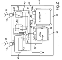
- the structure of the mobile radio unit 18 is described below with reference to FIG Fig. 2 explained again in more detail.
- the mobile radio module 36 and the mobile radio module 38 may each be, for example, an application specific integrated circuit (ASIC), a field programmable gate array (FPGA), a DSP (digital signal processor) or a general purpose processing unit (CPU).
- ASIC application specific integrated circuit
- FPGA field programmable gate array
- DSP digital signal processor
- CPU general purpose processing unit
- Mobile radio modules such as the mobile radio module 36 and the mobile radio module 38 are known per se from the prior art.
- the mobile radio unit 18 further comprises a switching device 40 and a splitter 42.
- the main antenna 22 is connected to the mobile radio unit 18 via a main antenna connection 44.
- the secondary antenna 26 is connected to the mobile radio unit 18 via a secondary antenna port 46.
- the mobile radio module 38 is connected to the switching device 40 via a signal connection 48 for transmitting and receiving a mobile radio signal.
- the switching device 40 may be, for example, an integrated circuit.
- a signal connection 50 of the mobile radio module 36 is likewise connected to a connection S2 of the switching device 40.
- the main antenna connection 44 is connected to a connection S3 of the switching device 40, a connection A3 of the splitter 42 to a connection S4 of the switching device 40.
- a connection A2 of the splitter 42 is connected to a further signal connection 50 of the mobile radio module 38. Between the terminal A2 and the terminal A3 of the splitter 42, the splitter 42 may have an attenuation of, for example, 20 dB.
- a terminal A1 of the splitter 20 is connected to the secondary antenna terminal 46.
- a control line 52 connects a control output 54 of the mobile radio module 36 to a control input 56 of the switching device 40.
- the mobile radio module 36 can thereby switch two switches 58, 60 of the switching device 40.
- the terminal S1 is connected via the switch 60 to the terminal S3 and the terminal S2 via the switch 58 to the terminal S4.
- the signal connection 48 of the mobile radio module 38 is coupled via the switching device 40 to the main antenna 22 and the signal connection 46 to the secondary antenna 26.
- the switching device 40 is shown in a second switching state, in which the terminal S2 is connected via the switch 60 to the terminal S3 and the terminal S1 via the switch 58 to the terminal S4.
- the mobile radio module 38 is connected via its signal connection 48 with the secondary antenna 26 and the mobile radio module 36 via its signal connection 46 with the main antenna 22.
- the splitter 42 of the other signal terminal 50 of the mobile module 38 is permanently connected to the secondary antenna 26.
- the mobile radio module 38 is designed to enable reception via the two signal connections 48, 50 on the basis of an antenna diversity formed by means of the antennas 22, 26.
- the switching device 40 must be switched in the first switching state.
- a signal 62 for displaying a transmission pulse of the second module can be generated by the second mobile radio module.
- Protective measures for the signal connection 50 of the first mobile radio module can be taken with this signal.
- Fig. 2 This is, for example, the brief interruption of the antenna signal to the signal terminal 50th
- the GSM module controls the switching logic of the antennas, ie the switching device 14. This ensures that during a telephone call the GSM mobile radio module can reach the surrounding base stations, ie the base station 30 by radio, with as little shielding as possible.
- the mobile radio unit 18 is preferably realized as a plug-in card, which may be inserted, for example, in a dedicated Einsteckblatt the infotainment system 14. It can be provided that the control of the GSM mobile radio module 36 by the mobile radio module 38 takes place. This results in the advantage that the other components of the infotainment system 14 must be designed exclusively to communicate with the mobile radio module 38, ie to exchange the data to be transmitted or the received data. A division of the data between the mobile radio module 38 and the mobile radio module 36 can then take place within the mobile radio unit 18 by a corresponding signal processing of the mobile radio module 38.
- the switching over of the switching device 40 can also take place while the mobile radio module 38 is already exchanging user data with the mobile radio station 32.
- Mobile radio standards are usually designed such that a change in the transmission characteristic of the radio link does not lead to a complete disconnection. If, therefore, the switching device 40 is switched from the first switching state (antenna diversity) to the second switching state (signal connections 48 and 50 are both coupled to the secondary antenna 26), an adaptation of the transmission behavior of the mobile radio module 38 takes place in the usual way and the user data transmission can also take place a reduced transmission rate.
- the reduced data transmission rate is usually not noticeable to the user, since the switching to the second switching state only takes place when a telephone call arrives or a telephone connection is established from the telephone 12. In other words, the switching takes place only when the user of the motor vehicle 10 is on the phone, which is not noticeable during a telephone conversation.
Description
Die Erfindung betrifft eine Mobilfunkvorrichtung für einen Kraftwagen, die zwei Mobilfunkmodule aufweist, mittels welchen ein Mobilfunksignal mit einer externen Mobilfunkstation ausgetauscht werden kann. Die Erfindung betrifft auch einen Kraftwagen mit einer solchen Mobilfunkvorrichtung sowie ein Verfahren zum Betreiben der Mobilfunkvorrichtung. Mit einem Kraftwagen wird vorliegend insbesondere ein Personenkraftwagen und ein Lastkraftwagen verstanden.The invention relates to a mobile radio device for a motor vehicle, which has two mobile radio modules, by means of which a mobile radio signal can be exchanged with an external mobile radio station. The invention also relates to a motor vehicle with such a mobile radio device and to a method for operating the mobile radio device. In the present case, a motor vehicle is understood to mean in particular a passenger car and a truck.
Bei einem solchen Kraftwagen kann durch Mobilfunkmodul ermöglicht sein, von einem Telefon des Kraftwagens aus Telefonate über das Mobilfunknetzwerk eines Mobilfunkbetreibers zu führen. Ein solches Mobilfunkmodul umfasst in der Regel einen oder mehrere integrierte Schaltkreise (Computerchip), die aus den zu versendenden digitalen Daten ein Mobilfunksignal erzeugen, das über einen Signalanschluss an eine Antenne ausgegeben werden kann, um von dort zu einer Mobilfunkstation gesendet zu werden. Umgekehrt kann ein von einer solchen Mobilfunkstation empfangenes Mobilfunksignal durch das Mobilfunkmodul verarbeitet werden, um so die im Mobilfunksignal enthaltenen Sprachdaten zu extrahieren. Neben der Telefonie ist über eine solche Mobilfunkanbindung auch die Übertragung von digitalen Nutzdaten anderer Art möglich, insbesondere Netzwerkdaten für einen Datenaustausch mit dem Internet, also beispielsweise E-Mails oder Browserdaten.In such a car can be made possible by mobile phone module to lead from a phone of the car from phone calls over the mobile network of a mobile operator. Such a mobile radio module generally comprises one or more integrated circuits (computer chip) which generate from the digital data to be transmitted a mobile radio signal which can be output via a signal connection to an antenna in order to be transmitted from there to a mobile radio station. Conversely, a mobile radio signal received by such a mobile radio station can be processed by the mobile radio module so as to extract the voice data contained in the mobile radio signal. In addition to the telephony, the transmission of digital user data of another type is possible via such a mobile radio connection, in particular network data for a data exchange with the Internet, so for example e-mails or browser data.
Mit der fortschreitenden Entwicklung der Mobilfunktechnologie muss in einem Kraftwagen sichergestellt sein, dass die darin verbaute Mobilfunkvorrichtung auch mit den Mobilfunkstationen unterschiedlicher Mobilfunkstandards kommunizieren kann. Hierzu ist beispielsweise bekannt, in einer Mobilfunkvorrichtung ein Mobilfunkmodul bereitzustellen, für eine Übertragung gemäß dem GSM-Standard (global system for mobile communications) oder für Signalübertragung gemäß dem UMTS-Standard (UMTS - universal mobile telecommunication system) ausgelegt ist. Eine Datenübertragung zwischen den Kraftwagen und einem Mobilfunknetzwerk findet dann jeweils über dasjenige Mobilfunkmodul statt, zu welchem eine passende Mobilfunkstation in der Umgebung des Kraftwagens verfügbar ist.With the progressive development of mobile radio technology, it must be ensured in a motor vehicle that the mobile radio device incorporated therein can also communicate with the mobile radio stations of different mobile radio standards. For this purpose, it is known, for example, to provide a mobile radio module in a mobile radio device, for transmission according to the GSM standard (global system for mobile communications) or is designed for signal transmission according to the UMTS standard (UMTS - universal mobile telecommunication system). A data transmission between the motor vehicle and a mobile radio network then takes place in each case via that mobile radio module to which a suitable mobile radio station in the vicinity of the motor vehicle is available.
Im Zusammenhang mit einem Mehrwegeempfang von Mobilfunksignalen ist bekannt, in einem Kraftwagen zwei oder mehr Antennen bereitzustellen.In connection with a multipath reception of mobile radio signals, it is known to provide two or more antennas in a motor vehicle.
Bei der Entwicklung eines Kraftwagens muss im Zusammenhang mit der Bereitstellung von Mobilfunkvorrichtungen für neue Telekommunikationsstandards beachtet werden, dass solche neuen Standards in den ersten Jahren nach der Einführung nicht immer zuverlässig funktionieren. Beispielsweise wird bei dem neuen LTE-Standard (LTE - long term evolution) die vorgesehene Übertragungsart für Telefonie VoLTE noch nicht von den Mobilfunknetzen unterstützt. Statt dessen muss auf einen älteren Standard beispielsweise UMTS oder GSM zurückgeschaltet werden. Die Implementierung von LTE im Fahrzeug wird deshalb erfahrungsgemäß mit technischen Schwierigkeiten verbunden sein, so dass es wünschenswert ist, eine redundante Fallback-Lösung zu haben. Aus dem Dokument
Die Erfindung weist den Vorteil auf, dass mit einem Antennensystem aus zwei oder mehr Antennen für Antennendiversität zwei unterschiedliche Mobilfunkmodule zugleich betrieben werden können, ohne dass es hierbei zu einem für den Benutzer der Mobilfunkvorrichtung in einem Kraftwagen relevanten Bandreduktion der Übertragungsbandbreite kommt. Bei der für die Antennendiversität bereitgestellten ersten und zweiten Antenne ist in der Regel davon auszugehen, dass eine davon, im Folgenden sei davon ausgegangen, dass es sich um die erste Antenne handelt, eine für einen störungsfreien Signalaustausch günstigere Position im Kraftwagen aufweist, während die zweite Antenne als Hilfsantenne für die Antennendiversität darstellt. Für den Fall, dass nur das erste Mobilfunkmodul ein Mobilfunksignal überträgt und hierbei beide Antennen für die Antennendiversitäten nutzt, kann mittels der Schalteinrichtung das zweite Mobilfunkmodul auf die zweite Antenne, d.h. die Hilfsantenne, geschaltet sein, so dass über die zweite Antenne von dem zweiten Mobilfunkmodul immer noch Kontrolldaten von einer Mobilfunkstation empfangen werden können. Sobald auch das zweite Mobilfunkmodul für die Übertragung eines Mobilfunksignals genutzt werden soll, kann mittels der Schalteinrichtung das zweite Mobilfunkmodul auf die erste Antenne, also die Hauptantenne mit den besseren Sendeeigenschaften, geschaltet werden. Für diesen Zeitraum kann das erste Mobilfunkmodul mit der zweiten Antenne verbunden werden und weiter die Signalübertragung mittels der zweiten Antenne durchführen.The invention has the advantage that with an antenna system comprising two or more antennas for antenna diversity, two different mobile radio modules can be operated at the same time, without resulting in a band reduction of the transmission bandwidth relevant for the user of the mobile radio device in a motor vehicle. In the case of the first and second antenna provided for the antenna diversity, it is generally to be assumed that one of them, which is assumed to be the first antenna in the following, has a more favorable position in the motor vehicle for interference-free signal exchange, while the second one Antenna represents an auxiliary antenna for the antenna diversity. In the event that only the first mobile radio module transmits a mobile radio signal and in this case uses both antennas for the antenna diversity, the second mobile radio module can be switched to the second antenna, ie the auxiliary antenna, by means of the switching device, so that via the second antenna from the second mobile radio module Control data can still be received from a mobile station. As soon as the second mobile radio module is to be used for the transmission of a mobile radio signal, the second mobile radio module can be switched to the first antenna, ie the main antenna with the better transmission characteristics, by means of the switching device. For this period, the first mobile module with the second antenna be connected and continue to carry out the signal transmission by means of the second antenna.
Der erfindungsgemäße Kraftwagen zeichnet sich dadurch aus, dass er eine Ausführungsform der erfindungsgemäßen Mobilfunkvorrichtung aufweist. Bei dem erfindungsgemäßen Kraftwagen ist es insbesondere nicht nötig, dass die beiden Antennen in gleichem Maße für eine störungsfreie Übertragung eines Mobilfunksignals geeignet sein müssen. Entsprechend sieht eine Ausführungsform des erfindungsgemäßen Kraftwagens vor, dass die erste Antenne einen kleineren Richtfaktor aufweist als die zweite Antenne. Der kleinere Richtfaktor besagt, dass die erste Antenne durch die übrigen Bauteile des Kraftwagens weniger stark zur Umgebung hin abgeschirmt ist, als die zweite Antenne. Mittels der ersten Antenne ist es also einfacher, ein Mobilfunksignal mit einer Mobilfunkstation in einer beliebigen Richtung in der Umgebung des Kraftwagens auszutauschen. Die Ausführungsform weist den Vorteil auf, dass die zweite Antenne an einem weniger exponierten Ort des Kraftwagens, beispielsweise in einer Stoßstange, angeordnet sein kann. In Bezug auf die erste Antenne ist diese bevorzugt auf einem Dach des Kraftwagens angeordnet. Hierdurch ist es möglich, mittels der ersten Antenne in einer horizontalen Ebene rund um den Kraftwagen eine Sichtverbindung mit Mobilfunkstationen zu erhalten.The motor vehicle according to the invention is characterized in that it has an embodiment of the mobile device according to the invention. In the motor vehicle according to the invention, it is in particular not necessary that the two antennas must be equally suitable for trouble-free transmission of a mobile radio signal. Accordingly, an embodiment of the motor vehicle according to the invention provides that the first antenna has a smaller directivity factor than the second antenna. The smaller directivity factor means that the first antenna is less shielded from the environment by the other components of the motor vehicle than the second antenna. By means of the first antenna, it is thus easier to exchange a mobile radio signal with a mobile radio station in any direction in the vicinity of the motor vehicle. The embodiment has the advantage that the second antenna can be arranged at a less exposed location of the motor vehicle, for example in a bumper. With respect to the first antenna, this is preferably arranged on a roof of the motor vehicle. This makes it possible to obtain a visual connection with mobile stations by means of the first antenna in a horizontal plane around the motor vehicle.
Es wird insbesondere vorgesehen, mittels des ersten Mobilfunkmoduls eine Signalübertragung gemäß einem moderneren Mobilfunkstandard zu ermöglichen als mit dem zweiten Mobilfunkmodul. Entsprechend einer Weiterbildung der erfindungsgemäßen Mobilfunkvorrichtung ist daher das erste Mobilfunkmodul dazu ausgelegt, von Sprachdaten verschiedene digitale Nutzerdaten mittels des ersten Mobilfunksignals auszutauschen, also die Daten betreffend eine Videoübertragung, E-Mails, Internetdaten betreffend Internetseiten und dergleichen. Das zweite Mobilfunkmodul ist dagegen bevorzugt dazu ausgelegt, als das zweite Mobilfunksignal ein Sprachtelefoniesignal auszutauschen. Hierdurch ergibt sich der Vorteil, mittels des ersten Mobilfunkmoduls eine modernere breitbandige Anbindung von Datenverarbeitungsgeräten an ein Datennetzwerk, insbesondere das Internet, bereitzustellen. Rechtzeitig kann mittels des zweiten Mobilfunkmoduls eine robuste, ältere Technologie für die störungsfreie Sprachübertragung bereitgestellt sein. Insbesondere ist bei dem erfindungsgemäßen Mobilfunkmodul vorgesehen, dass das erste Mobilfunkmodul das Mobilfunksignal gemäß zumindest einem aus den folgenden Mobilfunkstandards austauscht: LTE, UMTS, HSPA (high speed packet access). Entsprechend ist gemäß einer Weiterbildung der Mobilfunkvorrichtung vorgesehen, dass das zweite Mobilfunkmodul ein GSM-Modul ist.In particular, it is provided to enable a signal transmission according to a more modern mobile radio standard by means of the first mobile radio module than with the second mobile radio module. According to a further development of the mobile radio device according to the invention, therefore, the first mobile radio module is adapted to exchange different digital user data from voice data by means of the first mobile radio signal, that is to say the data relating to a video transmission, e-mails, Internet data relating to Internet pages and the like. By contrast, the second mobile radio module is preferably designed to exchange a voice telephony signal as the second mobile radio signal. This has the advantage of providing a more modern broadband connection of data processing devices to a data network, in particular the Internet, by means of the first mobile radio module. In good time, a robust, older technology for interference-free voice transmission can be provided by means of the second mobile radio module. In particular, it is provided in the mobile radio module according to the invention that the first mobile radio module exchanges the mobile radio signal according to at least one of the following mobile radio standards: LTE, UMTS, HSPA (high speed packet access). Accordingly, according to a further development of the mobile radio device it is provided that the second mobile radio module is a GSM module.
Um für die beiden Mobilfunkmodule je nach Situation möglichst günstige Sende- und/oder Empfangsbedingungen zu schaffen, sieht das erfindungsgemäße Verfahren vor, während einer Übertragung eines Sprachtelefoniesignals die Umschalteinrichtung im zweiten Schaltzustand zu halten und ansonsten die Umschalteinrichtung im ersten Schaltzustand zu halten. Mit anderen Worten ist während der Übertragung eines Sprachtelefoniesignals das zweite Mobilfunkmodul mit der ersten Antenne gekoppelt, von der hier ausgegangen wird, dass es sich um die Antenne mit den günstigeren Sende- und/oder Empfangseigenschaften handelt. Das erste Mobilfunkmodul ist während dessen mit der zweiten, schwächeren Antenne gekoppelt. Sobald das Telefonat beendet ist, also keine Sprachtelefoniesignale mehr übertragen werden, wird die Umschalteinrichtung wieder in den ersten Schaltzustand gebracht, so dass das erste Mobilfunkmodul wieder über die erste Antenne sendet bzw. empfängt. Das erfindungsgemäße Verfahren weist den Vorteil auf, dass einem Nutzer während eines Telefonats stets die beste mögliche Signalverbindung während eines Telefonats mittels des zweiten Mobilfunkmoduls bereitgestellt wird. Nutzt der Benutzer dagegen das erste Mobilfunkmodul, um beispielsweise im Internet Informationen zu suchen, wird während dessen ebenfalls in der Regel die erste Antenne genutzt. In diesem Zusammenhang hat sich herausgestellt, dass eine Verzögerung der Datenübertragung für den Fall, dass der Benutzer während des Herunterladens von Informationen aus dem Internet telefoniert, vom Benutzer kaum wahrgenommen wird. Daher ist es unproblematisch, wenn während eines Telefonats das erste Mobilfunkmodul lediglich über die zweite Antenne Mobilfunksignale austauschen kann.In order to create the best possible transmission and / or reception conditions for the two mobile radio modules depending on the situation, the method according to the invention provides to keep the switching device in the second switching state during a transmission of a voice telephony signal and otherwise to keep the switching device in the first switching state. In other words, during the transmission of a voice telephony signal, the second mobile radio module is coupled to the first antenna, which is assumed to be the antenna with the more favorable transmission and / or reception characteristics. The first mobile radio module is thereby coupled to the second, weaker antenna. As soon as the call has ended, ie no voice telephony signals are transmitted, the switching device is brought back into the first switching state, so that the first mobile radio module transmits or receives again via the first antenna. The method according to the invention has the advantage that a user is always provided with the best possible signal connection during a telephone call by means of the second mobile radio module during a telephone call. If, on the other hand, the user uses the first mobile radio module in order, for example, to search for information on the Internet, the first antenna is usually used during this as well. In this connection, it has been found that a delay in data transmission in the event that the user makes a telephone call during the downloading of information from the Internet is barely noticed by the user. Therefore, it is not a problem if, during a telephone call, the first mobile radio module can only exchange mobile radio signals via the second antenna.
In Bezug auf die Steuerung der Schalteinrichtung sieht eine Weiterbildung der erfindungsgemäßen Mobilfunkvorrichtung eine Umschalteinrichtung vor, die dazu ausgelegt ist, durch Erzeugen eines vorbestimmten Schaltsignals die Schalteinrichtung zu Beginn einer Sprachübertragung in den zweiten Schaltzustand zu schalten. Hierdurch ergibt sich der Vorteil, dass das zweite Mobilfunkmodul nur bei Bedarf die erste Antenne nutzt und ansonsten Kontrolldaten und dergleichen über die zweite Antenne mit Mobilfunkstationen austaucht. Zweckmäßigerweise ist die Umschalteinrichtung als Bestandteil des zweiten Mobilfunkmoduls bereitgestellt. In diesem Fall ist ein Steuerausgang des zweiten Mobilfunkmoduls zum Ausgeben des beschriebenen Steuersignals mit einem Steuereingang der Schalteinrichtung gekoppelt. Hierdurch ergibt sich der Vorteil, dass das zweite Mobilfunkmodul immer dann selbständig die Schalteinrichtung von dem ersten in den zweiten Schaltzustand umschalten kann, wenn im zweiten Mobilfunkmodul der Bedarf für eine Signalübertragung über die erste Antenne erkannt wird.With regard to the control of the switching device, a development of the mobile radio device according to the invention provides a switching device which is designed to switch the switching device by generating a predetermined switching signal at the beginning of a voice transmission in the second switching state. This results in the advantage that the second mobile radio module uses the first antenna only when needed and otherwise dips control data and the like via the second antenna with mobile radio stations. Conveniently, the switching device is provided as part of the second mobile radio module. In this case, a control output of the second mobile radio module for outputting the described control signal coupled to a control input of the switching device. This results in the advantage that the second mobile radio module can automatically switch the switching device from the first to the second switching state whenever the need for a signal transmission via the first antenna is detected in the second mobile radio module.
In diesem Zusammenhang sieht eine Weiterbildung des erfindungsgemäßen Verfahrens vor, dass bei einem Anruf von außerhalb des Kraftwagens die Schalteinrichtung vom ersten in den zweiten Schaltzustand durch Erzeugen eines vorbestimmten Schaltsignals umgeschaltet wird. Hierdurch ergibt sich der Vorteil, dass eintreffende Telefonanrufe über die erste Antenne empfangen werden.In this connection, a development of the method according to the invention provides that, in the case of a call from outside the motor vehicle, the switching device is switched over from the first to the second switching state by generating a predetermined switching signal. This has the advantage that incoming telephone calls are received via the first antenna.
Eine andere Weiterbildung des erfindungsgemäßen Verfahrens sieht vor, dass bei einem Rufaufbau eine Sprachverbindung durch das zweite Mobilfunkmodul die Schalteinrichtung ebenfalls vom ersten in den zweiten Schaltzustand durch Erzeugen eines vorbestimmten Schaltsignals umgeschaltet wird. Hierdurch ergibt sich der Vorteil, dass auch vom Fahrzeug ausgehende Sprachverbindungen über die erste Antenne versendet werden.Another development of the method according to the invention provides that in a call setup a voice connection by the second mobile radio module, the switching device is also switched from the first to the second switching state by generating a predetermined switching signal. This has the advantage that voice connections originating from the vehicle are also transmitted via the first antenna.
Um die beiden Antennen im Rahmen einer Antennendiversität für das erste Mobilfunkmodul nutzbar zu machen, sieht eine Weiterbildung der Mobilvorrichtung vor, dass das erste Mobilfunkmodul einen weiteren Signalanschluss aufweist, der permanent mit der zweiten Antenne verbunden ist, also durchgehend und unabhängig vom Schaltzustand der Schalteinrichtung.In order to make the two antennas usable in the context of antenna diversity for the first mobile radio module, a development of the mobile device provides that the first mobile radio module has a further signal connection which is permanently connected to the second antenna, that is, continuously and independently of the switching state of the switching device.
Zweckmäßigerweise ist hierbei die zweite Antenne über einen Splitter mit der Schalteinrichtung einerseits und dem weiteren Signalanschluss andererseits verbunden. Hierdurch ergibt sich der Vorteil, dass bei der gleichzeitigen Nutzung beider Antennen durch das erste Mobilfunkmodul sich nur ein verhältnismäßig geringer Leistungsverlust des ersten Mobilfunksignals ergibt. Mit anderen Worten lässt sich mittels des ersten Mobilfunkmoduls und der Antennendiversität nahezu dieselbe Übertragungsqualität bei der erfindungsgemäßen Mobilfunkvorrichtung bereitstellen, wie bei einer herkömmlichen Mobilfunkvorrichtung, die nur ein einzelnes Mobilfunkmodul und zugeordnete Antennen aufweist.Appropriately, in this case the second antenna is connected via a splitter with the switching device on the one hand and the other signal terminal on the other. This results in the advantage that with the simultaneous use of both antennas by the first mobile radio module, only a relatively low power loss of the first mobile radio signal results. In other words, by means of the first mobile radio module and the antenna diversity nearly the same transmission quality can be provided in the mobile radio device according to the invention, as in a conventional mobile radio device having only a single mobile radio module and associated antennas.
Das erfindgsgemäße Verfahren sieht des weiteren vor, dass die Dämpfung des Antennensignals für das zweite Mobilfunkmodul durch schaltungstechnische Maßnahmen minimiert ist. Im Falle einer Sprachverbindung wird die erste Antenne mit nur einem Umschalter auf das zweite Mobilfunkmodul geschaltet.The inventive method further provides that the attenuation of the antenna signal for the second mobile radio module by circuitry Measures is minimized. In the case of a voice connection, the first antenna is switched to the second mobile radio module with only one switch.
Im Falle eines Betriebs im GSM Funknetz kann ein Sendeimpuls des zweiten Empfangsmoduls die Empfangseigenschaften des ersten Mobilfunkmoduls verschlechtern. Das erfindungsgemäße Verfahren sieht des weiteren vor, dass vom zweiten Mobilfunkmodul ein Signal vor einem Sendeimpuls generiert wird. Dieses Signal kann dazu verwendet werden, im Falle eines Sendeimpulses des zweiten Moduls für das erste Modul Schutzmechanismen zu ergreifen. Beispielsweise kann im Falle eines Sendeimpulses das Antennensignal kurzzeitig vom ersten Modul getrennt werden.In the case of operation in the GSM radio network, a transmission pulse of the second reception module may impair the reception characteristics of the first mobile radio module. The method according to the invention further provides that the second mobile radio module generates a signal before a transmission pulse. This signal can be used to take protective measures in the event of a transmission pulse of the second module for the first module. For example, in the case of a transmission pulse, the antenna signal can be disconnected from the first module for a short time.
In Bezug auf die schaltungstechnische Realisierung der erfindungsgemäßen Mobilfunkvorrichtung umfasst diese bevorzugt eine Einsteckkarte, auf welcher beide Mobilfunkmodule angeordnet sind. Hierdurch ergibt sich der Vorteil, dass das erfindungsgemäße Mobilfunkmodul in einen Steckplatz eingesteckt werden kann, der für eine herkömmliche Mobilfunkvorrichtung mit nur einem Mobilfunkmodul vorgesehen ist. Hierdurch ist es nicht nötig, bei einer Neuentwicklung eines Kraftwagens auch weitere schaltungstechnische Maßnahmen für die Nutzung beider Mobilfunkmodule des erfindungsgemäßen Mobilfunkmoduls vorzusehen. Sämtliche schaltungstechnisch benötigten Elemente können auf der einen Einsteckkarte bereitgestellt sein.With regard to the circuitry realization of the mobile radio device according to the invention, this preferably comprises a plug-in card, on which both mobile radio modules are arranged. This results in the advantage that the mobile radio module according to the invention can be plugged into a slot which is provided for a conventional mobile radio device with only one mobile radio module. As a result, it is not necessary to provide further circuitry measures for the use of both mobile radio modules of the mobile radio module according to the invention in a new development of a motor vehicle. All elements required for circuit technology can be provided on the one plug-in card.
Im Folgenden wird die Erfindung noch einmal genau anhand eines konkreten Ausführungsbeispiels erläutert. Dazu zeigt:
- Fig. 1
- eine schematische Darstellung einer bevorzugten Ausführungsform des erfindungsgemäßen Kraftwagens und
- Fig. 2
- einen schematischen Aufbau einer Ausführungsform der erfindungsgemäßen Mobilfunkvorrichtung wie sie in dem Kraftwagen von
Fig. 1 eingebaut sein kann.
- Fig. 1
- a schematic representation of a preferred embodiment of the motor vehicle according to the invention and
- Fig. 2
- a schematic structure of an embodiment of the mobile device according to the invention as in the motor vehicle of
Fig. 1 can be installed.
Bei dem im Folgenden erläuterten Beispiel stellen die beschriebenen Komponenten des Kraftwagens und der Mobilfunkvorrichtung jeweils einzelne, unabhängig voneinander zu betrachtende Merkmale der Erfindung dar, welche die Erfindung jeweils auch unabhängig voneinander weiterbilden und damit auch einzeln oder in einer anderen als der gezeigten Kombination als Bestandteil der Erfindung anzusehen sind. Des Weiteren ist die beschriebene Ausführungsform auch durch weitere der bereits beschriebenen Merkmale der Erfindung ergänzbar.In the example explained below, the described components of the motor vehicle and the mobile device each represent individual, independently of each other to be considered features of the invention, which each further independently form the invention and thus individually or in a different than the combination shown as To be considered part of the invention. Furthermore, the described embodiment can also be supplemented by further features of the invention already described.
In
Die Mobilfunkeinheit 18 ist in der Lage, mit beiden Mobilfunkstationen 30, 32 gemäß dem jeweiligen Mobilfunkstandards (hier in diesem Beispiels also GSM und LTE) Daten auszutauschen. Die Mobileinheit 18 weist hierzu ein GSM-Mobilfunkmodul 36 und ein LTE-Mobilfunkmodul oder kombiniertes LTE/UMTS/GSM-Mobilfunkmodul 38 auf. Der Aufbau der Mobilfunkeinheit 18 ist im Folgenden anhand von
Bei dem Mobilfunkmodul 36 und dem Mobilfunkmodul 38 kann es sich jeweils beispielsweise um einen ASIC (application specific integrated circuit), ein FPGA (field programmable gate array), ein DSP (digitaler Signalprozessor) oder eine CPU (general purpose processing unit) handeln. Mobilfunkmodule wie das Mobilfunkmodul 36 und das Mobilfunkmodul 38 sind an sich aus dem Stand der Technik bekannt. Die Mobilfunkeinheit 18 umfasst des Weiteren eine Schalteinrichtung 40 und einen Splitter 42. Die Hauptantenne 22 ist über einen Hauptantennenanschluss 44 an die Mobilfunkeinheit 18 angeschlossen. Die sekundäre Antenne 26 ist über einen sekundären Antennenanschluss 46 an die Mobilfunkeinheit 18 angeschlossen.The
Das Mobilfunkmodul 38 ist über einen Signalanschluss 48 zum Senden und Empfangen eines Mobilfunksignals mit der Schalteinrichtung 40 verbunden. Bei der Schalteinrichtung 40 kann es sich beispielsweise um eine integrierte Schaltung handeln. Ein Signalanschluss 50 des Mobilfunkmoduls 36 ist ebenfalls mit einem Anschluss S2 der Schalteinrichtung 40 verbunden. Der Hauptantennenanschluss 44 ist mit einem Anschluss S3 der Schalteinrichtung 40 verbunden, ein Anschluss A3 des Splitters 42 mit einem Anschluss S4 der Schalteinrichtung 40. Ein Anschluss A2 des Splitters 42 ist mit einem weiteren Signalanschluss 50 des Mobilfunkmoduls 38 verbunden. Zwischen dem Anschluss A2 und dem Anschluss A3 des Splitters 42 kann der Splitter 42 eine Dämpfung von z.B. 20 dB aufweisen. Ein Anschluss A1 des Splitters 20 ist mit dem sekundären Antennenanschluss 46 verbunden. Eine Steuerleitung 52 verbindet einen Steuerausgang 54 des Mobilfunkmoduls 36 mit einem Steuereingang 56 der Schalteinrichtung 40. Durch Erzeugen eines Schaltsignals am Schaltausgang 54 kann das Mobilfunkmodul 36 hierdurch zwei Schalter 58, 60 der Schalteinrichtung 40 umschalten. In einem ersten Schaltzustand ist der Anschluss S1 über den Schalter 60 mit dem Anschluss S3 verbunden und der Anschluss S2 über den Schalter 58 mit dem Anschluss S4. Entsprechend ist im ersten Schaltzustand der Signalanschluss 48 des Mobilfunkmoduls 38 über die Schalteinrichtung 40 mit der Hauptantenne 22 und der Signalanschluss 46 mit der sekundären Antenne 26 gekoppelt. In
Des weiteren kann vom zweiten Mobilfunkmodul ein Signal 62 zum Anzeigen eines Sendeimpuls des zweiten Moduls generiert werden. Mit diesem Signal können Schutzmaßnahmen für den Signalanschluss 50 des ersten Mobilfunkmoduls ergriffen werden. In
Bei dem Kraftwagen 10 werden Telefongespräche mittels des Telefons 12 über das Mobilfunkmodul 36, d.h. das GSM-Mobilfunkmodul übertragen. Die übrigen Nutzdaten werden über das LTE-Mobilfunkmodul 38 übertragen. Durch den Aufbau der Mobilfunkeinheit 18 teilen sich beide Mobilfunkmodule 36, 38 die Antennen 22, 26. Wie bereits ausgeführt, weist die Hauptantenne 22 bessere Empfangseigenschaften als die Antenne 26 auf. Bei der Mobilfunkeinheit 18 wird bedarfsweise die Antenne mit den besseren Empfangseigenschaften, d.h. die Hauptantenne 22, dem LTE- oder dem GSM-Mobilfunkmodul zugeschaltet. Beispielsweise kann vorgesehen sein, während eines Telefonats die Hauptantenne 22 mit dem GSM-Modul, d.h. dem Mobilfunkmodul 36, zu verbinden. Hierzu wird die Schalteinrichtung 40 in den zweiten Schaltzustand geschaltet. In dem in
Das Umschalten der Schalteinrichtung 40 kann auch erfolgen, während das Mobilfunkmodul 38 bereits Nutzerdaten mit der Mobilfunkstation 32 austauscht. Mobilfunkstandards sind in der Regel derart ausgelegt, dass eine Veränderung der Übertragungscharakteristik der Funkstrecke nicht zu einem vollständigen Verbindungsabbruch führt. Wird also die Schalteinrichtung 40 vom ersten Schaltzustand (Antennendiversität) in den zweiten Schaltzustand geschaltet (Signalanschlüsse 48 und 50 sind beide mit der sekundären Antenne 26 gekoppelt), so erfolgt in der gewohnten Weise eine Anpassung des Übertragungsverhaltens des Mobilfunkmoduls 38 und es kann die Nutzdatenübertragung mit einer verringerten Übertragungsrate fortgesetzt werden. Die verringerte Datenübertragungsrate fällt dem Benutzer in der Regel nicht auf, da das Umschalten in den zweiten Schaltzustand nur erfolgt, wenn ein Telefongespräch eintrifft oder eine Telefonverbindung vom Telefon 12 aus aufgebaut wird. Mit anderen Worten findet das Umschalten nur statt, wenn der Benutzer des Kraftwagens 10 telefoniert, was während eines Telefongesprächs nicht auffällt.The switching over of the
Claims (15)
- Mobile communications device for a motor vehicle (10), comprising:- a first mobile communications module (38) for exchanging a first mobile communications signal in accordance with a first mobile communications standard or several mobile communications standards via a first signal connection (48) of the first mobile communications module (38) with an external mobile communications station (32),- a second mobile communications module (36) for exchanging a second mobile communications signal in accordance with a second mobile communications standard via a second signal connection (46) of the second mobile communications module (36) with an external mobile communications station (30),- a first antenna (22) and a second antenna (26) for transmitting the mobile communications signals,- a switching device (40) which is connected to the antennae (22, 26) and to the first and second signal connection (46, 48) and is designed to switch over, in dependence on a switching signal, between a first switching state in which the first signal connection (48) is connected to the first antenna (22) and the second signal connection (46) to the second antenna (26), and a second switching state in which the first signal connection (48) is connected to the second antenna (26) and the second signal connection (46) to the first antenna (22),characterised in that
the first mobile communications module (38) has a further signal connection (50), which irrespective of the switching state of the switching device (40) is continuously connected to the second antenna (26). - Mobile communications device according to claim 1, characterised in that the first mobile communications module (38) is designed to exchange digital user data different from voice data by means of the first mobile communications signal, and the second mobile communications module (36) is designed to exchange a voice telephony signal as the second mobile communications signal.
- Mobile communications device according to claim 1 or 2, characterised by a switch-over device (54) which is designed, through generating a predetermined switching signal, to switch the switching device (40) into the second switching state at the start of voice transmission.
- Mobile communications device according to claim 3, characterised in that the switch-over device is provided in the second mobile communications module (36) and a control output (54) of the second mobile communications module (36) is connected with a control input (56) of the switching device (40) to send out the control signal.
- Mobile communications device according to any one of the preceding claims, characterised in that the second mobile communications module (36) is a GSM module.
- Mobile communications device according to any one of the preceding claims, characterised in that the first mobile communications module (38) is designed to exchange the first mobile communications signal in accordance with at least one of the following mobile communications standards: LTE, HSPA, UMTS.
- Mobile communications device according to any one of the preceding claims, characterised in that the second antenna (26) is connected by means of a splitter (42) to the switching device (40) on the one hand and to the further signal connection (50) on the other hand.
- Mobile communications device according to any one of the preceding claims, characterised in that the first and the second mobile communications module (36, 38) are arranged on a common insert card.
- Mobile communications device according to any one of the preceding claims, characterised by a switch-over device (54) which is designed to minimise the antenna losses for the second mobile communications module through the use of only a single switch in the case of a telephone conversation.
- Mobile communications device according to any one of the preceding claims, which in the event of a GSM send impulse by the second module is designed to take protective measures for the first mobile communications module.
- Motor vehicle (10) with a mobile communications device according to any one of the preceding claims.
- Motor vehicle (10) according to claim 11, characterised in that the first antenna (22) has a smaller directivity factor than the second antenna.
- Method for operating a mobile communications device according to any one of claims 1 to 10 with which during a transmission of a telephony signal the switching device (40) is held in the second switching state and otherwise the switching device (40) is held in the first switching state.
- Method according to claim 13, characterised in that in the case of a call from outside the motor vehicle (10) the switching device (40) is switched from the first into the second switching state through the generation of a predetermined switching signal.
- Method according to claim 13 or 14, characterised in that in the case of a call setup for a voice connection through the second mobile communications module (36) the switching device (40) is switched over from the first into the second switching state through the generation of a predetermined switching signal.
Applications Claiming Priority (2)
| Application Number | Priority Date | Filing Date | Title |
|---|---|---|---|
| DE102012014548.9A DE102012014548B3 (en) | 2012-07-21 | 2012-07-21 | Mobile device for a motor vehicle, and method for operating the mobile device |
| EP13736481.6A EP2875584B1 (en) | 2012-07-21 | 2013-06-26 | Mobile wireless device for a motor vehicle, and method for operating the mobile wireless device |
Related Parent Applications (2)
| Application Number | Title | Priority Date | Filing Date |
|---|---|---|---|
| EP13736481.6A Division-Into EP2875584B1 (en) | 2012-07-21 | 2013-06-26 | Mobile wireless device for a motor vehicle, and method for operating the mobile wireless device |
| EP13736481.6A Division EP2875584B1 (en) | 2012-07-21 | 2013-06-26 | Mobile wireless device for a motor vehicle, and method for operating the mobile wireless device |
Publications (2)
| Publication Number | Publication Date |
|---|---|
| EP3076557A1 EP3076557A1 (en) | 2016-10-05 |
| EP3076557B1 true EP3076557B1 (en) | 2017-08-16 |
Family
ID=48783177
Family Applications (2)
| Application Number | Title | Priority Date | Filing Date |
|---|---|---|---|
| EP13736481.6A Active EP2875584B1 (en) | 2012-07-21 | 2013-06-26 | Mobile wireless device for a motor vehicle, and method for operating the mobile wireless device |
| EP16000773.8A Active EP3076557B1 (en) | 2012-07-21 | 2013-06-26 | Mobile radio device for a motor vehicle, and method for operating the mobile radio device |
Family Applications Before (1)
| Application Number | Title | Priority Date | Filing Date |
|---|---|---|---|
| EP13736481.6A Active EP2875584B1 (en) | 2012-07-21 | 2013-06-26 | Mobile wireless device for a motor vehicle, and method for operating the mobile wireless device |
Country Status (5)
| Country | Link |
|---|---|
| US (1) | US10181865B2 (en) |
| EP (2) | EP2875584B1 (en) |
| CN (1) | CN104508984B (en) |
| DE (1) | DE102012014548B3 (en) |
| WO (1) | WO2014015933A1 (en) |
Families Citing this family (7)
| Publication number | Priority date | Publication date | Assignee | Title |
|---|---|---|---|---|
| DE102012014548B3 (en) | 2012-07-21 | 2014-05-15 | Audi Ag | Mobile device for a motor vehicle, and method for operating the mobile device |
| DE102015007144A1 (en) * | 2015-06-03 | 2016-12-08 | Audi Ag | Secondary use of a motor vehicle antenna by an e-call control device |
| DE102015211278A1 (en) | 2015-06-18 | 2016-12-22 | Audi Ag | Method and device for signal transmission |
| DE102015016334B4 (en) * | 2015-12-15 | 2017-07-06 | Audi Ag | Motor vehicle roof antenna module, motor vehicle and method for operating the roof antenna module |
| US10044098B2 (en) | 2016-02-19 | 2018-08-07 | Facebook, Inc. | Modular base station |
| EP3466159B1 (en) * | 2016-05-31 | 2019-09-18 | Teleste Oyj | Method and system for dynamic management of multimedia content in vehicles |
| WO2018088842A1 (en) * | 2016-11-11 | 2018-05-17 | Samsung Electronics Co., Ltd. | Vehicle for performing wireless communication and communication method thereof |
Family Cites Families (30)
| Publication number | Priority date | Publication date | Assignee | Title |
|---|---|---|---|---|
| GB2281478A (en) | 1993-08-27 | 1995-03-01 | Nokia Telecommunications Oy | Diversity radio communication systems |
| GB2352585B (en) * | 1999-05-28 | 2003-11-12 | Nec Corp | Mobile telecommunications system |
| CN1394093A (en) | 2001-06-22 | 2003-01-29 | 杜方 | Intelligent distributed antenna system of microcellular base station for digital mobile communication |
| ITMI20021724A1 (en) * | 2002-08-01 | 2004-02-02 | Siemens Mobile Comm Spa | CONTROLLER FOR GSM AND 3G BASE RADIO STATIONS IN ONE CORE |
| US7050828B2 (en) * | 2002-09-23 | 2006-05-23 | Telefonaktiebolaget Lm Ericsson (Publ) | Inter-system monitor function |
| US6801769B1 (en) * | 2003-03-12 | 2004-10-05 | The Boeing Company | Modular aircraft information network system and an associated method of packaging the same |
| US20050003864A1 (en) | 2003-07-03 | 2005-01-06 | Elliot Robert Douglas | Antenna system |
| US7257427B2 (en) | 2003-10-01 | 2007-08-14 | Honda Motor Co., Ltd. | System and method for managing mobile communications |
| DE102004029334A1 (en) | 2004-06-17 | 2006-01-05 | Volkswagen Ag | Radio for a motor vehicle |
| KR100693039B1 (en) * | 2004-10-01 | 2007-03-12 | 삼성전자주식회사 | Mobile communication terminal and controlling method using the same |
| EP1829229B1 (en) * | 2004-12-22 | 2019-01-23 | Nokia Technologies Oy | Interoperability improvement between receivers and transmitters in a mobile station |
| US8150454B2 (en) | 2005-12-19 | 2012-04-03 | Sony Ericsson Mobile Communications Ab | System and method for implementing antenna diversity |
| US7937667B2 (en) | 2006-09-27 | 2011-05-03 | Donnelly Corporation | Multimedia mirror assembly for vehicle |
| JP4846546B2 (en) | 2006-11-29 | 2011-12-28 | 富士通株式会社 | Mobile terminal that can use two communication methods |
| US8554137B2 (en) | 2007-02-12 | 2013-10-08 | Broadcom Corporation | Method and system for short range and wireless LAN coexistence |
| US7907585B2 (en) * | 2008-04-18 | 2011-03-15 | Sony Ericsson Mobile Communications Ab | Network interface device with shared antenna |
| TWI396394B (en) * | 2008-06-13 | 2013-05-11 | Asustek Comp Inc | Multiband mobile communication device |
| US20100234071A1 (en) | 2009-03-12 | 2010-09-16 | Comsys Communication & Signal Processing Ltd. | Vehicle integrated communications system |
| CN101521883B (en) * | 2009-03-23 | 2011-01-19 | 中兴通讯股份有限公司 | Method and system for renewing and using digital certificate |
| US8594723B2 (en) | 2009-05-26 | 2013-11-26 | Intel Corporation | Techniques for interworking between heterogeneous radios |
| US8463976B2 (en) | 2009-06-23 | 2013-06-11 | Lg Electronics Inc. | Dual modem device and controlling method thereof |
| CN101707797B (en) | 2009-11-30 | 2012-11-28 | 中兴通讯股份有限公司 | Method and device for reducing power consumption of double-mode single-standby mobile terminal |
| US8918062B2 (en) * | 2009-12-08 | 2014-12-23 | Qualcomm Incorporated | Combined intelligent receive diversity (IRD) and mobile transmit diversity (MTD) with independent antenna switching for uplink and downlink |
| US20110151874A1 (en) * | 2009-12-17 | 2011-06-23 | Telefonaktiebolaget Lm Ericsson (Publ) | Link report relay in access division multiplexing systems |
| US8705762B2 (en) * | 2010-07-28 | 2014-04-22 | Panasonic Automotive Systems Company Of America, Division Of Panasonic Corporation Of North America | Trunk mounted automotive network server with wireless data capability |
| US8301196B2 (en) | 2010-08-03 | 2012-10-30 | Honeywell International Inc. | Reconfigurable wireless modem adapter including diversity/MIMO modems |
| CN102403019A (en) | 2010-09-17 | 2012-04-04 | 富泰华工业(深圳)有限公司 | Electronic equipment and electronic system with the electronic equipment |
| CN201839451U (en) | 2010-11-05 | 2011-05-18 | 西安龙飞软件有限公司 | WIFI (wireless fidelity) portable router with LTE (long term evolution)/WIFI double accesses |
| US20120202561A1 (en) * | 2011-02-07 | 2012-08-09 | Qualcomm Incorporated | Cdma transceiver with cdma diversity receiver path shared with time duplexed receiver |
| DE102012014548B3 (en) | 2012-07-21 | 2014-05-15 | Audi Ag | Mobile device for a motor vehicle, and method for operating the mobile device |
-
2012
- 2012-07-21 DE DE102012014548.9A patent/DE102012014548B3/en not_active Expired - Fee Related
-
2013
- 2013-06-26 EP EP13736481.6A patent/EP2875584B1/en active Active
- 2013-06-26 CN CN201380038795.9A patent/CN104508984B/en active Active
- 2013-06-26 EP EP16000773.8A patent/EP3076557B1/en active Active
- 2013-06-26 WO PCT/EP2013/001874 patent/WO2014015933A1/en active Application Filing
- 2013-06-26 US US14/416,129 patent/US10181865B2/en active Active
Non-Patent Citations (1)
| Title |
|---|
| None * |
Also Published As
| Publication number | Publication date |
|---|---|
| WO2014015933A1 (en) | 2014-01-30 |
| EP2875584B1 (en) | 2016-06-01 |
| US20150200691A1 (en) | 2015-07-16 |
| CN104508984A (en) | 2015-04-08 |
| DE102012014548B3 (en) | 2014-05-15 |
| US10181865B2 (en) | 2019-01-15 |
| EP2875584A1 (en) | 2015-05-27 |
| EP3076557A1 (en) | 2016-10-05 |
| CN104508984B (en) | 2018-03-20 |
Similar Documents
| Publication | Publication Date | Title |
|---|---|---|
| EP3076557B1 (en) | Mobile radio device for a motor vehicle, and method for operating the mobile radio device | |
| EP1841083B1 (en) | Multiband capable circuit configuration for compensating the attenuation which arises in the signalling pathway to an antenna | |
| EP2875585B1 (en) | Circuit arrangement for a mobile communications unit of a motor vehicle, motor vehicle and method for operating a circuit arrangement | |
| EP3075081B1 (en) | Vehicle communication system and related method | |
| DE10360996A1 (en) | Procedure for an INTER-MODE-HAND-OVER-OPERATION | |
| EP1128640A2 (en) | Car telephone and method of operating the same | |
| DE102017116273A1 (en) | Network device for an intercom network | |
| EP2875686B1 (en) | Switching assembly for a mobile communication device of a vehicle, method to operate the mobile communication device and chipcard for the mobile communication device | |
| DE102012024869A1 (en) | Method for operating communications device of passenger car to transmit data between e.g. smartphones and Long term evolution modules, involves transferring data between electronic device and mobile radio module when vehicle is in area | |
| DE102012113158B4 (en) | Circuit arrangement for compensation of a damping occurring in an antenna line between a mobile radio terminal and an antenna | |
| EP0952749A2 (en) | Decentrally controlled handover for mobile terminals | |
| WO2013000752A1 (en) | Communication system comprising several antennas for mobile operation | |
| WO2002078202A1 (en) | Circuit arrangement for compensation of the damping in an antenna feed cable for a mobile radio device | |
| DE19913064C1 (en) | Circuit arrangement for damping compensation | |
| DE602004008435T2 (en) | Mobile communication arrangement for ships with a satellite connection | |
| WO2005101881A2 (en) | Mobile terminal for receiving packet-oriented radio signals | |
| DE102016003230B4 (en) | Method for operating a mobile radio device of a motor vehicle | |
| EP3383005B1 (en) | Network device for an intercom network | |
| DE102010018509B9 (en) | Transmitting and receiving radio signals in different frequency ranges | |
| DE102019109100A1 (en) | Wireless communication device for a plurality of wireless communication subscribers in a vehicle | |
| EP0972361A2 (en) | Method and device for data transmission | |
| EP2355373B1 (en) | Device and method for frequency conversion | |
| WO2019034755A1 (en) | Method for connecting a mobile radio terminal to a base station | |
| DE102006025415A1 (en) | Method for forwarding a message and computer unit and communication system | |
| DE3942320A1 (en) | Communication system esp. for salt mine - uses single frequency phase locked loop radio system at base stations connected by wire to central station |
Legal Events
| Date | Code | Title | Description |
|---|---|---|---|
| PUAI | Public reference made under article 153(3) epc to a published international application that has entered the european phase |
Free format text: ORIGINAL CODE: 0009012 |
|
| AC | Divisional application: reference to earlier application |
Ref document number: 2875584 Country of ref document: EP Kind code of ref document: P |
|
| AK | Designated contracting states |
Kind code of ref document: A1 Designated state(s): AL AT BE BG CH CY CZ DE DK EE ES FI FR GB GR HR HU IE IS IT LI LT LU LV MC MK MT NL NO PL PT RO RS SE SI SK SM TR |
|
| 17P | Request for examination filed |
Effective date: 20170405 |
|
| RBV | Designated contracting states (corrected) |
Designated state(s): AL AT BE BG CH CY CZ DE DK EE ES FI FR GB GR HR HU IE IS IT LI LT LU LV MC MK MT NL NO PL PT RO RS SE SI SK SM TR |
|
| GRAP | Despatch of communication of intention to grant a patent |
Free format text: ORIGINAL CODE: EPIDOSNIGR1 |
|
| INTG | Intention to grant announced |
Effective date: 20170523 |
|
| GRAS | Grant fee paid |
Free format text: ORIGINAL CODE: EPIDOSNIGR3 |
|
| GRAA | (expected) grant |
Free format text: ORIGINAL CODE: 0009210 |
|
| AC | Divisional application: reference to earlier application |
Ref document number: 2875584 Country of ref document: EP Kind code of ref document: P |
|
| AK | Designated contracting states |
Kind code of ref document: B1 Designated state(s): AL AT BE BG CH CY CZ DE DK EE ES FI FR GB GR HR HU IE IS IT LI LT LU LV MC MK MT NL NO PL PT RO RS SE SI SK SM TR |
|
| REG | Reference to a national code |
Ref country code: GB Ref legal event code: FG4D Free format text: NOT ENGLISH |
|
| REG | Reference to a national code |
Ref country code: CH Ref legal event code: EP |
|
| REG | Reference to a national code |
Ref country code: IE Ref legal event code: FG4D Free format text: LANGUAGE OF EP DOCUMENT: GERMAN |
|
| REG | Reference to a national code |
Ref country code: AT Ref legal event code: REF Ref document number: 920013 Country of ref document: AT Kind code of ref document: T Effective date: 20170915 |
|
| REG | Reference to a national code |
Ref country code: DE Ref legal event code: R096 Ref document number: 502013008110 Country of ref document: DE |
|
| REG | Reference to a national code |
Ref country code: NL Ref legal event code: MP Effective date: 20170816 |
|
| REG | Reference to a national code |
Ref country code: LT Ref legal event code: MG4D |
|
| PG25 | Lapsed in a contracting state [announced via postgrant information from national office to epo] |
Ref country code: NO Free format text: LAPSE BECAUSE OF FAILURE TO SUBMIT A TRANSLATION OF THE DESCRIPTION OR TO PAY THE FEE WITHIN THE PRESCRIBED TIME-LIMIT Effective date: 20171116 Ref country code: FI Free format text: LAPSE BECAUSE OF FAILURE TO SUBMIT A TRANSLATION OF THE DESCRIPTION OR TO PAY THE FEE WITHIN THE PRESCRIBED TIME-LIMIT Effective date: 20170816 Ref country code: LT Free format text: LAPSE BECAUSE OF FAILURE TO SUBMIT A TRANSLATION OF THE DESCRIPTION OR TO PAY THE FEE WITHIN THE PRESCRIBED TIME-LIMIT Effective date: 20170816 Ref country code: NL Free format text: LAPSE BECAUSE OF FAILURE TO SUBMIT A TRANSLATION OF THE DESCRIPTION OR TO PAY THE FEE WITHIN THE PRESCRIBED TIME-LIMIT Effective date: 20170816 Ref country code: SE Free format text: LAPSE BECAUSE OF FAILURE TO SUBMIT A TRANSLATION OF THE DESCRIPTION OR TO PAY THE FEE WITHIN THE PRESCRIBED TIME-LIMIT Effective date: 20170816 |
|
| PG25 | Lapsed in a contracting state [announced via postgrant information from national office to epo] |
Ref country code: IS Free format text: LAPSE BECAUSE OF FAILURE TO SUBMIT A TRANSLATION OF THE DESCRIPTION OR TO PAY THE FEE WITHIN THE PRESCRIBED TIME-LIMIT Effective date: 20171216 Ref country code: BG Free format text: LAPSE BECAUSE OF FAILURE TO SUBMIT A TRANSLATION OF THE DESCRIPTION OR TO PAY THE FEE WITHIN THE PRESCRIBED TIME-LIMIT Effective date: 20171116 Ref country code: LV Free format text: LAPSE BECAUSE OF FAILURE TO SUBMIT A TRANSLATION OF THE DESCRIPTION OR TO PAY THE FEE WITHIN THE PRESCRIBED TIME-LIMIT Effective date: 20170816 Ref country code: GR Free format text: LAPSE BECAUSE OF FAILURE TO SUBMIT A TRANSLATION OF THE DESCRIPTION OR TO PAY THE FEE WITHIN THE PRESCRIBED TIME-LIMIT Effective date: 20171117 Ref country code: ES Free format text: LAPSE BECAUSE OF FAILURE TO SUBMIT A TRANSLATION OF THE DESCRIPTION OR TO PAY THE FEE WITHIN THE PRESCRIBED TIME-LIMIT Effective date: 20170816 Ref country code: PL Free format text: LAPSE BECAUSE OF FAILURE TO SUBMIT A TRANSLATION OF THE DESCRIPTION OR TO PAY THE FEE WITHIN THE PRESCRIBED TIME-LIMIT Effective date: 20170816 Ref country code: RS Free format text: LAPSE BECAUSE OF FAILURE TO SUBMIT A TRANSLATION OF THE DESCRIPTION OR TO PAY THE FEE WITHIN THE PRESCRIBED TIME-LIMIT Effective date: 20170816 |
|
| PG25 | Lapsed in a contracting state [announced via postgrant information from national office to epo] |
Ref country code: DK Free format text: LAPSE BECAUSE OF FAILURE TO SUBMIT A TRANSLATION OF THE DESCRIPTION OR TO PAY THE FEE WITHIN THE PRESCRIBED TIME-LIMIT Effective date: 20170816 Ref country code: RO Free format text: LAPSE BECAUSE OF FAILURE TO SUBMIT A TRANSLATION OF THE DESCRIPTION OR TO PAY THE FEE WITHIN THE PRESCRIBED TIME-LIMIT Effective date: 20170816 Ref country code: CZ Free format text: LAPSE BECAUSE OF FAILURE TO SUBMIT A TRANSLATION OF THE DESCRIPTION OR TO PAY THE FEE WITHIN THE PRESCRIBED TIME-LIMIT Effective date: 20170816 |
|
| REG | Reference to a national code |
Ref country code: DE Ref legal event code: R097 Ref document number: 502013008110 Country of ref document: DE |
|
| PG25 | Lapsed in a contracting state [announced via postgrant information from national office to epo] |
Ref country code: SK Free format text: LAPSE BECAUSE OF FAILURE TO SUBMIT A TRANSLATION OF THE DESCRIPTION OR TO PAY THE FEE WITHIN THE PRESCRIBED TIME-LIMIT Effective date: 20170816 Ref country code: SM Free format text: LAPSE BECAUSE OF FAILURE TO SUBMIT A TRANSLATION OF THE DESCRIPTION OR TO PAY THE FEE WITHIN THE PRESCRIBED TIME-LIMIT Effective date: 20170816 Ref country code: EE Free format text: LAPSE BECAUSE OF FAILURE TO SUBMIT A TRANSLATION OF THE DESCRIPTION OR TO PAY THE FEE WITHIN THE PRESCRIBED TIME-LIMIT Effective date: 20170816 Ref country code: IT Free format text: LAPSE BECAUSE OF FAILURE TO SUBMIT A TRANSLATION OF THE DESCRIPTION OR TO PAY THE FEE WITHIN THE PRESCRIBED TIME-LIMIT Effective date: 20170816 |
|
| PLBE | No opposition filed within time limit |
Free format text: ORIGINAL CODE: 0009261 |
|
| REG | Reference to a national code |
Ref country code: FR Ref legal event code: PLFP Year of fee payment: 6 |
|
| STAA | Information on the status of an ep patent application or granted ep patent |
Free format text: STATUS: NO OPPOSITION FILED WITHIN TIME LIMIT |
|
| 26N | No opposition filed |
Effective date: 20180517 |
|
| PG25 | Lapsed in a contracting state [announced via postgrant information from national office to epo] |
Ref country code: SI Free format text: LAPSE BECAUSE OF FAILURE TO SUBMIT A TRANSLATION OF THE DESCRIPTION OR TO PAY THE FEE WITHIN THE PRESCRIBED TIME-LIMIT Effective date: 20170816 |
|
| PG25 | Lapsed in a contracting state [announced via postgrant information from national office to epo] |
Ref country code: MT Free format text: LAPSE BECAUSE OF FAILURE TO SUBMIT A TRANSLATION OF THE DESCRIPTION OR TO PAY THE FEE WITHIN THE PRESCRIBED TIME-LIMIT Effective date: 20170816 |
|
| REG | Reference to a national code |
Ref country code: CH Ref legal event code: PL |
|
| REG | Reference to a national code |
Ref country code: BE Ref legal event code: MM Effective date: 20180630 |
|
| REG | Reference to a national code |
Ref country code: IE Ref legal event code: MM4A |
|
| PG25 | Lapsed in a contracting state [announced via postgrant information from national office to epo] |
Ref country code: LU Free format text: LAPSE BECAUSE OF NON-PAYMENT OF DUE FEES Effective date: 20180626 Ref country code: MC Free format text: LAPSE BECAUSE OF FAILURE TO SUBMIT A TRANSLATION OF THE DESCRIPTION OR TO PAY THE FEE WITHIN THE PRESCRIBED TIME-LIMIT Effective date: 20170816 |
|
| PG25 | Lapsed in a contracting state [announced via postgrant information from national office to epo] |
Ref country code: CH Free format text: LAPSE BECAUSE OF NON-PAYMENT OF DUE FEES Effective date: 20180630 Ref country code: IE Free format text: LAPSE BECAUSE OF NON-PAYMENT OF DUE FEES Effective date: 20180626 Ref country code: LI Free format text: LAPSE BECAUSE OF NON-PAYMENT OF DUE FEES Effective date: 20180630 |
|
| PG25 | Lapsed in a contracting state [announced via postgrant information from national office to epo] |
Ref country code: BE Free format text: LAPSE BECAUSE OF NON-PAYMENT OF DUE FEES Effective date: 20180630 |
|
| REG | Reference to a national code |
Ref country code: AT Ref legal event code: MM01 Ref document number: 920013 Country of ref document: AT Kind code of ref document: T Effective date: 20180626 |
|
| PG25 | Lapsed in a contracting state [announced via postgrant information from national office to epo] |
Ref country code: AT Free format text: LAPSE BECAUSE OF NON-PAYMENT OF DUE FEES Effective date: 20180626 |
|
| PG25 | Lapsed in a contracting state [announced via postgrant information from national office to epo] |
Ref country code: TR Free format text: LAPSE BECAUSE OF FAILURE TO SUBMIT A TRANSLATION OF THE DESCRIPTION OR TO PAY THE FEE WITHIN THE PRESCRIBED TIME-LIMIT Effective date: 20170816 |
|
| PG25 | Lapsed in a contracting state [announced via postgrant information from national office to epo] |
Ref country code: PT Free format text: LAPSE BECAUSE OF FAILURE TO SUBMIT A TRANSLATION OF THE DESCRIPTION OR TO PAY THE FEE WITHIN THE PRESCRIBED TIME-LIMIT Effective date: 20170816 |
|
| PG25 | Lapsed in a contracting state [announced via postgrant information from national office to epo] |
Ref country code: CY Free format text: LAPSE BECAUSE OF FAILURE TO SUBMIT A TRANSLATION OF THE DESCRIPTION OR TO PAY THE FEE WITHIN THE PRESCRIBED TIME-LIMIT Effective date: 20170816 Ref country code: MK Free format text: LAPSE BECAUSE OF NON-PAYMENT OF DUE FEES Effective date: 20170816 Ref country code: HU Free format text: LAPSE BECAUSE OF FAILURE TO SUBMIT A TRANSLATION OF THE DESCRIPTION OR TO PAY THE FEE WITHIN THE PRESCRIBED TIME-LIMIT; INVALID AB INITIO Effective date: 20130626 Ref country code: HR Free format text: LAPSE BECAUSE OF FAILURE TO SUBMIT A TRANSLATION OF THE DESCRIPTION OR TO PAY THE FEE WITHIN THE PRESCRIBED TIME-LIMIT Effective date: 20170816 |
|
| PG25 | Lapsed in a contracting state [announced via postgrant information from national office to epo] |
Ref country code: AL Free format text: LAPSE BECAUSE OF FAILURE TO SUBMIT A TRANSLATION OF THE DESCRIPTION OR TO PAY THE FEE WITHIN THE PRESCRIBED TIME-LIMIT Effective date: 20170816 |
|
| P01 | Opt-out of the competence of the unified patent court (upc) registered |
Effective date: 20230530 |
|
| PGFP | Annual fee paid to national office [announced via postgrant information from national office to epo] |
Ref country code: FR Payment date: 20230623 Year of fee payment: 11 Ref country code: DE Payment date: 20230630 Year of fee payment: 11 |
|
| PGFP | Annual fee paid to national office [announced via postgrant information from national office to epo] |
Ref country code: GB Payment date: 20230622 Year of fee payment: 11 |