EP3076455B1 - Batteriepack - Google Patents
Batteriepack Download PDFInfo
- Publication number
- EP3076455B1 EP3076455B1 EP14865214.2A EP14865214A EP3076455B1 EP 3076455 B1 EP3076455 B1 EP 3076455B1 EP 14865214 A EP14865214 A EP 14865214A EP 3076455 B1 EP3076455 B1 EP 3076455B1
- Authority
- EP
- European Patent Office
- Prior art keywords
- cell assembly
- protrusions
- pack housing
- battery pack
- protrusion
- Prior art date
- Legal status (The legal status is an assumption and is not a legal conclusion. Google has not performed a legal analysis and makes no representation as to the accuracy of the status listed.)
- Active
Links
Images


Classifications
-
- H—ELECTRICITY
- H01—ELECTRIC ELEMENTS
- H01M—PROCESSES OR MEANS, e.g. BATTERIES, FOR THE DIRECT CONVERSION OF CHEMICAL ENERGY INTO ELECTRICAL ENERGY
- H01M10/00—Secondary cells; Manufacture thereof
- H01M10/42—Methods or arrangements for servicing or maintenance of secondary cells or secondary half-cells
- H01M10/425—Structural combination with electronic components, e.g. electronic circuits integrated to the outside of the casing
-
- B—PERFORMING OPERATIONS; TRANSPORTING
- B60—VEHICLES IN GENERAL
- B60L—PROPULSION OF ELECTRICALLY-PROPELLED VEHICLES; SUPPLYING ELECTRIC POWER FOR AUXILIARY EQUIPMENT OF ELECTRICALLY-PROPELLED VEHICLES; ELECTRODYNAMIC BRAKE SYSTEMS FOR VEHICLES IN GENERAL; MAGNETIC SUSPENSION OR LEVITATION FOR VEHICLES; MONITORING OPERATING VARIABLES OF ELECTRICALLY-PROPELLED VEHICLES; ELECTRIC SAFETY DEVICES FOR ELECTRICALLY-PROPELLED VEHICLES
- B60L50/00—Electric propulsion with power supplied within the vehicle
- B60L50/50—Electric propulsion with power supplied within the vehicle using propulsion power supplied by batteries or fuel cells
- B60L50/60—Electric propulsion with power supplied within the vehicle using propulsion power supplied by batteries or fuel cells using power supplied by batteries
- B60L50/64—Constructional details of batteries specially adapted for electric vehicles
-
- H—ELECTRICITY
- H01—ELECTRIC ELEMENTS
- H01M—PROCESSES OR MEANS, e.g. BATTERIES, FOR THE DIRECT CONVERSION OF CHEMICAL ENERGY INTO ELECTRICAL ENERGY
- H01M10/00—Secondary cells; Manufacture thereof
- H01M10/05—Accumulators with non-aqueous electrolyte
- H01M10/052—Li-accumulators
-
- H—ELECTRICITY
- H01—ELECTRIC ELEMENTS
- H01M—PROCESSES OR MEANS, e.g. BATTERIES, FOR THE DIRECT CONVERSION OF CHEMICAL ENERGY INTO ELECTRICAL ENERGY
- H01M10/00—Secondary cells; Manufacture thereof
- H01M10/42—Methods or arrangements for servicing or maintenance of secondary cells or secondary half-cells
- H01M10/48—Accumulators combined with arrangements for measuring, testing or indicating the condition of cells, e.g. the level or density of the electrolyte
- H01M10/482—Accumulators combined with arrangements for measuring, testing or indicating the condition of cells, e.g. the level or density of the electrolyte for several batteries or cells simultaneously or sequentially
-
- H—ELECTRICITY
- H01—ELECTRIC ELEMENTS
- H01M—PROCESSES OR MEANS, e.g. BATTERIES, FOR THE DIRECT CONVERSION OF CHEMICAL ENERGY INTO ELECTRICAL ENERGY
- H01M10/00—Secondary cells; Manufacture thereof
- H01M10/60—Heating or cooling; Temperature control
- H01M10/61—Types of temperature control
- H01M10/613—Cooling or keeping cold
-
- H—ELECTRICITY
- H01—ELECTRIC ELEMENTS
- H01M—PROCESSES OR MEANS, e.g. BATTERIES, FOR THE DIRECT CONVERSION OF CHEMICAL ENERGY INTO ELECTRICAL ENERGY
- H01M10/00—Secondary cells; Manufacture thereof
- H01M10/60—Heating or cooling; Temperature control
- H01M10/62—Heating or cooling; Temperature control specially adapted for specific applications
- H01M10/625—Vehicles
-
- H—ELECTRICITY
- H01—ELECTRIC ELEMENTS
- H01M—PROCESSES OR MEANS, e.g. BATTERIES, FOR THE DIRECT CONVERSION OF CHEMICAL ENERGY INTO ELECTRICAL ENERGY
- H01M50/00—Constructional details or processes of manufacture of the non-active parts of electrochemical cells other than fuel cells, e.g. hybrid cells
- H01M50/10—Primary casings; Jackets or wrappings
- H01M50/102—Primary casings; Jackets or wrappings characterised by their shape or physical structure
- H01M50/105—Pouches or flexible bags
-
- H—ELECTRICITY
- H01—ELECTRIC ELEMENTS
- H01M—PROCESSES OR MEANS, e.g. BATTERIES, FOR THE DIRECT CONVERSION OF CHEMICAL ENERGY INTO ELECTRICAL ENERGY
- H01M50/00—Constructional details or processes of manufacture of the non-active parts of electrochemical cells other than fuel cells, e.g. hybrid cells
- H01M50/20—Mountings; Secondary casings or frames; Racks, modules or packs; Suspension devices; Shock absorbers; Transport or carrying devices; Holders
- H01M50/204—Racks, modules or packs for multiple batteries or multiple cells
- H01M50/207—Racks, modules or packs for multiple batteries or multiple cells characterised by their shape
- H01M50/211—Racks, modules or packs for multiple batteries or multiple cells characterised by their shape adapted for pouch cells
-
- H—ELECTRICITY
- H01—ELECTRIC ELEMENTS
- H01M—PROCESSES OR MEANS, e.g. BATTERIES, FOR THE DIRECT CONVERSION OF CHEMICAL ENERGY INTO ELECTRICAL ENERGY
- H01M50/00—Constructional details or processes of manufacture of the non-active parts of electrochemical cells other than fuel cells, e.g. hybrid cells
- H01M50/20—Mountings; Secondary casings or frames; Racks, modules or packs; Suspension devices; Shock absorbers; Transport or carrying devices; Holders
- H01M50/218—Mountings; Secondary casings or frames; Racks, modules or packs; Suspension devices; Shock absorbers; Transport or carrying devices; Holders characterised by the material
- H01M50/22—Mountings; Secondary casings or frames; Racks, modules or packs; Suspension devices; Shock absorbers; Transport or carrying devices; Holders characterised by the material of the casings or racks
- H01M50/222—Inorganic material
- H01M50/224—Metals
-
- H—ELECTRICITY
- H01—ELECTRIC ELEMENTS
- H01M—PROCESSES OR MEANS, e.g. BATTERIES, FOR THE DIRECT CONVERSION OF CHEMICAL ENERGY INTO ELECTRICAL ENERGY
- H01M50/00—Constructional details or processes of manufacture of the non-active parts of electrochemical cells other than fuel cells, e.g. hybrid cells
- H01M50/20—Mountings; Secondary casings or frames; Racks, modules or packs; Suspension devices; Shock absorbers; Transport or carrying devices; Holders
- H01M50/249—Mountings; Secondary casings or frames; Racks, modules or packs; Suspension devices; Shock absorbers; Transport or carrying devices; Holders specially adapted for aircraft or vehicles, e.g. cars or trains
-
- H—ELECTRICITY
- H01—ELECTRIC ELEMENTS
- H01M—PROCESSES OR MEANS, e.g. BATTERIES, FOR THE DIRECT CONVERSION OF CHEMICAL ENERGY INTO ELECTRICAL ENERGY
- H01M50/00—Constructional details or processes of manufacture of the non-active parts of electrochemical cells other than fuel cells, e.g. hybrid cells
- H01M50/50—Current conducting connections for cells or batteries
- H01M50/569—Constructional details of current conducting connections for detecting conditions inside cells or batteries, e.g. details of voltage sensing terminals
-
- B—PERFORMING OPERATIONS; TRANSPORTING
- B60—VEHICLES IN GENERAL
- B60L—PROPULSION OF ELECTRICALLY-PROPELLED VEHICLES; SUPPLYING ELECTRIC POWER FOR AUXILIARY EQUIPMENT OF ELECTRICALLY-PROPELLED VEHICLES; ELECTRODYNAMIC BRAKE SYSTEMS FOR VEHICLES IN GENERAL; MAGNETIC SUSPENSION OR LEVITATION FOR VEHICLES; MONITORING OPERATING VARIABLES OF ELECTRICALLY-PROPELLED VEHICLES; ELECTRIC SAFETY DEVICES FOR ELECTRICALLY-PROPELLED VEHICLES
- B60L2270/00—Problem solutions or means not otherwise provided for
- B60L2270/10—Emission reduction
- B60L2270/14—Emission reduction of noise
- B60L2270/145—Structure borne vibrations
-
- H—ELECTRICITY
- H01—ELECTRIC ELEMENTS
- H01M—PROCESSES OR MEANS, e.g. BATTERIES, FOR THE DIRECT CONVERSION OF CHEMICAL ENERGY INTO ELECTRICAL ENERGY
- H01M10/00—Secondary cells; Manufacture thereof
- H01M10/42—Methods or arrangements for servicing or maintenance of secondary cells or secondary half-cells
- H01M10/425—Structural combination with electronic components, e.g. electronic circuits integrated to the outside of the casing
- H01M2010/4271—Battery management systems including electronic circuits, e.g. control of current or voltage to keep battery in healthy state, cell balancing
-
- Y—GENERAL TAGGING OF NEW TECHNOLOGICAL DEVELOPMENTS; GENERAL TAGGING OF CROSS-SECTIONAL TECHNOLOGIES SPANNING OVER SEVERAL SECTIONS OF THE IPC; TECHNICAL SUBJECTS COVERED BY FORMER USPC CROSS-REFERENCE ART COLLECTIONS [XRACs] AND DIGESTS
- Y02—TECHNOLOGIES OR APPLICATIONS FOR MITIGATION OR ADAPTATION AGAINST CLIMATE CHANGE
- Y02E—REDUCTION OF GREENHOUSE GAS [GHG] EMISSIONS, RELATED TO ENERGY GENERATION, TRANSMISSION OR DISTRIBUTION
- Y02E60/00—Enabling technologies; Technologies with a potential or indirect contribution to GHG emissions mitigation
- Y02E60/10—Energy storage using batteries
-
- Y—GENERAL TAGGING OF NEW TECHNOLOGICAL DEVELOPMENTS; GENERAL TAGGING OF CROSS-SECTIONAL TECHNOLOGIES SPANNING OVER SEVERAL SECTIONS OF THE IPC; TECHNICAL SUBJECTS COVERED BY FORMER USPC CROSS-REFERENCE ART COLLECTIONS [XRACs] AND DIGESTS
- Y02—TECHNOLOGIES OR APPLICATIONS FOR MITIGATION OR ADAPTATION AGAINST CLIMATE CHANGE
- Y02T—CLIMATE CHANGE MITIGATION TECHNOLOGIES RELATED TO TRANSPORTATION
- Y02T10/00—Road transport of goods or passengers
- Y02T10/60—Other road transportation technologies with climate change mitigation effect
- Y02T10/70—Energy storage systems for electromobility, e.g. batteries
-
- Y—GENERAL TAGGING OF NEW TECHNOLOGICAL DEVELOPMENTS; GENERAL TAGGING OF CROSS-SECTIONAL TECHNOLOGIES SPANNING OVER SEVERAL SECTIONS OF THE IPC; TECHNICAL SUBJECTS COVERED BY FORMER USPC CROSS-REFERENCE ART COLLECTIONS [XRACs] AND DIGESTS
- Y10—TECHNICAL SUBJECTS COVERED BY FORMER USPC
- Y10S—TECHNICAL SUBJECTS COVERED BY FORMER USPC CROSS-REFERENCE ART COLLECTIONS [XRACs] AND DIGESTS
- Y10S903/00—Hybrid electric vehicles, HEVS
- Y10S903/902—Prime movers comprising electrical and internal combustion motors
- Y10S903/903—Prime movers comprising electrical and internal combustion motors having energy storing means, e.g. battery, capacitor
- Y10S903/904—Component specially adapted for hev
- Y10S903/907—Electricity storage, e.g. battery, capacitor
Definitions
- the present disclosure relates to a battery pack including a plurality of secondary batteries, and more particularly, to a battery pack which may allow easily assembling between a cell assembly including a plurality of secondary batteries and a pack housing accommodating the cell assembly and also ensure rigidity thereof, and a vehicle comprising the battery pack.
- lithium secondary batteries have little to no memory effect in comparison with nickel-based secondary batteries, and thus lithium secondary batteries are gaining a lot of attention for their advantages of free charging or discharging, low self-discharging, and high energy density.
- a lithium secondary battery generally uses lithium oxide and carbonaceous material as a positive electrode active material and negative electrode active material, respectively.
- the lithium secondary battery includes an electrode assembly in which a positive electrode plate and a negative electrode plate respectively coated with the positive electrode active material and the negative electrode active material are disposed with a separator being interposed between them, and an exterior, namely a battery case, which seals and accommodates the electrode assembly together with an electrolyte.
- a lithium secondary battery may be classified into a can-type secondary battery where the electrode assembly is included in a metal can and a pouch-type battery where the electrode assembly is included in a pouch of an aluminum laminate sheet, depending on the shape of the exterior.
- hybrid electric vehicles and electric vehicles attract attention globally, for example in US, Europe, Japan and Korea.
- a battery pack for giving a driving force to a vehicle motor is the most essential part. Since a hybrid electric vehicle or electric vehicle may obtain a driving force by means of charging and discharging of the battery pack, the hybrid electric vehicle or electric vehicle ensures excellent fuel efficiency and exhausts no or reduced pollutants, and for this reason, hybrid electric vehicles and electric vehicles are used more and more.
- the battery pack of the hybrid electric vehicle or electric vehicle includes a plurality of secondary batteries, and the plurality of secondary batteries are connected to each other in series or in parallel to improve capacity and output.
- a battery pack includes a cell assembly configured by stacking a plurality of secondary batteries, a sensing assembly for sensing voltages of the secondary batteries of the cell assembly, and a pack housing configured to accommodate the cell assembly and the sensing assembly in an inner space thereof.
- the cell assembly to which the sensing assembly is coupled may be accommodated in the inner space of the pack housing.
- the pack housing may be formed with material and structure having so sufficient rigidity to protect components such as the cell assembly and the sensing assembly, accommodated in the inner space, against external physical factors, as a case of the battery pack.
- US2012/015226A1 discloses a battery pack comprising a cell assembly and a pack housing whereby the cell assembly comprises a plurality of protrusions and the pack housing comprises a plurality of protrusions.
- the cell assembly may be coupled to the pack housing by combining its lower portion with the lower portion of the inner space of the pack housing.
- the cell assembly should be placed at a specific location in the inner space of the pack housing.
- a space between an inner side surface of the pack housing and an outer side surface of the cell assembly is very small, once the cell assembly is accommodated in the inner space of the pack housing, it is not easy to move the cell assembly to an accurate location.
- the cell assembly is erroneously located in the inner space of the pack housing and is thus moved to a correct location, the cell assembly or the pack housing may be damaged.
- the present disclosure is designed to solve the problems of the related art, and therefore the present disclosure is directed to providing a battery pack, which may allow easy assembling of a cell assembly and a pack housing and have reinforced rigidity, and a vehicle comprising the same.
- a battery pack comprising: a cell assembly including a plurality of secondary batteries and having outer protrusions formed at an outer side surface thereof to extend vertically; and a pack housing configured to have an inner space in which the cell assembly is accommodated, the pack housing having inner protrusions formed at an inner side surface thereof to extend vertically.
- the outer protrusions and the inner protrusions may be inserted and coupled to each other by means of sliding.
- the inner protrusion of the pack housing may be inserted between two adjacent outer protrusions among the outer protrusions of the cell assembly.
- the outer protrusion of the cell assembly may be inserted between two adjacent inner protrusions among the inner protrusions of the pack housing.
- the inserted and coupled configuration of the outer protrusions and the inner protrusions may be provided in plural.
- the outer protrusions and the inner protrusions may come into contact with each other at two or more portions.
- the outer protrusions of the cell assembly may come into contact with the inner side surface of the pack housing, and the inner protrusions of the pack housing may come into contact with the outer side surface of the cell assembly.
- the inner protrusions may be formed at both side surfaces of the pack housing, which are long and face each other, among inner side surfaces thereof.
- the inner protrusion may be configured to have a gradually increasing protrusion length from an upper portion to a lower portion thereof, at least partially.
- the cell assembly may have ducts provided at both side surfaces thereof so that fluid flows into or out of a secondary battery, and the outer protrusions may be formed at outer side surfaces of the ducts.
- an outlet and an inlet of the duct may be formed to protrude upwards and outwards at the cell assembly, and the pack housing may include a placing portion formed at an upper portion of the side surface at which the inner protrusion is formed, so that the outlet and the inlet of the duct are placed thereon.
- the battery pack according to present disclosure may further include a sensing assembly provided at one side of the cell assembly to sense a voltage of the secondary battery.
- the battery pack according to present disclosure may further include an electronic component plate provided at an upper portion of the sensing assembly to include a battery management system (BMS).
- BMS battery management system
- a vehicle which comprises the battery pack according to the present disclosure.
- the battery pack may ensure sufficient rigidity as a whole.
- a battery pack for a vehicle may be frequently exposed to vibrations or impacts due to its use environments, and the battery pack according to the present disclosure may be suitably applied as the battery pack for a vehicle since it is not easily damaged due to external vibrations or impacts.
- the protrusions respectively provided at the cell assembly and the pack housing may give a guiding function while the cell assembly and the pack housing are assembled.
- the accommodation locations are fit automatically, and thus it is not needed to give a serious effort to match the accommodation locations for coupling or the like.
- the cell assembly should be moved in a state of being accommodated in the pack housing, which is a difficult work and may damage the battery pack.
- the cell assembly while the cell assembly is accommodated in the pack housing, the cell assembly may be accurately positioned therein simultaneously. Therefore, any difficulty or danger occurring while moving the cell assembly may not occur.
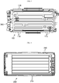
- Fig. 1 is an assembled perspective view schematically showing a battery pack according to an embodiment of the present disclosure
- Fig. 2 is an exploded perspective view of Fig. 1
- Fig. 3 is a top view schematically showing the configuration of a cell assembly 100, in the configuration of Fig. 1
- Fig. 4 is a top view schematically showing the configuration of a pack housing 200, in the configuration of Fig. 1 .
- a battery pack according to the present disclosure includes a cell assembly 100 and a pack housing 200.
- the cell assembly 100 includes a plurality of secondary batteries.
- the plurality of secondary batteries may be pouch-type secondary batteries, and such pouch-type secondary batteries may configure the cell assembly 100 in a state of being stacked in one direction, for example vertically on the figures.
- the cell assembly 100 may include a stacking frame for stacking a plurality of secondary batteries.
- the stacking frame is a component used for stacking secondary batteries, and the stacking frame may hold secondary batteries to prevent shaking of the secondary batteries, and many stacking frames may be stacked with each other to guide assembling of secondary batteries.
- the stacking frame may also be called with various terms, for example a cartridge, and may have a rectangular ring shape with a hollow center. In this case, four edges of the stacking frame may be located at the outer circumference of a pouch-type secondary battery, respectively.
- the cell assembly 100 has an outer protrusion 110 formed at an outer side surface thereof to extend vertically.
- the cell assembly 100 has the outer protrusion 110 formed at the outer side surface thereof to protrude in an outer direction of the cell assembly 100, and the outer protrusion 110 may be formed to extend long in a direction perpendicular to the ground.
- At least two outer protrusions 110 may be formed at the side surface of the cell assembly 100. If a plurality of outer protrusions 110 are formed at the outer surface of the cell assembly 100 as described above, the rigidity of the cell assembly 100 may be improved. Therefore, even though impacts or vibrations are applied from the outside of the cell assembly 100 to the cell assembly 100, it is possible to eliminate, or at least reduce, a damage of the cell assembly 100.
- the pack housing 200 An empty space is formed in the pack housing 200, and the cell assembly 100 may be accommodated in the inner space. Since the pack housing 200 may play a role of an exterior of the battery pack, the pack housing 200 may give structural stability to the battery pack and protect components such as the cell assembly 100 accommodated therein against external physical factors such as impacts or substances. For this, the pack housing 200 may be made of metal material such as steel.
- the pack housing 200 has an inner protrusion 210 formed at an inner side surface thereof to extend vertically.
- the pack housing 200 may have the inner protrusion 210 formed at the side surface of the inner space, in which the cell assembly 100 is accommodated, to protrude inwards, and the inner protrusion 210 may be formed to extend long in a direction perpendicular to the ground.
- the rigidity of the pack housing 200 may be improved. Therefore, even though impacts or vibrations are applied from the outside or inside of the pack housing 200 to the pack housing 200, it is possible to eliminate, or at least reduce, a damage of the pack housing 200.
- the pack housing 200 may have a plurality of inner protrusions 210, and in this case, the pack housing 200 may have more improved rigidity.
- the outer protrusion 110 of the cell assembly and the inner protrusion 210 of the pack housing may be inserted and coupled to each other by means of sliding. This will be described in more detail with reference to Figs. 5 to 9 .
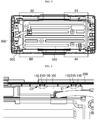
- Fig. 5 is a top view showing the configuration of Fig. 1
- Figs. 6 to 9 are enlarged view showing portions B1 to B4 of Fig. 5 , respectively.
- the inner protrusion 210 of the pack housing may be inserted between two or more adjacent outer protrusions 110, among the outer protrusions 110 of the cell assembly, so that the outer protrusion 110 and the inner protrusion 210 are coupled to each other.
- At least some outer protrusions 110 may be arranged so that two adjacent outer protrusions 110 are spaced by a predetermined distance to form a groove between them.
- the inner protrusion 210 of the pack housing may be inserted into the groove formed between two adjacent outer protrusions 110.
- the groove between the outer protrusions 110 is formed to extend long in a vertical direction, and the inner protrusion 210 inserted into the groove is also formed to extend long in a vertical direction. For this reason, the inner protrusion 210 may be inserted into the groove between the outer protrusions 110 in a sliding way.
- the inner protrusion 210 of the pack housing slides in a state of being fitted into the groove between the outer protrusions 110 of the cell assembly, so that the outer protrusions 110 and the inner protrusion 210 are coupled to each other by insertion.
- the cell assembly 100 may be inserted into the inner accommodation space of the pack housing 200 in a state where the inner protrusion 210 of the pack housing is fitted into the groove between the outer protrusions 110 of the cell assembly, and thus the outer protrusions 110 and the inner protrusion 210 may serve as a guide while the cell assembly 100 is being accommodated into the pack housing 200.
- a spacing distance between two outer protrusions 110 forming a groove may be equal to or greater than a lateral length of the inner protrusion 210 so that the inner protrusion 210 of the pack housing may be easily inserted into the groove.
- the spacing distance between the outer protrusions 110 may not be seriously great, so that coupling locations of the inner protrusion 210 and the outer protrusions 110 may be easily set.
- the spacing distance between two outer protrusions 110 forming a groove may be one time or more and two time or less of the lateral length of the inner protrusion 210 inserted therein.
- the coupling configuration of the outer protrusion 110 and the inner protrusion 210 may be provided in plural at a single battery pack, as shown in Figs. 5 to 9 .
- the groove between two outer protrusions 110 into which the inner protrusion 210 of the pack housing is to be inserted may be two or more at a single cell assembly 100, as indicated by C1 to C7 in the figures, and the inner protrusion 210 inserted into the grooves between a plurality of outer protrusions 110 may also be two or more at a single pack housing 200.
- the outer protrusion 110 and the inner protrusion 210 may be configured to contact each other at two or more portions.
- both sides of the inner protrusion 210 may contact two outer protrusions 110 forming the groove, respectively.
- a left end of the inner protrusion 210 may come into contact with a right side of the outer protrusion 110 located at a left side
- a right end of the inner protrusion 210 may come into contact with a left side of the outer protrusion 110 located at a right side.
- the insertion location of the cell assembly 100 may not be changed but be fixed to a single point. Therefore, the insertion location of the cell assembly 100 with respect to the pack housing 200 may be more accurate, and after the cell assembly 100 is inserted, it is possible to prevent the cell assembly 100 from moving in the pack housing 200. Therefore, while a battery pack is being fabricated or a fabricated battery pack is being used, even though vibrations or impacts are applied to the battery pack, the cell assembly 100 does not move, and thus it can be effectively prevented that the assembling location of the cell assembly 100 is in disorder or the battery pack is damaged.
- the contacting configuration of the outer protrusion 110 and the inner protrusion 210 may also be applied even though the inner protrusion 210 of the pack housing is not inserted into the groove between the outer protrusions 110 of the cell assembly.
- a single outer protrusion 110 and a single inner protrusion 210 may come into contact with each other in a direction of the side surface.
- a left portion of the outer protrusion 110 of the cell assembly may come into contact with a right portion of the inner protrusion 210 of the pack housing.
- the movement of the cell assembly 100 is restricted just in one direction, and thus the movement in the other direction may be restricted by using another contacting configuration.
- the contacting configuration of the outer protrusion 110 and the inner protrusion 210 at the portion D1 may restrict a movement of the cell assembly 100 in a left direction
- the contacting configuration of the outer protrusion 110 and the inner protrusion 210 at the portion C3 may restrict a movement of the cell assembly 100 in a right direction.
- the outer protrusion 110 of the cell assembly may come into contact with the inner side surface of the pack housing 200, and the inner protrusion 210 of the pack housing may come into contact with the outer side surface of the cell assembly 100.
- an outer end (an upper end in Fig. 6 ) of the outer protrusion 110 formed at the cell assembly 100 may come into contact with an inner side surface (a lower surface in Fig. 6 ) of the pack housing 200.
- an inner end (a lower surface in Fig. 6 ) of the inner protrusion 210 of the pack housing may come into contact with an outer surface (an upper surface in Fig. 6 ) of the cell assembly 100.
- the assembling location of the pack housing 200 and the cell assembly 100 becomes more accurate, and the movement of the cell assembly 100 accommodated in the pack housing 200 is restricted, thereby preventing the battery pack from being damaged.
- a movement of the cell assembly 100 in an inner and outer direction may be restricted.
- the inner protrusion 210 of the pack housing may be formed at both side surfaces which have a great length and face each other, among inner side surfaces of the pack housing 200.
- the pack housing 200 may be formed to have a rectangular shape, when being observed from the above, and at this time, the inner protrusion 210 may be formed at two long sides (upper and lower sides in Fig. 3 ) facing each other.
- the outer protrusion 110 of the cell assembly may also be formed at two long sides to correspond to the inner protrusion 210.
- more protrusions may be formed at the pack housing 200 and the cell assembly 100. Therefore, the pack housing 200 and the cell assembly 100 may ensure more sufficient rigidity, and protrusions serving as a guide are coupled at more portions, which may facilitate easier assembling of the pack housing 200 and the cell assembly 100.
- the inner protrusion 210 of the pack housing and/or the outer protrusion 110 of the cell assembly may have a protrusion length which gradually increases from an upper portion to a lower portion thereof, at least partially. This will be described in more detail with reference to Fig. 10 .
- Fig. 10 is an enlarged view schematically showing a portion A of Fig. 2 .
- a protrusion length at an upper portion of the inner protrusion 210 of the pack housing 200 may be assumed as LI, and the inner protrusion 210 may be formed to have a gradually increasing protrusion length in a downward direction. Therefore, at a predetermined point, the inner protrusion 210 may have a protrusion length of L2, and at this time, the following relation is obtained: L2>L1.
- the cell assembly 100 may include ducts provided at both side surfaces thereof so that fluid may flow into or out of the secondary battery.
- the cell assembly 100 may have ducts respectively at a left surface (an upper side in Fig. 3 ) and a right surface (a lower side in Fig. 3 ).
- the duct is a component for allowing fluid to flow into or out of a secondary battery located in the cell assembly 100. Therefore, the duct has an empty space therein to serve as a channel, and also has an inlet for introducing fluid into the empty space or an outlet for discharging fluid from the empty space.
- the secondary battery provided in the cell assembly 100 may exchange heat with external fluid, for example external air, out of the battery pack through the duct. Therefore, the cell assembly 100 may allow external air to be introduced into the cell assembly 100 through the inlet duct so that external air may flow around the secondary battery, and thus the external air may exchange heat with the secondary battery so that the secondary battery is cooled. After that, the air heated while flowing around the secondary battery may be discharged out of the cell assembly 100 through the outlet duct.
- external fluid for example external air
- the outer protrusion 110 of the cell assembly may be provided at an outer surface of the duct.
- the cell assembly 100 may have improved rigidity with respect to the ducts.
- the cell assembly 100 may have somewhat weak rigidity thereat.
- the outer protrusion 110 is formed at the outer portion of the duct, the protrusion may improve rigidity of the duct. Therefore, the cell assembly 100 may ensure stable rigidity as a whole, and thus it is possible to prevent the cell assembly 100 from being damaged due to external vibrations or impacts.
- the outlet and the inlet of the ducts may be formed to protrude from the cell assembly 100 upwards and outwards.
- the cell assembly 100 is accommodated in the inner space of the pack housing 200, and for ensuring fluid to stably flow in or out through the duct, the outlet and the inlet of the duct may be exposed out of the pack housing 200. Therefore, the outlet and the inlet of the duct may be configured to protrude higher than the upper portion of the cell assembly 100 as shown in Fig. 2 , and also to protrude broader than the side surface of the cell assembly 100 as shown in Fig. 3 .
- the pack housing 200 may have a placing portion 220 formed at an upper portion of the side surface thereof where the inner protrusion 210 is formed, so that the outlet and the inlet of the duct are placed thereon. Therefore, the outlet and the inlet of the duct may be placed on the placing portion 220 of the pack housing 200, and thus the outlet and the inlet of the duct may be stably supported upwards.
- the configuration where the inner protrusion 210 of the pack housing and the outer protrusion 110 of the cell assembly are inserted and coupled to each other may guide an accommodation location of the cell assembly 100 in the inner space of the pack housing 200, the outlet and the inlet of the duct may be accurately placed on the placing portion 220 of the pack housing 200.
- the present disclosure is not limited thereto.
- the battery pack according to the present disclosure may also be configured so that a groove is formed between two inner protrusions 210 provided at the pack housing 200, and the outer protrusion 110 of the cell assembly is inserted into the groove.
- the features explained above based on the configuration where the inner protrusion 210 is inserted between the outer protrusions 110 may also be applied to a configuration where the outer protrusion 110 is inserted between the inner protrusions 210.
- the pack housing 200 may further include a lid for covering the open upper portion.
- the battery pack according to the present disclosure may further include a sensing assembly 300.
- the sensing assembly 300 may be provided at one side of the cell assembly 100 to sense a voltage of a secondary battery included in the cell assembly 100.
- the sensing assembly 300 may be respectively connected to both ends of every secondary battery provided at the cell assembly 100 to sense a voltage of every secondary battery.
- the battery pack according to the present disclosure may further include an electronic component plate at an upper portion of the sensing assembly 300.
- the electronic component plate may have a plate shape on which electronic components are mounted.
- the electronic components may include a Battery Management System (BMS), a current sensor, a relay, a fuse or the like.
- BMS Battery Management System
- the battery pack according to the present disclosure may be applied to a vehicle such as an electric vehicle and a hybrid vehicle.
- the vehicle according to the present disclosure may include the battery pack according to the present disclosure as described above.
- the battery pack according to the present disclosure may be easily assembled and not easily damaged due to vibrations or impacts, and thus the battery pack according to the present disclosure may be more effectively applied to a vehicle which may be frequently exposed to vibrations or impacts.
Landscapes
- Chemical & Material Sciences (AREA)
- General Chemical & Material Sciences (AREA)
- Chemical Kinetics & Catalysis (AREA)
- Electrochemistry (AREA)
- Engineering & Computer Science (AREA)
- Manufacturing & Machinery (AREA)
- Sustainable Development (AREA)
- Life Sciences & Earth Sciences (AREA)
- Sustainable Energy (AREA)
- Power Engineering (AREA)
- Transportation (AREA)
- Mechanical Engineering (AREA)
- Aviation & Aerospace Engineering (AREA)
- Inorganic Chemistry (AREA)
- Microelectronics & Electronic Packaging (AREA)
- Battery Mounting, Suspending (AREA)
Claims (11)
- Batteriepack, umfassend:eine Zellenanordnung (100), umfassend eine Mehrzahl von Sekundärbatterien, welche vertikal gestapelt sind und äußere Vorsprünge (110) aufweisen, welche an einer äußeren Seitenfläche davon gebildet sind, um sich vertikal zu erstrecken; undein Packgehäuse (200), welches dazu eingerichtet ist, einen Innenraum aufzuweisen, in welchem die Zellenanordnung aufgenommen ist, wobei das Packgehäuse innere Vorsprünge (210) aufweist, welche an einer inneren Seitenfläche davon gebildet sind, um nach innen vorzustehen und sich vertikal zu erstrecken,wobeidie Zellenanordnung Leitungen aufweist, welche an beiden Seitenflächen davon bereitgestellt sind, so dass Fluid in eine Sekundärbatterie hinein oder aus ihr heraus strömt, und die äußeren Vorsprünge an äußeren Seitenflächen der Leitungen gebildet sind;die äußeren Vorsprünge der Zellenanordnung mit der inneren Seitenfläche des Packgehäuses in Kontakt kommen und die inneren Vorsprünge des Packgehäuses mit der äußeren Seitenfläche der Zellenanordnung in Kontakt kommen; unddas Packgehäuse dazu gebildet ist, eine rechteckige Form aufzuweisen, wenn es von oben betrachtet wird, und die inneren Vorsprünge an den beiden langen Seiten des Packgehäuses gebildet sind, welche zueinander weisen, aus inneren Seitenflächen davon.
- Batteriepack nach Anspruch 1,
wobei die äußeren Vorsprünge und die inneren Vorsprünge dazu eingerichtet sind, mittels Gleitens eingesetzt und miteinander gekoppelt zu sein. - Batteriepack nach Anspruch 2,
wobei der innere Vorsprung des Packgehäuses zwischen zwei benachbarten äußeren Vorsprüngen (110) aus den äußeren Vorsprüngen der Zellenanordnung eingesetzt ist. - Batteriepack nach Anspruch 2,
wobei der äußere Vorsprung der Zellenanordnung zwischen zwei benachbarten inneren Vorsprüngen aus den inneren Vorsprüngen des Packgehäuses eingesetzt ist. - Batteriepack nach Anspruch 2,
wobei die eingesetzte und gekoppelte Konfiguration der äußeren Vorsprünge und der inneren Vorsprünge mehrfach bereitgestellt ist. - Batteriepack nach Anspruch 2,
wobei beide Seiten der äußeren Vorsprünge oder der inneren Vorsprünge in Kontakt mit zwei inneren Vorsprüngen oder zwei äußeren Vorsprüngen kommen, welche die Nut bilden. - Batteriepack nach Anspruch 1,
wobei der innere Vorsprung dazu eingerichtet ist, einen Abschnitt aufzuweisen, welcher eine graduell zunehmende Vorsprungslänge von einem oberen Abschnitt zu einem unteren Abschnitt davon aufweist. - Batteriepack nach Anspruch 1,
wobei ein Auslass und ein Einlass der Leitung dazu gebildet sind, nach oben und nach außen an der Zellenanordnung vorzustehen, und
wobei das Packgehäuse einen Platzierungsabschnitt (220) umfasst, welcher an einem oberen Abschnitt der Seitenfläche gebildet ist, an welcher der innere Vorsprung gebildet ist, so dass der Auslass und der Einlass der Leitung daran platziert sind. - Batteriepack nach Anspruch 1, ferner umfassend:
eine Erfassungsanordnung (300), welche an einer Seite der Zellenanordnung bereitgestellt ist, um eine Spannung der Sekundärbatterie zu erfassen. - Batteriepack nach Anspruch 1, ferner umfassend:
eine Elektronikkomponenten-Platte, welche an einem oberen Abschnitt der Erfassungsanordnung bereitgestellt ist, um ein Batterie-Managementsystem (BMS) zu umfassen. - Fahrzeug, umfassend den Batteriepack nach einem der Ansprüche 1 bis 10.
Priority Applications (1)
| Application Number | Priority Date | Filing Date | Title |
|---|---|---|---|
| PL14865214T PL3076455T3 (pl) | 2013-11-29 | 2014-11-26 | Pakiet akumulatorów |
Applications Claiming Priority (2)
| Application Number | Priority Date | Filing Date | Title |
|---|---|---|---|
| KR1020130147810A KR101807113B1 (ko) | 2013-11-29 | 2013-11-29 | 배터리 팩 |
| PCT/KR2014/011423 WO2015080465A1 (ko) | 2013-11-29 | 2014-11-26 | 배터리 팩 |
Publications (3)
| Publication Number | Publication Date |
|---|---|
| EP3076455A1 EP3076455A1 (de) | 2016-10-05 |
| EP3076455A4 EP3076455A4 (de) | 2017-05-10 |
| EP3076455B1 true EP3076455B1 (de) | 2018-08-15 |
Family
ID=53199356
Family Applications (1)
| Application Number | Title | Priority Date | Filing Date |
|---|---|---|---|
| EP14865214.2A Active EP3076455B1 (de) | 2013-11-29 | 2014-11-26 | Batteriepack |
Country Status (6)
| Country | Link |
|---|---|
| US (2) | US10367179B2 (de) |
| EP (1) | EP3076455B1 (de) |
| KR (1) | KR101807113B1 (de) |
| CN (1) | CN105794016B (de) |
| PL (1) | PL3076455T3 (de) |
| WO (1) | WO2015080465A1 (de) |
Families Citing this family (24)
| Publication number | Priority date | Publication date | Assignee | Title |
|---|---|---|---|---|
| KR102054413B1 (ko) * | 2015-06-09 | 2019-12-10 | 주식회사 엘지화학 | 배터리 팩 |
| WO2017104878A1 (ko) * | 2015-12-18 | 2017-06-22 | 주식회사 엘지화학 | 배터리 팩 |
| KR102167632B1 (ko) * | 2016-09-19 | 2020-10-19 | 주식회사 엘지화학 | 배터리 팩 및 이러한 배터리 팩을 포함하는 자동차 |
| US11569545B2 (en) | 2017-01-27 | 2023-01-31 | Cps Technology Holdings Llc | Battery housing |
| US11936032B2 (en) | 2017-06-09 | 2024-03-19 | Cps Technology Holdings Llc | Absorbent glass mat battery |
| CN117393868A (zh) | 2017-06-09 | 2024-01-12 | Cps 科技控股有限公司 | 铅酸电池 |
| KR102267586B1 (ko) * | 2017-07-06 | 2021-06-21 | 주식회사 엘지에너지솔루션 | 배터리 모듈 |
| KR102066198B1 (ko) | 2017-07-13 | 2020-01-14 | 주식회사 엘지화학 | 배터리 팩 |
| KR102267587B1 (ko) * | 2017-07-17 | 2021-06-21 | 주식회사 엘지에너지솔루션 | 배터리 팩 |
| CN108091804B (zh) * | 2018-01-31 | 2023-07-28 | 淮南市通霸蓄电池有限公司 | 一种防爆特殊型电源装置 |
| KR102071134B1 (ko) * | 2018-04-13 | 2020-01-29 | ㈜ 에이치엠지 | 자동차의 배터리 냉각장치 |
| KR102255487B1 (ko) * | 2018-07-03 | 2021-07-21 | 주식회사 엘지에너지솔루션 | 배터리 모듈, 이러한 배터리 모듈을 포함하는 배터리 팩 및 이러한 배터리 팩을 포함하는 자동차 |
| KR102722638B1 (ko) * | 2019-03-26 | 2024-10-25 | 주식회사 엘지에너지솔루션 | 전지 모듈 및 그 제조 방법 |
| KR102772385B1 (ko) * | 2019-08-07 | 2025-02-25 | 주식회사 엘지에너지솔루션 | 표면 요철 구조를 갖는 전지팩 커버 및 이를 포함하는 전지팩 |
| KR102952072B1 (ko) * | 2020-02-25 | 2026-04-10 | 삼성에스디아이 주식회사 | 전지 팩 |
| JP7621846B2 (ja) * | 2021-03-22 | 2025-01-27 | 愛三工業株式会社 | 電池パック |
| FR3123158A1 (fr) * | 2021-05-21 | 2022-11-25 | Faurecia Systemes D'echappement | Batterie de stockage d’électricité et procédé de fabrication correspondant |
| CN215989048U (zh) * | 2021-10-13 | 2022-03-08 | 宁德时代新能源科技股份有限公司 | 电池包和车辆 |
| KR102705534B1 (ko) * | 2021-10-22 | 2024-09-11 | 주식회사 코리아하이텍 | 배터리 케이스 |
| WO2024085555A1 (ko) | 2022-10-18 | 2024-04-25 | 주식회사 엘지에너지솔루션 | 수납된 전지 모듈의 고정력이 향상된 전지 팩 및 이를 포함하는 디바이스 |
| KR20240054174A (ko) | 2022-10-18 | 2024-04-25 | 주식회사 엘지에너지솔루션 | 수납된 전지 모듈의 고정력이 향상된 전지 팩 및 이를 포함하는 디바이스 |
| US20240186638A1 (en) * | 2022-12-06 | 2024-06-06 | Milwaukee Electric Tool Corporation | Battery pack assembly |
| KR20240096115A (ko) * | 2022-12-19 | 2024-06-26 | 주식회사 엘지에너지솔루션 | 전지 모듈 및 이의 제조 방법 |
| KR102877952B1 (ko) * | 2023-10-17 | 2025-10-31 | 주식회사 코뱃 | 소형 ev용 배터리 팩 |
Family Cites Families (11)
| Publication number | Priority date | Publication date | Assignee | Title |
|---|---|---|---|---|
| US6265091B1 (en) * | 1997-06-06 | 2001-07-24 | Johnson Controls Technology Company | Modular electric storage battery |
| US6410185B1 (en) * | 1999-02-15 | 2002-06-25 | Sony Corporation | Battery device for loading on moving body |
| JP4631118B2 (ja) * | 1999-02-15 | 2011-02-16 | ソニー株式会社 | 移動体搭載用バッテリ装置 |
| US6773846B2 (en) | 2002-08-19 | 2004-08-10 | Allis Electric Co., Ltd. | Mobile rack type battery box for UPS system |
| KR100709868B1 (ko) * | 2004-09-22 | 2007-04-23 | 삼성에스디아이 주식회사 | 이차전지용 팩 케이스 |
| KR100892046B1 (ko) | 2006-09-18 | 2009-04-07 | 주식회사 엘지화학 | 전지모듈 및 그것을 포함하고 있는 중대형 전지팩 |
| KR100875579B1 (ko) * | 2007-10-10 | 2008-12-23 | 주식회사 효성 | 연료전지 스택 체결장치 |
| KR101057563B1 (ko) * | 2009-07-01 | 2011-08-17 | 삼성에스디아이 주식회사 | 배터리 팩 |
| US9537173B2 (en) * | 2010-02-10 | 2017-01-03 | Lg Chem, Ltd. | Pouch type lithium secondary battery |
| KR101898292B1 (ko) | 2012-04-25 | 2018-09-12 | 에스케이이노베이션 주식회사 | 전지팩 어셈블리 |
| KR101501026B1 (ko) | 2012-05-04 | 2015-03-10 | 주식회사 엘지화학 | 우수한 냉각 효율성과 콤팩트한 구조의 전지모듈 |
-
2013
- 2013-11-29 KR KR1020130147810A patent/KR101807113B1/ko active Active
-
2014
- 2014-11-26 PL PL14865214T patent/PL3076455T3/pl unknown
- 2014-11-26 WO PCT/KR2014/011423 patent/WO2015080465A1/ko not_active Ceased
- 2014-11-26 CN CN201480064976.3A patent/CN105794016B/zh active Active
- 2014-11-26 EP EP14865214.2A patent/EP3076455B1/de active Active
- 2014-11-26 US US15/030,662 patent/US10367179B2/en active Active
-
2019
- 2019-06-12 US US16/439,222 patent/US11133551B2/en active Active
Non-Patent Citations (1)
| Title |
|---|
| None * |
Also Published As
| Publication number | Publication date |
|---|---|
| WO2015080465A1 (ko) | 2015-06-04 |
| CN105794016A (zh) | 2016-07-20 |
| US20160254505A1 (en) | 2016-09-01 |
| US11133551B2 (en) | 2021-09-28 |
| EP3076455A4 (de) | 2017-05-10 |
| PL3076455T3 (pl) | 2018-12-31 |
| EP3076455A1 (de) | 2016-10-05 |
| CN105794016B (zh) | 2019-02-19 |
| US20190296292A1 (en) | 2019-09-26 |
| KR20150062800A (ko) | 2015-06-08 |
| US10367179B2 (en) | 2019-07-30 |
| KR101807113B1 (ko) | 2017-12-08 |
Similar Documents
| Publication | Publication Date | Title |
|---|---|---|
| US11133551B2 (en) | Battery pack | |
| EP3550661B1 (de) | Batteriemodul | |
| EP3136497B1 (de) | Batteriemodul mit wasserkühlungsstruktur | |
| US10243193B2 (en) | Battery pack | |
| KR101658594B1 (ko) | 이차 전지용 프레임 및 이를 포함하는 배터리 모듈 | |
| EP3093908B1 (de) | Batteriepack | |
| US20190189979A1 (en) | Battery module | |
| EP3035434A1 (de) | Batteriemodul | |
| EP3091591B1 (de) | Batteriepack | |
| EP3007265A1 (de) | Sekundärbatterierahmen und batteriemodul damit | |
| KR101806412B1 (ko) | 이차 전지용 카트리지 및 이를 포함하는 배터리 모듈 | |
| KR101702505B1 (ko) | 배터리 모듈 및 이를 포함하는 배터리 팩 | |
| CN207731960U (zh) | 电池模块、包括这种电池模块的电池组及包括这种电池组的汽车 | |
| KR20150097019A (ko) | 배터리 모듈 및 이를 포함하는 배터리 팩 | |
| KR101847680B1 (ko) | 배터리 팩 | |
| KR101760404B1 (ko) | 배터리 모듈 및 이를 포함하는 배터리 팩 | |
| KR101760399B1 (ko) | 이차 전지용 카트리지 및 이를 포함하는 배터리 모듈 | |
| KR101760402B1 (ko) | 배터리 모듈 및 이를 포함하는 배터리 팩 | |
| EP4636921A1 (de) | Batteriepack | |
| KR101764837B1 (ko) | 배터리 모듈 및 이를 포함하는 배터리 팩 | |
| KR101807114B1 (ko) | 배터리 모듈 및 이를 포함하는 배터리 팩 |
Legal Events
| Date | Code | Title | Description |
|---|---|---|---|
| PUAI | Public reference made under article 153(3) epc to a published international application that has entered the european phase |
Free format text: ORIGINAL CODE: 0009012 |
|
| 17P | Request for examination filed |
Effective date: 20160517 |
|
| AK | Designated contracting states |
Kind code of ref document: A1 Designated state(s): AL AT BE BG CH CY CZ DE DK EE ES FI FR GB GR HR HU IE IS IT LI LT LU LV MC MK MT NL NO PL PT RO RS SE SI SK SM TR |
|
| AX | Request for extension of the european patent |
Extension state: BA ME |
|
| DAX | Request for extension of the european patent (deleted) | ||
| A4 | Supplementary search report drawn up and despatched |
Effective date: 20170412 |
|
| RIC1 | Information provided on ipc code assigned before grant |
Ipc: H01M 2/10 20060101AFI20170404BHEP Ipc: H01M 10/42 20060101ALI20170404BHEP Ipc: H01M 10/48 20060101ALI20170404BHEP Ipc: B60L 11/18 20060101ALI20170404BHEP Ipc: H01M 2/02 20060101ALI20170404BHEP |
|
| STAA | Information on the status of an ep patent application or granted ep patent |
Free format text: STATUS: EXAMINATION IS IN PROGRESS |
|
| 17Q | First examination report despatched |
Effective date: 20171219 |
|
| GRAP | Despatch of communication of intention to grant a patent |
Free format text: ORIGINAL CODE: EPIDOSNIGR1 |
|
| STAA | Information on the status of an ep patent application or granted ep patent |
Free format text: STATUS: GRANT OF PATENT IS INTENDED |
|
| INTG | Intention to grant announced |
Effective date: 20180604 |
|
| GRAS | Grant fee paid |
Free format text: ORIGINAL CODE: EPIDOSNIGR3 |
|
| GRAA | (expected) grant |
Free format text: ORIGINAL CODE: 0009210 |
|
| STAA | Information on the status of an ep patent application or granted ep patent |
Free format text: STATUS: THE PATENT HAS BEEN GRANTED |
|
| AK | Designated contracting states |
Kind code of ref document: B1 Designated state(s): AL AT BE BG CH CY CZ DE DK EE ES FI FR GB GR HR HU IE IS IT LI LT LU LV MC MK MT NL NO PL PT RO RS SE SI SK SM TR |
|
| REG | Reference to a national code |
Ref country code: CH Ref legal event code: EP Ref country code: GB Ref legal event code: FG4D Ref country code: AT Ref legal event code: REF Ref document number: 1030794 Country of ref document: AT Kind code of ref document: T Effective date: 20180815 |
|
| REG | Reference to a national code |
Ref country code: IE Ref legal event code: FG4D |
|
| REG | Reference to a national code |
Ref country code: DE Ref legal event code: R096 Ref document number: 602014030653 Country of ref document: DE |
|
| REG | Reference to a national code |
Ref country code: NL Ref legal event code: MP Effective date: 20180815 |
|
| REG | Reference to a national code |
Ref country code: LT Ref legal event code: MG4D |
|
| REG | Reference to a national code |
Ref country code: AT Ref legal event code: MK05 Ref document number: 1030794 Country of ref document: AT Kind code of ref document: T Effective date: 20180815 |
|
| PG25 | Lapsed in a contracting state [announced via postgrant information from national office to epo] |
Ref country code: FI Free format text: LAPSE BECAUSE OF FAILURE TO SUBMIT A TRANSLATION OF THE DESCRIPTION OR TO PAY THE FEE WITHIN THE PRESCRIBED TIME-LIMIT Effective date: 20180815 Ref country code: SE Free format text: LAPSE BECAUSE OF FAILURE TO SUBMIT A TRANSLATION OF THE DESCRIPTION OR TO PAY THE FEE WITHIN THE PRESCRIBED TIME-LIMIT Effective date: 20180815 Ref country code: GR Free format text: LAPSE BECAUSE OF FAILURE TO SUBMIT A TRANSLATION OF THE DESCRIPTION OR TO PAY THE FEE WITHIN THE PRESCRIBED TIME-LIMIT Effective date: 20181116 Ref country code: NO Free format text: LAPSE BECAUSE OF FAILURE TO SUBMIT A TRANSLATION OF THE DESCRIPTION OR TO PAY THE FEE WITHIN THE PRESCRIBED TIME-LIMIT Effective date: 20181115 Ref country code: BG Free format text: LAPSE BECAUSE OF FAILURE TO SUBMIT A TRANSLATION OF THE DESCRIPTION OR TO PAY THE FEE WITHIN THE PRESCRIBED TIME-LIMIT Effective date: 20181115 Ref country code: NL Free format text: LAPSE BECAUSE OF FAILURE TO SUBMIT A TRANSLATION OF THE DESCRIPTION OR TO PAY THE FEE WITHIN THE PRESCRIBED TIME-LIMIT Effective date: 20180815 Ref country code: RS Free format text: LAPSE BECAUSE OF FAILURE TO SUBMIT A TRANSLATION OF THE DESCRIPTION OR TO PAY THE FEE WITHIN THE PRESCRIBED TIME-LIMIT Effective date: 20180815 Ref country code: LT Free format text: LAPSE BECAUSE OF FAILURE TO SUBMIT A TRANSLATION OF THE DESCRIPTION OR TO PAY THE FEE WITHIN THE PRESCRIBED TIME-LIMIT Effective date: 20180815 Ref country code: IS Free format text: LAPSE BECAUSE OF FAILURE TO SUBMIT A TRANSLATION OF THE DESCRIPTION OR TO PAY THE FEE WITHIN THE PRESCRIBED TIME-LIMIT Effective date: 20181215 Ref country code: AT Free format text: LAPSE BECAUSE OF FAILURE TO SUBMIT A TRANSLATION OF THE DESCRIPTION OR TO PAY THE FEE WITHIN THE PRESCRIBED TIME-LIMIT Effective date: 20180815 |
|
| PG25 | Lapsed in a contracting state [announced via postgrant information from national office to epo] |
Ref country code: HR Free format text: LAPSE BECAUSE OF FAILURE TO SUBMIT A TRANSLATION OF THE DESCRIPTION OR TO PAY THE FEE WITHIN THE PRESCRIBED TIME-LIMIT Effective date: 20180815 Ref country code: AL Free format text: LAPSE BECAUSE OF FAILURE TO SUBMIT A TRANSLATION OF THE DESCRIPTION OR TO PAY THE FEE WITHIN THE PRESCRIBED TIME-LIMIT Effective date: 20180815 Ref country code: LV Free format text: LAPSE BECAUSE OF FAILURE TO SUBMIT A TRANSLATION OF THE DESCRIPTION OR TO PAY THE FEE WITHIN THE PRESCRIBED TIME-LIMIT Effective date: 20180815 |
|
| PG25 | Lapsed in a contracting state [announced via postgrant information from national office to epo] |
Ref country code: ES Free format text: LAPSE BECAUSE OF FAILURE TO SUBMIT A TRANSLATION OF THE DESCRIPTION OR TO PAY THE FEE WITHIN THE PRESCRIBED TIME-LIMIT Effective date: 20180815 Ref country code: CZ Free format text: LAPSE BECAUSE OF FAILURE TO SUBMIT A TRANSLATION OF THE DESCRIPTION OR TO PAY THE FEE WITHIN THE PRESCRIBED TIME-LIMIT Effective date: 20180815 Ref country code: RO Free format text: LAPSE BECAUSE OF FAILURE TO SUBMIT A TRANSLATION OF THE DESCRIPTION OR TO PAY THE FEE WITHIN THE PRESCRIBED TIME-LIMIT Effective date: 20180815 Ref country code: EE Free format text: LAPSE BECAUSE OF FAILURE TO SUBMIT A TRANSLATION OF THE DESCRIPTION OR TO PAY THE FEE WITHIN THE PRESCRIBED TIME-LIMIT Effective date: 20180815 Ref country code: IT Free format text: LAPSE BECAUSE OF FAILURE TO SUBMIT A TRANSLATION OF THE DESCRIPTION OR TO PAY THE FEE WITHIN THE PRESCRIBED TIME-LIMIT Effective date: 20180815 |
|
| REG | Reference to a national code |
Ref country code: DE Ref legal event code: R097 Ref document number: 602014030653 Country of ref document: DE |
|
| PG25 | Lapsed in a contracting state [announced via postgrant information from national office to epo] |
Ref country code: DK Free format text: LAPSE BECAUSE OF FAILURE TO SUBMIT A TRANSLATION OF THE DESCRIPTION OR TO PAY THE FEE WITHIN THE PRESCRIBED TIME-LIMIT Effective date: 20180815 Ref country code: SK Free format text: LAPSE BECAUSE OF FAILURE TO SUBMIT A TRANSLATION OF THE DESCRIPTION OR TO PAY THE FEE WITHIN THE PRESCRIBED TIME-LIMIT Effective date: 20180815 Ref country code: SM Free format text: LAPSE BECAUSE OF FAILURE TO SUBMIT A TRANSLATION OF THE DESCRIPTION OR TO PAY THE FEE WITHIN THE PRESCRIBED TIME-LIMIT Effective date: 20180815 |
|
| PLBE | No opposition filed within time limit |
Free format text: ORIGINAL CODE: 0009261 |
|
| STAA | Information on the status of an ep patent application or granted ep patent |
Free format text: STATUS: NO OPPOSITION FILED WITHIN TIME LIMIT |
|
| REG | Reference to a national code |
Ref country code: CH Ref legal event code: PL |
|
| 26N | No opposition filed |
Effective date: 20190516 |
|
| PG25 | Lapsed in a contracting state [announced via postgrant information from national office to epo] |
Ref country code: MC Free format text: LAPSE BECAUSE OF FAILURE TO SUBMIT A TRANSLATION OF THE DESCRIPTION OR TO PAY THE FEE WITHIN THE PRESCRIBED TIME-LIMIT Effective date: 20180815 Ref country code: LU Free format text: LAPSE BECAUSE OF NON-PAYMENT OF DUE FEES Effective date: 20181126 |
|
| REG | Reference to a national code |
Ref country code: BE Ref legal event code: MM Effective date: 20181130 |
|
| REG | Reference to a national code |
Ref country code: IE Ref legal event code: MM4A |
|
| PG25 | Lapsed in a contracting state [announced via postgrant information from national office to epo] |
Ref country code: SI Free format text: LAPSE BECAUSE OF FAILURE TO SUBMIT A TRANSLATION OF THE DESCRIPTION OR TO PAY THE FEE WITHIN THE PRESCRIBED TIME-LIMIT Effective date: 20180815 Ref country code: LI Free format text: LAPSE BECAUSE OF NON-PAYMENT OF DUE FEES Effective date: 20181130 Ref country code: CH Free format text: LAPSE BECAUSE OF NON-PAYMENT OF DUE FEES Effective date: 20181130 |
|
| PG25 | Lapsed in a contracting state [announced via postgrant information from national office to epo] |
Ref country code: IE Free format text: LAPSE BECAUSE OF NON-PAYMENT OF DUE FEES Effective date: 20181126 |
|
| PG25 | Lapsed in a contracting state [announced via postgrant information from national office to epo] |
Ref country code: BE Free format text: LAPSE BECAUSE OF NON-PAYMENT OF DUE FEES Effective date: 20181130 |
|
| PG25 | Lapsed in a contracting state [announced via postgrant information from national office to epo] |
Ref country code: MT Free format text: LAPSE BECAUSE OF NON-PAYMENT OF DUE FEES Effective date: 20181126 |
|
| PG25 | Lapsed in a contracting state [announced via postgrant information from national office to epo] |
Ref country code: TR Free format text: LAPSE BECAUSE OF FAILURE TO SUBMIT A TRANSLATION OF THE DESCRIPTION OR TO PAY THE FEE WITHIN THE PRESCRIBED TIME-LIMIT Effective date: 20180815 |
|
| PG25 | Lapsed in a contracting state [announced via postgrant information from national office to epo] |
Ref country code: PT Free format text: LAPSE BECAUSE OF FAILURE TO SUBMIT A TRANSLATION OF THE DESCRIPTION OR TO PAY THE FEE WITHIN THE PRESCRIBED TIME-LIMIT Effective date: 20180815 |
|
| PG25 | Lapsed in a contracting state [announced via postgrant information from national office to epo] |
Ref country code: HU Free format text: LAPSE BECAUSE OF FAILURE TO SUBMIT A TRANSLATION OF THE DESCRIPTION OR TO PAY THE FEE WITHIN THE PRESCRIBED TIME-LIMIT; INVALID AB INITIO Effective date: 20141126 Ref country code: MK Free format text: LAPSE BECAUSE OF NON-PAYMENT OF DUE FEES Effective date: 20180815 Ref country code: CY Free format text: LAPSE BECAUSE OF FAILURE TO SUBMIT A TRANSLATION OF THE DESCRIPTION OR TO PAY THE FEE WITHIN THE PRESCRIBED TIME-LIMIT Effective date: 20180815 |
|
| REG | Reference to a national code |
Ref country code: DE Ref legal event code: R079 Ref document number: 602014030653 Country of ref document: DE Free format text: PREVIOUS MAIN CLASS: H01M0002100000 Ipc: H01M0050200000 |
|
| P01 | Opt-out of the competence of the unified patent court (upc) registered |
Effective date: 20230512 |
|
| REG | Reference to a national code |
Ref country code: DE Ref legal event code: R081 Ref document number: 602014030653 Country of ref document: DE Owner name: LG ENERGY SOLUTION, LTD., KR Free format text: FORMER OWNER: LG CHEM, LTD., SEOUL, KR |
|
| REG | Reference to a national code |
Ref country code: GB Ref legal event code: 732E Free format text: REGISTERED BETWEEN 20230824 AND 20230831 |
|
| PGFP | Annual fee paid to national office [announced via postgrant information from national office to epo] |
Ref country code: DE Payment date: 20251020 Year of fee payment: 12 |
|
| PGFP | Annual fee paid to national office [announced via postgrant information from national office to epo] |
Ref country code: GB Payment date: 20251023 Year of fee payment: 12 |
|
| PGFP | Annual fee paid to national office [announced via postgrant information from national office to epo] |
Ref country code: FR Payment date: 20251021 Year of fee payment: 12 |
|
| PGFP | Annual fee paid to national office [announced via postgrant information from national office to epo] |
Ref country code: PL Payment date: 20251020 Year of fee payment: 12 |