EP3076349A1 - Management system and management method - Google Patents
Management system and management method Download PDFInfo
- Publication number
- EP3076349A1 EP3076349A1 EP16162012.5A EP16162012A EP3076349A1 EP 3076349 A1 EP3076349 A1 EP 3076349A1 EP 16162012 A EP16162012 A EP 16162012A EP 3076349 A1 EP3076349 A1 EP 3076349A1
- Authority
- EP
- European Patent Office
- Prior art keywords
- command information
- operation command
- management
- heat pump
- management system
- Prior art date
- Legal status (The legal status is an assumption and is not a legal conclusion. Google has not performed a legal analysis and makes no representation as to the accuracy of the status listed.)
- Ceased
Links
Images




Classifications
-
- G—PHYSICS
- G06—COMPUTING OR CALCULATING; COUNTING
- G06Q—INFORMATION AND COMMUNICATION TECHNOLOGY [ICT] SPECIALLY ADAPTED FOR ADMINISTRATIVE, COMMERCIAL, FINANCIAL, MANAGERIAL OR SUPERVISORY PURPOSES; SYSTEMS OR METHODS SPECIALLY ADAPTED FOR ADMINISTRATIVE, COMMERCIAL, FINANCIAL, MANAGERIAL OR SUPERVISORY PURPOSES, NOT OTHERWISE PROVIDED FOR
- G06Q10/00—Administration; Management
- G06Q10/06—Resources, workflows, human or project management; Enterprise or organisation planning; Enterprise or organisation modelling
Definitions
- the present invention relates to a management system and a management method.
- a commodity which is a target for management is delivered to a customer, and then a sales agency performs a management operation on the commodity.
- a sales agency performs a management operation on the commodity.
- the commodity is a water heater and it is difficult to operate the water heater, or a case where a sales agency sells a large number of water heaters and takes charge of the management thereof, a person in charge who is a sales agency may perform management operations remotely. Meanwhile, an associated technique is disclosed in Patent Literature 1.
- Patent Literature 1 PCT International Publication No. WO 2013/118884 .
- a control command for a management operation has to be transmitted to a device (main board) having an air conditioner which is a target for management connected thereto.
- the transmitting side of the control command is required to always ascertain address information on a network of the air conditioner or a device that relays the control command to the air conditioner.
- the present invention provides a management system and a management method which are capable of solving the above-mentioned problem.
- a management system including a management device and a managed device.
- the management device includes an operation command information storage unit that receives and stores operation command information from a manager terminal, and an operation command information transmission unit that transmits the operation command information on the basis of a request for the operation command information.
- the managed device which is an objected device of the management, performs operation control of the device on the basis of the operation command information received from the management device.
- the management system may further include a relay device that transmits the request to the management device; and an operation command relay unit that receives the operation command information from the management device and transmits the received information to the managed device.
- the relay device may transmit the request to the management device periodically or at a predetermined time.
- the operation command information transmission unit of the management device may transmit operation command information having a highest degree of priority among items of the operation command information for the managed device.
- a magnitude of the degree of priority may be determined on the basis of a registration time of the operation command information.
- a magnitude of the degree of priority may be determined on the basis of a manager having the operation command information registered therewith.
- the managed device may be constituted by a plurality of the managed devices, the operation command information may be operation command information of each of the plurality of managed devices, and the operation control unit of each of the plurality of managed devices which are targets for management may acquire an operation command corresponding to the device on the basis of the operation command information and performs operation control.
- a management method in a management system provided with a management device and a managed device, the method including: causing an operation command information storage unit of the management device to receive and store operation command information from a manager terminal; causing an operation command information transmission unit of the management device to transmit the operation command information on the basis of a request for the operation command information; and causing an operation control unit of the managed device to perform operation control of the device on the basis of the operation command information received from the management device.
- the management system and the management method described above it is not necessary for a manager device to have a direct access to a managed device, and thus it not necessary to ascertain an address on a network of the managed device at all times. Therefore, the system can be constructed at a low cost, and the versatility of the system increases. In addition, the change of design of the system is facilitated.
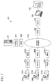
- FIG. 1 is a block diagram illustrating a schematic configuration of a management system 1 according to a first embodiment of the present invention.
- the management system 1 according to the first embodiment of the present invention includes a management server (management device) 11, heat pump devices (managed devices, which are targets for management) 12a to 12c, and manager terminals 13a to 13c.
- the number of heat pump devices included in the management system 1 may be one or more without being limited to three shown in FIG. 1 .
- the number of manager terminals included in the management system 1 may be one or more without being limited to three shown in FIG. 1 .
- the number of manager terminals is the same as the number of heat pump devices.
- the management server 11 is a server that manages the heat pump devices 12a to 12c.
- the management server 11 is capable of being connected to an Internet network 14 through a firewall 21 and a modem 22.
- the heat pump devices 12a to 12c are, for example, water heaters using a heat pump.
- the heat pump devices 12a, 12b, and 12c are capable of being connected to the Internet network 14 through gateways (relay devices) 31a, 31 b, and 31 c, routers 32a, 32b, and 32c, and modems 33a, 33b, and 33c, respectively.
- the number of gateways included in the management system 1 may be one or more without being limited to three shown in FIG. 1 . As shown in FIG. 1 , in the configuration in which a gateway is included for each heat pump device, the number of gateways may be the same with heat pump devices.
- the number of routers included in the management system 1 may be one or more without being limited to three shown in FIG. 1 .
- the number of routers may be the sum of the number of heat pump devices and the number of manager terminals.
- the number of modems included in the management system 1 may be one or more without being limited to three shown in FIG. 1 .
- the number of modems may be the sum of the number of routers and the number of management servers.
- the manager terminals 13a to 13c are terminals that remotely operate the heat pump devices 12a to 12c.
- the manager terminals 13a, 13b, and 13c are capable of being connected to the Internet network 14 through routers 41 a, 41 b, and 41c, and modems 42a, 42b, and 42c, respectively.
- the manager terminals 13a to 13c to be used may include any devices such as a personal computer (PC) and a portable terminal as long as these terminals are capable of being connected to the Internet network 14.
- each of the manager terminals 13a to 13c may be installed on a different place such as a user's house, an agent, or a maintenance company.
- operators 43a to 43c corresponding to managers of the manager terminals 13a to 13c include users of the heat pump devices 12a to 12c, operators of agents of the devices, operators of maintenance companies of the heat pump devices 12a to 12c, or the like.
- the operators 43a to 43c give operation inputs to the manager terminals 13a to 13c.
- command files operation command information
- the management server 11 receives the command files from the manager terminals 13a to 13c, the management server stores these command files. Meanwhile, the number of operators may be one or more without being particularly limited.
- Each of the gateways 31 a to 31 c of the heat pump devices 12a to 12c has access to the management server 11 for each predetermined time or at a predetermined time (or periodically), and acquires a command file which is used for operating the device to the management server 11.
- Each of the gateways 31 a to 31 c sets an operation of each of the heat pump devices 12a to 12c on the basis of the acquired command file.
- the management system 1 generates the command files in the manager terminals 13a to 13c on the basis of the operation inputs, and transmits these command files to the management server 11.
- the management server 11 stores these command files.
- Each of the gateways 31 a to 31c of the heat pump devices 12a to 12c has access to the management server 11 for each predetermined time or at a predetermined time.
- the gateways 31 a to 31 c download the command files which are used for operating the device, and control operations of the heat pump devices 12a to 12c on the basis of these command files.
- the manager terminals 13a to 13c are not required to have a direct access to the heat pump devices 12a to 12c (or gateways 31 a to 31 c), and may be capable of being connected only to the management server 11.
- the management server 11 is also not required to have a direct access to the heat pump devices 12a to 12c (or gateways 31 a to 31 c), and the gateways 31 a to 31 c may be capable of being connected to the management server 11. Therefore, a dedicated line is not required for constructing the management system 1.
- IP addresses for connecting the manager terminals 13a to 13c or the gateways 31a to 31c to the Internet network 14 may be appropriately acquired using, for example, a dynamic host configuration protocol (DHCP).
- DHCP dynamic host configuration protocol
- a general-purpose PC or a portable terminal can be used as the manager terminals 13a to 13c or the gateways 31a to 31c. Therefore, the system can be constructed at a low cost, and the versatility of the system increases. In addition, the change of design of the system is facilitated.
- FIG. 2 is a functional block diagram based on an operation of the management system 1 according to the first embodiment of the present invention.
- the operation of the management system 1 according to the first embodiment of the present invention will be further described with reference to the functional block diagram of FIG. 2 .
- the Internet network 14, the firewall 21, the modem 22, the routers 32a to 32c, the modems 33a to 33c, the routers 41a to 41c, and the modems 42a to 42c are omitted for the purpose of simplifying description.
- the management system 1 includes the management server 11, the heat pump devices 12a to 12c, and the manager terminals 13a to 13c.
- the gateways 31 a to 31 c are provided, as relays, between the management server 11 and the heat pump devices 12a to 12c.
- the gateways 31a to 31c can be realized by, for example, a PC.
- the management server 11 includes an operation command information storage unit 51, an operation command information transmission unit 52, a request receiving unit 53, and an operation command information retrieval unit 54.
- the operation command information storage unit 51 stores the command files received from the manager terminals 13a to 13c.
- the operation command information transmission unit 52 transmits the command files which are used for operating the device, to the gateways 31 a to 31c of the heat pump devices 12a to 12c.
- the request receiving unit 53 receives a request for the command files from the gateways 31 a to 31 c.
- the operation command information retrieval unit 54 retrieves a desired command file which is used for operating the device, from the command files stored in the operation command information storage unit 51.
- Each of the gateways 31a to 31c of the heat pump devices 12a to 12c includes a request transmission unit 61 and an operation command information receiving unit 62 (operation command relay unit).
- the request transmission unit 61 transmits a request for a command file for operating the device as a target device, to the management server 11.
- the operation command information receiving unit 62 receives the command file which is used for operating the device, from the management server 11.
- Each of the heat pump devices 12a to 12c includes an operation command information analysis unit 81 and an operation control unit 82.
- the operation command information analysis unit 81 analyzes the received command file.
- the operation control unit 82 performs operation control of the device on the basis of information of the command file analyzed by the operation command information analysis unit 81.
- Each of the manager terminals 13a to 13c includes an operation input unit 71 and an operation command information generation unit 72.
- the operation input unit 71 inputs operation information of the heat pump devices 12a to 12c on the basis of the operation screen.
- the operation command information generation unit 72 generates a command file on the basis of the input operation information.
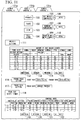
- FIG. 3 is a diagram illustrating an example of an operation screen in the management system according to the first embodiment of the present invention.
- an operation button 101 is a button for performing a hot-water tank operation.
- a pause button 102 is a button for causing the hot-water tank operation to pause.
- a stop button 103 is a button for stopping the hot-water tank operation. Meanwhile, in the pause button 102, even when the hot-water tank operation is caused to pause, a protection operation such as freeze proofing is performed. In the stop button 103, the hot-water tank operation is completely stopped.
- a full store button 104 is a button for setting an urgent operation in a case of full store.
- a hot water temperature button 105 is a button for performing temperature setting of hot water.
- the setting temperature can be set using an up/down button 106.
- a warming temperature button 107 performs setting of the warming temperature of hot water. When the hot water temperature drops to equal to or less than the setting of the warming temperature, boiling is performed.
- the setting temperature can be set using an up/down button 108.
- a hot-water amount button 109 is a button for setting the amount of hot water stored in a tank. The amount of hot water stored can be set in percent using an up/down button 110.
- a weekly setting button 111 is a button for setting the amount of hot water stored every week for each time slot.
- the weekly setting button 111 is a button for setting the amount of hot water stored, in accordance with the amount of hot water stored which is expected for each time slot every week.
- the setting of the amount of hot water stored every week can be set using an individual button 112, a weekday button 113, a weekend button 114, and an all days button 115.
- a period pause setting button 116 is a button for setting a period in which a hot-water tank is caused to pause. For example, in a case where the hot-water tank operation is not performed for a certain period as in the time of the midsummer holidays, the period can be set using the period pause setting button 116.
- a pause date setting button 117 is a button for setting a date at which the hot-water tank operation is caused to pause. For example, in a beauty shop or the like, Monday or Tuesday is set to a holiday. In this manner, in a case where a holiday is determined, the hot-water tank operation during the holiday can be caused to pause using the pause date setting button 117.
- a peak cut shift timer button 118 is a button for setting the suppression of power consumption in a time slot in which electric power demand increases. Particularly, in a case where an electric power contract is performed by a peak shift, the setting of the electric power can be set so that power consumption is suppressed by a contract plan.
- the setting of a peak cut shift timer can be set using an individual button 119, a weekday button 120, a weekend button 121, and an all days button 122.
- the operation input unit 71 of each of the manager terminals 13a to 13c in FIG. 2 is given operation inputs through an input screen as shown in FIG. 3 .
- the operation inputs are sent to the operation command information generation unit 72.
- the operation command information generation unit 72 generates a command file based on the input operation information.
- the command file generated by the operation command information generation unit 72 of each of the manager terminals 13a to 13c is sent to the management server 11.
- the operation command information storage unit 51 of the management server 11 receives and stores the command file of each of the manager terminals 13a to 13c.
- Each of the gateways 31 a to 31c of the heat pump devices 12a to 12c includes the request transmission unit 61.
- the request transmission unit 61 has access to the management server 11 at a predetermined time interval or at a predetermined time, and transmits a request for the command file which is used for operating the device. Meanwhile, the time interval or the time at which the request transmission unit 61 has access to the management server 11 may be appropriately set.
- the operation command information retrieval unit 54 retrieves a command file corresponding to the device from the command files stored in the operation command information storage unit 51.
- a request for a command file which is used for operating the heat pump device 12a is transmitted from the gateway 31 a of the heat pump device 12a.
- the operation command information retrieval unit 54 retrieves the command file of the heat pump device 12a from the operation command information storage unit 51. In a case where there is the command file of the heat pump device which is used for operating the heat pump device 12a, this command file is read out from the operation command information storage unit 51.
- the operation command information receiving unit 62 of each of the gateways 31 a to 31c compares time stamps of the retrieved command file and the command files having been received so far which are used for operating the device, and determines whether this command file has already been received. In a case where the command file retrieved from the operation command information storage unit 51 has not been received, this command file is received from the management server 11, and the command file is sent to the heat pump device. Meanwhile, whether the command file has already been received may be determined using the size of the command file, in addition to the time stamp of the command file.
- the operation command information analysis unit 81 of each of the heat pump devices 12a to 12c analyzes the received command file.
- the operation control unit 82 sets the operation of each of the heat pump devices 12a to 12c in accordance with information of setting items of the command file.
- FIG. 4 is a flow diagram illustrating an operation of each of the manager terminals 13a to 13c in the management system according to the first embodiment of the present invention.
- an operation input is performed by the operation input unit 71 (step S101).
- the operation command information generation unit 72 generates a command file for operating a target device from this operation input (step S102).
- the operation command information generation unit 72 transmits the command file to the management server 11 (step S103).
- FIG. 5 is a flow diagram illustrating an operation of the management server 11 in the management system according to the first embodiment of the present invention.
- the management server 11 determines whether the command file from each of the manager terminals 13a to 13c has been received (step S201), and stores the command file in the operation command information storage unit 51 when the command file has been received (step S202).
- the request receiving unit 53 of the management server 11 determines whether the request for the command file has been received from each of the gateways 31a to 31c of the heat pump devices 12a to 12c (step S203).
- the operation command information retrieval unit 54 retrieves a command file which is used for operating the device from the operation command information storage unit 51 (step S204).
- the operation command information retrieval unit 54 determines whether there is the command file which is used for operating the device (step S205). In a case where there is the command file which is used for operating the device (step S205: Yes), the command file is read out from the operation command information storage unit 51 (step S206).
- the operation command information transmission unit 52 transmits this command file to each of the gateways 31a to 31c (step S207).
- FIG. 6 is a flow diagram illustrating operations of the heat pump devices 12a to 12c and the gateways 31a to 31c in the management system according to the first embodiment of the present invention.
- the request transmission unit 61 determines whether a predetermined time has elapsed or a predetermined time has come (step S301), and transmits the request for the operation management information of the device to the management server 11 when a predetermined time has elapsed or a predetermined time has come (step S302).
- the operation command information receiving unit 62 determines whether there is the command file which is used for operating the device (step S303). In a case where there is the command file which is used for operating the device (step S303: Yes), the operation command information receiving unit 62 compares time stamps of the file, and determines whether the command file which is used for operating the device is an unreceived latest file (step S304). In a case where the command file is an unreceived latest command file (step S304: Yes), the operation command information receiving unit 62 sends a download command to the management server 11, and acquires the command file which is used for operating the device from the management server 11 (step S305). The gateway transmits the command file to the heat pump device 12.
- the operation command information analysis unit 81 of each of the heat pump devices 12a to 12c analyzes the acquire command file (step S306), and the operation control unit 82 controls the operation of each of the heat pump devices 12a to 12c on the basis of the command file.
- the system can be constructed at a low cost, and the versatility of the system increases. In addition, the change of design of the system is facilitated.
- a manager since the gateway has access to the management server to which a specific address is given to thereby acquire a command file and transmits the command file to the heat pump device, a manager may store the command file only to the management server 11 using the manager terminal, and it is possible to construct a system appropriate to transmit the command file to a large number of heat pump devices.
- the relation between a device that performs an operation and a device which is a target for operation lies in a one-to-one relation. That is, in the first embodiment, as shown in FIG. 1 , the relation between the manager terminals 13a to 13c which are devices that perform an operation and the heat pump devices 12a to 12c which are to be operated by the manager terminals 13a to 13c are determined.
- the heat pump device 12a can be operated only by the manager terminal 13a.
- the heat pump device 12b can be operated only by the manager terminal 13b.
- the heat pump device 12c can be operated only by the manager terminal 13c.
- the relation between a device that performs an operation and a device which is a target for operation may be a many-to-one relation, or may be a one-to-many relation.
- FIG. 7 is a block diagram illustrating a schematic configuration of a management system according to the second embodiment of the present invention.
- a management system 201 according to the second embodiment of the present invention is configured such that the relation with a device which is a target for operation is set to the many-to-one relation.
- a management server 211, a heat pump device 212, and manager terminals 213a to 213c are the same as the management server 11, the heat pump devices 12a to 12c, and the manager terminals 13a to 13c in the first embodiment.
- the number of devices is not also limited to the number shown in FIG. 7 , similarly to that described with reference to FIG. 1 .
- the management server 211 is capable of being connected to an Internet network 214 through a firewall 221 and a modem 222.
- the heat pump device 212 is capable of being connected to the Internet network 214 through a gateway 231, a router 232, and a modem 233.
- the manager terminals 213a, 213b, and 213c are capable of being connected to the Internet network 214 through routers 241 a, 241b, and 241 c and modems 242a, 242b, and 242c, respectively.
- a plurality of manager terminals 213a to 213c are provided as devices that performs an operation, whereas one heat pump device 212 is provided as a device which is a target for operation.
- the operation of the heat pump device 212 can be performed by any of three manager terminals 213a to 213c.
- the manager terminal 213a is installed to a user's house
- the manager terminal 213b is installed to an agent of the device
- the manager terminal 213c is installed to a maintenance company
- one heat pump device 212 can be operated and managed by a user of the device, an operator of the agent of the device, and an operator of maintenance.
- FIG. 8 is a flow diagram illustrating a process when a registration time is set to the degree of priority in the management system according to the second embodiment of the present invention.
- the gateway 231 of the heat pump device 212 has access to the management server 211 to acquire a command file, it is determined whether a plurality of command files which are used for operating the device are retrieved (step S301).
- the gateway 231 compares registration times as the degree of priority (step S302), and acquires a latest command file having the highest degree of priority from the management server 211 (step S303).
- a description will be given by taking an example of a case where, in the management system 201 shown in FIG. 7 , an operator 243a of the manager terminal 213a sets the hot water temperature of the heat pump device 212 to 60 degrees, and then an operator 243b of the manager terminal 213b sets the hot water temperature of the heat pump device 212 to 50 degrees.
- a command file for setting the hot water temperature of the heat pump device 212 to 60 degrees and a command file for setting the hot water temperature of the heat pump device 212 to 50 degrees are stored in the management server 211. In this case, using the process as shown in FIG.
- the gateway 231 of the heat pump device 212 acquires a command file having a latest registration time (command file for setting the hot water temperature of the heat pump device 212, set later, to 50 degrees). Therefore, the hot water temperature of the heat pump device 212 is set to 50 degrees.
- FIG. 9 is a flow diagram illustrating a process when a manager is set to the degree of priority in the management system according to the second embodiment of the present invention.
- the gateway 231 of the heat pump device 212 acquires a command file
- it is determined whether a plurality of command files which are used for operating the device are retrieved (step S401).
- the gateway 231 compares the managers as the degree of priority (step S402), and acquires a command file from a manager having the highest degree of priority, from the management server 211 (step S403).
- a description will be given by taking an example of a case where, in the management system 201 shown in FIG. 7 , the degree of priority of the operator 243a of the manager terminal 213a is set to be higher than the degree of priority of the operator 243b of the manager terminal 213b.
- a case is considered in which the operator 243a of the manager terminal 213a sets the hot water temperature of the heat pump device 212 to 60 degrees, and then the operator 243b of the manager terminal 213b sets the hot water temperature of the heat pump device 212 to 50 degrees.
- a command file for setting the hot water temperature of the heat pump device 212 to 60 degrees and a command file for setting the hot water temperature of the heat pump device 212 to 50 degrees are stored in the management server 211.
- the gateway 231 of the heat pump device 212 acquires a command file having a high degree of priority of a manager (command file for setting the hot water temperature of the heat pump device 212, set by the operator 243a, to 60 degrees). Therefore, the hot water temperature of the heat pump device 212 is set to 60 degrees.
- ranges or items which can be set may be determined for each manager.
- a description will be given by taking an example of a case where the manager terminal 213a is installed to a user's house, the manager terminal 213b is installed to an agent of the device, and the manager terminal 213c is installed to a maintenance company.
- the manager terminal 213a is installed to a user's house
- the manager terminal 213b is installed to an agent of the device
- the manager terminal 213c is installed to a maintenance company.
- it is considered that overall maintenance and repair are entrusted to the maintenance company which is an expert, daily setting is entrusted to the agent, and the user controls only the start and stop of an operation.
- the degree of priority of the manager terminal 213c installed to the maintenance company is set to be highest, and thus all the items can be caused to be set.
- the manager terminal 213b installed to the agent is set to have the next degree of priority, and thus all the items except for the operation, pause, and stop can be caused to be set in the manager terminal 213b.
- the degree of priority is set to be lowest, and thus only the operation, pause, and stop can be caused to be performed.
- various types of combinations are considered.
- FIG. 10 is a block diagram illustrating a schematic configuration of a management system according to a third embodiment of the present invention.
- a management system 301 according to the third embodiment of the present invention is configured such that the relation with a device which is a target for operation is set to a one-to-many relation.
- a management server 311, heat pump devices 312a to 312c, and a manager terminal 313 are the same as the management server 11, the heat pump devices 12a to 12c, and the manager terminals 13a to 13c in the first embodiment.
- the number of devices is not also limited to the number shown in FIG. 10 , similarly to that described with reference to FIG. 1 .
- the management server 311 is capable of being connected to an Internet network 314 through a firewall 321 and a modem 322.
- the heat pump devices 312a, 312b, and 312c are capable of being connected to the Internet network 314 through gateways 331a, 331b, and 331c, routers 332a, 332b, and 332c, and modems 333a, 333b, and 333c, respectively.
- the manager terminal 313 is capable of being connected to the Internet network 314 through a router 341 and a modem 342.
- the device that performs an operation is one manager terminal 313, whereas three heat pump devices 312a to 312c are provided as the devices which are targets for operation.
- three heat pump devices 312a to 312c can all be operated by one manager terminal 313.
- a plurality of heat pump devices 312a to 312c present in a user's house can be collectively managed by an operator of the agent of the device.
- the installation of the manager terminal 313 to the management room of the user can cause the plurality of heat pump devices 312a to 312c possessed by the user to be collectively managed by an operator of the management room.
- an operator 343 of the manager terminal 313 has to operate the plurality of heat pump devices 312a to 312c.
- FIG. 11 is a diagram illustrating an example of an operation screen in the management system according to the third embodiment of the present invention. Meanwhile, in FIG. 11 , the same buttons as those on the operation screen shown in FIG. 3 are denoted by the same reference numerals.
- operations for a plurality of devices can be switched for each page, on the operation screen of the manager terminal 313, using tags 131 a, 131b, and 131 c. In this case, operation items of a device group consisting of the plurality of devices can be unified into one command file.
- the gateways 331a to 331c receives command files including the operation items of the device group consisting of the plurality of devices, determines items which are targets for operating the device from these command files, and controls each of the heat pump devices 312a to 312c.
- a program for realizing all or some of functions of the management system 1 is recorded in a computer readable recording medium, and thus a process of each unit may be performed by causing a computer system to read and execute the program recorded in this recording medium.
- the term "computer system” as used herein is assumed to include an OS or hardware such as peripheral devices.
- the "computer system” is also assumed to include a homepage providing environment (or a display environment) in a case where a WWW system is used.
- the term "computer readable recording medium” refers to a flexible disk, a magneto-optic disc, a ROM, a portable medium such as a CD-ROM, and a storage device such as a hard disk built into the computer system. Further, the "computer readable recording medium” is assumed to include recording mediums that dynamically hold a program during a short period of time like networks such as the Internet or communication lines when a program is transmitted through communication lines such as a telephone line, and recording mediums that hold a program for a certain period of time like a volatile memory inside a computer system serving as a server or a client in that case.
- the above-mentioned program may be a program which is used for realizing a portion of the aforementioned functions, and may be a program which is capable of realizing the aforementioned functions by a combination of programs previously recorded in the computer system.
- the management system and the management method described above it is not necessary for a manager device to have a direct access to a managed device, and thus it is not necessary to ascertain an address of the managed device on a network at all times. Therefore, the system can be constructed at a low cost, and the versatility of the system increases. In addition, the change of design of the system is facilitated.
Landscapes
- Engineering & Computer Science (AREA)
- Business, Economics & Management (AREA)
- Human Resources & Organizations (AREA)
- Strategic Management (AREA)
- Economics (AREA)
- Entrepreneurship & Innovation (AREA)
- Educational Administration (AREA)
- Game Theory and Decision Science (AREA)
- Development Economics (AREA)
- Marketing (AREA)
- Operations Research (AREA)
- Quality & Reliability (AREA)
- Tourism & Hospitality (AREA)
- Physics & Mathematics (AREA)
- General Business, Economics & Management (AREA)
- General Physics & Mathematics (AREA)
- Theoretical Computer Science (AREA)
- Management, Administration, Business Operations System, And Electronic Commerce (AREA)
- Heat-Pump Type And Storage Water Heaters (AREA)
Abstract
Description
- The present invention relates to a management system and a management method.
- In some cases, a commodity which is a target for management is delivered to a customer, and then a sales agency performs a management operation on the commodity. For example, in a case where the commodity is a water heater and it is difficult to operate the water heater, or a case where a sales agency sells a large number of water heaters and takes charge of the management thereof, a person in charge who is a sales agency may perform management operations remotely. Meanwhile, an associated technique is disclosed in
Patent Literature 1. - Patent Literature 1:
PCT International Publication No. WO 2013/118884 . - In the above-mentioned technique disclosed in the
Patent Literature 1, a control command for a management operation has to be transmitted to a device (main board) having an air conditioner which is a target for management connected thereto. In this case, the transmitting side of the control command is required to always ascertain address information on a network of the air conditioner or a device that relays the control command to the air conditioner. - The present invention provides a management system and a management method which are capable of solving the above-mentioned problem.
- According to a first aspect of the present invention, there is provided a management system including a management device and a managed device. The management device includes an operation command information storage unit that receives and stores operation command information from a manager terminal, and an operation command information transmission unit that transmits the operation command information on the basis of a request for the operation command information. The managed device, which is an objected device of the management, performs operation control of the device on the basis of the operation command information received from the management device.
- The management system may further include a relay device that transmits the request to the management device; and an operation command relay unit that receives the operation command information from the management device and transmits the received information to the managed device.
- The relay device may transmit the request to the management device periodically or at a predetermined time.
- The operation command information transmission unit of the management device may transmit operation command information having a highest degree of priority among items of the operation command information for the managed device.
- A magnitude of the degree of priority may be determined on the basis of a registration time of the operation command information.
- A magnitude of the degree of priority may be determined on the basis of a manager having the operation command information registered therewith.
- The managed device may be constituted by a plurality of the managed devices, the operation command information may be operation command information of each of the plurality of managed devices, and the operation control unit of each of the plurality of managed devices which are targets for management may acquire an operation command corresponding to the device on the basis of the operation command information and performs operation control.
- According to a second aspect of the present invention, there is provided a management method in a management system provided with a management device and a managed device, the method including: causing an operation command information storage unit of the management device to receive and store operation command information from a manager terminal; causing an operation command information transmission unit of the management device to transmit the operation command information on the basis of a request for the operation command information; and causing an operation control unit of the managed device to perform operation control of the device on the basis of the operation command information received from the management device.
- According to the management system and the management method described above, it is not necessary for a manager device to have a direct access to a managed device, and thus it not necessary to ascertain an address on a network of the managed device at all times. Therefore, the system can be constructed at a low cost, and the versatility of the system increases. In addition, the change of design of the system is facilitated.
-
-
FIG. 1 is a block diagram illustrating a schematic configuration of a management system according to a first embodiment of the present invention. -
FIG. 2 is a functional block diagram based on an operation of the management system according to the first embodiment of the present invention. -
FIG. 3 is a diagram illustrating an example of an operation screen in the management system according to the first embodiment of the present invention. -
FIG. 4 is a flow diagram illustrating an operation of a manager terminal in the management system according to the first embodiment of the present invention. -
FIG. 5 is a flow diagram illustrating an operation of a management server in the management system according to the first embodiment of the present invention. -
FIG. 6 is a flow diagram illustrating an operation of a gateway of a heat pump device in the management system according to the first embodiment of the present invention. -
FIG. 7 is a block diagram illustrating a schematic configuration of a management system according to a second embodiment of the present invention. -
FIG. 8 is a flow diagram illustrating a process when a registration time is set to the degree of priority in the management system according to the second embodiment of the present invention. -
FIG. 9 is a flow diagram illustrating a process when a manager is set to the degree of priority in the management system according to the second embodiment of the present invention. -
FIG. 10 is a block diagram illustrating a schematic configuration of a management system according to a third embodiment of the present invention. -
FIG. 11 is a diagram illustrating an example of an operation screen in the management system according to the third embodiment of the present invention. - Hereinafter, embodiments of the present invention will be described with reference to the accompanying drawings.
-
FIG. 1 is a block diagram illustrating a schematic configuration of amanagement system 1 according to a first embodiment of the present invention. As shown inFIG. 1 , themanagement system 1 according to the first embodiment of the present invention includes a management server (management device) 11, heat pump devices (managed devices, which are targets for management) 12a to 12c, andmanager terminals 13a to 13c. - Meanwhile, the number of heat pump devices included in the
management system 1 may be one or more without being limited to three shown inFIG. 1 . In addition, the number of manager terminals included in themanagement system 1 may be one or more without being limited to three shown inFIG. 1 . In the first embodiment, the number of manager terminals is the same as the number of heat pump devices. - The
management server 11 is a server that manages theheat pump devices 12a to 12c. Themanagement server 11 is capable of being connected to anInternet network 14 through afirewall 21 and amodem 22. - The
heat pump devices 12a to 12c are, for example, water heaters using a heat pump. Theheat pump devices Internet network 14 through gateways (relay devices) 31a, 31 b, and 31 c,routers modems - Meanwhile, the number of gateways included in the
management system 1 may be one or more without being limited to three shown inFIG. 1 . As shown inFIG. 1 , in the configuration in which a gateway is included for each heat pump device, the number of gateways may be the same with heat pump devices. - In addition, the number of routers included in the
management system 1 may be one or more without being limited to three shown inFIG. 1 . As shown inFIG. 1 , in the configuration in which a router is included for each heat pump device and manager terminal, the number of routers may be the sum of the number of heat pump devices and the number of manager terminals. - In addition, the number of modems included in the
management system 1 may be one or more without being limited to three shown inFIG. 1 . As shown inFIG. 1 , in the configuration in which a modem is included for each router, and a modem is included for use in a management server, the number of modems may be the sum of the number of routers and the number of management servers. - The
manager terminals 13a to 13c are terminals that remotely operate theheat pump devices 12a to 12c. Themanager terminals Internet network 14 throughrouters modems manager terminals 13a to 13c to be used may include any devices such as a personal computer (PC) and a portable terminal as long as these terminals are capable of being connected to theInternet network 14. In addition, each of themanager terminals 13a to 13c may be installed on a different place such as a user's house, an agent, or a maintenance company. In addition, it is considered thatoperators 43a to 43c corresponding to managers of themanager terminals 13a to 13c include users of theheat pump devices 12a to 12c, operators of agents of the devices, operators of maintenance companies of theheat pump devices 12a to 12c, or the like. - When the
heat pump devices 12a to 12c are remotely operated, theoperators 43a to 43c give operation inputs to themanager terminals 13a to 13c. When the operation inputs are given to themanager terminals 13a to 13c, command files (operation command information) for operating theheat pump devices 12a to 12c are generated in themanager terminals 13a to 13c on the basis of these operation inputs. These command files are transmitted to themanagement server 11 through theInternet network 14. When themanagement server 11 receives the command files from themanager terminals 13a to 13c, the management server stores these command files. Meanwhile, the number of operators may be one or more without being particularly limited. - Each of the
gateways 31 a to 31 c of theheat pump devices 12a to 12c has access to themanagement server 11 for each predetermined time or at a predetermined time (or periodically), and acquires a command file which is used for operating the device to themanagement server 11. Each of thegateways 31 a to 31 c sets an operation of each of theheat pump devices 12a to 12c on the basis of the acquired command file. - In this manner, the
management system 1 according to the first embodiment of the present invention generates the command files in themanager terminals 13a to 13c on the basis of the operation inputs, and transmits these command files to themanagement server 11. Themanagement server 11 stores these command files. Each of thegateways 31 a to 31c of theheat pump devices 12a to 12c has access to themanagement server 11 for each predetermined time or at a predetermined time. Thegateways 31 a to 31 c download the command files which are used for operating the device, and control operations of theheat pump devices 12a to 12c on the basis of these command files. In this case, themanager terminals 13a to 13c are not required to have a direct access to theheat pump devices 12a to 12c (orgateways 31 a to 31 c), and may be capable of being connected only to themanagement server 11. In addition, themanagement server 11 is also not required to have a direct access to theheat pump devices 12a to 12c (orgateways 31 a to 31 c), and thegateways 31 a to 31 c may be capable of being connected to themanagement server 11. Therefore, a dedicated line is not required for constructing themanagement system 1. In addition, only themanagement server 11 requires a static IP address (Internet Protocol address), and it is not necessary to allocate static IP addresses to themanager terminals 13a to 13c or theheat pump devices 12a to 12c (orgateways 31a to 31c). IP addresses for connecting themanager terminals 13a to 13c or thegateways 31a to 31c to theInternet network 14 may be appropriately acquired using, for example, a dynamic host configuration protocol (DHCP). In addition, a general-purpose PC or a portable terminal can be used as themanager terminals 13a to 13c or thegateways 31a to 31c. Therefore, the system can be constructed at a low cost, and the versatility of the system increases. In addition, the change of design of the system is facilitated. Since the allocation of a static IP address to the heat pump device is not required, it is possible to reduce a burden of a device purchaser. There is no complicated work for a device purchaser to have to acquire a static IP address for each device in order to continuously receive an after-sales service such as management during use after device purchase, and thus it is possible to reduce hesitation in an after-sales service contract of the device purchaser. -
FIG. 2 is a functional block diagram based on an operation of themanagement system 1 according to the first embodiment of the present invention. The operation of themanagement system 1 according to the first embodiment of the present invention will be further described with reference to the functional block diagram ofFIG. 2 . Meanwhile, herein, theInternet network 14, thefirewall 21, themodem 22, therouters 32a to 32c, themodems 33a to 33c, therouters 41a to 41c, and themodems 42a to 42c are omitted for the purpose of simplifying description. - As shown in
FIG. 2 , themanagement system 1 includes themanagement server 11, theheat pump devices 12a to 12c, and themanager terminals 13a to 13c. Thegateways 31 a to 31 c are provided, as relays, between themanagement server 11 and theheat pump devices 12a to 12c. Thegateways 31a to 31c can be realized by, for example, a PC. - The
management server 11 includes an operation commandinformation storage unit 51, an operation commandinformation transmission unit 52, arequest receiving unit 53, and an operation commandinformation retrieval unit 54. The operation commandinformation storage unit 51 stores the command files received from themanager terminals 13a to 13c. The operation commandinformation transmission unit 52 transmits the command files which are used for operating the device, to thegateways 31 a to 31c of theheat pump devices 12a to 12c. Therequest receiving unit 53 receives a request for the command files from thegateways 31 a to 31 c. The operation commandinformation retrieval unit 54 retrieves a desired command file which is used for operating the device, from the command files stored in the operation commandinformation storage unit 51. - Each of the
gateways 31a to 31c of theheat pump devices 12a to 12c includes arequest transmission unit 61 and an operation command information receiving unit 62 (operation command relay unit). Therequest transmission unit 61 transmits a request for a command file for operating the device as a target device, to themanagement server 11. The operation commandinformation receiving unit 62 receives the command file which is used for operating the device, from themanagement server 11. - Each of the
heat pump devices 12a to 12c includes an operation commandinformation analysis unit 81 and anoperation control unit 82. The operation commandinformation analysis unit 81 analyzes the received command file. Theoperation control unit 82 performs operation control of the device on the basis of information of the command file analyzed by the operation commandinformation analysis unit 81. - Each of the
manager terminals 13a to 13c includes anoperation input unit 71 and an operation commandinformation generation unit 72. Theoperation input unit 71 inputs operation information of theheat pump devices 12a to 12c on the basis of the operation screen. The operation commandinformation generation unit 72 generates a command file on the basis of the input operation information. -
FIG. 3 is a diagram illustrating an example of an operation screen in the management system according to the first embodiment of the present invention. InFIG. 3 , anoperation button 101 is a button for performing a hot-water tank operation. - A
pause button 102 is a button for causing the hot-water tank operation to pause. Astop button 103 is a button for stopping the hot-water tank operation. Meanwhile, in thepause button 102, even when the hot-water tank operation is caused to pause, a protection operation such as freeze proofing is performed. In thestop button 103, the hot-water tank operation is completely stopped. Afull store button 104 is a button for setting an urgent operation in a case of full store. - A hot
water temperature button 105 is a button for performing temperature setting of hot water. The setting temperature can be set using an up/downbutton 106. A warmingtemperature button 107 performs setting of the warming temperature of hot water. When the hot water temperature drops to equal to or less than the setting of the warming temperature, boiling is performed. The setting temperature can be set using an up/downbutton 108. A hot-water amount button 109 is a button for setting the amount of hot water stored in a tank. The amount of hot water stored can be set in percent using an up/downbutton 110. - A
weekly setting button 111 is a button for setting the amount of hot water stored every week for each time slot. - For example, a beauty shop or the like is crowded with many customers in the daytime of the weekend, and has an increasing amount of hot water used. In this manner, the amount of hot water stored which is required every week is determined to some extent for each type of business. The
weekly setting button 111 is a button for setting the amount of hot water stored, in accordance with the amount of hot water stored which is expected for each time slot every week. The setting of the amount of hot water stored every week can be set using anindividual button 112, aweekday button 113, aweekend button 114, and an alldays button 115. - A period
pause setting button 116 is a button for setting a period in which a hot-water tank is caused to pause. For example, in a case where the hot-water tank operation is not performed for a certain period as in the time of the midsummer holidays, the period can be set using the periodpause setting button 116. A pausedate setting button 117 is a button for setting a date at which the hot-water tank operation is caused to pause. For example, in a beauty shop or the like, Monday or Tuesday is set to a holiday. In this manner, in a case where a holiday is determined, the hot-water tank operation during the holiday can be caused to pause using the pausedate setting button 117. - A peak cut
shift timer button 118 is a button for setting the suppression of power consumption in a time slot in which electric power demand increases. Particularly, in a case where an electric power contract is performed by a peak shift, the setting of the electric power can be set so that power consumption is suppressed by a contract plan. The setting of a peak cut shift timer can be set using anindividual button 119, aweekday button 120, aweekend button 121, and an alldays button 122. - The
operation input unit 71 of each of themanager terminals 13a to 13c inFIG. 2 is given operation inputs through an input screen as shown inFIG. 3 . The operation inputs are sent to the operation commandinformation generation unit 72. The operation commandinformation generation unit 72 generates a command file based on the input operation information. - The command file generated by the operation command
information generation unit 72 of each of themanager terminals 13a to 13c is sent to themanagement server 11. The operation commandinformation storage unit 51 of themanagement server 11 receives and stores the command file of each of themanager terminals 13a to 13c. - Each of the
gateways 31 a to 31c of theheat pump devices 12a to 12c includes therequest transmission unit 61. Therequest transmission unit 61 has access to themanagement server 11 at a predetermined time interval or at a predetermined time, and transmits a request for the command file which is used for operating the device. Meanwhile, the time interval or the time at which therequest transmission unit 61 has access to themanagement server 11 may be appropriately set. - When the
request receiving unit 53 of themanagement server 11 receives the request for the command file from thegateways 31a to 31 c, the operation commandinformation retrieval unit 54 retrieves a command file corresponding to the device from the command files stored in the operation commandinformation storage unit 51. - For example, a request for a command file which is used for operating the
heat pump device 12a is transmitted from thegateway 31 a of theheat pump device 12a. When the request for the command file of theheat pump device 12a is received, the operation commandinformation retrieval unit 54 retrieves the command file of theheat pump device 12a from the operation commandinformation storage unit 51. In a case where there is the command file of the heat pump device which is used for operating theheat pump device 12a, this command file is read out from the operation commandinformation storage unit 51. - The operation command
information receiving unit 62 of each of thegateways 31 a to 31c compares time stamps of the retrieved command file and the command files having been received so far which are used for operating the device, and determines whether this command file has already been received. In a case where the command file retrieved from the operation commandinformation storage unit 51 has not been received, this command file is received from themanagement server 11, and the command file is sent to the heat pump device. Meanwhile, whether the command file has already been received may be determined using the size of the command file, in addition to the time stamp of the command file. - The operation command
information analysis unit 81 of each of theheat pump devices 12a to 12c analyzes the received command file. Theoperation control unit 82 sets the operation of each of theheat pump devices 12a to 12c in accordance with information of setting items of the command file. - Next, the operation of the
aforementioned management system 1 will be described with reference to a flow diagram.FIG. 4 is a flow diagram illustrating an operation of each of themanager terminals 13a to 13c in the management system according to the first embodiment of the present invention. InFIG. 4 , in each of themanager terminals 13a to 13c, an operation input is performed by the operation input unit 71 (step S101). The operation commandinformation generation unit 72 generates a command file for operating a target device from this operation input (step S102). The operation commandinformation generation unit 72 transmits the command file to the management server 11 (step S103). -
FIG. 5 is a flow diagram illustrating an operation of themanagement server 11 in the management system according to the first embodiment of the present invention. InFIG. 5 , themanagement server 11 determines whether the command file from each of themanager terminals 13a to 13c has been received (step S201), and stores the command file in the operation commandinformation storage unit 51 when the command file has been received (step S202). - The
request receiving unit 53 of themanagement server 11 determines whether the request for the command file has been received from each of thegateways 31a to 31c of theheat pump devices 12a to 12c (step S203). When the request for operation command information has been received (step S203: Yes), the operation commandinformation retrieval unit 54 retrieves a command file which is used for operating the device from the operation command information storage unit 51 (step S204). The operation commandinformation retrieval unit 54 determines whether there is the command file which is used for operating the device (step S205). In a case where there is the command file which is used for operating the device (step S205: Yes), the command file is read out from the operation command information storage unit 51 (step S206). The operation commandinformation transmission unit 52 transmits this command file to each of thegateways 31a to 31c (step S207). -
FIG. 6 is a flow diagram illustrating operations of theheat pump devices 12a to 12c and thegateways 31a to 31c in the management system according to the first embodiment of the present invention. InFIG. 6 , therequest transmission unit 61 determines whether a predetermined time has elapsed or a predetermined time has come (step S301), and transmits the request for the operation management information of the device to themanagement server 11 when a predetermined time has elapsed or a predetermined time has come (step S302). - The operation command
information receiving unit 62 determines whether there is the command file which is used for operating the device (step S303). In a case where there is the command file which is used for operating the device (step S303: Yes), the operation commandinformation receiving unit 62 compares time stamps of the file, and determines whether the command file which is used for operating the device is an unreceived latest file (step S304). In a case where the command file is an unreceived latest command file (step S304: Yes), the operation commandinformation receiving unit 62 sends a download command to themanagement server 11, and acquires the command file which is used for operating the device from the management server 11 (step S305). The gateway transmits the command file to the heat pump device 12. The operation commandinformation analysis unit 81 of each of theheat pump devices 12a to 12c analyzes the acquire command file (step S306), and theoperation control unit 82 controls the operation of each of theheat pump devices 12a to 12c on the basis of the command file. - According to the above-described process, it is not necessary for a manager device to have a direct access to a managed device, and thus it is not necessary to ascertain an address of the managed device on a network at all times. Therefore, the system can be constructed at a low cost, and the versatility of the system increases. In addition, the change of design of the system is facilitated.
- In addition, according to the above-described process, since the gateway has access to the management server to which a specific address is given to thereby acquire a command file and transmits the command file to the heat pump device, a manager may store the command file only to the
management server 11 using the manager terminal, and it is possible to construct a system appropriate to transmit the command file to a large number of heat pump devices. - Next, a second embodiment of the present invention will be described. In the above-described first embodiment, the relation between a device that performs an operation and a device which is a target for operation lies in a one-to-one relation. That is, in the first embodiment, as shown in
FIG. 1 , the relation between themanager terminals 13a to 13c which are devices that perform an operation and theheat pump devices 12a to 12c which are to be operated by themanager terminals 13a to 13c are determined. For example, theheat pump device 12a can be operated only by themanager terminal 13a. Theheat pump device 12b can be operated only by themanager terminal 13b. Theheat pump device 12c can be operated only by themanager terminal 13c. In addition thereto, the relation between a device that performs an operation and a device which is a target for operation may be a many-to-one relation, or may be a one-to-many relation. -
FIG. 7 is a block diagram illustrating a schematic configuration of a management system according to the second embodiment of the present invention. Amanagement system 201 according to the second embodiment of the present invention is configured such that the relation with a device which is a target for operation is set to the many-to-one relation. InFIG. 7 , amanagement server 211, aheat pump device 212, andmanager terminals 213a to 213c are the same as themanagement server 11, theheat pump devices 12a to 12c, and themanager terminals 13a to 13c in the first embodiment. The number of devices is not also limited to the number shown inFIG. 7 , similarly to that described with reference toFIG. 1 . - The
management server 211 is capable of being connected to anInternet network 214 through afirewall 221 and amodem 222. Theheat pump device 212 is capable of being connected to theInternet network 214 through agateway 231, arouter 232, and amodem 233. Themanager terminals Internet network 214 throughrouters modems - In the second embodiment, a plurality of
manager terminals 213a to 213c are provided as devices that performs an operation, whereas oneheat pump device 212 is provided as a device which is a target for operation. In this example, the operation of theheat pump device 212 can be performed by any of threemanager terminals 213a to 213c. For example, when themanager terminal 213a is installed to a user's house, themanager terminal 213b is installed to an agent of the device, and themanager terminal 213c is installed to a maintenance company, oneheat pump device 212 can be operated and managed by a user of the device, an operator of the agent of the device, and an operator of maintenance. - In this manner, in a case where the relation between a device that performs an operation and a device which is a target for operation is set to a many-to-one relation, there is the possibility of a different setting request being performed on one
heat pump device 212 from the plurality ofmanager terminals 213a to 213c. Consequently, the degree of priority may be assigned to command files to thereby manage the command files. -
FIG. 8 is a flow diagram illustrating a process when a registration time is set to the degree of priority in the management system according to the second embodiment of the present invention. InFIG. 8 , when thegateway 231 of theheat pump device 212 has access to themanagement server 211 to acquire a command file, it is determined whether a plurality of command files which are used for operating the device are retrieved (step S301). - In a case where the plurality of command files which are used for operating the device are retrieved, the
gateway 231 compares registration times as the degree of priority (step S302), and acquires a latest command file having the highest degree of priority from the management server 211 (step S303). - For example, a description will be given by taking an example of a case where, in the
management system 201 shown inFIG. 7 , anoperator 243a of themanager terminal 213a sets the hot water temperature of theheat pump device 212 to 60 degrees, and then anoperator 243b of themanager terminal 213b sets the hot water temperature of theheat pump device 212 to 50 degrees. In this case, a command file for setting the hot water temperature of theheat pump device 212 to 60 degrees and a command file for setting the hot water temperature of theheat pump device 212 to 50 degrees are stored in themanagement server 211. In this case, using the process as shown inFIG. 8 , thegateway 231 of theheat pump device 212 acquires a command file having a latest registration time (command file for setting the hot water temperature of theheat pump device 212, set later, to 50 degrees). Therefore, the hot water temperature of theheat pump device 212 is set to 50 degrees. -
FIG. 9 is a flow diagram illustrating a process when a manager is set to the degree of priority in the management system according to the second embodiment of the present invention. InFIG. 9 , when thegateway 231 of theheat pump device 212 acquires a command file, it is determined whether a plurality of command files which are used for operating the device are retrieved (step S401). Thegateway 231 compares the managers as the degree of priority (step S402), and acquires a command file from a manager having the highest degree of priority, from the management server 211 (step S403). - For example, a description will be given by taking an example of a case where, in the
management system 201 shown inFIG. 7 , the degree of priority of theoperator 243a of themanager terminal 213a is set to be higher than the degree of priority of theoperator 243b of themanager terminal 213b. A case is considered in which theoperator 243a of themanager terminal 213a sets the hot water temperature of theheat pump device 212 to 60 degrees, and then theoperator 243b of themanager terminal 213b sets the hot water temperature of theheat pump device 212 to 50 degrees. In this case, a command file for setting the hot water temperature of theheat pump device 212 to 60 degrees and a command file for setting the hot water temperature of theheat pump device 212 to 50 degrees are stored in themanagement server 211. Using the process as shown inFIG. 9 , thegateway 231 of theheat pump device 212 acquires a command file having a high degree of priority of a manager (command file for setting the hot water temperature of theheat pump device 212, set by theoperator 243a, to 60 degrees). Therefore, the hot water temperature of theheat pump device 212 is set to 60 degrees. - Meanwhile, in a case where the relation between a device that performs an operation and a device which is a target for operation is set to a many-to-one relation, ranges or items which can be set may be determined for each manager. For example, a description will be given by taking an example of a case where the
manager terminal 213a is installed to a user's house, themanager terminal 213b is installed to an agent of the device, and themanager terminal 213c is installed to a maintenance company. In this case, it is considered that overall maintenance and repair are entrusted to the maintenance company which is an expert, daily setting is entrusted to the agent, and the user controls only the start and stop of an operation. In this case, the degree of priority of themanager terminal 213c installed to the maintenance company is set to be highest, and thus all the items can be caused to be set. In addition, themanager terminal 213b installed to the agent is set to have the next degree of priority, and thus all the items except for the operation, pause, and stop can be caused to be set in themanager terminal 213b. - In the
manager terminal 213a installed to the user's house, the degree of priority is set to be lowest, and thus only the operation, pause, and stop can be caused to be performed. In addition thereto, regarding the allocation of the degree of priority or the allocation of items, various types of combinations are considered. -
FIG. 10 is a block diagram illustrating a schematic configuration of a management system according to a third embodiment of the present invention. Amanagement system 301 according to the third embodiment of the present invention is configured such that the relation with a device which is a target for operation is set to a one-to-many relation. InFIG. 10 , amanagement server 311,heat pump devices 312a to 312c, and amanager terminal 313 are the same as themanagement server 11, theheat pump devices 12a to 12c, and themanager terminals 13a to 13c in the first embodiment. The number of devices is not also limited to the number shown inFIG. 10 , similarly to that described with reference toFIG. 1 . - The
management server 311 is capable of being connected to anInternet network 314 through afirewall 321 and amodem 322. Theheat pump devices Internet network 314 throughgateways routers modems manager terminal 313 is capable of being connected to theInternet network 314 through arouter 341 and amodem 342. - In the third embodiment, the device that performs an operation is one
manager terminal 313, whereas threeheat pump devices 312a to 312c are provided as the devices which are targets for operation. In this example, threeheat pump devices 312a to 312c can all be operated by onemanager terminal 313. For example, when themanager terminal 313 is installed to the agent of the device, a plurality ofheat pump devices 312a to 312c present in a user's house can be collectively managed by an operator of the agent of the device. In addition, for example, in a case where one user possesses the plurality ofheat pump devices 312a to 312c, the installation of themanager terminal 313 to the management room of the user can cause the plurality ofheat pump devices 312a to 312c possessed by the user to be collectively managed by an operator of the management room. - In a case where the relation between a device that performs an operation and a device which is a target for operation is set to a one-to-many relation, an
operator 343 of themanager terminal 313 has to operate the plurality ofheat pump devices 312a to 312c. -
FIG. 11 is a diagram illustrating an example of an operation screen in the management system according to the third embodiment of the present invention. Meanwhile, inFIG. 11 , the same buttons as those on the operation screen shown inFIG. 3 are denoted by the same reference numerals. In the present embodiment, as shown inFIG. 11 , operations for a plurality of devices can be switched for each page, on the operation screen of themanager terminal 313, usingtags gateways 331a to 331c receives command files including the operation items of the device group consisting of the plurality of devices, determines items which are targets for operating the device from these command files, and controls each of theheat pump devices 312a to 312c. - Meanwhile, a program for realizing all or some of functions of the
management system 1 is recorded in a computer readable recording medium, and thus a process of each unit may be performed by causing a computer system to read and execute the program recorded in this recording medium. Meanwhile, the term "computer system" as used herein is assumed to include an OS or hardware such as peripheral devices. - In addition, the "computer system" is also assumed to include a homepage providing environment (or a display environment) in a case where a WWW system is used.
- In addition, the term "computer readable recording medium" refers to a flexible disk, a magneto-optic disc, a ROM, a portable medium such as a CD-ROM, and a storage device such as a hard disk built into the computer system. Further, the "computer readable recording medium" is assumed to include recording mediums that dynamically hold a program during a short period of time like networks such as the Internet or communication lines when a program is transmitted through communication lines such as a telephone line, and recording mediums that hold a program for a certain period of time like a volatile memory inside a computer system serving as a server or a client in that case. In addition the above-mentioned program may be a program which is used for realizing a portion of the aforementioned functions, and may be a program which is capable of realizing the aforementioned functions by a combination of programs previously recorded in the computer system.
- According to the management system and the management method described above, it is not necessary for a manager device to have a direct access to a managed device, and thus it is not necessary to ascertain an address of the managed device on a network at all times. Therefore, the system can be constructed at a low cost, and the versatility of the system increases. In addition, the change of design of the system is facilitated.
Claims (8)
- A management system comprising:a management device comprising:an operation command information storage unit that receives and stores operation command information from a manager terminal, andan operation command information transmission unit that transmits the operation command information on the basis of a request for the operation command information; anda managed device comprising an operation control unit that performs operation control of the device on the basis of the operation command information received from the management device.
- The management system according to claim 1, further comprising:a relay device that transmits the request to the management device; andan operation command relay unit that receives the operation command information from the management device and transmits the received information to the managed device.
- The management system according to claim 2, wherein the relay device transmits the request to the management device periodically or at a predetermined time.
- The management system according to any one of claims 1 to 3, wherein the operation command information transmission unit of the management device transmits operation command information having a highest degree of priority among items of the operation command information for the managed device.
- The management system according to claim 4, wherein a magnitude of the degree of priority is determined on the basis of a registration time of the operation command information.
- The management system according to claim 4, wherein a magnitude of the degree of priority is determined on the basis of a manager having the operation command information registered therewith.
- The management system according to any one of claims 1 to 6, wherein the managed device is constituted by a plurality of devices which are targets for management,the operation command information is operation command information of each of the plurality of devices, andthe operation control unit of each of the plurality of devices which are targets for management acquires an operation command corresponding to the device on the basis of the operation command information and performs operation control.
- A management method in a management system provided with a management device and a managed device, the method comprising:causing an operation command information storage unit of the management device to receive and store operation command information from a manager terminal;causing an operation command information transmission unit of the management device to transmit the operation command information on the basis of a request for the operation command information; andcausing an operation control unit of the managed device to perform operation control of the device on the basis of the operation command information received from the management device.
Applications Claiming Priority (1)
| Application Number | Priority Date | Filing Date | Title |
|---|---|---|---|
| JP2015074248A JP2016194806A (en) | 2015-03-31 | 2015-03-31 | Management system and management method |
Publications (1)
| Publication Number | Publication Date |
|---|---|
| EP3076349A1 true EP3076349A1 (en) | 2016-10-05 |
Family
ID=55650192
Family Applications (1)
| Application Number | Title | Priority Date | Filing Date |
|---|---|---|---|
| EP16162012.5A Ceased EP3076349A1 (en) | 2015-03-31 | 2016-03-23 | Management system and management method |
Country Status (2)
| Country | Link |
|---|---|
| EP (1) | EP3076349A1 (en) |
| JP (1) | JP2016194806A (en) |
Citations (4)
| Publication number | Priority date | Publication date | Assignee | Title |
|---|---|---|---|---|
| US20030005107A1 (en) * | 2000-02-14 | 2003-01-02 | Adi Dulberg | Support network |
| US20090106418A1 (en) * | 2002-02-26 | 2009-04-23 | Ricoh Company, Ltd. | Agent device, image-forming-device management system, image-forming-device management method, image-forming-device management program and storage medium |
| US8438625B2 (en) * | 2006-06-14 | 2013-05-07 | Canon Kabushiki Kaisha | Management apparatus, control method, and storage medium |
| WO2013118884A1 (en) | 2012-02-10 | 2013-08-15 | ダイキン工業株式会社 | Air conditioning control system and method |
Family Cites Families (5)
| Publication number | Priority date | Publication date | Assignee | Title |
|---|---|---|---|---|
| JP2002175237A (en) * | 2000-12-05 | 2002-06-21 | Mitsubishi Electric Corp | RELAY METHOD, PROGRAM RELAY SYSTEM, RELAY METHOD, AND COMPUTER-READABLE RECORDING MEDIUM CONTAINING RELAY PROGRAM |
| JP3715584B2 (en) * | 2002-03-28 | 2005-11-09 | 富士通株式会社 | Device control apparatus and device control method |
| JP2004056466A (en) * | 2002-07-19 | 2004-02-19 | Sanyo Electric Co Ltd | Home gateway device and program |
| WO2009118877A1 (en) * | 2008-03-28 | 2009-10-01 | 三菱電機株式会社 | Air-conditioning management apparatus, air-conditioning management system |
| CN102742256B (en) * | 2010-12-06 | 2015-09-16 | 松下电器(美国)知识产权公司 | Communicator, communication means and communication system |
-
2015
- 2015-03-31 JP JP2015074248A patent/JP2016194806A/en active Pending
-
2016
- 2016-03-23 EP EP16162012.5A patent/EP3076349A1/en not_active Ceased
Patent Citations (4)
| Publication number | Priority date | Publication date | Assignee | Title |
|---|---|---|---|---|
| US20030005107A1 (en) * | 2000-02-14 | 2003-01-02 | Adi Dulberg | Support network |
| US20090106418A1 (en) * | 2002-02-26 | 2009-04-23 | Ricoh Company, Ltd. | Agent device, image-forming-device management system, image-forming-device management method, image-forming-device management program and storage medium |
| US8438625B2 (en) * | 2006-06-14 | 2013-05-07 | Canon Kabushiki Kaisha | Management apparatus, control method, and storage medium |
| WO2013118884A1 (en) | 2012-02-10 | 2013-08-15 | ダイキン工業株式会社 | Air conditioning control system and method |
Non-Patent Citations (1)
| Title |
|---|
| GUREK ALPER ET AL: "An Android based home automation system", 2013 HIGH CAPACITY OPTICAL NETWORKS AND EMERGING/ENABLING TECHNOLOGIES, IEEE, 11 December 2013 (2013-12-11), pages 121 - 125, XP032561807, DOI: 10.1109/HONET.2013.6729769 * |
Also Published As
| Publication number | Publication date |
|---|---|
| JP2016194806A (en) | 2016-11-17 |
Similar Documents
| Publication | Publication Date | Title |
|---|---|---|
| US8274975B2 (en) | System and method for automatically managing a network port based on a calendar function | |
| AU2010247777B2 (en) | System and method for priority delivery of load management messages on IP-based networks | |
| CN110391959B (en) | Method and device for setting control authority based on smart home control system | |
| CA2883358A1 (en) | Automated demand response gateway | |
| CN112052975A (en) | Bank outlet personnel scheduling method and device | |
| JP7648821B1 (en) | Home system, faucet device, control device, faucet system, first server, second server, consumables ordering method, consumables ordering program | |
| JP6088102B1 (en) | Electronic application support system, electronic application support method, and electronic application support program | |
| CN102710546A (en) | Instant communication data processing method based on institutional framework | |
| US20180150918A1 (en) | Management system for registering and managing progress of negotiations or the like and customer information to improve business efficiency, and a method for same | |
| JP2005316611A (en) | Data distribution apparatus and data distribution time changing method | |
| JP2015176172A (en) | Device control apparatus, device control method, program, recording medium storing program, and control method using portable information terminal in shared space | |
| KR102303357B1 (en) | System for audit review based remote video chatting | |
| JP2017005917A (en) | Power management system, control device, control method, and control program | |
| US20230317081A1 (en) | Meeting managing method, server and meeting managing system | |
| JP4183433B2 (en) | Installation location name transmission method air conditioner, air conditioner address setting method, and air conditioner address setting program | |
| JP2016194806A (en) | Management system and management method | |
| CN112867148B (en) | Positioning method and system for employee seats, electronic equipment and storage medium | |
| CN108520062B (en) | Power utilization information sharing method and device and computer readable storage medium | |
| CN108494813B (en) | Manufacturer remote equipment operation control system and method | |
| JP7716872B2 (en) | Equipment service providing system, remote server, and equipment service providing method | |
| CN114301722B (en) | Management system, authority management method and recording medium | |
| EP2979232A1 (en) | Method and system for a scheduling system | |
| Sapkal et al. | GPRS Based LAN Monitoring and Controlling | |
| JP2008072492A (en) | Hall management system, short range radio equipment, and communication timing control system | |
| US20050033727A1 (en) | Device and method for providing service assistance |
Legal Events
| Date | Code | Title | Description |
|---|---|---|---|
| PUAI | Public reference made under article 153(3) epc to a published international application that has entered the european phase |
Free format text: ORIGINAL CODE: 0009012 |
|
| AK | Designated contracting states |
Kind code of ref document: A1 Designated state(s): AL AT BE BG CH CY CZ DE DK EE ES FI FR GB GR HR HU IE IS IT LI LT LU LV MC MK MT NL NO PL PT RO RS SE SI SK SM TR |
|
| AX | Request for extension of the european patent |
Extension state: BA ME |
|
| 17P | Request for examination filed |
Effective date: 20170329 |
|
| RBV | Designated contracting states (corrected) |
Designated state(s): AL AT BE BG CH CY CZ DE DK EE ES FI FR GB GR HR HU IE IS IT LI LT LU LV MC MK MT NL NO PL PT RO RS SE SI SK SM TR |
|
| 17Q | First examination report despatched |
Effective date: 20171107 |
|
| RAP1 | Party data changed (applicant data changed or rights of an application transferred) |
Owner name: MITSUBISHI HEAVY INDUSTRIES THERMAL SYSTEMS, LTD. |
|
| STAA | Information on the status of an ep patent application or granted ep patent |
Free format text: STATUS: THE APPLICATION HAS BEEN REFUSED |
|
| 18R | Application refused |
Effective date: 20200303 |