EP3076223A1 - Headup display and mobile body provided with headup display - Google Patents
Headup display and mobile body provided with headup display Download PDFInfo
- Publication number
- EP3076223A1 EP3076223A1 EP15871297.6A EP15871297A EP3076223A1 EP 3076223 A1 EP3076223 A1 EP 3076223A1 EP 15871297 A EP15871297 A EP 15871297A EP 3076223 A1 EP3076223 A1 EP 3076223A1
- Authority
- EP
- European Patent Office
- Prior art keywords
- light
- lens
- source elements
- light source
- emission surface
- Prior art date
- Legal status (The legal status is an assumption and is not a legal conclusion. Google has not performed a legal analysis and makes no representation as to the accuracy of the status listed.)
- Granted
Links
- 230000003287 optical effect Effects 0.000 claims abstract description 51
- 238000009792 diffusion process Methods 0.000 claims abstract description 36
- 239000004973 liquid crystal related substance Substances 0.000 description 75
- 238000010586 diagram Methods 0.000 description 18
- 238000005286 illumination Methods 0.000 description 18
- 239000000463 material Substances 0.000 description 3
- 239000012780 transparent material Substances 0.000 description 3
- 238000000034 method Methods 0.000 description 2
- 229920000515 polycarbonate Polymers 0.000 description 2
- 239000004417 polycarbonate Substances 0.000 description 2
- 239000004925 Acrylic resin Substances 0.000 description 1
- 229920000178 Acrylic resin Polymers 0.000 description 1
- 239000011324 bead Substances 0.000 description 1
- 230000000694 effects Effects 0.000 description 1
- 239000003822 epoxy resin Substances 0.000 description 1
- 230000004048 modification Effects 0.000 description 1
- 238000012986 modification Methods 0.000 description 1
- 229920000647 polyepoxide Polymers 0.000 description 1
- 229920005989 resin Polymers 0.000 description 1
- 239000011347 resin Substances 0.000 description 1
- 229920002050 silicone resin Polymers 0.000 description 1
Images


Classifications
-
- G—PHYSICS
- G02—OPTICS
- G02B—OPTICAL ELEMENTS, SYSTEMS OR APPARATUS
- G02B27/00—Optical systems or apparatus not provided for by any of the groups G02B1/00 - G02B26/00, G02B30/00
- G02B27/01—Head-up displays
- G02B27/0101—Head-up displays characterised by optical features
-
- B—PERFORMING OPERATIONS; TRANSPORTING
- B60—VEHICLES IN GENERAL
- B60K—ARRANGEMENT OR MOUNTING OF PROPULSION UNITS OR OF TRANSMISSIONS IN VEHICLES; ARRANGEMENT OR MOUNTING OF PLURAL DIVERSE PRIME-MOVERS IN VEHICLES; AUXILIARY DRIVES FOR VEHICLES; INSTRUMENTATION OR DASHBOARDS FOR VEHICLES; ARRANGEMENTS IN CONNECTION WITH COOLING, AIR INTAKE, GAS EXHAUST OR FUEL SUPPLY OF PROPULSION UNITS IN VEHICLES
- B60K35/00—Arrangement of adaptations of instruments
-
- B60K35/23—
-
- F—MECHANICAL ENGINEERING; LIGHTING; HEATING; WEAPONS; BLASTING
- F21—LIGHTING
- F21V—FUNCTIONAL FEATURES OR DETAILS OF LIGHTING DEVICES OR SYSTEMS THEREOF; STRUCTURAL COMBINATIONS OF LIGHTING DEVICES WITH OTHER ARTICLES, NOT OTHERWISE PROVIDED FOR
- F21V5/00—Refractors for light sources
- F21V5/008—Combination of two or more successive refractors along an optical axis
-
- G—PHYSICS
- G02—OPTICS
- G02B—OPTICAL ELEMENTS, SYSTEMS OR APPARATUS
- G02B19/00—Condensers, e.g. light collectors or similar non-imaging optics
- G02B19/0004—Condensers, e.g. light collectors or similar non-imaging optics characterised by the optical means employed
- G02B19/0009—Condensers, e.g. light collectors or similar non-imaging optics characterised by the optical means employed having refractive surfaces only
- G02B19/0014—Condensers, e.g. light collectors or similar non-imaging optics characterised by the optical means employed having refractive surfaces only at least one surface having optical power
-
- G—PHYSICS
- G02—OPTICS
- G02B—OPTICAL ELEMENTS, SYSTEMS OR APPARATUS
- G02B19/00—Condensers, e.g. light collectors or similar non-imaging optics
- G02B19/0004—Condensers, e.g. light collectors or similar non-imaging optics characterised by the optical means employed
- G02B19/0028—Condensers, e.g. light collectors or similar non-imaging optics characterised by the optical means employed refractive and reflective surfaces, e.g. non-imaging catadioptric systems
-
- G—PHYSICS
- G02—OPTICS
- G02B—OPTICAL ELEMENTS, SYSTEMS OR APPARATUS
- G02B19/00—Condensers, e.g. light collectors or similar non-imaging optics
- G02B19/0033—Condensers, e.g. light collectors or similar non-imaging optics characterised by the use
- G02B19/0047—Condensers, e.g. light collectors or similar non-imaging optics characterised by the use for use with a light source
- G02B19/0061—Condensers, e.g. light collectors or similar non-imaging optics characterised by the use for use with a light source the light source comprising a LED
- G02B19/0066—Condensers, e.g. light collectors or similar non-imaging optics characterised by the use for use with a light source the light source comprising a LED in the form of an LED array
-
- G—PHYSICS
- G02—OPTICS
- G02B—OPTICAL ELEMENTS, SYSTEMS OR APPARATUS
- G02B27/00—Optical systems or apparatus not provided for by any of the groups G02B1/00 - G02B26/00, G02B30/00
- G02B27/01—Head-up displays
-
- G—PHYSICS
- G02—OPTICS
- G02B—OPTICAL ELEMENTS, SYSTEMS OR APPARATUS
- G02B5/00—Optical elements other than lenses
- G02B5/02—Diffusing elements; Afocal elements
- G02B5/0273—Diffusing elements; Afocal elements characterized by the use
- G02B5/0278—Diffusing elements; Afocal elements characterized by the use used in transmission
-
- G—PHYSICS
- G02—OPTICS
- G02F—OPTICAL DEVICES OR ARRANGEMENTS FOR THE CONTROL OF LIGHT BY MODIFICATION OF THE OPTICAL PROPERTIES OF THE MEDIA OF THE ELEMENTS INVOLVED THEREIN; NON-LINEAR OPTICS; FREQUENCY-CHANGING OF LIGHT; OPTICAL LOGIC ELEMENTS; OPTICAL ANALOGUE/DIGITAL CONVERTERS
- G02F1/00—Devices or arrangements for the control of the intensity, colour, phase, polarisation or direction of light arriving from an independent light source, e.g. switching, gating or modulating; Non-linear optics
- G02F1/01—Devices or arrangements for the control of the intensity, colour, phase, polarisation or direction of light arriving from an independent light source, e.g. switching, gating or modulating; Non-linear optics for the control of the intensity, phase, polarisation or colour
- G02F1/13—Devices or arrangements for the control of the intensity, colour, phase, polarisation or direction of light arriving from an independent light source, e.g. switching, gating or modulating; Non-linear optics for the control of the intensity, phase, polarisation or colour based on liquid crystals, e.g. single liquid crystal display cells
- G02F1/133—Constructional arrangements; Operation of liquid crystal cells; Circuit arrangements
- G02F1/1333—Constructional arrangements; Manufacturing methods
- G02F1/1335—Structural association of cells with optical devices, e.g. polarisers or reflectors
- G02F1/1336—Illuminating devices
- G02F1/133602—Direct backlight
- G02F1/133603—Direct backlight with LEDs
-
- G—PHYSICS
- G02—OPTICS
- G02F—OPTICAL DEVICES OR ARRANGEMENTS FOR THE CONTROL OF LIGHT BY MODIFICATION OF THE OPTICAL PROPERTIES OF THE MEDIA OF THE ELEMENTS INVOLVED THEREIN; NON-LINEAR OPTICS; FREQUENCY-CHANGING OF LIGHT; OPTICAL LOGIC ELEMENTS; OPTICAL ANALOGUE/DIGITAL CONVERTERS
- G02F1/00—Devices or arrangements for the control of the intensity, colour, phase, polarisation or direction of light arriving from an independent light source, e.g. switching, gating or modulating; Non-linear optics
- G02F1/01—Devices or arrangements for the control of the intensity, colour, phase, polarisation or direction of light arriving from an independent light source, e.g. switching, gating or modulating; Non-linear optics for the control of the intensity, phase, polarisation or colour
- G02F1/13—Devices or arrangements for the control of the intensity, colour, phase, polarisation or direction of light arriving from an independent light source, e.g. switching, gating or modulating; Non-linear optics for the control of the intensity, phase, polarisation or colour based on liquid crystals, e.g. single liquid crystal display cells
- G02F1/133—Constructional arrangements; Operation of liquid crystal cells; Circuit arrangements
- G02F1/1333—Constructional arrangements; Manufacturing methods
- G02F1/1335—Structural association of cells with optical devices, e.g. polarisers or reflectors
- G02F1/1336—Illuminating devices
- G02F1/133602—Direct backlight
- G02F1/133606—Direct backlight including a specially adapted diffusing, scattering or light controlling members
-
- G—PHYSICS
- G02—OPTICS
- G02F—OPTICAL DEVICES OR ARRANGEMENTS FOR THE CONTROL OF LIGHT BY MODIFICATION OF THE OPTICAL PROPERTIES OF THE MEDIA OF THE ELEMENTS INVOLVED THEREIN; NON-LINEAR OPTICS; FREQUENCY-CHANGING OF LIGHT; OPTICAL LOGIC ELEMENTS; OPTICAL ANALOGUE/DIGITAL CONVERTERS
- G02F1/00—Devices or arrangements for the control of the intensity, colour, phase, polarisation or direction of light arriving from an independent light source, e.g. switching, gating or modulating; Non-linear optics
- G02F1/01—Devices or arrangements for the control of the intensity, colour, phase, polarisation or direction of light arriving from an independent light source, e.g. switching, gating or modulating; Non-linear optics for the control of the intensity, phase, polarisation or colour
- G02F1/13—Devices or arrangements for the control of the intensity, colour, phase, polarisation or direction of light arriving from an independent light source, e.g. switching, gating or modulating; Non-linear optics for the control of the intensity, phase, polarisation or colour based on liquid crystals, e.g. single liquid crystal display cells
- G02F1/133—Constructional arrangements; Operation of liquid crystal cells; Circuit arrangements
- G02F1/1333—Constructional arrangements; Manufacturing methods
- G02F1/1335—Structural association of cells with optical devices, e.g. polarisers or reflectors
- G02F1/1336—Illuminating devices
- G02F1/133602—Direct backlight
- G02F1/133611—Direct backlight including means for improving the brightness uniformity
-
- G—PHYSICS
- G09—EDUCATION; CRYPTOGRAPHY; DISPLAY; ADVERTISING; SEALS
- G09G—ARRANGEMENTS OR CIRCUITS FOR CONTROL OF INDICATING DEVICES USING STATIC MEANS TO PRESENT VARIABLE INFORMATION
- G09G3/00—Control arrangements or circuits, of interest only in connection with visual indicators other than cathode-ray tubes
- G09G3/02—Control arrangements or circuits, of interest only in connection with visual indicators other than cathode-ray tubes by tracing or scanning a light beam on a screen
-
- B60K2360/33—
-
- B60K2360/334—
-
- G—PHYSICS
- G02—OPTICS
- G02B—OPTICAL ELEMENTS, SYSTEMS OR APPARATUS
- G02B27/00—Optical systems or apparatus not provided for by any of the groups G02B1/00 - G02B26/00, G02B30/00
- G02B27/01—Head-up displays
- G02B27/0101—Head-up displays characterised by optical features
- G02B2027/0118—Head-up displays characterised by optical features comprising devices for improving the contrast of the display / brillance control visibility
-
- G—PHYSICS
- G02—OPTICS
- G02F—OPTICAL DEVICES OR ARRANGEMENTS FOR THE CONTROL OF LIGHT BY MODIFICATION OF THE OPTICAL PROPERTIES OF THE MEDIA OF THE ELEMENTS INVOLVED THEREIN; NON-LINEAR OPTICS; FREQUENCY-CHANGING OF LIGHT; OPTICAL LOGIC ELEMENTS; OPTICAL ANALOGUE/DIGITAL CONVERTERS
- G02F1/00—Devices or arrangements for the control of the intensity, colour, phase, polarisation or direction of light arriving from an independent light source, e.g. switching, gating or modulating; Non-linear optics
- G02F1/01—Devices or arrangements for the control of the intensity, colour, phase, polarisation or direction of light arriving from an independent light source, e.g. switching, gating or modulating; Non-linear optics for the control of the intensity, phase, polarisation or colour
- G02F1/13—Devices or arrangements for the control of the intensity, colour, phase, polarisation or direction of light arriving from an independent light source, e.g. switching, gating or modulating; Non-linear optics for the control of the intensity, phase, polarisation or colour based on liquid crystals, e.g. single liquid crystal display cells
- G02F1/133—Constructional arrangements; Operation of liquid crystal cells; Circuit arrangements
- G02F1/1333—Constructional arrangements; Manufacturing methods
- G02F1/1335—Structural association of cells with optical devices, e.g. polarisers or reflectors
- G02F1/1336—Illuminating devices
- G02F1/133602—Direct backlight
- G02F1/133613—Direct backlight characterized by the sequence of light sources
-
- G—PHYSICS
- G09—EDUCATION; CRYPTOGRAPHY; DISPLAY; ADVERTISING; SEALS
- G09G—ARRANGEMENTS OR CIRCUITS FOR CONTROL OF INDICATING DEVICES USING STATIC MEANS TO PRESENT VARIABLE INFORMATION
- G09G2380/00—Specific applications
- G09G2380/10—Automotive applications
Definitions
- the present disclosure relates to a head-up display which displays an image so that an observer can view a virtual image from an eyebox of the observer, and relates to a mobile body equipped with the head-up display.
- PTL 1 discloses a head-up display in which light emitted from a light source in a back of a liquid crystal panel is uniformed to transmission-illuminate the liquid crystal panel.
- the head-up display includes a light source, a first collective lens, a diffusion plate, and a second collective lens.
- a head-up display includes: a plurality of light source elements which are arranged in a first direction and emit light; a first lens which takes in from an incident surface the light emitted from the plurality of light source elements and emits the light from an emission surface; and a diffusion member disposed on a side of the emission surface of the first lens.
- the head-up display further includes: a spatial light modulation element which takes in from an incident surface the light having been emitted from the plurality of light source elements and having passed through the first lens and the diffusion member, modulates the taken-in light in accordance with image information, and emits the modulated light from an emission surface, and an optical element which reflects the light emitted from the spatial light modulation element.
- the first lens changes an optical path of light emitted from each of the light source elements such that the light emitted from the each of the light source elements reaches a same area on the incident surface of the spatial light modulation element.
- the first lens causes the light emitted from the plurality of light source elements to illuminate the same area on the incident surface of the spatial light modulation element.
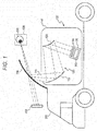
- FIG. 1 is a diagram showing a configuration of a head-up display, in the first exemplary embodiment, equipped in a vehicle.
- Head-up display 100 is equipped in vehicle 200 (an example of a mobile body) which is equipped with windshield 230.
- Head-up display 100 is configured with display unit 120, reflective optical unit 130, and chassis 140.
- Display unit 120 includes illumination device 110 and liquid crystal panel 115.
- Head-up display 100 is a device which projects an image on windshield 230 so that observer 300 can view virtual image 400.
- Illumination device 110 illuminates liquid crystal panel 115, which is a display element.
- Liquid crystal panel 115 displays an image showing, for example, a speedometer or a numerical value indicating a speed.
- Liquid crystal panel 115 functions as a spatial light modulation element and modulates light from illumination device 110 in accordance with a displayed image.
- the modulated light is emitted from liquid crystal panel 115 as transmitted light.
- the transmitted light is introduced into eyebox 600 of observer 300 through reflective optical unit 130 and windshield 230 and is viewed by observer 300 as virtual image 400.
- the observer can view an image of a speedometer or the like as virtual image 400.
- eyebox 600 is an area in which observer 300 can view the entire virtual image.
- Reflective optical unit 130 (an example of an optical element) includes first mirror 131 and second mirror 132.
- First mirror 131 reflects the light emitted from liquid crystal panel 115 toward second mirror 132.
- Second mirror 132 reflects the light from first mirror 131 toward windshield 230.
- a reflection surface of second mirror 132 has a concave shape.
- Reflective optical unit 130 is not necessarily made up of two mirrors, and may be configured with one mirror or three or more mirrors. Further, a refractive optical system such as a lens may be additionally disposed on an optical path of reflective optical unit 130.
- Chassis 140 of head-up display 100 contains display unit 120 and reflective optical unit 130 and has opening 141 through which the light from reflective optical unit 130 is emitted. Opening 141 may be provided with a transparent cover.
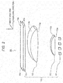
- FIG. 2 is a diagram showing a detailed configuration of display unit 120.
- Display unit 120 includes illumination device 110 and liquid crystal panel 115.
- Liquid crystal panel 115 has incident surface 115a through which light enters, and has emission surface 115b through which light is emitted.
- Incident surface 115a has the same shape as emission surface 115b, which shape is rectangular.
- the X-axis is set in a direction parallel to a longitudinal direction of incident surface 115a and emission surface 115b of liquid crystal panel 115
- the Y-axis is set in a direction parallel to a width direction of incident surface 115a and emission surface 115b
- the Z-axis is set in the normal direction of incident surface 115a and emission surface 115b.
- the X-axis direction (longitudinal direction) is an example of a first direction
- the Y-axis direction (width direction) is an example of a second direction.
- illumination device 110 is configured with a plurality of light source elements 111, first lens 112 disposed in an emitting direction of light source elements 111, second lens 113 disposed in an emitting direction of first lens 112, and diffusion plate 114 (an example of a diffusion member) disposed in an emitting direction of second lens 113.
- Light source elements 111 are, for example, chip light emitting diodes (LEDs) and are light emitting bodies which supply illumination light to liquid crystal panel 115.
- the plurality of light source elements 111 are arranged in a row in the longitudinal direction (the X direction in FIG. 3A ) of liquid crystal panel 115.
- First lens 112 is disposed close to each of light source elements 111 to such an extent that the emitted light from each of light source elements 111 does not leak. First lens 112 takes in the emitted light from each of light source elements 111 from incident surface 112a. Further, first lens 112 has a function to deflect diffused light from light source elements 111 so that the light becomes approximately parallel light in the Y direction, and has a function to emit the light. Further, only one first lens 112 is disposed for the plurality of light source elements 111.
- At least any one of incident surface 112a and emission surface 112b of first lens 112 has a convex shape so that first lens 112 has a positive refractive power.
- the convex shapes of incident surface 112a and emission surface 112b of first lens 112 do not need to be rotationally symmetric about an optical axis, and may have toroidal shapes having different curvatures in the X direction and in the Y direction.
- first lens 112 is a plano-convex lens in which only emission surface 112b has a convex shape.
- Emission surface 112b of first lens 112 has a convex surface in an aspherical surface shape having different curvatures in the X-axis direction and in the Y-axis direction.
- a shape of emission surface 112b in the X-axis direction has a curvature which is smaller (or a curvature radius is larger) in a direction from the center to the edge so that an illuminance distribution on diffusion plate 114 of the emitted light from each of light source elements 111 is uniform.
- a shape of emission surface 112b in the Y-axis direction has a curvature which is smaller on the edge part than on the central part so that the illuminance distribution is uniform on diffusion plate 114.
- Second lens 113 has a function to deflect the emitted light from first lens 112 to an intended direction.
- incident surface 113a of second lens 113 has a convex shape only in the X-axis direction.
- emission surface 113b of second lens 113 has a convex shape which has different curvatures in the X-axis direction and in the Y-axis direction.
- incident surface 113a of second lens 113 may have a convex shape which has different curvatures in the X-axis direction and in the Y-axis direction.
- emission surface 113b of second lens 113 may have a convex shape only in one of the X-axis direction and the Y-axis direction.
- a refractive power of second lens 113 is set depending on an emission angle (or an incident angle of incident light into diffusion plate 114) of emitted light on an edge part of display unit 120.
- second lens 113 does not necessarily need to be provided. If a distance between first lens 112 and diffusion plate 114 is set long, it is possible to achieve an intended emission angle on the edge part of display unit 120 with only first lens 112, without second lens 113.
- First lens 112 and second lens 113 are each made of a transparent material having a predetermined refractive index.
- the refractive index of the transparent material is approximately 1.4 to 1.6, for example.
- resin such as an epoxy resin, a silicone resin, an acrylic resin, and a polycarbonate.
- the polycarbonate is used in consideration of heat resistance properties.
- Diffusion plate 114 diffuses the light deflected by first lens 112 and second lens 113 and emits the diffused light toward liquid crystal panel 115. This arrangement can reduce brightness unevenness of video light which is generated by the plurality of light source elements 111 and which is to be viewed in eyebox 600.
- Diffusion plate 114 only has to be made of optical material having a light diffusing function, and a surface of the plate is made of bead members or is made to have a fine concavo-convex structure or a rough surface, for example. Alternatively, a dotted sheet or a permeable milky white sheet may be used.
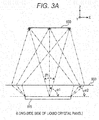
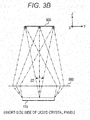
- FIG. 3A and FIG. 3B are diagrams showing optical paths from liquid crystal panel 115 to eyebox 600 in head-up display 100.
- Observer 300 views the transmitted light of liquid crystal panel 115 through virtual image optical system 500.
- Virtual image optical system 500 is a combination of reflective optical unit 130 and windshield 230 shown in FIG. 1 , and is an example of an optical element.
- FIG. 3A shows the optical paths of liquid crystal panel 115 viewed from a long-side side
- FIG. 3B shows the optical paths of liquid crystal panel 115 viewed from a short-side side.
- liquid crystal panel 115 In a case where liquid crystal panel 115 is disposed such that incident surface 115a of liquid crystal panel 115 is parallel to an emission surface of illumination device 110, the emitted light directed from liquid crystal panel 115 toward a center of eyebox 600 is emitted at different emission angles on a central part and on an edge part of liquid crystal panel 115. Specifically, emission angle ⁇ 1 on the central part of liquid crystal panel 115 is larger than emission angle ⁇ 2 on the edge part of liquid crystal panel 115. In concrete, the emitted light on the central part of liquid crystal panel 115 is emitted in a normal direction of emission surface 115b of liquid crystal panel 115, and on the other hand, the emitted light on the edge part is emitted outward of emission surface 115b of the liquid crystal panel.
- liquid crystal panel 115 is not disposed parallel to illumination device 110, this does not apply, and the emitted light on the central part is inclined with respect to the normal direction of emission surface 115b of liquid crystal panel 115. Further, because eyebox 600 is normally longer in the X direction than in the Y direction, the light distribution angle ⁇ 1 (see FIG. 3A ) in the X-axis direction is larger than the light distribution angle ⁇ 2 (see FIG. 3B ) in the Y-axis direction.
- FIG. 4A is a diagram showing optical paths from light source elements 111 to eyebox 600 viewed from the Y-axis direction.
- First lens 112 deflects the emitted light from each of light source elements 111 so that each emitted light from the plurality of light source elements 111 is superposed at a position on diffusion plate 114.
- the refractive power of first lens 112 is set so that each of the plurality of light source elements 111 illuminates the entire surface of liquid crystal panel 115 when viewed from the Y-axis direction.
- the emitted light from light source element 111a and the emitted light from light source element 111c both illuminate the entire area of liquid crystal panel 115.
- Other light source elements 111b and 111d also illuminate in the same way.
- a focal length of first lens 112 is set so that the emitted light from each of light source elements 111a to 111d is applied to the same area of liquid crystal panel 115 in a superposed manner.
- first lens 112 is designed to have the focal length which has the same value as a distance from an optical center of first lens 112 to liquid crystal panel 115.
- the focal length of first lens 112 may be designed to have a value larger than the distance from the optical center of first lens 112 to liquid crystal panel 115.
- Second lens 113 is used to adjust an incident angle of the emitted light from first lens 112 into liquid crystal panel 115.
- second lens 113 deflects the emitted light from first lens 112 in a direction inclined to predetermined angles.
- These predetermined angles are the angles with which it is possible to obtain the emission angles on the central part and the edge part of the liquid crystal panel 115 shown in FIG. 3A and FIG. 3B . That is, the refractive power of second lens 113 is set so that the emission angles are set appropriate to virtual image optical system 500.
- second lens 113 is not essential.
- Diffusion plate 114 has a function to weaken orientation of the light of the plurality of light source elements 111 and to smooth the light distribution characteristics of the emitted light of liquid crystal panel 115.
- the light beam of each of the plurality of light source elements 111 enters diffusion plate 114 at a different angle depending on a position at which the each of light source elements 111 is placed. Therefore, the light can have a larger light distribution angle than diffusion characteristics of diffusion plate 114 in the X-axis direction, with respect to in the Y-axis direction.
- the light distribution angle of the emitted light of liquid crystal panel 115 can be controlled by changing the arrangement of the plurality of light source elements 111. Therefore, in order to increase the light distribution angle, intervals between light source elements 111 may be increased. However, the intervals need to be increased to such an extent that the emitted light of light source elements 111 fully enters first lens 112 without leaking outside.
- FIG. 4C is a diagram showing the optical paths from light source elements 111 to eyebox 600 when viewed from the X-axis direction.
- the emitted light of light source elements 111 enters first lens 112, and second lens 113 deflects the light to such an extent that the light is directed outward.
- virtual image 400 has a long side (a side extends in the longitudinal direction of liquid crystal panel 115) and a short side (a side extends in the width direction of liquid crystal panel 115).
- the refractive powers of first lens 112 and second lens 113 are set so that the light distribution angle of the emitted light of liquid crystal panel 115 is narrower in the Y-axis direction representing the short side direction of illumination device 110 than in the X-axis direction.
- Diffusion plate 114 has a function to diffuse the light entering therein according to the predetermined light distribution characteristics (diffusion angle) and to emit the diffused light.
- the light distribution characteristics are set so that the light having been emitted from diffusion plate 114 and having passed through virtual image optical system 500 finally has broadness corresponding to the width of eyebox 600. Note that, in a case where the light distribution characteristics of diffusion plate 114 are set to achieve the broadness corresponding to the width in the Y-axis direction of eyebox 600, angle characteristics in the X-axis direction cannot be perfectly smoothed in some cases.
- an anisotropic material having diffusibility (diffusion angle) which is different between in the X-axis direction and in the Y-axis direction may be used.
- FIG. 5A is a graph showing the light distribution characteristics of the emitted light on the central part in the X-axis direction, which is the longitudinal direction of liquid crystal panel 115 in the present exemplary embodiment.
- FIG. 5B is a graph showing the light distribution characteristics of the emitted light on the edge part in the X-axis direction, which is the longitudinal direction of liquid crystal panel 115 in the present exemplary embodiment.
- FIG. 5C is a graph showing the light distribution characteristics of the emitted light on the central part in the Y-axis direction, which is the width direction of liquid crystal panel 115 in the present exemplary embodiment.
- the vertical axes of the graphs shown in FIG. 5A to FIG. 5C represent light intensity of liquid crystal panel 115, where a unit is candela.
- the horizontal axes represent the light distribution angle of liquid crystal panel 115, where a unit is degree.
- the drawings show that, on the central part of liquid crystal panel 115, the intensity of the emitted light has a peak in the normal direction of emission surface 115b of liquid crystal panel 115, however, the drawings also show that, on the edge part of liquid crystal panel 115, the intensity of the emitted light has a peak in a direction inclined outward of liquid crystal panel 115 on the basis of the normal direction.
- the light distribution angle in the X-axis direction is larger than the light distribution angle in the Y-axis direction.
- head-up display 100 includes: the plurality of light source elements 111 which are arranged in the X-axis direction (the first direction) and emit light; first lens 112 which takes in from incident surface 112a the light emitted from the plurality of light source elements 111 and emits the light from emission surface 112b; diffusion plate (an example of the diffusion member) 114 disposed on the side of emission surface 112b of first lens 112; liquid crystal panel (an example of the spatial light modulation element) 115 which takes in from incident surface 115a the light having been emitted from the plurality of light source elements 111 and having passed through first lens 112 and diffusion plate 114, modulates the taken-in light in accordance with image information, and emits the modulated light from emission surface 115b; and reflective optical unit 130 which reflects the light emitted from liquid crystal panel 115.
- First lens 112 changes an optical path of light emitted from each of light source elements 111 such that the light emitted from the each of light source
- the emitted light from each of light source elements 111 reaches the same area on the incident surface of liquid crystal panel 115. That is, since the light from each of light source elements 111 illuminates the same area on liquid crystal panel 115, and the illumination is performed without brightness unevenness. Thus, the brightness of virtual image 400 which can be viewed in eyebox 600 is uniform.
- the first exemplary embodiment is described as an example of the technique to be disclosed in the present application.
- the technique in the present disclosure is not limited to the above and can apply to exemplary embodiment in which modification, replacement, addition, and removal are made.
- the components described in the above exemplary embodiment can be combined to make a new exemplary embodiment.
- other exemplary embodiments will be exemplified below.
- liquid crystal panel 115 is used as the spatial light modulation element; however, other display elements can be used as long as the display elements are transmissive displays. Further, in the above description, an example is shown in which liquid crystal panel 115 is disposed perpendicular to principal light beams of light source elements 111; however, liquid crystal panel 115 may be disposed being inclined instead of being perpendicular.
- Fresnel lenses may be used as the emission surfaces and the incident surfaces of first lens 112 and second lens 113. This arrangement can make the lenses thinner. Further, as long as the emitted light from each of the plurality of light source elements 111 is applied to approximately the same area of liquid crystal panel 115 in a superposed manner, the focal length of first lens 112 may be set to a value greater than the distance from the optical center of first lens 112 to emission surface 113b of second lens 113. This arrangement can also generate a virtual image with reduced brightness unevenness.
- one first lens 112 is disposed for the plurality of light source elements 111; however, a plurality of first lenses may be disposed for the plurality of light source elements 111.
- FIG. 6 shows a configuration example of illumination device 110, in which two first lenses 112p and 112q are disposed for the plurality of light source elements 111.
- optical characteristics (focal lengths) of first lenses 112p and 112q are designed so that light from each of light source elements 111 illuminates the entire liquid crystal panel 115.
- a virtual image with small brightness unevenness can be viewed in eyebox 600.
- first lens 112 a convex lens is used; however, a TIR (Total Internal Reflection) lens may be used.
- TIR Total Internal Reflection
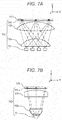
- FIG. 7A and FIG. 7B are diagrams showing a configuration example of illumination device 110 in which TIR lens 112x is used as the first lens.
- FIG. 7A is a diagram showing the configuration example of illumination device 110 when viewed from the Y-axis direction (the width direction of liquid crystal panel 115)
- FIG. 7B is a diagram showing the configuration example of illumination device 110 when viewed from the X-axis direction (the longitudinal direction of liquid crystal panel 115).
- TIR lens 112x is disposed so as to take in leakage light in the Y-axis direction (the width direction of the emitted light of light source elements 111).
- the leakage light of the emitted light of light source elements 111 in the Y-axis direction can be taken in, and the light utilization efficiency can be thus improved.
- light source elements 111 are arranged, in illumination device 110, only in a single row in the Y-axis direction (the width direction of liquid crystal panel 115); however, light source elements 111 may be arranged in a plurality of rows in the Y-axis direction.
- diffusion plate 114 is disposed between second lens 113 and liquid crystal panel 115; however, diffusion plate 114 may be disposed between first lens 112 and second lens 113. This arrangement is less efficient, but even diffusion plate 114 in this position can also reduce the brightness unevenness.
- windshield 230 is exemplified; however, the member is not limited to this, and a combiner may be used.
- LEDs are exemplified; however, laser diodes, organic light-emitting diodes, or the like may be used.
- first lens 112 is described with reference to the example in which each of light source elements 111 illuminates the entire area of liquid crystal panel 115; however, the light from each of light source elements 111 may only be superposed on liquid crystal panel 115 and may not be applied to the entire surface of liquid crystal panel 115.
- a mobile body on which head-up display 100 of the present exemplary embodiment is equipped is not limited to an automotive vehicle but includes a railroad vehicle, a motorbike, an aircraft, a helicopter, a ship, or other various kind of devices which carry people.
- the present disclosure can be applied to a projection device with which a virtual image is viewed. Specifically, the present disclosure can be applied to a head-up display and the like.
Abstract
Description
- The present disclosure relates to a head-up display which displays an image so that an observer can view a virtual image from an eyebox of the observer, and relates to a mobile body equipped with the head-up display.
- PTL 1 discloses a head-up display in which light emitted from a light source in a back of a liquid crystal panel is uniformed to transmission-illuminate the liquid crystal panel. The head-up display includes a light source, a first collective lens, a diffusion plate, and a second collective lens.
- PTL 1: Unexamined Japanese Patent Publication No.
2007-108429 - A head-up display according to a first aspect of the present disclosure includes: a plurality of light source elements which are arranged in a first direction and emit light; a first lens which takes in from an incident surface the light emitted from the plurality of light source elements and emits the light from an emission surface; and a diffusion member disposed on a side of the emission surface of the first lens. The head-up display further includes: a spatial light modulation element which takes in from an incident surface the light having been emitted from the plurality of light source elements and having passed through the first lens and the diffusion member, modulates the taken-in light in accordance with image information, and emits the modulated light from an emission surface, and an optical element which reflects the light emitted from the spatial light modulation element. The first lens changes an optical path of light emitted from each of the light source elements such that the light emitted from the each of the light source elements reaches a same area on the incident surface of the spatial light modulation element.
- In the head-up display in the present disclosure, the first lens causes the light emitted from the plurality of light source elements to illuminate the same area on the incident surface of the spatial light modulation element. With this arrangement, it is possible to display an image with reduced brightness unevenness as a displayed virtual image (image).
-
-
FIG. 1 is a schematic diagram showing a vehicle in which a head-up display in a first exemplary embodiment is equipped. -
FIG. 2 is a diagram for describing a configuration of a display unit of the head-up display in the first exemplary embodiment. -
FIG. 3A is a diagram illustrating optical paths (optical paths viewed from a Y-axis direction) of the head-up display in the first exemplary embodiment. -
FIG. 3B is a diagram illustrating optical paths (optical paths viewed from the X-axis direction) of the head-up display in the first exemplary embodiment. -
FIG. 4A is a diagram showing optical paths in the first exemplary embodiment viewed from the Y-axis direction. -
FIG. 4B is a diagram for illustrating optical paths (optical paths viewed from the X-axis direction) of the light source elements. -
FIG. 4C is a diagram showing optical paths in the first exemplary embodiment viewed from the X-axis direction. -
FIG. 5A is a graph showing a distribution (on a central part in the X-axis direction) of emitted light of the display unit (liquid crystal panel) in the first exemplary embodiment. -
FIG. 5B is a graph showing a distribution (on an edge part in the X-axis direction) of the emitted light of the display unit (liquid crystal panel) in the first exemplary embodiment. -
FIG. 5C is a graph showing a distribution (on a central part of the Y-axis direction) of the emitted light of the display unit (liquid crystal panel) in the first exemplary embodiment. -
FIG. 6 is a diagram showing an example of another configuration of the display unit. -
FIG. 7A is a diagram showing a configuration (a configuration viewed from the Y-axis direction) of an illumination device using a TIR lens. -
FIG. 7B is a diagram showing a configuration (a configuration viewed from the X-axis direction) of the illumination device using a TIR lens. - In the following, an exemplary embodiment will be described in detail, appropriately with reference to the drawings. However, the exemplary embodiments will not be described in detail in some cases. For example, a detailed description of a well-known matter and a duplicated description of substantially the same configuration will be omitted in some cases. This is to avoid the following description from being unnecessarily redundant and thus to help those skilled in the art to easily understand the description. Note that the accompanying drawings and the following description are provided to help those skilled in the art to sufficiently understand the present disclosure, but are not intended to limit the subject matters of the claims.
- In the following, a first exemplary embodiment will be described with reference to the accompanying drawings.
-
FIG. 1 is a diagram showing a configuration of a head-up display, in the first exemplary embodiment, equipped in a vehicle. Head-updisplay 100 is equipped in vehicle 200 (an example of a mobile body) which is equipped withwindshield 230. Head-updisplay 100 is configured withdisplay unit 120, reflectiveoptical unit 130, andchassis 140.Display unit 120 includesillumination device 110 andliquid crystal panel 115. - Head-up
display 100 is a device which projects an image onwindshield 230 so thatobserver 300 can viewvirtual image 400. -
Illumination device 110 illuminatesliquid crystal panel 115, which is a display element.Liquid crystal panel 115 displays an image showing, for example, a speedometer or a numerical value indicating a speed.Liquid crystal panel 115 functions as a spatial light modulation element and modulates light fromillumination device 110 in accordance with a displayed image. The modulated light is emitted fromliquid crystal panel 115 as transmitted light. The transmitted light is introduced intoeyebox 600 ofobserver 300 through reflectiveoptical unit 130 andwindshield 230 and is viewed byobserver 300 asvirtual image 400. For example, the observer can view an image of a speedometer or the like asvirtual image 400. Here,eyebox 600 is an area in whichobserver 300 can view the entire virtual image. - Reflective optical unit 130 (an example of an optical element) includes
first mirror 131 andsecond mirror 132.First mirror 131 reflects the light emitted fromliquid crystal panel 115 towardsecond mirror 132.Second mirror 132 reflects the light fromfirst mirror 131 towardwindshield 230. A reflection surface ofsecond mirror 132 has a concave shape. Reflectiveoptical unit 130 is not necessarily made up of two mirrors, and may be configured with one mirror or three or more mirrors. Further, a refractive optical system such as a lens may be additionally disposed on an optical path of reflectiveoptical unit 130. -
Chassis 140 of head-updisplay 100 containsdisplay unit 120 and reflectiveoptical unit 130 and has opening 141 through which the light from reflectiveoptical unit 130 is emitted. Opening 141 may be provided with a transparent cover. -
FIG. 2 is a diagram showing a detailed configuration ofdisplay unit 120.Display unit 120 includesillumination device 110 andliquid crystal panel 115.Liquid crystal panel 115 hasincident surface 115a through which light enters, and hasemission surface 115b through which light is emitted.Incident surface 115a has the same shape asemission surface 115b, which shape is rectangular. - Note that, in the following description, three-dimensional orthogonal coordinate systems are set in the drawings. Specifically, the X-axis is set in a direction parallel to a longitudinal direction of
incident surface 115a andemission surface 115b ofliquid crystal panel 115, the Y-axis is set in a direction parallel to a width direction ofincident surface 115a andemission surface 115b, and the Z-axis is set in the normal direction ofincident surface 115a andemission surface 115b. Note that the X-axis direction (longitudinal direction) is an example of a first direction, the Y-axis direction (width direction) is an example of a second direction. - As shown in
FIG. 2 ,illumination device 110 is configured with a plurality oflight source elements 111,first lens 112 disposed in an emitting direction oflight source elements 111,second lens 113 disposed in an emitting direction offirst lens 112, and diffusion plate 114 (an example of a diffusion member) disposed in an emitting direction ofsecond lens 113. -
Light source elements 111 are, for example, chip light emitting diodes (LEDs) and are light emitting bodies which supply illumination light toliquid crystal panel 115. The plurality oflight source elements 111 are arranged in a row in the longitudinal direction (the X direction inFIG. 3A ) ofliquid crystal panel 115. -
First lens 112 is disposed close to each oflight source elements 111 to such an extent that the emitted light from each oflight source elements 111 does not leak.First lens 112 takes in the emitted light from each oflight source elements 111 fromincident surface 112a. Further,first lens 112 has a function to deflect diffused light fromlight source elements 111 so that the light becomes approximately parallel light in the Y direction, and has a function to emit the light. Further, only onefirst lens 112 is disposed for the plurality oflight source elements 111. - At least any one of
incident surface 112a andemission surface 112b offirst lens 112 has a convex shape so thatfirst lens 112 has a positive refractive power. Note that the convex shapes ofincident surface 112a andemission surface 112b offirst lens 112 do not need to be rotationally symmetric about an optical axis, and may have toroidal shapes having different curvatures in the X direction and in the Y direction. In the present exemplary embodiment,first lens 112 is a plano-convex lens in which onlyemission surface 112b has a convex shape. -
Emission surface 112b offirst lens 112 has a convex surface in an aspherical surface shape having different curvatures in the X-axis direction and in the Y-axis direction. A shape ofemission surface 112b in the X-axis direction has a curvature which is smaller (or a curvature radius is larger) in a direction from the center to the edge so that an illuminance distribution ondiffusion plate 114 of the emitted light from each oflight source elements 111 is uniform. Further, a shape ofemission surface 112b in the Y-axis direction has a curvature which is smaller on the edge part than on the central part so that the illuminance distribution is uniform ondiffusion plate 114. -
Second lens 113 has a function to deflect the emitted light fromfirst lens 112 to an intended direction. In the present exemplary embodiment,incident surface 113a ofsecond lens 113 has a convex shape only in the X-axis direction. Further,emission surface 113b ofsecond lens 113 has a convex shape which has different curvatures in the X-axis direction and in the Y-axis direction. However,incident surface 113a ofsecond lens 113 may have a convex shape which has different curvatures in the X-axis direction and in the Y-axis direction. Further,emission surface 113b ofsecond lens 113 may have a convex shape only in one of the X-axis direction and the Y-axis direction. A refractive power ofsecond lens 113 is set depending on an emission angle (or an incident angle of incident light into diffusion plate 114) of emitted light on an edge part ofdisplay unit 120. However,second lens 113 does not necessarily need to be provided. If a distance betweenfirst lens 112 anddiffusion plate 114 is set long, it is possible to achieve an intended emission angle on the edge part ofdisplay unit 120 with onlyfirst lens 112, withoutsecond lens 113. -
First lens 112 andsecond lens 113 are each made of a transparent material having a predetermined refractive index. The refractive index of the transparent material is approximately 1.4 to 1.6, for example. As such a transparent material, it is possible to use resin such as an epoxy resin, a silicone resin, an acrylic resin, and a polycarbonate. In the present exemplary embodiment, the polycarbonate is used in consideration of heat resistance properties. -
Diffusion plate 114 diffuses the light deflected byfirst lens 112 andsecond lens 113 and emits the diffused light towardliquid crystal panel 115. This arrangement can reduce brightness unevenness of video light which is generated by the plurality oflight source elements 111 and which is to be viewed ineyebox 600.Diffusion plate 114 only has to be made of optical material having a light diffusing function, and a surface of the plate is made of bead members or is made to have a fine concavo-convex structure or a rough surface, for example. Alternatively, a dotted sheet or a permeable milky white sheet may be used. - In the following, a description will be given on an optical path of light emitted from
light source elements 111 in head-updisplay 100 of the present exemplary embodiment. -
FIG. 3A andFIG. 3B are diagrams showing optical paths fromliquid crystal panel 115 toeyebox 600 in head-updisplay 100.Observer 300 views the transmitted light ofliquid crystal panel 115 through virtual imageoptical system 500. Virtual imageoptical system 500 is a combination of reflectiveoptical unit 130 andwindshield 230 shown inFIG. 1 , and is an example of an optical element.FIG. 3A shows the optical paths ofliquid crystal panel 115 viewed from a long-side side, andFIG. 3B shows the optical paths ofliquid crystal panel 115 viewed from a short-side side. - In a case where
liquid crystal panel 115 is disposed such thatincident surface 115a ofliquid crystal panel 115 is parallel to an emission surface ofillumination device 110, the emitted light directed fromliquid crystal panel 115 toward a center ofeyebox 600 is emitted at different emission angles on a central part and on an edge part ofliquid crystal panel 115. Specifically, emission angle α1 on the central part ofliquid crystal panel 115 is larger than emission angle α2 on the edge part ofliquid crystal panel 115. In concrete, the emitted light on the central part ofliquid crystal panel 115 is emitted in a normal direction ofemission surface 115b ofliquid crystal panel 115, and on the other hand, the emitted light on the edge part is emitted outward ofemission surface 115b of the liquid crystal panel. In a case whereliquid crystal panel 115 is not disposed parallel toillumination device 110, this does not apply, and the emitted light on the central part is inclined with respect to the normal direction ofemission surface 115b ofliquid crystal panel 115. Further, becauseeyebox 600 is normally longer in the X direction than in the Y direction, the light distribution angle β1 (seeFIG. 3A ) in the X-axis direction is larger than the light distribution angle β2 (seeFIG. 3B ) in the Y-axis direction. -
FIG. 4A is a diagram showing optical paths fromlight source elements 111 to eyebox 600 viewed from the Y-axis direction.First lens 112 deflects the emitted light from each oflight source elements 111 so that each emitted light from the plurality oflight source elements 111 is superposed at a position ondiffusion plate 114. - That is, the refractive power of
first lens 112 is set so that each of the plurality oflight source elements 111 illuminates the entire surface ofliquid crystal panel 115 when viewed from the Y-axis direction. For example, as shown inFIG. 4B , the emitted light fromlight source element 111a and the emitted light fromlight source element 111c both illuminate the entire area ofliquid crystal panel 115. Otherlight source elements - In this manner, a light beam from each of the plurality of
light source elements 111 is applied to the entire liquid crystal panel 115 (the same area) in a superposed manner. Thus, the brightness ofvirtual image 400 which can be viewed ineyebox 600 is uniform. - A focal length of
first lens 112 is set so that the emitted light from each oflight source elements 111a to 111d is applied to the same area ofliquid crystal panel 115 in a superposed manner. Specifically,first lens 112 is designed to have the focal length which has the same value as a distance from an optical center offirst lens 112 toliquid crystal panel 115. - Note that, if the emitted light from each of the plurality of
light source elements 111 can be applied to approximately the same area ofliquid crystal panel 115 in a superposed manner, the focal length offirst lens 112 may be designed to have a value larger than the distance from the optical center offirst lens 112 toliquid crystal panel 115. -
Second lens 113 is used to adjust an incident angle of the emitted light fromfirst lens 112 intoliquid crystal panel 115. In other words,second lens 113 deflects the emitted light fromfirst lens 112 in a direction inclined to predetermined angles. These predetermined angles are the angles with which it is possible to obtain the emission angles on the central part and the edge part of theliquid crystal panel 115 shown inFIG. 3A andFIG. 3B . That is, the refractive power ofsecond lens 113 is set so that the emission angles are set appropriate to virtual imageoptical system 500. As described above,second lens 113 is not essential. -
Diffusion plate 114 has a function to weaken orientation of the light of the plurality oflight source elements 111 and to smooth the light distribution characteristics of the emitted light ofliquid crystal panel 115. The light beam of each of the plurality oflight source elements 111 entersdiffusion plate 114 at a different angle depending on a position at which the each oflight source elements 111 is placed. Therefore, the light can have a larger light distribution angle than diffusion characteristics ofdiffusion plate 114 in the X-axis direction, with respect to in the Y-axis direction. Note that the light distribution angle of the emitted light ofliquid crystal panel 115 can be controlled by changing the arrangement of the plurality oflight source elements 111. Therefore, in order to increase the light distribution angle, intervals betweenlight source elements 111 may be increased. However, the intervals need to be increased to such an extent that the emitted light oflight source elements 111 fully entersfirst lens 112 without leaking outside. -
FIG. 4C is a diagram showing the optical paths fromlight source elements 111 toeyebox 600 when viewed from the X-axis direction. The emitted light oflight source elements 111 entersfirst lens 112, andsecond lens 113 deflects the light to such an extent that the light is directed outward. In the present exemplary embodiment,virtual image 400 has a long side (a side extends in the longitudinal direction of liquid crystal panel 115) and a short side (a side extends in the width direction of liquid crystal panel 115). The refractive powers offirst lens 112 andsecond lens 113 are set so that the light distribution angle of the emitted light ofliquid crystal panel 115 is narrower in the Y-axis direction representing the short side direction ofillumination device 110 than in the X-axis direction. -
Diffusion plate 114 has a function to diffuse the light entering therein according to the predetermined light distribution characteristics (diffusion angle) and to emit the diffused light. The light distribution characteristics are set so that the light having been emitted fromdiffusion plate 114 and having passed through virtual imageoptical system 500 finally has broadness corresponding to the width ofeyebox 600. Note that, in a case where the light distribution characteristics ofdiffusion plate 114 are set to achieve the broadness corresponding to the width in the Y-axis direction ofeyebox 600, angle characteristics in the X-axis direction cannot be perfectly smoothed in some cases. In that case, as a material ofdiffusion plate 114, an anisotropic material having diffusibility (diffusion angle) which is different between in the X-axis direction and in the Y-axis direction may be used. Alternatively, it is also possible to adjust intervals at which the plurality oflight source elements 111 are arranged. -
FIG. 5A is a graph showing the light distribution characteristics of the emitted light on the central part in the X-axis direction, which is the longitudinal direction ofliquid crystal panel 115 in the present exemplary embodiment.FIG. 5B is a graph showing the light distribution characteristics of the emitted light on the edge part in the X-axis direction, which is the longitudinal direction ofliquid crystal panel 115 in the present exemplary embodiment.FIG. 5C is a graph showing the light distribution characteristics of the emitted light on the central part in the Y-axis direction, which is the width direction ofliquid crystal panel 115 in the present exemplary embodiment. The vertical axes of the graphs shown inFIG. 5A to FIG. 5C represent light intensity ofliquid crystal panel 115, where a unit is candela. The horizontal axes represent the light distribution angle ofliquid crystal panel 115, where a unit is degree. - With reference to
FIG. 5A and FIG. 5B , the drawings show that, on the central part ofliquid crystal panel 115, the intensity of the emitted light has a peak in the normal direction ofemission surface 115b ofliquid crystal panel 115, however, the drawings also show that, on the edge part ofliquid crystal panel 115, the intensity of the emitted light has a peak in a direction inclined outward ofliquid crystal panel 115 on the basis of the normal direction. Further, as shown inFIG. 5A and FIG. 5C , inliquid crystal panel 115 of the present exemplary embodiment, the light distribution angle in the X-axis direction is larger than the light distribution angle in the Y-axis direction. This arrangement makes it possible that, in head-updisplay 100 which displaysvirtual image 400 larger than the area ofliquid crystal panel 115, virtual image having a uniform brightness distribution is viewed ineyebox 600. - As described above, in the present exemplary embodiment, head-up
display 100 includes: the plurality oflight source elements 111 which are arranged in the X-axis direction (the first direction) and emit light;first lens 112 which takes in fromincident surface 112a the light emitted from the plurality oflight source elements 111 and emits the light fromemission surface 112b; diffusion plate (an example of the diffusion member) 114 disposed on the side ofemission surface 112b offirst lens 112; liquid crystal panel (an example of the spatial light modulation element) 115 which takes in fromincident surface 115a the light having been emitted from the plurality oflight source elements 111 and having passed throughfirst lens 112 anddiffusion plate 114, modulates the taken-in light in accordance with image information, and emits the modulated light fromemission surface 115b; and reflectiveoptical unit 130 which reflects the light emitted fromliquid crystal panel 115.First lens 112 changes an optical path of light emitted from each oflight source elements 111 such that the light emitted from the each oflight source elements 111 reaches the same area onincident surface 115a ofliquid crystal panel 115. - With this configuration, the emitted light from each of
light source elements 111 reaches the same area on the incident surface ofliquid crystal panel 115. That is, since the light from each oflight source elements 111 illuminates the same area onliquid crystal panel 115, and the illumination is performed without brightness unevenness. Thus, the brightness ofvirtual image 400 which can be viewed ineyebox 600 is uniform. - In the above, the first exemplary embodiment is described as an example of the technique to be disclosed in the present application. However, the technique in the present disclosure is not limited to the above and can apply to exemplary embodiment in which modification, replacement, addition, and removal are made. Further, the components described in the above exemplary embodiment can be combined to make a new exemplary embodiment. Thus, other exemplary embodiments will be exemplified below.
- In the above exemplary embodiment,
liquid crystal panel 115 is used as the spatial light modulation element; however, other display elements can be used as long as the display elements are transmissive displays. Further, in the above description, an example is shown in whichliquid crystal panel 115 is disposed perpendicular to principal light beams oflight source elements 111; however,liquid crystal panel 115 may be disposed being inclined instead of being perpendicular. - As the emission surfaces and the incident surfaces of
first lens 112 andsecond lens 113, Fresnel lenses may be used. This arrangement can make the lenses thinner. Further, as long as the emitted light from each of the plurality oflight source elements 111 is applied to approximately the same area ofliquid crystal panel 115 in a superposed manner, the focal length offirst lens 112 may be set to a value greater than the distance from the optical center offirst lens 112 toemission surface 113b ofsecond lens 113. This arrangement can also generate a virtual image with reduced brightness unevenness. - In the above exemplary embodiment, one
first lens 112 is disposed for the plurality oflight source elements 111; however, a plurality of first lenses may be disposed for the plurality oflight source elements 111.FIG. 6 shows a configuration example ofillumination device 110, in which twofirst lenses light source elements 111. In this case, optical characteristics (focal lengths) offirst lenses light source elements 111 illuminates the entireliquid crystal panel 115. Also with this configuration, a virtual image with small brightness unevenness can be viewed ineyebox 600. - As
first lens 112, a convex lens is used; however, a TIR (Total Internal Reflection) lens may be used. With this arrangement, the light fromlight source elements 111 can be efficiently emitted tosecond lens 113, and light utilization efficiency can be improved. -
FIG. 7A and FIG. 7B are diagrams showing a configuration example ofillumination device 110 in whichTIR lens 112x is used as the first lens.FIG. 7A is a diagram showing the configuration example ofillumination device 110 when viewed from the Y-axis direction (the width direction of liquid crystal panel 115), andFIG. 7B is a diagram showing the configuration example ofillumination device 110 when viewed from the X-axis direction (the longitudinal direction of liquid crystal panel 115). - As shown in
FIG. 7B , in the present exemplary embodiment,TIR lens 112x is disposed so as to take in leakage light in the Y-axis direction (the width direction of the emitted light of light source elements 111). With this arrangement, the leakage light of the emitted light oflight source elements 111 in the Y-axis direction can be taken in, and the light utilization efficiency can be thus improved. - In the above exemplary embodiment,
light source elements 111 are arranged, inillumination device 110, only in a single row in the Y-axis direction (the width direction of liquid crystal panel 115); however,light source elements 111 may be arranged in a plurality of rows in the Y-axis direction. In the above exemplary embodiment,diffusion plate 114 is disposed betweensecond lens 113 andliquid crystal panel 115; however,diffusion plate 114 may be disposed betweenfirst lens 112 andsecond lens 113. This arrangement is less efficient, but evendiffusion plate 114 in this position can also reduce the brightness unevenness. - As a member for reflecting the emitted light of head-up
display 100,windshield 230 is exemplified; however, the member is not limited to this, and a combiner may be used. - As the light source, LEDs are exemplified; however, laser diodes, organic light-emitting diodes, or the like may be used.
- In the above exemplary embodiment,
first lens 112 is described with reference to the example in which each oflight source elements 111 illuminates the entire area ofliquid crystal panel 115; however, the light from each oflight source elements 111 may only be superposed onliquid crystal panel 115 and may not be applied to the entire surface ofliquid crystal panel 115. - A mobile body on which head-up
display 100 of the present exemplary embodiment is equipped is not limited to an automotive vehicle but includes a railroad vehicle, a motorbike, an aircraft, a helicopter, a ship, or other various kind of devices which carry people. - The present disclosure can be applied to a projection device with which a virtual image is viewed. Specifically, the present disclosure can be applied to a head-up display and the like.
-
- 100
- head-up display
- 110
- illumination device
- 111, 111b, 111c, 111d
- light source element
- 112, 112p, 112q
- first lens
- 112a
- incident surface
- 112b
- emission surface
- 112x
- TIR lens
- 113
- second lens
- 113a
- incident surface
- 113b
- emission surface
- 114
- diffusion plate (diffusion member)
- 115
- liquid crystal panel (spatial light modulation element)
- 115a
- incident surface
- 115b
- emission surface
- 120
- display unit
- 130
- reflective optical unit
- 131
- first mirror
- 132
- second mirror
- 140
- chassis
- 141
- opening
- 200
- vehicle
- 230
- windshield
- 300
- observer
- 400
- virtual image
- 500
- virtual image optical system (optical element)
- 600
- eyebox
Claims (9)
- A head-up display comprising:a plurality of light source elements which are arranged in a first direction and emit light;a first lens which receives through an incident surface the light emitted from the plurality of light source elements and emits the light from an emission surface;a diffusion member disposed on an emission surface side of the first lens;a spatial light modulation element which takes in from an incident surface the light having been emitted from the plurality of light source elements and having passed through the first lens and the diffusion member, modulates the taken-in light in accordance with image information, and emits the modulated light from an emission surface; andan optical element which reflects the light emitted from the spatial light modulation element,wherein the first lens changes an optical path of the light emitted from each of the light source elements such that the light emitted from the each of the light source elements reaches a same area on the incident surface of the spatial light modulation element.
- The head-up display according to claim 1, wherein a focal length of the first lens is set to a value equal to or greater than a distance from an optical center of the first lens to the spatial light modulation element.
- The head-up display according to claim 1, wherein a curvature, in the first direction, of the emission surface of the first lens is smaller on an edge part of the emission surface of the first lens than on a central part of the emission surface of the first lens.
- The head-up display according to claim 1, wherein a curvature of the emission surface of the first lens is different between in the first direction and in a second direction perpendicular to the first direction.
- The head-up display according to claim 1, wherein a curvature, of the emission surface of the first lens, in a second direction perpendicular to the first direction is smaller on an edge part of the emission surface of the first lens than on a central part of the emission surface of the first lens.
- The head-up display according to claim 1, further comprising a second lens which is disposed on the emission surface side of the first lens and has an incident surface and an emission surface,
wherein at least one of the incident surface and the emission surface is a convex surface. - The head-up display according to claim 6, wherein a curvature of the emission surface of the second lens is different between in the first direction and a second direction perpendicular to the first direction.
- The head-up display according to claim 1, wherein the head-up display is equipped in a mobile body having a windshield.
- A mobile body comprising a head-up display, the head-up display including:a plurality of light source elements which are arranged in a first direction and emit light;a first lens which receives through an incident surface the light emitted from the plurality of light source elements and emits the light from an emission surface;a diffusion member disposed on an emission surface side of the first lens;a spatial light modulation element which takes in from an incident surface the light having been emitted from the plurality of light source elements and having passed through the first lens and the diffusion member, modulates the taken-in light in accordance with image information, and emits the modulated light from an emission surface; andan optical element which reflects the light emitted from the spatial light modulation element,wherein the first lens changes an optical path of the light emitted from each of the light source elements such that the light emitted from the each of the light source elements reaches a same area on the incident surface of the spatial light modulation element.
Applications Claiming Priority (2)
| Application Number | Priority Date | Filing Date | Title |
|---|---|---|---|
| JP2014263761 | 2014-12-26 | ||
| PCT/JP2015/005491 WO2016103549A1 (en) | 2014-12-26 | 2015-11-02 | Headup display and mobile body provided with headup display |
Publications (3)
| Publication Number | Publication Date |
|---|---|
| EP3076223A1 true EP3076223A1 (en) | 2016-10-05 |
| EP3076223A4 EP3076223A4 (en) | 2017-03-29 |
| EP3076223B1 EP3076223B1 (en) | 2019-01-09 |
Family
ID=55347063
Family Applications (1)
| Application Number | Title | Priority Date | Filing Date |
|---|---|---|---|
| EP15871297.6A Active EP3076223B1 (en) | 2014-12-26 | 2015-11-02 | Headup display and mobile body provided with headup display |
Country Status (4)
| Country | Link |
|---|---|
| US (1) | US10025095B2 (en) |
| EP (1) | EP3076223B1 (en) |
| JP (1) | JP5866644B1 (en) |
| WO (1) | WO2016103549A1 (en) |
Cited By (3)
| Publication number | Priority date | Publication date | Assignee | Title |
|---|---|---|---|---|
| CN107850780A (en) * | 2015-06-29 | 2018-03-27 | 微软技术许可有限责任公司 | Holographic nearly eye is shown |
| CN110234004A (en) * | 2018-03-06 | 2019-09-13 | 夏普株式会社 | Display device, display methods and recording medium |
| EP3543771A1 (en) * | 2018-03-20 | 2019-09-25 | Panasonic Intellectual Property Management Co., Ltd. | Head-up display and moving object |
Families Citing this family (22)
| Publication number | Priority date | Publication date | Assignee | Title |
|---|---|---|---|---|
| JP6319354B2 (en) * | 2016-02-23 | 2018-05-09 | 株式会社デンソー | Head-up display device |
| WO2017145558A1 (en) * | 2016-02-23 | 2017-08-31 | 株式会社デンソー | Head-up display device |
| JP6481649B2 (en) * | 2016-03-29 | 2019-03-13 | 株式会社デンソー | Head-up display device |
| JP6409015B2 (en) * | 2016-03-29 | 2018-10-17 | 矢崎総業株式会社 | Projection display device for vehicle |
| JP6451686B2 (en) * | 2016-04-26 | 2019-01-16 | 株式会社デンソー | Head-up display device |
| JP6508125B2 (en) * | 2016-05-18 | 2019-05-08 | 株式会社デンソー | HEAD-UP DISPLAY DEVICE AND IMAGE PROJECTION UNIT |
| FR3053805A1 (en) * | 2016-07-05 | 2018-01-12 | Valeo Comfort And Driving Assistance | IMAGE GENERATING DEVICE FOR HEAD-UP DISPLAY AND METHOD FOR CONTROLLING SUCH A DEVICE |
| KR101837414B1 (en) * | 2016-11-14 | 2018-03-12 | 에이치엘비 주식회사 | Back light unit module of head-up-display apparatus |
| JP2018163259A (en) * | 2017-03-24 | 2018-10-18 | パナソニックIpマネジメント株式会社 | Image display device, virtual image display device, and movable body |
| JP6982816B2 (en) * | 2017-03-24 | 2021-12-17 | パナソニックIpマネジメント株式会社 | Image display device, virtual image display device, moving object |
| JP6717273B2 (en) | 2017-08-07 | 2020-07-01 | 株式会社デンソー | Head up display device |
| CN107577046B (en) * | 2017-08-22 | 2019-11-26 | 苏州车萝卜汽车电子科技有限公司 | A kind of HUD lighting system, head-up display device and implementation method |
| US10337882B2 (en) * | 2017-11-02 | 2019-07-02 | Opticser Co., Ltd. | Optical projection system and devices thereof |
| DE102018207516B3 (en) * | 2018-05-15 | 2019-11-14 | Continental Automotive Gmbh | Head-up display with one of several distributed light sources illuminated display |
| US10427602B1 (en) * | 2018-06-21 | 2019-10-01 | Gm Global Technology Operations Llc. | Optical system for enhancing display viewing comfort |
| JP7122673B2 (en) | 2018-06-29 | 2022-08-22 | パナソニックIpマネジメント株式会社 | display, display system, moving object |
| EP3663813A1 (en) * | 2018-12-03 | 2020-06-10 | Valeo Comfort and Driving Assistance | Device for the generation of images and associated head-up display |
| JP7253717B2 (en) | 2019-05-30 | 2023-04-07 | パナソニックIpマネジメント株式会社 | Projection device and head-up display |
| WO2021195359A1 (en) * | 2020-03-25 | 2021-09-30 | Continental Automotive Systems, Inc. | Elliptical hud eye box illumination |
| WO2021246001A1 (en) * | 2020-06-04 | 2021-12-09 | パナソニックIpマネジメント株式会社 | Display device, head-up display, and mobile object |
| JP7244556B2 (en) * | 2021-02-24 | 2023-03-22 | マクセル株式会社 | Light source device and head-up display device |
| JP2023118016A (en) * | 2022-02-14 | 2023-08-24 | 株式会社小糸製作所 | Optical member, light source device, and head-up display |
Citations (3)
| Publication number | Priority date | Publication date | Assignee | Title |
|---|---|---|---|---|
| JP2006310367A (en) * | 2005-04-26 | 2006-11-09 | Nippon Seiki Co Ltd | Lighting device, and liquid crystal display with same |
| US20070024977A1 (en) * | 2005-07-27 | 2007-02-01 | Atsushi Kawamura | Light source apparatus, optical modulation apparatus, display apparatus, light condense illumination apparatus and projection type color display apparatus |
| JP2012203176A (en) * | 2011-03-25 | 2012-10-22 | Nippon Seiki Co Ltd | Head-up display device |
Family Cites Families (25)
| Publication number | Priority date | Publication date | Assignee | Title |
|---|---|---|---|---|
| JP2696360B2 (en) * | 1988-10-28 | 1998-01-14 | 旭光学工業株式会社 | Illumination optics |
| JP3960377B2 (en) * | 2002-07-19 | 2007-08-15 | Necディスプレイソリューションズ株式会社 | Light source device and projection display device |
| JP2007108429A (en) * | 2005-10-13 | 2007-04-26 | Denso Corp | Display device and headup display device for vehicle equipped therewith |
| US8491121B2 (en) * | 2007-10-09 | 2013-07-23 | Elbit Systems Of America, Llc | Pupil scan apparatus |
| ES2368463T3 (en) * | 2008-02-19 | 2011-11-17 | Saab Ab | FRONT DISPLAY SCREEN WITH BRIGHTNESS CONTROL. |
| JP4623161B2 (en) * | 2008-08-07 | 2011-02-02 | 株式会社デンソー | Liquid crystal display device |
| JP5126051B2 (en) * | 2008-12-25 | 2013-01-23 | 株式会社デンソー | Lighting device |
| WO2011015843A2 (en) * | 2009-08-07 | 2011-02-10 | Light Blue Optics Ltd | Head up displays |
| JP2011090217A (en) * | 2009-10-23 | 2011-05-06 | Denso Corp | Lighting device |
| CN102155713B (en) * | 2010-04-08 | 2013-06-05 | 深圳市光峰光电技术有限公司 | Light mixing luminaire |
| US8436952B2 (en) * | 2010-05-28 | 2013-05-07 | Hong Kong Applied Science and Technology Research Institute Company Limited | Hybrid illumination system for head-up display |
| US9285588B2 (en) * | 2010-10-01 | 2016-03-15 | Panasonic Intellectual Property Management Co., Ltd. | See-through display device and vehicle having see-through display device mounted thereon |
| JP5223941B2 (en) | 2011-03-28 | 2013-06-26 | カシオ計算機株式会社 | Projection device |
| DE102011076083A1 (en) * | 2011-05-18 | 2012-11-22 | Fraunhofer-Gesellschaft zur Förderung der angewandten Forschung e.V. | Projection display and method for displaying an overall image for projection relief surfaces or tilted projection surfaces |
| JP6027727B2 (en) * | 2011-09-09 | 2016-11-16 | 矢崎総業株式会社 | Vehicle display device |
| CN102402005B (en) * | 2011-12-06 | 2015-11-25 | 北京理工大学 | Bifocal-surface monocular stereo helmet-mounted display device with free-form surfaces |
| JP5910324B2 (en) | 2012-06-04 | 2016-04-27 | ソニー株式会社 | Illumination device, projection display device, and direct view display device |
| US20150262424A1 (en) * | 2013-01-31 | 2015-09-17 | Google Inc. | Depth and Focus Discrimination for a Head-mountable device using a Light-Field Display System |
| JP6036437B2 (en) * | 2013-03-20 | 2016-11-30 | 日本精機株式会社 | Head-up display device |
| FR3003521B1 (en) * | 2013-03-21 | 2016-10-07 | Valeo Vision | LIGHTING AND / OR SIGNALING MODULE FOR MOTOR VEHICLE |
| JP6489711B2 (en) * | 2013-06-03 | 2019-03-27 | コーニンクレッカ フィリップス エヌ ヴェKoninklijke Philips N.V. | Multi-view display device |
| EP3017335B1 (en) * | 2013-07-02 | 2019-02-27 | Koninklijke Philips N.V. | Auto-stereoscopic display device with a striped backlight and two lenticular lens arrays |
| US9291819B2 (en) * | 2013-09-05 | 2016-03-22 | Texas Instruments Incorporated | Multi-focus heads-up display using single picture generator unit |
| JP2015084079A (en) * | 2013-09-20 | 2015-04-30 | パナソニックIpマネジメント株式会社 | Image display device |
| JPWO2015045251A1 (en) * | 2013-09-27 | 2017-03-09 | パナソニックIpマネジメント株式会社 | Autostereoscopic image device |
-
2015
- 2015-05-29 JP JP2015110474A patent/JP5866644B1/en active Active
- 2015-11-02 EP EP15871297.6A patent/EP3076223B1/en active Active
- 2015-11-02 WO PCT/JP2015/005491 patent/WO2016103549A1/en active Application Filing
-
2016
- 2016-06-21 US US15/188,648 patent/US10025095B2/en active Active
Patent Citations (3)
| Publication number | Priority date | Publication date | Assignee | Title |
|---|---|---|---|---|
| JP2006310367A (en) * | 2005-04-26 | 2006-11-09 | Nippon Seiki Co Ltd | Lighting device, and liquid crystal display with same |
| US20070024977A1 (en) * | 2005-07-27 | 2007-02-01 | Atsushi Kawamura | Light source apparatus, optical modulation apparatus, display apparatus, light condense illumination apparatus and projection type color display apparatus |
| JP2012203176A (en) * | 2011-03-25 | 2012-10-22 | Nippon Seiki Co Ltd | Head-up display device |
Non-Patent Citations (1)
| Title |
|---|
| See also references of WO2016103549A1 * |
Cited By (4)
| Publication number | Priority date | Publication date | Assignee | Title |
|---|---|---|---|---|
| CN107850780A (en) * | 2015-06-29 | 2018-03-27 | 微软技术许可有限责任公司 | Holographic nearly eye is shown |
| CN107850780B (en) * | 2015-06-29 | 2020-08-21 | 微软技术许可有限责任公司 | Holographic near-to-eye display |
| CN110234004A (en) * | 2018-03-06 | 2019-09-13 | 夏普株式会社 | Display device, display methods and recording medium |
| EP3543771A1 (en) * | 2018-03-20 | 2019-09-25 | Panasonic Intellectual Property Management Co., Ltd. | Head-up display and moving object |
Also Published As
| Publication number | Publication date |
|---|---|
| US10025095B2 (en) | 2018-07-17 |
| US20160299342A1 (en) | 2016-10-13 |
| EP3076223B1 (en) | 2019-01-09 |
| JP2016126314A (en) | 2016-07-11 |
| EP3076223A4 (en) | 2017-03-29 |
| JP5866644B1 (en) | 2016-02-17 |
| WO2016103549A1 (en) | 2016-06-30 |
Similar Documents
| Publication | Publication Date | Title |
|---|---|---|
| EP3076223B1 (en) | Headup display and mobile body provided with headup display | |
| US10302943B2 (en) | Head-up display and moving body comprising head-up display | |
| JP6078798B2 (en) | Head-up display, lighting device, and moving body equipped with the same | |
| US9004691B2 (en) | Head-up display device using a concave cylindrical lens for projecting image on screen | |
| US10768418B2 (en) | Head-up display device | |
| JP7117578B2 (en) | Head-up display and moving object | |
| US20190004314A1 (en) | Head-up display for vehicle | |
| JP2011096448A (en) | Lighting device | |
| WO2018139157A1 (en) | Lighting device and head-up display device | |
| EP4071541A1 (en) | Vehicle display device | |
| JP7253717B2 (en) | Projection device and head-up display | |
| WO2023153510A1 (en) | Optical member, light source device, and head-up display | |
| JP2017107768A (en) | Planar lighting device and optical instrument with planar lighting device | |
| KR20220170449A (en) | Head-Up Display Device for Vehicle | |
| JP2020020955A (en) | Lighting system, display system, and moving object |
Legal Events
| Date | Code | Title | Description |
|---|---|---|---|
| PUAI | Public reference made under article 153(3) epc to a published international application that has entered the european phase |
Free format text: ORIGINAL CODE: 0009012 |
|
| 17P | Request for examination filed |
Effective date: 20160627 |
|
| AK | Designated contracting states |
Kind code of ref document: A1 Designated state(s): AL AT BE BG CH CY CZ DE DK EE ES FI FR GB GR HR HU IE IS IT LI LT LU LV MC MK MT NL NO PL PT RO RS SE SI SK SM TR |
|
| AX | Request for extension of the european patent |
Extension state: BA ME |
|
| A4 | Supplementary search report drawn up and despatched |
Effective date: 20170301 |
|
| RIC1 | Information provided on ipc code assigned before grant |
Ipc: B60K 35/00 20060101ALI20170223BHEP Ipc: G02F 1/1335 20060101ALI20170223BHEP Ipc: G02B 5/02 20060101ALI20170223BHEP Ipc: G09G 3/02 20060101ALI20170223BHEP Ipc: F21V 5/00 20150101ALI20170223BHEP Ipc: G02B 27/01 20060101AFI20170223BHEP |
|
| STAA | Information on the status of an ep patent application or granted ep patent |
Free format text: STATUS: EXAMINATION IS IN PROGRESS |
|
| 17Q | First examination report despatched |
Effective date: 20180116 |
|
| DAV | Request for validation of the european patent (deleted) | ||
| DAX | Request for extension of the european patent (deleted) | ||
| GRAP | Despatch of communication of intention to grant a patent |
Free format text: ORIGINAL CODE: EPIDOSNIGR1 |
|
| STAA | Information on the status of an ep patent application or granted ep patent |
Free format text: STATUS: GRANT OF PATENT IS INTENDED |
|
| INTG | Intention to grant announced |
Effective date: 20180815 |
|
| GRAS | Grant fee paid |
Free format text: ORIGINAL CODE: EPIDOSNIGR3 |
|
| GRAA | (expected) grant |
Free format text: ORIGINAL CODE: 0009210 |
|
| STAA | Information on the status of an ep patent application or granted ep patent |
Free format text: STATUS: THE PATENT HAS BEEN GRANTED |
|
| AK | Designated contracting states |
Kind code of ref document: B1 Designated state(s): AL AT BE BG CH CY CZ DE DK EE ES FI FR GB GR HR HU IE IS IT LI LT LU LV MC MK MT NL NO PL PT RO RS SE SI SK SM TR |
|
| REG | Reference to a national code |
Ref country code: GB Ref legal event code: FG4D |
|
| REG | Reference to a national code |
Ref country code: CH Ref legal event code: EP Ref country code: AT Ref legal event code: REF Ref document number: 1088028 Country of ref document: AT Kind code of ref document: T Effective date: 20190115 |
|
| REG | Reference to a national code |
Ref country code: IE Ref legal event code: FG4D |
|
| REG | Reference to a national code |
Ref country code: DE Ref legal event code: R096 Ref document number: 602015023431 Country of ref document: DE |
|
| REG | Reference to a national code |
Ref country code: NL Ref legal event code: MP Effective date: 20190109 |
|
| REG | Reference to a national code |
Ref country code: LT Ref legal event code: MG4D |
|
| PG25 | Lapsed in a contracting state [announced via postgrant information from national office to epo] |
Ref country code: NL Free format text: LAPSE BECAUSE OF FAILURE TO SUBMIT A TRANSLATION OF THE DESCRIPTION OR TO PAY THE FEE WITHIN THE PRESCRIBED TIME-LIMIT Effective date: 20190109 |
|
| REG | Reference to a national code |
Ref country code: AT Ref legal event code: MK05 Ref document number: 1088028 Country of ref document: AT Kind code of ref document: T Effective date: 20190109 |
|
| PG25 | Lapsed in a contracting state [announced via postgrant information from national office to epo] |
Ref country code: NO Free format text: LAPSE BECAUSE OF FAILURE TO SUBMIT A TRANSLATION OF THE DESCRIPTION OR TO PAY THE FEE WITHIN THE PRESCRIBED TIME-LIMIT Effective date: 20190409 Ref country code: PL Free format text: LAPSE BECAUSE OF FAILURE TO SUBMIT A TRANSLATION OF THE DESCRIPTION OR TO PAY THE FEE WITHIN THE PRESCRIBED TIME-LIMIT Effective date: 20190109 Ref country code: SE Free format text: LAPSE BECAUSE OF FAILURE TO SUBMIT A TRANSLATION OF THE DESCRIPTION OR TO PAY THE FEE WITHIN THE PRESCRIBED TIME-LIMIT Effective date: 20190109 Ref country code: FI Free format text: LAPSE BECAUSE OF FAILURE TO SUBMIT A TRANSLATION OF THE DESCRIPTION OR TO PAY THE FEE WITHIN THE PRESCRIBED TIME-LIMIT Effective date: 20190109 Ref country code: PT Free format text: LAPSE BECAUSE OF FAILURE TO SUBMIT A TRANSLATION OF THE DESCRIPTION OR TO PAY THE FEE WITHIN THE PRESCRIBED TIME-LIMIT Effective date: 20190509 Ref country code: ES Free format text: LAPSE BECAUSE OF FAILURE TO SUBMIT A TRANSLATION OF THE DESCRIPTION OR TO PAY THE FEE WITHIN THE PRESCRIBED TIME-LIMIT Effective date: 20190109 Ref country code: LT Free format text: LAPSE BECAUSE OF FAILURE TO SUBMIT A TRANSLATION OF THE DESCRIPTION OR TO PAY THE FEE WITHIN THE PRESCRIBED TIME-LIMIT Effective date: 20190109 |
|
| PG25 | Lapsed in a contracting state [announced via postgrant information from national office to epo] |
Ref country code: LV Free format text: LAPSE BECAUSE OF FAILURE TO SUBMIT A TRANSLATION OF THE DESCRIPTION OR TO PAY THE FEE WITHIN THE PRESCRIBED TIME-LIMIT Effective date: 20190109 Ref country code: GR Free format text: LAPSE BECAUSE OF FAILURE TO SUBMIT A TRANSLATION OF THE DESCRIPTION OR TO PAY THE FEE WITHIN THE PRESCRIBED TIME-LIMIT Effective date: 20190410 Ref country code: HR Free format text: LAPSE BECAUSE OF FAILURE TO SUBMIT A TRANSLATION OF THE DESCRIPTION OR TO PAY THE FEE WITHIN THE PRESCRIBED TIME-LIMIT Effective date: 20190109 Ref country code: BG Free format text: LAPSE BECAUSE OF FAILURE TO SUBMIT A TRANSLATION OF THE DESCRIPTION OR TO PAY THE FEE WITHIN THE PRESCRIBED TIME-LIMIT Effective date: 20190409 Ref country code: RS Free format text: LAPSE BECAUSE OF FAILURE TO SUBMIT A TRANSLATION OF THE DESCRIPTION OR TO PAY THE FEE WITHIN THE PRESCRIBED TIME-LIMIT Effective date: 20190109 Ref country code: IS Free format text: LAPSE BECAUSE OF FAILURE TO SUBMIT A TRANSLATION OF THE DESCRIPTION OR TO PAY THE FEE WITHIN THE PRESCRIBED TIME-LIMIT Effective date: 20190509 |
|
| REG | Reference to a national code |
Ref country code: DE Ref legal event code: R097 Ref document number: 602015023431 Country of ref document: DE |
|
| PG25 | Lapsed in a contracting state [announced via postgrant information from national office to epo] |
Ref country code: DK Free format text: LAPSE BECAUSE OF FAILURE TO SUBMIT A TRANSLATION OF THE DESCRIPTION OR TO PAY THE FEE WITHIN THE PRESCRIBED TIME-LIMIT Effective date: 20190109 Ref country code: AT Free format text: LAPSE BECAUSE OF FAILURE TO SUBMIT A TRANSLATION OF THE DESCRIPTION OR TO PAY THE FEE WITHIN THE PRESCRIBED TIME-LIMIT Effective date: 20190109 Ref country code: EE Free format text: LAPSE BECAUSE OF FAILURE TO SUBMIT A TRANSLATION OF THE DESCRIPTION OR TO PAY THE FEE WITHIN THE PRESCRIBED TIME-LIMIT Effective date: 20190109 Ref country code: IT Free format text: LAPSE BECAUSE OF FAILURE TO SUBMIT A TRANSLATION OF THE DESCRIPTION OR TO PAY THE FEE WITHIN THE PRESCRIBED TIME-LIMIT Effective date: 20190109 Ref country code: RO Free format text: LAPSE BECAUSE OF FAILURE TO SUBMIT A TRANSLATION OF THE DESCRIPTION OR TO PAY THE FEE WITHIN THE PRESCRIBED TIME-LIMIT Effective date: 20190109 Ref country code: SK Free format text: LAPSE BECAUSE OF FAILURE TO SUBMIT A TRANSLATION OF THE DESCRIPTION OR TO PAY THE FEE WITHIN THE PRESCRIBED TIME-LIMIT Effective date: 20190109 Ref country code: CZ Free format text: LAPSE BECAUSE OF FAILURE TO SUBMIT A TRANSLATION OF THE DESCRIPTION OR TO PAY THE FEE WITHIN THE PRESCRIBED TIME-LIMIT Effective date: 20190109 Ref country code: AL Free format text: LAPSE BECAUSE OF FAILURE TO SUBMIT A TRANSLATION OF THE DESCRIPTION OR TO PAY THE FEE WITHIN THE PRESCRIBED TIME-LIMIT Effective date: 20190109 |
|
| PLBE | No opposition filed within time limit |
Free format text: ORIGINAL CODE: 0009261 |
|
| STAA | Information on the status of an ep patent application or granted ep patent |
Free format text: STATUS: NO OPPOSITION FILED WITHIN TIME LIMIT |
|
| PG25 | Lapsed in a contracting state [announced via postgrant information from national office to epo] |
Ref country code: SM Free format text: LAPSE BECAUSE OF FAILURE TO SUBMIT A TRANSLATION OF THE DESCRIPTION OR TO PAY THE FEE WITHIN THE PRESCRIBED TIME-LIMIT Effective date: 20190109 |
|
| 26N | No opposition filed |
Effective date: 20191010 |
|
| PG25 | Lapsed in a contracting state [announced via postgrant information from national office to epo] |
Ref country code: SI Free format text: LAPSE BECAUSE OF FAILURE TO SUBMIT A TRANSLATION OF THE DESCRIPTION OR TO PAY THE FEE WITHIN THE PRESCRIBED TIME-LIMIT Effective date: 20190109 |
|
| PG25 | Lapsed in a contracting state [announced via postgrant information from national office to epo] |
Ref country code: TR Free format text: LAPSE BECAUSE OF FAILURE TO SUBMIT A TRANSLATION OF THE DESCRIPTION OR TO PAY THE FEE WITHIN THE PRESCRIBED TIME-LIMIT Effective date: 20190109 |
|
| REG | Reference to a national code |
Ref country code: CH Ref legal event code: PL |
|
| PG25 | Lapsed in a contracting state [announced via postgrant information from national office to epo] |
Ref country code: LU Free format text: LAPSE BECAUSE OF NON-PAYMENT OF DUE FEES Effective date: 20191102 Ref country code: CH Free format text: LAPSE BECAUSE OF NON-PAYMENT OF DUE FEES Effective date: 20191130 Ref country code: LI Free format text: LAPSE BECAUSE OF NON-PAYMENT OF DUE FEES Effective date: 20191130 Ref country code: MC Free format text: LAPSE BECAUSE OF FAILURE TO SUBMIT A TRANSLATION OF THE DESCRIPTION OR TO PAY THE FEE WITHIN THE PRESCRIBED TIME-LIMIT Effective date: 20190109 |
|
| REG | Reference to a national code |
Ref country code: BE Ref legal event code: MM Effective date: 20191130 |
|
| PG25 | Lapsed in a contracting state [announced via postgrant information from national office to epo] |
Ref country code: IE Free format text: LAPSE BECAUSE OF NON-PAYMENT OF DUE FEES Effective date: 20191102 |
|
| PG25 | Lapsed in a contracting state [announced via postgrant information from national office to epo] |
Ref country code: BE Free format text: LAPSE BECAUSE OF NON-PAYMENT OF DUE FEES Effective date: 20191130 |
|
| PG25 | Lapsed in a contracting state [announced via postgrant information from national office to epo] |
Ref country code: CY Free format text: LAPSE BECAUSE OF FAILURE TO SUBMIT A TRANSLATION OF THE DESCRIPTION OR TO PAY THE FEE WITHIN THE PRESCRIBED TIME-LIMIT Effective date: 20190109 |
|
| PG25 | Lapsed in a contracting state [announced via postgrant information from national office to epo] |
Ref country code: HU Free format text: LAPSE BECAUSE OF FAILURE TO SUBMIT A TRANSLATION OF THE DESCRIPTION OR TO PAY THE FEE WITHIN THE PRESCRIBED TIME-LIMIT; INVALID AB INITIO Effective date: 20151102 Ref country code: MT Free format text: LAPSE BECAUSE OF FAILURE TO SUBMIT A TRANSLATION OF THE DESCRIPTION OR TO PAY THE FEE WITHIN THE PRESCRIBED TIME-LIMIT Effective date: 20190109 |
|
| PGFP | Annual fee paid to national office [announced via postgrant information from national office to epo] |
Ref country code: GB Payment date: 20211119 Year of fee payment: 7 |
|
| PG25 | Lapsed in a contracting state [announced via postgrant information from national office to epo] |
Ref country code: MK Free format text: LAPSE BECAUSE OF FAILURE TO SUBMIT A TRANSLATION OF THE DESCRIPTION OR TO PAY THE FEE WITHIN THE PRESCRIBED TIME-LIMIT Effective date: 20190109 |
|
| GBPC | Gb: european patent ceased through non-payment of renewal fee |
Effective date: 20221102 |
|
| PG25 | Lapsed in a contracting state [announced via postgrant information from national office to epo] |
Ref country code: GB Free format text: LAPSE BECAUSE OF NON-PAYMENT OF DUE FEES Effective date: 20221102 |
|
| PGFP | Annual fee paid to national office [announced via postgrant information from national office to epo] |
Ref country code: FR Payment date: 20231120 Year of fee payment: 9 Ref country code: DE Payment date: 20231121 Year of fee payment: 9 |
|
| REG | Reference to a national code |
Ref country code: DE Ref legal event code: R081 Ref document number: 602015023431 Country of ref document: DE Owner name: PANASONIC AUTOMOTIVE SYSTEMS CO., LTD., YOKOHA, JP Free format text: FORMER OWNER: PANASONIC INTELLECTUAL PROPERTY MANAGEMENT CO., LTD., OSAKA, JP |