EP3076172A1 - Trace gas measurement apparaus for electrical equipment - Google Patents
Trace gas measurement apparaus for electrical equipment Download PDFInfo
- Publication number
- EP3076172A1 EP3076172A1 EP16161980.4A EP16161980A EP3076172A1 EP 3076172 A1 EP3076172 A1 EP 3076172A1 EP 16161980 A EP16161980 A EP 16161980A EP 3076172 A1 EP3076172 A1 EP 3076172A1
- Authority
- EP
- European Patent Office
- Prior art keywords
- oil
- sample
- sample cell
- trace
- measurement apparatus
- Prior art date
- Legal status (The legal status is an assumption and is not a legal conclusion. Google has not performed a legal analysis and makes no representation as to the accuracy of the status listed.)
- Granted
Links
- RUDZVCSDFMADOR-UHFFFAOYSA-N O=NCC1CCC1 Chemical compound O=NCC1CCC1 RUDZVCSDFMADOR-UHFFFAOYSA-N 0.000 description 1
Images



Classifications
-
- G—PHYSICS
- G01—MEASURING; TESTING
- G01N—INVESTIGATING OR ANALYSING MATERIALS BY DETERMINING THEIR CHEMICAL OR PHYSICAL PROPERTIES
- G01N1/00—Sampling; Preparing specimens for investigation
- G01N1/02—Devices for withdrawing samples
- G01N1/10—Devices for withdrawing samples in the liquid or fluent state
- G01N1/14—Suction devices, e.g. pumps; Ejector devices
-
- G—PHYSICS
- G01—MEASURING; TESTING
- G01N—INVESTIGATING OR ANALYSING MATERIALS BY DETERMINING THEIR CHEMICAL OR PHYSICAL PROPERTIES
- G01N33/00—Investigating or analysing materials by specific methods not covered by groups G01N1/00 - G01N31/00
- G01N33/0004—Gaseous mixtures, e.g. polluted air
-
- G—PHYSICS
- G01—MEASURING; TESTING
- G01N—INVESTIGATING OR ANALYSING MATERIALS BY DETERMINING THEIR CHEMICAL OR PHYSICAL PROPERTIES
- G01N1/00—Sampling; Preparing specimens for investigation
- G01N1/02—Devices for withdrawing samples
- G01N1/22—Devices for withdrawing samples in the gaseous state
- G01N1/2202—Devices for withdrawing samples in the gaseous state involving separation of sample components during sampling
-
- G—PHYSICS
- G01—MEASURING; TESTING
- G01N—INVESTIGATING OR ANALYSING MATERIALS BY DETERMINING THEIR CHEMICAL OR PHYSICAL PROPERTIES
- G01N1/00—Sampling; Preparing specimens for investigation
- G01N1/02—Devices for withdrawing samples
- G01N1/22—Devices for withdrawing samples in the gaseous state
- G01N1/2226—Sampling from a closed space, e.g. food package, head space
-
- G—PHYSICS
- G01—MEASURING; TESTING
- G01N—INVESTIGATING OR ANALYSING MATERIALS BY DETERMINING THEIR CHEMICAL OR PHYSICAL PROPERTIES
- G01N21/00—Investigating or analysing materials by the use of optical means, i.e. using sub-millimetre waves, infrared, visible or ultraviolet light
- G01N21/01—Arrangements or apparatus for facilitating the optical investigation
-
- G—PHYSICS
- G01—MEASURING; TESTING
- G01N—INVESTIGATING OR ANALYSING MATERIALS BY DETERMINING THEIR CHEMICAL OR PHYSICAL PROPERTIES
- G01N21/00—Investigating or analysing materials by the use of optical means, i.e. using sub-millimetre waves, infrared, visible or ultraviolet light
- G01N21/17—Systems in which incident light is modified in accordance with the properties of the material investigated
- G01N21/25—Colour; Spectral properties, i.e. comparison of effect of material on the light at two or more different wavelengths or wavelength bands
- G01N21/31—Investigating relative effect of material at wavelengths characteristic of specific elements or molecules, e.g. atomic absorption spectrometry
- G01N21/35—Investigating relative effect of material at wavelengths characteristic of specific elements or molecules, e.g. atomic absorption spectrometry using infrared light
- G01N21/3504—Investigating relative effect of material at wavelengths characteristic of specific elements or molecules, e.g. atomic absorption spectrometry using infrared light for analysing gases, e.g. multi-gas analysis
-
- G—PHYSICS
- G01—MEASURING; TESTING
- G01N—INVESTIGATING OR ANALYSING MATERIALS BY DETERMINING THEIR CHEMICAL OR PHYSICAL PROPERTIES
- G01N33/00—Investigating or analysing materials by specific methods not covered by groups G01N1/00 - G01N31/00
- G01N33/26—Oils; Viscous liquids; Paints; Inks
- G01N33/28—Oils, i.e. hydrocarbon liquids
- G01N33/2835—Specific substances contained in the oils or fuels
- G01N33/2841—Gas in oils, e.g. hydrogen in insulating oils
-
- G—PHYSICS
- G01—MEASURING; TESTING
- G01N—INVESTIGATING OR ANALYSING MATERIALS BY DETERMINING THEIR CHEMICAL OR PHYSICAL PROPERTIES
- G01N1/00—Sampling; Preparing specimens for investigation
- G01N1/02—Devices for withdrawing samples
- G01N1/22—Devices for withdrawing samples in the gaseous state
- G01N1/2226—Sampling from a closed space, e.g. food package, head space
- G01N2001/2229—Headspace sampling, i.e. vapour over liquid
-
- G—PHYSICS
- G01—MEASURING; TESTING
- G01N—INVESTIGATING OR ANALYSING MATERIALS BY DETERMINING THEIR CHEMICAL OR PHYSICAL PROPERTIES
- G01N2201/00—Features of devices classified in G01N21/00
- G01N2201/06—Illumination; Optics
- G01N2201/061—Sources
- G01N2201/06113—Coherent sources; lasers
Definitions
- the present invention relates generally to trace gas measurement apparatus.
- the present invention relates to extracting trace gases from insulating oil in electrical equipment.
- Trace gas in electrical equipment is typically generated from electrical insulating oil used in electrical equipment, which generates and distributes electrical power.
- electrical equipment include transformers, tap-changers and circuit breakers.
- a trace gas i.e., a fault gas
- the trace gases are extracted from an oil sample obtained from the electrical equipment and measured by a measurement device. The trace gas measurements are used to provide an operational and health status of the electrical equipment.
- gases such as methane and carbon dioxide or carbon monoxide are present in the insulating oil of the transformer. Measurements of these trace gases can be used to determine the type and the severity of the faults which occur in the electrical equipment.
- a measurement device such as a photo-acoustic spectroscopy are typically used to obtain trace gas measurements where small vibrations of the molecules in trace gases are generated when subjected to a particular infrared (IR) frequencies of light.
- IR infrared
- the trace gas extraction process may be a difficult and time-consuming process.
- the various embodiments of the present disclosure are configured to provide trace gas measurement apparatus having a sample implementing an extraction process including performing continuous sampling, to minimize equalisation time of the trace gases.
- a trace gas measurement apparatus for electrical equipment that includes at least one sample cell configured to collect an oil sample from the electrical equipment.
- the sample cell having an oil receiving portion for receiving an oil sample, at least one perforated sheet or porous sheet within a head space thereof for receiving the oil sample from the oil receiving portion, housing the oil sample thereon, and separating a new oil sample received from an existing oil sample within the at least one sample cell.
- the trace gas measurement apparatus also includes an oil pump for selectively pumping oil into and out of the sample cell; and a control module controlling operation of the oil pump, to adjust an oil level and air pressure within the sample cell, for performing an extraction process of trace gases within the oil sample.
- a method of extracting trace gases in insulating oil of electrical equipment includes performing a flushing operation of the sample cell; pumping oil into the sample cell and filling the sample cell to a top surface thereof; pumping a portion of the oil out of the sample cell, and pumping new oil sample into an upper section of the sample cell; resting the new oil sample on at least one perforated sheet or porous sheet disposed within the upper section of the sample cell, adjacent to a top surface of the portion of the oil remaining therein; and adjusting air pressure within the sample cell, for extracting the trace gases.
- an alternative method of extracting gases in insulating oil of electrical equipment includes performing a flushing operation of the sample cell; pumping oil into the sample cell and filling the sample cell to a certain level less than full; and adjusting air pressure within the sample cell, for extracting the trace gases.
- Exemplary embodiments of the present invention provides a trace gas measurement apparatus for performing dissolved gas analysis (DGA) on electrical insulating oil flowing within electrical equipment (e.g., transformers, circuit breakers, or tap changers).
- the trace gas measurement apparatus may be implemented within a portable gas analyzer (PGA).
- the DGA process is used to determine the health (e.g., the occurrence any faults or failure) of the electrical equipment and the current state of operation thereof.
- the trace gas measurement apparatus effectively performs trace gas extraction from oil supplied to the sample cell by continuously sampling of the oil and adjusting the surface area (i.e., head space) using perforated sheets within the sample cell and by adjusting the air pressure level. Therefore, the extraction methods of the present invention provide the advantages of decreasing the equalisation time and increasing the amount of trace gases extracted.
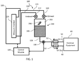
- FIG. 1 is a block diagram illustrating a trace gas measurement apparatus that can be implemented within one or more embodiments of the present invention.
- the trace gas measurement apparatus 100 is connectable to and communicates directly with electrical equipment 40. This communication may be performed in real-time, on-line during operation of the electrical equipment 40.
- the trace gas measurement apparatus 100 may be disposed in direct contact with the electrical equipment 40 or in a remote location while maintaining communication with the electrical equipment 40.
- the present invention is not limited to the trace gas measurement apparatus 100 being disposed in any particular location, the location may be any location suitable for the purposes set forth herein. Further, the present invention is not limited to the electrical equipment including any particular type or number of electrical equipment components (e.g., transformers, tap changers, and/or circuit breakers), and may vary accordingly.
- the trace gas measurement apparatus 100 includes at least one sample cell 200 corresponding to and connectable to the electrical equipment 40, and including a head space 203 and an oil sample 205 housed therein.
- the sample cell 200 collects the oil sample 205 of insulating oil flowing through the electrical equipment 40, from which trace gases 206 are to be extracted for analysis.
- a laser- based sensor or other sensor system may be employed for receiving the trace gases from the sample cell 200 and performing the trace gas detection process, to determine the health of the electrical equipment 40.
- an infrared (IR) absorption based technology system including a laser and a photodiode may be used.
- the trace gas measurement apparatus 100 further includes an oil pump 108 connected with the sample cell 200 for selectively pumping oil into or out of the sample cell when necessary, via forward and return oil flow lines 50 and 60 connecting to the electrical equipment 40.
- the forward and return oil flow lines 50 and 60 respectively including valves 52 and 62, for controlling the flow of oil to the oil pump 108 from the electrical equipment 40, and from the oil pump 108 to the electrical equipment 40.
- the oil pump 108 is a reversible type oil pump for selectively reversing the operation thereof, to either pump oil into or out of the sample cell 200.
- the oil pump 108 is not limited to any particular type of reversible pump. Further, alternatively, separate pumps may be used to separately pump oil into and out of the sample cell 200. Any pump(s) suitable for the purpose set forth herein may be employed.
- valves 52 and 62 are non-reversible valves (NRVs) which prevent oil being supplied from the electrical equipment 40 or to the electrical equipment 40 from reversing in direction and causing damage to the extraction process.
- NSVs non-reversible valves
- the present invention is not limited to any particular type or number of valves, any type or number of valves suitable for the purpose set forth herein may be employed.
- a plurality of valves 110 and 112 within respective forward and return gas paths 115 and 118 are provided.
- the forward and return gas paths 115 and 118 connect the sample cell 200 to an analysis module 120, for performing measurements and analysis on trace gases 206 extracted within the sample cell 200.
- the analysis module 120 includes a measure chamber 125 for receiving trace gases 206 therein, and performing dissolved gas analysis (DGA).
- a control mechanism (not shown) may be provided for controlling the stop and start of flow and amount of flow within the forward and return paths 115 and 118.
- a control module 130 is also provided in communication with the analysis module 120, and oil pump 108 and controls operations within the trace gas measurement apparatus 100.
- the oil sample 205 in the sample cell 200 is supplied via the forward flow line 50 from the electrical equipment 40 to the sample cell 200 during operation of the trace gas measurement apparatus 100.
- the oil sample 205 resides in the sample cell 200 for a predetermined period of time during which a measurement and analysis operation is to be performed.
- a single sample cell 200 is provided, a plurality of sample cells 200 may be provided to accommodate multiple electrical equipment components as needed. Alternatively, multiple electrical equipment components may be connected to a single sample cell 200.
- FIGs. 2A through 2D are detailed schematics of a sample cell 200 which may be employed within the trace gas measurement apparatus 100 of FIG. 1 , illustrating operations thereof that can be implemented within one or more embodiments of the present invention.
- the sample cell 200 comprises a housing 202 having a lower section 202a and an upper section 202b, for housing an oil sample 205 therein.
- the oil sample 205 enters the sample cell 200 through an opening in the lower section 202a.
- the sample cell 200 further includes a plurality of perforated sheets or porous sheets 210 including 210a, 210b and 210c disposed in a fixed horizontal manner by a fixing means (not shown) within the upper section 202b of the housing 202 in the head space region 203.
- the perforated sheets 210 are spaced a predetermined distance apart.
- the position and the predetermined distance apart of each perforated sheet 210 can be determined by several different factors.
- the position of the highest perforated sheet 210c can be at the reduced oil level that allows the air volume within the measure chamber 125 and connecting piping to achieve the air pressure required (e.g., approximately 0.3 bar absolute), using the lowest volumetric ratio (i.e., ratio of oil-to- air volume).
- the lowest perforated sheet 210a can be placed using the same criteria as that above, but applying the highest volumetric ratio to be achieved, starting the oil level before draw down at a lower level will then expand the ratio of oil-to-air volume, and hence a lower final position once the air pressure is achieved.
- more perforated sheets 210 can be placed above the highest placed sheet 210c.
- additional perforated sheets 210 can be placed below the highest sheet 210c at a regular or irregular interval to below the position of the lowest perforated sheet 210a as described above.
- An oil receiving portion 215 extends in a vertical direction through the housing 202, and receives new oil samples from the electrical equipment 40 via line 109 as depicted in FIG. 1 .
- the oil receiving portion 215 may be in the form of a tube or piping for receiving and transmitting oil to the sample cell 200.
- a separate oil output portion 218 is also included in the sample cell 200 for outputting existing oil samples from the sample cell 200. The inputting of new oil samples and outputting of existing oil samples is controlled by the control module 130 (as depicted in FIG. 1 ).
- valve 52 in operation of the sample cell 200, valve 52 (as depicted in FIG. 1 ) is open to allow an oil sample 205 from the electrical equipment 40 to be drawn and pumped via the oil pump 108 into the sample cell 200.
- oil portions 230a, 230b and 230c (as depicted in FIG. 2C ) of the oil sample 230 are pumped successively via the oil pump 108 through the oil receiving portion 215 and into the upper section 205b (see arrows 'A') and are disposed on the first, second and third perforated sheets 210a, 210b and 210c.
- the oil level rises over the perforated sheets 210 and when the oil level is dropped the perforated sheet 210 is coated with a thin film of oil on the upper and bottom side of the sheet increasing the surface area for extracting the trace gases.
- the surface area i.e., the head space 203 as depicted in FIG. 2B ) for the extraction process is minimized since the oil level is at its maximum level.
- the perforated sheets 210 prevent the new oil sample 230 from mixing and recirculation with the existing oil sample 205.
- the present invention is not limited to any particular number, thickness or type of perforated sheets and may vary accordingly.
- the perforated sheets may be formed of any porous medium such as ceramic disc, steel wool, etc.
- the perforated sheets may be bent perforated sheets (e.g., an upturned U shape) arranged in a circular form or a stack of perforated sheets as shown in FIG. 2A .
- the existing oil sample 205 is pumped out from oil output portion 218 in the lower section 202a of the housing 202, leaving the new oil sample 230, closest to the oil surface in the sample cell 200. Then, the oil remaining in the sample cell 200 is equalised, to thereby obtain trace gases 206 (as depicted in FIG. 1 ).
- the process is repeated multiple cycles by adding new oil sample 230 and pumping out existing oil sample 205 and extracting trace gases 206 (as depicted in FIG. 1 ) from the oil sample remaining in the sample cell 200.
- the oil pump 108 as depicted in FIG. 1 provides a volume pressure which further assist in extracting gas from the oil samples 205, 230.
- the present invention provides the advantage of being able to extract an increased amount of trace gases at a faster rate of time.
- a sequence is formed that allows a progressive rate of extraction, which is dependent on a number of factors including surface area of the perforated sheets, oil and/or air pressure drop, oil type, pumping rate, and temperature, etc.
- each additional perforated sheet (approximately 65% open area) increases the surface area by approximately 70% (35% coating on top & bottom surfaces) dependent on the open area and thickness of the perforated sheets, thereby expediting the extraction process.
- FIGs. 3A through 3F are block diagrams of the trace gas measurement apparatus of FIG. 1 , illustrating trace gas extraction operations thereof that can be implemented within one or more embodiments of the present invention.
- a flushing operation is performed by inputting a new ambient gas sample (i.e., atmospheric air sample) which contains an amount of trace gases into the apparatus 100 via the valve 112.
- the oil level is dropped in the sample cell 200 is dropped by pumping the oil out (as depicted by arrow 'B') and the valve 112 is opened to receive the air sample, and air within the measure chamber 125 is also drawn into the sample cell 200 via the valve 110.
- valve 110 After measuring the trace gases (not shown) within the air sample, to exhaust the air sample, valve 110 is opened, air is pushed out through the valve 110 by filling the oil level with new oil 230 as shown in FIG. 3B (see arrows 'A').
- the sample cell 200 is filled to a top surface with oil from oil sample 205 and the valves 110 and 112 are closed.
- the oil is pumped from the sample cell 200 via the oil output portion 218 as depicted in FIG. 2D (see arrows 'B'), and new oil sample 230 is input into the sample cell 200, and the air pressure is dropped to approximately 0.3 bar absolute inside the sample cell 200.
- the trace gases 206 are measured.
- the air pressure may be dropped for multiple cycles within a range of 0.8 bar to 0.5 bar, and then take a measurement at approximately 0.3 bar.
- FIGS. 3A through 3F more new oil sample 230 is input into the sample cell 200 via the oil receiving portion 215 (see arrows 'A') and the sample cell 200 is filled to the top surface again with oil as shown in FIG. 3C , and the process is then continuously repeated multiple cycles, to allow trace gases to be extracted from the oil in the sample cell 200 as desired.
- the extraction process as shown in FIGS. 3A through 3F is for a lower detection limit (LDL) for detecting trace gases such as approximately 1ppm (parts per million).
- LDL lower detection limit
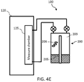
- FIGs. 4A through 4E will describe an extraction process for a higher detection limit (HDL) of approximately 50,000 ppm that can be implemented within one or more alternative embodiments of the present invention.
- HDL detection limit
- the measuring parameters are adjustable.
- the measuring parameters include the starting oil level and the air pressure within the sample cell 200.
- the measuring parameters are not limited hereto and may include other parameters suitable for the purpose set forth herein.
- the sample cell 200 Prior to initiating the extracting process, the sample cell 200 is prepared similar to that shown in FIGS. 3A and 3B , thus, the preparation process is the same in FIGS. 4A and 4B , and detailed description thereof is omitted.
- a flushing operation is performed by receiving an ambient air sample in the sample cell 200 in FIG. 4A ; and the sample cell 200 is filled with oil as shown in FIG. 4B , to exhaust the ambient air sample out via the valve 110.
- the extraction process according to this alternative embodiment begins at FIG. 4C , where the oil level within the sample cell 200 is adjusted to a certain level less than full, such as half or three-fourths by pumping oil out of the sample cell 200 via the oil pump 108 depicted in FIG. 1 . In this embodiment, more air space is allotted at the top of the sample cell 200 in the head space 203.
- the air pressure is dropped to approximately 0.3 bar, and as shown in FIG. 4E , the trace gases 206 are extracted at the adjusted parameters.
- the present invention is not limited to the parameters including any particular oil level or drop in air pressure and may vary as necessary to be able to extract the amount of trace gases desired.
- the control module 130 includes a microcontroller or microprocessor programmed with computer software for controlling the extraction process and performing analysis of the trace gases 206 when supplied to the analysis module 120.
- the control module 130 controls the operation of the analysis module 120 and the oil pump 108.
- the control module 130 may be any type of computing device capable of performing the operations of the present invention.
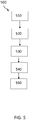
- FIG. 5 is a flow diagram illustrating an exemplary trace gas extraction method 500 as illustrated in FIGs. 3A through 3F , implementing an embodiment of the present invention.
- the process begins at operation 510, where the oil chamber is emptied from the previous trace gases, by lowering the oil level while open to draw in ambient air, through the measure chamber, so that the system is purged ( FIG. 3A ).
- the process continues to operation 520, where the measure chambers valves are closed, allowing a measurement of the trace gases within the air sample to be performed, and the air sample is then returned to the oil sample in the sample cell, via an air pump or by cycling the measure chamber valves when lowering & raising the oil level, to drive the main air circulation within the measure chamber one direction, to thereby prepare the sample cell for the extraction process ( FIG. 3B ).
- the sample cell filled with oil sample and the sample cell is closed off by closing valves connected therewith ( FIG. 3C ), and the trace gases will be extracted.
- operation, 540 some of the oil from the oil sample is pumped out of the sample cell and new oil is pumped into the sample cell ( FIG. 3D ).
- the new oil portions as shown in FIG. 2C are separated by the perforated sheets fixed within the sample cell.
- operation 550 the oil is further pumped out of the sample cell, and the air pressure is dropped to a predetermined amount ( FIG. 3E ). Then, in operation 550, the trace gases are measured.
- the method 500 then returns to operation 530 ( FIG. 3F ) by filling the sample cell to a top surface thereof with oil, and repeating operations 530 through 550 to obtain the desired amount of trace gases for analysis.
- FIG. 6 is a flow diagram illustrating an exemplary trace gas extraction method 600 as illustrated in FIGs.4A through 4E , implementing an alternative embodiment of the present invention.
- the method 600 begins at operation 610 where prior to initiating the extraction process, an air sample is received in the sample cell and trace gas extraction is performed on the air sample ( FIG. 4A ) and the sample cell is then filled with oil to exhaust the air sample out of the sample cell ( FIG. 4B ).
- the process continues to operation 620 where the oil level within the sample cell is adjusted to a certain level less than full, such as half or three-fourth by pumping oil out of the sample cell using an oil pump.
- the air pressure within the sample cell is dropped to a certain level (e.g., 0.3 bar) and trace gases are extracted at the adjusted parameters (i.e., the oil level and the air pressure) for higher detection limit (HDL) of trace gases.
- a certain level e.g., 0.3 bar
- trace gases are extracted at the adjusted parameters (i.e., the oil level and the air pressure) for higher detection limit (HDL) of trace gases.
- the measurement apparatus of the present invention may be used in an on line measurement type arrangement with electrical equipment such as a main transformer and/or tank changer.
- the measurement apparatus may further be implemented in real-time to determine the condition of the total electrical system (e.g., a transformer system). These faults can be detected early, to minimize cost associated with unplanned outages and any electrical equipment failure.
Landscapes
- Life Sciences & Earth Sciences (AREA)
- Health & Medical Sciences (AREA)
- Chemical & Material Sciences (AREA)
- Physics & Mathematics (AREA)
- Biochemistry (AREA)
- Analytical Chemistry (AREA)
- Pathology (AREA)
- General Health & Medical Sciences (AREA)
- General Physics & Mathematics (AREA)
- Immunology (AREA)
- Engineering & Computer Science (AREA)
- Molecular Biology (AREA)
- Biomedical Technology (AREA)
- Food Science & Technology (AREA)
- Medicinal Chemistry (AREA)
- Spectroscopy & Molecular Physics (AREA)
- Hydrology & Water Resources (AREA)
- Chemical Kinetics & Catalysis (AREA)
- General Chemical & Material Sciences (AREA)
- Oil, Petroleum & Natural Gas (AREA)
- Combustion & Propulsion (AREA)
- Sampling And Sample Adjustment (AREA)
Abstract
Description
- The present invention relates generally to trace gas measurement apparatus. In particularly, the present invention relates to extracting trace gases from insulating oil in electrical equipment.
- Trace gas in electrical equipment is typically generated from electrical insulating oil used in electrical equipment, which generates and distributes electrical power. Some examples of electrical equipment include transformers, tap-changers and circuit breakers. When a fault occurs within the electrical equipment a trace gas (i.e., a fault gas) may be generated in the electrical insulating oil. The trace gases are extracted from an oil sample obtained from the electrical equipment and measured by a measurement device. The trace gas measurements are used to provide an operational and health status of the electrical equipment.
- For example, in a transformer, when faults e.g., arcing and overheating occur, gases such as methane and carbon dioxide or carbon monoxide are present in the insulating oil of the transformer. Measurements of these trace gases can be used to determine the type and the severity of the faults which occur in the electrical equipment.
- A measurement device such as a photo-acoustic spectroscopy are typically used to obtain trace gas measurements where small vibrations of the molecules in trace gases are generated when subjected to a particular infrared (IR) frequencies of light. In conventional methods, the trace gas extraction process may be a difficult and time-consuming process.
- The various embodiments of the present disclosure are configured to provide trace gas measurement apparatus having a sample implementing an extraction process including performing continuous sampling, to minimize equalisation time of the trace gases.
- In one exemplary embodiment, a trace gas measurement apparatus is provided. The trace gas measurement apparatus for electrical equipment that includes at least one sample cell configured to collect an oil sample from the electrical equipment. The sample cell having an oil receiving portion for receiving an oil sample, at least one perforated sheet or porous sheet within a head space thereof for receiving the oil sample from the oil receiving portion, housing the oil sample thereon, and separating a new oil sample received from an existing oil sample within the at least one sample cell. The trace gas measurement apparatus also includes an oil pump for selectively pumping oil into and out of the sample cell; and a control module controlling operation of the oil pump, to adjust an oil level and air pressure within the sample cell, for performing an extraction process of trace gases within the oil sample.
- In another exemplary embodiment, a method of extracting trace gases in insulating oil of electrical equipment is provided. The method includes performing a flushing operation of the sample cell; pumping oil into the sample cell and filling the sample cell to a top surface thereof; pumping a portion of the oil out of the sample cell, and pumping new oil sample into an upper section of the sample cell; resting the new oil sample on at least one perforated sheet or porous sheet disposed within the upper section of the sample cell, adjacent to a top surface of the portion of the oil remaining therein; and adjusting air pressure within the sample cell, for extracting the trace gases.
- In another exemplary embodiment, an alternative method of extracting gases in insulating oil of electrical equipment is provided. The method includes performing a flushing operation of the sample cell; pumping oil into the sample cell and filling the sample cell to a certain level less than full; and adjusting air pressure within the sample cell, for extracting the trace gases.
- The foregoing has broadly outlined some of the aspects and features of various embodiments, which should be construed to be merely illustrative of various potential applications of the disclosure. Other beneficial results can be obtained by applying the disclosed information in a different manner or by combining various aspects of the disclosed embodiments. Accordingly, other aspects and a more comprehensive understanding may be obtained by referring to the detailed description of the exemplary embodiments taken in conjunction with the accompanying drawings, in addition to the scope defined by the claims.
-
-
FIG. 1 is a block diagram illustrating a trace gas measurement apparatus that can be implemented within one or more embodiments of the present invention. -
FIGs. 2A through 2D are detailed schematics of a sample cell of the trace gas measurement apparatus ofFIG. 1 , illustrating operations thereof that can be implemented within one or more embodiments of the present invention. -
FIGs. 3A through 3F are block diagrams of the trace gas measurement apparatus ofFIG. 1 , illustrating trace gas extraction operations thereof that can be implemented within one or more embodiments of the present invention. -
FIGs. 4A through 4E are block diagrams of the trace gas measurement apparatus ofFIG. 1 , illustrating trace gas extraction operations thereof that can be implemented within one or more alternative embodiments of the present invention. -
FIG. 5 is a flow diagram illustrating an exemplary trace gas extraction method illustrated inFIGs. 3A through 3F , implementing an embodiment of the present invention. -
FIG. 6 is a flow diagram illustrating an exemplary trace gas extraction method illustrated inFIGs. 4A through 4E , implementing an alternative embodiment of the present invention. - The drawings are only for purposes of illustrating preferred embodiments and are not to be construed as limiting the disclosure. Given the following enabling description of the drawings, the novel aspects of the present disclosure should become evident to a person of ordinary skill in the art. This detailed description uses numerical and letter designations to refer to features in the drawings. Like or similar designations in the drawings and description have been used to refer to like or similar parts of embodiments of the invention.
- As required, detailed embodiments are disclosed herein. It must be understood that the disclosed embodiments are merely exemplary of various and alternative forms. As used herein, the word "exemplary" is used expansively to refer to embodiments that serve as illustrations, specimens, models, or patterns. The figures are not necessarily to scale and some features may be exaggerated or minimized to show details of particular components. In other instances, well-known components, systems, materials, or methods that are known to those having ordinary skill in the art have not been described in detail in order to avoid obscuring the present disclosure. Therefore, specific structural and functional details disclosed herein are not to be interpreted as limiting, but merely as a basis for the claims and as a representative basis for teaching one skilled in the art.
- Exemplary embodiments of the present invention provides a trace gas measurement apparatus for performing dissolved gas analysis (DGA) on electrical insulating oil flowing within electrical equipment (e.g., transformers, circuit breakers, or tap changers). The trace gas measurement apparatus may be implemented within a portable gas analyzer (PGA). The DGA process is used to determine the health (e.g., the occurrence any faults or failure) of the electrical equipment and the current state of operation thereof. The trace gas measurement apparatus effectively performs trace gas extraction from oil supplied to the sample cell by continuously sampling of the oil and adjusting the surface area (i.e., head space) using perforated sheets within the sample cell and by adjusting the air pressure level. Therefore, the extraction methods of the present invention provide the advantages of decreasing the equalisation time and increasing the amount of trace gases extracted.
-
FIG. 1 is a block diagram illustrating a trace gas measurement apparatus that can be implemented within one or more embodiments of the present invention. As shown inFIG. 1 , the tracegas measurement apparatus 100 is connectable to and communicates directly withelectrical equipment 40. This communication may be performed in real-time, on-line during operation of theelectrical equipment 40. The tracegas measurement apparatus 100 may be disposed in direct contact with theelectrical equipment 40 or in a remote location while maintaining communication with theelectrical equipment 40. The present invention is not limited to the tracegas measurement apparatus 100 being disposed in any particular location, the location may be any location suitable for the purposes set forth herein. Further, the present invention is not limited to the electrical equipment including any particular type or number of electrical equipment components (e.g., transformers, tap changers, and/or circuit breakers), and may vary accordingly. - The trace
gas measurement apparatus 100 includes at least onesample cell 200 corresponding to and connectable to theelectrical equipment 40, and including ahead space 203 and anoil sample 205 housed therein. The sample cell
200 collects theoil sample 205 of insulating oil flowing through theelectrical equipment 40, from whichtrace gases 206 are to be extracted for analysis. A laser- based sensor or other sensor system may be employed for receiving the trace gases from thesample cell 200 and performing the trace gas detection process, to determine the health of theelectrical equipment 40. For example, an infrared (IR) absorption based technology system including a laser and a photodiode may be used. - The trace
gas measurement apparatus 100 further includes anoil pump 108 connected with thesample cell 200 for selectively pumping oil into or out of the sample cell when necessary, via forward and returnoil flow lines electrical equipment 40. The forward and returnoil flow lines valves oil pump 108 from theelectrical equipment 40, and from theoil pump 108 to theelectrical equipment 40. - According to embodiments, the
oil pump 108 is a reversible type oil pump for selectively reversing the operation thereof, to either pump oil into or out of thesample cell 200. Theoil pump 108 is not limited to any particular type of reversible pump. Further, alternatively, separate pumps may be used to separately pump oil into and out of thesample cell 200. Any pump(s) suitable for the purpose set forth herein may be employed. - Further, the
valves electrical equipment 40 or to theelectrical equipment 40 from reversing in direction and causing damage to the extraction process. The present invention is not limited to any particular type or number of valves, any type or number of valves suitable for the purpose set forth herein may be employed. - Further, a plurality of
valves gas paths gas paths sample cell 200 to ananalysis module 120, for performing measurements and analysis ontrace gases 206 extracted within thesample cell 200. - The
analysis module 120 includes ameasure chamber 125 for receivingtrace gases 206 therein, and performing dissolved gas analysis (DGA). A control mechanism (not shown) may be provided for controlling the stop and start of flow and amount of flow within the forward and returnpaths - A
control module 130 is also provided in communication with theanalysis module 120, andoil pump 108 and controls operations within the tracegas measurement apparatus 100. - Further as shown, the
oil sample 205 in thesample cell 200 is supplied via theforward flow line 50 from theelectrical equipment 40 to thesample cell 200 during operation of the tracegas measurement apparatus 100. Theoil sample 205 resides in thesample cell 200 for a predetermined period of time during which a measurement and analysis operation is to be performed. Although asingle sample cell 200 is provided, a plurality ofsample cells 200 may be provided to accommodate multiple electrical equipment components as needed. Alternatively, multiple electrical equipment components may be connected to asingle sample cell 200. -
FIGs. 2A through 2D are detailed schematics of asample cell 200 which may be employed within the tracegas measurement apparatus 100 ofFIG. 1 , illustrating operations thereof that can be implemented within one or more embodiments of the present invention. - As shown in
FIG. 2A , thesample cell 200 comprises ahousing 202 having alower section 202a and anupper section 202b, for housing anoil sample 205 therein. Theoil sample 205 enters thesample cell 200 through an opening in thelower section 202a. Thesample cell 200 further includes a plurality of perforated sheets orporous sheets 210 including 210a, 210b and 210c disposed in a fixed horizontal manner by a fixing means (not shown) within theupper section 202b of thehousing 202 in thehead space region 203. Theperforated sheets 210 are spaced a predetermined distance apart. - According to embodiments of the present invention, the position and the predetermined distance apart of each
perforated sheet 210 can be determined by several different factors. For example, the position of the highestperforated sheet 210c can be at the reduced oil level that allows the air volume within themeasure chamber 125 and connecting piping to achieve the air pressure required (e.g., approximately 0.3 bar absolute), using the lowest volumetric ratio (i.e., ratio of oil-to- air volume). - The lowest
perforated sheet 210a can be placed using the same criteria as that above, but applying the highest volumetric ratio to be achieved, starting the oil level before draw down at a lower level will then expand the ratio of oil-to-air volume, and hence a lower final position once the air pressure is achieved. To increase the surface area of theperforated sheets 210 to be coated with oil, moreperforated sheets 210 can be placed above the highest placedsheet 210c. To decrease mixing of existing and new oil samples, additionalperforated sheets 210 can be placed below thehighest sheet 210c at a regular or irregular interval to below the position of the lowestperforated sheet 210a as described above. - An
oil receiving portion 215 extends in a vertical direction through thehousing 202, and receives new oil samples from theelectrical equipment 40 vialine 109 as depicted inFIG. 1 . According to an embodiment, theoil receiving portion 215 may be in the form of a tube or piping for receiving and transmitting oil to thesample cell 200. A separateoil output portion 218 is also included in thesample cell 200 for outputting existing oil samples from thesample cell 200. The inputting of new oil samples and outputting of existing oil samples is controlled by the control module 130 (as depicted inFIG. 1 ). - As shown in
FIGS. 2B through 2D , in operation of thesample cell 200, valve 52 (as depicted inFIG. 1 ) is open to allow anoil sample 205 from theelectrical equipment 40 to be drawn and pumped via theoil pump 108 into thesample cell 200. When anew oil sample 230 is desired during the measurement process,oil portions FIG. 2C ) of theoil sample 230 are pumped successively via theoil pump 108 through theoil receiving portion 215 and into the upper section 205b (see arrows 'A') and are disposed on the first, second and thirdperforated sheets - Further as shown in
FIG. 2B , when theoil sample 230 is pumped into thesample cell 200, the oil level rises over theperforated sheets 210 and when the oil level is dropped theperforated sheet 210 is coated with a thin film of oil on the upper and bottom side of the sheet increasing the surface area for extracting the trace gases. As shown inFIG. 2C , the surface area (i.e., thehead space 203 as depicted inFIG. 2B ) for the extraction process is minimized since the oil level is at its maximum level. - The
perforated sheets 210 prevent thenew oil sample 230 from mixing and recirculation with the existingoil sample 205. The present invention is not limited to any particular number, thickness or type of perforated sheets and may vary accordingly. For example, the perforated sheets may be formed of any porous medium such as ceramic disc, steel wool, etc. For example, the perforated sheets may be bent perforated sheets (e.g., an upturned U shape) arranged in a circular form or a stack of perforated sheets as shown inFIG. 2A . - Next in
FIG. 2D , when thetrace gases 206 as depicted inFIG. 1 are to be extracted, the existingoil sample 205 is pumped out fromoil output portion 218 in thelower section 202a of thehousing 202, leaving thenew oil sample 230, closest to the oil surface in thesample cell 200. Then, the oil remaining in thesample cell 200 is equalised, to thereby obtain trace gases 206 (as depicted inFIG. 1 ). The process is repeated multiple cycles by addingnew oil sample 230 and pumping out existingoil sample 205 and extracting trace gases 206 (as depicted inFIG. 1 ) from the oil sample remaining in thesample cell 200. Theoil pump 108 as depicted inFIG. 1 , provides a volume pressure which further assist in extracting gas from theoil samples - The present invention provides the advantage of being able to extract an increased amount of trace gases at a faster rate of time. According to one or more embodiments, when multiple cycles are used, a sequence is formed that allows a progressive rate of extraction, which is dependent on a number of factors including surface area of the perforated sheets, oil and/or air pressure drop, oil type, pumping rate, and temperature, etc.
- However, in testing without using additional surface area of the perforated sheets, and driving down to 0.7 bar, this resulted in approximately 6.5% of the final concentration of trace gases extracted after 1 minutes, after 8 minutes there was approximately 49% of the final concentration of trace gases (2 cycles), and after 17 minutes (4 cycles), there was approximately 67% of the final concentration. Each additional perforated sheet (approximately 65% open area) increases the surface area by approximately 70% (35% coating on top & bottom surfaces) dependent on the open area and thickness of the perforated sheets, thereby expediting the extraction process.
- Additional details regarding the extraction process will be discussed below with reference to
FIGS. 3A through 3F , and4A through 4E . -
FIGs. 3A through 3F are block diagrams of the trace gas measurement apparatus ofFIG. 1 , illustrating trace gas extraction operations thereof that can be implemented within one or more embodiments of the present invention. As shown inFIG. 3A , at the initiation of the extraction process, a flushing operation is performed by inputting a new ambient gas sample (i.e., atmospheric air sample) which contains an amount of trace gases into theapparatus 100 via thevalve 112. The oil level is dropped in thesample cell 200 is dropped by pumping the oil out (as depicted by arrow 'B') and thevalve 112 is opened to receive the air sample, and air within themeasure chamber 125 is also drawn into thesample cell 200 via thevalve 110. - After measuring the trace gases (not shown) within the air sample, to exhaust the air sample,
valve 110 is opened, air is pushed out through thevalve 110 by filling the oil level withnew oil 230 as shown inFIG. 3B (see arrows 'A'). - As shown in
FIG. 3C , to initiate the extraction process, thesample cell 200 is filled to a top surface with oil fromoil sample 205 and thevalves FIG. 3D , the oil is pumped from thesample cell 200 via theoil output portion 218 as depicted inFIG. 2D (see arrows 'B'), andnew oil sample 230 is input into thesample cell 200, and the air pressure is dropped to approximately 0.3 bar absolute inside thesample cell 200. InFIG. 3E , thetrace gases 206 are measured. According to alternative embodiments of the present invention, the air pressure may be dropped for multiple cycles within a range of 0.8 bar to 0.5 bar, and then take a measurement at approximately 0.3 bar. - Next in
Fig. 3F , morenew oil sample 230 is input into thesample cell 200 via the oil receiving portion 215 (see arrows 'A') and thesample cell 200 is filled to the top surface again with oil as shown inFIG. 3C , and the process is then continuously repeated multiple cycles, to allow trace gases to be extracted from the oil in thesample cell 200 as desired. The extraction process as shown inFIGS. 3A through 3F is for a lower detection limit (LDL) for detecting trace gases such as approximately 1ppm (parts per million). -
FIGs. 4A through 4E will describe an extraction process for a higher detection limit (HDL) of approximately 50,000 ppm that can be implemented within one or more alternative embodiments of the present invention. - As an alternative extraction process from that shown in
FIGS. 3A through 3F , inFIGS. 4A through 4E , the measuring parameters are adjustable. The measuring parameters include the starting oil level and the air pressure within thesample cell 200. The measuring parameters are not limited hereto and may include other parameters suitable for the purpose set forth herein. - Prior to initiating the extracting process, the
sample cell 200 is prepared similar to that shown inFIGS. 3A and 3B , thus, the preparation process is the same inFIGS. 4A and 4B , and detailed description thereof is omitted. A flushing operation is performed by receiving an ambient air sample in thesample cell 200 inFIG. 4A ; and thesample cell 200 is filled with oil as shown inFIG. 4B , to exhaust the ambient air sample out via thevalve 110. The extraction process according to this alternative embodiment begins atFIG. 4C , where the oil level within thesample cell 200 is adjusted to a certain level less than full, such as half or three-fourths by pumping oil out of thesample cell 200 via theoil pump 108 depicted inFIG. 1 . In this embodiment, more air space is allotted at the top of thesample cell 200 in thehead space 203. - Next, as shown in
FIG. 4D , the air pressure is dropped to approximately 0.3 bar, and as shown inFIG. 4E , thetrace gases 206 are extracted at the adjusted parameters. The present invention is not limited to the parameters including any particular oil level or drop in air pressure and may vary as necessary to be able to extract the amount of trace gases desired. - As mentioned, the extraction processes are performed under the control of the
control system 130 as shown inFIG. 1 . Thecontrol module 130 includes a microcontroller or microprocessor programmed with computer software for controlling the extraction process and performing analysis of thetrace gases 206 when supplied to theanalysis module 120. Thecontrol module 130 controls the operation of theanalysis module 120 and theoil pump 108. Thecontrol module 130 may be any type of computing device capable of performing the operations of the present invention. -
FIG. 5 is a flow diagram illustrating an exemplary tracegas extraction method 500 as illustrated inFIGs. 3A through 3F , implementing an embodiment of the present invention. The process begins atoperation 510, where the oil chamber is emptied from the previous trace gases, by lowering the oil level while open to draw in ambient air, through the measure chamber, so that the system is purged (FIG. 3A ). - From
operation 510, the process continues tooperation 520, where the measure chambers valves are closed, allowing a measurement of the trace gases within the air sample to be performed, and the air sample is then returned to the oil sample in the sample cell, via an air pump or by cycling the measure chamber valves when lowering & raising the oil level, to drive the main air circulation within the measure chamber one direction, to thereby prepare the sample cell for the extraction process (FIG. 3B ). - Next, in
operation 530, to initiate the extraction process the sample cell filled with oil sample and the sample cell is closed off by closing valves connected therewith (FIG. 3C ), and the trace gases will be extracted. In operation, 540, some of the oil from the oil sample is pumped out of the sample cell and new oil is pumped into the sample cell (FIG. 3D ). According to embodiments, the new oil portions as shown inFIG. 2C , for example, are separated by the perforated sheets fixed within the sample cell. - From
operation 540, the process continues tooperation 550 where the oil is further pumped out of the sample cell, and the air pressure is dropped to a predetermined amount (FIG. 3E ). Then, inoperation 550, the trace gases are measured. - The
method 500, then returns to operation 530 (FIG. 3F ) by filling the sample cell to a top surface thereof with oil, and repeatingoperations 530 through 550 to obtain the desired amount of trace gases for analysis. -
FIG. 6 is a flow diagram illustrating an exemplary tracegas extraction method 600 as illustrated inFIGs.4A through 4E , implementing an alternative embodiment of the present invention. - The
method 600 begins atoperation 610 where prior to initiating the extraction process, an air sample is received in the sample cell and trace gas extraction is performed on the air sample (FIG. 4A ) and the sample cell is then filled with oil to exhaust the air sample out of the sample cell (FIG. 4B ). - From
operation 610, the process continues tooperation 620 where the oil level within the sample cell is adjusted to a certain level less than full, such as half or three-fourth by pumping oil out of the sample cell using an oil pump. - Next, in
operation 630, the air pressure within the sample cell is dropped to a certain level (e.g., 0.3 bar) and trace gases are extracted at the adjusted parameters (i.e., the oil level and the air pressure) for higher detection limit (HDL) of trace gases. - The measurement apparatus of the present invention may be used in an on line measurement type arrangement with electrical equipment such as a main transformer and/or tank changer. The measurement apparatus may further be implemented in real-time to determine the condition of the total electrical system (e.g., a transformer system). These faults can be detected early, to minimize cost associated with unplanned outages and any electrical equipment failure.
- This written description uses examples to disclose the invention, including the best mode, and also to enable any person skilled in the art to practice the invention, including making and using any devices or systems and performing any incorporated methods. The patentable scope of the invention is defined by the claims, and may include other examples that occur to those skilled in the art. Such other examples are intended to be within the scope of the claims if they have structural elements that do not differ from the literal language of the claims, or if they include equivalent structural elements with insubstantial differences from the literal languages of the claims.
- Various aspects and embodiments of the present invention are defined by the following numbered clauses:
- 1. A method of extracting trace gases from insulating oil in electrical equipment, the method comprising:
- performing a flushing operation of the sample cell;
- pumping oil into the sample cell and filling the sample cell to a certain level less than full; and
- 2. The method of clause 1, wherein the extraction process is a higher detection limit (HDL) process.
- 3. The method of clause 1 or 2, wherein the HDL process is for extracting approximately 50,000 parts per million (ppm) of trace gases.
Claims (16)
Applications Claiming Priority (1)
| Application Number | Priority Date | Filing Date | Title |
|---|---|---|---|
| US14/677,537 US9874497B2 (en) | 2015-04-02 | 2015-04-02 | Trace gas measurement apparatus for electrical equipment |
Publications (2)
| Publication Number | Publication Date |
|---|---|
| EP3076172A1 true EP3076172A1 (en) | 2016-10-05 |
| EP3076172B1 EP3076172B1 (en) | 2018-08-15 |
Family
ID=55646340
Family Applications (1)
| Application Number | Title | Priority Date | Filing Date |
|---|---|---|---|
| EP16161980.4A Active EP3076172B1 (en) | 2015-04-02 | 2016-03-23 | Trace gas measurement apparaus for electrical equipment |
Country Status (5)
| Country | Link |
|---|---|
| US (1) | US9874497B2 (en) |
| EP (1) | EP3076172B1 (en) |
| CN (1) | CN106053719B (en) |
| BR (1) | BR102016007041A2 (en) |
| CA (1) | CA2925252C (en) |
Families Citing this family (4)
| Publication number | Priority date | Publication date | Assignee | Title |
|---|---|---|---|---|
| US10670564B2 (en) | 2015-05-11 | 2020-06-02 | 9334-3275 Quebec Inc. | Photoacoustic detector |
| US10365209B1 (en) * | 2017-11-15 | 2019-07-30 | Morgan Schaffer Ltd. | Apparatus and method for performing dissolved gas analysis on a piece of electrical equipment using resonant photo-acoustic spectroscopy and use thereof |
| US11137382B2 (en) * | 2018-06-15 | 2021-10-05 | Morgan Schaffer Ltd. | Apparatus and method for performing gas analysis using optical absorption spectroscopy, such as infrared (IR) and/or UV, and use thereof in apparatus and method for performing dissolved gas analysis (DGA) on a piece of electrical equipment |
| CN110736640A (en) * | 2019-09-10 | 2020-01-31 | 内蒙古电力(集团)有限责任公司薛家湾供电局 | Oil storage monitoring device and monitoring method |
Citations (4)
| Publication number | Priority date | Publication date | Assignee | Title |
|---|---|---|---|---|
| JPS60253842A (en) * | 1984-05-30 | 1985-12-14 | Mitsubishi Electric Corp | Apparatus for monitoring dissolved gas in oil |
| US4944178A (en) * | 1988-04-18 | 1990-07-31 | Nissin Electric Co., Ltd | Apparatus and method for measuring dissolved gas in oil |
| DE19503802C1 (en) * | 1995-02-06 | 1996-03-14 | Siemens Ag | Device for measurement of hydrogen in transformer oil |
| US20030172716A1 (en) * | 2000-05-10 | 2003-09-18 | Eckhard Braesel | Method and device for the monitoring of gases |
Family Cites Families (29)
| Publication number | Priority date | Publication date | Assignee | Title |
|---|---|---|---|---|
| US3779066A (en) * | 1971-01-26 | 1973-12-18 | Us Agriculture | Determination of residual solvent in oilseed meals and flours by a volatilization procedure |
| US4385634A (en) | 1981-04-24 | 1983-05-31 | University Of Arizona Foundation | Radiation-induced thermoacoustic imaging |
| US4890478A (en) * | 1987-09-11 | 1990-01-02 | Westinghouse Electric Corp. | Gas-in-oil monitoring apparatus and method |
| US5633711A (en) | 1991-07-08 | 1997-05-27 | Massachusettes Institute Of Technology | Measurement of material properties with optically induced phonons |
| SE9102770L (en) * | 1991-09-25 | 1993-03-26 | Asea Brown Boveri | MONITORING OF LOST GAS IN OIL |
| US5400641A (en) * | 1993-11-03 | 1995-03-28 | Advanced Optical Controls, Inc. | Transformer oil gas extractor |
| US5749942A (en) * | 1997-02-14 | 1998-05-12 | Raychem Corporation | Apparatus for extracting a gas from a liquid and delivering the gas to a collection station |
| DE19833601C1 (en) | 1998-07-25 | 1999-12-23 | Eckhard Braesel | Method of detecting and establishing the origin of undissolved gases in liquid-filled high voltage systems |
| US6289716B1 (en) | 1998-08-19 | 2001-09-18 | Electric Power Research Institute, Inc. | Method for on-line assessment and indication of transformer conditions |
| US6391096B1 (en) | 2000-06-09 | 2002-05-21 | Serveron Corporation | Apparatus and method for extracting and analyzing gas |
| US6742384B2 (en) | 2002-07-02 | 2004-06-01 | Carrier Corporation | Trace gas management system for leak detection operations |
| EP1790965B1 (en) | 2005-11-29 | 2007-11-28 | Bräsel, Eckhard | Method for providing the gases dissolved in liquids from high-voltage systems for external analysis and device for carrying out this method |
| US8075675B2 (en) | 2008-06-12 | 2011-12-13 | Serveron Corporation | Apparatus and method for extracting gas from liquid |
| US8028561B2 (en) * | 2008-09-30 | 2011-10-04 | Qualitrol Company, Llc | Hydrogen sensor with air access |
| US8040518B2 (en) | 2008-10-07 | 2011-10-18 | Entanglement Technologies, Inc. | Cavity enhanced trace gas detection gradiometer |
| IT1397471B1 (en) * | 2010-01-14 | 2013-01-16 | Techimp Technologies S A Ora Techimp Technologies S R L | PROCEDURE AND DEVICE TO DERIVE THE CONCENTRATION OF A GAS DISSOLVED INTO AN ELECTRIC INSULATION OIL. |
| US8196448B2 (en) | 2010-01-20 | 2012-06-12 | GM Global Technology Operations LLC | Hydrogen sensor assembly |
| US8442775B2 (en) | 2010-04-02 | 2013-05-14 | Eduardo Pedrosa Santos | System and method for monitoring dissolved gases in insulating oil of high voltage equipment |
| US8395777B2 (en) | 2010-09-09 | 2013-03-12 | Adelphi University | Method and apparatus for trace gas detection using integrated wavelength modulated spectra across multiple lines |
| WO2012100246A1 (en) | 2011-01-23 | 2012-07-26 | Bpl Global, Ltd. | Electrical apparatus oil sampler and conditioner for solid state sensors |
| US8707767B2 (en) | 2011-03-31 | 2014-04-29 | Qualitrol Company, Llc | Combined hydrogen and pressure sensor assembly |
| ITBO20110670A1 (en) * | 2011-11-23 | 2013-05-24 | Techimp Technologies Srl | DEVICE FOR MEASURING THE CONCENTRATION OF A GAS DISSOLVED IN AN ELECTRIC INSULATION OIL |
| WO2013116799A1 (en) | 2012-02-01 | 2013-08-08 | Lumasense Technologies Holding, Inc. | System and method for monitoring asset health by dissolved gas measurement |
| EP2762857B1 (en) | 2012-12-19 | 2018-05-02 | General Electric Company | Method and device for dissolved gas analysis |
| EP2746747A1 (en) | 2012-12-21 | 2014-06-25 | ABB Research Ltd. | Sensor assembly and method for determining the hydrogen and moisture content of transformer oil |
| EP2778660A1 (en) | 2013-03-15 | 2014-09-17 | ABB Research Ltd. | Sensor assembly and method for sensing status condition of electrical equipment |
| JP6165343B2 (en) | 2013-09-12 | 2017-07-19 | コリア・アドバンスト・インスティテュート・オブ・サイエンス・アンド・テクノロジー | Hydrogen sensor element for measuring dissolved hydrogen gas concentration in liquid and method for measuring hydrogen gas concentration using the same |
| EP2988116B8 (en) * | 2014-08-19 | 2017-06-07 | ABB Schweiz AG | Optical sensor for detecting hydrogen in fluid and use of thin alloy film in the hydrogen sensor |
| US10024836B2 (en) * | 2015-03-26 | 2018-07-17 | General Electric Company | Trace gas measurement apparatus for electrical equipment |
-
2015
- 2015-04-02 US US14/677,537 patent/US9874497B2/en active Active
-
2016
- 2016-03-23 EP EP16161980.4A patent/EP3076172B1/en active Active
- 2016-03-29 CA CA2925252A patent/CA2925252C/en active Active
- 2016-03-30 BR BR102016007041A patent/BR102016007041A2/en not_active Application Discontinuation
- 2016-04-01 CN CN201610200432.6A patent/CN106053719B/en active Active
Patent Citations (4)
| Publication number | Priority date | Publication date | Assignee | Title |
|---|---|---|---|---|
| JPS60253842A (en) * | 1984-05-30 | 1985-12-14 | Mitsubishi Electric Corp | Apparatus for monitoring dissolved gas in oil |
| US4944178A (en) * | 1988-04-18 | 1990-07-31 | Nissin Electric Co., Ltd | Apparatus and method for measuring dissolved gas in oil |
| DE19503802C1 (en) * | 1995-02-06 | 1996-03-14 | Siemens Ag | Device for measurement of hydrogen in transformer oil |
| US20030172716A1 (en) * | 2000-05-10 | 2003-09-18 | Eckhard Braesel | Method and device for the monitoring of gases |
Also Published As
| Publication number | Publication date |
|---|---|
| EP3076172B1 (en) | 2018-08-15 |
| US9874497B2 (en) | 2018-01-23 |
| CA2925252C (en) | 2023-09-26 |
| US20160290896A1 (en) | 2016-10-06 |
| CN106053719B (en) | 2020-09-15 |
| CN106053719A (en) | 2016-10-26 |
| BR102016007041A2 (en) | 2016-10-04 |
| CA2925252A1 (en) | 2016-10-02 |
Similar Documents
| Publication | Publication Date | Title |
|---|---|---|
| CA2923936C (en) | Trace gas measurement apparatus for electrical equipment | |
| EP3076172B1 (en) | Trace gas measurement apparaus for electrical equipment | |
| EP2810041B1 (en) | System and method for monitoring asset health by dissolved gas measurement | |
| CN103149345B (en) | Detecting method and detecting device for intelligent dissolved gas-in-oil component | |
| US20120304734A1 (en) | In-oil gas concentration measuring system and in-oil gas concentration measuring method using same system | |
| CN104459411B (en) | A kind of bicavate transformer heat ageing real-time Simulation measurement apparatus and its application | |
| JP3343524B2 (en) | Gas analyzer in electrical insulating oil | |
| CN105259260A (en) | Novel transformer oil chromatography online monitoring device with three-way valve | |
| CN118376596A (en) | Real-time monitoring system, method, device and control processing equipment for gas relay | |
| KR102056234B1 (en) | Internal state detecting device for transformers | |
| CN212410421U (en) | Fault monitoring device with anti-noise function | |
| US20230390668A1 (en) | Apparatus and method for degassing a device, and corresponding test system for gas analysis | |
| CN112213277A (en) | Oil-immersed equipment oil way control method and device | |
| CN203101378U (en) | Testing device for gas-dissolved-in-oil intelligent component | |
| CN111790279A (en) | A device for extracting and dissolving gas in oil | |
| JP3170774B2 (en) | Oil-dissolved gas extractor, abnormality diagnosis device, and oil-filled electrical equipment | |
| CN116519858B (en) | Transformer oil nursing device with real-time monitoring function | |
| CN206557174U (en) | A kind of no carrier gas oil chromatography on-line monitoring system | |
| JPH1019879A (en) | Diagnosis of oil-filled electric machinery and portable diagnostic device therefor | |
| CN119470336A (en) | Transformer oil gas online monitoring device with oil mixing function and control method thereof | |
| KR102258418B1 (en) | An extracting gas supply line balance maintaining system of transformer oil | |
| JPS6020033Y2 (en) | gas analyzer | |
| CN117214421A (en) | Portable device for rapidly detecting dissolved acetylene in oil and operation method | |
| CN119480355A (en) | A degassing device and method for online monitoring of dissolved gas in transformer insulating oil | |
| JPS6385448A (en) | Analysis of dissolved gas in insulating oil |
Legal Events
| Date | Code | Title | Description |
|---|---|---|---|
| PUAI | Public reference made under article 153(3) epc to a published international application that has entered the european phase |
Free format text: ORIGINAL CODE: 0009012 |
|
| AK | Designated contracting states |
Kind code of ref document: A1 Designated state(s): AL AT BE BG CH CY CZ DE DK EE ES FI FR GB GR HR HU IE IS IT LI LT LU LV MC MK MT NL NO PL PT RO RS SE SI SK SM TR |
|
| AX | Request for extension of the european patent |
Extension state: BA ME |
|
| STAA | Information on the status of an ep patent application or granted ep patent |
Free format text: STATUS: REQUEST FOR EXAMINATION WAS MADE |
|
| STAA | Information on the status of an ep patent application or granted ep patent |
Free format text: STATUS: EXAMINATION IS IN PROGRESS |
|
| 17P | Request for examination filed |
Effective date: 20170405 |
|
| RBV | Designated contracting states (corrected) |
Designated state(s): AL AT BE BG CH CY CZ DE DK EE ES FI FR GB GR HR HU IE IS IT LI LT LU LV MC MK MT NL NO PL PT RO RS SE SI SK SM TR |
|
| 17Q | First examination report despatched |
Effective date: 20170512 |
|
| RIC1 | Information provided on ipc code assigned before grant |
Ipc: G01N 1/22 20060101ALI20180405BHEP Ipc: G01N 33/28 20060101AFI20180405BHEP |
|
| GRAP | Despatch of communication of intention to grant a patent |
Free format text: ORIGINAL CODE: EPIDOSNIGR1 |
|
| STAA | Information on the status of an ep patent application or granted ep patent |
Free format text: STATUS: GRANT OF PATENT IS INTENDED |
|
| INTG | Intention to grant announced |
Effective date: 20180516 |
|
| GRAS | Grant fee paid |
Free format text: ORIGINAL CODE: EPIDOSNIGR3 |
|
| GRAA | (expected) grant |
Free format text: ORIGINAL CODE: 0009210 |
|
| STAA | Information on the status of an ep patent application or granted ep patent |
Free format text: STATUS: THE PATENT HAS BEEN GRANTED |
|
| AK | Designated contracting states |
Kind code of ref document: B1 Designated state(s): AL AT BE BG CH CY CZ DE DK EE ES FI FR GB GR HR HU IE IS IT LI LT LU LV MC MK MT NL NO PL PT RO RS SE SI SK SM TR |
|
| REG | Reference to a national code |
Ref country code: CH Ref legal event code: EP Ref country code: GB Ref legal event code: FG4D Ref country code: AT Ref legal event code: REF Ref document number: 1030369 Country of ref document: AT Kind code of ref document: T Effective date: 20180815 |
|
| REG | Reference to a national code |
Ref country code: IE Ref legal event code: FG4D |
|
| REG | Reference to a national code |
Ref country code: DE Ref legal event code: R096 Ref document number: 602016004667 Country of ref document: DE |
|
| REG | Reference to a national code |
Ref country code: SE Ref legal event code: TRGR |
|
| REG | Reference to a national code |
Ref country code: NL Ref legal event code: MP Effective date: 20180815 |
|
| REG | Reference to a national code |
Ref country code: LT Ref legal event code: MG4D |
|
| REG | Reference to a national code |
Ref country code: AT Ref legal event code: MK05 Ref document number: 1030369 Country of ref document: AT Kind code of ref document: T Effective date: 20180815 |
|
| PG25 | Lapsed in a contracting state [announced via postgrant information from national office to epo] |
Ref country code: IS Free format text: LAPSE BECAUSE OF FAILURE TO SUBMIT A TRANSLATION OF THE DESCRIPTION OR TO PAY THE FEE WITHIN THE PRESCRIBED TIME-LIMIT Effective date: 20181215 Ref country code: AT Free format text: LAPSE BECAUSE OF FAILURE TO SUBMIT A TRANSLATION OF THE DESCRIPTION OR TO PAY THE FEE WITHIN THE PRESCRIBED TIME-LIMIT Effective date: 20180815 Ref country code: BG Free format text: LAPSE BECAUSE OF FAILURE TO SUBMIT A TRANSLATION OF THE DESCRIPTION OR TO PAY THE FEE WITHIN THE PRESCRIBED TIME-LIMIT Effective date: 20181115 Ref country code: LT Free format text: LAPSE BECAUSE OF FAILURE TO SUBMIT A TRANSLATION OF THE DESCRIPTION OR TO PAY THE FEE WITHIN THE PRESCRIBED TIME-LIMIT Effective date: 20180815 Ref country code: NL Free format text: LAPSE BECAUSE OF FAILURE TO SUBMIT A TRANSLATION OF THE DESCRIPTION OR TO PAY THE FEE WITHIN THE PRESCRIBED TIME-LIMIT Effective date: 20180815 Ref country code: NO Free format text: LAPSE BECAUSE OF FAILURE TO SUBMIT A TRANSLATION OF THE DESCRIPTION OR TO PAY THE FEE WITHIN THE PRESCRIBED TIME-LIMIT Effective date: 20181115 Ref country code: GR Free format text: LAPSE BECAUSE OF FAILURE TO SUBMIT A TRANSLATION OF THE DESCRIPTION OR TO PAY THE FEE WITHIN THE PRESCRIBED TIME-LIMIT Effective date: 20181116 Ref country code: FI Free format text: LAPSE BECAUSE OF FAILURE TO SUBMIT A TRANSLATION OF THE DESCRIPTION OR TO PAY THE FEE WITHIN THE PRESCRIBED TIME-LIMIT Effective date: 20180815 Ref country code: RS Free format text: LAPSE BECAUSE OF FAILURE TO SUBMIT A TRANSLATION OF THE DESCRIPTION OR TO PAY THE FEE WITHIN THE PRESCRIBED TIME-LIMIT Effective date: 20180815 |
|
| PG25 | Lapsed in a contracting state [announced via postgrant information from national office to epo] |
Ref country code: AL Free format text: LAPSE BECAUSE OF FAILURE TO SUBMIT A TRANSLATION OF THE DESCRIPTION OR TO PAY THE FEE WITHIN THE PRESCRIBED TIME-LIMIT Effective date: 20180815 Ref country code: LV Free format text: LAPSE BECAUSE OF FAILURE TO SUBMIT A TRANSLATION OF THE DESCRIPTION OR TO PAY THE FEE WITHIN THE PRESCRIBED TIME-LIMIT Effective date: 20180815 Ref country code: HR Free format text: LAPSE BECAUSE OF FAILURE TO SUBMIT A TRANSLATION OF THE DESCRIPTION OR TO PAY THE FEE WITHIN THE PRESCRIBED TIME-LIMIT Effective date: 20180815 |
|
| PG25 | Lapsed in a contracting state [announced via postgrant information from national office to epo] |
Ref country code: CZ Free format text: LAPSE BECAUSE OF FAILURE TO SUBMIT A TRANSLATION OF THE DESCRIPTION OR TO PAY THE FEE WITHIN THE PRESCRIBED TIME-LIMIT Effective date: 20180815 Ref country code: RO Free format text: LAPSE BECAUSE OF FAILURE TO SUBMIT A TRANSLATION OF THE DESCRIPTION OR TO PAY THE FEE WITHIN THE PRESCRIBED TIME-LIMIT Effective date: 20180815 Ref country code: IT Free format text: LAPSE BECAUSE OF FAILURE TO SUBMIT A TRANSLATION OF THE DESCRIPTION OR TO PAY THE FEE WITHIN THE PRESCRIBED TIME-LIMIT Effective date: 20180815 Ref country code: EE Free format text: LAPSE BECAUSE OF FAILURE TO SUBMIT A TRANSLATION OF THE DESCRIPTION OR TO PAY THE FEE WITHIN THE PRESCRIBED TIME-LIMIT Effective date: 20180815 Ref country code: PL Free format text: LAPSE BECAUSE OF FAILURE TO SUBMIT A TRANSLATION OF THE DESCRIPTION OR TO PAY THE FEE WITHIN THE PRESCRIBED TIME-LIMIT Effective date: 20180815 Ref country code: ES Free format text: LAPSE BECAUSE OF FAILURE TO SUBMIT A TRANSLATION OF THE DESCRIPTION OR TO PAY THE FEE WITHIN THE PRESCRIBED TIME-LIMIT Effective date: 20180815 |
|
| REG | Reference to a national code |
Ref country code: DE Ref legal event code: R097 Ref document number: 602016004667 Country of ref document: DE |
|
| PG25 | Lapsed in a contracting state [announced via postgrant information from national office to epo] |
Ref country code: SK Free format text: LAPSE BECAUSE OF FAILURE TO SUBMIT A TRANSLATION OF THE DESCRIPTION OR TO PAY THE FEE WITHIN THE PRESCRIBED TIME-LIMIT Effective date: 20180815 Ref country code: SM Free format text: LAPSE BECAUSE OF FAILURE TO SUBMIT A TRANSLATION OF THE DESCRIPTION OR TO PAY THE FEE WITHIN THE PRESCRIBED TIME-LIMIT Effective date: 20180815 Ref country code: DK Free format text: LAPSE BECAUSE OF FAILURE TO SUBMIT A TRANSLATION OF THE DESCRIPTION OR TO PAY THE FEE WITHIN THE PRESCRIBED TIME-LIMIT Effective date: 20180815 |
|
| PLBE | No opposition filed within time limit |
Free format text: ORIGINAL CODE: 0009261 |
|
| STAA | Information on the status of an ep patent application or granted ep patent |
Free format text: STATUS: NO OPPOSITION FILED WITHIN TIME LIMIT |
|
| 26N | No opposition filed |
Effective date: 20190516 |
|
| PG25 | Lapsed in a contracting state [announced via postgrant information from national office to epo] |
Ref country code: SI Free format text: LAPSE BECAUSE OF FAILURE TO SUBMIT A TRANSLATION OF THE DESCRIPTION OR TO PAY THE FEE WITHIN THE PRESCRIBED TIME-LIMIT Effective date: 20180815 |
|
| PG25 | Lapsed in a contracting state [announced via postgrant information from national office to epo] |
Ref country code: MC Free format text: LAPSE BECAUSE OF FAILURE TO SUBMIT A TRANSLATION OF THE DESCRIPTION OR TO PAY THE FEE WITHIN THE PRESCRIBED TIME-LIMIT Effective date: 20180815 |
|
| REG | Reference to a national code |
Ref country code: CH Ref legal event code: PL |
|
| PG25 | Lapsed in a contracting state [announced via postgrant information from national office to epo] |
Ref country code: LU Free format text: LAPSE BECAUSE OF NON-PAYMENT OF DUE FEES Effective date: 20190323 |
|
| REG | Reference to a national code |
Ref country code: BE Ref legal event code: MM Effective date: 20190331 |
|
| PG25 | Lapsed in a contracting state [announced via postgrant information from national office to epo] |
Ref country code: LI Free format text: LAPSE BECAUSE OF NON-PAYMENT OF DUE FEES Effective date: 20190331 Ref country code: CH Free format text: LAPSE BECAUSE OF NON-PAYMENT OF DUE FEES Effective date: 20190331 |
|
| PG25 | Lapsed in a contracting state [announced via postgrant information from national office to epo] |
Ref country code: BE Free format text: LAPSE BECAUSE OF NON-PAYMENT OF DUE FEES Effective date: 20190331 |
|
| PG25 | Lapsed in a contracting state [announced via postgrant information from national office to epo] |
Ref country code: TR Free format text: LAPSE BECAUSE OF FAILURE TO SUBMIT A TRANSLATION OF THE DESCRIPTION OR TO PAY THE FEE WITHIN THE PRESCRIBED TIME-LIMIT Effective date: 20180815 |
|
| PG25 | Lapsed in a contracting state [announced via postgrant information from national office to epo] |
Ref country code: PT Free format text: LAPSE BECAUSE OF FAILURE TO SUBMIT A TRANSLATION OF THE DESCRIPTION OR TO PAY THE FEE WITHIN THE PRESCRIBED TIME-LIMIT Effective date: 20181215 Ref country code: MT Free format text: LAPSE BECAUSE OF NON-PAYMENT OF DUE FEES Effective date: 20190323 |
|
| PG25 | Lapsed in a contracting state [announced via postgrant information from national office to epo] |
Ref country code: CY Free format text: LAPSE BECAUSE OF FAILURE TO SUBMIT A TRANSLATION OF THE DESCRIPTION OR TO PAY THE FEE WITHIN THE PRESCRIBED TIME-LIMIT Effective date: 20180815 |
|
| PG25 | Lapsed in a contracting state [announced via postgrant information from national office to epo] |
Ref country code: HU Free format text: LAPSE BECAUSE OF FAILURE TO SUBMIT A TRANSLATION OF THE DESCRIPTION OR TO PAY THE FEE WITHIN THE PRESCRIBED TIME-LIMIT; INVALID AB INITIO Effective date: 20160323 |
|
| PG25 | Lapsed in a contracting state [announced via postgrant information from national office to epo] |
Ref country code: MK Free format text: LAPSE BECAUSE OF FAILURE TO SUBMIT A TRANSLATION OF THE DESCRIPTION OR TO PAY THE FEE WITHIN THE PRESCRIBED TIME-LIMIT Effective date: 20180815 |
|
| P01 | Opt-out of the competence of the unified patent court (upc) registered |
Effective date: 20230522 |
|
| REG | Reference to a national code |
Ref country code: DE Ref legal event code: R081 Ref document number: 602016004667 Country of ref document: DE Owner name: GENERAL ELECTRIC TECHNOLOGY GMBH, CH Free format text: FORMER OWNER: GENERAL ELECTRIC COMPANY, SCHENECTADY, NY, US |
|
| REG | Reference to a national code |
Ref country code: GB Ref legal event code: 732E Free format text: REGISTERED BETWEEN 20240222 AND 20240228 |
|
| PGFP | Annual fee paid to national office [announced via postgrant information from national office to epo] |
Ref country code: SE Payment date: 20260219 Year of fee payment: 11 |
|
| PGFP | Annual fee paid to national office [announced via postgrant information from national office to epo] |
Ref country code: GB Payment date: 20260220 Year of fee payment: 11 |
|
| PGFP | Annual fee paid to national office [announced via postgrant information from national office to epo] |
Ref country code: DE Payment date: 20260219 Year of fee payment: 11 Ref country code: IE Payment date: 20260223 Year of fee payment: 11 |
|
| PGFP | Annual fee paid to national office [announced via postgrant information from national office to epo] |
Ref country code: FR Payment date: 20260219 Year of fee payment: 11 |