EP3076082A1 - Buses de combustible - Google Patents
Buses de combustible Download PDFInfo
- Publication number
- EP3076082A1 EP3076082A1 EP16163366.4A EP16163366A EP3076082A1 EP 3076082 A1 EP3076082 A1 EP 3076082A1 EP 16163366 A EP16163366 A EP 16163366A EP 3076082 A1 EP3076082 A1 EP 3076082A1
- Authority
- EP
- European Patent Office
- Prior art keywords
- fuel circuit
- air passage
- nozzle
- fuel
- recited
- Prior art date
- Legal status (The legal status is an assumption and is not a legal conclusion. Google has not performed a legal analysis and makes no representation as to the accuracy of the status listed.)
- Granted
Links
- 239000000446 fuel Substances 0.000 title claims abstract description 122
- 230000000694 effects Effects 0.000 claims abstract description 5
- 238000009413 insulation Methods 0.000 claims description 6
- 238000004891 communication Methods 0.000 claims description 3
- 239000012530 fluid Substances 0.000 claims description 3
- 238000000034 method Methods 0.000 description 5
- 238000002156 mixing Methods 0.000 description 4
- 239000000919 ceramic Substances 0.000 description 3
- 229910010293 ceramic material Inorganic materials 0.000 description 3
- 239000011153 ceramic matrix composite Substances 0.000 description 3
- 239000007769 metal material Substances 0.000 description 3
- 238000011144 upstream manufacturing Methods 0.000 description 3
- 238000000889 atomisation Methods 0.000 description 2
- 238000002485 combustion reaction Methods 0.000 description 2
- 239000007789 gas Substances 0.000 description 2
- 239000000463 material Substances 0.000 description 2
- 238000000149 argon plasma sintering Methods 0.000 description 1
- 238000006243 chemical reaction Methods 0.000 description 1
- 239000002131 composite material Substances 0.000 description 1
- 230000008602 contraction Effects 0.000 description 1
- 238000007796 conventional method Methods 0.000 description 1
- 239000002184 metal Substances 0.000 description 1
- 230000000116 mitigating effect Effects 0.000 description 1
- 238000012986 modification Methods 0.000 description 1
- 230000004048 modification Effects 0.000 description 1
- 238000010791 quenching Methods 0.000 description 1
- 230000000087 stabilizing effect Effects 0.000 description 1
- 238000012546 transfer Methods 0.000 description 1
Images


Classifications
-
- F—MECHANICAL ENGINEERING; LIGHTING; HEATING; WEAPONS; BLASTING
- F23—COMBUSTION APPARATUS; COMBUSTION PROCESSES
- F23R—GENERATING COMBUSTION PRODUCTS OF HIGH PRESSURE OR HIGH VELOCITY, e.g. GAS-TURBINE COMBUSTION CHAMBERS
- F23R3/00—Continuous combustion chambers using liquid or gaseous fuel
- F23R3/28—Continuous combustion chambers using liquid or gaseous fuel characterised by the fuel supply
- F23R3/286—Continuous combustion chambers using liquid or gaseous fuel characterised by the fuel supply having fuel-air premixing devices
-
- F—MECHANICAL ENGINEERING; LIGHTING; HEATING; WEAPONS; BLASTING
- F23—COMBUSTION APPARATUS; COMBUSTION PROCESSES
- F23D—BURNERS
- F23D11/00—Burners using a direct spraying action of liquid droplets or vaporised liquid into the combustion space
- F23D11/10—Burners using a direct spraying action of liquid droplets or vaporised liquid into the combustion space the spraying being induced by a gaseous medium, e.g. water vapour
- F23D11/106—Burners using a direct spraying action of liquid droplets or vaporised liquid into the combustion space the spraying being induced by a gaseous medium, e.g. water vapour medium and fuel meeting at the burner outlet
- F23D11/107—Burners using a direct spraying action of liquid droplets or vaporised liquid into the combustion space the spraying being induced by a gaseous medium, e.g. water vapour medium and fuel meeting at the burner outlet at least one of both being subjected to a swirling motion
-
- F—MECHANICAL ENGINEERING; LIGHTING; HEATING; WEAPONS; BLASTING
- F23—COMBUSTION APPARATUS; COMBUSTION PROCESSES
- F23D—BURNERS
- F23D11/00—Burners using a direct spraying action of liquid droplets or vaporised liquid into the combustion space
- F23D11/36—Details, e.g. burner cooling means, noise reduction means
- F23D11/38—Nozzles; Cleaning devices therefor
- F23D11/383—Nozzles; Cleaning devices therefor with swirl means
-
- F—MECHANICAL ENGINEERING; LIGHTING; HEATING; WEAPONS; BLASTING
- F23—COMBUSTION APPARATUS; COMBUSTION PROCESSES
- F23R—GENERATING COMBUSTION PRODUCTS OF HIGH PRESSURE OR HIGH VELOCITY, e.g. GAS-TURBINE COMBUSTION CHAMBERS
- F23R3/00—Continuous combustion chambers using liquid or gaseous fuel
- F23R3/02—Continuous combustion chambers using liquid or gaseous fuel characterised by the air-flow or gas-flow configuration
- F23R3/04—Air inlet arrangements
- F23R3/10—Air inlet arrangements for primary air
- F23R3/12—Air inlet arrangements for primary air inducing a vortex
- F23R3/14—Air inlet arrangements for primary air inducing a vortex by using swirl vanes
-
- F—MECHANICAL ENGINEERING; LIGHTING; HEATING; WEAPONS; BLASTING
- F23—COMBUSTION APPARATUS; COMBUSTION PROCESSES
- F23R—GENERATING COMBUSTION PRODUCTS OF HIGH PRESSURE OR HIGH VELOCITY, e.g. GAS-TURBINE COMBUSTION CHAMBERS
- F23R3/00—Continuous combustion chambers using liquid or gaseous fuel
- F23R3/28—Continuous combustion chambers using liquid or gaseous fuel characterised by the fuel supply
- F23R3/34—Feeding into different combustion zones
- F23R3/346—Feeding into different combustion zones for staged combustion
-
- F—MECHANICAL ENGINEERING; LIGHTING; HEATING; WEAPONS; BLASTING
- F23—COMBUSTION APPARATUS; COMBUSTION PROCESSES
- F23C—METHODS OR APPARATUS FOR COMBUSTION USING FLUID FUEL OR SOLID FUEL SUSPENDED IN A CARRIER GAS OR AIR
- F23C7/00—Combustion apparatus characterised by arrangements for air supply
- F23C7/002—Combustion apparatus characterised by arrangements for air supply the air being submitted to a rotary or spinning motion
- F23C7/004—Combustion apparatus characterised by arrangements for air supply the air being submitted to a rotary or spinning motion using vanes
-
- F—MECHANICAL ENGINEERING; LIGHTING; HEATING; WEAPONS; BLASTING
- F23—COMBUSTION APPARATUS; COMBUSTION PROCESSES
- F23R—GENERATING COMBUSTION PRODUCTS OF HIGH PRESSURE OR HIGH VELOCITY, e.g. GAS-TURBINE COMBUSTION CHAMBERS
- F23R3/00—Continuous combustion chambers using liquid or gaseous fuel
- F23R3/02—Continuous combustion chambers using liquid or gaseous fuel characterised by the air-flow or gas-flow configuration
- F23R3/04—Air inlet arrangements
- F23R3/10—Air inlet arrangements for primary air
- F23R3/12—Air inlet arrangements for primary air inducing a vortex
-
- F—MECHANICAL ENGINEERING; LIGHTING; HEATING; WEAPONS; BLASTING
- F23—COMBUSTION APPARATUS; COMBUSTION PROCESSES
- F23R—GENERATING COMBUSTION PRODUCTS OF HIGH PRESSURE OR HIGH VELOCITY, e.g. GAS-TURBINE COMBUSTION CHAMBERS
- F23R3/00—Continuous combustion chambers using liquid or gaseous fuel
- F23R3/28—Continuous combustion chambers using liquid or gaseous fuel characterised by the fuel supply
- F23R3/283—Attaching or cooling of fuel injecting means including supports for fuel injectors, stems, or lances
Definitions
- the present disclosure relates to nozzles, and more particularly to fuel nozzles such as those used in combustors of gas turbine engines.
- a variety of engines typically incorporate fuel injectors or nozzles in their combustion sections in which fuel and air are mixed and combusted. Efficiency of combustion is related to a variety of factors including fuel-to-air ratio, ignition source location and degree of fuel atomization. Fuel is typically sprayed from a pressure atomizer and then mixed with flows of air.
- a nozzle includes a nozzle body defining a longitudinal axis.
- the nozzle body includes an air passage having a radial swirler and a converging conical cross-section.
- a fuel circuit is radially outboard from the air passage with respect to the longitudinal axis.
- the fuel circuit extends from a fuel circuit inlet to a fuel circuit annular outlet.
- the fuel circuit includes a plurality of helical passages to mitigate gravitational effects at low fuel flow rates. Each helical passage of the fuel circuit opens tangentially with respect to the fuel circuit annular outlet into an outlet of the air passage.
- the helical passages are defined by helical threads in at least one of a fuel circuit inner wall or a fuel circuit outer wall.
- Each helical passage can intersect a single cross-sectional plane taken along the longitudinal axis. More than one of the helical passages can intersect each cross-sectional plane taken along the longitudinal axis.
- Each of the helical passages can complete at least one 360 degree pass through the fuel circuit.
- the fuel circuit annular outlet can be proximate to the outlet of the air passage.
- the fuel circuit can be defined between a fuel circuit inner wall and a fuel circuit outer wall. At least a portion of the fuel circuit outer wall can be radially outboard from the fuel circuit inner wall with respect to the longitudinal axis. At least a portion of both the fuel circuit inner wall and outer wall can be conical shapes that converge toward the longitudinal axis.
- the fuel circuit inlet can include a plurality of circumferentially spaced apart openings in fluid communication with a fuel manifold. A plurality of tubes can be defined through the air passage, each tube connecting the openings to the fuel manifold.
- the air passage can be defined between a backing plate and a fuel circuit inner wall downstream from the backing plate. At least a portion of the fuel circuit inner wall can be a conical shape that converges toward the longitudinal axis.
- the air passage can include an annular inlet.
- the radial swirler can include radial swirl vanes circumferentially spaced apart from one another about the annular inlet to induce swirl into air entering the annular inlet of the air passage.
- the tubes are defined within the radial swirl vanes.
- An outer air passage can be defined radially outboard of the fuel circuit with respect to the longitudinal axis.
- the outer air passage can be defined between a fuel circuit outer wall and an outer air passage wall.
- the outer air passage can be a converging non-swirling outer air passage.
- An annular outlet of the outer air passage can be proximate to the fuel circuit annular outlet.
- the nozzle body can include an insulation jacket between the air passage and the fuel circuit and/or between the outer air passage and the fuel circuit.
- the nozzle can include a low-flow fuel nozzle integrated into a backing plate of the nozzle body upstream from the air passage.
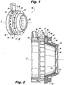
- Fig. 1 a partial view of an exemplary embodiment of a nozzle in accordance with the disclosure is shown in Fig. 1 and is designated generally by reference character 100.
- Other embodiments of nozzles in accordance with the disclosure, or aspects thereof, are provided in Figs. 2-6B , as will be described.
- the systems and methods described herein provide for radial swirl nozzles with reduced emissions and improved temperature uniformity over traditional radial swirl nozzles.
- a nozzle 100 includes a nozzle body 102 defining a longitudinal axis A.
- Nozzle body 102 includes a fuel circuit 106 radially outboard from an air passage 104 with respect to longitudinal axis A.
- Fuel circuit 106 is defined between a fuel circuit inner wall 115 and a fuel circuit outer wall 116. It is contemplated that inner and outer fuel circuit walls 115 and 116, respectively, can be made from a metallic material. A portion of fuel circuit outer wall 116 is radially outboard from fuel circuit inner wall 115 with respect to longitudinal axis A. A portion of both the fuel circuit inner wall 115 and outer wall 116 are conically shaped and converge toward longitudinal axis A.
- Fuel circuit annular outlet 110 is proximate to the outlet of air passage 104.
- air passage 104 is defined between a backing plate 124 and a jacket 134 downstream from backing plate 124.
- backing plate 124 and jacket 134 can be made from thin metallic materials and/or a thicker ceramic material, such as a ceramic-matrix composite (CMC) material, e.g. jacket 134 can be an insulation jacket.
- Air passage 104 includes a radial swirler 107 at an annular inlet 126. Radial swirler 107 has radial swirl vanes 128 circumferentially spaced apart from one another about annular inlet 126 to induce swirl into air entering air passage 104. Large swirl offset and pure radial entry produces very high swirl and high radial pressure gradient at fuel outlet 110.
- an outer air passage 130 is defined radially outboard of fuel circuit 106 with respect to longitudinal axis A. Outer air passage 130 provides non-swirled air. Outer air passage 130 is between a jacket 136 and an outer air passage wall 131. It is contemplated jacket 136 and an outer air passage wall 131 can be constructed using a thin metallic material and/or thicker ceramic material, e.g. a CMC material.
- jacket 136 can be a metallic shell and not provide any insulation and/or it can be a ceramic material and be an insulation jacket to insulate fuel circuit 106.
- Insulation jackets can be made from a ceramic or a ceramic composite material, both of which tend to reduce thermal growth mismatch.
- Metallic shells can be designed to mitigate thermal growth effects, e.g. by using slits, multiple pieces, growth gaps etc.
- air passage 104 e.g. the radial swirler
- air passage 130 can contribute 40% to 50% of total air
- outer air passage 130 contributes 50% to 60% of the flow.
- inner air passage 104 is described as a swirling air passage
- outer air passage 130 is described as a non-swirling air passage, those skilled in the art will readily appreciate that this can be reversed, or both can be counter-swirled, or the like, as needed to provide a shear layer of air for atomization of the fuel exiting fuel circuit 106.
- outer air passage 130 is a converging non-swirling outer air passage 130.
- An annular outlet 132 of outer air passage 130 is proximate to a fuel circuit annular outlet 110.
- Fuel circuit 106 extends from a fuel circuit inlet 108, shown in Fig. 4 , to a fuel circuit annular outlet 110.
- Fuel circuit 106 includes a plurality of helical passages 112 to add resistance to fuel flow before exit, thereby mitigating gravitational effects at low fuel flow rates.
- Traditional fuel distributors tend to drool, e.g. fuel tends to pool at one end, when exposed to similar low flow rates.
- Starting points for helical passages 112 are spaced apart circumferentially.
- the axial distance between passages ranges from 0.030 inches (0.762 mm) to 0.100 inches (2.54 mm). Those skilled in the art will readily appreciate that this distance depends partly on the width of each individual helical passage 112, which can range from between 0.025 inches (.635 mm) to 0.05 inches (1.27 mm).
- the high co-swirling core air from air passage 104 is used to distribute swirling fuel from fuel circuit outlet 110 before mixing with unswirled air from outer air passage 130.
- Converging outer air from outer air passage 130 and diverging inner flow from air passage 104 squeeze the fuel film at an exit 117 of nozzle 100.
- T4 temperature level for modern engines ranges from 2500 to 3500 °F (1371 to 1926 °C).
- the hot temperatures at the nozzle outlet 117 assist in stabilizing reactions downstream in the thin mixing layer.
- the converging layer of unswirled air exiting from outlet air passage 130 is thinner than the diverging layer of swirling air exiting from inner air passage 104.
- the fuel film exiting fuel circuit outlet 110 travels a very short distance to reach outlet 132 of outer air passage 130. Swirling air from air passage 104 continues to squeeze the fuel film downstream into the unswirled converging air layer from outer air passage 130 for an axial distance measured from nozzle outlet 117 of approximately one-half of the diameter of nozzle 100.
- the thin layer of unswirled converging air and the thin fuel film exiting from fuel circuit 106 lead to very rapid mixing of hot reacted gases, fuel and fresh air. Those skilled in the art will readily appreciate that this is different from a premixer since a hot flame zone exists.
- each helical passage 112 of fuel circuit 106 opens tangentially with respect to fuel circuit annular outlet 110 into an outlet 114 of air passage 104.
- Fuel flow exiting fuel circuit 106 exits from outlet 110 at an extremely large tangential angle, for example, the angle can range from 75 to 88 degrees.
- the angle can vary depending on the number of helical passages 112.
- the radial pressure gradient resulting therefrom helps to reduce film thickness at annular outlet 110.
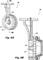
- Each helical passage 112 intersects a single cross-sectional plane taken along longitudinal axis A, for example the cross-sections shown in Figs. 2 and 3 .
- Helical passages 112 intersect each cross-sectional plane taken along longitudinal axis A. Each of helical passages 112 complete at least one 360 degree pass around fuel circuit 106. Helical passages 112 are defined by helical threads 113 in a fuel circuit outer wall 116.
- fuel circuit inlet 108 includes a plurality of circumferentially spaced apart openings 118 in fluid communication with a fuel manifold 120.
- fuel manifold 120 is shown integrally formed with backing plate 124, it can be formed independent of backing plate 124.
- a plurality of cylindrical tubes 122 are defined through air passage 104.
- Each tube 122 connects a respective opening 118 to fuel manifold 122.
- Tubes 122 can be metallic transfer tubes. It is also contemplated that in place of some of tubes 122, fasteners can also be used. Vanes, described above, can be hollow and/or ceramic, and are used to insulate tubes 122 as they pass through air passage.
- nozzle 200 is similar to nozzle 100.
- Nozzle 200 includes a low-flow fuel nozzle 201 integrated into a backing plate 224 of nozzle body 202 upstream from air passage 204. Those skilled in the art will readily appreciate that this will assist with fuel staging, if required.
- nozzles 100 and 200 are easily manufactured radial swirlers that are lightweight.
- Nozzles 100 and 200 can be additively manufactured, for example using direct metal laser sintering, or the like.
- components of nozzle body 102 and 202 can be appropriately spaced to permit thermal expansion and contraction.
- annular fuel outlet 110 with very limited exposure to the hot surface of air passage 104 outlet 114, eliminates backflow and flashback possibility that tends to exist if fuel is introduced too early into core.
Landscapes
- Engineering & Computer Science (AREA)
- Chemical & Material Sciences (AREA)
- Combustion & Propulsion (AREA)
- Mechanical Engineering (AREA)
- General Engineering & Computer Science (AREA)
- Spray-Type Burners (AREA)
- Fuel-Injection Apparatus (AREA)
Applications Claiming Priority (1)
| Application Number | Priority Date | Filing Date | Title |
|---|---|---|---|
| US14/674,580 US9897321B2 (en) | 2015-03-31 | 2015-03-31 | Fuel nozzles |
Publications (2)
| Publication Number | Publication Date |
|---|---|
| EP3076082A1 true EP3076082A1 (fr) | 2016-10-05 |
| EP3076082B1 EP3076082B1 (fr) | 2018-07-25 |
Family
ID=55661285
Family Applications (1)
| Application Number | Title | Priority Date | Filing Date |
|---|---|---|---|
| EP16163366.4A Active EP3076082B1 (fr) | 2015-03-31 | 2016-03-31 | Buses de combustible |
Country Status (2)
| Country | Link |
|---|---|
| US (1) | US9897321B2 (fr) |
| EP (1) | EP3076082B1 (fr) |
Cited By (2)
| Publication number | Priority date | Publication date | Assignee | Title |
|---|---|---|---|---|
| EP3382280A1 (fr) * | 2017-03-31 | 2018-10-03 | Delavan, Inc. | Injecteurs de carburant pour réseaux multipoints |
| EP3499127A1 (fr) * | 2017-12-15 | 2019-06-19 | Delavan, Inc. | Distributeur de combustible hélicoïdal conique |
Families Citing this family (15)
| Publication number | Priority date | Publication date | Assignee | Title |
|---|---|---|---|---|
| US8375548B2 (en) * | 2009-10-07 | 2013-02-19 | Pratt & Whitney Canada Corp. | Fuel nozzle and method of repair |
| US9188063B2 (en) | 2011-11-03 | 2015-11-17 | Delavan Inc. | Injectors for multipoint injection |
| US10385809B2 (en) | 2015-03-31 | 2019-08-20 | Delavan Inc. | Fuel nozzles |
| US10196983B2 (en) * | 2015-11-04 | 2019-02-05 | General Electric Company | Fuel nozzle for gas turbine engine |
| US10634355B2 (en) * | 2016-12-16 | 2020-04-28 | Delavan Inc. | Dual fuel radial flow nozzles |
| US10344981B2 (en) * | 2016-12-16 | 2019-07-09 | Delavan Inc. | Staged dual fuel radial nozzle with radial liquid fuel distributor |
| US10527286B2 (en) * | 2016-12-16 | 2020-01-07 | Delavan, Inc | Staged radial air swirler with radial liquid fuel distributor |
| GB2565761A (en) * | 2017-07-28 | 2019-02-27 | Tunley Enginering | Combustion engine fuel mixture system |
| US11143406B2 (en) * | 2018-04-10 | 2021-10-12 | Delavan Inc. | Fuel injectors having air sealing structures |
| US11174792B2 (en) | 2019-05-21 | 2021-11-16 | General Electric Company | System and method for high frequency acoustic dampers with baffles |
| US11156164B2 (en) | 2019-05-21 | 2021-10-26 | General Electric Company | System and method for high frequency accoustic dampers with caps |
| GB201907834D0 (en) * | 2019-06-03 | 2019-07-17 | Rolls Royce Plc | A fuel sparay nozzle arrangement |
| US11378275B2 (en) * | 2019-12-06 | 2022-07-05 | Raytheon Technologies Corporation | High shear swirler with recessed fuel filmer for a gas turbine engine |
| EP3904768B1 (fr) * | 2020-04-28 | 2024-04-17 | Collins Engine Nozzles, Inc. | Buse de fluides |
| JP2022150960A (ja) * | 2021-03-26 | 2022-10-07 | 本田技研工業株式会社 | ガスタービン用燃料ノズル装置 |
Citations (5)
| Publication number | Priority date | Publication date | Assignee | Title |
|---|---|---|---|---|
| EP1526332A2 (fr) * | 2003-10-20 | 2005-04-27 | Rolls-Royce Deutschland Ltd & Co KG | Injecteur de combustible |
| WO2005061964A1 (fr) * | 2003-12-24 | 2005-07-07 | Pratt & Whitney Canada Corp. | Distributeur de combustible a canal helicoidal et procede |
| US20090224080A1 (en) * | 2008-03-04 | 2009-09-10 | Delavan Inc | Pure Air Blast Fuel Injector |
| EP2589866A2 (fr) * | 2011-11-03 | 2013-05-08 | Delavan Inc. | Injecteurs à air comprimé pour injection multipoint et procédés d'assemblage |
| US20140090382A1 (en) * | 2011-05-17 | 2014-04-03 | Snecma | Annular combustion chamber for a turbine engine |
Family Cites Families (57)
| Publication number | Priority date | Publication date | Assignee | Title |
|---|---|---|---|---|
| US1875457A (en) | 1932-09-06 | Torkild valdemar hemmingsen | ||
| BE488386A (fr) | ||||
| US2607193A (en) | 1947-10-25 | 1952-08-19 | Curtiss Wright Corp | Annular combustion chamber with multiple notched fuel nozzles |
| US3680793A (en) | 1970-11-09 | 1972-08-01 | Delavan Manufacturing Co | Eccentric spiral swirl chamber nozzle |
| US3912164A (en) | 1971-01-11 | 1975-10-14 | Parker Hannifin Corp | Method of liquid fuel injection, and to air blast atomizers |
| GB1421399A (en) | 1972-11-13 | 1976-01-14 | Snecma | Fuel injectors |
| US3980233A (en) | 1974-10-07 | 1976-09-14 | Parker-Hannifin Corporation | Air-atomizing fuel nozzle |
| JPS57187531A (en) | 1981-05-12 | 1982-11-18 | Hitachi Ltd | Low nox gas turbine burner |
| US4600151A (en) | 1982-11-23 | 1986-07-15 | Ex-Cell-O Corporation | Fuel injector assembly with water or auxiliary fuel capability |
| US4653278A (en) | 1985-08-23 | 1987-03-31 | General Electric Company | Gas turbine engine carburetor |
| EP0604741B1 (fr) | 1987-12-11 | 1998-05-13 | Deutsches Zentrum für Luft- und Raumfahrt e.V. | Buse à tourbillonnement pour pulvériser un liquide |
| US5409169A (en) | 1991-06-19 | 1995-04-25 | Hitachi America, Ltd. | Air-assist fuel injection system |
| US5361586A (en) | 1993-04-15 | 1994-11-08 | Westinghouse Electric Corporation | Gas turbine ultra low NOx combustor |
| FR2721694B1 (fr) | 1994-06-22 | 1996-07-19 | Snecma | Refroidissement de l'injecteur de décollage d'une chambre de combustion à deux têtes. |
| US5860600A (en) | 1996-10-01 | 1999-01-19 | Todd Combustion | Atomizer (low opacity) |
| DE19645961A1 (de) | 1996-11-07 | 1998-05-14 | Bmw Rolls Royce Gmbh | Kraftstoffeinspritzvorrichtung für eine Gasturbinen-Brennkammer mit einer flüssigkeitsgekühlten Einspritzdüse |
| GB2319078B (en) | 1996-11-08 | 1999-11-03 | Europ Gas Turbines Ltd | Combustor arrangement |
| US6082113A (en) | 1998-05-22 | 2000-07-04 | Pratt & Whitney Canada Corp. | Gas turbine fuel injector |
| US6092363A (en) | 1998-06-19 | 2000-07-25 | Siemens Westinghouse Power Corporation | Low Nox combustor having dual fuel injection system |
| US6533954B2 (en) | 2000-02-28 | 2003-03-18 | Parker-Hannifin Corporation | Integrated fluid injection air mixing system |
| US6363726B1 (en) | 2000-09-29 | 2002-04-02 | General Electric Company | Mixer having multiple swirlers |
| FR2817017B1 (fr) | 2000-11-21 | 2003-03-07 | Snecma Moteurs | Refroidissement integral des injecteurs de decollage d'une chambre de combustion a deux tetes |
| US6688534B2 (en) | 2001-03-07 | 2004-02-10 | Delavan Inc | Air assist fuel nozzle |
| US6622488B2 (en) | 2001-03-21 | 2003-09-23 | Parker-Hannifin Corporation | Pure airblast nozzle |
| US6755024B1 (en) | 2001-08-23 | 2004-06-29 | Delavan Inc. | Multiplex injector |
| US6854670B2 (en) | 2002-05-17 | 2005-02-15 | Keihin Corporation | Fuel injection valve |
| US7028484B2 (en) | 2002-08-30 | 2006-04-18 | Pratt & Whitney Canada Corp. | Nested channel ducts for nozzle construction and the like |
| US6962055B2 (en) | 2002-09-27 | 2005-11-08 | United Technologies Corporation | Multi-point staging strategy for low emission and stable combustion |
| US6863228B2 (en) | 2002-09-30 | 2005-03-08 | Delavan Inc. | Discrete jet atomizer |
| JP4065947B2 (ja) | 2003-08-05 | 2008-03-26 | 独立行政法人 宇宙航空研究開発機構 | ガスタービン燃焼器用燃料・空気プレミキサー |
| JP2005061715A (ja) | 2003-08-13 | 2005-03-10 | Ishikawajima Harima Heavy Ind Co Ltd | 希薄予蒸発予混合燃焼器 |
| US7654088B2 (en) | 2004-02-27 | 2010-02-02 | Pratt & Whitney Canada Corp. | Dual conduit fuel manifold for gas turbine engine |
| US8348180B2 (en) | 2004-06-09 | 2013-01-08 | Delavan Inc | Conical swirler for fuel injectors and combustor domes and methods of manufacturing the same |
| US7533531B2 (en) | 2005-04-01 | 2009-05-19 | Pratt & Whitney Canada Corp. | Internal fuel manifold with airblast nozzles |
| US7878000B2 (en) | 2005-12-20 | 2011-02-01 | General Electric Company | Pilot fuel injector for mixer assembly of a high pressure gas turbine engine |
| FR2896030B1 (fr) * | 2006-01-09 | 2008-04-18 | Snecma Sa | Refroidissement d'un dispositif d'injection multimode pour chambre de combustion, notamment d'un turboreacteur |
| US7520134B2 (en) | 2006-09-29 | 2009-04-21 | General Electric Company | Methods and apparatus for injecting fluids into a turbine engine |
| GB0625016D0 (en) | 2006-12-15 | 2007-01-24 | Rolls Royce Plc | Fuel injector |
| FR2911667B1 (fr) | 2007-01-23 | 2009-10-02 | Snecma Sa | Systeme d'injection de carburant a double injecteur. |
| US8015796B2 (en) | 2007-06-05 | 2011-09-13 | United Technologies Corporation | Gas turbine engine with dual fans driven about a central core axis |
| FR2919898B1 (fr) | 2007-08-10 | 2014-08-22 | Snecma | Injecteur multipoint pour turbomachine |
| US7861528B2 (en) | 2007-08-21 | 2011-01-04 | General Electric Company | Fuel nozzle and diffusion tip therefor |
| US20090111063A1 (en) | 2007-10-29 | 2009-04-30 | General Electric Company | Lean premixed, radial inflow, multi-annular staged nozzle, can-annular, dual-fuel combustor |
| US7926178B2 (en) | 2007-11-30 | 2011-04-19 | Delavan Inc | Method of fuel nozzle construction |
| US20090255258A1 (en) | 2008-04-11 | 2009-10-15 | Delavan Inc | Pre-filming air-blast fuel injector having a reduced hydraulic spray angle |
| US8806871B2 (en) | 2008-04-11 | 2014-08-19 | General Electric Company | Fuel nozzle |
| US8096135B2 (en) | 2008-05-06 | 2012-01-17 | Dela Van Inc | Pure air blast fuel injector |
| US8347630B2 (en) | 2008-09-03 | 2013-01-08 | United Technologies Corp | Air-blast fuel-injector with shield-cone upstream of fuel orifices |
| GB0820560D0 (en) | 2008-11-11 | 2008-12-17 | Rolls Royce Plc | Fuel injector |
| US8313046B2 (en) | 2009-08-04 | 2012-11-20 | Delavan Inc | Multi-point injector ring |
| US8663348B2 (en) | 2010-08-11 | 2014-03-04 | General Electric Company | Apparatus for removing heat from injection devices and method of assembling same |
| US10317081B2 (en) | 2011-01-26 | 2019-06-11 | United Technologies Corporation | Fuel injector assembly |
| US9383097B2 (en) | 2011-03-10 | 2016-07-05 | Rolls-Royce Plc | Systems and method for cooling a staged airblast fuel injector |
| US8925325B2 (en) * | 2011-03-18 | 2015-01-06 | Delavan Inc. | Recirculating product injection nozzle |
| US9441836B2 (en) | 2012-07-10 | 2016-09-13 | United Technologies Corporation | Fuel-air pre-mixer with prefilmer |
| US10161633B2 (en) | 2013-03-04 | 2018-12-25 | Delavan Inc. | Air swirlers |
| US9592480B2 (en) | 2013-05-13 | 2017-03-14 | Solar Turbines Incorporated | Inner premix tube air wipe |
-
2015
- 2015-03-31 US US14/674,580 patent/US9897321B2/en active Active
-
2016
- 2016-03-31 EP EP16163366.4A patent/EP3076082B1/fr active Active
Patent Citations (5)
| Publication number | Priority date | Publication date | Assignee | Title |
|---|---|---|---|---|
| EP1526332A2 (fr) * | 2003-10-20 | 2005-04-27 | Rolls-Royce Deutschland Ltd & Co KG | Injecteur de combustible |
| WO2005061964A1 (fr) * | 2003-12-24 | 2005-07-07 | Pratt & Whitney Canada Corp. | Distributeur de combustible a canal helicoidal et procede |
| US20090224080A1 (en) * | 2008-03-04 | 2009-09-10 | Delavan Inc | Pure Air Blast Fuel Injector |
| US20140090382A1 (en) * | 2011-05-17 | 2014-04-03 | Snecma | Annular combustion chamber for a turbine engine |
| EP2589866A2 (fr) * | 2011-11-03 | 2013-05-08 | Delavan Inc. | Injecteurs à air comprimé pour injection multipoint et procédés d'assemblage |
Cited By (4)
| Publication number | Priority date | Publication date | Assignee | Title |
|---|---|---|---|---|
| EP3382280A1 (fr) * | 2017-03-31 | 2018-10-03 | Delavan, Inc. | Injecteurs de carburant pour réseaux multipoints |
| US10859269B2 (en) | 2017-03-31 | 2020-12-08 | Delavan Inc. | Fuel injectors for multipoint arrays |
| US11906167B2 (en) | 2017-03-31 | 2024-02-20 | Collins Engine Nozzles, Inc. | Fuel injectors for multipoint arrays |
| EP3499127A1 (fr) * | 2017-12-15 | 2019-06-19 | Delavan, Inc. | Distributeur de combustible hélicoïdal conique |
Also Published As
| Publication number | Publication date |
|---|---|
| EP3076082B1 (fr) | 2018-07-25 |
| US9897321B2 (en) | 2018-02-20 |
| US20160290649A1 (en) | 2016-10-06 |
Similar Documents
| Publication | Publication Date | Title |
|---|---|---|
| EP3076082B1 (fr) | Buses de combustible | |
| US11111888B2 (en) | Fuel nozzles | |
| US11628455B2 (en) | Atomizers | |
| US10208956B2 (en) | Combustor for gas turbine engine | |
| US20190101291A1 (en) | Air swirlers | |
| US10788209B2 (en) | Combustor for gas turbine engine | |
| US9488108B2 (en) | Radial vane inner air swirlers | |
| US10788214B2 (en) | Fuel injectors for turbomachines having inner air swirling | |
| GB1575410A (en) | Combustion apparatus for use in gas turbine engines | |
| CN108731029B (zh) | 喷气燃料喷嘴 | |
| US11680527B2 (en) | Nozzles with internal manifolding | |
| EP3336432B1 (fr) | Appareil de tourbillonnement d'air radial étagé avec distributeur de carburant liquide radial | |
| CA2845164C (fr) | Chambre de combustion pour turbine a gaz | |
| US10724741B2 (en) | Combustors and methods of assembling the same |
Legal Events
| Date | Code | Title | Description |
|---|---|---|---|
| PUAI | Public reference made under article 153(3) epc to a published international application that has entered the european phase |
Free format text: ORIGINAL CODE: 0009012 |
|
| AK | Designated contracting states |
Kind code of ref document: A1 Designated state(s): AL AT BE BG CH CY CZ DE DK EE ES FI FR GB GR HR HU IE IS IT LI LT LU LV MC MK MT NL NO PL PT RO RS SE SI SK SM TR |
|
| AX | Request for extension of the european patent |
Extension state: BA ME |
|
| STAA | Information on the status of an ep patent application or granted ep patent |
Free format text: STATUS: REQUEST FOR EXAMINATION WAS MADE |
|
| 17P | Request for examination filed |
Effective date: 20170405 |
|
| RBV | Designated contracting states (corrected) |
Designated state(s): AL AT BE BG CH CY CZ DE DK EE ES FI FR GB GR HR HU IE IS IT LI LT LU LV MC MK MT NL NO PL PT RO RS SE SI SK SM TR |
|
| GRAJ | Information related to disapproval of communication of intention to grant by the applicant or resumption of examination proceedings by the epo deleted |
Free format text: ORIGINAL CODE: EPIDOSDIGR1 |
|
| GRAP | Despatch of communication of intention to grant a patent |
Free format text: ORIGINAL CODE: EPIDOSNIGR1 |
|
| RIC1 | Information provided on ipc code assigned before grant |
Ipc: F23R 3/28 20060101ALI20171215BHEP Ipc: F23R 3/34 20060101ALI20171215BHEP Ipc: F23D 11/10 20060101ALI20171215BHEP Ipc: F23R 3/14 20060101AFI20171215BHEP Ipc: F23D 11/38 20060101ALI20171215BHEP |
|
| GRAP | Despatch of communication of intention to grant a patent |
Free format text: ORIGINAL CODE: EPIDOSNIGR1 |
|
| STAA | Information on the status of an ep patent application or granted ep patent |
Free format text: STATUS: GRANT OF PATENT IS INTENDED |
|
| INTG | Intention to grant announced |
Effective date: 20180126 |
|
| GRAS | Grant fee paid |
Free format text: ORIGINAL CODE: EPIDOSNIGR3 |
|
| GRAA | (expected) grant |
Free format text: ORIGINAL CODE: 0009210 |
|
| STAA | Information on the status of an ep patent application or granted ep patent |
Free format text: STATUS: THE PATENT HAS BEEN GRANTED |
|
| AK | Designated contracting states |
Kind code of ref document: B1 Designated state(s): AL AT BE BG CH CY CZ DE DK EE ES FI FR GB GR HR HU IE IS IT LI LT LU LV MC MK MT NL NO PL PT RO RS SE SI SK SM TR |
|
| REG | Reference to a national code |
Ref country code: GB Ref legal event code: FG4D |
|
| REG | Reference to a national code |
Ref country code: CH Ref legal event code: EP |
|
| REG | Reference to a national code |
Ref country code: AT Ref legal event code: REF Ref document number: 1022183 Country of ref document: AT Kind code of ref document: T Effective date: 20180815 |
|
| REG | Reference to a national code |
Ref country code: IE Ref legal event code: FG4D |
|
| REG | Reference to a national code |
Ref country code: DE Ref legal event code: R096 Ref document number: 602016004200 Country of ref document: DE |
|
| REG | Reference to a national code |
Ref country code: NL Ref legal event code: MP Effective date: 20180725 |
|
| REG | Reference to a national code |
Ref country code: LT Ref legal event code: MG4D |
|
| PG25 | Lapsed in a contracting state [announced via postgrant information from national office to epo] |
Ref country code: NL Free format text: LAPSE BECAUSE OF FAILURE TO SUBMIT A TRANSLATION OF THE DESCRIPTION OR TO PAY THE FEE WITHIN THE PRESCRIBED TIME-LIMIT Effective date: 20180725 |
|
| REG | Reference to a national code |
Ref country code: AT Ref legal event code: MK05 Ref document number: 1022183 Country of ref document: AT Kind code of ref document: T Effective date: 20180725 |
|
| PG25 | Lapsed in a contracting state [announced via postgrant information from national office to epo] |
Ref country code: BG Free format text: LAPSE BECAUSE OF FAILURE TO SUBMIT A TRANSLATION OF THE DESCRIPTION OR TO PAY THE FEE WITHIN THE PRESCRIBED TIME-LIMIT Effective date: 20181025 Ref country code: LT Free format text: LAPSE BECAUSE OF FAILURE TO SUBMIT A TRANSLATION OF THE DESCRIPTION OR TO PAY THE FEE WITHIN THE PRESCRIBED TIME-LIMIT Effective date: 20180725 Ref country code: PL Free format text: LAPSE BECAUSE OF FAILURE TO SUBMIT A TRANSLATION OF THE DESCRIPTION OR TO PAY THE FEE WITHIN THE PRESCRIBED TIME-LIMIT Effective date: 20180725 Ref country code: SE Free format text: LAPSE BECAUSE OF FAILURE TO SUBMIT A TRANSLATION OF THE DESCRIPTION OR TO PAY THE FEE WITHIN THE PRESCRIBED TIME-LIMIT Effective date: 20180725 Ref country code: NO Free format text: LAPSE BECAUSE OF FAILURE TO SUBMIT A TRANSLATION OF THE DESCRIPTION OR TO PAY THE FEE WITHIN THE PRESCRIBED TIME-LIMIT Effective date: 20181025 Ref country code: FI Free format text: LAPSE BECAUSE OF FAILURE TO SUBMIT A TRANSLATION OF THE DESCRIPTION OR TO PAY THE FEE WITHIN THE PRESCRIBED TIME-LIMIT Effective date: 20180725 Ref country code: AT Free format text: LAPSE BECAUSE OF FAILURE TO SUBMIT A TRANSLATION OF THE DESCRIPTION OR TO PAY THE FEE WITHIN THE PRESCRIBED TIME-LIMIT Effective date: 20180725 Ref country code: RS Free format text: LAPSE BECAUSE OF FAILURE TO SUBMIT A TRANSLATION OF THE DESCRIPTION OR TO PAY THE FEE WITHIN THE PRESCRIBED TIME-LIMIT Effective date: 20180725 Ref country code: IS Free format text: LAPSE BECAUSE OF FAILURE TO SUBMIT A TRANSLATION OF THE DESCRIPTION OR TO PAY THE FEE WITHIN THE PRESCRIBED TIME-LIMIT Effective date: 20181125 Ref country code: GR Free format text: LAPSE BECAUSE OF FAILURE TO SUBMIT A TRANSLATION OF THE DESCRIPTION OR TO PAY THE FEE WITHIN THE PRESCRIBED TIME-LIMIT Effective date: 20181026 |
|
| PG25 | Lapsed in a contracting state [announced via postgrant information from national office to epo] |
Ref country code: HR Free format text: LAPSE BECAUSE OF FAILURE TO SUBMIT A TRANSLATION OF THE DESCRIPTION OR TO PAY THE FEE WITHIN THE PRESCRIBED TIME-LIMIT Effective date: 20180725 Ref country code: LV Free format text: LAPSE BECAUSE OF FAILURE TO SUBMIT A TRANSLATION OF THE DESCRIPTION OR TO PAY THE FEE WITHIN THE PRESCRIBED TIME-LIMIT Effective date: 20180725 Ref country code: AL Free format text: LAPSE BECAUSE OF FAILURE TO SUBMIT A TRANSLATION OF THE DESCRIPTION OR TO PAY THE FEE WITHIN THE PRESCRIBED TIME-LIMIT Effective date: 20180725 |
|
| REG | Reference to a national code |
Ref country code: DE Ref legal event code: R097 Ref document number: 602016004200 Country of ref document: DE |
|
| PG25 | Lapsed in a contracting state [announced via postgrant information from national office to epo] |
Ref country code: EE Free format text: LAPSE BECAUSE OF FAILURE TO SUBMIT A TRANSLATION OF THE DESCRIPTION OR TO PAY THE FEE WITHIN THE PRESCRIBED TIME-LIMIT Effective date: 20180725 Ref country code: IT Free format text: LAPSE BECAUSE OF FAILURE TO SUBMIT A TRANSLATION OF THE DESCRIPTION OR TO PAY THE FEE WITHIN THE PRESCRIBED TIME-LIMIT Effective date: 20180725 Ref country code: CZ Free format text: LAPSE BECAUSE OF FAILURE TO SUBMIT A TRANSLATION OF THE DESCRIPTION OR TO PAY THE FEE WITHIN THE PRESCRIBED TIME-LIMIT Effective date: 20180725 Ref country code: RO Free format text: LAPSE BECAUSE OF FAILURE TO SUBMIT A TRANSLATION OF THE DESCRIPTION OR TO PAY THE FEE WITHIN THE PRESCRIBED TIME-LIMIT Effective date: 20180725 Ref country code: ES Free format text: LAPSE BECAUSE OF FAILURE TO SUBMIT A TRANSLATION OF THE DESCRIPTION OR TO PAY THE FEE WITHIN THE PRESCRIBED TIME-LIMIT Effective date: 20180725 |
|
| PG25 | Lapsed in a contracting state [announced via postgrant information from national office to epo] |
Ref country code: SK Free format text: LAPSE BECAUSE OF FAILURE TO SUBMIT A TRANSLATION OF THE DESCRIPTION OR TO PAY THE FEE WITHIN THE PRESCRIBED TIME-LIMIT Effective date: 20180725 Ref country code: DK Free format text: LAPSE BECAUSE OF FAILURE TO SUBMIT A TRANSLATION OF THE DESCRIPTION OR TO PAY THE FEE WITHIN THE PRESCRIBED TIME-LIMIT Effective date: 20180725 Ref country code: SM Free format text: LAPSE BECAUSE OF FAILURE TO SUBMIT A TRANSLATION OF THE DESCRIPTION OR TO PAY THE FEE WITHIN THE PRESCRIBED TIME-LIMIT Effective date: 20180725 |
|
| PLBE | No opposition filed within time limit |
Free format text: ORIGINAL CODE: 0009261 |
|
| STAA | Information on the status of an ep patent application or granted ep patent |
Free format text: STATUS: NO OPPOSITION FILED WITHIN TIME LIMIT |
|
| 26N | No opposition filed |
Effective date: 20190426 |
|
| PG25 | Lapsed in a contracting state [announced via postgrant information from national office to epo] |
Ref country code: SI Free format text: LAPSE BECAUSE OF FAILURE TO SUBMIT A TRANSLATION OF THE DESCRIPTION OR TO PAY THE FEE WITHIN THE PRESCRIBED TIME-LIMIT Effective date: 20180725 |
|
| PG25 | Lapsed in a contracting state [announced via postgrant information from national office to epo] |
Ref country code: MC Free format text: LAPSE BECAUSE OF FAILURE TO SUBMIT A TRANSLATION OF THE DESCRIPTION OR TO PAY THE FEE WITHIN THE PRESCRIBED TIME-LIMIT Effective date: 20180725 |
|
| REG | Reference to a national code |
Ref country code: CH Ref legal event code: PL |
|
| PG25 | Lapsed in a contracting state [announced via postgrant information from national office to epo] |
Ref country code: LU Free format text: LAPSE BECAUSE OF NON-PAYMENT OF DUE FEES Effective date: 20190331 |
|
| REG | Reference to a national code |
Ref country code: BE Ref legal event code: MM Effective date: 20190331 |
|
| PG25 | Lapsed in a contracting state [announced via postgrant information from national office to epo] |
Ref country code: LI Free format text: LAPSE BECAUSE OF NON-PAYMENT OF DUE FEES Effective date: 20190331 Ref country code: CH Free format text: LAPSE BECAUSE OF NON-PAYMENT OF DUE FEES Effective date: 20190331 Ref country code: IE Free format text: LAPSE BECAUSE OF NON-PAYMENT OF DUE FEES Effective date: 20190331 |
|
| PG25 | Lapsed in a contracting state [announced via postgrant information from national office to epo] |
Ref country code: BE Free format text: LAPSE BECAUSE OF NON-PAYMENT OF DUE FEES Effective date: 20190331 |
|
| PG25 | Lapsed in a contracting state [announced via postgrant information from national office to epo] |
Ref country code: TR Free format text: LAPSE BECAUSE OF FAILURE TO SUBMIT A TRANSLATION OF THE DESCRIPTION OR TO PAY THE FEE WITHIN THE PRESCRIBED TIME-LIMIT Effective date: 20180725 |
|
| PG25 | Lapsed in a contracting state [announced via postgrant information from national office to epo] |
Ref country code: MT Free format text: LAPSE BECAUSE OF NON-PAYMENT OF DUE FEES Effective date: 20190331 Ref country code: PT Free format text: LAPSE BECAUSE OF FAILURE TO SUBMIT A TRANSLATION OF THE DESCRIPTION OR TO PAY THE FEE WITHIN THE PRESCRIBED TIME-LIMIT Effective date: 20181125 |
|
| PG25 | Lapsed in a contracting state [announced via postgrant information from national office to epo] |
Ref country code: CY Free format text: LAPSE BECAUSE OF FAILURE TO SUBMIT A TRANSLATION OF THE DESCRIPTION OR TO PAY THE FEE WITHIN THE PRESCRIBED TIME-LIMIT Effective date: 20180725 |
|
| PG25 | Lapsed in a contracting state [announced via postgrant information from national office to epo] |
Ref country code: HU Free format text: LAPSE BECAUSE OF FAILURE TO SUBMIT A TRANSLATION OF THE DESCRIPTION OR TO PAY THE FEE WITHIN THE PRESCRIBED TIME-LIMIT; INVALID AB INITIO Effective date: 20160331 |
|
| PG25 | Lapsed in a contracting state [announced via postgrant information from national office to epo] |
Ref country code: MK Free format text: LAPSE BECAUSE OF FAILURE TO SUBMIT A TRANSLATION OF THE DESCRIPTION OR TO PAY THE FEE WITHIN THE PRESCRIBED TIME-LIMIT Effective date: 20180725 |
|
| P01 | Opt-out of the competence of the unified patent court (upc) registered |
Effective date: 20230530 |
|
| PGFP | Annual fee paid to national office [announced via postgrant information from national office to epo] |
Ref country code: DE Payment date: 20240220 Year of fee payment: 9 Ref country code: GB Payment date: 20240220 Year of fee payment: 9 |
|
| PGFP | Annual fee paid to national office [announced via postgrant information from national office to epo] |
Ref country code: FR Payment date: 20240220 Year of fee payment: 9 |