EP3076034A1 - Track roller bearing - Google Patents
Track roller bearing Download PDFInfo
- Publication number
- EP3076034A1 EP3076034A1 EP16162725.2A EP16162725A EP3076034A1 EP 3076034 A1 EP3076034 A1 EP 3076034A1 EP 16162725 A EP16162725 A EP 16162725A EP 3076034 A1 EP3076034 A1 EP 3076034A1
- Authority
- EP
- European Patent Office
- Prior art keywords
- resin liner
- roller bearing
- circumferential surface
- track roller
- outer ring
- Prior art date
- Legal status (The legal status is an assumption and is not a legal conclusion. Google has not performed a legal analysis and makes no representation as to the accuracy of the status listed.)
- Granted
Links
Images



Classifications
-
- F—MECHANICAL ENGINEERING; LIGHTING; HEATING; WEAPONS; BLASTING
- F16—ENGINEERING ELEMENTS AND UNITS; GENERAL MEASURES FOR PRODUCING AND MAINTAINING EFFECTIVE FUNCTIONING OF MACHINES OR INSTALLATIONS; THERMAL INSULATION IN GENERAL
- F16C—SHAFTS; FLEXIBLE SHAFTS; ELEMENTS OR CRANKSHAFT MECHANISMS; ROTARY BODIES OTHER THAN GEARING ELEMENTS; BEARINGS
- F16C33/00—Parts of bearings; Special methods for making bearings or parts thereof
- F16C33/30—Parts of ball or roller bearings
- F16C33/66—Special parts or details in view of lubrication
- F16C33/6696—Special parts or details in view of lubrication with solids as lubricant, e.g. dry coatings, powder
-
- F—MECHANICAL ENGINEERING; LIGHTING; HEATING; WEAPONS; BLASTING
- F16—ENGINEERING ELEMENTS AND UNITS; GENERAL MEASURES FOR PRODUCING AND MAINTAINING EFFECTIVE FUNCTIONING OF MACHINES OR INSTALLATIONS; THERMAL INSULATION IN GENERAL
- F16C—SHAFTS; FLEXIBLE SHAFTS; ELEMENTS OR CRANKSHAFT MECHANISMS; ROTARY BODIES OTHER THAN GEARING ELEMENTS; BEARINGS
- F16C13/00—Rolls, drums, discs, or the like; Bearings or mountings therefor
- F16C13/006—Guiding rollers, wheels or the like, formed by or on the outer element of a single bearing or bearing unit, e.g. two adjacent bearings, whose ratio of length to diameter is generally less than one
-
- F—MECHANICAL ENGINEERING; LIGHTING; HEATING; WEAPONS; BLASTING
- F16—ENGINEERING ELEMENTS AND UNITS; GENERAL MEASURES FOR PRODUCING AND MAINTAINING EFFECTIVE FUNCTIONING OF MACHINES OR INSTALLATIONS; THERMAL INSULATION IN GENERAL
- F16C—SHAFTS; FLEXIBLE SHAFTS; ELEMENTS OR CRANKSHAFT MECHANISMS; ROTARY BODIES OTHER THAN GEARING ELEMENTS; BEARINGS
- F16C33/00—Parts of bearings; Special methods for making bearings or parts thereof
- F16C33/30—Parts of ball or roller bearings
- F16C33/34—Rollers; Needles
-
- F—MECHANICAL ENGINEERING; LIGHTING; HEATING; WEAPONS; BLASTING
- F16—ENGINEERING ELEMENTS AND UNITS; GENERAL MEASURES FOR PRODUCING AND MAINTAINING EFFECTIVE FUNCTIONING OF MACHINES OR INSTALLATIONS; THERMAL INSULATION IN GENERAL
- F16C—SHAFTS; FLEXIBLE SHAFTS; ELEMENTS OR CRANKSHAFT MECHANISMS; ROTARY BODIES OTHER THAN GEARING ELEMENTS; BEARINGS
- F16C33/00—Parts of bearings; Special methods for making bearings or parts thereof
- F16C33/30—Parts of ball or roller bearings
- F16C33/58—Raceways; Race rings
Definitions
- the present invention relates to track roller bearings whose inner ring and outer ring are combined in a slidably rotatable manner via a resin liner and, in particular, to a track roller bearing suitable for use under high load condition.
- track roller bearings are applied to slats provided in a leading edge portion of the wing and to flaps provided in a trailing edge portion of the wing in such a way that the slats and flaps are extendable and retractable in the front-rear direction (see the patent document 1 mentioned below) .
- This patent document 1 discloses a track roller bearing of such a configuration that the inner ring (inside ring) rotatably supports the outer ring (outside ring) while a self-lubricating resin liner is provided between the inner ring and the outer ring.
- the outer ring contacts the track and rotates to move the track roller bearing along the track.
- the slat and flap are supported by the track roller bearing in a state that the slat and flap are capable of extending and retracting. Because the slat and flap are devices to increase or decrease the lift of the wing, the track roller bearing is subjected to a significantly high load.
- Patent Document 1 Japanese Patent Application Laid-open No. 2009-137574 .
- a sliding surface of the liner may be abraded away, and abrasion powder produced by the abrasion may adhere to the sliding surface. If the abrasion powder from the liner adheres to the sliding surface, the rotational torque for rotating the outer ring increases due to the increase of the outer diameter of the sliding surface resulting in a high rotational resistance of the outer ring. Once this problem happens, the outer ring can no longer rotate smoothly and the outer ring slips instead of rotating. In addition, slips may occur when the outer ring is pressed against the track under high load and is abraded away.
- the present invention is made in view of the above problem, and a primary object thereof is to provide a track roller bearing capable of maintaining its smooth rotation for a long period of time to thereby effectively reduce slips.
- a track roller bearing related to an aspect of the present invention includes:
- the liner sliding surface slides on the opposite surface.
- the resin liner has a smaller sliding area against the opposite surface on the other side than in the case of not forming the non-contact portion.
- any abrasion powder produced by abrading away the resin liner is brought into the non-contact portion to suppress the abrasion powder from adhering to the liner sliding surface. Therefore, an increase of the rotary torque for the track roller bearing is suppressed.
- the non-contact portion of the present invention may be configured in any shape.
- the non-contact portion for example, can be a groove extending in at least one of a circumferential direction of the liner sliding surface (a circumferential direction of the inner and outer rings), an axial direction of the liner sliding surface (an axial direction of the inner and outer rings), and an direction oblique to the axial direction.
- the non-contact portion may be a plurality of recesses formed dispersedly.
- the present invention includes such an aspect that a surface on which the resin liner is formed, is covered with the resin liner in the non-contact portion, the surface being the outer circumferential surface of the inner ring and/or the inner circumferential surface of the outer ring.
- the present invention also includes such an aspect that a surface on which the resin liner is formed, is not covered with the resin liner in the non-contact portion, the surface being the outer circumferential surface of the inner ring and/or the inner circumferential surface of the outer ring, and a surface which defines a bottom of the non-contact portion includes a plane in continuity with in interface between the resin liner and the surface on which the resin liner is formed, or a plane farther from the surface of the resin liner than the interface.
- the present invention also includes such an aspect that the non-contact portion is provided symmetrically with respect to a plan orthogonal to an axial direction of the inner ring and the outer ring.
- a component force acting on the outer ring in the axial direction may be brought about when the inner ring and the outer ring rotate relative to each other.
- the non-contact portion is a single groove extending in an oblique direction to intersect the axial direction, then such component force is brought about.
- a plurality of grooves are formed symmetrically with respect to the plane orthogonal to the axial direction, then the component forces brought about in the axial direction cancel out.
- obstruction of the rotation of the track roller bearing due to deviation, in the axial direction, of the outer ring is suppressed.
- Fig. 1A is a vertical cross-sectional view of a track roller bearing 1 related to one embodiment.
- Fig. 2 is an exploded perspective view of the track roller bearing 1.
- the track roller bearing 1 includes a circular inner ring 10 and a circular outer ring 20 made of a metal such as stainless steel or the like.
- the inner ring 10 and the outer ring 20 are assembled in such a manner as concentric and rotatable relative to each other.
- a fixed shaft which is not depicted, is inserted through a through hole 19 of the inner ring 10 and the inner ring 10 is fixed on the fixed shaft. That is, the inner ring 10 is on the fixed side while the outer ring 20 is used in such a state as assembled to be rotatable relative to the inner ring 10.
- the axial direction refers to the axial directions of the inner ring 10 and the outer ring 20 while the circumferential direction refers to the circumferential directions of the inner ring 10 and the outer ring 20.
- the track roller bearing 1 is mounted, for example, on a movable member which is supported to be movable in front-back direction, in a manner that the axial direction of the track roller bearing 1 is orthogonal to the movement in front or back direction of the movable member, and the track roller bearing 1 is used in a state that the outer circumferential surface 21 of the outer ring 20 is in contact with a track having a guide rail shape.
- the outer ring 20 of the track roller bearing 1 rotates to follow the movement of the movable member while being subjected to the load from the movable member.
- the track roller bearing 1 guides the movement of the movable member.
- the movable member can be the aforementioned slat or flap provided in an airplane wing.
- a flange portion 13 is formed to project outwardly in a radial direction. Further, on the other end of the inner ring 10 in the axial direction (right end of the inner ring 10 in Fig. 1A ), a small diameter portion 14 is formed. A washer 15 is fitted and fixed to the small diameter portion 14.
- the outer ring 20 is rotatably fitted to an outer circumferential surface 11 of the inner ring 10 positioned between the washer 15 and the flange portion 13 , with an intervening resin liner 30.
- the resin liner 30 is formed on the outer circumferential surface 11 of the inner ring 10 and on an inner end face 131 of the flange portion 13. Further, the resin liner 30 is also formed on an inner end face 151 of the washer 15.
- annular projections 23 are formed projecting outwardly in the axial direction.
- the outer ring 20 is rotatably fitted on the outer circumferential surface 11 of the inner ring 10 via the resin liner 30.
- an inner circumferential surface 22 of the outer ring 20 slides on an outer circumferential surface 31 of the resin liner 30.
- the inside of the track roller bearing 1, that is, the interspace defined between the inner ring 10 and the outer ring 20, is sealed up by a pair of seal rings 40 fitted in the both ends of the outer ring 20 in the axial direction.
- One seal ring 40 of the pair of seal rings 40 is fitted between the annular projection 23 of the outer ring 20 and the flange portion 13 of the inner ring 10 in an elastically deformed state, while the other seal ring 40 of the pair of seal rings 40 is fitted between the annular projection 23 of the outer ring 20 and the washer 15 in a elastically deformed state.
- circumferential grooves 232 are formed to retain the seal rings 40 in a removable manner.
- the track roller bearing 1 configured as above is assembled according to such a procedure as to insert the inner ring 10 through a through hole 29 of the outer ring 20 retaining the seal rings 40 in the circumferential grooves 232, and then fit and fix the washer 15 into the small diameter portion 14 of the inner ring 10.
- the resin liner 30 described above is formed by covering the outer circumferential surface 11 of the inner ring 10 with a self-lubricating resin containing polytetrafluoroethylene (PTFE) as a solid lubricant.
- PTFE polytetrafluoroethylene
- examples of the resin which can serve as the primary constituent of the resin liner 30 described above is acrylic resin, epoxy resin, polyether ether ketone (PEEK), or the like. However, the resin is not limited to these materials. It is desirable for the resin liner 30 to be as thick as about 0.2 to 0.3 mm.
- the present invention is characterized by a non-contact portion formed on the outer circumferential surface 31 (liner sliding surface) of the resin liner 30, the non-contact portion being a portion at which the resin liner 30 does not contact the inner circumferential surface 22 (opposite surface) of the outer ring 20.
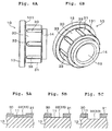
- Specific examples of the non-contact portion can be grooves 32 extending in the circumferential direction as depicted in Figs. 3A and 3B or grooves 33 extending in the axial direction as depicted in Figs. 4A and 4B . Note that, in Figs. 1A and 1B and in Fig. 2 , single groove 32 extending in the circumferential direction is formed in the resin liner 30.
- Three grooves 32 are depicted in Figs. 3A and 3B .
- One of the three grooves 32 is formed at the central part of the resin liner 30 in the axial direction, and one of the two remaining grooves 32 is formed at each end of the resin liner 30 in the axial direction.
- the grooves 32 formed at the both ends of the resin liner 30 in the axial direction are narrower than the groove 32 formed at the central part of the resin liner 30 in the axial direction. Note that, although the narrow groove 32 formed at the side of the small diameter portion 14 is depicted in Figs. 3A and 3B as a portion opened to the end face, this portion becomes a groove having walls on both sides in the axial direction when the washer 15 is fitted into the small diameter portion 14.
- this portion is referred to as the groove 32.
- the number of grooves 32 extending in the circumferential direction is not limited to one as exemplified above. If a plurality of grooves 32 are formed, then it is preferable to arrange the grooves 32 at equal intervals in the axial direction for dispersing the load equally.
- the plurality of grooves 33 which are depicted in Figs 4A and 4B and which extend in the axial direction are formed at equal intervals in the circumferential direction. These grooves 33 are opened to the end face on the side of the small diameter portion 14.
- the groove 33 it is preferable to form at least two of such grooves 33 and, from the point of view of dispersing the load equally, it is preferable to arrange the grooves 33 at equal intervals in the circumferential direction. Further, the grooves 32 and 33 mentioned above may coexist on the outer circumferential surface 31 of the resin liner 30.
- the grooves 32 and 33 by removing the resin liner 30 by means of a cutting operation or the like after forming the resin liner 30 on the entire surface of the outer circumferential surface 11 of the inner ring 10.
- depths of the grooves 32, 33 may be set to be smaller than thickness of the resin liner 30, such that the outer circumferential surface 11 of the inner ring 10 is covered by the resin liner 30 even in the non-contact portion (see Fig. 5A ).
- the resin liner 30 may be entirely removed from a portion in which the groove is formed, such that the outer circumferential surface 11 of the inner ring 10 is not covered by the resin liner 30 in the non-contact portion. In the latter case, it may be possible to adopt two configurations described below.
- bottom surfaces of the grooves 32, 33 are continuous (flush) with the interface between the resin liner 30 and the outer circumferential surface 11 (See, Fig. 5B ) .
- depth of the grooves are set to be larger than the thickness of the resin layer 30 by cutting the surface of the outer circumferential surface 11, that is, in this configuration bottom surfaces of the grooves 32, 33 are farther from the outer circumferential surface 31 than the interface between the resin liner 30 and the outer circumferential surface 11 (see Fig. 5C ) .
- the distances between the bottom surfaces of the grooves 32, 33 and the outer circumferential surface 31 are larger than the distance between the circumferential surface 31 and the interface of the resin liner 30 and the outer circumferential surface 11.
- the depth of the grooves 32 and 33 need not be specified with high precision when making the non-contact portion by cutting process or the like. Therefore, it becomes easier to manufacture the grooves 32 and 33 and, consequently, it becomes easier to manufacture the track roller bearing 1.
- the track roller bearing 1 is mounted to the movable member supported to be movable to extend and retract as described previously in a manner that the axial direction of the track roller bearing 1 is orthogonal to the movement direction of the movable member.
- the track roller bearing 1 is used in a state that the outer circumferential surface 21 of the outer ring 20 is in contact with the track having a guide rail shape.
- the outer ring 20 of the track roller bearing 1 rotates to follow the extension or retraction movement of the movable member, thereby guiding the movement of the movable member.
- the inner circumferential surface 22 of the outer ring 20 slides on the outer circumferential surface 31 of the resin liner 30.
- the outer ring 20 rotates smoothly.
- the grooves 32 (33) are formed as the non-contact portions in the outer circumferential surface 31, that is the liner sliding surface, of the resin liner 30, the non-contact portions being portions in each of which the outer circumferential surface 31 of the resin liner 30 does not contact the inner circumferential surface 22 of the outer ring 20.
- the resin liner 30 has a smaller sliding area against the outer ring 20 than in the case of not forming the non-contact portions.
- the outer circumferential surface 31 of the resin liner 30 is abraded away to produce abrasion powder.
- the rotating outer ring 20 brings the abrasion powder into the grooves 32 (33) to restrain the abrasion powder from adhering to the sliding surface of the outer ring 20 or the resin liner 30. Therefore, when the track roller bearing 1 is subject to the load, increase of a rotary torque needed to rotate the outer ring 20 is suppressed. Further, because there is an increase in the contact surface pressure of the resin liner 30, the friction coefficient decreases and the rotational resistance of the outer ring 20 is reduced. From these factors, it is possible for the outer ring 20 to rotate smoothly for a long period even being under high load. As a result, the occurrence of a problem like the outer ring 20 slipping instead of rotating is suppressed.
- the non-contact portions of the present invention are not limited to these configurations.
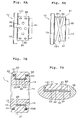
- Another example of the non-contact portion may be a plurality of recesses 35, such as depicted in Fig. 6A , which are formed dispersedly in the outer circumferential surface 31 of the resin liner 30.
- the planar shape of the recess 35 may be a circular or elliptic, for example. Without being limited to this, however, it is possible to adopt any shape. Further, the recess 35 described above may coexist with one of or both of grooves 32 and 33.
- grooves 34 shown in Fig. 6B as the non-contact portion, which extends in oblique directions in relation to the axial direction.
- two grooves 34 are formed symmetrically with respect to a plane P orthogonal to the axial direction of the inner ring 10.
- Each of the two grooves 34 is circumferential groove which is inclined from the axial direction and closed within the outer circumferential surface 11 of the inner ring 10.
- the grooves 34 may be spiral grooves reaching the both ends, in the axial direction, of the outer circumferential surface 11.
- the number of grooves 34 is not limited to two.
- the outer ring 20 shifts in the axial direction, the outer ring 20 or the washer 15 is pressed against the inner ring 10, and problems such as increase of the rotational torque are caused. Therefore, for preventing such kinds of problems, it is effective to form the grooves 34 symmetrically. Further, forming the non-contact portions symmetrically is effective not only in the case where the non-contact portions are grooves like grooves 34, but also, for example, in the case where the non-contact portions are the plurality of recesses 35 depicted in Fig. 6A .
- the resin liner 30 is formed on the outer circumferential surface 11 of the inner ring 10.
- the resin liner 30 according to the present invention may be formed on at least one of the outer circumferential surface 11 of the inner ring 10 and the inner circumferential surface 22 of the outer ring 20.
- the resin liner 30 may be formed on the inner circumferential surface 22 of the outer ring 20, and the non-contact portion, such as the groove 32 and the like, in which the resin liner 30 does not contact the outer circumferential surface 11 of the inner ring 10, may be formed in the resin liner 30 provided on the outer ring 20 side.
- a track roller bearing of working example 1 and a track roller bearing of working example 2 were obtained. Further, a track roller bearing having the same configuration as the track roller bearing depicted in Fig. 1 , except that the outer circumferential surface of the resin liner does not have non-contact portion, was made and used as comparative example 1.
- the endurance test is designed to continuously and reciprocatingly rotate the outer rings of track roller bearings T by interposing a track plate S between the track roller bearings T as depicted in Fig. 8 , and reciprocatingly moving the track plate S in the left-right directions in the Fig.8 while pressing the track roller bearings T against the track plate S with a load F in the radial direction.
- the endurance experiment was carried out by reciprocatingly rotating the outer rings 300,000 times while applying the radial load of 8.6 kN on the track roller bearings T, and it was investigated whether or not the outer rings slipped on the track plate S. The result is shown in the table 1.
- Working example 1 No slip occurred after 300,000 rotations
- Working example 2 No slip occurred after 300,000 rotations
- the outer rings slipped after 215,000 rotations.
- the outer rings did not slip even after 300,000 rotations and kept themselves in a rotatable state.
- the slips are prevented from occurring for a long period of time by forming the non-contact portions in the outer circumferential surface of the resin liner.
Landscapes
- Engineering & Computer Science (AREA)
- General Engineering & Computer Science (AREA)
- Mechanical Engineering (AREA)
- Sliding-Contact Bearings (AREA)
- Rolling Contact Bearings (AREA)
Abstract
Description
- The present invention relates to track roller bearings whose inner ring and outer ring are combined in a slidably rotatable manner via a resin liner and, in particular, to a track roller bearing suitable for use under high load condition.
- In an airplane wing, track roller bearings are applied to slats provided in a leading edge portion of the wing and to flaps provided in a trailing edge portion of the wing in such a way that the slats and flaps are extendable and retractable in the front-rear direction (see the
patent document 1 mentioned below) . Thispatent document 1 discloses a track roller bearing of such a configuration that the inner ring (inside ring) rotatably supports the outer ring (outside ring) while a self-lubricating resin liner is provided between the inner ring and the outer ring. In the track roller bearing described in thepatent document 1, the outer ring contacts the track and rotates to move the track roller bearing along the track. Therefore, the slat and flap are supported by the track roller bearing in a state that the slat and flap are capable of extending and retracting. Because the slat and flap are devices to increase or decrease the lift of the wing, the track roller bearing is subjected to a significantly high load. - Patent Document 1: Japanese Patent Application Laid-open No.
2009-137574 - In such a track roller bearing as disclosed in the
patent document 1, a sliding surface of the liner may be abraded away, and abrasion powder produced by the abrasion may adhere to the sliding surface. If the abrasion powder from the liner adheres to the sliding surface, the rotational torque for rotating the outer ring increases due to the increase of the outer diameter of the sliding surface resulting in a high rotational resistance of the outer ring. Once this problem happens, the outer ring can no longer rotate smoothly and the outer ring slips instead of rotating. In addition, slips may occur when the outer ring is pressed against the track under high load and is abraded away. Considering that a significantly high load is applied to the track roller bearing used in the aforementioned slat or flap, the problem mentioned above is likely to occur. However, it is necessary to prevent the slips from occurring for safety reasons. Therefore, more effective measures for slip prevention are being required. - The present invention is made in view of the above problem, and a primary object thereof is to provide a track roller bearing capable of maintaining its smooth rotation for a long period of time to thereby effectively reduce slips.
- A track roller bearing related to an aspect of the present invention includes:
- an inner ring;
- an outer ring which is concentric and rotatable relative to the inner ring;
- a resin liner formed on at least one of an outer circumferential surface of the inner ring and an inner circumferential surface of the outer ring; and
- an opposite surface which slides on a liner sliding surface of the resin liner,
- wherein a non-contact portion is formed in an area in which the resin liner is formed, the non-contact portion being a portion in which the liner sliding surface does not contact the opposite surface.
- In the track roller bearing of the present invention, when the inner ring and the outer ring rotate relative to each other, the liner sliding surface slides on the opposite surface. According to the present invention, by forming the non-contact portion in which the liner sliding surface does not contact the opposite surface,
within the area where the resin liner is formed, the resin liner has a smaller sliding area against the opposite surface on the other side than in the case of not forming the non-contact portion. On the other hand, any abrasion powder produced by abrading away the resin liner is brought into the non-contact portion to suppress the abrasion powder from adhering to the liner sliding surface. Therefore, an increase of the rotary torque for the track roller bearing is suppressed. Further, because there is an increase in the contact surface pressure of the resin liner, the friction coefficient of the resin liner decreases and the rotational resistance of the outer ring is reduced. From these factors, it is realizable for the outer ring to rotate smoothly for a long period. As a result, slips of the outer ring are reduced. - The non-contact portion of the present invention may be configured in any shape. The non-contact portion, for example, can be a groove extending in at least one of a circumferential direction of the liner sliding surface (a circumferential direction of the inner and outer rings), an axial direction of the liner sliding surface (an axial direction of the inner and outer rings), and an direction oblique to the axial direction. Further, the non-contact portion may be a plurality of recesses formed dispersedly. Further, the present invention includes such an aspect that a surface on which the resin liner is formed, is covered with the resin liner in the non-contact portion, the surface being the outer circumferential surface of the inner ring and/or the inner circumferential surface of the outer ring. Furthermore, the present invention also includes such an aspect that a surface on which the resin liner is formed, is not covered with the resin liner in the non-contact portion, the surface being the outer circumferential surface of the inner ring and/or the inner circumferential surface of the outer ring, and a surface which defines a bottom of the non-contact portion includes a plane in continuity with in interface between the resin liner and the surface on which the resin liner is formed, or a plane farther from the surface of the resin liner than the interface.
- Further, the present invention also includes such an aspect that the non-contact portion is provided symmetrically with respect to a plan orthogonal to an axial direction of the inner ring and the outer ring. According to the present invention, in some configurations of the non-contact portion, a component force acting on the outer ring in the axial direction may be brought about when the inner ring and the outer ring rotate relative to each other. For example, if the non-contact portion is a single groove extending in an oblique direction to intersect the axial direction, then such component force is brought about. However, if a plurality of grooves are formed symmetrically with respect to the plane orthogonal to the axial direction, then the component forces brought about in the axial direction cancel out. Hence, obstruction of the rotation of the track roller bearing due to deviation, in the axial direction, of the outer ring is suppressed.
- According to the present invention, it is possible to provide a track roller bearing which maintains its smooth rotation for a long period of time to thereby effectively reduce slips.
-
-
Fig. 1A is an overall vertical cross-sectional view of a track roller bearing related to an embodiment of the present invention; -
Fig. 1B is an enlarged cross-sectional view depicting a liner of the track roller bearing related to the embodiment of the present invention; -
Fig. 2 is an exploded perspective view of the track roller bearing; -
Figs. 3A and 3B depicts non-contact portions of the resin liner as grooves extending in a circumferential direction, whereinFig. 3A is a lateral view of an inner ring of the track roller bearing whileFig. 3B is a perspective view of the inner ring of the track roller bearing; -
Figs. 4A and 4B depicts non-contact portions of the resin liner as grooves extending in an axial direction, whereinFig. 4A is a lateral view of an inner ring of the track roller bearing whileFig. 4B is a perspective view of the inner ring of the track roller bearing; -
Figs. 5A, 5B and 5C are cross-sectional views depicting configurations of the depth of the grooves each of which is the non-contact portion (that is, views depicting cross-sectional shapes of the parts having the grooves); -
Figs. 6A and 6B are lateral views of inner rings, depicting non-contact portions related to other embodiments; -
Fig. 7A is an overall vertical cross-sectional view depicting a track roller bearing related to still another embodiment wherein the resin liner formed with the non-contact portions is provided on the outer ring side; -
Fig. 7B is an enlarged cross-sectional view depicting the resin liner of the track roller bearing related to the still other embodiment; and -
Fig. 8 is a schematic view of an endurance test carried out for working examples. - Referring to the accompanying drawings, explanations will be made below on embodiments in which the present invention is applied to a track roller bearing.
-
Fig. 1A is a vertical cross-sectional view of atrack roller bearing 1 related to one embodiment.Fig. 2 is an exploded perspective view of thetrack roller bearing 1. Thetrack roller bearing 1 includes a circularinner ring 10 and a circularouter ring 20 made of a metal such as stainless steel or the like. Theinner ring 10 and theouter ring 20 are assembled in such a manner as concentric and rotatable relative to each other. A fixed shaft, which is not depicted, is inserted through a throughhole 19 of theinner ring 10 and theinner ring 10 is fixed on the fixed shaft. That is, theinner ring 10 is on the fixed side while theouter ring 20 is used in such a state as assembled to be rotatable relative to theinner ring 10. Note that, in the following explanations, the axial direction refers to the axial directions of theinner ring 10 and theouter ring 20 while the circumferential direction refers to the circumferential directions of theinner ring 10 and theouter ring 20. - The
track roller bearing 1 according to the embodiment is mounted, for example, on a movable member which is supported to be movable in front-back direction, in a manner that the axial direction of thetrack roller bearing 1 is orthogonal to the movement in front or back direction of the movable member, and thetrack roller bearing 1 is used in a state that the outercircumferential surface 21 of theouter ring 20 is in contact with a track having a guide rail shape. In this state, theouter ring 20 of thetrack roller bearing 1 rotates to follow the movement of the movable member while being subjected to the load from the movable member. By this rotation, thetrack roller bearing 1 guides the movement of the movable member. Examples of the movable member can be the aforementioned slat or flap provided in an airplane wing. - On one end of the
inner ring 10 in the axial direction (left end of theinner ring 10 inFig. 1A ), aflange portion 13 is formed to project outwardly in a radial direction. Further, on the other end of theinner ring 10 in the axial direction (right end of theinner ring 10 inFig. 1A ), asmall diameter portion 14 is formed. Awasher 15 is fitted and fixed to thesmall diameter portion 14. Theouter ring 20 is rotatably fitted to an outercircumferential surface 11 of theinner ring 10 positioned between thewasher 15 and theflange portion 13 , with an interveningresin liner 30. Theresin liner 30 is formed on the outercircumferential surface 11 of theinner ring 10 and on aninner end face 131 of theflange portion 13. Further, theresin liner 30 is also formed on aninner end face 151 of thewasher 15. - On outer circumferential portions at the both ends of the
outer ring 20 in the axial direction,annular projections 23 are formed projecting outwardly in the axial direction. Theouter ring 20 is rotatably fitted on the outercircumferential surface 11 of theinner ring 10 via theresin liner 30. When theouter ring 20 rotates, an innercircumferential surface 22 of theouter ring 20 slides on an outercircumferential surface 31 of theresin liner 30. The inside of thetrack roller bearing 1, that is, the interspace defined between theinner ring 10 and theouter ring 20, is sealed up by a pair of seal rings 40 fitted in the both ends of theouter ring 20 in the axial direction. Oneseal ring 40 of the pair of seal rings 40 is fitted between theannular projection 23 of theouter ring 20 and theflange portion 13 of theinner ring 10 in an elastically deformed state, while theother seal ring 40 of the pair of seal rings 40 is fitted between theannular projection 23 of theouter ring 20 and thewasher 15 in a elastically deformed state. On the inner circumferential surfaces of theannular projections 23 of theouter ring 20,circumferential grooves 232 are formed to retain the seal rings 40 in a removable manner. - The
track roller bearing 1 configured as above is assembled according to such a procedure as to insert theinner ring 10 through a throughhole 29 of theouter ring 20 retaining the seal rings 40 in thecircumferential grooves 232, and then fit and fix thewasher 15 into thesmall diameter portion 14 of theinner ring 10. - The
resin liner 30 described above is formed by covering the outercircumferential surface 11 of theinner ring 10 with a self-lubricating resin containing polytetrafluoroethylene (PTFE) as a solid lubricant. Examples of the resin which can serve as the primary constituent of theresin liner 30 described above is acrylic resin, epoxy resin, polyether ether ketone (PEEK), or the like. However, the resin is not limited to these materials. It is desirable for theresin liner 30 to be as thick as about 0.2 to 0.3 mm. - The present invention is characterized by a non-contact portion formed on the outer circumferential surface 31 (liner sliding surface) of the
resin liner 30, the non-contact portion being a portion at which theresin liner 30 does not contact the inner circumferential surface 22 (opposite surface) of theouter ring 20. Specific examples of the non-contact portion can begrooves 32 extending in the circumferential direction as depicted inFigs. 3A and 3B orgrooves 33 extending in the axial direction as depicted inFigs. 4A and 4B . Note that, inFigs. 1A and 1B and inFig. 2 ,single groove 32 extending in the circumferential direction is formed in theresin liner 30. - Three
grooves 32 are depicted inFigs. 3A and 3B . One of the threegrooves 32 is formed at the central part of theresin liner 30 in the axial direction, and one of the two remaininggrooves 32 is formed at each end of theresin liner 30 in the axial direction. Thegrooves 32 formed at the both ends of theresin liner 30 in the axial direction are narrower than thegroove 32 formed at the central part of theresin liner 30 in the axial direction. Note that, although thenarrow groove 32 formed at the side of thesmall diameter portion 14 is depicted inFigs. 3A and 3B as a portion opened to the end face, this portion becomes a groove having walls on both sides in the axial direction when thewasher 15 is fitted into thesmall diameter portion 14. Therefore, this portion is referred to as thegroove 32. According to the present invention, the number ofgrooves 32 extending in the circumferential direction is not limited to one as exemplified above. If a plurality ofgrooves 32 are formed, then it is preferable to arrange thegrooves 32 at equal intervals in the axial direction for dispersing the load equally. The plurality ofgrooves 33 which are depicted inFigs 4A and 4B and which extend in the axial direction are formed at equal intervals in the circumferential direction. Thesegrooves 33 are opened to the end face on the side of thesmall diameter portion 14. If thegroove 33 is adopted, it is preferable to form at least two ofsuch grooves 33 and, from the point of view of dispersing the load equally, it is preferable to arrange thegrooves 33 at equal intervals in the circumferential direction. Further, thegrooves circumferential surface 31 of theresin liner 30. - It is possible to form the
grooves resin liner 30 by means of a cutting operation or the like after forming theresin liner 30 on the entire surface of the outercircumferential surface 11 of theinner ring 10. In such cases, depths of thegrooves resin liner 30, such that the outercircumferential surface 11 of theinner ring 10 is covered by theresin liner 30 even in the non-contact portion (seeFig. 5A ). Alternatively, theresin liner 30 may be entirely removed from a portion in which the groove is formed, such that the outercircumferential surface 11 of theinner ring 10 is not covered by theresin liner 30 in the non-contact portion. In the latter case, it may be possible to adopt two configurations described below. In one configuration, bottom surfaces of thegrooves resin liner 30 and the outer circumferential surface 11 (See,Fig. 5B ) . In the other configuration, depth of the grooves are set to be larger than the thickness of theresin layer 30 by cutting the surface of the outercircumferential surface 11, that is, in this configuration bottom surfaces of thegrooves circumferential surface 31 than the interface between theresin liner 30 and the outer circumferential surface 11 (seeFig. 5C ) . In other words, the distances between the bottom surfaces of thegrooves circumferential surface 31 are larger than the distance between thecircumferential surface 31 and the interface of theresin liner 30 and the outercircumferential surface 11. Considering that it is possible to appropriately select the depth of thegrooves grooves grooves track roller bearing 1. - The
track roller bearing 1 is mounted to the movable member supported to be movable to extend and retract as described previously in a manner that the axial direction of thetrack roller bearing 1 is orthogonal to the movement direction of the movable member. Thetrack roller bearing 1 is used in a state that the outercircumferential surface 21 of theouter ring 20 is in contact with the track having a guide rail shape. Theouter ring 20 of thetrack roller bearing 1 rotates to follow the extension or retraction movement of the movable member, thereby guiding the movement of the movable member. As theouter ring 20 rotates, the innercircumferential surface 22 of theouter ring 20 slides on the outercircumferential surface 31 of theresin liner 30. Thus, by virtue of the effect of the self-lubricatingresin liner 30, theouter ring 20 rotates smoothly. - In the
track roller bearing 1 mentioned above, the grooves 32 (33) are formed as the non-contact portions in the outercircumferential surface 31, that is the liner sliding surface, of theresin liner 30, the non-contact portions being portions in each of which the outercircumferential surface 31 of theresin liner 30 does not contact the innercircumferential surface 22 of theouter ring 20. By forming the non-contact portions in this manner, theresin liner 30 has a smaller sliding area against theouter ring 20 than in the case of not forming the non-contact portions. On the other hand, if the innercircumferential surface 22 of theouter ring 20 slides on the outercircumferential surface 31 of theresin liner 30, then the outercircumferential surface 31 of theresin liner 30 is abraded away to produce abrasion powder. The rotatingouter ring 20 brings the abrasion powder into the grooves 32 (33) to restrain the abrasion powder from adhering to the sliding surface of theouter ring 20 or theresin liner 30. Therefore, when thetrack roller bearing 1 is subject to the load, increase of a rotary torque needed to rotate theouter ring 20 is suppressed. Further, because there is an increase in the contact surface pressure of theresin liner 30, the friction coefficient decreases and the rotational resistance of theouter ring 20 is reduced. From these factors, it is possible for theouter ring 20 to rotate smoothly for a long period even being under high load. As a result, the occurrence of a problem like theouter ring 20 slipping instead of rotating is suppressed. - In the above embodiment, as representative examples of the non-contact portions of the present invention, the
grooves 32 extending in the circumferential direction and thegrooves 33 extending in the axial direction, both provided in the outercircumferential surface 31 of theresin liner 30, were explained. However, the non-contact portions of the present invention are not limited to these configurations. Another example of the non-contact portion may be a plurality ofrecesses 35, such as depicted inFig. 6A , which are formed dispersedly in the outercircumferential surface 31 of theresin liner 30. The planar shape of therecess 35 may be a circular or elliptic, for example. Without being limited to this, however, it is possible to adopt any shape. Further, therecess 35 described above may coexist with one of or both ofgrooves - Further, it is possible to adopt
grooves 34 shown inFig. 6B as the non-contact portion, which extends in oblique directions in relation to the axial direction. According to the embodiment depicted inFig. 6B , twogrooves 34 are formed symmetrically with respect to a plane P orthogonal to the axial direction of theinner ring 10. Each of the twogrooves 34 is circumferential groove which is inclined from the axial direction and closed within the outercircumferential surface 11 of theinner ring 10. However, thegrooves 34 may be spiral grooves reaching the both ends, in the axial direction, of the outercircumferential surface 11. Further, the number ofgrooves 34 is not limited to two. - The following is the reason for forming the
grooves 34 symmetrically with respect to the plane P orthogonal to the axial direction of theinner ring 10. That is, if only onegroove 34 extending in an oblique direction is provided, for example, then due to thissingle groove 34, a component force in the axial direction may be generated when theouter ring 20 rotates. If the component force is generated, then theouter ring 20 is pressed in the axial direction of theinner ring 10 or thewasher 15 as theouter ring 20 rotates. However, when twogrooves 34 are formed symmetrically, the component forces generated by the respective grooves cancel each other, and thus the action of the axial force on theouter ring 20 is suppressed. If theouter ring 20 shifts in the axial direction, theouter ring 20 or thewasher 15 is pressed against theinner ring 10, and problems such as increase of the rotational torque are caused. Therefore, for preventing such kinds of problems, it is effective to form thegrooves 34 symmetrically. Further, forming the non-contact portions symmetrically is effective not only in the case where the non-contact portions are grooves likegrooves 34, but also, for example, in the case where the non-contact portions are the plurality ofrecesses 35 depicted inFig. 6A . - Further, in all of the above embodiments, the
resin liner 30 is formed on the outercircumferential surface 11 of theinner ring 10. However, theresin liner 30 according to the present invention may be formed on at least one of the outercircumferential surface 11 of theinner ring 10 and the innercircumferential surface 22 of theouter ring 20. Hence, as depicted inFigs. 7A and 7B , theresin liner 30 may be formed on the innercircumferential surface 22 of theouter ring 20, and the non-contact portion, such as thegroove 32 and the like, in which theresin liner 30 does not contact the outercircumferential surface 11 of theinner ring 10, may be formed in theresin liner 30 provided on theouter ring 20 side. - Using each of the inner rings depicted in
Figs. 3A and 3B andFigs. 4A and 4B in the track roller bearing having the structure depicted inFig. 1 , a track roller bearing of working example 1 and a track roller bearing of working example 2 were obtained. Further, a track roller bearing having the same configuration as the track roller bearing depicted inFig. 1 , except that the outer circumferential surface of the resin liner does not have non-contact portion, was made and used as comparative example 1. For the track roller bearings of the working examples 1 and 2 and comparative example 1, an endurance test was carried out in which the outer ring was reciprocatingly rotated while a load in the radial direction of the outer ring was applied on the outer ring, and confirmation was made as to how many time can each of outer rings rotates before it slips. - The endurance test is designed to continuously and reciprocatingly rotate the outer rings of track roller bearings T by interposing a track plate S between the track roller bearings T as depicted in
Fig. 8 , and reciprocatingly moving the track plate S in the left-right directions in theFig.8 while pressing the track roller bearings T against the track plate S with a load F in the radial direction. The endurance experiment was carried out by reciprocatingly rotating the outer rings 300,000 times while applying the radial load of 8.6 kN on the track roller bearings T, and it was investigated whether or not the outer rings slipped on the track plate S. The result is shown in the table 1.<Table 1> Comparative example 1 Slip occurred after 215,000 rotations Working example 1 No slip occurred after 300,000 rotations Working example 2 No slip occurred after 300,000 rotations - According to the table 1, in the track roller bearings of the comparative example 1, the outer rings slipped after 215,000 rotations. In contrast, in the track roller bearings of the working examples 1 and 2 of the present invention, the outer rings did not slip even after 300,000 rotations and kept themselves in a rotatable state. Thus, it was verified that the slips are prevented from occurring for a long period of time by forming the non-contact portions in the outer circumferential surface of the resin liner.
- It is suitable to apply the track roller bearing according to the present invention to slats and/or flaps provided in an airplane wing.
-
- 1 track roller bearing, 10 inner ring, 11 outer circumferential surface of the inner ring, 20 outer ring, 22 inner circumferential surface of the outer ring (opposite surface), 30 resin liner, 31 outer circumferential surface of the resin liner (liner sliding surface), 32,33,34 groove (non-contact portion), 35 recess (non-contact portion), P plane orthogonal to the axial direction.
Claims (8)
- A track roller bearing characterized by comprising:an inner ring;an outer ring which is concentric and rotatable relative to the inner ring;a resin liner formed on at least one of an outer circumferential surface of the inner ring and an inner circumferential surface of the outer ring; andan opposite surface which slides on a liner sliding surface of the resin liner,wherein a non-contact portion is formed in an area in which the resin liner is formed, the non-contact portion being a portion in which the liner sliding surface does not contact the opposite surface.
- The track roller bearing according to claim 1, characterized in that the non-contact portion is a groove.
- The track roller bearing according to claim 1, characterized in that the non-contact portion is a plurality of recesses formed dispersedly.
- The track roller bearing according to any one of claims 1 to 3, characterized in that a surface on which the resin liner is formed, is covered with the resin liner in the non-contact portion, the surface being the outer circumferential surface of the inner ring and/or the inner circumferential surface of the outer ring.
- The track roller bearing according to any one of claims 1 to 3, characterized in that a surface on which the resin liner is formed, is not covered with the resin liner in the non-contact portion, the surface being the outer circumferential surface of the inner ring and/or the inner circumferential surface of the outer ring, and a surface which defines a bottom of the non-contact portion includes a plane in continuity with an interface between the resin liner and the surface on which the resin liner is formed, or a plane farther from the surface of the resin liner than the interface.
- The track roller bearing according to any one of claims 1 to 5, characterized in that the non-contact portion is provided symmetrically with respect to a plane orthogonal to an axial direction of the inner ring and the outer ring.
- The track roller bearing according to any one of claims 1 to 6, characterized in that the resin liner is formed on the outer circumferential surface of the inner ring and the opposite surface is defined on the inner circumferential surface of the outer ring.
- The track roller bearing according to any one of claims 1 to 6, characterized in that the resin liner is formed on the inner circumferential surface of the outer ring and the opposite surface is defined on the outer circumferential surface of the inner ring.
Applications Claiming Priority (1)
| Application Number | Priority Date | Filing Date | Title |
|---|---|---|---|
| JP2015071041A JP2016191410A (en) | 2015-03-31 | 2015-03-31 | Track roller bearing |
Publications (2)
| Publication Number | Publication Date |
|---|---|
| EP3076034A1 true EP3076034A1 (en) | 2016-10-05 |
| EP3076034B1 EP3076034B1 (en) | 2019-02-27 |
Family
ID=55640624
Family Applications (1)
| Application Number | Title | Priority Date | Filing Date |
|---|---|---|---|
| EP16162725.2A Active EP3076034B1 (en) | 2015-03-31 | 2016-03-30 | Track roller bearing |
Country Status (3)
| Country | Link |
|---|---|
| US (1) | US20160290400A1 (en) |
| EP (1) | EP3076034B1 (en) |
| JP (1) | JP2016191410A (en) |
Cited By (2)
| Publication number | Priority date | Publication date | Assignee | Title |
|---|---|---|---|---|
| CN114275145A (en) * | 2021-12-30 | 2022-04-05 | 湖北三江航天红阳机电有限公司 | A hot air flow blocking structure |
| US12031578B2 (en) | 2018-07-10 | 2024-07-09 | Hydromecanique Et Frottement | Hinged component, and mechanical system comprising such a component |
Families Citing this family (1)
| Publication number | Priority date | Publication date | Assignee | Title |
|---|---|---|---|---|
| US10443650B2 (en) | 2017-04-13 | 2019-10-15 | Roller Bearing Company Of America, Inc. | Two part seal assembly for a track roller bearing |
Citations (2)
| Publication number | Priority date | Publication date | Assignee | Title |
|---|---|---|---|---|
| JP2009137574A (en) | 2007-12-06 | 2009-06-25 | Roller Bearing Co Of America Inc | Drive system for lift assisting device and roller bearing used therein |
| EP2840272A2 (en) * | 2013-07-12 | 2015-02-25 | Roller Bearing Company of America, Inc. | Electrical conductor for bearing used on actuation system for aircraft lift assisting devices |
Family Cites Families (18)
| Publication number | Priority date | Publication date | Assignee | Title |
|---|---|---|---|---|
| US2675283A (en) * | 1949-11-19 | 1954-04-13 | John B Thomson | Bearing |
| US2815253A (en) * | 1954-01-15 | 1957-12-03 | Nylacore Corp | Bearing liner |
| US3575787A (en) * | 1969-01-13 | 1971-04-20 | Clevite Corp | Plastic bearing-bushing material |
| US3909087A (en) * | 1973-01-17 | 1975-09-30 | Garlock Inc | Composite bearings |
| US4717268A (en) * | 1981-04-20 | 1988-01-05 | Kamatics Corporation | Bearing construction |
| GB2097486B (en) * | 1981-04-20 | 1985-07-10 | Kamatics Corp | Bearings |
| US5137374A (en) * | 1981-04-20 | 1992-08-11 | Kamatics Corporation | Titanium bearing surface |
| US4428689A (en) * | 1981-04-21 | 1984-01-31 | Sargent Industries, Inc. | Bearing |
| US4685184A (en) * | 1984-09-21 | 1987-08-11 | Mcgill Manufacturing Company, Inc. | Self-lubricated track-roller bearing and method of constructing the same |
| US5219232A (en) * | 1991-11-27 | 1993-06-15 | Tiodize Company, Inc. | Floating bushing roller bearing |
| AT409409B (en) * | 1996-01-30 | 2002-08-26 | Glyco Metall Werke | SLIDING BEARING ELEMENT WITH LUBRICANTS |
| JP2002155945A (en) * | 2000-11-20 | 2002-05-31 | Daido Metal Co Ltd | Shaft bearing member |
| US6729763B2 (en) * | 2001-11-16 | 2004-05-04 | Kamatics Corporation | Hybrid bearing system |
| US20060083451A1 (en) * | 2003-01-08 | 2006-04-20 | Kimio Kawagoe | Sliding bearing |
| JP2008014454A (en) * | 2006-07-07 | 2008-01-24 | Daido Metal Co Ltd | Sliding bearing |
| US20140131512A1 (en) * | 2007-12-06 | 2014-05-15 | Roller Bearing Company Of America, Inc. | Seal and electrical conductor for lined track rollers used on actuation system for aircraft lift assisting devices |
| BRPI0924025B1 (en) * | 2008-12-05 | 2021-01-19 | Doosan Infracore Co., Ltd. | slide bearing and slide bearing assembly |
| JP2011033142A (en) * | 2009-08-03 | 2011-02-17 | Ntn Corp | Cam follower |
-
2015
- 2015-03-31 JP JP2015071041A patent/JP2016191410A/en active Pending
-
2016
- 2016-03-29 US US15/084,106 patent/US20160290400A1/en not_active Abandoned
- 2016-03-30 EP EP16162725.2A patent/EP3076034B1/en active Active
Patent Citations (2)
| Publication number | Priority date | Publication date | Assignee | Title |
|---|---|---|---|---|
| JP2009137574A (en) | 2007-12-06 | 2009-06-25 | Roller Bearing Co Of America Inc | Drive system for lift assisting device and roller bearing used therein |
| EP2840272A2 (en) * | 2013-07-12 | 2015-02-25 | Roller Bearing Company of America, Inc. | Electrical conductor for bearing used on actuation system for aircraft lift assisting devices |
Cited By (4)
| Publication number | Priority date | Publication date | Assignee | Title |
|---|---|---|---|---|
| US12031578B2 (en) | 2018-07-10 | 2024-07-09 | Hydromecanique Et Frottement | Hinged component, and mechanical system comprising such a component |
| US12203504B2 (en) | 2018-07-10 | 2025-01-21 | Hydromecanique Et Frottement | Hinged component and mechanical system comprising such a component |
| CN114275145A (en) * | 2021-12-30 | 2022-04-05 | 湖北三江航天红阳机电有限公司 | A hot air flow blocking structure |
| CN114275145B (en) * | 2021-12-30 | 2023-10-20 | 湖北三江航天红阳机电有限公司 | A hot air flow blocking structure |
Also Published As
| Publication number | Publication date |
|---|---|
| EP3076034B1 (en) | 2019-02-27 |
| JP2016191410A (en) | 2016-11-10 |
| US20160290400A1 (en) | 2016-10-06 |
Similar Documents
| Publication | Publication Date | Title |
|---|---|---|
| EP3076034B1 (en) | Track roller bearing | |
| EP3098486B1 (en) | Sealing ring | |
| KR20210121229A (en) | sliding parts | |
| EP2816262B1 (en) | Shaft-sealing device | |
| CN108368919B (en) | Flat type wave gear device | |
| US9726292B2 (en) | Seal rings | |
| KR20150035395A (en) | Rotative assembly, method for dismounting a sealing element and extraction tool for dismounting a sealing element | |
| US10189070B2 (en) | Roller for roll forming | |
| EP2653756B1 (en) | Seal ring | |
| EP3273116A1 (en) | Seal ring | |
| WO2015122099A1 (en) | Ball bearing with seal | |
| EP3385577A1 (en) | Shaft and seal structure | |
| EP3385579B1 (en) | Seal device | |
| KR101297542B1 (en) | Sealing Device | |
| EP3034899B1 (en) | Seal for self aligning roller bearing | |
| WO2020255591A1 (en) | Sealing device | |
| EP2832995A1 (en) | Swash plate | |
| DE102014209234A1 (en) | sealing arrangement | |
| CN115605694A (en) | Sealed structure | |
| EP3230629B1 (en) | Bearing isolator seal with tapered static shutoff o-ring interface | |
| EP4328460A1 (en) | Sliding component | |
| JP5598000B2 (en) | Seal ring | |
| KR20150139455A (en) | Composite annular seal assembly for bearings in aircraft | |
| WO2016091671A1 (en) | A roller bearing as well as a cage suitable for such a roller bearing | |
| JP5483230B2 (en) | Bone cutting instrument |
Legal Events
| Date | Code | Title | Description |
|---|---|---|---|
| PUAI | Public reference made under article 153(3) epc to a published international application that has entered the european phase |
Free format text: ORIGINAL CODE: 0009012 |
|
| AK | Designated contracting states |
Kind code of ref document: A1 Designated state(s): AL AT BE BG CH CY CZ DE DK EE ES FI FR GB GR HR HU IE IS IT LI LT LU LV MC MK MT NL NO PL PT RO RS SE SI SK SM TR |
|
| AX | Request for extension of the european patent |
Extension state: BA ME |
|
| STAA | Information on the status of an ep patent application or granted ep patent |
Free format text: STATUS: REQUEST FOR EXAMINATION WAS MADE |
|
| 17P | Request for examination filed |
Effective date: 20170403 |
|
| RBV | Designated contracting states (corrected) |
Designated state(s): AL AT BE BG CH CY CZ DE DK EE ES FI FR GB GR HR HU IE IS IT LI LT LU LV MC MK MT NL NO PL PT RO RS SE SI SK SM TR |
|
| RIC1 | Information provided on ipc code assigned before grant |
Ipc: F16C 13/00 20060101AFI20180202BHEP |
|
| STAA | Information on the status of an ep patent application or granted ep patent |
Free format text: STATUS: EXAMINATION IS IN PROGRESS |
|
| 17Q | First examination report despatched |
Effective date: 20180319 |
|
| GRAP | Despatch of communication of intention to grant a patent |
Free format text: ORIGINAL CODE: EPIDOSNIGR1 |
|
| STAA | Information on the status of an ep patent application or granted ep patent |
Free format text: STATUS: GRANT OF PATENT IS INTENDED |
|
| INTG | Intention to grant announced |
Effective date: 20181019 |
|
| GRAS | Grant fee paid |
Free format text: ORIGINAL CODE: EPIDOSNIGR3 |
|
| GRAA | (expected) grant |
Free format text: ORIGINAL CODE: 0009210 |
|
| STAA | Information on the status of an ep patent application or granted ep patent |
Free format text: STATUS: THE PATENT HAS BEEN GRANTED |
|
| AK | Designated contracting states |
Kind code of ref document: B1 Designated state(s): AL AT BE BG CH CY CZ DE DK EE ES FI FR GB GR HR HU IE IS IT LI LT LU LV MC MK MT NL NO PL PT RO RS SE SI SK SM TR |
|
| REG | Reference to a national code |
Ref country code: GB Ref legal event code: FG4D |
|
| REG | Reference to a national code |
Ref country code: CH Ref legal event code: EP |
|
| REG | Reference to a national code |
Ref country code: DE Ref legal event code: R096 Ref document number: 602016010226 Country of ref document: DE |
|
| REG | Reference to a national code |
Ref country code: AT Ref legal event code: REF Ref document number: 1101796 Country of ref document: AT Kind code of ref document: T Effective date: 20190315 |
|
| REG | Reference to a national code |
Ref country code: IE Ref legal event code: FG4D |
|
| REG | Reference to a national code |
Ref country code: NL Ref legal event code: MP Effective date: 20190227 |
|
| REG | Reference to a national code |
Ref country code: LT Ref legal event code: MG4D |
|
| PG25 | Lapsed in a contracting state [announced via postgrant information from national office to epo] |
Ref country code: PT Free format text: LAPSE BECAUSE OF FAILURE TO SUBMIT A TRANSLATION OF THE DESCRIPTION OR TO PAY THE FEE WITHIN THE PRESCRIBED TIME-LIMIT Effective date: 20190627 Ref country code: NL Free format text: LAPSE BECAUSE OF FAILURE TO SUBMIT A TRANSLATION OF THE DESCRIPTION OR TO PAY THE FEE WITHIN THE PRESCRIBED TIME-LIMIT Effective date: 20190227 Ref country code: FI Free format text: LAPSE BECAUSE OF FAILURE TO SUBMIT A TRANSLATION OF THE DESCRIPTION OR TO PAY THE FEE WITHIN THE PRESCRIBED TIME-LIMIT Effective date: 20190227 Ref country code: NO Free format text: LAPSE BECAUSE OF FAILURE TO SUBMIT A TRANSLATION OF THE DESCRIPTION OR TO PAY THE FEE WITHIN THE PRESCRIBED TIME-LIMIT Effective date: 20190527 Ref country code: LT Free format text: LAPSE BECAUSE OF FAILURE TO SUBMIT A TRANSLATION OF THE DESCRIPTION OR TO PAY THE FEE WITHIN THE PRESCRIBED TIME-LIMIT Effective date: 20190227 Ref country code: SE Free format text: LAPSE BECAUSE OF FAILURE TO SUBMIT A TRANSLATION OF THE DESCRIPTION OR TO PAY THE FEE WITHIN THE PRESCRIBED TIME-LIMIT Effective date: 20190227 |
|
| PG25 | Lapsed in a contracting state [announced via postgrant information from national office to epo] |
Ref country code: BG Free format text: LAPSE BECAUSE OF FAILURE TO SUBMIT A TRANSLATION OF THE DESCRIPTION OR TO PAY THE FEE WITHIN THE PRESCRIBED TIME-LIMIT Effective date: 20190527 Ref country code: HR Free format text: LAPSE BECAUSE OF FAILURE TO SUBMIT A TRANSLATION OF THE DESCRIPTION OR TO PAY THE FEE WITHIN THE PRESCRIBED TIME-LIMIT Effective date: 20190227 Ref country code: IS Free format text: LAPSE BECAUSE OF FAILURE TO SUBMIT A TRANSLATION OF THE DESCRIPTION OR TO PAY THE FEE WITHIN THE PRESCRIBED TIME-LIMIT Effective date: 20190627 Ref country code: GR Free format text: LAPSE BECAUSE OF FAILURE TO SUBMIT A TRANSLATION OF THE DESCRIPTION OR TO PAY THE FEE WITHIN THE PRESCRIBED TIME-LIMIT Effective date: 20190528 Ref country code: LV Free format text: LAPSE BECAUSE OF FAILURE TO SUBMIT A TRANSLATION OF THE DESCRIPTION OR TO PAY THE FEE WITHIN THE PRESCRIBED TIME-LIMIT Effective date: 20190227 Ref country code: RS Free format text: LAPSE BECAUSE OF FAILURE TO SUBMIT A TRANSLATION OF THE DESCRIPTION OR TO PAY THE FEE WITHIN THE PRESCRIBED TIME-LIMIT Effective date: 20190227 |
|
| REG | Reference to a national code |
Ref country code: AT Ref legal event code: MK05 Ref document number: 1101796 Country of ref document: AT Kind code of ref document: T Effective date: 20190227 |
|
| PG25 | Lapsed in a contracting state [announced via postgrant information from national office to epo] |
Ref country code: CZ Free format text: LAPSE BECAUSE OF FAILURE TO SUBMIT A TRANSLATION OF THE DESCRIPTION OR TO PAY THE FEE WITHIN THE PRESCRIBED TIME-LIMIT Effective date: 20190227 Ref country code: RO Free format text: LAPSE BECAUSE OF FAILURE TO SUBMIT A TRANSLATION OF THE DESCRIPTION OR TO PAY THE FEE WITHIN THE PRESCRIBED TIME-LIMIT Effective date: 20190227 Ref country code: IT Free format text: LAPSE BECAUSE OF FAILURE TO SUBMIT A TRANSLATION OF THE DESCRIPTION OR TO PAY THE FEE WITHIN THE PRESCRIBED TIME-LIMIT Effective date: 20190227 Ref country code: SK Free format text: LAPSE BECAUSE OF FAILURE TO SUBMIT A TRANSLATION OF THE DESCRIPTION OR TO PAY THE FEE WITHIN THE PRESCRIBED TIME-LIMIT Effective date: 20190227 Ref country code: ES Free format text: LAPSE BECAUSE OF FAILURE TO SUBMIT A TRANSLATION OF THE DESCRIPTION OR TO PAY THE FEE WITHIN THE PRESCRIBED TIME-LIMIT Effective date: 20190227 Ref country code: DK Free format text: LAPSE BECAUSE OF FAILURE TO SUBMIT A TRANSLATION OF THE DESCRIPTION OR TO PAY THE FEE WITHIN THE PRESCRIBED TIME-LIMIT Effective date: 20190227 Ref country code: EE Free format text: LAPSE BECAUSE OF FAILURE TO SUBMIT A TRANSLATION OF THE DESCRIPTION OR TO PAY THE FEE WITHIN THE PRESCRIBED TIME-LIMIT Effective date: 20190227 Ref country code: AL Free format text: LAPSE BECAUSE OF FAILURE TO SUBMIT A TRANSLATION OF THE DESCRIPTION OR TO PAY THE FEE WITHIN THE PRESCRIBED TIME-LIMIT Effective date: 20190227 |
|
| REG | Reference to a national code |
Ref country code: CH Ref legal event code: PL |
|
| REG | Reference to a national code |
Ref country code: DE Ref legal event code: R097 Ref document number: 602016010226 Country of ref document: DE |
|
| PG25 | Lapsed in a contracting state [announced via postgrant information from national office to epo] |
Ref country code: LU Free format text: LAPSE BECAUSE OF NON-PAYMENT OF DUE FEES Effective date: 20190330 Ref country code: PL Free format text: LAPSE BECAUSE OF FAILURE TO SUBMIT A TRANSLATION OF THE DESCRIPTION OR TO PAY THE FEE WITHIN THE PRESCRIBED TIME-LIMIT Effective date: 20190227 Ref country code: SM Free format text: LAPSE BECAUSE OF FAILURE TO SUBMIT A TRANSLATION OF THE DESCRIPTION OR TO PAY THE FEE WITHIN THE PRESCRIBED TIME-LIMIT Effective date: 20190227 |
|
| REG | Reference to a national code |
Ref country code: BE Ref legal event code: MM Effective date: 20190331 |
|
| PG25 | Lapsed in a contracting state [announced via postgrant information from national office to epo] |
Ref country code: MC Free format text: LAPSE BECAUSE OF FAILURE TO SUBMIT A TRANSLATION OF THE DESCRIPTION OR TO PAY THE FEE WITHIN THE PRESCRIBED TIME-LIMIT Effective date: 20190227 Ref country code: AT Free format text: LAPSE BECAUSE OF FAILURE TO SUBMIT A TRANSLATION OF THE DESCRIPTION OR TO PAY THE FEE WITHIN THE PRESCRIBED TIME-LIMIT Effective date: 20190227 |
|
| PLBE | No opposition filed within time limit |
Free format text: ORIGINAL CODE: 0009261 |
|
| STAA | Information on the status of an ep patent application or granted ep patent |
Free format text: STATUS: NO OPPOSITION FILED WITHIN TIME LIMIT |
|
| PG25 | Lapsed in a contracting state [announced via postgrant information from national office to epo] |
Ref country code: CH Free format text: LAPSE BECAUSE OF NON-PAYMENT OF DUE FEES Effective date: 20190331 Ref country code: LI Free format text: LAPSE BECAUSE OF NON-PAYMENT OF DUE FEES Effective date: 20190331 Ref country code: IE Free format text: LAPSE BECAUSE OF NON-PAYMENT OF DUE FEES Effective date: 20190330 |
|
| 26N | No opposition filed |
Effective date: 20191128 |
|
| PG25 | Lapsed in a contracting state [announced via postgrant information from national office to epo] |
Ref country code: BE Free format text: LAPSE BECAUSE OF NON-PAYMENT OF DUE FEES Effective date: 20190331 Ref country code: SI Free format text: LAPSE BECAUSE OF FAILURE TO SUBMIT A TRANSLATION OF THE DESCRIPTION OR TO PAY THE FEE WITHIN THE PRESCRIBED TIME-LIMIT Effective date: 20190227 |
|
| PG25 | Lapsed in a contracting state [announced via postgrant information from national office to epo] |
Ref country code: TR Free format text: LAPSE BECAUSE OF FAILURE TO SUBMIT A TRANSLATION OF THE DESCRIPTION OR TO PAY THE FEE WITHIN THE PRESCRIBED TIME-LIMIT Effective date: 20190227 |
|
| PG25 | Lapsed in a contracting state [announced via postgrant information from national office to epo] |
Ref country code: MT Free format text: LAPSE BECAUSE OF NON-PAYMENT OF DUE FEES Effective date: 20190330 |
|
| GBPC | Gb: european patent ceased through non-payment of renewal fee |
Effective date: 20200330 |
|
| PG25 | Lapsed in a contracting state [announced via postgrant information from national office to epo] |
Ref country code: GB Free format text: LAPSE BECAUSE OF NON-PAYMENT OF DUE FEES Effective date: 20200330 |
|
| PG25 | Lapsed in a contracting state [announced via postgrant information from national office to epo] |
Ref country code: CY Free format text: LAPSE BECAUSE OF FAILURE TO SUBMIT A TRANSLATION OF THE DESCRIPTION OR TO PAY THE FEE WITHIN THE PRESCRIBED TIME-LIMIT Effective date: 20190227 |
|
| PG25 | Lapsed in a contracting state [announced via postgrant information from national office to epo] |
Ref country code: HU Free format text: LAPSE BECAUSE OF FAILURE TO SUBMIT A TRANSLATION OF THE DESCRIPTION OR TO PAY THE FEE WITHIN THE PRESCRIBED TIME-LIMIT; INVALID AB INITIO Effective date: 20160330 |
|
| PG25 | Lapsed in a contracting state [announced via postgrant information from national office to epo] |
Ref country code: MK Free format text: LAPSE BECAUSE OF FAILURE TO SUBMIT A TRANSLATION OF THE DESCRIPTION OR TO PAY THE FEE WITHIN THE PRESCRIBED TIME-LIMIT Effective date: 20190227 |
|
| REG | Reference to a national code |
Ref country code: DE Ref legal event code: R082 Ref document number: 602016010226 Country of ref document: DE Representative=s name: DENNEMEYER & ASSOCIATES S.A., DE Ref country code: DE Ref legal event code: R081 Ref document number: 602016010226 Country of ref document: DE Owner name: MINEBEA MITSUMI INC., JP Free format text: FORMER OWNER: MINEBEA CO., LTD., KITASAKU-GUN, NAGANO, JP Ref country code: DE Ref legal event code: R082 Ref document number: 602016010226 Country of ref document: DE Representative=s name: DENNEMEYER & ASSOCIATES RECHTSANWALTSGESELLSCH, DE |
|
| P01 | Opt-out of the competence of the unified patent court (upc) registered |
Free format text: CASE NUMBER: APP_10391/2025 Effective date: 20250303 |
|
| PGFP | Annual fee paid to national office [announced via postgrant information from national office to epo] |
Ref country code: FR Payment date: 20250325 Year of fee payment: 10 |
|
| REG | Reference to a national code |
Ref country code: DE Ref legal event code: R082 Ref document number: 602016010226 Country of ref document: DE Representative=s name: DENNEMEYER & ASSOCIATES RECHTSANWALTSGESELLSCH, DE |
|
| PGFP | Annual fee paid to national office [announced via postgrant information from national office to epo] |
Ref country code: DE Payment date: 20260319 Year of fee payment: 11 |