EP3076028A1 - Hydraulic valve device with multiple working sections - Google Patents
Hydraulic valve device with multiple working sections Download PDFInfo
- Publication number
- EP3076028A1 EP3076028A1 EP16163600.6A EP16163600A EP3076028A1 EP 3076028 A1 EP3076028 A1 EP 3076028A1 EP 16163600 A EP16163600 A EP 16163600A EP 3076028 A1 EP3076028 A1 EP 3076028A1
- Authority
- EP
- European Patent Office
- Prior art keywords
- elements
- channels
- separated
- circuits
- lines
- Prior art date
- Legal status (The legal status is an assumption and is not a legal conclusion. Google has not performed a legal analysis and makes no representation as to the accuracy of the status listed.)
- Granted
Links
Images



Classifications
-
- F—MECHANICAL ENGINEERING; LIGHTING; HEATING; WEAPONS; BLASTING
- F15—FLUID-PRESSURE ACTUATORS; HYDRAULICS OR PNEUMATICS IN GENERAL
- F15B—SYSTEMS ACTING BY MEANS OF FLUIDS IN GENERAL; FLUID-PRESSURE ACTUATORS, e.g. SERVOMOTORS; DETAILS OF FLUID-PRESSURE SYSTEMS, NOT OTHERWISE PROVIDED FOR
- F15B11/00—Servomotor systems without provision for follow-up action; Circuits therefor
- F15B11/16—Servomotor systems without provision for follow-up action; Circuits therefor with two or more servomotors
- F15B11/17—Servomotor systems without provision for follow-up action; Circuits therefor with two or more servomotors using two or more pumps
-
- E—FIXED CONSTRUCTIONS
- E02—HYDRAULIC ENGINEERING; FOUNDATIONS; SOIL SHIFTING
- E02F—DREDGING; SOIL-SHIFTING
- E02F9/00—Component parts of dredgers or soil-shifting machines, not restricted to one of the kinds covered by groups E02F3/00 - E02F7/00
- E02F9/20—Drives; Control devices
- E02F9/22—Hydraulic or pneumatic drives
- E02F9/2278—Hydraulic circuits
- E02F9/2282—Systems using center bypass type changeover valves
-
- E—FIXED CONSTRUCTIONS
- E02—HYDRAULIC ENGINEERING; FOUNDATIONS; SOIL SHIFTING
- E02F—DREDGING; SOIL-SHIFTING
- E02F9/00—Component parts of dredgers or soil-shifting machines, not restricted to one of the kinds covered by groups E02F3/00 - E02F7/00
- E02F9/20—Drives; Control devices
- E02F9/22—Hydraulic or pneumatic drives
- E02F9/2278—Hydraulic circuits
- E02F9/2292—Systems with two or more pumps
-
- E—FIXED CONSTRUCTIONS
- E02—HYDRAULIC ENGINEERING; FOUNDATIONS; SOIL SHIFTING
- E02F—DREDGING; SOIL-SHIFTING
- E02F9/00—Component parts of dredgers or soil-shifting machines, not restricted to one of the kinds covered by groups E02F3/00 - E02F7/00
- E02F9/20—Drives; Control devices
- E02F9/22—Hydraulic or pneumatic drives
- E02F9/2278—Hydraulic circuits
- E02F9/2296—Systems with a variable displacement pump
-
- F—MECHANICAL ENGINEERING; LIGHTING; HEATING; WEAPONS; BLASTING
- F15—FLUID-PRESSURE ACTUATORS; HYDRAULICS OR PNEUMATICS IN GENERAL
- F15B—SYSTEMS ACTING BY MEANS OF FLUIDS IN GENERAL; FLUID-PRESSURE ACTUATORS, e.g. SERVOMOTORS; DETAILS OF FLUID-PRESSURE SYSTEMS, NOT OTHERWISE PROVIDED FOR
- F15B2211/00—Circuits for servomotor systems
- F15B2211/20—Fluid pressure source, e.g. accumulator or variable axial piston pump
- F15B2211/205—Systems with pumps
- F15B2211/2053—Type of pump
- F15B2211/20546—Type of pump variable capacity
-
- F—MECHANICAL ENGINEERING; LIGHTING; HEATING; WEAPONS; BLASTING
- F15—FLUID-PRESSURE ACTUATORS; HYDRAULICS OR PNEUMATICS IN GENERAL
- F15B—SYSTEMS ACTING BY MEANS OF FLUIDS IN GENERAL; FLUID-PRESSURE ACTUATORS, e.g. SERVOMOTORS; DETAILS OF FLUID-PRESSURE SYSTEMS, NOT OTHERWISE PROVIDED FOR
- F15B2211/00—Circuits for servomotor systems
- F15B2211/20—Fluid pressure source, e.g. accumulator or variable axial piston pump
- F15B2211/205—Systems with pumps
- F15B2211/20576—Systems with pumps with multiple pumps
-
- F—MECHANICAL ENGINEERING; LIGHTING; HEATING; WEAPONS; BLASTING
- F15—FLUID-PRESSURE ACTUATORS; HYDRAULICS OR PNEUMATICS IN GENERAL
- F15B—SYSTEMS ACTING BY MEANS OF FLUIDS IN GENERAL; FLUID-PRESSURE ACTUATORS, e.g. SERVOMOTORS; DETAILS OF FLUID-PRESSURE SYSTEMS, NOT OTHERWISE PROVIDED FOR
- F15B2211/00—Circuits for servomotor systems
- F15B2211/30—Directional control
- F15B2211/305—Directional control characterised by the type of valves
- F15B2211/3056—Assemblies of multiple valves
- F15B2211/3059—Assemblies of multiple valves having multiple valves for multiple output members
- F15B2211/30595—Assemblies of multiple valves having multiple valves for multiple output members with additional valves between the groups of valves for multiple output members
-
- F—MECHANICAL ENGINEERING; LIGHTING; HEATING; WEAPONS; BLASTING
- F15—FLUID-PRESSURE ACTUATORS; HYDRAULICS OR PNEUMATICS IN GENERAL
- F15B—SYSTEMS ACTING BY MEANS OF FLUIDS IN GENERAL; FLUID-PRESSURE ACTUATORS, e.g. SERVOMOTORS; DETAILS OF FLUID-PRESSURE SYSTEMS, NOT OTHERWISE PROVIDED FOR
- F15B2211/00—Circuits for servomotor systems
- F15B2211/70—Output members, e.g. hydraulic motors or cylinders or control therefor
- F15B2211/71—Multiple output members, e.g. multiple hydraulic motors or cylinders
- F15B2211/7142—Multiple output members, e.g. multiple hydraulic motors or cylinders the output members being arranged in multiple groups
Definitions
- the present invention relates to the field of hydraulic valve devices, in particular LS flow-sharing with multiple working sections, for controlling two LS pumps. It is noted that the protection extends to all hydraulic distributors having the claimed valve device.
- the flow delivered by the pump in LS flow-sharing systems is divided among the various utilities in proportion to the requirement of the single spool so as to maintain the combined motion.
- the load-sensing flow-sharing distributors take the pressure after the spool and, once the LS signal is initiated, they send it to a delivery compensator which before the spool forces a delivery pressure equal to the LS pressure plus a fixed stand-by. This causes a fixed pressure stage through the dispensing recesses of the spool and thereby a fixed flow rate, irrespective of the LS pressure but only as a function of the passage area opened by the dispensing recesses of the spool.
- the distributor is provided with a system adapted to send the highest pressure among those actuated to the delivery compensator.
- a set of local compensators is provided, one for each element.
- FIG. 5 An example of the system described above is shown in figure 5 .
- the basic system described above has some limits which are found in the control of a machine tool.
- the main compensator in the case of constant or variable but non-LS displacement pumps, is inserted at the inlet of the distributor: in this way, the latter only sends the flow rate that generates the pressure stage forced by the compensator itself to the utility, while it laminates the excess flow rate directly to the bleed; in this case, therefore, all the flow rate sent by the pump is delivered at the pressure of the LS pressure (plus any stand-by), also that exceeding the demand, which is then laminated directly to the bleed by the compensator itself.
- the dissipation of energy due to the unused flow rate due to the working pressure is clear.
- the LS pump only sends the required flow rate undoubtedly allows an energy saving. If, however, multiple elements are simultaneously actuated, the pump certainly sends all the total flow rate required, which would be all increased to the pressure induced by the higher load, i.e. also the flow delivered to the utilities which would require lower pressures for operating, and the excess pressure would be dissipated by the local compensators of the elements with a lower load. It is clear that the difference between the total flow rate sent to the elements less than that sent to the utilities at a higher pressure multiplied by the difference in pressure between the utility with higher load and the other loads is all a dissipation of energy.
- Another advantage of a system having two LS pumps is in the shifting by means of tracks.
- An object of the present invention is to provide a load-sensing and flow-sharing (i.e. antisaturation) device, a valve device with multiple working sections and with dual pump operation logic, as part of a simple, rational and cost-effective solution.
- Another object of the present invention is to provide a load-sensing and flow-sharing device capable of improving the limits described above.
- the invention involves switching from one to two LS pumps, both actuated by a single endothermic motor while keeping the already known electronic management. Wherein each pump only delivers part of the valve elements.
- the LS flow-sharing directional valve although physically still a single unit, actually divides the elements and the corresponding utilities into two separate groups as if they were two separate LS circuits. This subdivision is obtained by means of an intermediate summation element having a spool 4 configured to define three positions.
- an embodiment of the present invention provides a solution which allows separating/combining two groups of utilities and the relative LS pumps according to the working conditions.
- said intermediate summation element electrically controlled by a CPU based on a series of inputs received by sensors placed on the machine and/or the distributor, it keeps the following separated, or keeps them combined, according to some operating logics described hereinafter,
- the circuit can be set to the most convenient configuration, both from the energy and from the functional point of view.
- each of the load-sensing channels provides a connection to respective so-called bleed channels (connection with bleed valves).
- valve device with dual-pump operation object of the present invention which is characterized by the claims below.
- a limitation of using a single LS pump is that if two utilities are actuated at different pressures, the entire flow rate delivered (sum of the flow rates required by the single spools) is delivered at the pressure of the utility with the highest pressure plus the stand-by value, i.e. also at the flow rate that actuates the utility at a lower pressure.
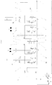
- the circuit shown in figure 1 describes the object of the invention. Overall, the circuit consists of two independent circuits separated by an intermediate summation element.
- the intermediate element 3 comprises a number of components, connected to one another through conduits, pathways and connections, capable of connecting or separating the two groups of elements (E1, E2) (E3, E4) with the relative side 1, 2 and delivering apparatus PA, PB.
- the intermediate summation element 3 is controlled by an electric or electro-hydraulic control in order to modify the LS circuit according to the working conditions of the machine tool, the latter comprising the hydraulic distributor operating according to the circuit diagram of the subject system 9.
- E1 and E2 are arranged between the inlet side 2 and the summation element 3, while elements E3 and E4 are arranged between the inlet side 1 and the summation element 3; such elements are then connected, through utilities A1, B1, A2, B2 ..., to the various utilities to be controlled.
- the two elements at the sides of the summation element 3 in the specific example E2 and E3 will be taken as reference as those that need to be connected to, and thus deliver, the hydraulic motors in turn actuating the tracks to move the machine tool.
- the valve circuit indicated with reference numeral 9 and describing the operation of a hydraulic distributor, comprises:
- the summation/separation element 3 is arranged between elements E1, E2, and E3, E4.
- the flow rate delivered by the PB pump feeds, through the high-pressure line P1, the inlet side 1, then elements E3 and E4 up to the summation element 3.
- the LS signal coming from elements E3 and E4 reaches the PB pump through the LS2 connection.
- the flow rate delivered by the PB pump feeds, through P2, the inlet side 2, then elements E1 and E2 up to the summation element 3.
- the LS signal coming from elements E1 and E2 reaches the PA pump through the LS1 connection.
- the summation/separation element 3 comprises at least one spool 4 whose movement, due to a proportional electro-hydraulic version controlled by a CPU based on the inputs from the various sensors already mentioned above, allows opening/closing connections between elements E1 and E2 and elements E3 and E4.
- spool 4 has three positions and connecting channels; controlled by a proportional electro-hydraulic version, allows connecting or separating channels P1 and P2, channels ST1 and ST2 and signals LS1 and LS2 to/from each other.
- the spool itself connects LS1 to its own bleed channel b1 and LS2 to its own bleed channel b2 separate from each other.
- LS1 and LS2 are both connected to only one of the 2 bleeds while the other is isolated; in this way, the energy dissipation is conveniently reduced due to the cancellation of the flow rate bled from the relative isolated valve.
- the circuit thus formed due to the presence of spool 4 of the summation element 3, fits itself to work according to a logic dictated by the working conditions of one and/or both circuits, by the loads required and by the pressures in the circuits.
- the two circuits with the relative pumps PA and PB must be combined in a single distributor, obtaining the complete union of the circuit, i.e. of the pump deliveries, of the connection channels between travels ST1 and ST2 and of the LS signals.
- the feeding rate of the third utility actuated would be subtracted only to one of the two elements E2, E3, causing an undesired steering of the excavator. Therefore, the summation element (3) must be placed in the second position II in Fig. 3 .
- the process can move on to a second level, as described hereinafter.
- the combination of the two groups has advantages when only one of the two groups is in saturation while the other requires little flow rate to its own pump, so as to exploit the capacity of the pump with low flow rate demand for feeding the group in saturation.
- the group in saturation has a pressure lower than that with a low flow rate (or not actuated). In this situation, only deliveries P1 and P2 of the pumps should be connected, but the load-sensing signals LS1 and LS2 should not. Due to natural lamination, this causes the flow rate passage from the high pressure group towards that in saturation and at a low pressure. However, without connecting the load-sensing signals LS1 and LS2, the pressure of the group in saturation keeps its low pressure, thus without the risk of switching to torque limitation and unnecessarily increasing the dissipated energy.
- the summation element (3) must proportionally move towards the third position in Fig. 1 , corresponding to the section in Fig. 4 .
- the proportionality of the control of spool 4 allows laminating, through the recesses of spool 4, the correct flow rate required by the group in saturation to come out of the saturation itself.
- the summation element 3 connects the two groups, as shown in the second position II. In other words, channels P1, P2 are connected, as are those of signals LS1, LS2. In doing so, the missing flow rate is provided to the group in saturation.
- the downside is that the pressure of the flow rate required by the other group is unnecessarily increased, although it has been defined as being little.
- circuit example in figure 1 and the relative positions of spool 4 indicated in Figures 2 , 3 , 4 are exemplary and non-limiting. That is to say, they may be exchanged without affecting the indicated operation logic and the control will take action to position the spool in the proper configuration.
- a hydraulic directional load-sensing flow-sharing system (9) is claimed, of the type comprising two independent circuits at the sides of an intermediate summation element (3).
- the intermediate summation element 3 comprises a spool 4 having at least three positions/configurations I, II, III of which:
- the proportional passage between the three positions is carried out through an electric/electro-hydraulic proportional control managed by a CPU as a function of inputs detected on the machine and/or on the distributor by means of suitable sensors, as described in the document.
- System 9 described is a valve body consisting of multiple sections, each serving multiple utilities and is also known by the term hydraulic distributor.
- the summation element 3 comprises a number of components, connected to one another through conduits, pathways and connections, capable of connecting or separating the two groups of elements with the relative side and LS pump.
- the valve circuit describing a hydraulic distributor comprises:
- the summation element 3 is arranged between elements E1, E2, and E3, E4.
- the summation element 3 comprises at least one spool 4 having three positions with connecting channels; it is further controlled by a proportional electro-hydraulic version which allows connecting or separating channels P1 and P2, channels ST1 and ST2 and signals LS1 and LS2 to/from each other.
- the spool itself connects LS1 to its own bleed valve b1 and LS2 to its own bleed valve b2, separate from each other.
- LS1 and LS2 are both connected to only one of the 2 bleeds while the other is isolated; in this way, the energy dissipation is conveniently reduced due to the cancellation of the flow rate bled from the relative isolated bleed valve.
- a further case is that in which the flow rate required by each of the two single groups is close to or higher than the value which causes the saturation of the pump.
- the combination would not create advantages of speed, since the two pumps are already almost to the maximum, on the contrary there would be the drawback of bringing both flow rates to the higher pressure, with the risk of triggering the torque limiter and consequently reducing the machine speed rather than increasing it. Therefore, spool 4 of the summation element 3 is kept in position I.
Landscapes
- Engineering & Computer Science (AREA)
- Physics & Mathematics (AREA)
- Fluid Mechanics (AREA)
- Mechanical Engineering (AREA)
- General Engineering & Computer Science (AREA)
- Fluid-Pressure Circuits (AREA)
Abstract
Description
- The present invention relates to the field of hydraulic valve devices, in particular LS flow-sharing with multiple working sections, for controlling two LS pumps. It is noted that the protection extends to all hydraulic distributors having the claimed valve device.
- Load-sensing flow-sharing directional valves with multiple sections are now part of the prior art. The same Applicant already has patents thereof (
US7182097 orEP1628018 ) and this prior art is the basis of the following innovation. However, even if it is prior art, the features of such LS flow-sharing directional valves combined with LS pumps in LS systems are summarized and the detailed operation thereof is disclosed inUS7182097 andEP1628018 . - It is known that the introduction of LS systems allows diversifying the flow rates to the single utilities, making such flow rates independent of loads and independent of the flows rates and pressures of the other utilities.
- Moreover, in the case of multiple actuations causing the pump saturation (when the flow required is greater than the maximum delivered by the pump), the flow delivered by the pump in LS flow-sharing systems is divided among the various utilities in proportion to the requirement of the single spool so as to maintain the combined motion.
- To this end, the load-sensing flow-sharing distributors take the pressure after the spool and, once the LS signal is initiated, they send it to a delivery compensator which before the spool forces a delivery pressure equal to the LS pressure plus a fixed stand-by. This causes a fixed pressure stage through the dispensing recesses of the spool and thereby a fixed flow rate, irrespective of the LS pressure but only as a function of the passage area opened by the dispensing recesses of the spool.
- In the case of concurrent actuation of multiple utilities, the distributor is provided with a system adapted to send the highest pressure among those actuated to the delivery compensator. To keep the load-sensing feature also in utilities with a lower pressure, a set of local compensators is provided, one for each element.
- The use of LS systems with LS variable displacement pumps allows considerable energy saving since the pump only delivers the required flow rate, i.e. that which generates the fixed stand-by set by the pump itself, unlike other systems in which the pump delivers all the flow rate and that exceeding the requirement is delivered directly to the bleed, with a clear energy dissipation.
- An example of the system described above is shown in
figure 5 . - The basic system described above has some limits which are found in the control of a machine tool.
- The main compensator, in the case of constant or variable but non-LS displacement pumps, is inserted at the inlet of the distributor: in this way, the latter only sends the flow rate that generates the pressure stage forced by the compensator itself to the utility, while it laminates the excess flow rate directly to the bleed; in this case, therefore, all the flow rate sent by the pump is delivered at the pressure of the LS pressure (plus any stand-by), also that exceeding the demand, which is then laminated directly to the bleed by the compensator itself. The dissipation of energy due to the unused flow rate due to the working pressure is clear.
- Significant energy saving occurs when the compensator is positioned on a variable displacement LS pump; in this case, this only sends the required flow rate, i.e. the one that generates the pressure stage forced by the compensator itself, and consequently there is no excess flow rate, with a clear energy saving.
- The fact that the LS pump only sends the required flow rate undoubtedly allows an energy saving. If, however, multiple elements are simultaneously actuated, the pump certainly sends all the total flow rate required, which would be all increased to the pressure induced by the higher load, i.e. also the flow delivered to the utilities which would require lower pressures for operating, and the excess pressure would be dissipated by the local compensators of the elements with a lower load. It is clear that the difference between the total flow rate sent to the elements less than that sent to the utilities at a higher pressure multiplied by the difference in pressure between the utility with higher load and the other loads is all a dissipation of energy.
- For constructional reasons, it is not feasible to connect to each utility to its own pump.
- However, it is possible to switch to hydraulic circuits delivered by at least two load-sensing, LS, pumps, each of which delivering two separate groups of utilities according to a logic dictated by the machine itself.
- An example of what has just been said is described in patent document
US5211014 . - The advantage of this solution is that, by operating two utilities on different groups, each flow rate will be subject to the load pressure of its own utility (also that with a lower load), with consequent energy saving.
- Another advantage of a system having two LS pumps is in the shifting by means of tracks.
- Let's take the case of single pump and straight traslation: the two tracks divide the flow rate delivered (moreover, it is common that the set of the two tracks requires the maximum flow rate than can be delivered by the pump). If one wanted to slightly steer in speed, the flow rate of one of the two tracks should be slightly decreased, with the result that the pressure of a track would tend to rise while the other to decrease. Therefore, in the case of single pump, the entire flow rate would be at the pressure dictated by the greater load: the torque limiter would be triggered and the machine would slow down sharply.
- On the contrary, in the case of dual pump with the tracks of different pumps, only half flow rate is at high pressure, the other is low, with the result that the torque limiter would not be triggered and the machine would not slow down.
- It is also true that there are some conditions of use for which the division of the utilities into two separate groups with two separate LS pumps has negative implications. An example is the one that involves the activation of a third utility when a rectilinear shifting is being carried out. The third utility would take up a part of the flow rate that is going to the track of its own group, with the result that this track would slow down while the other continues to move at the previous speed: the machine would steer, although not required.
- Such a working condition therefore requires that the two groups return to be a single group delivered by the sum of the two LS pumps.
- In addition, there are utilities that, in order to respect the timing of the machine cycle, require a higher flow rate to a single pump, hence the need to have to take up flow rate also from the other pump, and thus to combine the two groups of utilities back into a single group.
- When multiple utilities are used under the same LS pump while the other is idle, saturation could happen with the drawback of a global slowdown. In this case, it would be convenient to combine the pumps to also use the flow rate of the second pump and maintain the speed.
- An object of the present invention is to provide a load-sensing and flow-sharing (i.e. antisaturation) device, a valve device with multiple working sections and with dual pump operation logic, as part of a simple, rational and cost-effective solution.
- These and other objects are achieved with the features of the invention described in the
independent claim 1. The dependent claims describe preferred and/or particularly advantageous aspects of the invention. - Another object of the present invention is to provide a load-sensing and flow-sharing device capable of improving the limits described above.
- The invention involves switching from one to two LS pumps, both actuated by a single endothermic motor while keeping the already known electronic management. Wherein each pump only delivers part of the valve elements. The LS flow-sharing directional valve, although physically still a single unit, actually divides the elements and the corresponding utilities into two separate groups as if they were two separate LS circuits. This subdivision is obtained by means of an intermediate summation element having a spool 4 configured to define three positions.
- The subdivision of the utilities between the two groups will be performed according to a logic dictated by the machine itself.
- In this way, an embodiment of the present invention provides a solution which allows separating/combining two groups of utilities and the relative LS pumps according to the working conditions. Specifically, with said intermediate summation element, electrically controlled by a CPU based on a series of inputs received by sensors placed on the machine and/or the distributor, it keeps the following separated, or keeps them combined, according to some operating logics described hereinafter,
- The two delivering channels of the variable displacement pumps of the two circuits,
- The two channels of the LS signal from two groups of elements that send the LS signals to the two delivering apparatus,
- The straight travel channels from the two elements of the two tracks, in particular from the channels downstream of the compensators and upstream of the spools, through a orifice.
- With this solution, i.e. the possibility of combining/separating the two pumps with a suitable element electrically controlled as a function of inputs from the distributor itself and/or also from the rest of the machine, the circuit can be set to the most convenient configuration, both from the energy and from the functional point of view.
- Another aspect of the invention is that each of the load-sensing channels provides a connection to respective so-called bleed channels (connection with bleed valves).
- With this solution, in the positions in which the summation element, via its spool as better described hereinafter, separates the channels of the load-sensing signals (LS1 and LS2), connects each LS signal to a respective bleed channel, while in the position in which signals LS1 and LS2 are combined, these are both connected to only one of the bleed channels while the other is isolated.
- Said objects and advantages are all achieved by the valve device with dual-pump operation object of the present invention, which is characterized by the claims below.
- This and other features will be more apparent from the following description given purely by way of non-limiting example in the accompanying drawings.
-
Figure 1 : shows the circuit diagram of a distributor or load-sensing flow-sharing hydraulic valve with intermediate summation element of two LS pumps, -
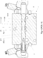
Figure 2 : shows the section of the spool of the summation element, in particular in the configuration that provides for the separation of the pumps, of the load-sensing signals and of the connection channels to the utilities dedicated to "travels", -
Figure 3 : shows the section of the spool of the summation element with the spool arranged so as to make a configuration with a complete combination of the circuits, i.e. of the pumps, of the connection channels with the travels and of the LS signals, -
Figure 4 : shows the section of the spool of the summation element with the spool arranged so as to make a configuration in which only the pumps are combined without connecting the load-sensing signals. -
Figure 5 : shows the prior art of an LS circuit with LS flow sharing directional valve with single LS pump. - As briefly mentioned above, the advantages of an LS flow-sharing system with LS pump are commonly known and can be summarized as follows:
- A first advantage is that the flow rate to the utility only depends on the spool stroke (the stand-by being set) and is independent of the load on the utility itself,
- A second advantage is that when the requirement from the various actuated utilities exceeds the maximum flow rate of the pump (saturation), the reduction of the flow rates to the various utilities is proportionally distributed among the utilities themselves,
- Finally, a further advantage is that the LS pump allows sending only the flow rate required (which becomes null, except for leaks, in case of no movement) with energy saving.
- A limitation of using a single LS pump is that if two utilities are actuated at different pressures, the entire flow rate delivered (sum of the flow rates required by the single spools) is delivered at the pressure of the utility with the highest pressure plus the stand-by value, i.e. also at the flow rate that actuates the utility at a lower pressure.
- Another limitation of using a single LS pump is in the case of slight high speed steers. With a single pump, the entire flow rate goes at the pressure of the track with the highest load, with the subsequent intervention of the torque limiter and abrupt slowdown.
- Using two LS pumps, as already described in the prior art mentioned above, allows recovering part of the above limitations, but nevertheless, in turn has other limitations:
- a first limitation might be that of a straight travel with the actuation of a third element: the machine steers,
- a second limitation may be linked to the request for a higher flow rate to the single pump,
- a third limitation corresponds to the situation where multiple utilities on the same LS pump may undergo a saturation condition.
- In all these cases, it would be convenient to combine the two pumps as if it were a single pump. Therefore, the possibility of combining/separating the two pumps with a suitable element electrically controlled as a function of inputs from the distributor itself but also from the rest of the machine, allows setting the circuit to the most convenient configuration, both from the energy and from the functional point of view.
- The circuit shown in
figure 1 describes the object of the invention. Overall, the circuit consists of two independent circuits separated by an intermediate summation element. - Each of said circuits:
- consists of an inlet side, indicated with
reference numerals element 3 serves for combining or separating said two groups of elements; - is delivered by the relative feeding delivering apparatus PA, PB, through high pressure lines P1, P2.
- The
intermediate element 3 comprises a number of components, connected to one another through conduits, pathways and connections, capable of connecting or separating the two groups of elements (E1, E2) (E3, E4) with therelative side intermediate summation element 3 is controlled by an electric or electro-hydraulic control in order to modify the LS circuit according to the working conditions of the machine tool, the latter comprising the hydraulic distributor operating according to the circuit diagram of the subject system 9. - It is also noted that the term elements, indicated with E1, E2, E3, E4, in system 9 in the hydraulics jargon refers to a number of sections which are representative of connections with a number of utilities. However, and for greater completeness, reference shall be made to patents
US7182097 orEP1628018 . - As mentioned above, E1 and E2 are arranged between the
inlet side 2 and thesummation element 3, while elements E3 and E4 are arranged between theinlet side 1 and thesummation element 3; such elements are then connected, through utilities A1, B1, A2, B2 ..., to the various utilities to be controlled. In particular, the two elements at the sides of the summation element 3 (in the specific example E2 and E3) will be taken as reference as those that need to be connected to, and thus deliver, the hydraulic motors in turn actuating the tracks to move the machine tool. - The valve circuit, indicated with reference numeral 9 and describing the operation of a hydraulic distributor, comprises:
- Two delivering channels or high pressure lines P1 and P2, respectively connectable to two delivering apparatus PA and PB; said apparatus PA, PB identify LS variable displacement pumps, which deliver
sides - A bleed channel 7, connected to a low pressure line, a tank T into which all bleeds flow,
- Two channels of the load-sensing signal, LS1 and LS2, coming from the two groups of elements E1 and E2 on one side and E3 and E4 on the other side; said channels have the function of sending the LS signals to the two respective delivering apparatus PA and PB, respectively, through respective connections,
- Two straight travel channels ST1 and ST2 coming from said two elements E2, E3 connectable to the tracks of the machine tool, on which said system 9 or distributor is installed; in particular, channels ST1, ST2 in the circuit in
figure 1 are downstream of the relative compensators (of the indicated elements) and upstream of the return to the relative spools (of the indicated elements), - a
suitable orifice 8 on one of channels ST1, ST2. - The summation/
separation element 3 is arranged between elements E1, E2, and E3, E4. - In detail, the flow rate delivered by the PB pump feeds, through the high-pressure line P1, the
inlet side 1, then elements E3 and E4 up to thesummation element 3. Vice versa, the LS signal coming from elements E3 and E4 reaches the PB pump through the LS2 connection. - The flow rate delivered by the PB pump feeds, through P2, the
inlet side 2, then elements E1 and E2 up to thesummation element 3. Vice versa, the LS signal coming from elements E1 and E2 reaches the PA pump through the LS1 connection. - The bleed of all elements and all valves is instead combined into channel T, which is then connected to the tank.
- The summation/
separation element 3 comprises at least one spool 4 whose movement, due to a proportional electro-hydraulic version controlled by a CPU based on the inputs from the various sensors already mentioned above, allows opening/closing connections between elements E1 and E2 and elements E3 and E4. - In detail, spool 4 has three positions and connecting channels; controlled by a proportional electro-hydraulic version, allows connecting or separating channels P1 and P2, channels ST1 and ST2 and signals LS1 and LS2 to/from each other.
- Moreover, in the positions of spool 4 in which LS1 and LS2 are separated, the spool itself connects LS1 to its own bleed channel b1 and LS2 to its own bleed channel b2 separate from each other. In the position in which LS1 and LS2 are connected, these are both connected to only one of the 2 bleeds while the other is isolated; in this way, the energy dissipation is conveniently reduced due to the cancellation of the flow rate bled from the relative isolated valve.
- The circuit thus formed, due to the presence of spool 4 of the
summation element 3, fits itself to work according to a logic dictated by the working conditions of one and/or both circuits, by the loads required and by the pressures in the circuits. - If only elements E2, E3 are actuated (which correspond to the two tracks and must be placed each in a different group with the relative pumps PA and PB), the channels for the two groups must remain separated to the benefit of the shift, especially in steering. Therefore, the summation element must be placed in the first position I in
Fig. 1 corresponding to the section inFig. 2 . - If the two tracks (which usually together require the whole flow rate delivered by the two pumps) plus a third utility are actuated, the two circuits with the relative pumps PA and PB must be combined in a single distributor, obtaining the complete union of the circuit, i.e. of the pump deliveries, of the connection channels between travels ST1 and ST2 and of the LS signals. This is because otherwise, the feeding rate of the third utility actuated would be subtracted only to one of the two elements E2, E3, causing an undesired steering of the excavator. Therefore, the summation element (3) must be placed in the second position II in
Fig. 3 . - In order to manage such a logic, it is necessary to be able to detect the actuation of the two travel elements and detect the actuation of any third section. The signals are then managed by a control unit, CPU processor, which in turn take action on the
summation element 3. - Provided that the first non-avoidable logic is dominant, the process can move on to a second level, as described hereinafter.
- If the flow rate required by each of the two single groups is less than the value which causes the saturation of the pump, it is convenient that the two groups remain separated so that each group works at its pressure. Otherwise, the full flow rate of the lower pressure group would rise to the pressure of the other group. Therefore, the summation element (3) must be placed in the first position I.
- If the flow rate required by each of the two single groups is close to or higher than the value which causes the saturation of the pump, it is convenient that the two groups remain separated so that each group works at its pressure. In fact, the combination would not create advantages of speed, since the two pumps are already almost to the maximum, on the contrary there would be the drawback of bringing both flow rates to the higher pressure, with the risk of triggering the torque limiter. Therefore, the summation element (3) must be placed in the first position I.
- The combination of the two groups has advantages when only one of the two groups is in saturation while the other requires little flow rate to its own pump, so as to exploit the capacity of the pump with low flow rate demand for feeding the group in saturation.
- However, the logic should be differentiated into two cases depending on the pressures involved.
- If the group in saturation has a pressure lower than that with a low flow rate (or not actuated). In this situation, only deliveries P1 and P2 of the pumps should be connected, but the load-sensing signals LS1 and LS2 should not. Due to natural lamination, this causes the flow rate passage from the high pressure group towards that in saturation and at a low pressure. However, without connecting the load-sensing signals LS1 and LS2, the pressure of the group in saturation keeps its low pressure, thus without the risk of switching to torque limitation and unnecessarily increasing the dissipated energy.
- Therefore, the summation element (3) must proportionally move towards the third position in
Fig. 1 , corresponding to the section inFig. 4 . - The proportionality of the control of spool 4 allows laminating, through the recesses of spool 4, the correct flow rate required by the group in saturation to come out of the saturation itself.
- If the group in saturation is that at high pressure, while the low pressure one requires little flow rate, the logic described above would not work. In such a situation, the
summation element 3 connects the two groups, as shown in the second position II. In other words, channels P1, P2 are connected, as are those of signals LS1, LS2. In doing so, the missing flow rate is provided to the group in saturation. The downside is that the pressure of the flow rate required by the other group is unnecessarily increased, although it has been defined as being little. - In order to manage such a logic, it is necessary to be able to detect the required flow rates, preferably by detecting the angle of the plate of the two pumps and the delivery pressure of the same two pumps.
- The circuit example in
figure 1 and the relative positions of spool 4 indicated inFigures 2 ,3 ,4 are exemplary and non-limiting. That is to say, they may be exchanged without affecting the indicated operation logic and the control will take action to position the spool in the proper configuration. - In practice, a hydraulic directional load-sensing flow-sharing system (9) is claimed, of the type comprising two independent circuits at the sides of an intermediate summation element (3).
- a. said two independent circuits being configured for connecting to a low pressure line (T) and respective load-sensing (LS) feeding apparatus (PA) and (PB) via respective high pressure lines (P1) and (P2) and load-sensing signal lines (LS1) and (LS2); each line (LS1) and (LS2) connectable to a respective bleed valve (b1) and (b2);
- b. said two independent circuits connectable to respective utilities via the connections (A1, A2, B1, B2, ...) placed on respective elements (E1, E2, ..., En) of said modular hydraulic system (9), and wherein (E2) and (E3) are two independent elements of the hydraulic system (9) served by said apparatus (PA) and (PB), respectively;
- c. said
intermediate summation element 3 is electrically controlled in order to keep the two independent circuits and the relative feeding apparatus PA, PB separates or combined; - More in detail, the
intermediate summation element 3 comprises a spool 4 having at least three positions/configurations I, II, III of which: - a. A first position I keeps the circuits and thereby the high-pressure lines P1 and P2 and the connection channels ST1 and ST2 of elements E2, E3, separated and independent, in particular downstream of the relative compensators and upstream of the return to the relative spools, it also keeps lines LS1 and LS2 separated, connecting each of said channels LS1, LS2 to its own bleed (b1) and bleed (b2) valve, acting as two distinct anti-saturation LS directional valves, each with its own LS pump and common only in bleed T,
- b. A second position II keeps the high pressure lines P1 and P2 and the connection channels ST1, ST2 of elements E2, E3 separated; channels LS1 and LS2, connecting them to a single bleed and isolating the other, work as a single anti-saturation LS directional valve delivered by the sum of the 2 LS pumps,
- c. A third position III only connects the high pressure lines P1 and P2 and keeps the channels of signals LS1 and LS2 separated and each connected to its own bleed valve b1 and b2; also keeping channels ST1, ST2 separated; in said condition, the valve acts as two distinct anti-saturation LS directional valves, each with its own LS pump, allowing some of the flow rate to pass from the highest pressure group to the lowest pressure one by pressure drop, adjusting such a flow rate by varying the opening of the passage opened by spool 4 by proportional control.
- The proportional passage between the three positions is carried out through an electric/electro-hydraulic proportional control managed by a CPU as a function of inputs detected on the machine and/or on the distributor by means of suitable sensors, as described in the document.
- The positions of spool are reversible and can be combined in different solutions. System 9 described is a valve body consisting of multiple sections, each serving multiple utilities and is also known by the term hydraulic distributor.
- In brief:
- In case of single shifting of the machine or if both groups are not in saturation, the proportional electro-hydraulic version of the
summation element 3 keeps spool 4 in position I. In this position, the delivery channels P1 and P2 are isolated as signals LS1 and LS2. In practice, the group formed by pump PB, theinlet side 2, elements E1 and E2 and the group formed by pump PA, theinlet side 1, elements E3 and E4, are separated from one another, forming 2 independent LS systems. Channel LS1 is only connected to its own bleed valve b1, and channel LS2 is only connected to its own bleed valve b2. Moreover, the straight travel is ensured by the fact that element E2 is delivered by its own pump PB and element E3 is delivered by its own pump PA and that these are separate. For this reason, the two channels ST1 and ST2, whose functionality has been described above, are isolated from each other. - In the case of actuation of the two travels of the machine tool, connected to said elements E2, E3, plus a third section or in case one of the two groups is in saturation and has a pressure higher than the other group not in saturation, the electro-hydraulic version moves spool 4 of the
summation element 3 to pos. II. In this position, the delivery channels P1, P2 are connected to each other, like signals LS1, LS2. In practice, it becomes a single LS system consisting of a single LS pump formed by PA plus PB which feeds a single directional valve formed by the twosides - If one of the two groups is in saturation and has a lower pressure than the other group not in saturation, the proportional electro-hydraulic version proportionally moves spool 4 of the
summation element 3 in the direction of POS. III. In so doing, it opens a passage between P1 and P2 whose area increases as the travel increases. In this position, channels LS1 and LS2 remain isolated so that the two groups continue to behave as two separate LS systems, each working at its own pressure. The connection between P1 and P2 through a suitable control area created by spool 4 in thesummation element 3 allows part of the flow rate of the pump not in saturation but at a higher pressure to feed, by simple pressure drop, the group in saturation but at a lower pressure. The value of this such a flow rate will depend on the difference of pressures between the two groups and on the opening of the passage between P1 and P2 as a function of the travel of spool 4 of thesummation element 3. Such a travel will be set by the CPU as a function of the various inputs coming in particular from the angular sensors of the oscillating plates of the LS pumps PA and PB and of the pressures of deliveries P1 and P2. - Since channels LS1 and LS2 are isolated from each other, each must keep the connection with its own bleed valve b1 and b2.
- In case of actuation of the travels, the CPU only allows pos. I or II. Position III is inhibited, thus channels ST1 and ST2 are kept isolated.
- Therefore, the
summation element 3 comprises a number of components, connected to one another through conduits, pathways and connections, capable of connecting or separating the two groups of elements with the relative side and LS pump. - The valve circuit describing a hydraulic distributor comprises:
- Two feeding channels P1 and P2, respectively connected to the two variable displacement LS pumps PA and PB, which respectively feed the sides, identified by
reference numerals - A bleed channel T, connected to a low pressure tank, into which all bleeds flow,
- Two channels of the load-sensing signal, LS1 and LS2, coming from the two groups of elements E1 and E2 on one side and E3 and E4 on the other side; said channels have the function of sending the LS signals to the two respective feeding apparatus PA and PB,
- Two straight travel channels ST1 and ST2 coming from the two elements E2, E3, which feed the two tracks of the machine tool (on which the distributor is installed), in particular, from the channels that in the circuit in
figure 1 are downstream of the relative compensators, - a
suitable orifice 8 on one of channels ST1 ST2. - The
summation element 3 is arranged between elements E1, E2, and E3, E4. - The
summation element 3 comprises at least one spool 4 having three positions with connecting channels; it is further controlled by a proportional electro-hydraulic version which allows connecting or separating channels P1 and P2, channels ST1 and ST2 and signals LS1 and LS2 to/from each other. - Moreover, in the positions of spool 4 in which LS1 and LS2 are separated, the spool itself connects LS1 to its own bleed valve b1 and LS2 to its own bleed valve b2, separate from each other. In the position in which LS1 and LS2 are connected, these are both connected to only one of the 2 bleeds while the other is isolated; in this way, the energy dissipation is conveniently reduced due to the cancellation of the flow rate bled from the relative isolated bleed valve.
- A further case is that in which the flow rate required by each of the two single groups is close to or higher than the value which causes the saturation of the pump. In this case, it is convenient that the two groups remain separated so that each group works at its pressure. In fact, the combination would not create advantages of speed, since the two pumps are already almost to the maximum, on the contrary there would be the drawback of bringing both flow rates to the higher pressure, with the risk of triggering the torque limiter and consequently reducing the machine speed rather than increasing it. Therefore, spool 4 of the
summation element 3 is kept in position I.
Claims (4)
- A hydraulic directional load-sensing flow-sharing system (9), of the type comprising two independent circuits at the sides of an intermediate summation element (3);a. said two independent circuits being configured for connecting to a low pressure line (T) and respective load-sensing (LS) feeding apparatus (PA) and (PB) via respective high pressure lines (P1) and (P2) and load-sensing signal lines (LS1) and (LS2); each line (LS1) and (LS2) connectable to a respective bleed valve (b1) and (b2);b. said two independent circuits connectable to respective utilities via the connections (A1, B1, A2, B2, A3, A4, B3, B4) placed on respective elements (E1, E2, E3, E4) of said modular hydraulic system (9), of which (E2) and (E3) are served by said apparatus (PA) and (PB), respectively;c. said intermediate summation element (3) can be controlled electrically to keep (P1) and (P2), channels (ST1) and (ST2) coming from said elements (E1, E2) and signals (LS1) and (LS2) separated, or keep them combined;the system (9) characterized in that said intermediate summation element (3) comprises a spool (4) having at least three positions/configurations (I, II, III) of which:a. a first position (I) keeps the circuits separated and independent, in particular the high pressure lines (P1) and (P2), channels ST1 and ST2 downstream of the relative compensators and upstream of the return to the relative spools of elements E2, E3, it also keeps lines (LS1) and (LS2) separated,b. A second position (II) combines the two circuits into one, combining the high pressure lines (P1) and (P2), channels ST1 and ST2 of elements (E2, E3); channels (LS1) and (LS2), connecting them to only one of the two bleeds,c. A third position (III) only connects the high pressure lines (P1) and (P2), keeping lines (LS1) and (LS2) separated; also keeping (ST1) and (ST2) of elements (E2, E3) separated.
- System (9), according to claim 1, characterized in that the proportional passage between the three positions (I, II, III) is managed by a proportional electric/electro-hydraulic drive controlled by a CPU according to inputs detected by sensors.
- System (9), according to claim 1, characterized in that the positions of the spool (4) are reversible and can be combined in different solutions.
- System (9), according to claim 1, characterized in that said third position (III) is activated when the independent circuit into saturation is the low pressure one.
Applications Claiming Priority (1)
| Application Number | Priority Date | Filing Date | Title |
|---|---|---|---|
| ITPR20150021 | 2015-04-02 |
Publications (2)
| Publication Number | Publication Date |
|---|---|
| EP3076028A1 true EP3076028A1 (en) | 2016-10-05 |
| EP3076028B1 EP3076028B1 (en) | 2023-07-05 |
Family
ID=53673216
Family Applications (1)
| Application Number | Title | Priority Date | Filing Date |
|---|---|---|---|
| EP16163600.6A Active EP3076028B1 (en) | 2015-04-02 | 2016-04-01 | Hydraulic load-sensing flow-sharing system |
Country Status (1)
| Country | Link |
|---|---|
| EP (1) | EP3076028B1 (en) |
Cited By (5)
| Publication number | Priority date | Publication date | Assignee | Title |
|---|---|---|---|---|
| US11143211B1 (en) | 2021-01-29 | 2021-10-12 | Cnh Industrial America Llc | System and method for controlling hydraulic fluid flow within a work vehicle |
| US11261582B1 (en) | 2021-01-29 | 2022-03-01 | Cnh Industrial America Llc | System and method for controlling hydraulic fluid flow within a work vehicle using flow control valves |
| US11313388B1 (en) | 2021-01-29 | 2022-04-26 | Cnh Industrial America Llc | System and method for controlling hydraulic fluid flow within a work vehicle |
| US11530524B2 (en) | 2021-01-29 | 2022-12-20 | Cnh Industrial America Llc | System and method for controlling hydraulic fluid flow within a work vehicle |
| US12523014B2 (en) | 2024-04-09 | 2026-01-13 | Cnh Industrial America Llc | System and method for controlling hydraulic fluid flow within a work vehicle |
Citations (9)
| Publication number | Priority date | Publication date | Assignee | Title |
|---|---|---|---|---|
| US5211014A (en) | 1991-01-15 | 1993-05-18 | Linde Aktiengesellschaft | Hydraulic drive system |
| JPH09210005A (en) * | 1996-02-02 | 1997-08-12 | Hitachi Constr Mach Co Ltd | Hydraulic drive for construction machinery |
| US20030205279A1 (en) * | 2002-05-02 | 2003-11-06 | Sauer-Danfoss (Nordborg) A/S | Hydraulic valve system |
| DE10255738A1 (en) * | 2002-11-07 | 2004-05-27 | Bosch Rexroth Ag | Double-circuit hydraulic system for controlling consumers of mobile equipment such as track equipment comprises two circuits interconnected by an interconnecting valve arrangement having two valve devices |
| EP1628018A1 (en) | 2004-08-17 | 2006-02-22 | Walvoil S.p.A. | Anti-saturation directional control valve composed of two or more sections with pressure selector compensators |
| US20060236688A1 (en) * | 2005-03-31 | 2006-10-26 | Nabtesco Corporation | Hydraulic circuit |
| WO2011114929A1 (en) * | 2010-03-18 | 2011-09-22 | ヤンマー株式会社 | Hydraulic circuit for working vehicle |
| EP2431538A1 (en) * | 2010-09-21 | 2012-03-21 | Kubota Corporation | Hydraulic system for working machine |
| DE102011111416A1 (en) * | 2011-08-23 | 2013-02-28 | Robert Bosch Gmbh | Energy exchange device for use in hydraulic drive system, has one sub-drive system and another sub-drive system, where each sub-drive system has hydraulic pump, discharge pressure control unit and multiple regulator control elements |
-
2016
- 2016-04-01 EP EP16163600.6A patent/EP3076028B1/en active Active
Patent Citations (10)
| Publication number | Priority date | Publication date | Assignee | Title |
|---|---|---|---|---|
| US5211014A (en) | 1991-01-15 | 1993-05-18 | Linde Aktiengesellschaft | Hydraulic drive system |
| JPH09210005A (en) * | 1996-02-02 | 1997-08-12 | Hitachi Constr Mach Co Ltd | Hydraulic drive for construction machinery |
| US20030205279A1 (en) * | 2002-05-02 | 2003-11-06 | Sauer-Danfoss (Nordborg) A/S | Hydraulic valve system |
| DE10255738A1 (en) * | 2002-11-07 | 2004-05-27 | Bosch Rexroth Ag | Double-circuit hydraulic system for controlling consumers of mobile equipment such as track equipment comprises two circuits interconnected by an interconnecting valve arrangement having two valve devices |
| EP1628018A1 (en) | 2004-08-17 | 2006-02-22 | Walvoil S.p.A. | Anti-saturation directional control valve composed of two or more sections with pressure selector compensators |
| US7182097B2 (en) | 2004-08-17 | 2007-02-27 | Walvoil S.P.A. | Anti-saturation directional control valve composed of two or more sections with pressure selector compensators |
| US20060236688A1 (en) * | 2005-03-31 | 2006-10-26 | Nabtesco Corporation | Hydraulic circuit |
| WO2011114929A1 (en) * | 2010-03-18 | 2011-09-22 | ヤンマー株式会社 | Hydraulic circuit for working vehicle |
| EP2431538A1 (en) * | 2010-09-21 | 2012-03-21 | Kubota Corporation | Hydraulic system for working machine |
| DE102011111416A1 (en) * | 2011-08-23 | 2013-02-28 | Robert Bosch Gmbh | Energy exchange device for use in hydraulic drive system, has one sub-drive system and another sub-drive system, where each sub-drive system has hydraulic pump, discharge pressure control unit and multiple regulator control elements |
Cited By (5)
| Publication number | Priority date | Publication date | Assignee | Title |
|---|---|---|---|---|
| US11143211B1 (en) | 2021-01-29 | 2021-10-12 | Cnh Industrial America Llc | System and method for controlling hydraulic fluid flow within a work vehicle |
| US11261582B1 (en) | 2021-01-29 | 2022-03-01 | Cnh Industrial America Llc | System and method for controlling hydraulic fluid flow within a work vehicle using flow control valves |
| US11313388B1 (en) | 2021-01-29 | 2022-04-26 | Cnh Industrial America Llc | System and method for controlling hydraulic fluid flow within a work vehicle |
| US11530524B2 (en) | 2021-01-29 | 2022-12-20 | Cnh Industrial America Llc | System and method for controlling hydraulic fluid flow within a work vehicle |
| US12523014B2 (en) | 2024-04-09 | 2026-01-13 | Cnh Industrial America Llc | System and method for controlling hydraulic fluid flow within a work vehicle |
Also Published As
| Publication number | Publication date |
|---|---|
| EP3076028B1 (en) | 2023-07-05 |
Similar Documents
| Publication | Publication Date | Title |
|---|---|---|
| EP3076028B1 (en) | Hydraulic load-sensing flow-sharing system | |
| US9874884B2 (en) | Valve block having a valve assembly | |
| CN103047207A (en) | Split and confluence valve group, hydraulic system, load-sensing hydraulic system and construction machinery | |
| KR101884012B1 (en) | Flow summation system for ontrolling a variable displacement hydraulic pump | |
| CN102549273A (en) | Electro-hydraulic controller | |
| US20130319561A1 (en) | Hydraulic Control Block And Hydraulic System | |
| KR20170065555A (en) | Directional control valve | |
| CN107917118A (en) | Composite control hydraulic circuit | |
| EP3078570B1 (en) | Hydraulic steering system | |
| EP3390841B1 (en) | Hydraulic valve device with multiple working sections with pump control system with by-pass line | |
| CN103452961A (en) | Open central control unit with constant and regulating pump | |
| CN106678111A (en) | Electrically-controlled multi-way valve | |
| CN211448991U (en) | controlling device | |
| CN110439057B (en) | Loader hydraulic system | |
| CN102562694B (en) | Load-sensing regulating type hydrostatic drive system | |
| US11614102B2 (en) | Pressure supply device | |
| US20070169473A1 (en) | Hydraulic circuit | |
| JP2013160382A (en) | Hydraulic control device | |
| EP3390842A1 (en) | Hydraulic valve device with multiple working sections with pump control system | |
| JP2006283784A (en) | Hydraulic circuit | |
| JP5435979B2 (en) | Hydrostatic drive system | |
| KR101648662B1 (en) | Hydraulic circuit for construction machine | |
| US20100018198A1 (en) | Valve arrangement | |
| EP3390843B1 (en) | Modular directional valve with two or more elements of mixed type | |
| GB2534518A (en) | Hydraulic drive system |
Legal Events
| Date | Code | Title | Description |
|---|---|---|---|
| PUAI | Public reference made under article 153(3) epc to a published international application that has entered the european phase |
Free format text: ORIGINAL CODE: 0009012 |
|
| AK | Designated contracting states |
Kind code of ref document: A1 Designated state(s): AL AT BE BG CH CY CZ DE DK EE ES FI FR GB GR HR HU IE IS IT LI LT LU LV MC MK MT NL NO PL PT RO RS SE SI SK SM TR |
|
| AX | Request for extension of the european patent |
Extension state: BA ME |
|
| STAA | Information on the status of an ep patent application or granted ep patent |
Free format text: STATUS: REQUEST FOR EXAMINATION WAS MADE |
|
| 17P | Request for examination filed |
Effective date: 20170405 |
|
| RBV | Designated contracting states (corrected) |
Designated state(s): AL AT BE BG CH CY CZ DE DK EE ES FI FR GB GR HR HU IE IS IT LI LT LU LV MC MK MT NL NO PL PT RO RS SE SI SK SM TR |
|
| STAA | Information on the status of an ep patent application or granted ep patent |
Free format text: STATUS: EXAMINATION IS IN PROGRESS |
|
| 17Q | First examination report despatched |
Effective date: 20200124 |
|
| RIC1 | Information provided on ipc code assigned before grant |
Ipc: E02F 9/22 20060101ALN20221205BHEP Ipc: F15B 11/17 20060101AFI20221205BHEP |
|
| RIC1 | Information provided on ipc code assigned before grant |
Ipc: E02F 9/22 20060101ALN20221219BHEP Ipc: F15B 11/17 20060101AFI20221219BHEP |
|
| GRAP | Despatch of communication of intention to grant a patent |
Free format text: ORIGINAL CODE: EPIDOSNIGR1 |
|
| STAA | Information on the status of an ep patent application or granted ep patent |
Free format text: STATUS: GRANT OF PATENT IS INTENDED |
|
| INTG | Intention to grant announced |
Effective date: 20230127 |
|
| GRAS | Grant fee paid |
Free format text: ORIGINAL CODE: EPIDOSNIGR3 |
|
| GRAA | (expected) grant |
Free format text: ORIGINAL CODE: 0009210 |
|
| STAA | Information on the status of an ep patent application or granted ep patent |
Free format text: STATUS: THE PATENT HAS BEEN GRANTED |
|
| AK | Designated contracting states |
Kind code of ref document: B1 Designated state(s): AL AT BE BG CH CY CZ DE DK EE ES FI FR GB GR HR HU IE IS IT LI LT LU LV MC MK MT NL NO PL PT RO RS SE SI SK SM TR |
|
| REG | Reference to a national code |
Ref country code: CH Ref legal event code: EP |
|
| REG | Reference to a national code |
Ref country code: AT Ref legal event code: REF Ref document number: 1585092 Country of ref document: AT Kind code of ref document: T Effective date: 20230715 |
|
| REG | Reference to a national code |
Ref country code: DE Ref legal event code: R096 Ref document number: 602016080758 Country of ref document: DE |
|
| P01 | Opt-out of the competence of the unified patent court (upc) registered |
Effective date: 20230622 |
|
| REG | Reference to a national code |
Ref country code: IE Ref legal event code: FG4D |
|
| REG | Reference to a national code |
Ref country code: LT Ref legal event code: MG9D |
|
| REG | Reference to a national code |
Ref country code: NL Ref legal event code: MP Effective date: 20230705 |
|
| REG | Reference to a national code |
Ref country code: AT Ref legal event code: MK05 Ref document number: 1585092 Country of ref document: AT Kind code of ref document: T Effective date: 20230705 |
|
| PG25 | Lapsed in a contracting state [announced via postgrant information from national office to epo] |
Ref country code: NL Free format text: LAPSE BECAUSE OF FAILURE TO SUBMIT A TRANSLATION OF THE DESCRIPTION OR TO PAY THE FEE WITHIN THE PRESCRIBED TIME-LIMIT Effective date: 20230705 |
|
| PG25 | Lapsed in a contracting state [announced via postgrant information from national office to epo] |
Ref country code: GR Free format text: LAPSE BECAUSE OF FAILURE TO SUBMIT A TRANSLATION OF THE DESCRIPTION OR TO PAY THE FEE WITHIN THE PRESCRIBED TIME-LIMIT Effective date: 20231006 |
|
| PG25 | Lapsed in a contracting state [announced via postgrant information from national office to epo] |
Ref country code: ES Free format text: LAPSE BECAUSE OF FAILURE TO SUBMIT A TRANSLATION OF THE DESCRIPTION OR TO PAY THE FEE WITHIN THE PRESCRIBED TIME-LIMIT Effective date: 20230705 |
|
| PG25 | Lapsed in a contracting state [announced via postgrant information from national office to epo] |
Ref country code: IS Free format text: LAPSE BECAUSE OF FAILURE TO SUBMIT A TRANSLATION OF THE DESCRIPTION OR TO PAY THE FEE WITHIN THE PRESCRIBED TIME-LIMIT Effective date: 20231105 |
|
| PG25 | Lapsed in a contracting state [announced via postgrant information from national office to epo] |
Ref country code: SE Free format text: LAPSE BECAUSE OF FAILURE TO SUBMIT A TRANSLATION OF THE DESCRIPTION OR TO PAY THE FEE WITHIN THE PRESCRIBED TIME-LIMIT Effective date: 20230705 Ref country code: RS Free format text: LAPSE BECAUSE OF FAILURE TO SUBMIT A TRANSLATION OF THE DESCRIPTION OR TO PAY THE FEE WITHIN THE PRESCRIBED TIME-LIMIT Effective date: 20230705 Ref country code: PT Free format text: LAPSE BECAUSE OF FAILURE TO SUBMIT A TRANSLATION OF THE DESCRIPTION OR TO PAY THE FEE WITHIN THE PRESCRIBED TIME-LIMIT Effective date: 20231106 Ref country code: NO Free format text: LAPSE BECAUSE OF FAILURE TO SUBMIT A TRANSLATION OF THE DESCRIPTION OR TO PAY THE FEE WITHIN THE PRESCRIBED TIME-LIMIT Effective date: 20231005 Ref country code: LV Free format text: LAPSE BECAUSE OF FAILURE TO SUBMIT A TRANSLATION OF THE DESCRIPTION OR TO PAY THE FEE WITHIN THE PRESCRIBED TIME-LIMIT Effective date: 20230705 Ref country code: LT Free format text: LAPSE BECAUSE OF FAILURE TO SUBMIT A TRANSLATION OF THE DESCRIPTION OR TO PAY THE FEE WITHIN THE PRESCRIBED TIME-LIMIT Effective date: 20230705 Ref country code: IS Free format text: LAPSE BECAUSE OF FAILURE TO SUBMIT A TRANSLATION OF THE DESCRIPTION OR TO PAY THE FEE WITHIN THE PRESCRIBED TIME-LIMIT Effective date: 20231105 Ref country code: HR Free format text: LAPSE BECAUSE OF FAILURE TO SUBMIT A TRANSLATION OF THE DESCRIPTION OR TO PAY THE FEE WITHIN THE PRESCRIBED TIME-LIMIT Effective date: 20230705 Ref country code: GR Free format text: LAPSE BECAUSE OF FAILURE TO SUBMIT A TRANSLATION OF THE DESCRIPTION OR TO PAY THE FEE WITHIN THE PRESCRIBED TIME-LIMIT Effective date: 20231006 Ref country code: FI Free format text: LAPSE BECAUSE OF FAILURE TO SUBMIT A TRANSLATION OF THE DESCRIPTION OR TO PAY THE FEE WITHIN THE PRESCRIBED TIME-LIMIT Effective date: 20230705 Ref country code: ES Free format text: LAPSE BECAUSE OF FAILURE TO SUBMIT A TRANSLATION OF THE DESCRIPTION OR TO PAY THE FEE WITHIN THE PRESCRIBED TIME-LIMIT Effective date: 20230705 Ref country code: AT Free format text: LAPSE BECAUSE OF FAILURE TO SUBMIT A TRANSLATION OF THE DESCRIPTION OR TO PAY THE FEE WITHIN THE PRESCRIBED TIME-LIMIT Effective date: 20230705 |
|
| PG25 | Lapsed in a contracting state [announced via postgrant information from national office to epo] |
Ref country code: PL Free format text: LAPSE BECAUSE OF FAILURE TO SUBMIT A TRANSLATION OF THE DESCRIPTION OR TO PAY THE FEE WITHIN THE PRESCRIBED TIME-LIMIT Effective date: 20230705 |
|
| REG | Reference to a national code |
Ref country code: DE Ref legal event code: R097 Ref document number: 602016080758 Country of ref document: DE |
|
| PG25 | Lapsed in a contracting state [announced via postgrant information from national office to epo] |
Ref country code: SM Free format text: LAPSE BECAUSE OF FAILURE TO SUBMIT A TRANSLATION OF THE DESCRIPTION OR TO PAY THE FEE WITHIN THE PRESCRIBED TIME-LIMIT Effective date: 20230705 Ref country code: RO Free format text: LAPSE BECAUSE OF FAILURE TO SUBMIT A TRANSLATION OF THE DESCRIPTION OR TO PAY THE FEE WITHIN THE PRESCRIBED TIME-LIMIT Effective date: 20230705 Ref country code: EE Free format text: LAPSE BECAUSE OF FAILURE TO SUBMIT A TRANSLATION OF THE DESCRIPTION OR TO PAY THE FEE WITHIN THE PRESCRIBED TIME-LIMIT Effective date: 20230705 Ref country code: DK Free format text: LAPSE BECAUSE OF FAILURE TO SUBMIT A TRANSLATION OF THE DESCRIPTION OR TO PAY THE FEE WITHIN THE PRESCRIBED TIME-LIMIT Effective date: 20230705 Ref country code: CZ Free format text: LAPSE BECAUSE OF FAILURE TO SUBMIT A TRANSLATION OF THE DESCRIPTION OR TO PAY THE FEE WITHIN THE PRESCRIBED TIME-LIMIT Effective date: 20230705 Ref country code: SK Free format text: LAPSE BECAUSE OF FAILURE TO SUBMIT A TRANSLATION OF THE DESCRIPTION OR TO PAY THE FEE WITHIN THE PRESCRIBED TIME-LIMIT Effective date: 20230705 |
|
| PLBE | No opposition filed within time limit |
Free format text: ORIGINAL CODE: 0009261 |
|
| STAA | Information on the status of an ep patent application or granted ep patent |
Free format text: STATUS: NO OPPOSITION FILED WITHIN TIME LIMIT |
|
| 26N | No opposition filed |
Effective date: 20240408 |
|
| PG25 | Lapsed in a contracting state [announced via postgrant information from national office to epo] |
Ref country code: SI Free format text: LAPSE BECAUSE OF FAILURE TO SUBMIT A TRANSLATION OF THE DESCRIPTION OR TO PAY THE FEE WITHIN THE PRESCRIBED TIME-LIMIT Effective date: 20230705 |
|
| PG25 | Lapsed in a contracting state [announced via postgrant information from national office to epo] |
Ref country code: BG Free format text: LAPSE BECAUSE OF FAILURE TO SUBMIT A TRANSLATION OF THE DESCRIPTION OR TO PAY THE FEE WITHIN THE PRESCRIBED TIME-LIMIT Effective date: 20230705 |
|
| PG25 | Lapsed in a contracting state [announced via postgrant information from national office to epo] |
Ref country code: MC Free format text: LAPSE BECAUSE OF FAILURE TO SUBMIT A TRANSLATION OF THE DESCRIPTION OR TO PAY THE FEE WITHIN THE PRESCRIBED TIME-LIMIT Effective date: 20230705 |
|
| PG25 | Lapsed in a contracting state [announced via postgrant information from national office to epo] |
Ref country code: MC Free format text: LAPSE BECAUSE OF FAILURE TO SUBMIT A TRANSLATION OF THE DESCRIPTION OR TO PAY THE FEE WITHIN THE PRESCRIBED TIME-LIMIT Effective date: 20230705 Ref country code: BG Free format text: LAPSE BECAUSE OF FAILURE TO SUBMIT A TRANSLATION OF THE DESCRIPTION OR TO PAY THE FEE WITHIN THE PRESCRIBED TIME-LIMIT Effective date: 20230705 |
|
| REG | Reference to a national code |
Ref country code: CH Ref legal event code: PL |
|
| PG25 | Lapsed in a contracting state [announced via postgrant information from national office to epo] |
Ref country code: LU Free format text: LAPSE BECAUSE OF NON-PAYMENT OF DUE FEES Effective date: 20240401 |
|
| GBPC | Gb: european patent ceased through non-payment of renewal fee |
Effective date: 20240401 |
|
| REG | Reference to a national code |
Ref country code: BE Ref legal event code: MM Effective date: 20240430 |
|
| PG25 | Lapsed in a contracting state [announced via postgrant information from national office to epo] |
Ref country code: LU Free format text: LAPSE BECAUSE OF NON-PAYMENT OF DUE FEES Effective date: 20240401 |
|
| PG25 | Lapsed in a contracting state [announced via postgrant information from national office to epo] |
Ref country code: BE Free format text: LAPSE BECAUSE OF NON-PAYMENT OF DUE FEES Effective date: 20240430 |
|
| PG25 | Lapsed in a contracting state [announced via postgrant information from national office to epo] |
Ref country code: GB Free format text: LAPSE BECAUSE OF NON-PAYMENT OF DUE FEES Effective date: 20240401 |
|
| PG25 | Lapsed in a contracting state [announced via postgrant information from national office to epo] |
Ref country code: GB Free format text: LAPSE BECAUSE OF NON-PAYMENT OF DUE FEES Effective date: 20240401 Ref country code: BE Free format text: LAPSE BECAUSE OF NON-PAYMENT OF DUE FEES Effective date: 20240430 Ref country code: CH Free format text: LAPSE BECAUSE OF NON-PAYMENT OF DUE FEES Effective date: 20240430 |
|
| PG25 | Lapsed in a contracting state [announced via postgrant information from national office to epo] |
Ref country code: IE Free format text: LAPSE BECAUSE OF NON-PAYMENT OF DUE FEES Effective date: 20240401 |
|
| PGFP | Annual fee paid to national office [announced via postgrant information from national office to epo] |
Ref country code: DE Payment date: 20250422 Year of fee payment: 10 |
|
| PGFP | Annual fee paid to national office [announced via postgrant information from national office to epo] |
Ref country code: IT Payment date: 20250429 Year of fee payment: 10 |
|
| PGFP | Annual fee paid to national office [announced via postgrant information from national office to epo] |
Ref country code: FR Payment date: 20250425 Year of fee payment: 10 |
|
| PG25 | Lapsed in a contracting state [announced via postgrant information from national office to epo] |
Ref country code: CY Free format text: LAPSE BECAUSE OF FAILURE TO SUBMIT A TRANSLATION OF THE DESCRIPTION OR TO PAY THE FEE WITHIN THE PRESCRIBED TIME-LIMIT; INVALID AB INITIO Effective date: 20160401 |
|
| PG25 | Lapsed in a contracting state [announced via postgrant information from national office to epo] |
Ref country code: HU Free format text: LAPSE BECAUSE OF FAILURE TO SUBMIT A TRANSLATION OF THE DESCRIPTION OR TO PAY THE FEE WITHIN THE PRESCRIBED TIME-LIMIT; INVALID AB INITIO Effective date: 20160401 |
|
| PG25 | Lapsed in a contracting state [announced via postgrant information from national office to epo] |
Ref country code: TR Free format text: LAPSE BECAUSE OF FAILURE TO SUBMIT A TRANSLATION OF THE DESCRIPTION OR TO PAY THE FEE WITHIN THE PRESCRIBED TIME-LIMIT Effective date: 20230705 |