EP3075673A1 - A protective cover for a container - Google Patents
A protective cover for a container Download PDFInfo
- Publication number
- EP3075673A1 EP3075673A1 EP16161576.0A EP16161576A EP3075673A1 EP 3075673 A1 EP3075673 A1 EP 3075673A1 EP 16161576 A EP16161576 A EP 16161576A EP 3075673 A1 EP3075673 A1 EP 3075673A1
- Authority
- EP
- European Patent Office
- Prior art keywords
- cover
- recess
- floor
- container
- protective cover
- Prior art date
- Legal status (The legal status is an assumption and is not a legal conclusion. Google has not performed a legal analysis and makes no representation as to the accuracy of the status listed.)
- Withdrawn
Links
- 230000001681 protective effect Effects 0.000 title claims abstract description 21
- 229920001131 Pulp (paper) Polymers 0.000 claims description 4
- 239000003973 paint Substances 0.000 abstract description 8
- ATJFFYVFTNAWJD-UHFFFAOYSA-N Tin Chemical compound [Sn] ATJFFYVFTNAWJD-UHFFFAOYSA-N 0.000 abstract description 7
- 230000009977 dual effect Effects 0.000 abstract 1
- 229920003023 plastic Polymers 0.000 description 4
- 238000004806 packaging method and process Methods 0.000 description 3
- 239000004033 plastic Substances 0.000 description 3
- 235000010627 Phaseolus vulgaris Nutrition 0.000 description 2
- 244000046052 Phaseolus vulgaris Species 0.000 description 2
- 238000000034 method Methods 0.000 description 2
- 235000015096 spirit Nutrition 0.000 description 2
- 230000000694 effects Effects 0.000 description 1
- 238000001746 injection moulding Methods 0.000 description 1
- 238000004519 manufacturing process Methods 0.000 description 1
- 239000000463 material Substances 0.000 description 1
- 238000012986 modification Methods 0.000 description 1
- 230000004048 modification Effects 0.000 description 1
- 238000000465 moulding Methods 0.000 description 1
- 239000002994 raw material Substances 0.000 description 1
- 235000014214 soft drink Nutrition 0.000 description 1
- 239000000243 solution Substances 0.000 description 1
- 238000005728 strengthening Methods 0.000 description 1
Images

Classifications
-
- B—PERFORMING OPERATIONS; TRANSPORTING
- B65—CONVEYING; PACKING; STORING; HANDLING THIN OR FILAMENTARY MATERIAL
- B65D—CONTAINERS FOR STORAGE OR TRANSPORT OF ARTICLES OR MATERIALS, e.g. BAGS, BARRELS, BOTTLES, BOXES, CANS, CARTONS, CRATES, DRUMS, JARS, TANKS, HOPPERS, FORWARDING CONTAINERS; ACCESSORIES, CLOSURES, OR FITTINGS THEREFOR; PACKAGING ELEMENTS; PACKAGES
- B65D5/00—Rigid or semi-rigid containers of polygonal cross-section, e.g. boxes, cartons or trays, formed by folding or erecting one or more blanks made of paper
- B65D5/42—Details of containers or of foldable or erectable container blanks
- B65D5/44—Integral, inserted or attached portions forming internal or external fittings
- B65D5/50—Internal supporting or protecting elements for contents
- B65D5/5028—Elements formed separately from the container body
- B65D5/5035—Paper elements
- B65D5/5069—Capping elements, i.e. elements which are located onto one or more ends of the contents, before the contents are inserted into the package
-
- B—PERFORMING OPERATIONS; TRANSPORTING
- B65—CONVEYING; PACKING; STORING; HANDLING THIN OR FILAMENTARY MATERIAL
- B65D—CONTAINERS FOR STORAGE OR TRANSPORT OF ARTICLES OR MATERIALS, e.g. BAGS, BARRELS, BOTTLES, BOXES, CANS, CARTONS, CRATES, DRUMS, JARS, TANKS, HOPPERS, FORWARDING CONTAINERS; ACCESSORIES, CLOSURES, OR FITTINGS THEREFOR; PACKAGING ELEMENTS; PACKAGES
- B65D81/00—Containers, packaging elements, or packages, for contents presenting particular transport or storage problems, or adapted to be used for non-packaging purposes after removal of contents
- B65D81/02—Containers, packaging elements, or packages, for contents presenting particular transport or storage problems, or adapted to be used for non-packaging purposes after removal of contents specially adapted to protect contents from mechanical damage
- B65D81/05—Containers, packaging elements, or packages, for contents presenting particular transport or storage problems, or adapted to be used for non-packaging purposes after removal of contents specially adapted to protect contents from mechanical damage maintaining contents at spaced relation from package walls, or from other contents
- B65D81/053—Corner, edge or end protectors
- B65D81/058—Protectors contacting five surfaces of the packaged article, e.g. five-sided end protectors
-
- B—PERFORMING OPERATIONS; TRANSPORTING
- B65—CONVEYING; PACKING; STORING; HANDLING THIN OR FILAMENTARY MATERIAL
- B65D—CONTAINERS FOR STORAGE OR TRANSPORT OF ARTICLES OR MATERIALS, e.g. BAGS, BARRELS, BOTTLES, BOXES, CANS, CARTONS, CRATES, DRUMS, JARS, TANKS, HOPPERS, FORWARDING CONTAINERS; ACCESSORIES, CLOSURES, OR FITTINGS THEREFOR; PACKAGING ELEMENTS; PACKAGES
- B65D81/00—Containers, packaging elements, or packages, for contents presenting particular transport or storage problems, or adapted to be used for non-packaging purposes after removal of contents
- B65D81/02—Containers, packaging elements, or packages, for contents presenting particular transport or storage problems, or adapted to be used for non-packaging purposes after removal of contents specially adapted to protect contents from mechanical damage
- B65D81/025—Containers made of sheet-like material and having a shape to accommodate contents
Definitions
- the present invention is directed to the field of protective covers. More particularly the present invention is a temporary cover which may be fitted over an end of a container so as to protect the container from damage during transportation and handling.
- Containers which are used for the packaging of consumer goods can be vulnerable to damage during transportation from the source of manufacture to the point of sale. Such damage may not greatly reduce the value of the goods contained therein when the container is holding relatively low value goods such as in the case of a soft drink can or tin of baked beans, for example. However, this kind of damage is far more undesirable when the container contains a higher value product such as in the case of a paint tin holding an expensive paint or a tubular presentation cylinder for a bottle of spirits, for example.
- lower value items such as the drinks cans and baked bean tins are placed in a cardboard tray which then has a layer of transparent plastic shrink wrapped over the tray and the items therein to protect against the ingress of dirt and other foreign objects.
- the relatively thin cardboard tray protects one end of each item against impact damage to a limited extent, but the other end of each item is not protected by the layer of plastic.
- to protect these lower value items to any greater extent is not justified by the relatively low cost of the goods in the containers.
- a protective cover for a container comprising a recess for housing an end of the container therein, wherein the recess includes a recess floor and the cover further comprises a plurality of channels extending in a radial direction from the centre of the recess, the channels dividing the floor into a plurality of floor segments.
- Each floor segment may include a first floor portion lying in a substantially horizontal first plane and a second floor portion lying in a substantially horizontal second plane which is vertically spaced from the first plane.
- the second floor portion may be located radially outwards of the first floor portion.
- the cover may further comprise an outer portion which surrounds the recess, and the plurality of channels may extend radially from the centre of the recess into the outer portion. Consequently, each channel has a first depth proximate the first floor portion of each floor segment, and a second depth proximate the outer portion, wherein the second depth is greater than the first depth.
- the outer portion may have a substantially planar upper surface, and the cover may further comprise a plurality of notches in the upper surface, each notch being located where one of the plurality of channels extends into the outer portion. Each notch creates a section in the outer portion which lies at a lower height than that of the upper surface.
- the outer portion may be substantially square, and there may be a notch located substantially centrally in each of the four sides of the outer portion.
- the outer portion may have an outer edge and the cover may further comprise a lip portion which extends around the cover in a downward direction from the outer edge.
- the cover may comprise eight channels equidistantly spaced around the recess and dividing the recess floor into eight corresponding floor segments.
- the cover may comprise a base on a reverse side of the cover from the recess, the base comprising a plurality of radially extending support members, wherein each support member is formed from an underside of a corresponding channel.
- the recess may be substantially circular.
- the cover may be manufactured from moulded paper pulp.
- a container comprising at least one cover according to the first aspect of the invention, wherein an end of the container is located in the recess of the at least one cover.
- the container may comprise first and second covers according to the first aspect of the invention, wherein a first end of the container is located in the recess of the first cover, and a second end of the container is located in the recess of the second cover.
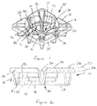
- a protective cover in accordance with the present invention is shown in Figures 1 and 2 . Whilst the cover can be adapted for use with containers of various shapes, the preferred embodiment shown here is intended to protect cylindrical containers such as paint tins and tubular presentation packaging, for example.
- the cover generally designated 10, has a recess 12 for housing an end of a container therein.
- the recess 12 includes a recess floor 14, and a plurality of channels 16 are provided in the recess floor to provide rigidity to the cover 10 as a whole.
- the channels 16 extend outwards in a radial direction from a centre 18 of the recess and thus divide the floor 14 into a plurality of floor segments 20.
- the channels 16 are preferably equidistantly spaced in the circumferential direction about the recess centre 18 such the channels divide the floor 14 into a plurality of identically sized floor segments which are generally triangular in shape.
- the number of channels 16 and resultant floor segments 20 can be varied depending on the requirements or application of the cover 10, but in the preferred embodiment there are eight channels and hence eight floor segments.
- each floor segment 20 includes a first floor portion 22 lying in a substantially horizontal first plane P1 and a second floor portion 24 lying in a substantially horizontal second plane P2 which is vertically spaced from the first plane by a predetermined distance X.
- the second floor portions 24 are located radially outwards of their respective first floor portions 22.
- the cover may itself be generally cylindrical in shape when used with cylindrical containers of the type discussed above. However, as shown in the preferred embodiment the cover 10 may also be generally square in shape such that there is an outer portion 26 which surrounds the recess 12 and extends radially outwards from the recess 12.
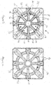
- the plurality of channels 16 may extend radially from the recess centre 18 into the outer portion, as can be best seen in Figure 3 .
- each channel 16 would then have a first depth D1 as it passes through the first floor portion 22 of each floor segment 20, and a second depth D2 where it enters the outer portion 26.
- the channel will have a third depth D3 where it passes through the second floor portion 24.
- the second depth D2 is greater than the first depth D1 and, where present, the third depth D3 is greater than the first depth D1 but less than the second depth D2.
- the outer portion 26 may have a substantially planar upper surface 28, and the cover 10 may further comprise a plurality of notches 30 in the upper surface 28.
- Each notch 30 is located where one of the plurality of channels 16 extends into the outer portion 26.
- the upper surface 28 lies in a third plane P3 and each notch 30 creates a section in the outer portion 26 which lies in a fourth plane P4 which lies below the third plane P3.
- the notches 30 may be located substantially centrally in each of the four sides of the square, as seen best in Figure 3 .
- the outer portion 26 may have an outer edge 32 and the cover 10 may further comprise a lip portion 34 which extends around the cover in a downward direction from the outer edge 32. Where present, the lip portion 34 provides additional strengthening and rigidity for the cover 10.
- the cover 10 has a base 36 on the reverse side of the cover from the recess 12, and this base is best seen in Figure 4 .
- the base may comprise a substantially flat support surface but in the preferred embodiment shown the base 36 has a plurality of radially extending support members, or crush pads, 38 upon which the cover can rest.
- the support members 38 are each formed from an underside of a corresponding channel 16, and in use not only provide stability to the cover and container by are also intended to absorb impacts and protect the container from damage.
- Figure 5 shows an example of the cover in use, where a container such as a paint tin 40 has both ends located in the recess 12 of one of a pair of covers 10.
- the covers 10 can house containers of different sizes in the manner described above.
- the paint tin 40 shown here is a 5 litre tin, and so each end of the tin is supported on the second floor portions 24 of the floor segments 20 within the recess 12.
- the cover may be formed from a suitable plastics material using injection moulding or a similar known technique. However, it is preferably formed from moulded paper pulp again using a known technique for moulding paper pulp. This latter form means that the cover may be recycled relatively easily once it has serviced its purpose during the transportation of the product.
- the protective cover according to the present invention provides a relatively low cost and environmentally friendly solution to protecting containers of valuable goods or products during transportation in particular.
- the arrangement of radially extending channels provides strength to the cover without having to use an excessive amount of raw material.
- the base of the cover is made up of support members formed by the undersides of these channels, the covers themselves are also easy to store and transport as they can be stacked up with the support members fitting inside the corresponding channels of the cover immediately underneath.
- each floor segment in the recess is split into the first and second floor portions the cover can be used for two different sizes of container, thereby avoiding the costs associated with having to produce two separate covers.
- the recess in the preferred embodiment of the invention is generally cylindrical so as to receive containers of the same shape
- the recess could be provided with other shapes for other containers.
- the recess may be square or rectangular in order to protect the ends of containers having those shapes.
- the cover preferably includes an outer portion outwards of the recess and the channels in the recess preferably extend into that outer portion
- the cover may be formed without the outer portion and/or its associated lip.
- the outer portion may be present to further improve the rigidity of the cover but the channels may not extend into the outer portion.
- the present invention is not limited to an arrangement in which the notches are present in the upper surface of the outer portion.
- the cover may be provided with more or less than eight channels and associated floor segments.
Landscapes
- Engineering & Computer Science (AREA)
- Mechanical Engineering (AREA)
- Details Of Rigid Or Semi-Rigid Containers (AREA)
Abstract
The invention relates to a protective cover for a container, such as a paint tin. The cover (10) comprises a recess (12) for housing an end of a container. The recess (12) includes a recess floor (14) and a plurality of channels (16) extending in a radial direction from its centre. The channels (16) divide the floor (14) into a plurality of triangular floor segments (20). Each segment (20) may be arranged to have two floor portions (22, 24) lying in vertically spaced planes (P1, P2). The outer (higher) floor portion (24) is located radially outwards of the inner (lower) floor portion (22). The cover (10) may therefore serve the dual purpose of protection containers of different diameters.
Description
- The present invention is directed to the field of protective covers. More particularly the present invention is a temporary cover which may be fitted over an end of a container so as to protect the container from damage during transportation and handling.
- Containers which are used for the packaging of consumer goods can be vulnerable to damage during transportation from the source of manufacture to the point of sale. Such damage may not greatly reduce the value of the goods contained therein when the container is holding relatively low value goods such as in the case of a soft drink can or tin of baked beans, for example. However, this kind of damage is far more undesirable when the container contains a higher value product such as in the case of a paint tin holding an expensive paint or a tubular presentation cylinder for a bottle of spirits, for example.
- Generally, lower value items such as the drinks cans and baked bean tins are placed in a cardboard tray which then has a layer of transparent plastic shrink wrapped over the tray and the items therein to protect against the ingress of dirt and other foreign objects. Thus the relatively thin cardboard tray protects one end of each item against impact damage to a limited extent, but the other end of each item is not protected by the layer of plastic. However, to protect these lower value items to any greater extent is not justified by the relatively low cost of the goods in the containers.
- The larger, higher value items such as paint tins and presentation packaging for spirits are transported in a similar manner to that described above for the lower value items, albeit on a larger scale. Therefore, instead of a cardboard tray these higher value items are typically stacked on wooden pallets with a layer of plastic then wrapped over the pallets and the items thereon. Whilst the pallets are far more rigid than the cardboard trays the items stacked on the pallets are still susceptible to damage during transportation.
- Given that damage to the containers in which these higher value goods are held can have a significant effect on the value of those goods, it would be advantageous to provide such containers with a protective arrangement which reduces the likelihood of damage being caused to the individual containers during transportation.
- According to a first aspect of the invention there is provided a protective cover for a container, the cover comprising a recess for housing an end of the container therein, wherein the recess includes a recess floor and the cover further comprises a plurality of channels extending in a radial direction from the centre of the recess, the channels dividing the floor into a plurality of floor segments.
- Each floor segment may include a first floor portion lying in a substantially horizontal first plane and a second floor portion lying in a substantially horizontal second plane which is vertically spaced from the first plane. The second floor portion may be located radially outwards of the first floor portion. In this way the cover can house container ends of two different diameters, where a container end having a small diameter would lie upon the first floor portion of each floor segment, and a container end of a larger diameter would lie upon the second floor portion of each floor segment.
- The cover may further comprise an outer portion which surrounds the recess, and the plurality of channels may extend radially from the centre of the recess into the outer portion. Consequently, each channel has a first depth proximate the first floor portion of each floor segment, and a second depth proximate the outer portion, wherein the second depth is greater than the first depth.
- The outer portion may have a substantially planar upper surface, and the cover may further comprise a plurality of notches in the upper surface, each notch being located where one of the plurality of channels extends into the outer portion. Each notch creates a section in the outer portion which lies at a lower height than that of the upper surface. The outer portion may be substantially square, and there may be a notch located substantially centrally in each of the four sides of the outer portion.
- The outer portion may have an outer edge and the cover may further comprise a lip portion which extends around the cover in a downward direction from the outer edge.
- The cover may comprise eight channels equidistantly spaced around the recess and dividing the recess floor into eight corresponding floor segments.
- The cover may comprise a base on a reverse side of the cover from the recess, the base comprising a plurality of radially extending support members, wherein each support member is formed from an underside of a corresponding channel.
- The recess may be substantially circular.
- The cover may be manufactured from moulded paper pulp.
- According to a second aspect of the invention there is provided a container comprising at least one cover according to the first aspect of the invention, wherein an end of the container is located in the recess of the at least one cover.
- The container may comprise first and second covers according to the first aspect of the invention, wherein a first end of the container is located in the recess of the first cover, and a second end of the container is located in the recess of the second cover.
- A preferred embodiment of the present invention will now be described, by way of example only, with reference to the following drawings:
-
Figure 1 is a perspective view of a protective cover for a container; -
Figure 2 is a side view of the cover shown inFigure 1 ; -
Figures 3 and 4 are top and bottom views, respectively, of the cover shown inFigure 1 ; and -
Figure 5 shows a container protected by a pair of covers which are each identical to that shown inFigures 1-4 . - A protective cover in accordance with the present invention is shown in
Figures 1 and 2 . Whilst the cover can be adapted for use with containers of various shapes, the preferred embodiment shown here is intended to protect cylindrical containers such as paint tins and tubular presentation packaging, for example. The cover, generally designated 10, has arecess 12 for housing an end of a container therein. Therecess 12 includes arecess floor 14, and a plurality ofchannels 16 are provided in the recess floor to provide rigidity to thecover 10 as a whole. Thechannels 16 extend outwards in a radial direction from acentre 18 of the recess and thus divide thefloor 14 into a plurality offloor segments 20. Thechannels 16 are preferably equidistantly spaced in the circumferential direction about therecess centre 18 such the channels divide thefloor 14 into a plurality of identically sized floor segments which are generally triangular in shape. The number ofchannels 16 andresultant floor segments 20 can be varied depending on the requirements or application of thecover 10, but in the preferred embodiment there are eight channels and hence eight floor segments. - The cover may be provided with the intention of protecting only one size of container. However, in the preferred embodiment the cover is adapted so that it can be used in conjunction with two containers having different sizes. The containers could be, for example, paint tins which have either a 2.5 or 5 litre volume and different diameters as a result. In this example, each
floor segment 20 includes afirst floor portion 22 lying in a substantially horizontal first plane P1 and asecond floor portion 24 lying in a substantially horizontal second plane P2 which is vertically spaced from the first plane by a predetermined distance X. Thesecond floor portions 24 are located radially outwards of their respectivefirst floor portions 22. - The cover may itself be generally cylindrical in shape when used with cylindrical containers of the type discussed above. However, as shown in the preferred embodiment the
cover 10 may also be generally square in shape such that there is anouter portion 26 which surrounds therecess 12 and extends radially outwards from therecess 12. The plurality ofchannels 16 may extend radially from therecess centre 18 into the outer portion, as can be best seen inFigure 3 . In such a case, eachchannel 16 would then have a first depth D1 as it passes through thefirst floor portion 22 of eachfloor segment 20, and a second depth D2 where it enters theouter portion 26. In the instance where thesegments 20 have first andsecond floor portions second floor portion 24. The second depth D2 is greater than the first depth D1 and, where present, the third depth D3 is greater than the first depth D1 but less than the second depth D2. - As best seen in
Figures 1 and 2 , theouter portion 26 may have a substantially planarupper surface 28, and thecover 10 may further comprise a plurality ofnotches 30 in theupper surface 28. Eachnotch 30 is located where one of the plurality ofchannels 16 extends into theouter portion 26. Theupper surface 28 lies in a third plane P3 and eachnotch 30 creates a section in theouter portion 26 which lies in a fourth plane P4 which lies below the third plane P3. Where theouter portion 26 results in acover 10 which is substantially square, thenotches 30 may be located substantially centrally in each of the four sides of the square, as seen best inFigure 3 . Thesenotches 30 provide extra strength to theouter portion 26 of the cover, increasing the stability of the cover and hence the container which the cover protects. - As best seen in
Figure 1 , theouter portion 26 may have anouter edge 32 and thecover 10 may further comprise alip portion 34 which extends around the cover in a downward direction from theouter edge 32. Where present, thelip portion 34 provides additional strengthening and rigidity for thecover 10. - The
cover 10 has abase 36 on the reverse side of the cover from therecess 12, and this base is best seen inFigure 4 . The base may comprise a substantially flat support surface but in the preferred embodiment shown thebase 36 has a plurality of radially extending support members, or crush pads, 38 upon which the cover can rest. Thesupport members 38 are each formed from an underside of a correspondingchannel 16, and in use not only provide stability to the cover and container by are also intended to absorb impacts and protect the container from damage. -
Figure 5 shows an example of the cover in use, where a container such as apaint tin 40 has both ends located in therecess 12 of one of a pair ofcovers 10. In this example, thecovers 10 can house containers of different sizes in the manner described above. Thepaint tin 40 shown here is a 5 litre tin, and so each end of the tin is supported on thesecond floor portions 24 of thefloor segments 20 within therecess 12. - The cover may be formed from a suitable plastics material using injection moulding or a similar known technique. However, it is preferably formed from moulded paper pulp again using a known technique for moulding paper pulp. This latter form means that the cover may be recycled relatively easily once it has serviced its purpose during the transportation of the product.
- The protective cover according to the present invention provides a relatively low cost and environmentally friendly solution to protecting containers of valuable goods or products during transportation in particular. The arrangement of radially extending channels provides strength to the cover without having to use an excessive amount of raw material. Where the base of the cover is made up of support members formed by the undersides of these channels, the covers themselves are also easy to store and transport as they can be stacked up with the support members fitting inside the corresponding channels of the cover immediately underneath.
- If each floor segment in the recess is split into the first and second floor portions the cover can be used for two different sizes of container, thereby avoiding the costs associated with having to produce two separate covers.
- Whilst the recess in the preferred embodiment of the invention is generally cylindrical so as to receive containers of the same shape, the recess could be provided with other shapes for other containers. For example, the recess may be square or rectangular in order to protect the ends of containers having those shapes.
- Whilst, the cover preferably includes an outer portion outwards of the recess and the channels in the recess preferably extend into that outer portion, the cover may be formed without the outer portion and/or its associated lip. Alternatively, the outer portion may be present to further improve the rigidity of the cover but the channels may not extend into the outer portion. Similarly, the present invention is not limited to an arrangement in which the notches are present in the upper surface of the outer portion.
- The cover may be provided with more or less than eight channels and associated floor segments.
- These and other modifications and improvements may be incorporated without departing from the scope of the present invention.
Claims (15)
- A protective cover for a container, the cover comprising a recess for housing an end of a container therein, wherein the recess includes a recess floor and the cover further comprises a plurality of channels extending in a radial direction from the centre of the recess, the channels dividing the floor into a plurality of floor segments.
- A protective cover for a container according to claim 1, wherein each floor segment includes a first floor portion lying in a substantially horizontal first plane and a second floor portion lying in a substantially horizontal second plane which is vertically spaced from the first plane.
- A protective cover for a container according to claim 2, wherein the second floor portion is located radially outwards of the first floor portion.
- A protective cover for a container according to any preceding claim, wherein the cover further comprises an outer portion which surrounds the recess, and the plurality of channels extends radially from the centre of the recess into the outer portion.
- A protective cover for a container according to claim 4, wherein each channel has a first depth proximate the first floor portion of each floor segment, and a second depth proximate the outer portion, wherein the second depth is greater than the first depth.
- A protective cover for a container according to any preceding claim, wherein the outer portion has a substantially planar upper surface, and the cover further comprises a plurality of notches in the upper surface, each notch being located where one of the plurality of channels extends into the outer portion.
- A protective cover for a container according to claim 6, wherein each notch creates a section in the outer portion which lies at a lower height than the upper surface.
- A protective cover for a container according to claim 4, 5 or 7, wherein the outer portion is substantially square, and a notch is located substantially centrally in each of the four sides of the outer portion.
- A protective cover for a container according to claim 4, 5, 7 or 8, wherein the outer portion has an outer edge and the cover further comprises a lip portion which extends around the cover in a downward direction from the outer edge.
- A protective cover for a container according to any preceding claim, wherein the cover comprises eight channels equidistantly spaced around the recess thus dividing the recess floor into eight corresponding floor segments.
- A protective cover for a container according to any preceding claim, wherein the cover comprises a base on a reverse side of the cover from the recess, the base comprising a plurality of radially extending support members, wherein each support member is formed from an underside of a corresponding channel.
- A protective cover for a container according to any preceding claim, wherein the recess is substantially circular.
- A protective cover for a container according to any preceding claim, wherein the cover is manufactured from moulded paper pulp.
- A container comprising at least one cover according to any of claims 1 to 13, wherein an end of the container is located in the recess of the at least one cover.
- A container comprising first and second covers, each according any of claims 1 to 13, wherein a first end of the container is located in the recess of the first cover, and a second end of the container is located in the recess of the second cover.
Applications Claiming Priority (1)
| Application Number | Priority Date | Filing Date | Title |
|---|---|---|---|
| GB1505645.0A GB2536938A (en) | 2015-04-01 | 2015-04-01 | A protective cover for a container |
Publications (1)
| Publication Number | Publication Date |
|---|---|
| EP3075673A1 true EP3075673A1 (en) | 2016-10-05 |
Family
ID=53178524
Family Applications (1)
| Application Number | Title | Priority Date | Filing Date |
|---|---|---|---|
| EP16161576.0A Withdrawn EP3075673A1 (en) | 2015-04-01 | 2016-03-22 | A protective cover for a container |
Country Status (2)
| Country | Link |
|---|---|
| EP (1) | EP3075673A1 (en) |
| GB (1) | GB2536938A (en) |
Cited By (2)
| Publication number | Priority date | Publication date | Assignee | Title |
|---|---|---|---|---|
| WO2017034910A1 (en) * | 2015-08-21 | 2017-03-02 | Orcon Industries Corp. | Bottle shipping system with top and bottom inserts |
| KR20220109599A (en) * | 2021-01-29 | 2022-08-05 | 김운수 | Packaging structure for fragile parts |
Citations (3)
| Publication number | Priority date | Publication date | Assignee | Title |
|---|---|---|---|---|
| US3352410A (en) * | 1966-02-28 | 1967-11-14 | Salladay Mark | Wrapping material roll package and roll support therefor |
| US20030010657A1 (en) * | 2001-07-14 | 2003-01-16 | Michael Zabka | Protective shipper |
| US20090041969A1 (en) * | 2007-08-08 | 2009-02-12 | Canon Kabushiki Kaisha | Packing buffer member |
Family Cites Families (6)
| Publication number | Priority date | Publication date | Assignee | Title |
|---|---|---|---|---|
| US6361659B1 (en) * | 1995-12-27 | 2002-03-26 | Chun-Tse Yang | Pulp mold and molding means for manufacturing the same |
| JP2000109138A (en) * | 1998-10-05 | 2000-04-18 | Iwaki Shiki Kk | Cushion retainer made of laminate corrugated fiberboard and accommodation carrier case employing this |
| CN201343245Y (en) * | 2009-01-09 | 2009-11-11 | 苏州爱绿纸塑有限公司 | Pulp moulding cushion packaging piece |
| USD702126S1 (en) * | 2012-05-04 | 2014-04-08 | Joseph L. Marchetti | Hard drive cushion made from biodegradable, recycled paper pulp |
| CN202609361U (en) * | 2012-06-04 | 2012-12-19 | 银川市富邦印刷包装有限公司 | Package pallet |
| CN202784346U (en) * | 2012-06-04 | 2013-03-13 | 银川市富邦印刷包装有限公司 | Packaging tray |
-
2015
- 2015-04-01 GB GB1505645.0A patent/GB2536938A/en not_active Withdrawn
-
2016
- 2016-03-22 EP EP16161576.0A patent/EP3075673A1/en not_active Withdrawn
Patent Citations (3)
| Publication number | Priority date | Publication date | Assignee | Title |
|---|---|---|---|---|
| US3352410A (en) * | 1966-02-28 | 1967-11-14 | Salladay Mark | Wrapping material roll package and roll support therefor |
| US20030010657A1 (en) * | 2001-07-14 | 2003-01-16 | Michael Zabka | Protective shipper |
| US20090041969A1 (en) * | 2007-08-08 | 2009-02-12 | Canon Kabushiki Kaisha | Packing buffer member |
Cited By (2)
| Publication number | Priority date | Publication date | Assignee | Title |
|---|---|---|---|---|
| WO2017034910A1 (en) * | 2015-08-21 | 2017-03-02 | Orcon Industries Corp. | Bottle shipping system with top and bottom inserts |
| KR20220109599A (en) * | 2021-01-29 | 2022-08-05 | 김운수 | Packaging structure for fragile parts |
Also Published As
| Publication number | Publication date |
|---|---|
| GB2536938A (en) | 2016-10-05 |
| GB201505645D0 (en) | 2015-05-13 |
Similar Documents
| Publication | Publication Date | Title |
|---|---|---|
| US10000321B2 (en) | Tray system for display, storage and transportation of bottles | |
| US9315291B2 (en) | Pallet system for display, storage and transportation of bottles | |
| US11685583B2 (en) | Caseless tier sheet | |
| US9475608B2 (en) | Palletized shipping and display system | |
| US9409688B2 (en) | Tray system for display, storage and transportation of bottles | |
| US7467714B2 (en) | Container stack and separating element therefor | |
| WO2017083165A1 (en) | Pattern of retractable stops for containment of articles | |
| EP3075673A1 (en) | A protective cover for a container | |
| US20210139199A1 (en) | Dairy tray system | |
| EP3497030B1 (en) | Biodegradable partitioned tray for storing and transport of packaged food products | |
| WO2015140272A1 (en) | Loading tray | |
| CA3141095A1 (en) | Egg carton with dual handles | |
| US20170297767A1 (en) | Tray for transporting and stacking layers of structural bottles | |
| CA2965175A1 (en) | Tray system for stacking layers of non-structural bottles | |
| EP3251963A1 (en) | Transport container | |
| US20050184069A1 (en) | Molded containers for storing lubricating oils | |
| EP3271262B1 (en) | Tray system for display, storage and transportation of bottles | |
| US20130180140A1 (en) | Packaging display system | |
| HK1248195B (en) | Tray system for display, storage and transportation of bottles |
Legal Events
| Date | Code | Title | Description |
|---|---|---|---|
| PUAI | Public reference made under article 153(3) epc to a published international application that has entered the european phase |
Free format text: ORIGINAL CODE: 0009012 |
|
| AK | Designated contracting states |
Kind code of ref document: A1 Designated state(s): AL AT BE BG CH CY CZ DE DK EE ES FI FR GB GR HR HU IE IS IT LI LT LU LV MC MK MT NL NO PL PT RO RS SE SI SK SM TR |
|
| AX | Request for extension of the european patent |
Extension state: BA ME |
|
| STAA | Information on the status of an ep patent application or granted ep patent |
Free format text: STATUS: THE APPLICATION IS DEEMED TO BE WITHDRAWN |
|
| 18D | Application deemed to be withdrawn |
Effective date: 20170406 |