EP3075663A1 - Variable-capture supersonic inlet - Google Patents
Variable-capture supersonic inlet Download PDFInfo
- Publication number
- EP3075663A1 EP3075663A1 EP16151379.1A EP16151379A EP3075663A1 EP 3075663 A1 EP3075663 A1 EP 3075663A1 EP 16151379 A EP16151379 A EP 16151379A EP 3075663 A1 EP3075663 A1 EP 3075663A1
- Authority
- EP
- European Patent Office
- Prior art keywords
- cowl
- inlet
- leading edge
- mach number
- design mach
- Prior art date
- Legal status (The legal status is an assumption and is not a legal conclusion. Google has not performed a legal analysis and makes no representation as to the accuracy of the status listed.)
- Granted
Links
Images





Classifications
-
- F—MECHANICAL ENGINEERING; LIGHTING; HEATING; WEAPONS; BLASTING
- F02—COMBUSTION ENGINES; HOT-GAS OR COMBUSTION-PRODUCT ENGINE PLANTS
- F02C—GAS-TURBINE PLANTS; AIR INTAKES FOR JET-PROPULSION PLANTS; CONTROLLING FUEL SUPPLY IN AIR-BREATHING JET-PROPULSION PLANTS
- F02C7/00—Features, components parts, details or accessories, not provided for in, or of interest apart form groups F02C1/00 - F02C6/00; Air intakes for jet-propulsion plants
- F02C7/04—Air intakes for gas-turbine plants or jet-propulsion plants
-
- B—PERFORMING OPERATIONS; TRANSPORTING
- B64—AIRCRAFT; AVIATION; COSMONAUTICS
- B64D—EQUIPMENT FOR FITTING IN OR TO AIRCRAFT; FLIGHT SUITS; PARACHUTES; ARRANGEMENT OR MOUNTING OF POWER PLANTS OR PROPULSION TRANSMISSIONS IN AIRCRAFT
- B64D33/00—Arrangement in aircraft of power plant parts or auxiliaries not otherwise provided for
- B64D33/02—Arrangement in aircraft of power plant parts or auxiliaries not otherwise provided for of combustion air intakes
-
- B—PERFORMING OPERATIONS; TRANSPORTING
- B64—AIRCRAFT; AVIATION; COSMONAUTICS
- B64C—AEROPLANES; HELICOPTERS
- B64C1/00—Fuselages; Constructional features common to fuselages, wings, stabilising surfaces or the like
- B64C1/0009—Aerodynamic aspects
-
- F—MECHANICAL ENGINEERING; LIGHTING; HEATING; WEAPONS; BLASTING
- F01—MACHINES OR ENGINES IN GENERAL; ENGINE PLANTS IN GENERAL; STEAM ENGINES
- F01K—STEAM ENGINE PLANTS; STEAM ACCUMULATORS; ENGINE PLANTS NOT OTHERWISE PROVIDED FOR; ENGINES USING SPECIAL WORKING FLUIDS OR CYCLES
- F01K7/00—Steam engine plants characterised by the use of specific types of engine; Plants or engines characterised by their use of special steam systems, cycles or processes; Control means specially adapted for such systems, cycles or processes; Use of withdrawn or exhaust steam for feed-water heating
- F01K7/10—Steam engine plants characterised by the use of specific types of engine; Plants or engines characterised by their use of special steam systems, cycles or processes; Control means specially adapted for such systems, cycles or processes; Use of withdrawn or exhaust steam for feed-water heating characterised by the engine exhaust pressure
-
- F—MECHANICAL ENGINEERING; LIGHTING; HEATING; WEAPONS; BLASTING
- F02—COMBUSTION ENGINES; HOT-GAS OR COMBUSTION-PRODUCT ENGINE PLANTS
- F02C—GAS-TURBINE PLANTS; AIR INTAKES FOR JET-PROPULSION PLANTS; CONTROLLING FUEL SUPPLY IN AIR-BREATHING JET-PROPULSION PLANTS
- F02C7/00—Features, components parts, details or accessories, not provided for in, or of interest apart form groups F02C1/00 - F02C6/00; Air intakes for jet-propulsion plants
- F02C7/04—Air intakes for gas-turbine plants or jet-propulsion plants
- F02C7/042—Air intakes for gas-turbine plants or jet-propulsion plants having variable geometry
-
- B—PERFORMING OPERATIONS; TRANSPORTING
- B64—AIRCRAFT; AVIATION; COSMONAUTICS
- B64D—EQUIPMENT FOR FITTING IN OR TO AIRCRAFT; FLIGHT SUITS; PARACHUTES; ARRANGEMENT OR MOUNTING OF POWER PLANTS OR PROPULSION TRANSMISSIONS IN AIRCRAFT
- B64D33/00—Arrangement in aircraft of power plant parts or auxiliaries not otherwise provided for
- B64D33/02—Arrangement in aircraft of power plant parts or auxiliaries not otherwise provided for of combustion air intakes
- B64D2033/0253—Arrangement in aircraft of power plant parts or auxiliaries not otherwise provided for of combustion air intakes specially adapted for particular type of aircraft
- B64D2033/026—Arrangement in aircraft of power plant parts or auxiliaries not otherwise provided for of combustion air intakes specially adapted for particular type of aircraft for supersonic or hypersonic aircraft
-
- B—PERFORMING OPERATIONS; TRANSPORTING
- B64—AIRCRAFT; AVIATION; COSMONAUTICS
- B64D—EQUIPMENT FOR FITTING IN OR TO AIRCRAFT; FLIGHT SUITS; PARACHUTES; ARRANGEMENT OR MOUNTING OF POWER PLANTS OR PROPULSION TRANSMISSIONS IN AIRCRAFT
- B64D33/00—Arrangement in aircraft of power plant parts or auxiliaries not otherwise provided for
- B64D33/02—Arrangement in aircraft of power plant parts or auxiliaries not otherwise provided for of combustion air intakes
- B64D2033/0266—Arrangement in aircraft of power plant parts or auxiliaries not otherwise provided for of combustion air intakes specially adapted for particular type of power plants
- B64D2033/0273—Arrangement in aircraft of power plant parts or auxiliaries not otherwise provided for of combustion air intakes specially adapted for particular type of power plants for jet engines
Definitions
- Embodiments of the disclosure relate generally to supersonic inlets for aircraft jet engines and more particularly to an inlet adjustable to simultaneously vary capture area and compression.
- Inlet aperture is typically located to provide optimum performance at a nominal design Mach number.
- a compression surface may be employed in conjunction with the inlet aperture.
- the compression surface is typically fixed.
- inefficiency associated with operation at off-design Mach numbers where mass flow exceeds engine need requires excess air to be spilled or bypassed.
- the shock waves generated by the compression surface and the resulting compression effects may not be ideal for desired performance.
- Exemplary embodiments provide an engine inlet for efficient operation at both design Mach number and off-design Mach numbers having a fixed compression surface and a leading edge that is variably extendible over the fixed compression surface to simultaneously vary capture area, compression and shock wave position.
- the embodiments provide a method for simultaneous modification of capture area and compression for an aircraft inlet with a fixed compression surface.
- a leading edge of an inlet is established on a cowl.
- An aircraft with the inlet is operated at a design Mach number with the leading edge and cowl fully retracted.
- the aircraft is operated at speeds less than the design Mach number with an extension of the leading edge over a compression surface to simultaneously vary compression and inlet area.
- the system and methods described herein provide embodiments for an inlet having a leading edge variably extendible over a fixed compression surface to simultaneously vary capture area and compression.
- the inlet leading edge may be configured on a cowl to pivot about a remote axis perpendicular to the direction of airflow and transverse to the compression surface.
- the capture area is adjusted by extension and retraction of the cowl and leading edge to match mass flow with engine need and/or align with off-design shock waves from the compression surface. Thereby minimizing or obviating excess airflow to be spilled or caused to bypass the inlet.
- the inlet is also configured such that as the leading edge is retracted with increasing speed and increasing amount of compression surface is exposed thereby increasing the capture area.
- the position of the inlet leading edge relative to the fixed compression surface also causes the compression to vary and repositions the shock waves created by the compression surface. Pivoting the inlet cowl about a remote axis with mating scrubbing surfaces in the inlet flow path defined by the radius to the axis and consistent with desired flow turning into a diffuser for the aircraft engine provides for a simple mechanism to simultaneously vary capture area, compression and shock wave position to enhance efficiency.
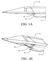
- FIGs. 1A and 1B show representative portions of an exemplary aircraft employing the embodiments of an inlet as disclosed herein.
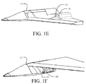
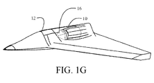
- An inlet 10 is placed under a fuselage 12. While shown in the exemplary embodiment in the drawings as an under fuselage (chin) inlet, alternative embodiments may be employed in fuselage top, over-wing or underwing, under wing root (armpit) and over wing root (shoulder) installations as seen in FIGs. 1C-1G respectively.
- a diffuser 14 extends from the inlet 10 to a jet engine (not shown) which is carried in the fuselage for the exemplary embodiments.
- a compression surface 16 is present on a bottom surface 18 of the fuselage 12 or other aerodynamic structure of the aircraft for cooperative operation with the inlet.
- the inlet 10 configured for operation at the design Mach number is shown in FIGs. 2A and 2B .
- the compression surface 16 may be either a single ramp or an isentropic system for creating the desired compression at the inlet.
- a series of shock waves (represented by exemplary shock waves 20a - 20d) are created by the compression surface 16 yielding the desired compression at the inlet with creation of a normal shock 22 in the inlet aperture.
- the leading edge 24 of the inlet 10 is positioned at the design Mach number to create a nominal area of the inlet aperture in conjunction with the compression surface 16 for desired performance, as will be described in greater detail subsequently.
- the inlet transitions into a diffuser 14 for introduction of flow into the engine.
- the inlet and diffuser are contoured with a curvature to provide flow turning into the engine buried in the aircraft fuselage.
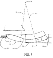
- the inlet 10 is provided with a cowl 26 which incorporates the leading edge 24 as seen in FIG. 3 .
- the cowl 26 is movable to extend and retract the leading edge 24 across a range of positions from a fully retracted position as seen in FIG. 2B to a fully extended position as seen in FIG. 3 . In the fully extended position, the leading edge substantially covers the compression surface.
- the cowl 26 is curved and during extension of the leading edge, the effective area of the inlet aperture is reduced, as will be described in greater detail subsequently.
- the cowl has a radius 28 from a remote axis 30 perpendicular to the direction of airflow into the inlet, as indicated by arrows 31 and transverse to the fixed compression surface.
- a mating scrubbing surface 32 having a radius 29 from the remote axis extended for thickness of the cowl 26 is fixed on the interior of the inlet 10 and engages the cowl for rotation about the remote axis to extend and retract the cowl and leading edge 24 while maintaining a substantially smooth aerodynamic surface for turning of the flow into the diffuser 14. Operation of the aircraft at subsonic speeds is accomplished with the cowl 26 and leading edge 24 in the fully extended position.
- the cowl 26 is retracted, rotating about the remote axis 30.
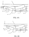
- the leading edge 24 is positioned to expose an initial portion of the fixed compression surface 16 which generates a first desired compression condition with associated positioning of shock wave 20e.
- the cowl 26 is retracted further as seen in FIG. 4B which exposes a greater portion of the fixed compression surface 16 generating a second desired compression condition with positioning of shock waves 20f and 20g.
- FIGs. 4C - 4E Further retraction of the cowl 26 with increasing speeds is shown in FIGs. 4C - 4E with additional exposure of the compression surface 16 at each position.
- the varying compression created by the compression surface is with positioning of the representative shock waves 20h and 20i ( FIG.
- FIGs. 5A-5C An exemplary three dimensional (3D) configuration of the inlet 10 with the cowl 26 is shown in FIGs. 5A-5C with the cowl in the fully extended position, retracted to a mid-position, and fully retracted to the design Mach number position respectively.
- the effective area of the inlet aperture represented in the figures as elements 34a, 34b and 34c is altered by the relative position of the cowl.
- the effective area 34a is significantly reduced over the maximum area 34c over which it is superimposed.
- the effective area 32b is greater than area 34a but remains less than maximum area 34c.
- the effective area 34c is provided as seen in FIG. 6C .
- the area "turn down" which may be achieved by the extension of the cowl is determined by the radius 28 (location of the axis30). A reduced radius provides greater reduction in effective inlet area from fully retracted to fully extended.
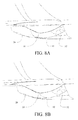
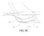
- the exemplary 3D inlet configuration is shown in section in FIG. 7 with detailed views of the cowl 26 and mating scrubbing surfaces 32 shown in FIGs. 8A - 8E in a range of positions from fully extended ( FIG. 8A ) to fully retracted for operation at the design Mach number ( FIG. 8E ).
- the intimate integration of the scrubbing surface 32 and cowl 26 with common radii from the remote axis provide substantially smooth internal surfaces of the inlet for aerodynamic efficiency. While described with respect to the figures at discrete points of extension or retraction, the cowl 26 is smoothly extendible through the entire range from fully retracted to fully extended to allow scheduling of positioning of the cowl to accommodate a range of aircraft speeds up to the design Mach number.
- cowl 26 is shown in the exemplary embodiments as internal to the inlet 10, the cowl may be external to the inlet in alternative embodiments. Further, while the inlet 10 in the present embodiments is shown under a fuselage, the inlet may be positioned on a wing or other structure with the compression surface mounted on a surface of that structure.
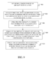
- a method of simultaneous modification of capture area and compression for an aircraft inlet with a fixed compression surface is accomplished for the embodiments disclosed by establishing a leading edge of the inlet on a cowl, step 902.
- the cowl has a radius from an axis and is engaged with a mating scrubbing surface in the inlet with a second radius from the axis to accommodate the thickness of the cowl, step 904.
- the aircraft is operated at a design Mach number with the leading edge and cowl fully retracted, step 906.
- the aircraft is operated at speeds less than the design Mach number with extension of the leading edge over the compression surface, step 908, by rotating the cowl about the axis to simultaneously vary compression and inlet area. Extension of the leading edge may be scheduled from a maximum extended position at subsonic speeds to a fully retracted position at design Mach number, step 910.
Landscapes
- Engineering & Computer Science (AREA)
- Chemical & Material Sciences (AREA)
- Combustion & Propulsion (AREA)
- Aviation & Aerospace Engineering (AREA)
- Mechanical Engineering (AREA)
- Physics & Mathematics (AREA)
- General Engineering & Computer Science (AREA)
- Fluid Mechanics (AREA)
- Geometry (AREA)
- Structures Of Non-Positive Displacement Pumps (AREA)
- Aiming, Guidance, Guns With A Light Source, Armor, Camouflage, And Targets (AREA)
Abstract

Description
- Embodiments of the disclosure relate generally to supersonic inlets for aircraft jet engines and more particularly to an inlet adjustable to simultaneously vary capture area and compression.
- Engine inlets for supersonic aircraft have complex aerodynamic requirements based on Mach number and other flight conditions. Inlet aperture is typically located to provide optimum performance at a nominal design Mach number. To provide necessary flow control a compression surface may be employed in conjunction with the inlet aperture. For simplicity of design, the compression surface is typically fixed. However, inefficiency associated with operation at off-design Mach numbers where mass flow exceeds engine need requires excess air to be spilled or bypassed. Additionally at off-design Mach numbers, the shock waves generated by the compression surface and the resulting compression effects may not be ideal for desired performance.
- It is therefore desirable to provide an inlet which will help improve performance at off-design Mach numbers by adjusting inlet area to minimize or avoid requirements to bypass or spill excess air and simultaneously modifies the shock waves generated by the compression surface.
- Exemplary embodiments provide an engine inlet for efficient operation at both design Mach number and off-design Mach numbers having a fixed compression surface and a leading edge that is variably extendible over the fixed compression surface to simultaneously vary capture area, compression and shock wave position.
- The embodiments provide a method for simultaneous modification of capture area and compression for an aircraft inlet with a fixed compression surface. A leading edge of an inlet is established on a cowl. An aircraft with the inlet is operated at a design Mach number with the leading edge and cowl fully retracted. The aircraft is operated at speeds less than the design Mach number with an extension of the leading edge over a compression surface to simultaneously vary compression and inlet area.
- The features, functions, and advantages that have been discussed can be achieved independently in various embodiments of the present disclosure or may be combined in yet other embodiments, further details of which can be seen with reference to the following description and drawings.
-
FIG. 1A is side view of a portion of an aircraft having an inlet according to an exemplary embodiment as described herein; -
FIG. 1B is a perspective view of a fuselage portion and associated inlet with a fixed compression surface of the embodiment ofFIG. 1A ; -
FIGs. 1C-1G show alternative inlet locations for the embodiment disclosed herein; -
FIG. 2A is side partial section view of the aircraft ofFIG. 1A showing the inlet in section: -
FIG. 2B is a detailed view of the side section of the inlet ofFIG. 2B operating at design Mach number with the fixed ; -
FIG. 3 is a detailed side section view of the inlet with an extended leading edge covering the fixed compression surface; -
FIG. 4A is a detailed side section view of the inlet with the leading edge retracted to a first intermediate position showing exemplary shock wave positions; -
FIG. 4B is a detailed side section view of the inlet with the leading edge retracted to a second intermediate position; -
FIG. 4C is a detailed side section view of the inlet with the leading edge retracted to a third intermediate position; -
FIG. 4D is a detailed side section view of the inlet with the leading edge retracted to a fourth intermediate position; -
FIG. 4E is a detailed side section view of the inlet with the leading edge retracted to a fifth intermediate position; -
FIG. 4F is a detailed side section view of the inlet with the leading edge fully retracted to the design Mach number position showing exemplary shock wave positions; -
FIG. 5A is a pictorial view of the aircraft fuselage and inlet with the leading edge in the fully extended position; -
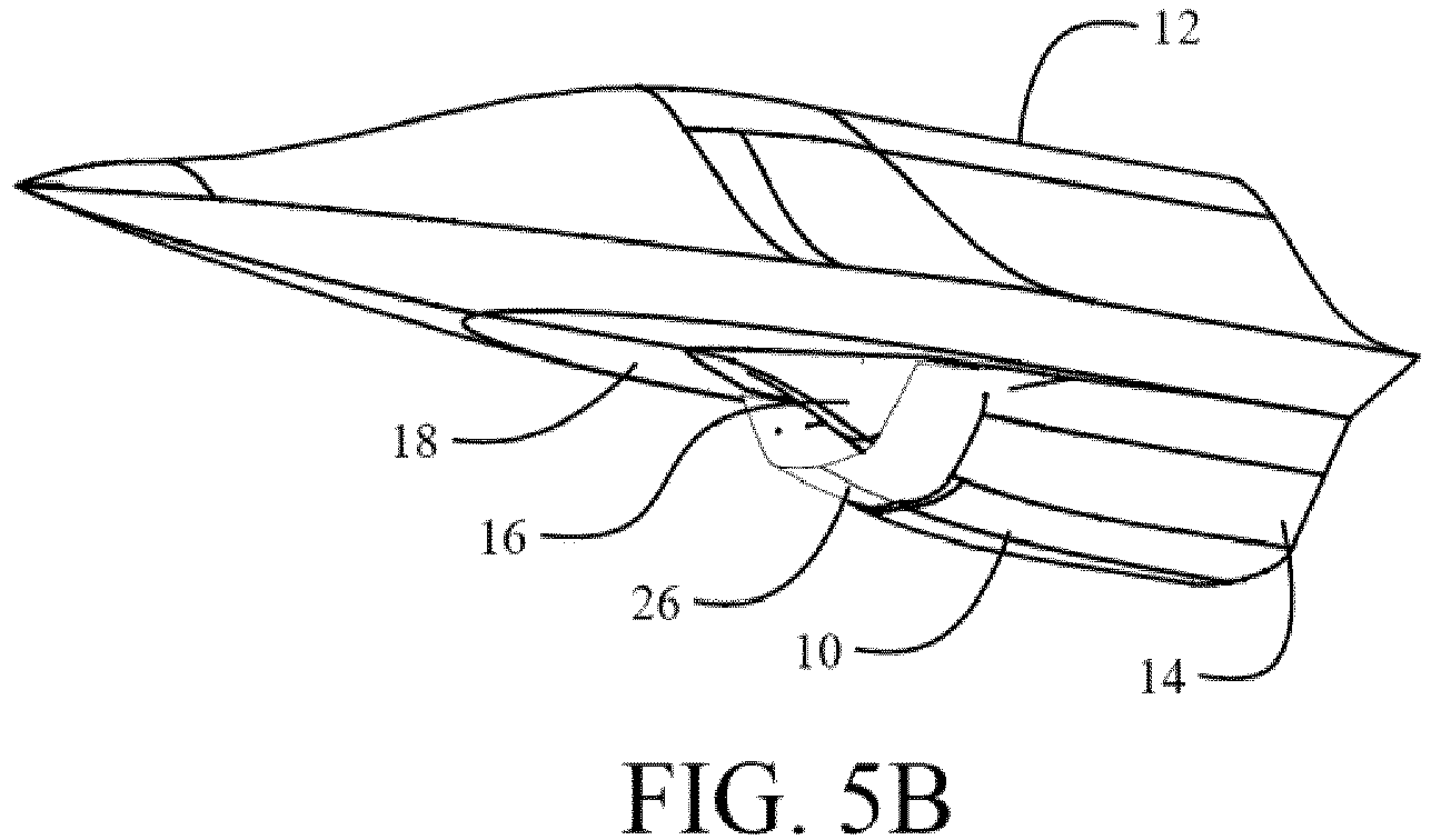
FIG. 5B is a pictorial view of the aircraft fuselage and inlet with the leading edge in an intermediate extended position; -
FIG. 5C is a pictorial view of the aircraft fuselage and inlet with the leading edge in the fully retracted position: -
FIGs. 6A is a pictorial view of the aircraft fuselage and inlet inverted with the leading edge in the fully extended position showing relative inlet area; -
FIGs. 6B is a pictorial view of the aircraft fuselage and inlet inverted with the leading edge in the intermediate extended position showing relative inlet area; -
FIGs. 6C is a pictorial view of the aircraft fuselage and inlet inverted with the leading edge in the fully retracted position showing relative inlet area; -
FIG. 7 is a pictorial section view of the aircraft fuselage and inlet with the leading edge in the fully retracted position showing a structural implementation of the cowl for extending the inlet leading edge; -
FIG. 8A is a pictorial detailed section view of the inlet ofFIG. 7 with the cowl in the fully extended position showing the exposed scrubbing surface receiving the cowl; -
FIG. 8B is a pictorial detailed section view of the inlet ofFIG. 7 with the cowl in a first partially retracted position; -
FIG. 8B is a pictorial detailed section view of the inlet ofFIG. 7 with the cowl in a second partially retracted position; -
FIG. 8C is a pictorial detailed section view of the inlet ofFIG. 7 with the cowl in a third partially retracted position; -
FIG. 8D is a pictorial detailed section view of the inlet ofFIG. 7 with the cowl in a fourth partially retracted position; -
FIG. 8E is a pictorial detailed section view of the inlet ofFIG. 7 with the cowl in a fully retracted position for operation at design Mach number; and, -
FIG. 9 is a flow chart for a method to operate a variable leading edge for matched off-design performance in an inlet having a fixed compression surface. - The system and methods described herein provide embodiments for an inlet having a leading edge variably extendible over a fixed compression surface to simultaneously vary capture area and compression. The inlet leading edge may be configured on a cowl to pivot about a remote axis perpendicular to the direction of airflow and transverse to the compression surface. The capture area is adjusted by extension and retraction of the cowl and leading edge to match mass flow with engine need and/or align with off-design shock waves from the compression surface. Thereby minimizing or obviating excess airflow to be spilled or caused to bypass the inlet. The inlet is also configured such that as the leading edge is retracted with increasing speed and increasing amount of compression surface is exposed thereby increasing the capture area. The position of the inlet leading edge relative to the fixed compression surface also causes the compression to vary and repositions the shock waves created by the compression surface. Pivoting the inlet cowl about a remote axis with mating scrubbing surfaces in the inlet flow path defined by the radius to the axis and consistent with desired flow turning into a diffuser for the aircraft engine provides for a simple mechanism to simultaneously vary capture area, compression and shock wave position to enhance efficiency.
- Referring to the drawings,
FIGs. 1A and 1B show representative portions of an exemplary aircraft employing the embodiments of an inlet as disclosed herein. Aninlet 10 is placed under afuselage 12. While shown in the exemplary embodiment in the drawings as an under fuselage (chin) inlet, alternative embodiments may be employed in fuselage top, over-wing or underwing, under wing root (armpit) and over wing root (shoulder) installations as seen inFIGs. 1C-1G respectively. Adiffuser 14 extends from theinlet 10 to a jet engine (not shown) which is carried in the fuselage for the exemplary embodiments. Acompression surface 16 is present on abottom surface 18 of thefuselage 12 or other aerodynamic structure of the aircraft for cooperative operation with the inlet. - The
inlet 10 configured for operation at the design Mach number is shown inFIGs. 2A and 2B . Thecompression surface 16 may be either a single ramp or an isentropic system for creating the desired compression at the inlet. As seen inFIG. 2B , a series of shock waves (represented byexemplary shock waves 20a - 20d) are created by thecompression surface 16 yielding the desired compression at the inlet with creation of anormal shock 22 in the inlet aperture. The leadingedge 24 of theinlet 10 is positioned at the design Mach number to create a nominal area of the inlet aperture in conjunction with thecompression surface 16 for desired performance, as will be described in greater detail subsequently. As seen in the section view, the inlet transitions into adiffuser 14 for introduction of flow into the engine. The inlet and diffuser are contoured with a curvature to provide flow turning into the engine buried in the aircraft fuselage. - For operation at speeds less than the design Mach number, the
inlet 10 is provided with acowl 26 which incorporates the leadingedge 24 as seen inFIG. 3 . Thecowl 26 is movable to extend and retract theleading edge 24 across a range of positions from a fully retracted position as seen inFIG. 2B to a fully extended position as seen inFIG. 3 . In the fully extended position, the leading edge substantially covers the compression surface. Thecowl 26 is curved and during extension of the leading edge, the effective area of the inlet aperture is reduced, as will be described in greater detail subsequently. For the embodiment shown, the cowl has aradius 28 from aremote axis 30 perpendicular to the direction of airflow into the inlet, as indicated byarrows 31 and transverse to the fixed compression surface. Amating scrubbing surface 32 having aradius 29 from the remote axis extended for thickness of thecowl 26 is fixed on the interior of theinlet 10 and engages the cowl for rotation about the remote axis to extend and retract the cowl and leadingedge 24 while maintaining a substantially smooth aerodynamic surface for turning of the flow into thediffuser 14. Operation of the aircraft at subsonic speeds is accomplished with thecowl 26 and leadingedge 24 in the fully extended position. - As speed of the aircraft is increased, the
cowl 26 is retracted, rotating about theremote axis 30. In a first representative position seen inFIG. 4A , the leadingedge 24 is positioned to expose an initial portion of the fixedcompression surface 16 which generates a first desired compression condition with associated positioning ofshock wave 20e. With further increase in speed, thecowl 26 is retracted further as seen inFIG. 4B which exposes a greater portion of the fixedcompression surface 16 generating a second desired compression condition with positioning ofshock waves 20f and 20g. Further retraction of thecowl 26 with increasing speeds is shown inFIGs. 4C - 4E with additional exposure of thecompression surface 16 at each position. The varying compression created by the compression surface is with positioning of therepresentative shock waves 20h and 20i (FIG. 4C ), 20j, 20k and 20l (FIG. 4D ) and 20m, 20n and 20o (FIG. 4E ). At the fully retracted condition when the aircraft reaches the design Mach number shown inFIG. 4F , the cowl exposes the maximum extent of thecompression surface 16 with commensurate compression defined byshock waves 20a - 20d as previously described with respect toFIG. 2B . - An exemplary three dimensional (3D) configuration of the
inlet 10 with thecowl 26 is shown inFIGs. 5A-5C with the cowl in the fully extended position, retracted to a mid-position, and fully retracted to the design Mach number position respectively. As seen in correspondingFIGs. 6A-6C with the 3D configuration inverted for clarity, the effective area of the inlet aperture represented in the figures aselements FIG. 6A with thecowl 26 in the fully extended position theeffective area 34a is significantly reduced over themaximum area 34c over which it is superimposed. In the mid-position ofFIG. 6B , the effective area 32b is greater thanarea 34a but remains less thanmaximum area 34c. With thecowl 26 fully retracted, theeffective area 34c is provided as seen inFIG. 6C .Within the limits of effective flow turning in the inlet and diffuser, the area "turn down" which may be achieved by the extension of the cowl is determined by the radius 28 (location of the axis30). A reduced radius provides greater reduction in effective inlet area from fully retracted to fully extended. - The exemplary 3D inlet configuration is shown in section in
FIG. 7 with detailed views of thecowl 26 and mating scrubbing surfaces 32 shown inFIGs. 8A - 8E in a range of positions from fully extended (FIG. 8A ) to fully retracted for operation at the design Mach number (FIG. 8E ). The intimate integration of the scrubbingsurface 32 andcowl 26 with common radii from the remote axis provide substantially smooth internal surfaces of the inlet for aerodynamic efficiency. While described with respect to the figures at discrete points of extension or retraction, thecowl 26 is smoothly extendible through the entire range from fully retracted to fully extended to allow scheduling of positioning of the cowl to accommodate a range of aircraft speeds up to the design Mach number. Additionally, while thecowl 26 is shown in the exemplary embodiments as internal to theinlet 10, the cowl may be external to the inlet in alternative embodiments. Further, while theinlet 10 in the present embodiments is shown under a fuselage, the inlet may be positioned on a wing or other structure with the compression surface mounted on a surface of that structure. - A method of simultaneous modification of capture area and compression for an aircraft inlet with a fixed compression surface is accomplished for the embodiments disclosed by establishing a leading edge of the inlet on a cowl,
step 902. The cowl has a radius from an axis and is engaged with a mating scrubbing surface in the inlet with a second radius from the axis to accommodate the thickness of the cowl,step 904. The aircraft is operated at a design Mach number with the leading edge and cowl fully retracted,step 906. The aircraft is operated at speeds less than the design Mach number with extension of the leading edge over the compression surface,step 908, by rotating the cowl about the axis to simultaneously vary compression and inlet area. Extension of the leading edge may be scheduled from a maximum extended position at subsonic speeds to a fully retracted position at design Mach number,step 910. - Illustrative, non-exclusive examples of inventive subject matter according to the present disclosure are described in clauses A1-C21, below:
- A1. An
engine inlet 10 for efficient operation at off-design Mach number comprising:- a fixed
compression surface 16; and, - a
leading edge 24 that is variably extendible over the fixed compression surface to simultaneously vary capture area, compression and shock wave position.
- a fixed
- A2. The
engine inlet 10 for efficient operation at off-design Mach number as defined in clause A1 further comprising:- a
cowl 26 incorporating the leadingedge 24, said cowl movable to extend and retract the leading edge across a range of positions from a fully retracted position to a fully extended position.
- a
- A3. The
engine inlet 10 for efficient operation at off-design Mach number as defined in clause A2 wherein thecowl 26 has aradius 28 from aremote axis 30 perpendicular to adirection 31 of airflow and transverse to the fixedcompression surface 16. - A4. The
engine inlet 10 for efficient operation at off-design Mach number as defined in clause A3 further comprising amating scrubbing surface 32 having aradius 29 from theremote axis 30 extended for thickness of thecowl 26 , said scrubbing surface engaging the cowl for rotation about the remote axis to extend and retract the cowl. - A5. The
engine inlet 10 for efficient operation at off-design Mach number as defined in any of clauses A1-A4 wherein the leadingedge 24 is fully retracted at a design Mach number. - A6. The
engine inlet 10 for efficient operation at off-design Mach number as defined in any of clauses A1-A5 wherein the leadingedge 24 is fully extended at subsonic operation. - A7. The engine inlet in any of clauses A1-A6, wherein the compression surface is disposed on a surface selected from a fuselage bottom, fuselage top, fuselage side, wing top and wing bottom.
- B8. An aircraft having efficient operation at off-design Mach number comprising:
- an aerodynamic structure;
- an
inlet 10 having- a fixed
compression surface 16 mounted on a surface of the aerodynamic structure; and, - a
leading edge 24 that is variably extendible over the fixed compression surface to simultaneously vary capture area, compression and shock wave position.
- a fixed
- B9. The aircraft having efficient operation at off-design Mach number as defined in clause B8 further comprising:
- a
cowl 26 incorporating the leadingedge 24, said cowl movable to extend and retract the leading edge across a range of positions from a fully retracted position to a fully extended position.
- a
- B10. The aircraft having efficient operation at off-design Mach number as defined in clause B9 wherein the
cowl 26 has aradius 28 from aremote axis 30 perpendicular to a direction of airflow and transverse to the fixed compression surface. - B11. The aircraft having efficient operation at off-design Mach number as defined in clause B10 further comprising a
mating scrubbing surface 32 having aradius 29 from theremote axis 30 extended for thickness of the cowl, said scrubbing surface engaging the cowl for rotation about the remote axis to extend and retract the cowl. - B12. The aircraft having efficient operation at off-design Mach number as defined in any of clauses B8-B11 wherein the leading
edge 24 is fully retracted at a design Mach number. - B13. The aircraft having efficient operation at off-design Mach number as defined in any of clauses B8-B12 wherein the leading
edge 24 is fully extended at subsonic operation. - B14. The aircraft having efficient operation at off-design Mach number as defined in any of clauses B8-B13 wherein the aerodynamic structure is a
fuselage 12 and the surface is selected from a bottom surface and a top surface of the fuselage. - B15. The aircraft having efficient operation at off-design Mach number as defined in any of clauses B8-B13 wherein the aerodynamic structure is selected from a wing and the surface is selected from a bottom surface of the wing, a top surface of the wing.
- B16. The aircraft having efficient operation at off-design Mach number as defined in any of clauses B8-B13 wherein the aerodynamic structure is selected from a wing and
fuselage 12 and the surface is selected from a top surface of the wing and a side surface of the fuselage. - C17. A method for simultaneous modification of capture area and compression for an aircraft inlet with a fixed compression surface comprising
- establishing 902 a
leading edge 24 of aninlet 10 on acowl 26 movable relative to the fixed compression surface; - operating 908 the aircraft with the inlet at speeds less than a design Mach number with the leading edge and cowl extended; and
- operating 906 the aircraft at the design Mach number with the leading edge fully retracted.
- establishing 902 a
- C18. The method as defined in clause C17 further comprising:
- engaging 904 the
cowl 26 with amating scrubbing surface 32 in theinlet 10, the cowl having aradius 28 from anaxis 30 and the scrubbing surface having asecond radius 29 from the axis to accommodate a thickness of the cowl.
- engaging 904 the
- C19. The method as defined in clause C18 wherein the step of extending the leading
edge 24 comprises rotating thecowl 26 about theaxis 28. - C20. The method as defined in any of clauses C17-C19 further comprising
scheduling 910 extension of the leadingedge 24 from a maximum extended position at subsonic speeds to a fully retracted position at design Mach number. - C21. The method as defined in any of clauses C17-C20 wherein the
compression surface 16 is disposed on a surface selected from a fuselage bottom, a fuselage top, a wing top, a wing bottom and a fuselage side. - Having now described various embodiments of the disclosure in detail as required by the patent statutes, those skilled in the art will recognize modifications and substitutions to the specific embodiments disclosed herein. Such modifications are within the scope and intent of the present disclosure as defined in the following claims.
Claims (12)
- An engine inlet (10) for efficient operation at off-design Mach number comprising:a fixed compression surface (16); and,a leading edge (24) that is variably extendible over the fixed compression surface to simultaneously vary capture area, compression and shock wave position.
- The engine inlet (10) for efficient operation at off-design Mach number as defined in claim 1 further comprising:a cowl (26) incorporating the leading edge (24), said cowl movable to extend and retract the leading edge across a range of positions from a fully retracted position to a fully extended position.
- The engine inlet (10) for efficient operation at off-design Mach number as defined in claim 2 wherein the cowl (26) has a radius (28) from a remote axis (30) perpendicular to a direction (31) of airflow and transverse to the fixed compression surface (16).
- The engine inlet (10) for efficient operation at off-design Mach number as defined in claim 3 further comprising a mating scrubbing surface (32) having a radius (29) from the remote axis (30) extended for thickness of the cowl (26), said scrubbing surface engaging the cowl for rotation about the remote axis to extend and retract the cowl.
- The engine inlet (10) for efficient operation at off-design Mach number as defined in any of claims 1-4 wherein the leading edge (24) is fully retracted at a design Mach number.
- The engine inlet (10) for efficient operation at off-design Mach number as defined in any of claims 1-5 wherein the leading edge (24) is fully extended at subsonic operation.
- The engine inlet in any of claims 1-6, wherein the compression surface is disposed on a surface selected from a fuselage bottom, fuselage top, fuselage side, wing top and wing bottom.
- A method for simultaneous modification of capture area and compression for an aircraft inlet with a fixed compression surface comprisingestablishing (902) a leading edge (24) of an inlet (10) on a cowl (26) movable relative to the fixed compression surface;operating (908) the aircraft with the inlet at speeds less than a design Mach number with the leading edge and cowl extended; andoperating (906) the aircraft at the design Mach number with the leading edge fully retracted.
- The method as defined in claim 8 further comprising:engaging (904) the cowl (26) with a mating scrubbing surface (32) in the inlet (10), the cowl having a radius (28) from an axis (30) and the scrubbing surface having a second radius (29) from the axis to accommodate a thickness of the cowl.
- The method as defined in claim 9 wherein the step of extending the leading edge (24) comprises rotating the cowl (26) about the axis (28).
- The method as defined in any of claims 8-10 further comprising scheduling (910) extension of the leading edge (24) from a maximum extended position at subsonic speeds to a fully retracted position at design Mach number.
- The method as defined in any of claims 8-11 wherein the compression surface (16) is disposed on a surface selected from a fuselage bottom, a fuselage top, a wing top, a wing bottom and a fuselage side.
Applications Claiming Priority (1)
| Application Number | Priority Date | Filing Date | Title |
|---|---|---|---|
| US14/674,170 US9908633B2 (en) | 2015-03-31 | 2015-03-31 | Variable-capture supersonic inlet |
Publications (2)
| Publication Number | Publication Date |
|---|---|
| EP3075663A1 true EP3075663A1 (en) | 2016-10-05 |
| EP3075663B1 EP3075663B1 (en) | 2021-03-10 |
Family
ID=55168167
Family Applications (1)
| Application Number | Title | Priority Date | Filing Date |
|---|---|---|---|
| EP16151379.1A Active EP3075663B1 (en) | 2015-03-31 | 2016-01-14 | Variable-capture supersonic inlet |
Country Status (3)
| Country | Link |
|---|---|
| US (1) | US9908633B2 (en) |
| EP (1) | EP3075663B1 (en) |
| CN (1) | CN106121824B (en) |
Cited By (2)
| Publication number | Priority date | Publication date | Assignee | Title |
|---|---|---|---|---|
| US20180339784A1 (en) * | 2017-05-24 | 2018-11-29 | Sikorsky Aircraft Corporation | Variable geometry engine inlet for high speed aircraft |
| US11261785B2 (en) | 2017-06-06 | 2022-03-01 | Raytheon Company | Flight vehicle air breathing engine with isolator having bulged section |
Families Citing this family (11)
| Publication number | Priority date | Publication date | Assignee | Title |
|---|---|---|---|---|
| EP3412563B1 (en) * | 2017-06-08 | 2022-11-23 | Airbus Defence and Space GmbH | Variable and adaptable diverterless bump inlet |
| US11441482B2 (en) | 2019-06-04 | 2022-09-13 | Rohr, Inc. | Single track translating inlet |
| US11390393B2 (en) | 2019-06-04 | 2022-07-19 | Rohr, Inc. | Nacelle with a translatable inlet for an aircraft propulsion system |
| US11725581B2 (en) | 2021-06-25 | 2023-08-15 | Rohr, Inc. | Aircraft propulsion system with variable area inlet |
| US11560841B2 (en) | 2021-06-25 | 2023-01-24 | Rohr, Inc. | Aircraft propulsion system with variable area inlet |
| US11767124B2 (en) | 2021-09-10 | 2023-09-26 | Rohr, Inc. | Aircraft propulsion system with variable area inlet |
| US11840985B2 (en) | 2021-09-10 | 2023-12-12 | Rohr, Inc. | Aircraft propulsion system with variable area inlet |
| CN114852351A (en) * | 2022-06-02 | 2022-08-05 | 上海甘石星经智能科技有限公司 | Low-resistance and high-efficiency subsonic inlet channel |
| US20240229713A1 (en) * | 2022-09-15 | 2024-07-11 | Rohr, Inc. | Aircraft propulsion system with variable area inlet |
| DE102022129097B3 (en) | 2022-11-03 | 2024-03-14 | Airbus Defence and Space GmbH | Aircraft structure with an improved inlet opening for engine air |
| CN118793516B (en) * | 2024-06-24 | 2025-11-28 | 南京航空航天大学 | Axisymmetric double-S-bend ramjet engine air inlet channel and design method thereof |
Citations (4)
| Publication number | Priority date | Publication date | Assignee | Title |
|---|---|---|---|---|
| GB761235A (en) * | 1953-02-24 | 1956-11-14 | Rolls Royce | Improvements in or relating to air intakes for jet-propulsion power plants |
| GB926345A (en) * | 1961-05-30 | 1963-05-15 | Svenska Flygmotor Aktiebolaget | Improvements in and relating to air intakes for jet propulsion engines |
| US3242671A (en) * | 1964-04-08 | 1966-03-29 | Boeing Co | Fixed spike inlet with variable throat and capture area |
| US3974648A (en) * | 1968-08-19 | 1976-08-17 | United Technologies Corporation | Variable geometry ramjet engine |
Family Cites Families (7)
| Publication number | Priority date | Publication date | Assignee | Title |
|---|---|---|---|---|
| US3067573A (en) * | 1958-02-27 | 1962-12-11 | James F Connors | Telescoping-spike supersonic inlet for aircraft engines |
| US4477039A (en) * | 1982-06-30 | 1984-10-16 | Mcdonnell Douglas Corporation | Vented cowl variable geometry inlet for aircraft |
| FR2710607B1 (en) * | 1993-10-01 | 1995-12-01 | Onera (Off Nat Aerospatiale) | Two-dimensional supersonic and hypersonic air inlet, with three movable ramps, for the combustion air of an aircraft engine. |
| US7837142B2 (en) * | 2006-10-12 | 2010-11-23 | Aerion Corporation | Supersonic aircraft jet engine |
| CN101798961B (en) * | 2010-03-29 | 2012-08-22 | 南京航空航天大学 | Two-stage beveled supersonic speed air inlet lip |
| GB201117079D0 (en) * | 2011-10-05 | 2011-11-16 | Rolls Royce Plc | A propulsive unit for an aircraft |
| CN103939217B (en) * | 2014-04-18 | 2016-03-02 | 南京航空航天大学 | Rectangular cross-section hypersonic change geometry intake duct and design method and working method |
-
2015
- 2015-03-31 US US14/674,170 patent/US9908633B2/en active Active
-
2016
- 2016-01-14 EP EP16151379.1A patent/EP3075663B1/en active Active
- 2016-03-17 CN CN201610157395.5A patent/CN106121824B/en active Active
Patent Citations (4)
| Publication number | Priority date | Publication date | Assignee | Title |
|---|---|---|---|---|
| GB761235A (en) * | 1953-02-24 | 1956-11-14 | Rolls Royce | Improvements in or relating to air intakes for jet-propulsion power plants |
| GB926345A (en) * | 1961-05-30 | 1963-05-15 | Svenska Flygmotor Aktiebolaget | Improvements in and relating to air intakes for jet propulsion engines |
| US3242671A (en) * | 1964-04-08 | 1966-03-29 | Boeing Co | Fixed spike inlet with variable throat and capture area |
| US3974648A (en) * | 1968-08-19 | 1976-08-17 | United Technologies Corporation | Variable geometry ramjet engine |
Cited By (4)
| Publication number | Priority date | Publication date | Assignee | Title |
|---|---|---|---|---|
| US20180339784A1 (en) * | 2017-05-24 | 2018-11-29 | Sikorsky Aircraft Corporation | Variable geometry engine inlet for high speed aircraft |
| US10723474B2 (en) * | 2017-05-24 | 2020-07-28 | Sikorsky Aircraft Corporation | Variable geometry engine inlet for high speed aircraft |
| US11261785B2 (en) | 2017-06-06 | 2022-03-01 | Raytheon Company | Flight vehicle air breathing engine with isolator having bulged section |
| EP3635233B1 (en) * | 2017-06-06 | 2022-03-30 | Raytheon Company | Flight vehicle air breathing engine with isolator having bulged section and method of operating such an engine |
Also Published As
| Publication number | Publication date |
|---|---|
| CN106121824B (en) | 2019-11-29 |
| US9908633B2 (en) | 2018-03-06 |
| US20160288917A1 (en) | 2016-10-06 |
| CN106121824A (en) | 2016-11-16 |
| EP3075663B1 (en) | 2021-03-10 |
Similar Documents
| Publication | Publication Date | Title |
|---|---|---|
| EP3075663A1 (en) | Variable-capture supersonic inlet | |
| EP3069999B1 (en) | Supersonic caret inlet system leading edge slat for improved inlet performance at off-design flight conditions | |
| US9885291B2 (en) | Turbomachine comprising a plurality of fixed radial blades mounted upstream of the fan | |
| EP1206384B1 (en) | Supersonic external-compression diffuser and method for designing same | |
| EP3048049A1 (en) | Supersonic caret inlet system | |
| US6276632B1 (en) | Axi-symmetric mixed compression inlet with variable geometry centerbody | |
| US10436112B2 (en) | Translating turning vanes for a nacelle inlet | |
| US10309343B2 (en) | Split sleeve hidden door thrust reverser | |
| US6910327B2 (en) | Apparatus and methods for varying inlet lip geometry of a jet engine inlet | |
| EP3421373A1 (en) | Rotating devices for mitigation of adverse flow conditions in an ultra-short nacelle inlet | |
| US10794280B2 (en) | Air intake for gas turbine engine | |
| EP3480448A1 (en) | Fan cowl with a serrated trailing edge providing attached flow in reverse thrust mode | |
| US9879561B2 (en) | Turbomachine comprising a plurality of fixed radial blades mounted upstream of the fan | |
| US8371324B1 (en) | Collapsible supersonic inlet centerbody | |
| GB2549912A (en) | Device for the individual adjustment of a plurality of variable-pitch radial stator vanes in a turbomachine | |
| US20190136695A1 (en) | Turbine wheel for a turbine | |
| EP4406849A1 (en) | Variable geometry inlet for turbopropeller inlet pressure recovery optimization | |
| EP2921684A1 (en) | Integrated primary nozzle | |
| US12281613B2 (en) | Turbofan engine with at least one guide vane including a variable-geometry zone | |
| BRPI0619996A2 (en) | isentropic compression inlet for a supersonic aircraft |
Legal Events
| Date | Code | Title | Description |
|---|---|---|---|
| PUAI | Public reference made under article 153(3) epc to a published international application that has entered the european phase |
Free format text: ORIGINAL CODE: 0009012 |
|
| 17P | Request for examination filed |
Effective date: 20160114 |
|
| AK | Designated contracting states |
Kind code of ref document: A1 Designated state(s): AL AT BE BG CH CY CZ DE DK EE ES FI FR GB GR HR HU IE IS IT LI LT LU LV MC MK MT NL NO PL PT RO RS SE SI SK SM TR |
|
| AX | Request for extension of the european patent |
Extension state: BA ME |
|
| RBV | Designated contracting states (corrected) |
Designated state(s): AL AT BE BG CH CY CZ DE DK EE ES FI FR GB GR HR HU IE IS IT LI LT LU LV MC MK MT NL NO PL PT RO RS SE SI SK SM TR |
|
| STAA | Information on the status of an ep patent application or granted ep patent |
Free format text: STATUS: EXAMINATION IS IN PROGRESS |
|
| 17Q | First examination report despatched |
Effective date: 20181010 |
|
| GRAP | Despatch of communication of intention to grant a patent |
Free format text: ORIGINAL CODE: EPIDOSNIGR1 |
|
| STAA | Information on the status of an ep patent application or granted ep patent |
Free format text: STATUS: GRANT OF PATENT IS INTENDED |
|
| INTG | Intention to grant announced |
Effective date: 20200402 |
|
| GRAS | Grant fee paid |
Free format text: ORIGINAL CODE: EPIDOSNIGR3 |
|
| GRAJ | Information related to disapproval of communication of intention to grant by the applicant or resumption of examination proceedings by the epo deleted |
Free format text: ORIGINAL CODE: EPIDOSDIGR1 |
|
| GRAL | Information related to payment of fee for publishing/printing deleted |
Free format text: ORIGINAL CODE: EPIDOSDIGR3 |
|
| GRAJ | Information related to disapproval of communication of intention to grant by the applicant or resumption of examination proceedings by the epo deleted |
Free format text: ORIGINAL CODE: EPIDOSDIGR1 |
|
| GRAL | Information related to payment of fee for publishing/printing deleted |
Free format text: ORIGINAL CODE: EPIDOSDIGR3 |
|
| STAA | Information on the status of an ep patent application or granted ep patent |
Free format text: STATUS: EXAMINATION IS IN PROGRESS |
|
| INTG | Intention to grant announced |
Effective date: 20200402 |
|
| INTC | Intention to grant announced (deleted) | ||
| GRAP | Despatch of communication of intention to grant a patent |
Free format text: ORIGINAL CODE: EPIDOSNIGR1 |
|
| STAA | Information on the status of an ep patent application or granted ep patent |
Free format text: STATUS: GRANT OF PATENT IS INTENDED |
|
| INTG | Intention to grant announced |
Effective date: 20201007 |
|
| GRAA | (expected) grant |
Free format text: ORIGINAL CODE: 0009210 |
|
| STAA | Information on the status of an ep patent application or granted ep patent |
Free format text: STATUS: THE PATENT HAS BEEN GRANTED |
|
| AK | Designated contracting states |
Kind code of ref document: B1 Designated state(s): AL AT BE BG CH CY CZ DE DK EE ES FI FR GB GR HR HU IE IS IT LI LT LU LV MC MK MT NL NO PL PT RO RS SE SI SK SM TR |
|
| REG | Reference to a national code |
Ref country code: GB Ref legal event code: FG4D |
|
| REG | Reference to a national code |
Ref country code: AT Ref legal event code: REF Ref document number: 1369579 Country of ref document: AT Kind code of ref document: T Effective date: 20210315 Ref country code: CH Ref legal event code: EP |
|
| REG | Reference to a national code |
Ref country code: IE Ref legal event code: FG4D |
|
| REG | Reference to a national code |
Ref country code: DE Ref legal event code: R096 Ref document number: 602016053878 Country of ref document: DE |
|
| REG | Reference to a national code |
Ref country code: LT Ref legal event code: MG9D |
|
| PG25 | Lapsed in a contracting state [announced via postgrant information from national office to epo] |
Ref country code: LT Free format text: LAPSE BECAUSE OF FAILURE TO SUBMIT A TRANSLATION OF THE DESCRIPTION OR TO PAY THE FEE WITHIN THE PRESCRIBED TIME-LIMIT Effective date: 20210310 Ref country code: GR Free format text: LAPSE BECAUSE OF FAILURE TO SUBMIT A TRANSLATION OF THE DESCRIPTION OR TO PAY THE FEE WITHIN THE PRESCRIBED TIME-LIMIT Effective date: 20210611 Ref country code: HR Free format text: LAPSE BECAUSE OF FAILURE TO SUBMIT A TRANSLATION OF THE DESCRIPTION OR TO PAY THE FEE WITHIN THE PRESCRIBED TIME-LIMIT Effective date: 20210310 Ref country code: FI Free format text: LAPSE BECAUSE OF FAILURE TO SUBMIT A TRANSLATION OF THE DESCRIPTION OR TO PAY THE FEE WITHIN THE PRESCRIBED TIME-LIMIT Effective date: 20210310 Ref country code: BG Free format text: LAPSE BECAUSE OF FAILURE TO SUBMIT A TRANSLATION OF THE DESCRIPTION OR TO PAY THE FEE WITHIN THE PRESCRIBED TIME-LIMIT Effective date: 20210610 Ref country code: NO Free format text: LAPSE BECAUSE OF FAILURE TO SUBMIT A TRANSLATION OF THE DESCRIPTION OR TO PAY THE FEE WITHIN THE PRESCRIBED TIME-LIMIT Effective date: 20210610 |
|
| REG | Reference to a national code |
Ref country code: AT Ref legal event code: MK05 Ref document number: 1369579 Country of ref document: AT Kind code of ref document: T Effective date: 20210310 |
|
| REG | Reference to a national code |
Ref country code: NL Ref legal event code: MP Effective date: 20210310 |
|
| PG25 | Lapsed in a contracting state [announced via postgrant information from national office to epo] |
Ref country code: RS Free format text: LAPSE BECAUSE OF FAILURE TO SUBMIT A TRANSLATION OF THE DESCRIPTION OR TO PAY THE FEE WITHIN THE PRESCRIBED TIME-LIMIT Effective date: 20210310 Ref country code: LV Free format text: LAPSE BECAUSE OF FAILURE TO SUBMIT A TRANSLATION OF THE DESCRIPTION OR TO PAY THE FEE WITHIN THE PRESCRIBED TIME-LIMIT Effective date: 20210310 Ref country code: SE Free format text: LAPSE BECAUSE OF FAILURE TO SUBMIT A TRANSLATION OF THE DESCRIPTION OR TO PAY THE FEE WITHIN THE PRESCRIBED TIME-LIMIT Effective date: 20210310 |
|
| PG25 | Lapsed in a contracting state [announced via postgrant information from national office to epo] |
Ref country code: NL Free format text: LAPSE BECAUSE OF FAILURE TO SUBMIT A TRANSLATION OF THE DESCRIPTION OR TO PAY THE FEE WITHIN THE PRESCRIBED TIME-LIMIT Effective date: 20210310 |
|
| PG25 | Lapsed in a contracting state [announced via postgrant information from national office to epo] |
Ref country code: EE Free format text: LAPSE BECAUSE OF FAILURE TO SUBMIT A TRANSLATION OF THE DESCRIPTION OR TO PAY THE FEE WITHIN THE PRESCRIBED TIME-LIMIT Effective date: 20210310 Ref country code: CZ Free format text: LAPSE BECAUSE OF FAILURE TO SUBMIT A TRANSLATION OF THE DESCRIPTION OR TO PAY THE FEE WITHIN THE PRESCRIBED TIME-LIMIT Effective date: 20210310 Ref country code: AT Free format text: LAPSE BECAUSE OF FAILURE TO SUBMIT A TRANSLATION OF THE DESCRIPTION OR TO PAY THE FEE WITHIN THE PRESCRIBED TIME-LIMIT Effective date: 20210310 Ref country code: SM Free format text: LAPSE BECAUSE OF FAILURE TO SUBMIT A TRANSLATION OF THE DESCRIPTION OR TO PAY THE FEE WITHIN THE PRESCRIBED TIME-LIMIT Effective date: 20210310 |
|
| PG25 | Lapsed in a contracting state [announced via postgrant information from national office to epo] |
Ref country code: IS Free format text: LAPSE BECAUSE OF FAILURE TO SUBMIT A TRANSLATION OF THE DESCRIPTION OR TO PAY THE FEE WITHIN THE PRESCRIBED TIME-LIMIT Effective date: 20210710 Ref country code: RO Free format text: LAPSE BECAUSE OF FAILURE TO SUBMIT A TRANSLATION OF THE DESCRIPTION OR TO PAY THE FEE WITHIN THE PRESCRIBED TIME-LIMIT Effective date: 20210310 Ref country code: SK Free format text: LAPSE BECAUSE OF FAILURE TO SUBMIT A TRANSLATION OF THE DESCRIPTION OR TO PAY THE FEE WITHIN THE PRESCRIBED TIME-LIMIT Effective date: 20210310 Ref country code: PT Free format text: LAPSE BECAUSE OF FAILURE TO SUBMIT A TRANSLATION OF THE DESCRIPTION OR TO PAY THE FEE WITHIN THE PRESCRIBED TIME-LIMIT Effective date: 20210712 Ref country code: PL Free format text: LAPSE BECAUSE OF FAILURE TO SUBMIT A TRANSLATION OF THE DESCRIPTION OR TO PAY THE FEE WITHIN THE PRESCRIBED TIME-LIMIT Effective date: 20210310 Ref country code: ES Free format text: LAPSE BECAUSE OF FAILURE TO SUBMIT A TRANSLATION OF THE DESCRIPTION OR TO PAY THE FEE WITHIN THE PRESCRIBED TIME-LIMIT Effective date: 20210310 |
|
| REG | Reference to a national code |
Ref country code: DE Ref legal event code: R097 Ref document number: 602016053878 Country of ref document: DE |
|
| PLBE | No opposition filed within time limit |
Free format text: ORIGINAL CODE: 0009261 |
|
| STAA | Information on the status of an ep patent application or granted ep patent |
Free format text: STATUS: NO OPPOSITION FILED WITHIN TIME LIMIT |
|
| PG25 | Lapsed in a contracting state [announced via postgrant information from national office to epo] |
Ref country code: DK Free format text: LAPSE BECAUSE OF FAILURE TO SUBMIT A TRANSLATION OF THE DESCRIPTION OR TO PAY THE FEE WITHIN THE PRESCRIBED TIME-LIMIT Effective date: 20210310 Ref country code: AL Free format text: LAPSE BECAUSE OF FAILURE TO SUBMIT A TRANSLATION OF THE DESCRIPTION OR TO PAY THE FEE WITHIN THE PRESCRIBED TIME-LIMIT Effective date: 20210310 |
|
| 26N | No opposition filed |
Effective date: 20211213 |
|
| PG25 | Lapsed in a contracting state [announced via postgrant information from national office to epo] |
Ref country code: SI Free format text: LAPSE BECAUSE OF FAILURE TO SUBMIT A TRANSLATION OF THE DESCRIPTION OR TO PAY THE FEE WITHIN THE PRESCRIBED TIME-LIMIT Effective date: 20210310 |
|
| PG25 | Lapsed in a contracting state [announced via postgrant information from national office to epo] |
Ref country code: IT Free format text: LAPSE BECAUSE OF FAILURE TO SUBMIT A TRANSLATION OF THE DESCRIPTION OR TO PAY THE FEE WITHIN THE PRESCRIBED TIME-LIMIT Effective date: 20210310 |
|
| PG25 | Lapsed in a contracting state [announced via postgrant information from national office to epo] |
Ref country code: IS Free format text: LAPSE BECAUSE OF FAILURE TO SUBMIT A TRANSLATION OF THE DESCRIPTION OR TO PAY THE FEE WITHIN THE PRESCRIBED TIME-LIMIT Effective date: 20210710 |
|
| PG25 | Lapsed in a contracting state [announced via postgrant information from national office to epo] |
Ref country code: MC Free format text: LAPSE BECAUSE OF FAILURE TO SUBMIT A TRANSLATION OF THE DESCRIPTION OR TO PAY THE FEE WITHIN THE PRESCRIBED TIME-LIMIT Effective date: 20210310 |
|
| REG | Reference to a national code |
Ref country code: CH Ref legal event code: PL |
|
| REG | Reference to a national code |
Ref country code: BE Ref legal event code: MM Effective date: 20220131 |
|
| PG25 | Lapsed in a contracting state [announced via postgrant information from national office to epo] |
Ref country code: LU Free format text: LAPSE BECAUSE OF NON-PAYMENT OF DUE FEES Effective date: 20220114 |
|
| PG25 | Lapsed in a contracting state [announced via postgrant information from national office to epo] |
Ref country code: BE Free format text: LAPSE BECAUSE OF NON-PAYMENT OF DUE FEES Effective date: 20220131 |
|
| PG25 | Lapsed in a contracting state [announced via postgrant information from national office to epo] |
Ref country code: LI Free format text: LAPSE BECAUSE OF NON-PAYMENT OF DUE FEES Effective date: 20220131 Ref country code: CH Free format text: LAPSE BECAUSE OF NON-PAYMENT OF DUE FEES Effective date: 20220131 |
|
| PG25 | Lapsed in a contracting state [announced via postgrant information from national office to epo] |
Ref country code: IE Free format text: LAPSE BECAUSE OF NON-PAYMENT OF DUE FEES Effective date: 20220114 |
|
| P01 | Opt-out of the competence of the unified patent court (upc) registered |
Effective date: 20230516 |
|
| PG25 | Lapsed in a contracting state [announced via postgrant information from national office to epo] |
Ref country code: HU Free format text: LAPSE BECAUSE OF FAILURE TO SUBMIT A TRANSLATION OF THE DESCRIPTION OR TO PAY THE FEE WITHIN THE PRESCRIBED TIME-LIMIT; INVALID AB INITIO Effective date: 20160114 |
|
| PG25 | Lapsed in a contracting state [announced via postgrant information from national office to epo] |
Ref country code: MK Free format text: LAPSE BECAUSE OF FAILURE TO SUBMIT A TRANSLATION OF THE DESCRIPTION OR TO PAY THE FEE WITHIN THE PRESCRIBED TIME-LIMIT Effective date: 20210310 Ref country code: CY Free format text: LAPSE BECAUSE OF FAILURE TO SUBMIT A TRANSLATION OF THE DESCRIPTION OR TO PAY THE FEE WITHIN THE PRESCRIBED TIME-LIMIT Effective date: 20210310 |
|
| PG25 | Lapsed in a contracting state [announced via postgrant information from national office to epo] |
Ref country code: MT Free format text: LAPSE BECAUSE OF FAILURE TO SUBMIT A TRANSLATION OF THE DESCRIPTION OR TO PAY THE FEE WITHIN THE PRESCRIBED TIME-LIMIT Effective date: 20210310 |
|
| PG25 | Lapsed in a contracting state [announced via postgrant information from national office to epo] |
Ref country code: TR Free format text: LAPSE BECAUSE OF FAILURE TO SUBMIT A TRANSLATION OF THE DESCRIPTION OR TO PAY THE FEE WITHIN THE PRESCRIBED TIME-LIMIT Effective date: 20210310 |
|
| PGFP | Annual fee paid to national office [announced via postgrant information from national office to epo] |
Ref country code: GB Payment date: 20260127 Year of fee payment: 11 |
|
| PGFP | Annual fee paid to national office [announced via postgrant information from national office to epo] |
Ref country code: DE Payment date: 20260128 Year of fee payment: 11 |
|
| PGFP | Annual fee paid to national office [announced via postgrant information from national office to epo] |
Ref country code: FR Payment date: 20260126 Year of fee payment: 11 |