EP3075631A1 - Steering system - Google Patents
Steering system Download PDFInfo
- Publication number
- EP3075631A1 EP3075631A1 EP16162612.2A EP16162612A EP3075631A1 EP 3075631 A1 EP3075631 A1 EP 3075631A1 EP 16162612 A EP16162612 A EP 16162612A EP 3075631 A1 EP3075631 A1 EP 3075631A1
- Authority
- EP
- European Patent Office
- Prior art keywords
- shaft
- clamping
- teeth
- tooth
- jacket
- Prior art date
- Legal status (The legal status is an assumption and is not a legal conclusion. Google has not performed a legal analysis and makes no representation as to the accuracy of the status listed.)
- Granted
Links
- 230000008878 coupling Effects 0.000 claims abstract description 34
- 238000010168 coupling process Methods 0.000 claims abstract description 34
- 238000005859 coupling reaction Methods 0.000 claims abstract description 34
- 230000037431 insertion Effects 0.000 claims description 4
- 238000003780 insertion Methods 0.000 claims description 4
- 230000001105 regulatory effect Effects 0.000 description 3
- 238000006243 chemical reaction Methods 0.000 description 2
- 230000002093 peripheral effect Effects 0.000 description 2
- 238000000926 separation method Methods 0.000 description 2
- 230000001629 suppression Effects 0.000 description 1
- 238000003466 welding Methods 0.000 description 1
Images


Classifications
-
- B—PERFORMING OPERATIONS; TRANSPORTING
- B62—LAND VEHICLES FOR TRAVELLING OTHERWISE THAN ON RAILS
- B62D—MOTOR VEHICLES; TRAILERS
- B62D1/00—Steering controls, i.e. means for initiating a change of direction of the vehicle
- B62D1/02—Steering controls, i.e. means for initiating a change of direction of the vehicle vehicle-mounted
- B62D1/16—Steering columns
- B62D1/18—Steering columns yieldable or adjustable, e.g. tiltable
- B62D1/185—Steering columns yieldable or adjustable, e.g. tiltable adjustable by axial displacement, e.g. telescopically
-
- B—PERFORMING OPERATIONS; TRANSPORTING
- B62—LAND VEHICLES FOR TRAVELLING OTHERWISE THAN ON RAILS
- B62D—MOTOR VEHICLES; TRAILERS
- B62D1/00—Steering controls, i.e. means for initiating a change of direction of the vehicle
- B62D1/02—Steering controls, i.e. means for initiating a change of direction of the vehicle vehicle-mounted
- B62D1/16—Steering columns
- B62D1/18—Steering columns yieldable or adjustable, e.g. tiltable
- B62D1/187—Steering columns yieldable or adjustable, e.g. tiltable with tilt adjustment; with tilt and axial adjustment
- B62D1/189—Steering columns yieldable or adjustable, e.g. tiltable with tilt adjustment; with tilt and axial adjustment the entire column being tiltable as a unit
-
- B—PERFORMING OPERATIONS; TRANSPORTING
- B62—LAND VEHICLES FOR TRAVELLING OTHERWISE THAN ON RAILS
- B62D—MOTOR VEHICLES; TRAILERS
- B62D1/00—Steering controls, i.e. means for initiating a change of direction of the vehicle
- B62D1/02—Steering controls, i.e. means for initiating a change of direction of the vehicle vehicle-mounted
- B62D1/16—Steering columns
- B62D1/18—Steering columns yieldable or adjustable, e.g. tiltable
- B62D1/184—Mechanisms for locking columns at selected positions
Definitions
- the invention relates to a steering system.
- a wavy recessed and protruding portion is formed on an outer periphery of an eccentric cam that rotates around a support shaft in conjunction with an operation of an adjustment lever.
- the wavy recessed and protruding portion is pressed against an upper surface of an inner column to achieve telescopic locking.
- first teeth arranged on the inner column in an axial direction are brought into meshing engagement with second teeth that rotate around the support shaft and that the meshing engagement is released.
- the second teeth rotate in a circular-arc-like trajectory around the support shaft.
- the second teeth are separated from the first teeth in a direction inclined with respect to a direction orthogonal to an aligning direction of the first teeth. This may hinder the second teeth from being separated from the first teeth, preventing easy release of the meshing engagement between the first teeth and the second teeth.
- An object of the invention is to provide a steering system that facilitates release of meshing engagement.
- a steering system includes a steering shaft configured to contract and extend in a column axial direction, a column jacket including an outer jacket having a slit and a pair of clamped portions arranged on opposite sides of the slit and an inner jacket fitted in the outer jacket, the column jacket being configured to contract and extend in the column axial direction, a clamping mechanism including a clamping shaft supported in clamping shaft insertion holes in the clamped portions and an operation lever that rotates the clamping shaft, the clamping mechanism clamping the clamped portions via the clamping shaft to allow the outer jacket to hold the inner jacket, and a tooth locking mechanism that brings first teeth into meshing engagement with second teeth to achieve telescopic locking during clamping by the clamping mechanism.
- the tooth locking mechanism includes a first tooth defining member having the first teeth such that the first teeth are arranged in the column axial direction and moving together with the inner jacket, a support shaft supported in a long groove formed in the outer jacket or a member supported by the outer jacket and extending in the column axial direction such that the support shaft is slidable in the column axial direction, a second tooth defining member that has the second teeth and that is supported by the support shaft so as to be rotatable around a central axis of the support shaft, and an interlocking mechanism including a driving member that rotates together with the clamping shaft and a coupling shaft that couples the second tooth defining member and the driving member together such that the second tooth defining member and the driving member are rotatable and that is parallel to the clamping shaft, the interlocking mechanism interlocking rotation of the clamping shaft with rotation of the second tooth defining member.
- FIG. 1 is a schematic side view of a steering system 1 according to an embodiment of the invention.
- the steering system 1 includes a steering shaft 3 and a steering operation mechanism 5.
- An end (axially upper end) of the steering shaft 3 is coupled to a steering member 2 such as a steering wheel.
- the steering operation mechanism 5 is coupled to the steering shaft 3 via an intermediate shaft 4 and the like.
- the steering operation mechanism 5 is, for example, a rack-and-pinion mechanism that turns steered wheels (not depicted in the drawings) in conjunction with steering of the steering member 2. Rotation of the steering member 2 is transmitted to the steering operation mechanism 5 via the steering shaft 3, the intermediate shaft 4, and the like. The rotation transmitted to the steering operation mechanism 5 is converted into axial movement of a rack shaft not depicted in the drawings. Consequently, the steered wheels are turned.
- the steering shaft 3 has a tubular upper shaft 3U and a tubular lower shaft 3L that are fitted together by, for example, spline fitting or serration fitting so as to be slidable relative to each other.
- the steering member 2 is coupled to an end of the upper shaft 3U.
- the steering shaft 3 can contract and extend in a column axial direction X.
- the steering system 1 includes a hollow column jacket 6 that supports the steering shaft 3 so as to make the steering shaft 3 rotatable.
- the column jacket 6 includes an upper jacket 7 and a lower jacket 8.
- the upper jacket 7 is a tubular inner jacket.
- the lower jacket 8 is a tubular outer jacket fitted over the upper jacket 7.
- the steering shaft 3 is inserted into the column jacket 6 and rotatably supported by the column jacket 6 via a plurality of bearings 9 and 10.
- the upper jacket 7 is coupled to the upper shaft 3U via the bearing 9 so as to be movable in the column axial direction X in conjunction with the upper shaft 3U.
- the lower jacket 8 supports the lower shaft 3L via the bearing 10 so that the lower shaft 3L is rotatable.
- the upper jacket 7 moves in the column axial direction X with respect to the lower jacket 8. Consequently, the column jacket 6 can contract and extend in the column axial direction X along with the steering shaft 3.
- the steering system 1 includes a fixed bracket 14, a tilt center shaft 15, and a column bracket 16.
- the fixed bracket 14 is fixed to a vehicle body 13.
- the tilt center shaft 15 is supported by the fixed bracket 14.
- the column bracket 16 is fixed to an outer periphery of the lower jacket 8 and rotatably supported by the tilt center shaft 15.
- the column jacket 6 and the steering shaft 3 can pivot (is tiltable) in a tilt direction Y using, as a support, a tilt center CC that is a central axis of the tilt center shaft 15.
- the position of the steering member 2 can be adjusted by pivoting (tilting) the steering shaft 3 and the column jacket 6 around the tilt center CC (tilt adjustment).
- the position of the steering member 2 can be adjusted by contracting or extending the steering shaft 3 and the column jacket 6 in the column axial direction X (telescopic adjustment).
- the steering system 1 includes a bracket 17 and a clamping mechanism 18.
- the bracket 17 includes an attachment plate 24 fixed to the vehicle body 13.
- the clamping mechanism 18 achieves tilt locking and telescopic locking by clamping a pair of clamped portions 19 integrated with an upper portion of the lower jacket 8 in the column axial direction X.
- the clamping mechanism 18 includes a clamping shaft 21 and an operation lever 20.
- the clamping shaft 21 is inserted through tilting slots 23 in the bracket 17 to clamp the clamped portions 19.
- the operation lever 20 is an operation member that rotates the clamping shaft 21.
- a central axis C1 of the clamping shaft 21 corresponds to a center of rotation of the operation lever 20.
- the lower jacket 8 includes a slit 26 extending downward from its upper end in the column axial direction X.
- the clamped portions 19 are arranged on opposite sides of the slit 26. Clamping the clamped portions 19 enables the lower jacket 8 to be elastically reduced in diameter.
- FIG. 3 is a sectional view taken along line III-III in FIG. 1 .
- the bracket 17 includes the attachment plate 24 and a pair of side plates 22.
- the attachment plate 24 is attached to the vehicle body 13.
- the side plates 22 extend downward from the opposite ends of the attachment plate 24 in the tilt direction Y.
- the lower jacket 8 has a guide groove 27 extending in the column axial direction X.
- a guided protrusion 28 fixed to the upper jacket 7 is fitted in the guide groove 27.
- the guide groove 27 allows axial movement of the upper jacket 7 to be guided and regulates rotation of the upper jacket 7 with respect to the lower jacket 8.
- An end (not depicted in the drawings) of the guide groove 27 in the column axial direction X comes into abutting contact with the guided protrusion 28. This prevents the upper jacket 7 from slipping out from the lower jacket 8.
- the clamped portions 19 of the lower jacket 8 are arranged between the side plates 22 and shaped like plates each extending along an inner surface 22a of the corresponding side plate 22.
- the inner surfaces 22a of the side plates 22 each face an outer surface 19a of the corresponding clamped portion 19.
- a first insertion hole 29 is formed which is a circular hole through which the clamping shaft 21 is inserted.
- the clamping shaft 21 is a bolt inserted through the tilting slots 23 in the side plates 22 of the bracket 17 and through the first insertion holes 29 in the clamped portions 19 of the lower jacket 8.
- a large-diameter head portion 21a provided at one end of the clamping shaft 21 is fixed to the operation lever 20 so as to be rotatable together with the operation lever 20.
- the clamping mechanism 18 is interposed between the head portion 21a of the clamping shaft 21 and one of the side plates 22.
- the clamping mechanism 18 further includes a force conversion mechanism 30 that converts an operation torque of the operation lever 20 into an axial force of the clamping shaft 21 (a clamping force needed to clamp the side plates 22).
- the force conversion mechanism 30 includes a rotation cam 31 and a first clamping member 32.
- the rotation cam 31 is coupled to the operation lever 20 so as to be rotatable together with the operation lever 20. Movement of the rotation cam 31 with respect to the clamping shaft 21 is regulated in a clamping shaft direction J that is a direction in which a central axial of the clamping shaft 21 extends.
- the first clamping member 32 is a non-rotation cam that cam-engages with the rotation cam 31 to clamp a corresponding one of the side plates 22.
- the clamping mechanism 18 further includes a nut 33, a second clamping member 34, and an interposition member 35.
- the nut 33 is screw-threaded on a threaded portion 21b of the other end of the clamping shaft 21.
- the second clamping member 34 clamps the other side plate 22.
- the interposition member 35 is interposed between the second clamping member 34 and the nut 33.
- the interposition member 35 includes a washer 36 and a needle roller bearing 37.
- the second clamping member 34 and the interposition member 35 are interposed between the nut 33 and the other side plate 22 of the bracket 17.
- the rotation cam 31, the first clamping member 32 (non-rotation cam), the second clamping member 34, and the interposition member 35 are supported by an outer periphery of the clamping shaft 21.
- the first clamping member 32 (non-rotation cam) and the second clamping member 34 have clamping plate portions 32a and 34a, respectively, that clamp the corresponding side plates 22, and boss portions 32b and 34b, respectively, that are fitted in the corresponding tilting slots 23.
- the fitting between the boss portions 32b and 34b and the corresponding tilting slots 23 regulates rotation of the clamping members 32 and 34.
- the first clamping member 32 (non-rotation cam) and the second clamping member 34 are supported by the clamping shaft 21 so as to be movable in the clamping shaft direction J.
- the rotation cam 31 rotates with respect to the first clamping member 32 (non-rotation cam). Consequently, the first clamping member 32 is moved in the clamping shaft direction J to clamp the side plates 22 of the bracket 17 between (the clamping plate portions 32a and 34a of) the clamping members 32 and 34.
- the side plates 22 of the bracket 17 clamp the corresponding clamped portions 19 of the lower jacket 8.
- movement of the lower jacket 8 in the tilt direction Y is regulated to achieve tilt locking.
- Both clamped portions 19 are clamped to elastically reduce the lower jacket 8 in diameter to clamp the upper jacket 7. Consequently, movement of the upper jacket 7 in the column axial direction X is regulated to achieve telescopic locking.
- the clamping mechanism 18 achieves telescopic locking based on friction between the jackets 7 and 8.
- the steering system 1 further includes a tooth locking mechanism TL that brings teeth into meshing engagement with one another during clamping by the clamping mechanism 18 in order to stabilize initial restraint in a telescopic direction at the time of a secondary collision (in other words, in order to hold a telescopic position for the upper jacket 7 in an initial stage of the secondary collision).
- the tooth locking mechanism TL includes a first tooth defining member 40, a support shaft 50, a second tooth defining member 60, and an interlocking mechanism 70.
- the first tooth defining member 40 has first teeth 41 and moves together with the upper jacket 7 in the column axial direction X.
- the support shaft 50 is supported by long grooves 38 in the lower jacket 8 that extend in the column axial direction X.
- the second tooth defining member 60 has second teeth 65 and is supported by the support shaft 50 so as to be rotatable around a central axis C2 of the support shaft 50.
- the interlocking mechanism 70 interlocks rotation of the clamping shaft 21 with rotation of the second tooth defining member 60.
- the first tooth defining member 40 is formed using a plate material extending longitudinally in the column axial direction X and is fixed to an outer peripheral surface of the upper jacket 7 by welding or the like.
- a recessed groove 42 extending in the column axial direction X is formed in a surface 40a of the first tooth defining member 40.
- the recessed groove 42 has a pair of inner wall surfaces extending in the column axial direction X and facing each other in the clamping shaft direction J.
- a pair of first tooth rows 41L is formed such that each of the first tooth rows 41L includes a plurality of first teeth 41 arranged in the column axial direction X.
- a tooth trace direction D (corresponding to a tooth width direction) of the first teeth 41 extends in a depth direction of the recessed groove 42 so as to be orthogonal both to the column axial direction X and to the clamping shaft direction J.
- the first tooth defining member 40 may be fixed to an outer peripheral surface of the upper jacket 7 by bolts or the like not depicted in the drawings.
- the first tooth defining member 40 may be formed integrally with the upper jacket 7 using a single material.
- the second tooth defining member 60 includes a base portion 62, a pair of arms 63, coupling holes 64, and second teeth 65.
- the base portion 62 has a fitting hole 61 in which an axially intermediate portion 52 of the support shaft 50 is fitted such that the base portion 62 is rotatable together with the support shaft 50.
- the arms 63 branch from the base portion 62 in a bifurcated manner and extend in a radial direction of the support shaft 50.
- the coupling holes 64 are formed at respective tip portions of the arms 63.
- the second teeth 65 are formed on each of the arms 63.
- the second teeth 65 on the respective arms 63 form a pair of second tooth rows 65L each including a plurality of second teeth 65 arranged on a first tooth defining member 40-side surface of the corresponding arm 63 in a direction in which the corresponding arm 63 extends.
- tooth tips of the second teeth 65 of the two second tooth rows 65L face laterally outward in the opposite directions.
- the second teeth 65 of each of the second tooth rows 65L can come into meshing engagement with the first teeth 41 of the corresponding first tooth row 41L in the tooth trace direction D.
- the interlocking mechanism 70 includes a driving member 80 and a coupling shaft 90.
- the driving member 80 rotates together with the clamping shaft 21.
- the coupling shaft 90 couples the second tooth defining member 60 and the driving member 80 together such that the second tooth defining member 60 and the driving member 80 are rotatable, and extends parallel to the clamping shaft 21.
- the driving member 80 includes a base portion 82, an arm 83, and a coupling hole 84.
- the base portion 82 has a fitting hole 81 (spline hole) in which a spline portion 21c on an outer periphery of the clamping shaft 21 is spline-fitted such that the base portion 82 is rotatable together with the clamping shaft 21.
- the arm 83 extends from the base portion 82 in a radial direction of the clamping shaft 21.
- the coupling hole 84 is formed at a tip portion of the arm 83.
- the arm 83 of the driving member 80 is arranged between the arms 63 of the second tooth defining member 60.
- the coupling shaft 90 is inserted through the coupling holes 64 in the arms 63 of the second tooth defining member 60 and through the coupling hole 84 in the arm 83 of the driving member 80.
- a corresponding portion of a coupling shaft 90 is fitted in the coupling hole 84 in the arm 83 of the driving member 80.
- corresponding portions of the coupling shaft 90 are loosely arranged.
- the coupling hole 64 is larger in diameter than the coupling shaft 90 by a predetermined amount.
- the operation lever 20 is rotated in the locking direction to rotate the driving member 80 counterclockwise along with the clamping shaft 21 from a state depicted in FIG. 5B to a state depicted in FIG. 5A .
- the second tooth defining member 60 coupled to the driving member 80 via the coupling shaft 90 is rotated clockwise around the central axis C2 of the support shaft 50. Consequently, the second teeth 65 come into meshing engagement with the first teeth 41 in the tooth trace direction D (see FIG. 5A ). This achieves telescopic locking based on tooth locking.
- the weight of the second tooth defining member 60 acts in a direction in which the second teeth 65 are brought into engagement with the first teeth 41.
- the second tooth defining member 60 or a member interlocked with the second tooth defining member 60 may be provided with a bias member that constantly biases the second tooth defining member 60 in the direction in which the second tooth defining member 60 is brought into engagement with the first teeth 41.
- a bias member may be provided which rotationally biases the second tooth defining member 60 around the central axis C2 or a bias member may be provided which rotationally biases the driving member 80 around the central axis C1.
- the operation lever 20 is rotated in an unlocking direction to rotate the driving member 80 clockwise along with the clamping shaft 21 from the state depicted in FIG. 5A to the state depicted in FIG. 5B .
- the second tooth defining member 60 coupled to the driving member 80 via the coupling shaft 90 is rotated counterclockwise around the central axis C2 of the support shaft 50. Consequently, the second teeth 65 are separated from the first teeth 41 along the tooth trace direction D to release the meshing engagement (see FIG. 5B ). This releases the telescopic locking based on tooth locking.
- the second tooth defining member 60 which rotates in conjunction with rotation of the clamping shaft 21 via the interlocking mechanism 70, acts to separate the second teeth 65 from the first teeth 41 arranged in the column axial direction X.
- the second teeth 65 rotate in a circular-arc-like trajectory around the central axis C2 of the support shaft 50, whereas the support shaft 50 itself slides through the long groove 38 formed in the lower jacket 8 toward the clamping shaft 21 in the column axial direction X (rightward in FIG. 5B ).
- the movement trajectory of the second teeth 65 during release of the meshing engagement is in a direction approximately orthogonal to the column axial direction X (the direction in which the first teeth 41 are arranged, and which is indicated by a blank arrow in FIG. 5B and corresponds to the tooth trace direction D of the first teeth 41). Therefore, the meshing engagement between the first teeth 41 and the second teeth 65 can be easily released.
- the coupling holes 64 in the arms 63 of the second tooth defining member 60 Through the coupling holes 64 in the arms 63 of the second tooth defining member 60, the corresponding portions of the coupling shaft 90 are loosely arranged.
- the long groove 38 in which the support shaft 50 is supported may be formed in a member supported by the lower jacket 8 (not depicted in the drawings).
- the coupling holes 64 in the second tooth defining member 60 may be fitted over the coupling shaft 90.
- a radial play may be provided between the coupling shaft 90 and the coupling hole 84 in the driving member 80.
- the tooth trace direction D of the first teeth 41 and the second teeth 65 may be parallel to the clamping shaft direction J, and the first teeth 41 may be brought into meshing engagement with the second teeth 65 in a tooth depth direction and the meshing engagement may be released in the tooth depth direction.
- a single second tooth 65 may be provided in each arm 63.
- the clamping mechanism 18, the slit 26, and the tooth locking mechanism TL may be arranged below the upper jacket 7 in the tilt direction Y.
- the coupling shaft 90 may be arranged above the clamping shaft 21 in the column axial direction X.
- the support shaft 50 may be arranged above the coupling shaft 90 in the column axial direction X.
- the second tooth rows 65L of the second tooth defining member 60 may be inclined in a side view. A length DL of tooth traces 65a of the second teeth 65 (corresponding to the tooth width) may increase toward a tip of the second tooth defining member 60 (toward the side opposite to the support shaft 50).
- the second teeth 65 of the second tooth rows 65L are separated from the first teeth 41 to release the meshing engagement, the second teeth 65 are sequentially separated starting with the second tooth 65 closest to the support shaft 50 to release the meshing engagement. This facilitates the separation so that separation performance is enhanced.
- the meshing engagement is sequentially performed starting with the second teeth 65 of each of the second tooth rows 65L that is closest to the tip of the second tooth defining member 60. This facilitates the meshing engagement so that meshing engagement performance is enhanced.
- the steering system 1 is not limited to the manual type steering system and may be an electric power steering system that applies mechanical power of an electric motor to the steering shaft 3 to assist steering. Furthermore, various changes may be made to the invention within the scope of the invention recited in the claims.
Landscapes
- Engineering & Computer Science (AREA)
- Chemical & Material Sciences (AREA)
- Combustion & Propulsion (AREA)
- Transportation (AREA)
- Mechanical Engineering (AREA)
- Steering Controls (AREA)
- Transmission Devices (AREA)
Abstract
Description
- The invention relates to a steering system.
- In a steering system in Japanese Patent Application Publication No.
2010-254204 JP 2010-254204 A - The inventors envisage that first teeth arranged on the inner column in an axial direction are brought into meshing engagement with second teeth that rotate around the support shaft and that the meshing engagement is released. The second teeth rotate in a circular-arc-like trajectory around the support shaft. Thus, when the meshing engagement with the first teeth is released, the second teeth are separated from the first teeth in a direction inclined with respect to a direction orthogonal to an aligning direction of the first teeth. This may hinder the second teeth from being separated from the first teeth, preventing easy release of the meshing engagement between the first teeth and the second teeth.
- An object of the invention is to provide a steering system that facilitates release of meshing engagement.
- According to an aspect of the invention, a steering system includes a steering shaft configured to contract and extend in a column axial direction, a column jacket including an outer jacket having a slit and a pair of clamped portions arranged on opposite sides of the slit and an inner jacket fitted in the outer jacket, the column jacket being configured to contract and extend in the column axial direction, a clamping mechanism including a clamping shaft supported in clamping shaft insertion holes in the clamped portions and an operation lever that rotates the clamping shaft, the clamping mechanism clamping the clamped portions via the clamping shaft to allow the outer jacket to hold the inner jacket, and a tooth locking mechanism that brings first teeth into meshing engagement with second teeth to achieve telescopic locking during clamping by the clamping mechanism. The tooth locking mechanism includes a first tooth defining member having the first teeth such that the first teeth are arranged in the column axial direction and moving together with the inner jacket, a support shaft supported in a long groove formed in the outer jacket or a member supported by the outer jacket and extending in the column axial direction such that the support shaft is slidable in the column axial direction, a second tooth defining member that has the second teeth and that is supported by the support shaft so as to be rotatable around a central axis of the support shaft, and an interlocking mechanism including a driving member that rotates together with the clamping shaft and a coupling shaft that couples the second tooth defining member and the driving member together such that the second tooth defining member and the driving member are rotatable and that is parallel to the clamping shaft, the interlocking mechanism interlocking rotation of the clamping shaft with rotation of the second tooth defining member.
- The foregoing and further features and advantages of the invention will become apparent from the following description of example embodiments with reference to the accompanying drawings, wherein like numerals are used to represent like elements and wherein:
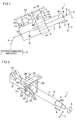
- FIG is a schematic side view of a steering system in an embodiment of the invention;
-
FIG. 2 is a schematic perspective view of the steering system; -
FIG. 3 is a sectional view of the steering system corresponding to a sectional view taken along line III-III inFIG. 1 ; -
FIG. 4 is a schematic exploded perspective view of a tooth locking mechanism; -
FIGS. 5A and 5B are schematic side views of the tooth locking mechanism,FIG. 5A depicts a meshing engagement state, andFIG. 5B depicts a meshing engagement released state; and -
FIG. 6 is a schematic side view of a tooth locking mechanism in another embodiment of the invention. - An embodiment of the invention will be described below in detail with reference to the attached drawings.
FIG. 1 is a schematic side view of asteering system 1 according to an embodiment of the invention. As seen inFIG. 1 , thesteering system 1 includes asteering shaft 3 and asteering operation mechanism 5. An end (axially upper end) of thesteering shaft 3 is coupled to asteering member 2 such as a steering wheel. Thesteering operation mechanism 5 is coupled to thesteering shaft 3 via anintermediate shaft 4 and the like. - The
steering operation mechanism 5 is, for example, a rack-and-pinion mechanism that turns steered wheels (not depicted in the drawings) in conjunction with steering of thesteering member 2. Rotation of thesteering member 2 is transmitted to thesteering operation mechanism 5 via thesteering shaft 3, theintermediate shaft 4, and the like. The rotation transmitted to thesteering operation mechanism 5 is converted into axial movement of a rack shaft not depicted in the drawings. Consequently, the steered wheels are turned. - The
steering shaft 3 has a tubularupper shaft 3U and a tubularlower shaft 3L that are fitted together by, for example, spline fitting or serration fitting so as to be slidable relative to each other. Thesteering member 2 is coupled to an end of theupper shaft 3U. Thesteering shaft 3 can contract and extend in a column axial direction X. Thesteering system 1 includes ahollow column jacket 6 that supports thesteering shaft 3 so as to make thesteering shaft 3 rotatable. Thecolumn jacket 6 includes anupper jacket 7 and alower jacket 8. Theupper jacket 7 is a tubular inner jacket. Thelower jacket 8 is a tubular outer jacket fitted over theupper jacket 7. - The
steering shaft 3 is inserted into thecolumn jacket 6 and rotatably supported by thecolumn jacket 6 via a plurality ofbearings upper jacket 7 is coupled to theupper shaft 3U via thebearing 9 so as to be movable in the column axial direction X in conjunction with theupper shaft 3U. Thelower jacket 8 supports thelower shaft 3L via thebearing 10 so that thelower shaft 3L is rotatable. Theupper jacket 7 moves in the column axial direction X with respect to thelower jacket 8. Consequently, thecolumn jacket 6 can contract and extend in the column axial direction X along with thesteering shaft 3. - The
steering system 1 includes afixed bracket 14, atilt center shaft 15, and acolumn bracket 16. Thefixed bracket 14 is fixed to avehicle body 13. Thetilt center shaft 15 is supported by thefixed bracket 14. Thecolumn bracket 16 is fixed to an outer periphery of thelower jacket 8 and rotatably supported by thetilt center shaft 15. Thecolumn jacket 6 and thesteering shaft 3 can pivot (is tiltable) in a tilt direction Y using, as a support, a tilt center CC that is a central axis of thetilt center shaft 15. - The position of the
steering member 2 can be adjusted by pivoting (tilting) thesteering shaft 3 and thecolumn jacket 6 around the tilt center CC (tilt adjustment). The position of thesteering member 2 can be adjusted by contracting or extending thesteering shaft 3 and thecolumn jacket 6 in the column axial direction X (telescopic adjustment). - The
steering system 1 includes abracket 17 and aclamping mechanism 18. Thebracket 17 includes anattachment plate 24 fixed to thevehicle body 13. Theclamping mechanism 18 achieves tilt locking and telescopic locking by clamping a pair of clampedportions 19 integrated with an upper portion of thelower jacket 8 in the column axial direction X. As depicted inFIG. 1 and FIG. 2 that is a schematic perspective view of thesteering system 1, theclamping mechanism 18 includes aclamping shaft 21 and anoperation lever 20. Theclamping shaft 21 is inserted throughtilting slots 23 in thebracket 17 to clamp the clampedportions 19. Theoperation lever 20 is an operation member that rotates theclamping shaft 21. A central axis C1 of theclamping shaft 21 corresponds to a center of rotation of theoperation lever 20. - As depicted in
FIG. 2 , thelower jacket 8 includes aslit 26 extending downward from its upper end in the column axial direction X. The clampedportions 19 are arranged on opposite sides of theslit 26. Clamping the clampedportions 19 enables thelower jacket 8 to be elastically reduced in diameter.FIG. 3 is a sectional view taken along line III-III inFIG. 1 . As depicted inFIG. 3 , thebracket 17 includes theattachment plate 24 and a pair ofside plates 22. Theattachment plate 24 is attached to thevehicle body 13. Theside plates 22 extend downward from the opposite ends of theattachment plate 24 in the tilt direction Y. - The
lower jacket 8 has aguide groove 27 extending in the column axial direction X. A guidedprotrusion 28 fixed to theupper jacket 7 is fitted in theguide groove 27. Theguide groove 27 allows axial movement of theupper jacket 7 to be guided and regulates rotation of theupper jacket 7 with respect to thelower jacket 8. An end (not depicted in the drawings) of theguide groove 27 in the column axial direction X comes into abutting contact with the guidedprotrusion 28. This prevents theupper jacket 7 from slipping out from thelower jacket 8. - The clamped
portions 19 of thelower jacket 8 are arranged between theside plates 22 and shaped like plates each extending along aninner surface 22a of thecorresponding side plate 22. Theinner surfaces 22a of theside plates 22 each face anouter surface 19a of the corresponding clampedportion 19. In each of the clampedportions 19 of thelower jacket 8, afirst insertion hole 29 is formed which is a circular hole through which the clampingshaft 21 is inserted. During tilt adjustment, the clampingshaft 21, thelower jacket 8, theupper jacket 7, and thesteering shaft 3 move together in the tilt direction Y. - The clamping
shaft 21 is a bolt inserted through the tiltingslots 23 in theside plates 22 of thebracket 17 and through the first insertion holes 29 in the clampedportions 19 of thelower jacket 8. A large-diameter head portion 21a provided at one end of the clampingshaft 21 is fixed to theoperation lever 20 so as to be rotatable together with theoperation lever 20. Theclamping mechanism 18 is interposed between thehead portion 21a of the clampingshaft 21 and one of theside plates 22. Theclamping mechanism 18 further includes a force conversion mechanism 30 that converts an operation torque of theoperation lever 20 into an axial force of the clamping shaft 21 (a clamping force needed to clamp the side plates 22). - The force conversion mechanism 30 includes a
rotation cam 31 and a first clamping member 32. Therotation cam 31 is coupled to theoperation lever 20 so as to be rotatable together with theoperation lever 20. Movement of therotation cam 31 with respect to the clampingshaft 21 is regulated in a clamping shaft direction J that is a direction in which a central axial of the clampingshaft 21 extends. The first clamping member 32 is a non-rotation cam that cam-engages with therotation cam 31 to clamp a corresponding one of theside plates 22. Theclamping mechanism 18 further includes anut 33, asecond clamping member 34, and aninterposition member 35. Thenut 33 is screw-threaded on a threadedportion 21b of the other end of the clampingshaft 21. Thesecond clamping member 34 clamps theother side plate 22. Theinterposition member 35 is interposed between thesecond clamping member 34 and thenut 33. Theinterposition member 35 includes awasher 36 and aneedle roller bearing 37. - The
second clamping member 34 and theinterposition member 35 are interposed between thenut 33 and theother side plate 22 of thebracket 17. Therotation cam 31, the first clamping member 32 (non-rotation cam), thesecond clamping member 34, and theinterposition member 35 are supported by an outer periphery of the clampingshaft 21. The first clamping member 32 (non-rotation cam) and thesecond clamping member 34 have clampingplate portions corresponding side plates 22, andboss portions corresponding tilting slots 23. The fitting between theboss portions corresponding tilting slots 23 regulates rotation of the clampingmembers 32 and 34. - The first clamping member 32 (non-rotation cam) and the
second clamping member 34 are supported by the clampingshaft 21 so as to be movable in the clamping shaft direction J. In conjunction with rotation of theoperation lever 20 in a locking direction, therotation cam 31 rotates with respect to the first clamping member 32 (non-rotation cam). Consequently, the first clamping member 32 is moved in the clamping shaft direction J to clamp theside plates 22 of thebracket 17 between (the clampingplate portions clamping members 32 and 34. - Thus, the
side plates 22 of thebracket 17 clamp the corresponding clampedportions 19 of thelower jacket 8. As a result, movement of thelower jacket 8 in the tilt direction Y is regulated to achieve tilt locking. Both clampedportions 19 are clamped to elastically reduce thelower jacket 8 in diameter to clamp theupper jacket 7. Consequently, movement of theupper jacket 7 in the column axial direction X is regulated to achieve telescopic locking. As described above, theclamping mechanism 18 achieves telescopic locking based on friction between thejackets - As depicted in
FIG. 4 , thesteering system 1 further includes a tooth locking mechanism TL that brings teeth into meshing engagement with one another during clamping by theclamping mechanism 18 in order to stabilize initial restraint in a telescopic direction at the time of a secondary collision (in other words, in order to hold a telescopic position for theupper jacket 7 in an initial stage of the secondary collision). As seen inFIG. 4 andFIG. 5A that is a schematic side view, the tooth locking mechanism TL includes a firsttooth defining member 40, asupport shaft 50, a secondtooth defining member 60, and aninterlocking mechanism 70. The firsttooth defining member 40 hasfirst teeth 41 and moves together with theupper jacket 7 in the column axial direction X. Thesupport shaft 50 is supported bylong grooves 38 in thelower jacket 8 that extend in the column axial direction X. The secondtooth defining member 60 hassecond teeth 65 and is supported by thesupport shaft 50 so as to be rotatable around a central axis C2 of thesupport shaft 50. The interlockingmechanism 70 interlocks rotation of the clampingshaft 21 with rotation of the secondtooth defining member 60. - As depicted in
FIG. 4 , the firsttooth defining member 40 is formed using a plate material extending longitudinally in the column axial direction X and is fixed to an outer peripheral surface of theupper jacket 7 by welding or the like. A recessedgroove 42 extending in the column axial direction X is formed in asurface 40a of the firsttooth defining member 40. The recessedgroove 42 has a pair of inner wall surfaces extending in the column axial direction X and facing each other in the clamping shaft direction J. On the inner wall surfaces, a pair offirst tooth rows 41L is formed such that each of thefirst tooth rows 41L includes a plurality offirst teeth 41 arranged in the column axial direction X. - Tooth tips of the
first teeth 41 of one of thefirst tooth rows 41L face tooth tips of thefirst teeth 41 of the otherfirst tooth row 41L in the clamping shaft direction J. A tooth trace direction D (corresponding to a tooth width direction) of thefirst teeth 41 extends in a depth direction of the recessedgroove 42 so as to be orthogonal both to the column axial direction X and to the clamping shaft direction J. The firsttooth defining member 40 may be fixed to an outer peripheral surface of theupper jacket 7 by bolts or the like not depicted in the drawings. The firsttooth defining member 40 may be formed integrally with theupper jacket 7 using a single material. - A pair of
ends 51 of thesupport shaft 50 is slidably supported in correspondinglong grooves 38 in thelower jacket 8. Thesupport shaft 50 is movable in the column axial direction X while being parallel to the clampingshaft 21. As depicted inFIG. 4 andFIG. 5A , the secondtooth defining member 60 includes abase portion 62, a pair ofarms 63, coupling holes 64, andsecond teeth 65. Thebase portion 62 has afitting hole 61 in which an axiallyintermediate portion 52 of thesupport shaft 50 is fitted such that thebase portion 62 is rotatable together with thesupport shaft 50. Thearms 63 branch from thebase portion 62 in a bifurcated manner and extend in a radial direction of thesupport shaft 50. The coupling holes 64 are formed at respective tip portions of thearms 63. Thesecond teeth 65 are formed on each of thearms 63. - The
second teeth 65 on therespective arms 63 form a pair ofsecond tooth rows 65L each including a plurality ofsecond teeth 65 arranged on a first tooth defining member 40-side surface of thecorresponding arm 63 in a direction in which thecorresponding arm 63 extends. As depicted inFIG. 4 , tooth tips of thesecond teeth 65 of the twosecond tooth rows 65L face laterally outward in the opposite directions. Thesecond teeth 65 of each of thesecond tooth rows 65L can come into meshing engagement with thefirst teeth 41 of the correspondingfirst tooth row 41L in the tooth trace direction D. - The
first tooth rows 41L are arranged on opposite sides in the clamping shaft direction J. The tooth trace direction D is orthogonal to the column axial direction X and to the clamping shaft direction J. This allows suppression of possible tooth jump between thesecond teeth 65 and thefirst teeth 41 at the time of the secondary collision. As depicted inFIG. 4 andFIG. 5A , the interlockingmechanism 70 includes a drivingmember 80 and acoupling shaft 90. The drivingmember 80 rotates together with the clampingshaft 21. Thecoupling shaft 90 couples the secondtooth defining member 60 and the drivingmember 80 together such that the secondtooth defining member 60 and the drivingmember 80 are rotatable, and extends parallel to the clampingshaft 21. - The driving
member 80 includes abase portion 82, anarm 83, and acoupling hole 84. Thebase portion 82 has a fitting hole 81 (spline hole) in which aspline portion 21c on an outer periphery of the clampingshaft 21 is spline-fitted such that thebase portion 82 is rotatable together with the clampingshaft 21. Thearm 83 extends from thebase portion 82 in a radial direction of the clampingshaft 21. Thecoupling hole 84 is formed at a tip portion of thearm 83. Thearm 83 of the drivingmember 80 is arranged between thearms 63 of the secondtooth defining member 60. Thecoupling shaft 90 is inserted through the coupling holes 64 in thearms 63 of the secondtooth defining member 60 and through thecoupling hole 84 in thearm 83 of the drivingmember 80. - In the
coupling hole 84 in thearm 83 of the drivingmember 80, a corresponding portion of acoupling shaft 90 is fitted. Through the coupling holes 64 in thearms 63 of the secondtooth defining member 60, corresponding portions of thecoupling shaft 90 are loosely arranged. Specifically, thecoupling hole 64 is larger in diameter than thecoupling shaft 90 by a predetermined amount. Theoperation lever 20 is rotated in the locking direction to rotate the drivingmember 80 counterclockwise along with the clampingshaft 21 from a state depicted inFIG. 5B to a state depicted inFIG. 5A . The secondtooth defining member 60 coupled to the drivingmember 80 via thecoupling shaft 90 is rotated clockwise around the central axis C2 of thesupport shaft 50. Consequently, thesecond teeth 65 come into meshing engagement with thefirst teeth 41 in the tooth trace direction D (seeFIG. 5A ). This achieves telescopic locking based on tooth locking. - At this time, the weight of the second
tooth defining member 60 acts in a direction in which thesecond teeth 65 are brought into engagement with thefirst teeth 41. Although not depicted in the drawings, the secondtooth defining member 60 or a member interlocked with the second tooth defining member 60 (for example, the driving member 80) may be provided with a bias member that constantly biases the secondtooth defining member 60 in the direction in which the secondtooth defining member 60 is brought into engagement with thefirst teeth 41. For example, inFIG. 5A , a bias member may be provided which rotationally biases the secondtooth defining member 60 around the central axis C2 or a bias member may be provided which rotationally biases the drivingmember 80 around the central axis C1. - In contrast, the
operation lever 20 is rotated in an unlocking direction to rotate the drivingmember 80 clockwise along with the clampingshaft 21 from the state depicted inFIG. 5A to the state depicted inFIG. 5B . The secondtooth defining member 60 coupled to the drivingmember 80 via thecoupling shaft 90 is rotated counterclockwise around the central axis C2 of thesupport shaft 50. Consequently, thesecond teeth 65 are separated from thefirst teeth 41 along the tooth trace direction D to release the meshing engagement (seeFIG. 5B ). This releases the telescopic locking based on tooth locking. - In the present embodiment, when the meshing engagement in the tooth locking mechanism in the meshing engagement state (telescopic locking state) depicted in
FIG. 5A is released (telescopic locking is released), the secondtooth defining member 60, which rotates in conjunction with rotation of the clampingshaft 21 via theinterlocking mechanism 70, acts to separate thesecond teeth 65 from thefirst teeth 41 arranged in the column axial direction X. At this time, as depicted inFIG. 5B , thesecond teeth 65 rotate in a circular-arc-like trajectory around the central axis C2 of thesupport shaft 50, whereas thesupport shaft 50 itself slides through thelong groove 38 formed in thelower jacket 8 toward the clampingshaft 21 in the column axial direction X (rightward inFIG. 5B ). - Thus, the movement trajectory of the
second teeth 65 during release of the meshing engagement is in a direction approximately orthogonal to the column axial direction X (the direction in which thefirst teeth 41 are arranged, and which is indicated by a blank arrow inFIG. 5B and corresponds to the tooth trace direction D of the first teeth 41). Therefore, the meshing engagement between thefirst teeth 41 and thesecond teeth 65 can be easily released. Through the coupling holes 64 in thearms 63 of the secondtooth defining member 60, the corresponding portions of thecoupling shaft 90 are loosely arranged. Therefore, during the release of the meshing engagement, movement of thesupport shaft 50 and the secondtooth defining member 60 in the column axial direction X is permitted by the radial play between thecoupling shaft 90 and the coupling holes 64 in thearms 63 of the secondtooth defining member 60. The meshing engagement can be released as easily as possible. - The invention is not limited to the above-described embodiment. For example, the
long groove 38 in which thesupport shaft 50 is supported may be formed in a member supported by the lower jacket 8 (not depicted in the drawings). The coupling holes 64 in the secondtooth defining member 60 may be fitted over thecoupling shaft 90. A radial play may be provided between thecoupling shaft 90 and thecoupling hole 84 in the drivingmember 80. The tooth trace direction D of thefirst teeth 41 and thesecond teeth 65 may be parallel to the clamping shaft direction J, and thefirst teeth 41 may be brought into meshing engagement with thesecond teeth 65 in a tooth depth direction and the meshing engagement may be released in the tooth depth direction. A singlesecond tooth 65 may be provided in eacharm 63. - The
clamping mechanism 18, theslit 26, and the tooth locking mechanism TL may be arranged below theupper jacket 7 in the tilt direction Y. Thecoupling shaft 90 may be arranged above the clampingshaft 21 in the column axial direction X. Thesupport shaft 50 may be arranged above thecoupling shaft 90 in the column axial direction X. As depicted inFIG. 6 , thesecond tooth rows 65L of the secondtooth defining member 60 may be inclined in a side view. A length DL of tooth traces 65a of the second teeth 65 (corresponding to the tooth width) may increase toward a tip of the second tooth defining member 60 (toward the side opposite to the support shaft 50). In this case, when thesecond teeth 65 of thesecond tooth rows 65L are separated from thefirst teeth 41 to release the meshing engagement, thesecond teeth 65 are sequentially separated starting with thesecond tooth 65 closest to thesupport shaft 50 to release the meshing engagement. This facilitates the separation so that separation performance is enhanced. In contrast, when thesecond teeth 65 are brought into meshing engagement with thefirst teeth 41, the meshing engagement is sequentially performed starting with thesecond teeth 65 of each of thesecond tooth rows 65L that is closest to the tip of the secondtooth defining member 60. This facilitates the meshing engagement so that meshing engagement performance is enhanced. - The
steering system 1 is not limited to the manual type steering system and may be an electric power steering system that applies mechanical power of an electric motor to thesteering shaft 3 to assist steering. Furthermore, various changes may be made to the invention within the scope of the invention recited in the claims.
Claims (2)
- A steering system comprising:a steering shaft configured to contract and extend in a column axial direction;a column jacket including an outer jacket having a slit and a pair of clamped portions arranged on opposite sides of the slit and an inner jacket fitted in the outer jacket, the column jacket being configured to contract and extend in the column axial direction;a clamping mechanism including a clamping shaft supported in clamping shaft insertion holes in the clamped portions and an operation lever that rotates the clamping shaft, the clamping mechanism clamping the clamped portions via the clamping shaft to allow the outer jacket to hold the inner jacket; anda tooth locking mechanism that brings first teeth into meshing engagement with second teeth to achieve telescopic locking during clamping by the clamping mechanism, whereinthe tooth locking mechanism includes:a first tooth defining member having the first teeth such that the first teeth are arranged in the column axial direction and moving together with the inner jacket;a support shaft supported in a long groove formed in the outer jacket or a member supported by the outer jacket and extending in the column axial direction such that the support shaft is slidable in the column axial direction;a second tooth defining member that has the second teeth and that is supported by the support shaft so as to be rotatable around a central axis of the support shaft; andan interlocking mechanism including a driving member that rotates together with the clamping shaft and a coupling shaft that couples the second tooth defining member and the driving member together such that the second tooth defining member and the driving member are rotatable and that is parallel to the clamping shaft, the interlocking mechanism interlocking rotation of the clamping shaft with rotation of the second tooth defining member.
- The steering system according to claim 1, wherein the second tooth defining member and the driving member each include a coupling hole through which the coupling shaft is inserted, and
a radial play is provided between the coupling shaft and the coupling hole in one of the second tooth defining member and the driving member.
Applications Claiming Priority (1)
| Application Number | Priority Date | Filing Date | Title |
|---|---|---|---|
| JP2015072427A JP6504391B2 (en) | 2015-03-31 | 2015-03-31 | Steering device |
Publications (2)
| Publication Number | Publication Date |
|---|---|
| EP3075631A1 true EP3075631A1 (en) | 2016-10-05 |
| EP3075631B1 EP3075631B1 (en) | 2018-08-01 |
Family
ID=55650231
Family Applications (1)
| Application Number | Title | Priority Date | Filing Date |
|---|---|---|---|
| EP16162612.2A Not-in-force EP3075631B1 (en) | 2015-03-31 | 2016-03-29 | Steering system |
Country Status (4)
| Country | Link |
|---|---|
| US (1) | US9663135B2 (en) |
| EP (1) | EP3075631B1 (en) |
| JP (1) | JP6504391B2 (en) |
| CN (1) | CN106004981B (en) |
Families Citing this family (6)
| Publication number | Priority date | Publication date | Assignee | Title |
|---|---|---|---|---|
| US9783221B2 (en) * | 2015-07-29 | 2017-10-10 | Jtekt Corporation | Steering system and tooth member |
| GB201604974D0 (en) * | 2016-03-23 | 2016-05-04 | Trw Das A S | A steering column assembly |
| GB201604976D0 (en) * | 2016-03-23 | 2016-05-04 | Trw Das A S | A steering column assembly |
| GB201604977D0 (en) * | 2016-03-23 | 2016-05-04 | Trw Das A S | A steering column assembly |
| GB201616323D0 (en) * | 2016-09-26 | 2016-11-09 | Trw Limited | A steering column assembly |
| KR20240152681A (en) * | 2023-04-13 | 2024-10-22 | 에이치엘만도 주식회사 | Steering appartus for vehicle |
Citations (2)
| Publication number | Priority date | Publication date | Assignee | Title |
|---|---|---|---|---|
| US20100300238A1 (en) * | 2009-05-29 | 2010-12-02 | Gm Global Technology Operations, Inc. | Energy Absorbing Device for a Collapsible Steering Column Assembly |
| US20140260762A1 (en) * | 2013-03-15 | 2014-09-18 | Steering Solutions Ip Holding Corporation | Crash Release Mechanism for Automotive Steering Column |
Family Cites Families (19)
| Publication number | Priority date | Publication date | Assignee | Title |
|---|---|---|---|---|
| JP2003327133A (en) * | 2002-05-13 | 2003-11-19 | Koyo Seiko Co Ltd | Steering gear |
| US7861615B2 (en) * | 2005-04-19 | 2011-01-04 | Gm Global Technology Operations, Inc. | Adjustable steering column assembly |
| JP2007083936A (en) * | 2005-09-26 | 2007-04-05 | Fuji Kiko Co Ltd | Vehicle steering device |
| CN2923462Y (en) * | 2006-06-27 | 2007-07-18 | 浙江吉利汽车研究院有限公司 | Steering-tubular-column spout connection mechanism |
| JP5030029B2 (en) * | 2009-02-13 | 2012-09-19 | 日本精工株式会社 | Steering column device |
| JP5293381B2 (en) * | 2009-04-28 | 2013-09-18 | 日本精工株式会社 | Telescopic steering device |
| US8555745B2 (en) | 2009-04-20 | 2013-10-15 | Nsk Ltd. | Position adjustment device for steering wheel |
| JP6351009B2 (en) * | 2014-03-24 | 2018-07-04 | 株式会社ジェイテクト | Steering device |
| US9764757B2 (en) * | 2014-06-27 | 2017-09-19 | Steering Solutions Ip Holding Corporation | Steering column energy absorbing rake lock |
| US9545943B2 (en) * | 2014-09-17 | 2017-01-17 | Jtekt Corporation | Steering device |
| JP6493729B2 (en) * | 2014-11-25 | 2019-04-03 | 株式会社ジェイテクト | Steering device |
| JP6429077B2 (en) * | 2015-01-26 | 2018-11-28 | 株式会社ジェイテクト | Steering device |
| JP6403333B2 (en) * | 2015-03-09 | 2018-10-10 | 株式会社ジェイテクト | Steering device |
| JP6410644B2 (en) * | 2015-03-09 | 2018-10-24 | 株式会社ジェイテクト | Steering device |
| JP6410645B2 (en) * | 2015-03-09 | 2018-10-24 | 株式会社ジェイテクト | Steering device |
| JP6508518B2 (en) * | 2015-03-31 | 2019-05-08 | 株式会社ジェイテクト | Steering device |
| US9428215B1 (en) * | 2015-03-31 | 2016-08-30 | Jtekt Corporation | Steering system |
| US9623897B2 (en) * | 2015-03-31 | 2017-04-18 | Jtekt Corporation | Steering system |
| US9783221B2 (en) * | 2015-07-29 | 2017-10-10 | Jtekt Corporation | Steering system and tooth member |
-
2015
- 2015-03-31 JP JP2015072427A patent/JP6504391B2/en not_active Expired - Fee Related
-
2016
- 2016-03-25 US US15/081,363 patent/US9663135B2/en not_active Expired - Fee Related
- 2016-03-29 EP EP16162612.2A patent/EP3075631B1/en not_active Not-in-force
- 2016-03-29 CN CN201610188503.5A patent/CN106004981B/en not_active Expired - Fee Related
Patent Citations (2)
| Publication number | Priority date | Publication date | Assignee | Title |
|---|---|---|---|---|
| US20100300238A1 (en) * | 2009-05-29 | 2010-12-02 | Gm Global Technology Operations, Inc. | Energy Absorbing Device for a Collapsible Steering Column Assembly |
| US20140260762A1 (en) * | 2013-03-15 | 2014-09-18 | Steering Solutions Ip Holding Corporation | Crash Release Mechanism for Automotive Steering Column |
Also Published As
| Publication number | Publication date |
|---|---|
| CN106004981B (en) | 2019-11-01 |
| CN106004981A (en) | 2016-10-12 |
| US9663135B2 (en) | 2017-05-30 |
| JP2016190585A (en) | 2016-11-10 |
| EP3075631B1 (en) | 2018-08-01 |
| US20160288817A1 (en) | 2016-10-06 |
| JP6504391B2 (en) | 2019-04-24 |
Similar Documents
| Publication | Publication Date | Title |
|---|---|---|
| EP3075630B1 (en) | Steering system | |
| US9623897B2 (en) | Steering system | |
| EP3075631B1 (en) | Steering system | |
| US9783222B2 (en) | Steering system | |
| US9604663B2 (en) | Steering system | |
| US9840269B2 (en) | Steering system | |
| US9840270B2 (en) | Steering system | |
| JP6270140B2 (en) | Steering device | |
| US9783221B2 (en) | Steering system and tooth member | |
| EP2896546B1 (en) | Steering apparatus | |
| US9637160B2 (en) | Steering system | |
| JP5516543B2 (en) | Steering device | |
| JP2016193711A (en) | Steering device | |
| JP6440536B2 (en) | Steering device | |
| JP2014201268A (en) | Steering device | |
| JP2016190586A (en) | Steering device | |
| JP2010241187A (en) | Steering column device |
Legal Events
| Date | Code | Title | Description |
|---|---|---|---|
| PUAI | Public reference made under article 153(3) epc to a published international application that has entered the european phase |
Free format text: ORIGINAL CODE: 0009012 |
|
| AK | Designated contracting states |
Kind code of ref document: A1 Designated state(s): AL AT BE BG CH CY CZ DE DK EE ES FI FR GB GR HR HU IE IS IT LI LT LU LV MC MK MT NL NO PL PT RO RS SE SI SK SM TR |
|
| AX | Request for extension of the european patent |
Extension state: BA ME |
|
| STAA | Information on the status of an ep patent application or granted ep patent |
Free format text: STATUS: REQUEST FOR EXAMINATION WAS MADE |
|
| 17P | Request for examination filed |
Effective date: 20170405 |
|
| RBV | Designated contracting states (corrected) |
Designated state(s): AL AT BE BG CH CY CZ DE DK EE ES FI FR GB GR HR HU IE IS IT LI LT LU LV MC MK MT NL NO PL PT RO RS SE SI SK SM TR |
|
| GRAP | Despatch of communication of intention to grant a patent |
Free format text: ORIGINAL CODE: EPIDOSNIGR1 |
|
| STAA | Information on the status of an ep patent application or granted ep patent |
Free format text: STATUS: GRANT OF PATENT IS INTENDED |
|
| INTG | Intention to grant announced |
Effective date: 20180215 |
|
| GRAS | Grant fee paid |
Free format text: ORIGINAL CODE: EPIDOSNIGR3 |
|
| GRAA | (expected) grant |
Free format text: ORIGINAL CODE: 0009210 |
|
| STAA | Information on the status of an ep patent application or granted ep patent |
Free format text: STATUS: THE PATENT HAS BEEN GRANTED |
|
| RIN1 | Information on inventor provided before grant (corrected) |
Inventor name: SAKUDA, MASAYOSHI Inventor name: MYOHOJI, YU Inventor name: NAGATANI, ATSUMUNE |
|
| AK | Designated contracting states |
Kind code of ref document: B1 Designated state(s): AL AT BE BG CH CY CZ DE DK EE ES FI FR GB GR HR HU IE IS IT LI LT LU LV MC MK MT NL NO PL PT RO RS SE SI SK SM TR |
|
| REG | Reference to a national code |
Ref country code: GB Ref legal event code: FG4D |
|
| REG | Reference to a national code |
Ref country code: CH Ref legal event code: EP Ref country code: AT Ref legal event code: REF Ref document number: 1023928 Country of ref document: AT Kind code of ref document: T Effective date: 20180815 |
|
| REG | Reference to a national code |
Ref country code: IE Ref legal event code: FG4D |
|
| REG | Reference to a national code |
Ref country code: DE Ref legal event code: R096 Ref document number: 602016004378 Country of ref document: DE |
|
| REG | Reference to a national code |
Ref country code: NL Ref legal event code: MP Effective date: 20180801 |
|
| REG | Reference to a national code |
Ref country code: LT Ref legal event code: MG4D |
|
| REG | Reference to a national code |
Ref country code: AT Ref legal event code: MK05 Ref document number: 1023928 Country of ref document: AT Kind code of ref document: T Effective date: 20180801 |
|
| PG25 | Lapsed in a contracting state [announced via postgrant information from national office to epo] |
Ref country code: SE Free format text: LAPSE BECAUSE OF FAILURE TO SUBMIT A TRANSLATION OF THE DESCRIPTION OR TO PAY THE FEE WITHIN THE PRESCRIBED TIME-LIMIT Effective date: 20180801 Ref country code: BG Free format text: LAPSE BECAUSE OF FAILURE TO SUBMIT A TRANSLATION OF THE DESCRIPTION OR TO PAY THE FEE WITHIN THE PRESCRIBED TIME-LIMIT Effective date: 20181101 Ref country code: PL Free format text: LAPSE BECAUSE OF FAILURE TO SUBMIT A TRANSLATION OF THE DESCRIPTION OR TO PAY THE FEE WITHIN THE PRESCRIBED TIME-LIMIT Effective date: 20180801 Ref country code: NL Free format text: LAPSE BECAUSE OF FAILURE TO SUBMIT A TRANSLATION OF THE DESCRIPTION OR TO PAY THE FEE WITHIN THE PRESCRIBED TIME-LIMIT Effective date: 20180801 Ref country code: LT Free format text: LAPSE BECAUSE OF FAILURE TO SUBMIT A TRANSLATION OF THE DESCRIPTION OR TO PAY THE FEE WITHIN THE PRESCRIBED TIME-LIMIT Effective date: 20180801 Ref country code: FI Free format text: LAPSE BECAUSE OF FAILURE TO SUBMIT A TRANSLATION OF THE DESCRIPTION OR TO PAY THE FEE WITHIN THE PRESCRIBED TIME-LIMIT Effective date: 20180801 Ref country code: RS Free format text: LAPSE BECAUSE OF FAILURE TO SUBMIT A TRANSLATION OF THE DESCRIPTION OR TO PAY THE FEE WITHIN THE PRESCRIBED TIME-LIMIT Effective date: 20180801 Ref country code: IS Free format text: LAPSE BECAUSE OF FAILURE TO SUBMIT A TRANSLATION OF THE DESCRIPTION OR TO PAY THE FEE WITHIN THE PRESCRIBED TIME-LIMIT Effective date: 20181201 Ref country code: AT Free format text: LAPSE BECAUSE OF FAILURE TO SUBMIT A TRANSLATION OF THE DESCRIPTION OR TO PAY THE FEE WITHIN THE PRESCRIBED TIME-LIMIT Effective date: 20180801 Ref country code: GR Free format text: LAPSE BECAUSE OF FAILURE TO SUBMIT A TRANSLATION OF THE DESCRIPTION OR TO PAY THE FEE WITHIN THE PRESCRIBED TIME-LIMIT Effective date: 20181102 Ref country code: NO Free format text: LAPSE BECAUSE OF FAILURE TO SUBMIT A TRANSLATION OF THE DESCRIPTION OR TO PAY THE FEE WITHIN THE PRESCRIBED TIME-LIMIT Effective date: 20181101 |
|
| PG25 | Lapsed in a contracting state [announced via postgrant information from national office to epo] |
Ref country code: HR Free format text: LAPSE BECAUSE OF FAILURE TO SUBMIT A TRANSLATION OF THE DESCRIPTION OR TO PAY THE FEE WITHIN THE PRESCRIBED TIME-LIMIT Effective date: 20180801 Ref country code: LV Free format text: LAPSE BECAUSE OF FAILURE TO SUBMIT A TRANSLATION OF THE DESCRIPTION OR TO PAY THE FEE WITHIN THE PRESCRIBED TIME-LIMIT Effective date: 20180801 Ref country code: AL Free format text: LAPSE BECAUSE OF FAILURE TO SUBMIT A TRANSLATION OF THE DESCRIPTION OR TO PAY THE FEE WITHIN THE PRESCRIBED TIME-LIMIT Effective date: 20180801 |
|
| PG25 | Lapsed in a contracting state [announced via postgrant information from national office to epo] |
Ref country code: EE Free format text: LAPSE BECAUSE OF FAILURE TO SUBMIT A TRANSLATION OF THE DESCRIPTION OR TO PAY THE FEE WITHIN THE PRESCRIBED TIME-LIMIT Effective date: 20180801 Ref country code: IT Free format text: LAPSE BECAUSE OF FAILURE TO SUBMIT A TRANSLATION OF THE DESCRIPTION OR TO PAY THE FEE WITHIN THE PRESCRIBED TIME-LIMIT Effective date: 20180801 Ref country code: CZ Free format text: LAPSE BECAUSE OF FAILURE TO SUBMIT A TRANSLATION OF THE DESCRIPTION OR TO PAY THE FEE WITHIN THE PRESCRIBED TIME-LIMIT Effective date: 20180801 Ref country code: RO Free format text: LAPSE BECAUSE OF FAILURE TO SUBMIT A TRANSLATION OF THE DESCRIPTION OR TO PAY THE FEE WITHIN THE PRESCRIBED TIME-LIMIT Effective date: 20180801 Ref country code: ES Free format text: LAPSE BECAUSE OF FAILURE TO SUBMIT A TRANSLATION OF THE DESCRIPTION OR TO PAY THE FEE WITHIN THE PRESCRIBED TIME-LIMIT Effective date: 20180801 |
|
| REG | Reference to a national code |
Ref country code: DE Ref legal event code: R097 Ref document number: 602016004378 Country of ref document: DE |
|
| PG25 | Lapsed in a contracting state [announced via postgrant information from national office to epo] |
Ref country code: SK Free format text: LAPSE BECAUSE OF FAILURE TO SUBMIT A TRANSLATION OF THE DESCRIPTION OR TO PAY THE FEE WITHIN THE PRESCRIBED TIME-LIMIT Effective date: 20180801 Ref country code: SM Free format text: LAPSE BECAUSE OF FAILURE TO SUBMIT A TRANSLATION OF THE DESCRIPTION OR TO PAY THE FEE WITHIN THE PRESCRIBED TIME-LIMIT Effective date: 20180801 Ref country code: DK Free format text: LAPSE BECAUSE OF FAILURE TO SUBMIT A TRANSLATION OF THE DESCRIPTION OR TO PAY THE FEE WITHIN THE PRESCRIBED TIME-LIMIT Effective date: 20180801 |
|
| PLBE | No opposition filed within time limit |
Free format text: ORIGINAL CODE: 0009261 |
|
| STAA | Information on the status of an ep patent application or granted ep patent |
Free format text: STATUS: NO OPPOSITION FILED WITHIN TIME LIMIT |
|
| 26N | No opposition filed |
Effective date: 20190503 |
|
| PG25 | Lapsed in a contracting state [announced via postgrant information from national office to epo] |
Ref country code: SI Free format text: LAPSE BECAUSE OF FAILURE TO SUBMIT A TRANSLATION OF THE DESCRIPTION OR TO PAY THE FEE WITHIN THE PRESCRIBED TIME-LIMIT Effective date: 20180801 |
|
| PG25 | Lapsed in a contracting state [announced via postgrant information from national office to epo] |
Ref country code: MC Free format text: LAPSE BECAUSE OF FAILURE TO SUBMIT A TRANSLATION OF THE DESCRIPTION OR TO PAY THE FEE WITHIN THE PRESCRIBED TIME-LIMIT Effective date: 20180801 |
|
| REG | Reference to a national code |
Ref country code: CH Ref legal event code: PL |
|
| PG25 | Lapsed in a contracting state [announced via postgrant information from national office to epo] |
Ref country code: LU Free format text: LAPSE BECAUSE OF NON-PAYMENT OF DUE FEES Effective date: 20190329 |
|
| REG | Reference to a national code |
Ref country code: BE Ref legal event code: MM Effective date: 20190331 |
|
| PG25 | Lapsed in a contracting state [announced via postgrant information from national office to epo] |
Ref country code: LI Free format text: LAPSE BECAUSE OF NON-PAYMENT OF DUE FEES Effective date: 20190331 Ref country code: CH Free format text: LAPSE BECAUSE OF NON-PAYMENT OF DUE FEES Effective date: 20190331 Ref country code: IE Free format text: LAPSE BECAUSE OF NON-PAYMENT OF DUE FEES Effective date: 20190329 |
|
| PG25 | Lapsed in a contracting state [announced via postgrant information from national office to epo] |
Ref country code: BE Free format text: LAPSE BECAUSE OF NON-PAYMENT OF DUE FEES Effective date: 20190331 |
|
| PG25 | Lapsed in a contracting state [announced via postgrant information from national office to epo] |
Ref country code: TR Free format text: LAPSE BECAUSE OF FAILURE TO SUBMIT A TRANSLATION OF THE DESCRIPTION OR TO PAY THE FEE WITHIN THE PRESCRIBED TIME-LIMIT Effective date: 20180801 |
|
| PG25 | Lapsed in a contracting state [announced via postgrant information from national office to epo] |
Ref country code: MT Free format text: LAPSE BECAUSE OF NON-PAYMENT OF DUE FEES Effective date: 20190329 Ref country code: PT Free format text: LAPSE BECAUSE OF FAILURE TO SUBMIT A TRANSLATION OF THE DESCRIPTION OR TO PAY THE FEE WITHIN THE PRESCRIBED TIME-LIMIT Effective date: 20181201 |
|
| GBPC | Gb: european patent ceased through non-payment of renewal fee |
Effective date: 20200329 |
|
| PG25 | Lapsed in a contracting state [announced via postgrant information from national office to epo] |
Ref country code: GB Free format text: LAPSE BECAUSE OF NON-PAYMENT OF DUE FEES Effective date: 20200329 |
|
| PGFP | Annual fee paid to national office [announced via postgrant information from national office to epo] |
Ref country code: FR Payment date: 20210210 Year of fee payment: 6 |
|
| PG25 | Lapsed in a contracting state [announced via postgrant information from national office to epo] |
Ref country code: CY Free format text: LAPSE BECAUSE OF FAILURE TO SUBMIT A TRANSLATION OF THE DESCRIPTION OR TO PAY THE FEE WITHIN THE PRESCRIBED TIME-LIMIT Effective date: 20180801 |
|
| PGFP | Annual fee paid to national office [announced via postgrant information from national office to epo] |
Ref country code: DE Payment date: 20210316 Year of fee payment: 6 |
|
| PG25 | Lapsed in a contracting state [announced via postgrant information from national office to epo] |
Ref country code: HU Free format text: LAPSE BECAUSE OF FAILURE TO SUBMIT A TRANSLATION OF THE DESCRIPTION OR TO PAY THE FEE WITHIN THE PRESCRIBED TIME-LIMIT; INVALID AB INITIO Effective date: 20160329 |
|
| PG25 | Lapsed in a contracting state [announced via postgrant information from national office to epo] |
Ref country code: MK Free format text: LAPSE BECAUSE OF FAILURE TO SUBMIT A TRANSLATION OF THE DESCRIPTION OR TO PAY THE FEE WITHIN THE PRESCRIBED TIME-LIMIT Effective date: 20180801 |
|
| REG | Reference to a national code |
Ref country code: DE Ref legal event code: R119 Ref document number: 602016004378 Country of ref document: DE |
|
| PG25 | Lapsed in a contracting state [announced via postgrant information from national office to epo] |
Ref country code: FR Free format text: LAPSE BECAUSE OF NON-PAYMENT OF DUE FEES Effective date: 20220331 Ref country code: DE Free format text: LAPSE BECAUSE OF NON-PAYMENT OF DUE FEES Effective date: 20221001 |