EP3075521A1 - Cloth bonding device - Google Patents
Cloth bonding device Download PDFInfo
- Publication number
- EP3075521A1 EP3075521A1 EP16161713.9A EP16161713A EP3075521A1 EP 3075521 A1 EP3075521 A1 EP 3075521A1 EP 16161713 A EP16161713 A EP 16161713A EP 3075521 A1 EP3075521 A1 EP 3075521A1
- Authority
- EP
- European Patent Office
- Prior art keywords
- drive mechanism
- nozzle
- base
- cloth
- bonding device
- Prior art date
- Legal status (The legal status is an assumption and is not a legal conclusion. Google has not performed a legal analysis and makes no representation as to the accuracy of the status listed.)
- Granted
Links
- 239000004744 fabric Substances 0.000 title claims abstract description 129
- 230000007246 mechanism Effects 0.000 claims abstract description 154
- 239000000853 adhesive Substances 0.000 claims description 45
- 230000001070 adhesive effect Effects 0.000 claims description 45
- 238000003780 insertion Methods 0.000 claims description 34
- 230000037431 insertion Effects 0.000 claims description 34
- 230000005540 biological transmission Effects 0.000 claims description 12
- 238000011144 upstream manufacturing Methods 0.000 claims description 2
- 238000007599 discharging Methods 0.000 claims 1
- 238000000034 method Methods 0.000 description 11
- 230000008569 process Effects 0.000 description 8
- 230000000630 rising effect Effects 0.000 description 6
- 238000012423 maintenance Methods 0.000 description 5
- 230000008878 coupling Effects 0.000 description 3
- 238000010168 coupling process Methods 0.000 description 3
- 238000005859 coupling reaction Methods 0.000 description 3
- 239000004831 Hot glue Substances 0.000 description 2
- 238000005452 bending Methods 0.000 description 1
- 230000008859 change Effects 0.000 description 1
- 239000000155 melt Substances 0.000 description 1
- 238000012986 modification Methods 0.000 description 1
- 230000004048 modification Effects 0.000 description 1
Images




Classifications
-
- B—PERFORMING OPERATIONS; TRANSPORTING
- B29—WORKING OF PLASTICS; WORKING OF SUBSTANCES IN A PLASTIC STATE IN GENERAL
- B29C—SHAPING OR JOINING OF PLASTICS; SHAPING OF MATERIAL IN A PLASTIC STATE, NOT OTHERWISE PROVIDED FOR; AFTER-TREATMENT OF THE SHAPED PRODUCTS, e.g. REPAIRING
- B29C66/00—General aspects of processes or apparatus for joining preformed parts
- B29C66/80—General aspects of machine operations or constructions and parts thereof
- B29C66/84—Specific machine types or machines suitable for specific applications
- B29C66/845—C-clamp type or sewing machine type
-
- B—PERFORMING OPERATIONS; TRANSPORTING
- B29—WORKING OF PLASTICS; WORKING OF SUBSTANCES IN A PLASTIC STATE IN GENERAL
- B29C—SHAPING OR JOINING OF PLASTICS; SHAPING OF MATERIAL IN A PLASTIC STATE, NOT OTHERWISE PROVIDED FOR; AFTER-TREATMENT OF THE SHAPED PRODUCTS, e.g. REPAIRING
- B29C65/00—Joining or sealing of preformed parts, e.g. welding of plastics materials; Apparatus therefor
- B29C65/48—Joining or sealing of preformed parts, e.g. welding of plastics materials; Apparatus therefor using adhesives, i.e. using supplementary joining material; solvent bonding
- B29C65/4805—Joining or sealing of preformed parts, e.g. welding of plastics materials; Apparatus therefor using adhesives, i.e. using supplementary joining material; solvent bonding characterised by the type of adhesives
- B29C65/481—Non-reactive adhesives, e.g. physically hardening adhesives
- B29C65/4815—Hot melt adhesives, e.g. thermoplastic adhesives
-
- B—PERFORMING OPERATIONS; TRANSPORTING
- B29—WORKING OF PLASTICS; WORKING OF SUBSTANCES IN A PLASTIC STATE IN GENERAL
- B29C—SHAPING OR JOINING OF PLASTICS; SHAPING OF MATERIAL IN A PLASTIC STATE, NOT OTHERWISE PROVIDED FOR; AFTER-TREATMENT OF THE SHAPED PRODUCTS, e.g. REPAIRING
- B29C65/00—Joining or sealing of preformed parts, e.g. welding of plastics materials; Apparatus therefor
- B29C65/48—Joining or sealing of preformed parts, e.g. welding of plastics materials; Apparatus therefor using adhesives, i.e. using supplementary joining material; solvent bonding
- B29C65/52—Joining or sealing of preformed parts, e.g. welding of plastics materials; Apparatus therefor using adhesives, i.e. using supplementary joining material; solvent bonding characterised by the way of applying the adhesive
- B29C65/524—Joining or sealing of preformed parts, e.g. welding of plastics materials; Apparatus therefor using adhesives, i.e. using supplementary joining material; solvent bonding characterised by the way of applying the adhesive by applying the adhesive from an outlet device in contact with, or almost in contact with, the surface of the part to be joined
-
- B—PERFORMING OPERATIONS; TRANSPORTING
- B29—WORKING OF PLASTICS; WORKING OF SUBSTANCES IN A PLASTIC STATE IN GENERAL
- B29C—SHAPING OR JOINING OF PLASTICS; SHAPING OF MATERIAL IN A PLASTIC STATE, NOT OTHERWISE PROVIDED FOR; AFTER-TREATMENT OF THE SHAPED PRODUCTS, e.g. REPAIRING
- B29C66/00—General aspects of processes or apparatus for joining preformed parts
- B29C66/01—General aspects dealing with the joint area or with the area to be joined
- B29C66/05—Particular design of joint configurations
- B29C66/10—Particular design of joint configurations particular design of the joint cross-sections
- B29C66/11—Joint cross-sections comprising a single joint-segment, i.e. one of the parts to be joined comprising a single joint-segment in the joint cross-section
- B29C66/112—Single lapped joints
- B29C66/1122—Single lap to lap joints, i.e. overlap joints
-
- B—PERFORMING OPERATIONS; TRANSPORTING
- B29—WORKING OF PLASTICS; WORKING OF SUBSTANCES IN A PLASTIC STATE IN GENERAL
- B29C—SHAPING OR JOINING OF PLASTICS; SHAPING OF MATERIAL IN A PLASTIC STATE, NOT OTHERWISE PROVIDED FOR; AFTER-TREATMENT OF THE SHAPED PRODUCTS, e.g. REPAIRING
- B29C66/00—General aspects of processes or apparatus for joining preformed parts
- B29C66/40—General aspects of joining substantially flat articles, e.g. plates, sheets or web-like materials; Making flat seams in tubular or hollow articles; Joining single elements to substantially flat surfaces
- B29C66/41—Joining substantially flat articles ; Making flat seams in tubular or hollow articles
- B29C66/43—Joining a relatively small portion of the surface of said articles
-
- B—PERFORMING OPERATIONS; TRANSPORTING
- B29—WORKING OF PLASTICS; WORKING OF SUBSTANCES IN A PLASTIC STATE IN GENERAL
- B29C—SHAPING OR JOINING OF PLASTICS; SHAPING OF MATERIAL IN A PLASTIC STATE, NOT OTHERWISE PROVIDED FOR; AFTER-TREATMENT OF THE SHAPED PRODUCTS, e.g. REPAIRING
- B29C66/00—General aspects of processes or apparatus for joining preformed parts
- B29C66/70—General aspects of processes or apparatus for joining preformed parts characterised by the composition, physical properties or the structure of the material of the parts to be joined; Joining with non-plastics material
- B29C66/72—General aspects of processes or apparatus for joining preformed parts characterised by the composition, physical properties or the structure of the material of the parts to be joined; Joining with non-plastics material characterised by the structure of the material of the parts to be joined
- B29C66/729—Textile or other fibrous material made from plastics
-
- B—PERFORMING OPERATIONS; TRANSPORTING
- B29—WORKING OF PLASTICS; WORKING OF SUBSTANCES IN A PLASTIC STATE IN GENERAL
- B29C—SHAPING OR JOINING OF PLASTICS; SHAPING OF MATERIAL IN A PLASTIC STATE, NOT OTHERWISE PROVIDED FOR; AFTER-TREATMENT OF THE SHAPED PRODUCTS, e.g. REPAIRING
- B29C66/00—General aspects of processes or apparatus for joining preformed parts
- B29C66/80—General aspects of machine operations or constructions and parts thereof
- B29C66/81—General aspects of the pressing elements, i.e. the elements applying pressure on the parts to be joined in the area to be joined, e.g. the welding jaws or clamps
- B29C66/816—General aspects of the pressing elements, i.e. the elements applying pressure on the parts to be joined in the area to be joined, e.g. the welding jaws or clamps characterised by the mounting of the pressing elements, e.g. of the welding jaws or clamps
- B29C66/8167—Quick change joining tools or surfaces
-
- B—PERFORMING OPERATIONS; TRANSPORTING
- B29—WORKING OF PLASTICS; WORKING OF SUBSTANCES IN A PLASTIC STATE IN GENERAL
- B29C—SHAPING OR JOINING OF PLASTICS; SHAPING OF MATERIAL IN A PLASTIC STATE, NOT OTHERWISE PROVIDED FOR; AFTER-TREATMENT OF THE SHAPED PRODUCTS, e.g. REPAIRING
- B29C66/00—General aspects of processes or apparatus for joining preformed parts
- B29C66/80—General aspects of machine operations or constructions and parts thereof
- B29C66/83—General aspects of machine operations or constructions and parts thereof characterised by the movement of the joining or pressing tools
- B29C66/834—General aspects of machine operations or constructions and parts thereof characterised by the movement of the joining or pressing tools moving with the parts to be joined
- B29C66/8341—Roller, cylinder or drum types; Band or belt types; Ball types
- B29C66/83411—Roller, cylinder or drum types
- B29C66/83413—Roller, cylinder or drum types cooperating rollers, cylinders or drums
-
- B—PERFORMING OPERATIONS; TRANSPORTING
- B29—WORKING OF PLASTICS; WORKING OF SUBSTANCES IN A PLASTIC STATE IN GENERAL
- B29C—SHAPING OR JOINING OF PLASTICS; SHAPING OF MATERIAL IN A PLASTIC STATE, NOT OTHERWISE PROVIDED FOR; AFTER-TREATMENT OF THE SHAPED PRODUCTS, e.g. REPAIRING
- B29C66/00—General aspects of processes or apparatus for joining preformed parts
- B29C66/80—General aspects of machine operations or constructions and parts thereof
- B29C66/87—Auxiliary operations or devices
- B29C66/876—Maintenance or cleaning
-
- B—PERFORMING OPERATIONS; TRANSPORTING
- B29—WORKING OF PLASTICS; WORKING OF SUBSTANCES IN A PLASTIC STATE IN GENERAL
- B29C—SHAPING OR JOINING OF PLASTICS; SHAPING OF MATERIAL IN A PLASTIC STATE, NOT OTHERWISE PROVIDED FOR; AFTER-TREATMENT OF THE SHAPED PRODUCTS, e.g. REPAIRING
- B29C66/00—General aspects of processes or apparatus for joining preformed parts
- B29C66/80—General aspects of machine operations or constructions and parts thereof
- B29C66/82—Pressure application arrangements, e.g. transmission or actuating mechanisms for joining tools or clamps
- B29C66/822—Transmission mechanisms
- B29C66/8221—Scissor or lever mechanisms, i.e. involving a pivot point
-
- B—PERFORMING OPERATIONS; TRANSPORTING
- B29—WORKING OF PLASTICS; WORKING OF SUBSTANCES IN A PLASTIC STATE IN GENERAL
- B29C—SHAPING OR JOINING OF PLASTICS; SHAPING OF MATERIAL IN A PLASTIC STATE, NOT OTHERWISE PROVIDED FOR; AFTER-TREATMENT OF THE SHAPED PRODUCTS, e.g. REPAIRING
- B29C66/00—General aspects of processes or apparatus for joining preformed parts
- B29C66/80—General aspects of machine operations or constructions and parts thereof
- B29C66/82—Pressure application arrangements, e.g. transmission or actuating mechanisms for joining tools or clamps
- B29C66/822—Transmission mechanisms
- B29C66/8226—Cam mechanisms; Wedges; Eccentric mechanisms
- B29C66/82263—Follower pin or roller cooperating with a groove
-
- B—PERFORMING OPERATIONS; TRANSPORTING
- B29—WORKING OF PLASTICS; WORKING OF SUBSTANCES IN A PLASTIC STATE IN GENERAL
- B29C—SHAPING OR JOINING OF PLASTICS; SHAPING OF MATERIAL IN A PLASTIC STATE, NOT OTHERWISE PROVIDED FOR; AFTER-TREATMENT OF THE SHAPED PRODUCTS, e.g. REPAIRING
- B29C66/00—General aspects of processes or apparatus for joining preformed parts
- B29C66/80—General aspects of machine operations or constructions and parts thereof
- B29C66/82—Pressure application arrangements, e.g. transmission or actuating mechanisms for joining tools or clamps
- B29C66/822—Transmission mechanisms
- B29C66/8226—Cam mechanisms; Wedges; Eccentric mechanisms
- B29C66/82265—Eccentric mechanisms
-
- B—PERFORMING OPERATIONS; TRANSPORTING
- B29—WORKING OF PLASTICS; WORKING OF SUBSTANCES IN A PLASTIC STATE IN GENERAL
- B29C—SHAPING OR JOINING OF PLASTICS; SHAPING OF MATERIAL IN A PLASTIC STATE, NOT OTHERWISE PROVIDED FOR; AFTER-TREATMENT OF THE SHAPED PRODUCTS, e.g. REPAIRING
- B29C66/00—General aspects of processes or apparatus for joining preformed parts
- B29C66/80—General aspects of machine operations or constructions and parts thereof
- B29C66/83—General aspects of machine operations or constructions and parts thereof characterised by the movement of the joining or pressing tools
- B29C66/832—Reciprocating joining or pressing tools
- B29C66/8324—Joining or pressing tools pivoting around one axis
Definitions
- the present invention relates to a cloth bonding device.
- a cloth bonding device discharges an adhesive from a nozzle and the adhesive sticks to a lower cloth. With the adhesive sticking to the lower cloth, the cloth bonding device clamps an upper cloth and the lower cloth between an upper feed roller and a lower feed roller, then presses and feeds the upper cloth and the lower cloth to bond them together.
- a bonding process of the cloth bonding device varies according to the positions in which the upper cloth and the lower cloth are placed.
- the nozzle of the cloth bonding device can be replaced to fit the bonding process.
- a cloth bonding device that is described in Japanese Laid-Open Patent Publication No. 2010-270416 includes a base portion, a pillar portion, an arm portion, and a support portion. The base portion supports the pillar portion, and the pillar portion supports the arm portion.
- the lower feed roller is supported by the base portion, and the upper feed roller is supported by the arm portion.
- the arm portion supports the support portion such that the support portion can be mounted and removed.
- the support portion supports the nozzle and is able to swing in relation to the arm portion.
- the nozzle can be replaced by another nozzle that fits the bonding process of the cloth bonding device and that projects in a different direction from the support portion.
- the positions of the upper feed roller and the lower feed roller do not change in relation to the direction in which the nozzle extends. It is necessary for the position of the nozzle to remain the same in relation to the upper feed roller and the lower feed roller, no matter which one of nozzles that project in different directions from the support portion is mounted in the cloth bonding device. Therefore, the support portion includes a first support portion and a second support portion and supports the nozzle such that the position of the nozzle remains the same in relation to the upper feed roller and the lower feed roller, no matter which one of the nozzles that project in different directions from the support portion is mounted. When replacing nozzle, an operator must replace one of the first support portion and the second support portion with the other. Therefore, the nozzle replacement operation is sometimes burdensome.
- the cloth bonding device includes a base portion, a pillar portion, an arm portion, an upper roller, a lower roller, a nozzle, an upper drive mechanism, an upper mounting base, a guide portion, and a first fixing portion.
- the pillar portion extends upward from the base portion.
- the arm portion extends from the pillar portion and is disposed opposite the base portion.
- the upper roller feeds a cloth.
- the lower roller faces the upper roller and is disposed below the cloth.
- the lower roller clamps the cloth against the upper roller and feeds the cloth in a feed direction by operating in coordination with the upper roller.
- the nozzle can be mounted on and removed from a support body that is provided on the arm portion. The nozzle discharges an adhesive onto the cloth on upstream of the lower roller and the upper roller in the feed direction.
- the upper drive mechanism supports the upper roller and rotationally drives the upper roller.
- the upper mounting base is provided on the arm portion, and the upper drive mechanism is fixed to the upper mounting base.
- the guide portion is provided on the upper mounting base and extends in a specified direction. The guide portion guides the upper drive mechanism in the specified direction. The specified direction is parallel to the direction in which the arm portion extends.
- the first fixing portion fixes the upper drive mechanism, which is guided by the guide portion, in one of fixing positions that are lined up in the specified direction. Because an operator is able to fix the upper drive mechanism to the upper mounting base in any one of the fixing positions, it is not necessary to replace the support body when the nozzle is replaced in accordance with the bonding process of the cloth bonding device.
- the cloth bonding device is able to simplify the operation of replacing the nozzle in accordance with the bonding process.
- the upper drive mechanism moves easily in the specified direction along the guide portion. Therefore, the cloth bonding device easily moves the upper drive mechanism in the specified direction and can stabilize the fixing position of the upper drive mechanism in relation to the upper mounting base.
- the first fixing portion may include a through-hole, a fastening member, and fastening holes.
- the fastening holes are provided in the upper mounting base and discretely disposed along the specified direction.
- the through-hole is provided in the upper drive mechanism and disposed opposite at least one of the fastening holes.
- the fastening member is inserted through the through-hole and tightened into one of the fastening holes.
- the operator inserts the fastening member through the through-hole and tightens it into the one of the fastening holes. Therefore, the cloth bonding device is able to fix the upper drive mechanism securely to the upper mounting base.
- the through-hole may also be an oblong hole having a long axis extending in the specified direction.
- the through-hole is easily disposed opposite one of the fastening holes. Therefore, the cloth bonding device can improve the operability of the fixing of the upper drive mechanism to the upper mounting base.
- the fastening holes may also include first fastening holes and second fastening holes.
- the first fastening holes are discretely disposed in the specified direction.
- the second fastening holes are discretely disposed in the specified direction below the first fastening holes.
- the through-hole may also include a first through-hole and a second through-hole.
- the first through-hole is disposed opposite at least one of the first fastening holes.
- the second through-hole is disposed opposite at least one of the second fastening holes when the first through-hole is disposed opposite the at least one of the first fastening holes.
- the fastening member includes a first fastening member and a second fastening member.
- the first fastening member is inserted through the first through-hole and tightened into one of the first fastening holes.
- the second fastening member is inserted through the second through-hole and tightened into one of the second fastening holes.
- the operator uses the first fastening member and the second fastening member, which is disposed below the first fastening member, to fix the upper drive mechanism to the upper mounting base. Therefore, the cloth bonding device is able to fix the upper drive mechanism even more securely to the upper mounting base.
- the guide portion may also include a pair of rails.
- the pair of the rails are arranged facing each other with an interval in the up-down direction and extend in the specified direction.
- Each one of the pair of the rails guides the upper drive mechanism in the specified direction. Therefore, the cloth bonding device can improve the operability of the moving of the upper drive mechanism in the specified direction.
- the upper drive mechanism may also include an upper base, an upper motor, an upper arm base, an upper arm, and an upper driving force transmission portion.
- the upper base is fixed to the upper mounting base.
- the upper base is provided with the through-hole.
- the upper motor is provided on the upper base.
- the upper arm base extends downward from the upper base.
- the upper arm has one end coupled to the upper arm base and another end supporting the upper roller.
- the upper driving force transmission portion is provided in the upper arm base and the upper arm and transmits the driving force of the upper motor to the upper roller.
- the nozzle may also include a first nozzle and a second nozzle.
- the second nozzle has a different discharge width from that of the first nozzle, the discharge width being the width, in the specified direction, of the adhesive discharged from the nozzle.
- the support body may support one of the first nozzle and the second nozzle in attachable and detachable manner.
- the cloth bonding device may also include a lower drive mechanism, a lower mounting base, and a second fixing portion.
- the lower drive mechanism supports the lower roller and rotationally drives the lower roller.
- the lower mounting base is fixed to the base portion.
- the lower drive mechanism is fixed to the lower mounting base.
- the second fixing portion fixes the lower drive mechanism in one of fixing positions that are lined up in the specified direction.
- the second fixing portion may include an insertion hole, a threaded member, and threaded holes.
- the threaded holes are provided in the lower drive mechanism and discretely disposed in the specified direction.
- the insertion hole is provided in the lower mounting base and disposed opposite at least one of the threaded holes.
- the threaded member is inserted through the insertion hole and tightened into one of the threaded holes.
- the lower drive mechanism can be fixed to the lower mounting base in one of the fixing positions.
- the operator is able to align the center of the discharge width of the nozzle with the center of the lower roller in the specified direction. Therefore, the cloth bonding device can discharge the adhesive onto the ideal area on the cloth even more easily.
- the insertion hole may also be an oblong hole having a long axis extending in the specified direction.
- the insertion hole is easily disposed opposite at least one of the threaded holes. Therefore, the cloth bonding device can improve the operability of the fixing of the lower drive mechanism to the lower mounting base.
- the lower drive mechanism may also include a lower base, a lower motor, a lower arm, and a lower driving force transmission portion.
- the lower base is fixed to the lower mounting base.
- the lower base is provided with the threaded holes.
- the lower motor is provided on the lower base.
- the lower arm extends upward from the lower base.
- An upper end of the lower arm supports the lower roller.
- the lower driving force transmission portion is provided in the lower base and the lower arm and transmits the driving force of the lower motor to the lower roller. The operator can remove the lower drive mechanism by removing the lower base from the lower mounting base after the threaded member has been removed. Therefore, the cloth bonding device can simplify maintenance work on the lower drive mechanism.
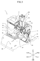
- a cloth bonding device 1 that is shown in FIG. 1 bonds an upper cloth and a lower cloth, which are disposed facing one another with an adhesive between them, by pressing them together while they are clamped between and fed by an upper roller 12 and a lower roller 18.
- the direction in which the upper cloth and the lower cloth are fed by the cloth bonding device 1 is the front-to-rear direction.
- the configuration of the cloth bonding device 1 will be explained with reference to FIGS. 1 to 9 .
- Any one of nozzles 40, 48 (refer to FIG. 6 ), and 50 (refer to FIG. 5 ) is removably mounted in the cloth bonding device 1.
- the configuration of the cloth bonding device 1 when the nozzle 40 is mounted will be explained.
- the cloth bonding device 1 is installed on the top face of a work bench 200.
- the cloth bonding device 1 includes a base portion 2, a pillar portion 3, an arm portion 4, a lever 9, the nozzle 40, an upper mounting base 21 (refer to FIG. 7 ), an upper drive mechanism 15, a lower mounting base 29, a lower drive mechanism 25, and the like.
- the base portion 2 has a substantially three-dimensional rectangular shape and is fixed to the top face of the work bench 200 by screws.
- the base portion 2 is provided with an attachment face 2A on its left side.
- the attachment face 2A is parallel to the vertical direction.
- the attachment face 2A is located on the right of an opening 201 in the work bench 200.
- the pillar portion 3 is a substantially square column that extends vertically upward from the top face of the base portion 2.
- the arm portion 4 extends to the left from the upper end of the pillar portion 3.
- the arm portion 4 extends in the left-right direction such that it faces the base portion 2.
- the arm portion 4 is provided with a removable cover 4A on its left end and is provided with a command switch on the lower part of its front face.
- the command switch accepts an operation to move the nozzle 40 to a proximate position or a retracted position, for example.
- the arm portion 4 includes a gear pump, a cartridge mounting portion 14, a lever swinging mechanism 16, and the like inside the cover 4A (refer to FIG. 1 ).
- the gear pump is provided in the left front side of the interior of the arm portion 4.
- the gear pump is provided with a supply channel for the adhesive in its interior.
- the gear pump is driven by a pump motor to draw an appropriate amount of the adhesive from the cartridge mounting portion 14 and to supply the adhesive, through a flow channel in the interior of a pivotal shaft 9A, to a supply channel 9B of the lever 9 (refer to FIG. 5 ), which will be described later.
- the pump motor is provided on the right of the gear pump and is positioned inside the arm portion 4.
- the cartridge mounting portion 14 is provided to the rear of the gear pump and includes a main body 14A and a lid 14B.
- the main body 14A covers a periphery of a storage portion 14C.
- the storage portion 14C extends in the up-down direction and is a bottomed square cylinder whose top portion is open.
- a cartridge is mounted inside the storage portion 14C such that it can be removed.
- the cartridge contains a hot melt adhesive.
- the hot melt adhesive liquefies when it is heated to a specified temperature and hardens at a temperature lower than the specified temperature.
- the storage portion 14C is provided with a pair of heaters on both sides of the cartridge. The pair of the heaters heat the cartridge. The adhesive therefore melts and liquefies.
- the lid 14B can be mounted on and removed from the top portion of the storage portion 14C and opens and closes the opening in the top portion of the storage portion 14C.
- the lever 9 is arm-shaped and extends downward from the front end of the bottom face of the arm portion 4.
- the pivotal shaft 9A supports the lever 9 such that the lever 9 can swing.
- the pivotal shaft 9A extends in the left-right direction, and its right end is connected to the gear pump.
- the lower end of the lever 9 can swing in the front-rear direction around the pivotal shaft 9A.
- the nozzle 40 can be mounted on and removed from the lower end of the lever 9, which supports the nozzle 40.
- the supply channel 9B for the adhesive (refer to FIG. 5 ) is provided in the interior of the lever 9.
- the upper end of the supply channel 9B is connected to the flow channel in the interior of the pivotal shaft 9A.
- the supply channel 9B supplies to the nozzle 40 the adhesive that the gear pump supplies through the flow channel.
- the lever 9 is provided with a bar-shaped heater in the vicinity of the supply channel. The heater heats the adhesive that flows through the supply channel 9B.
- the lever swinging mechanism 16 is provided on the left end of the arm portion 4.
- the lever swinging mechanism 16 includes an air cylinder 27 and a coupling shaft 26.
- the air cylinder 27 is adjacent to the left side of the storage portion 14C of the cartridge mounting portion 14.
- the air cylinder 27 is provided with two air inlets 27A (refer to FIG. 2 ) to the front and the rear.
- the two air inlets 27A are connected to intake-exhaust hoses.
- the cloth bonding device 1 controls the intake of compressed air from the intake-exhaust hoses to the air inlets 27A and the exhaust of air from the air inlets 27A to the intake-exhaust hoses.
- a piston in the interior of the air cylinder 27 is moved by the control of the intake and exhaust.
- the piston is connected to a movable portion 27B.
- the movable portion 27B is rod-shaped and extends downward toward the front from the piston.
- the coupling shaft 26 is provided on a tip end of the movable portion 27B and extends in the left-right direction.
- the coupling shaft 26 is rotatably coupled to the lever 9 at a position that is set apart from the pivotal shaft 9A upward and to the front.
- the nozzle 40 includes a mounting portion 41 and an extension portion 43.
- the mounting portion 41 is substantially rectangular in a plan view.
- the mounting portion 41 is provided with two insertion holes 41A near its left front edge and its right rear edge.
- the two insertion holes 41A extend through the mounting portion 41 in the up-down direction, and they are positioned opposite two of four threaded holes 9C.
- the four threaded holes 9C are provided in the bottom face of the lever 9. Screws 45 that are inserted into the two insertion holes 41 A are tightened into the two threaded holes 9C.
- the nozzle 40 is thus mounted on the bottom face of the lever 9.
- the extension portion 43 extends toward the lower rear from the mounting portion 41 and extends to the right from its lower end.
- a supply channel for the adhesive is provided in the interior of the extension portion 43.
- the supply channel of the extension portion 43 is continuous with the supply channel 9B.
- Discharge outlets are provided in the bottom face of the extension portion 43.
- the discharge outlets are arrayed in the left-right direction on the right of the supply channel 9B, and they discharge the adhesive that is supplied through the supply channel of the extension portion 43. Therefore, the nozzle 40 discharges the adhesive onto the lower cloth on the right of the supply channel 9B.
- the width of the adhesive discharged from the nozzle 40 may be 10 millimeters, for example.
- the discharge width is the left-right width of the adhesive that is discharged onto the lower cloth.
- the nozzle 40 can be replaced with one of a nozzle 50 and a nozzle 48.
- the nozzle 50 differs from the nozzle 40 in that the adhesive is discharged on the left of the supply channel 9B.
- the operator replaces the nozzle 40 with the nozzle 50 in accordance with the bonding process of the cloth bonding device 1.
- the nozzle 50 includes a mounting portion 51 and an extension portion 53.
- the mounting portion 51 is substantially rectangular in a plan view.
- the mounting portion 51 is provided with insertion holes 51A near its right front edge and its left rear edge.
- the two insertion holes 51A extend through the mounting portion 51 in the up-down direction, and they are positioned opposite two of the four threaded holes 9C.
- the two threaded holes 9C that are opposite to the two insertion holes 51A are different from the two threaded holes 9C that are opposite to the two insertion holes 41 A of the mounting portion 41 of the nozzle 40.
- the inside diameters of the insertion holes 51A are the same as the inside diameters of the insertion holes 41 A.
- Each of two screws 45 is inserted into corresponding one of the two insertion holes 51 A and is tightened into corresponding one of the two threaded holes 9C.
- the extension portion 53 extends toward the lower rear from the mounting portion 51 and extends to the left from its lower end.
- a supply channel and discharge outlets are provided in the extension portion 53 in the same manner as in the extension portion 43.
- the width of the adhesive discharged from the nozzle 50 may be 10 millimeters, for example.
- the nozzle 48 includes an extension portion 48A instead of the extension portion 43, but is otherwise configured in the same manner as the nozzle 40.
- the extension portion 48A extends toward the lower rear from the mounting portion 41 and extends to the right from its lower end.
- the nozzle 48 discharges the adhesive on the right of the supply channel 9B (refer to FIG. 5 ).
- the width of the adhesive discharged from the nozzle 48 may be 8 millimeters, for example, which is a shorter discharge width than that of the nozzle 40.
- the operator replaces the nozzle 40 with the nozzle 48 in accordance with the bonding process of the cloth bonding device 1.
- the configurations of the upper mounting base 21 and the upper drive mechanism 15 will be explained with reference to FIGS. 7 and 8 .
- the cartridge mounting portion 14 (refer to FIG. 2 ) is not shown in FIG. 7 .
- the upper mounting base 21 is provided in the rear part of the interior of the arm portion 4.
- the upper mounting base 21 is substantially rectangular in a rear view and is provided with a pair of rails 67, first fastening holes 65, and second fastening holes 66.
- the pair of the rails 67 are provided on the rear face of the upper mounting base 21 and extend to the left and the right.
- the pair of the rails 67 are arranged facing each other with an interval in the up-down direction.
- the first fastening holes 65 are disposed above the pair of the rails 67 and discretely arrayed in the left-right direction.
- the second fastening holes 66 are provided in the lower rail 67 of the pair of the rails 67.
- the second fastening holes 66 are discretely arrayed in the left-right direction.
- the upper drive mechanism 15 is fixed to the upper mounting base 21.
- the upper drive mechanism 15 supports and rotationally drives the upper roller 12.
- the upper drive mechanism 15 includes an upper base 72, an upper motor 76, an upper arm base 75, an upper arm 74, and an upper driving force transmission portion 78.
- the upper base 72 is substantially rectangular in a rear view and faces the upper mounting base 21.
- the upper base 72 is provided with a carrier portion, a second through-hole 72B, and two first through-holes 72A.
- the carrier portion is provided on the upper edge of the front face of the upper base 72 and projects toward the front. By engaging with the upper rail 67 of the pair of the rails 67, the carrier portion carries the upper base 72 on the top face of the upper rail 67.
- the second through-hole 72B and the two first through-holes 72A are oblong holes whose long axes extend in the left-right direction, and they extend through the upper base 72 in the front-rear direction.
- the two first through-holes 72A are provided in the upper part of the upper base 72, with a interval separating them in the left-right direction.
- Each one of the two first through-holes 72A is opposite at least one of the first fastening holes 65.
- the second through-hole 72B is provided below the two first through-holes 72A.
- the second through-hole 72B is opposite at least one of the second fastening holes 66.
- the short axes of the first through-holes 72A and the second through-hole 72B are slightly longer than the diameters of the first fastening holes 65 and the second fastening holes 66.
- a second fastening member 85 and two first fastening members 81 may be screws, for example.
- Each of the two first fastening members 81 is inserted through a washer 81A and through corresponding one of the two first through-holes 72A, then tightened into corresponding one of the first fastening holes 65.
- the second fastening member 85 is inserted through a washer 85A and through the second through-hole 72B, then tightened into one of the second fastening holes 66.
- the upper drive mechanism 15 is thus fixed to the upper mounting base 21.
- the upper arm base 75 has an L-shaped box shape in a left side view, extending downward from the lower edge of the upper base 72 then bending toward the front.
- the upper arm base 75 is formed as a single unit with the upper base 72.
- a front end portion 75A on the lower end of the upper arm base 75 is coupled to the upper arm 74 such that the upper arm 74 can rotate.
- the upper arm 74 extends toward the front from the point where it is coupled to the front end portion 75A of the upper arm base 75, and its front end bends and extends downward toward the front.
- the front end of the upper arm 74 supports the upper roller 12 such that the upper roller 12 can rotate.
- the upper roller 12 is disposed downstream from the nozzle 40 in the feed direction and above the work bench 200.
- the upper motor 76 is fixed to the rear face of the upper base 72.
- the upper motor 76 is provided with a drive shaft 76A.
- the rear end of the upper arm 74 is coupled to a movable portion of an air cylinder 77 such that the upper arm 74 can rotate.
- the air cylinder 77 is disposed inside the upper arm base 75 and is provided with an air inlet.
- An intake-exhaust hose is connected to the air inlet.
- the cloth bonding device 1 controls the intake of compressed air from the intake-exhaust hose to the air inlet and the exhaust of air from the air inlet to the intake-exhaust hose.
- a piston in the interior of the air cylinder 77 is moved by the control of the intake and exhaust.
- the lower end of the piston is connected to the rear end of the upper arm 74. When the piston moves, the upper arm 74 swings around the point where it is coupled to the front end portion 75A of the upper arm base 75.
- the upper driving force transmission portion 78 includes a drive pulley 23, a first follower pulley, a first synchronization belt 24, a second follower pulley, a second synchronization belt, third follower pulley, and the like.
- the drive pulley 23 is fixed to the drive shaft 76A of the upper motor 76.
- the first synchronization belt 24 and the first follower pulley are provided in the interior of the upper arm base 75.
- the second follower pulley, the second synchronization belt, and the third follower pulley are provided in the interior of the upper arm 74.
- the first synchronization belt 24 spans the interval between the drive pulley 23 and the first follower pulley.
- the first follower pulley is provided on the front end portion 75A of the upper arm base 75.
- the second follower pulley is provided on the rotating shaft of the first follower pulley, in the interior of the upper arm 74.
- the third follower pulley is fixed to the rotating shaft of the upper roller 12.
- the second synchronization belt spans the interval between the second follower pulley and the third follower pulley.
- the driving force of the upper motor 76 is thus transmitted to the upper roller 12 through the drive pulley 23, the first synchronization belt 24, the first follower pulley, the second follower pulley, the second synchronization belt, and the third follower pulley, such that the upper roller 12 rotates clockwise in a left side view.
- the upper base 72 can be moved to the left and the right in a state in which the carrier portion is carried by the upper rail 67.
- the range of movement of the upper drive mechanism 15 is the range of movement of the upper base 72, which is the range in which the first through-holes 72A are opposite the first fastening holes 65 into which the first fastening members 81 have been tightened and in which the second through-hole 72B is opposite the second fastening hole 66 into which the second fastening member 85 has been tightened.
- the upper drive mechanism 15 is positioned in a first position (the same as in FIG. 6 ).
- the first position is the position of the upper drive mechanism 15 in the left-right direction where the center of the upper roller 12 in the left-right direction is substantially aligned with the center of the discharge width of the nozzle 40 in the left-right direction.
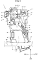
- the lower mounting base 29 is inserted from above into the inner side of the opening 201 (refer to FIG. 1 ) of the work bench 200 and is fixed to the attachment face 2A of the base portion 2.
- the lower mounting base 29 includes a first mounting base 61 and a second mounting base 62.
- the first mounting base 61 has an upper part that is substantially rectangular in a left side view and a lower part that bends and extends downward toward the front from the upper part.
- the upper part of the first mounting base 61 is fixed to the attachment face 2A by four screws 44, for example.
- the first mounting base 61 When fixed to the attachment face 2A, the first mounting base 61 extends to the underside of the work bench 200 (refer to FIG. 3 ) through the inner side of the opening 201 (refer to FIG. 1 ).
- the second mounting base 62 extends toward the left from the lower part of the first mounting base 61.
- the second mounting base 62 includes a support portion 62A and a rising portion 62B.
- the support portion 62A is a plate-shaped member that is substantially rectangular in a plan view.
- the support portion 62A supports the lower drive mechanism 25 from below.
- the rising portion 62B is a plate-shaped member that is substantially rectangular in a rear view, and it extends upward toward the rear from the rear edge of the support portion 62A.
- the upper part of the rising portion 62B is provided with two insertion holes 58.
- the two insertion holes 58 are oblong holes whose long axes extend in the left-right direction, and they extend through the rising portion 62B.
- the two insertion holes 58 are arrayed in the left-right direction with an interval between them.
- the lower drive mechanism 25 supports and rotationally drives the lower roller 18.
- the lower drive mechanism 25 includes a motor containing portion 82, a lower motor 84, a lower arm 86, and a lower driving force transmission portion 88.
- the motor containing portion 82 is box-shaped and is supported by the support portion 62A of the second mounting base 62.
- the motor containing portion 82 contains the lower motor 84 (refer to FIG. 7 ) in its interior.
- the motor containing portion 82 includes a rear wall portion 82A and a left wall portion 82B.
- the rear wall portion 82A faces the rising portion 62B.
- the left wall portion 82B extends toward the front from the left end of the rear wall portion 82A.
- the left wall portion 82B supports the lower arm 86 and the lower driving force transmission portion 88.
- the drive shaft of the lower motor 84 projects to the left of the left wall portion 82B.
- the lower arm 86 is substantially L-shaped in a right side view, and it extends upward toward the front from the left wall portion 82B, then bends at its front end and extends upward toward the rear.
- the upper end of the lower arm 86 passes through the opening 201 (refer to FIG. 2 ) and extends above the work bench 200.
- the lower arm 86 supports the lower roller 18 such that the lower roller 18 can rotate.
- the lower roller 18 is disposed downstream from the nozzle 40 in the feed direction and faces the upper roller 12.
- the lower driving force transmission portion 88 is provided in the interior of the lower arm 86, and it transmits the driving force of the lower motor 84 to the lower roller 18.
- the lower driving force transmission portion 88 includes a drive pulley, a follower pulley 88A, a synchronization belt 88B, and the like.
- the drive pulley is fixed to the drive shaft of the lower motor 84.
- the follower pulley 88A is fixed to the rotating shaft of the lower roller 18.
- the synchronization belt 88B travels in conjunction with the rotation of the drive pulley and rotates the follower pulley 88A.
- the driving force of the lower motor 84 is transmitted to the lower roller 18 through the drive pulley, the synchronization belt 88B, and the follower pulley 88A, and the lower roller 18 rotates counterclockwise in a left side view.
- the lower roller 18 and the upper roller 12 clamp the upper cloth and the lower cloth between them.
- the lower roller 18 operates in coordination with the upper roller 12 to feed the upper cloth and the lower cloth in the feed direction.
- threaded holes 82C are provided in the rear wall portion 82A of the motor containing portion 82.
- one of the threaded holes 82C is shown (the same as in FIG. 11 ).
- the threaded holes 82C are discretely arrayed in the left-right direction.
- Each one of the two insertion holes 58 in the rising portion 62B is opposite at least one of the threaded holes 82C.
- the short axes of the two insertion holes 58 are slightly longer than the diameters of the threaded holes 82C.
- Each one of two threaded members 59 is passed through one of the two insertion holes 58 and tightened into one of the threaded holes 82C.
- the lower drive mechanism 25 is thus fixed to the lower mounting base 29.
- the motor containing portion 82 can be moved to the left and the right in a state in which it is supported by the support portion 62A.
- the lower drive mechanism 25 can be moved to the left and the right.
- the range of movement of the lower drive mechanism 25 is the range of movement of the motor containing portion 82.
- the range of movement of the motor containing portion 82 is the range in which two of the threaded holes 82C are opposite the two insertion holes 58. In FIG.
- the lower drive mechanism 25 is positioned in a first specified position (the same as in FIG. 6 ).
- the first specified position is the position of the lower drive mechanism 25 in the left-right direction where the center of the lower roller 18 in the left-right direction is substantially aligned with the center of the discharge width of the nozzle 40 in the left-right direction.
- the method for replacing the nozzle 40 of the cloth bonding device 1 with the nozzle 50 will be explained with reference to FIGS. 5 and 8 to 12 .
- the operator operates the command switch to swing the lever 9 and move the nozzle 40 from the proximate position (refer to FIG. 3 ) to the retracted position (refer to FIG. 4 ).
- the operator loosens and removes the two screws 45, then removes the nozzle 40 from the lever 9.
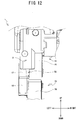
- the operator mounts the nozzle 50 onto the lever 9 using the two screws 45 (refer to FIG. 12 ).
- the operator operates the command switch to swing the lever 9 and move the nozzle 50 from the retracted position to the proximate position.
- the direction in which the extension portion 53 of the nozzle 50 extends is different from the direction in which the extension portion 43 of the nozzle 40 extends.
- the position in the left-right direction of the discharge outlets that discharge the adhesive is different from the position of the discharge outlets of the nozzle 40.
- the adhesive discharge outlets of the nozzle 50 are positioned to the left of the adhesive discharge outlets of the nozzle 40.
- the operator loosens the two tightened first fastening members 81 to the extent that they do not fall out of the corresponding first fastening holes 65.
- the operator loosens the tightened second fastening member 85 to the extent that it does not fall out of the second fastening hole 66.
- the first through-holes 72A and the second through-hole 72B are each oblong holes whose long axes extend in the left-right direction, so the upper base 72 is able to move to the left in a state in which it is carried on the pair of the rails 67.
- the operator moves the upper drive mechanism 15 to the left along the pair of the rails 67 from the first position (refer to FIGS.
- the second position is the position of the upper drive mechanism 15 in the left-right direction where the center of the upper roller 12 in the left-right direction is substantially aligned with the center of the discharge width of the nozzle 50 in the left-right direction.
- the two first fastening members 81 may be tightened into different ones of the first fastening holes 65 from the ones into which they were tightened previously.
- the second fastening member 85 may be tightened into a different one of the second fastening holes 66 from the one into which it was tightened previously.
- the operator When the operator has moved the upper drive mechanism 15 to the second position, it is necessary for the position of the lower drive mechanism 25 to be changed such that the lower roller 18 will be disposed opposite the upper roller 12. As shown in FIGS. 9 , 11 , and 12 , the operator loosens and removes the two threaded members 59.
- the operator moves the lower drive mechanism 25 to the left from the first specified position (refer to FIGS. 6 , 9 ) to a second specified position (refer to FIGS. 11 , 12 ).
- the second specified position is the position of the lower drive mechanism 25 in the left-right direction where the center of the lower roller 18 in the left-right direction is substantially aligned with the center of the discharge width of the nozzle 50 in the left-right direction.
- the operator inserts each of the two threaded members 59 through corresponding one of the two insertion holes 58 and tightens it into corresponding one of the two threaded holes 82C.
- the lower drive mechanism 25 is fixed to the lower mounting base 29 in the second specified position.
- the positions of the threaded holes 82C into which the threaded members 59 are tightened when the lower drive mechanism 25 is in the second specified position are different from their positions when the lower drive mechanism 25 is in the first specified position.
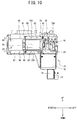
- the method for replacing the nozzle 40 of the cloth bonding device 1 with the nozzle 48 will be explained with reference to FIGS. 6 , 9 , and 10 .
- the explanation will be simplified where the work is the same as for replacing the nozzle 40 with the nozzle 50.
- the operator swings the lever 9 and moves the nozzle 40 from the proximate position to the retracted position, then removes the nozzle 40 (refer to FIG. 6 ) from the lever 9.
- the operator fixes the nozzle 48 (refer to FIG. 6 ) to the lever 9.
- the operator swings the lever 9 and moves the nozzle 48 from the retracted position to the proximate position.
- the nozzle 48 has a different adhesive discharge width from that of the nozzle 40.
- the center of its discharge width in the left-right direction is in a different position from that of the nozzle 40.
- the position of the center of the discharge width of the nozzle 48 in the left-right direction is to the left of the position of the center of the discharge width of the nozzle 40 in the left-right direction.
- the operator loosens the two tightened first fastening members 81 and the tightened second fastening member 85 to the extent that they do not fall out of the corresponding first fastening holes 65 and the corresponding second fastening hole 66.
- the operator moves the upper drive mechanism 15 to the left along the pair of the rails 67 from the first position to a third position (refer to FIG. 8 ).
- the third position is the position of the upper drive mechanism 15 in the left-right direction where the center of the upper roller 12 in the left-right direction is substantially aligned with the center of the discharge width of the nozzle 48 in the left-right direction.
- the third position is situated between the first position and the second position (refer to FIG. 10 ).
- the first fastening holes 65 into which the operator tightens the first fastening members 81 when the upper drive mechanism 15 is in the third position are different from those into which the operator tightens the first fastening members 81 when the upper drive mechanism 15 is in the first position.
- the second fastening hole 66 into which the operator tightens the second fastening member 85 when the upper drive mechanism 15 is in the third position is different from that into which the operator tightens the second fastening member 85 when the upper drive mechanism 15 is in the first position.
- the operator When the operator has moved the upper drive mechanism 15 to the third position, it is necessary for the position of the lower drive mechanism 25 to be changed such that the lower roller 18 will be disposed opposite the upper roller 12. As shown in FIG. 9 , the operator loosens and removes the two threaded members 59, then moves the lower drive mechanism 25 to the left from the first specified position (refer to FIG. 9 ) to a third specified position.
- the third specified position is the position of the lower drive mechanism 25 in the left-right direction where the center of the lower roller 18 in the left-right direction is substantially aligned with the center of the discharge width of the nozzle 48 in the left-right direction.
- the third specified position is situated between the first specified position and the second specified position (refer to FIG. 11 ).
- the operator inserts each of the two threaded members 59 through corresponding one of the two insertion holes 58 and tightens it into corresponding one of the two threaded holes 82C.
- the lower drive mechanism 25 is fixed to the lower mounting base 29 in the third specified position.
- the method for removing the upper drive mechanism 15 and the lower drive mechanism 25 will be explained with reference to FIG. 7 .
- the operator removes the upper base 72 from the upper mounting base 21 by removing the first fastening members 81 and the second fastening member 85. That makes it possible for the operator to remove the upper drive mechanism 15 from the upper mounting base 21.
- the operator can remove the motor containing portion 82 from the lower mounting base 29 by removing the two threaded members 59 (refer to FIG. 9 ). That makes it possible for the operator to remove the lower drive mechanism 25 from the lower mounting base 29.
- the operator can adjust the position in the left-right direction at which the upper drive mechanism 15 is fixed to the upper mounting base 21. Therefore, when mounting the nozzle 50 on the lever 9 instead of the nozzle 40, the operator is able to move the upper drive mechanism 15 such that the center of the upper roller 12 in the left-right direction is substantially aligned with the center of the discharge width of the nozzle 50 in the left-right direction. It is not necessary to replace the lever 9 with another lever that is compatible with the nozzle 50. The cloth bonding device 1 is thus able to simplify the task of replacing the nozzle 40 with the nozzle 50 in accordance with the bonding process.
- the cloth bonding device 1 does not need to be provided with a lever that is compatible with the nozzle 50, its cost can be lowered. Because the task of replacing the nozzle 40 with the nozzle 50 is simplified, the time that the operator spends doing maintenance work on the cloth bonding device 1 is reduced.
- the operator When switching from the nozzle 40 to the nozzle 50, the operator can easily align the center of the upper roller 12 in the left-right direction with the center of the discharge width of the nozzle 50 in the left-right direction. Therefore, between them, the upper roller 12 and the lower roller 18 are able to clamp the upper cloth and the lower cloth, to which the adhesive is adhering, without any deviation to the left or the right.
- the cloth bonding device 1 is able to achieve stable feeding of the upper cloth and the lower cloth. The cloth bonding device 1 can therefore easily discharge the adhesive onto the ideal area on the lower cloth, even when the operator replaces the nozzle 40 with the nozzle 50, which discharges the adhesive in a different position in relation to the supply channel 9B from where the nozzle 40 discharges the adhesive.
- Each one of the pair of the rails 67 guides the upper drive mechanism 15 in the left-right direction. Therefore, the operator can easily move the upper drive mechanism 15 to the left and the right.
- the operator tightens the first fastening member 81 that has been inserted through the first through-hole 72A into one of the first fastening holes 65.
- the operator tightens the second fastening member 85 that has been inserted through the second through-hole 72B into one of the second fastening holes 66. Therefore, the upper drive mechanism 15 can be fixed to the upper mounting base 21 at specific positions in the left-right direction.
- the first fastening holes 65, the two first through-holes 72A, the second through-hole 72B, the two first fastening members 81, and the second fastening member 85 function as a first fixing portion that fixes the upper drive mechanism 15 at one of fixing positions that are lined up in the left-right direction. Therefore, the fixing positions of the upper drive mechanism 15 are stable.
- the cloth bonding device 1 can therefore easily move the upper drive mechanism 15 to the left and the right and can stabilize the fixing positions of the upper drive mechanism 15 in relation to the upper mounting base 21.
- the operator is able to fix the upper drive mechanism 15 to the upper mounting base 21 by inserting the first fastening members 81 through the first through-holes 72A and tightening them into the first fastening holes 65 and by inserting the second fastening member 85 through the second through-hole 72B and tightening it into the second fastening hole 66. Therefore, the cloth bonding device 1 is able to fix the upper drive mechanism 15 securely to the upper mounting base 21.
- the second through-hole 72B and the two first through-holes 72A are oblong holes whose long axes extend in the left-right direction.
- each one of the two first through-holes 72A is easily positioned opposite one of the first fastening holes 65, and the second through-hole 72B is easily positioned opposite one of the second fastening holes 66. Therefore, the cloth bonding device 1 can improve the operability of the fixing of the upper drive mechanism 15 to the upper mounting base 21.
- the second fastening holes 66 are lined up in the left-right direction below the first fastening holes 65.
- the second fastening member 85 is tightened into one of the second fastening holes 66 below the two first fastening members 81.
- the first fastening members 81 and the second fastening member 85 fix the upper drive mechanism 15 to the upper mounting base 21 in positions that are apart from one another in the up-down direction. Therefore, the cloth bonding device 1 is able to fix the upper drive mechanism 15 even more securely to the upper mounting base 21.
- the upper drive mechanism 15 is able to move to the left and the right along the pair of the rails 67. Because the pair of the rails 67, which extend in the left-right direction, are disposed such that they face one another across a interval in the up-down direction, the operator can easily move the upper drive mechanism 15 to the left and the right. Therefore, the cloth bonding device 1 can improve the operability of the moving of the upper drive mechanism 15 to the left and the right.
- the operator can remove the upper drive mechanism 15 from the upper mounting base 21 by removing the second fastening member 85 and the two first fastening members 81.
- the removed upper drive mechanism 15 can be placed on the work bench 200 in a position that is set apart from the base portion 2, for example. Because it is possible to remove only the upper drive mechanism 15, the operator can easily performs tensions adjustments and the like on the first synchronization belt 24 and the second synchronization belt, for example. Therefore, the cloth bonding device 1 can simplify maintenance work on the upper drive mechanism 15.
- the lever 9 supports the nozzle 40 and the nozzle 48, which have different adhesive discharge widths, such that either one can be mounted and removed.
- the operator When replacing the nozzle 40 with the nozzle 48, the operator is able to align the center of the upper roller 12 in the left-right direction with the center of the discharge width of the nozzle 48 in the left-right direction. Between them, the upper roller 12 and the lower roller 18 are able to clamp the upper cloth and the lower cloth, to which the adhesive is adhering, without any deviation to the left or the right.
- the cloth bonding device 1 is able to achieve stable feeding of the upper cloth and the lower cloth. The cloth bonding device 1 can therefore easily discharge the adhesive onto the ideal area on the lower cloth, even when the operator replaces the nozzle 40 with the nozzle 48, for which the adhesive discharge width is different from that of the nozzle 40.
- the second specified position is the position of the lower drive mechanism 25 in the left-right direction where the center of the lower roller 18 in the left-right direction is substantially aligned with the center of the discharge width of the nozzle 50 in the left-right direction.
- the lower roller 18 and the upper roller 12 are able to clamp the upper cloth and the lower cloth, to which the adhesive is adhering, without any deviation to the left or the right.
- the cloth bonding device 1 is able to achieve stable feeding of the upper cloth and the lower cloth. The cloth bonding device 1 can therefore discharge the adhesive onto the ideal area on the lower cloth even more easily, even when the operator replaces the nozzle 40 with the nozzle 50, which projects from the supply channel 9B in a different direction than does the nozzle 40.
- the threaded holes 82C, the two insertion holes 58, and the two threaded members 59 function as a second fixing portion that fixes the lower drive mechanism 25 at one of fixing positions that are lined up in the left-right direction. Therefore, the cloth bonding device 1 can stabilize the fixing positions of the lower drive mechanism 25.
- the two insertion holes 58 are oblong holes whose long axes extend in the left-right direction.
- each one of the two insertion holes 58 is easily positioned opposite one of the threaded holes 82C. Therefore, the cloth bonding device 1 can improve the operability of the fixing of the lower drive mechanism 25 to the lower mounting base 29.
- the operator can remove the lower drive mechanism 25 from the lower mounting base 29 by removing the two threaded members 59.
- the removed lower drive mechanism 25 can be placed on the work bench 200 in a position that is set apart from the base portion 2, for example. Because it is possible to remove only the lower drive mechanism 25, the operator can easily performs tensions adjustments and the like on the synchronization belt 88B, for example. Therefore, the cloth bonding device 1 can simplify maintenance work on the lower drive mechanism 25.
- the present invention is not limited to the embodiment that is described above, and various types of modifications can be made.
- the cloth bonding device 1 may be provided with one rail 67.
- the cloth bonding device 1 may be provided with one first through-hole 72A.
- the cloth bonding device 1 may also fix the upper drive mechanism 15 to the upper mounting base 21 using three bolts and three nuts, for example, instead of the second fastening member 85 and the two first fastening members 81. In the same manner, the cloth bonding device 1 may also fix the lower drive mechanism 25 to the lower mounting base 29 using two bolts and two nuts, for example, instead of the two threaded members 59.
- the cloth bonding device 1 may be provided with round holes that are discretely disposed in the left-right direction.
- the upper drive mechanism 15 moves in the left-right direction, one of the round holes would be positioned opposite one of the first fastening holes 65.
- the operator would tighten the first fastening members 81 that have been inserted through the round holes into the first fastening holes 65.
- the operator could fix the upper drive mechanism 15 to the upper mounting base 21 at one of the fixing positions in the left-right direction.
- the cloth bonding device 1 instead of being provided with the two insertion holes 58, may be provided with round holes that are discretely disposed in the left-right direction.
- the upper base 72 may be provided with fastening holes instead of with the two first through-holes 72A.
- the first fastening holes 65 and the second fastening holes 66 would not be provided in the upper mounting base 21, and the carrier portion that is provided on the upper edge of the front face of the upper base 72 would need only to bend downward on the front face side of the upper mounting base 21.
- the operator would tighten the first fastening members 81 into the fastening holes in the upper base 72.
- the front ends of the first fastening members 81 would clamp the upper mounting base 21 against the carrier portion on the front face side of the upper mounting base 21. Therefore, the upper drive mechanism 15 could be fixed to the upper mounting base 21.
- the upper drive mechanism 15 is fixed to the upper mounting base 21 using the second fastening member 85 and the two first fastening members 81, but a lever may also be provided on the upper base 72, and the upper drive mechanism 15 may be fixed by rotating the lever.
- the upper drive mechanism 15 may also include a drive source such as a motor, a cylinder, or the like that moves the upper drive mechanism 15 to the left and the right, with the carrier portion of the upper base 72 being carried by the upper rail 67.
- a ball screw that extends in the left-right direction may be coupled to the upper base 72, and the upper drive mechanism 15 may move the upper base 72 to the left and the right by rotating the ball screw.
- a rack that extends in the left-right direction may be coupled to the upper base 72, and a pinion that meshes with the rack may be provided on the upper mounting base 21.
- the upper drive mechanism 15 may then move the upper base 72 to the left and the right by rotating the pinion.
- a motor may also be provided as the drive source for rotating the ball screw or the pinion.
- the lower arm 86 is substantially L-shaped in a right side view, and it extends upward toward the front from the left wall portion 82B, then bends at its front end and extends upward toward the rear. However, the lower arm 86 may also extend straight upward from its lower end, and it may also extend horizontally.
- the adhesive discharge widths of the nozzles 40, 48, and 50 are not limited to the values in the embodiment that is described above.
- the adhesive discharge width of the nozzle 48 may also be greater than the adhesive discharge widths of the nozzles 40 and 50.
- the nozzle 50 may be provided with an extension portion whose width is the same as the adhesive discharge width of the nozzle 48.
- the lower drive mechanism 25 is able to move within the range where two of the threaded holes 82C can be positioned opposite the two insertion holes 58.
- the lower drive mechanism 25 is fixed to the lower mounting base 29 by inserting each one of the two threaded members 59 through one of the two insertion holes 58 and tightening it into the corresponding one of the threaded holes 82C.
- the present invention is not limited to this configuration, and the lower drive mechanism 25 may also be permanently fixed to the lower mounting base 29 and unable to move in the left-right direction.
- the lower roller and the upper roller 12 would be able to clamp the upper cloth and the lower cloth and feed them in the feed direction, even if the upper drive mechanism 15 moves to the left or the right.
- the upper drive mechanism 15 could also be permanently fixed to the upper mounting base 21 and unable to move in the left-right direction. In those cases, it would be acceptable for the length of the upper roller to be made longer than the length of the upper roller 12 in the embodiment that is described above, and for the lower drive mechanism 25 to be moved in the left-right direction.
- the upper drive mechanism 15 it is preferable for the upper drive mechanism 15 to be able to move in the left-right direction.
Landscapes
- Engineering & Computer Science (AREA)
- Mechanical Engineering (AREA)
- Textile Engineering (AREA)
- Treatment Of Fiber Materials (AREA)
- Adhesives Or Adhesive Processes (AREA)
Abstract
Description
- The present invention relates to a cloth bonding device.
- A cloth bonding device discharges an adhesive from a nozzle and the adhesive sticks to a lower cloth. With the adhesive sticking to the lower cloth, the cloth bonding device clamps an upper cloth and the lower cloth between an upper feed roller and a lower feed roller, then presses and feeds the upper cloth and the lower cloth to bond them together. A bonding process of the cloth bonding device varies according to the positions in which the upper cloth and the lower cloth are placed. The nozzle of the cloth bonding device can be replaced to fit the bonding process. A cloth bonding device that is described in Japanese Laid-Open Patent Publication No.
2010-270416 - In the cloth bonding device that is described above, the positions of the upper feed roller and the lower feed roller do not change in relation to the direction in which the nozzle extends. It is necessary for the position of the nozzle to remain the same in relation to the upper feed roller and the lower feed roller, no matter which one of nozzles that project in different directions from the support portion is mounted in the cloth bonding device. Therefore, the support portion includes a first support portion and a second support portion and supports the nozzle such that the position of the nozzle remains the same in relation to the upper feed roller and the lower feed roller, no matter which one of the nozzles that project in different directions from the support portion is mounted. When replacing nozzle, an operator must replace one of the first support portion and the second support portion with the other. Therefore, the nozzle replacement operation is sometimes burdensome.
- Various embodiments of the broad principles derived herein provide a cloth bonding device that simplifies the nozzle replacement operation.
- The cloth bonding device includes a base portion, a pillar portion, an arm portion, an upper roller, a lower roller, a nozzle, an upper drive mechanism, an upper mounting base, a guide portion, and a first fixing portion. The pillar portion extends upward from the base portion. The arm portion extends from the pillar portion and is disposed opposite the base portion. The upper roller feeds a cloth. The lower roller faces the upper roller and is disposed below the cloth. The lower roller clamps the cloth against the upper roller and feeds the cloth in a feed direction by operating in coordination with the upper roller. The nozzle can be mounted on and removed from a support body that is provided on the arm portion. The nozzle discharges an adhesive onto the cloth on upstream of the lower roller and the upper roller in the feed direction. The upper drive mechanism supports the upper roller and rotationally drives the upper roller. The upper mounting base is provided on the arm portion, and the upper drive mechanism is fixed to the upper mounting base. The guide portion is provided on the upper mounting base and extends in a specified direction. The guide portion guides the upper drive mechanism in the specified direction. The specified direction is parallel to the direction in which the arm portion extends. The first fixing portion fixes the upper drive mechanism, which is guided by the guide portion, in one of fixing positions that are lined up in the specified direction. Because an operator is able to fix the upper drive mechanism to the upper mounting base in any one of the fixing positions, it is not necessary to replace the support body when the nozzle is replaced in accordance with the bonding process of the cloth bonding device. Therefore, the cloth bonding device is able to simplify the operation of replacing the nozzle in accordance with the bonding process. The upper drive mechanism moves easily in the specified direction along the guide portion. Therefore, the cloth bonding device easily moves the upper drive mechanism in the specified direction and can stabilize the fixing position of the upper drive mechanism in relation to the upper mounting base.
- The first fixing portion may include a through-hole, a fastening member, and fastening holes. The fastening holes are provided in the upper mounting base and discretely disposed along the specified direction. The through-hole is provided in the upper drive mechanism and disposed opposite at least one of the fastening holes. The fastening member is inserted through the through-hole and tightened into one of the fastening holes. The operator inserts the fastening member through the through-hole and tightens it into the one of the fastening holes. Therefore, the cloth bonding device is able to fix the upper drive mechanism securely to the upper mounting base.
- The through-hole may also be an oblong hole having a long axis extending in the specified direction. The through-hole is easily disposed opposite one of the fastening holes. Therefore, the cloth bonding device can improve the operability of the fixing of the upper drive mechanism to the upper mounting base.
- The fastening holes may also include first fastening holes and second fastening holes. The first fastening holes are discretely disposed in the specified direction. The second fastening holes are discretely disposed in the specified direction below the first fastening holes. The through-hole may also include a first through-hole and a second through-hole. The first through-hole is disposed opposite at least one of the first fastening holes. The second through-hole is disposed opposite at least one of the second fastening holes when the first through-hole is disposed opposite the at least one of the first fastening holes. The fastening member includes a first fastening member and a second fastening member. The first fastening member is inserted through the first through-hole and tightened into one of the first fastening holes. The second fastening member is inserted through the second through-hole and tightened into one of the second fastening holes. The operator uses the first fastening member and the second fastening member, which is disposed below the first fastening member, to fix the upper drive mechanism to the upper mounting base. Therefore, the cloth bonding device is able to fix the upper drive mechanism even more securely to the upper mounting base.
- The guide portion may also include a pair of rails. The pair of the rails are arranged facing each other with an interval in the up-down direction and extend in the specified direction. Each one of the pair of the rails guides the upper drive mechanism in the specified direction. Therefore, the cloth bonding device can improve the operability of the moving of the upper drive mechanism in the specified direction.
- The upper drive mechanism may also include an upper base, an upper motor, an upper arm base, an upper arm, and an upper driving force transmission portion. The upper base is fixed to the upper mounting base. The upper base is provided with the through-hole. The upper motor is provided on the upper base. The upper arm base extends downward from the upper base. The upper arm has one end coupled to the upper arm base and another end supporting the upper roller. The upper driving force transmission portion is provided in the upper arm base and the upper arm and transmits the driving force of the upper motor to the upper roller. The operator can remove the upper drive mechanism by removing the upper base from the upper mounting base after the fastening member has been removed. Therefore, the cloth bonding device can simplify maintenance work on the upper drive mechanism.
- The nozzle may also include a first nozzle and a second nozzle. The second nozzle has a different discharge width from that of the first nozzle, the discharge width being the width, in the specified direction, of the adhesive discharged from the nozzle. In this case, the support body may support one of the first nozzle and the second nozzle in attachable and detachable manner. When replacing one of the first nozzle and the second nozzle with the other nozzle, the operator is able to align the center of the discharge width of the nozzle with the center of the upper roller in the specified direction. Therefore, the cloth bonding device can easily discharge the adhesive onto the ideal area on the cloth.
- The cloth bonding device may also include a lower drive mechanism, a lower mounting base, and a second fixing portion. The lower drive mechanism supports the lower roller and rotationally drives the lower roller. The lower mounting base is fixed to the base portion. The lower drive mechanism is fixed to the lower mounting base. The second fixing portion fixes the lower drive mechanism in one of fixing positions that are lined up in the specified direction. The second fixing portion may include an insertion hole, a threaded member, and threaded holes. The threaded holes are provided in the lower drive mechanism and discretely disposed in the specified direction. The insertion hole is provided in the lower mounting base and disposed opposite at least one of the threaded holes. The threaded member is inserted through the insertion hole and tightened into one of the threaded holes. The lower drive mechanism can be fixed to the lower mounting base in one of the fixing positions. The operator is able to align the center of the discharge width of the nozzle with the center of the lower roller in the specified direction. Therefore, the cloth bonding device can discharge the adhesive onto the ideal area on the cloth even more easily.
- The insertion hole may also be an oblong hole having a long axis extending in the specified direction. The insertion hole is easily disposed opposite at least one of the threaded holes. Therefore, the cloth bonding device can improve the operability of the fixing of the lower drive mechanism to the lower mounting base.
- The lower drive mechanism may also include a lower base, a lower motor, a lower arm, and a lower driving force transmission portion. The lower base is fixed to the lower mounting base. The lower base is provided with the threaded holes. The lower motor is provided on the lower base. The lower arm extends upward from the lower base. An upper end of the lower arm supports the lower roller. The lower driving force transmission portion is provided in the lower base and the lower arm and transmits the driving force of the lower motor to the lower roller. The operator can remove the lower drive mechanism by removing the lower base from the lower mounting base after the threaded member has been removed. Therefore, the cloth bonding device can simplify maintenance work on the lower drive mechanism.
- Embodiments will be described below in detail with reference to the accompanying drawings in which:
-
FIG. 1 is an oblique view of acloth bonding device 1; -
FIG. 2 is an oblique view of thecloth bonding device 1 that shows the interior of anarm portion 4; -
FIG. 3 is a left side view of thecloth bonding device 1 with anozzle 40 in a proximate position; -
FIG. 4 is a left side view of thecloth bonding device 1 with thenozzle 40 in a retracted position; -
FIG. 5 is an exploded oblique view of alever 9 and thenozzle 40; -
FIG. 6 is a front view of thelever 9, on which thenozzle 40 is mounted; -
FIG. 7 is an exploded oblique view of thecloth bonding device 1; -
FIG. 8 is a rear view of anupper drive mechanism 15 in a first position; -
FIG. 9 is a rear view of alower drive mechanism 25 in a first specified position; -
FIG. 10 is a rear view of theupper drive mechanism 15 in a second position; -
FIG. 11 is a rear view of thelower drive mechanism 25 in a second specified position; and -
FIG. 12 is a front view of thelever 9, on which anozzle 50 is mounted. - The explanation that follows uses the terms up, down, left, right, front, and rear for the directions that are indicated by the arrows in the drawings. A
cloth bonding device 1 that is shown inFIG. 1 bonds an upper cloth and a lower cloth, which are disposed facing one another with an adhesive between them, by pressing them together while they are clamped between and fed by anupper roller 12 and alower roller 18. The direction in which the upper cloth and the lower cloth are fed by thecloth bonding device 1 is the front-to-rear direction. - The configuration of the
cloth bonding device 1 will be explained with reference toFIGS. 1 to 9 . Any one ofnozzles 40, 48 (refer toFIG. 6 ), and 50 (refer toFIG. 5 ) is removably mounted in thecloth bonding device 1. Hereinafter, the configuration of thecloth bonding device 1 when thenozzle 40 is mounted will be explained. - As shown in
FIG. 1 , thecloth bonding device 1 is installed on the top face of awork bench 200. Thecloth bonding device 1 includes abase portion 2, apillar portion 3, anarm portion 4, alever 9, thenozzle 40, an upper mounting base 21 (refer toFIG. 7 ), anupper drive mechanism 15, alower mounting base 29, alower drive mechanism 25, and the like. - As shown in
FIG. 2 , thebase portion 2 has a substantially three-dimensional rectangular shape and is fixed to the top face of thework bench 200 by screws. Thebase portion 2 is provided with anattachment face 2A on its left side. Theattachment face 2A is parallel to the vertical direction. Theattachment face 2A is located on the right of anopening 201 in thework bench 200. Thepillar portion 3 is a substantially square column that extends vertically upward from the top face of thebase portion 2. Thearm portion 4 extends to the left from the upper end of thepillar portion 3. Thearm portion 4 extends in the left-right direction such that it faces thebase portion 2. Thearm portion 4 is provided with aremovable cover 4A on its left end and is provided with a command switch on the lower part of its front face. The command switch accepts an operation to move thenozzle 40 to a proximate position or a retracted position, for example. - As shown in
FIGS. 2 to 4 , thearm portion 4 includes a gear pump, acartridge mounting portion 14, alever swinging mechanism 16, and the like inside thecover 4A (refer toFIG. 1 ). The gear pump is provided in the left front side of the interior of thearm portion 4. The gear pump is provided with a supply channel for the adhesive in its interior. The gear pump is driven by a pump motor to draw an appropriate amount of the adhesive from thecartridge mounting portion 14 and to supply the adhesive, through a flow channel in the interior of apivotal shaft 9A, to asupply channel 9B of the lever 9 (refer toFIG. 5 ), which will be described later. The pump motor is provided on the right of the gear pump and is positioned inside thearm portion 4. - The
cartridge mounting portion 14 is provided to the rear of the gear pump and includes amain body 14A and alid 14B. Themain body 14A covers a periphery of astorage portion 14C. Thestorage portion 14C extends in the up-down direction and is a bottomed square cylinder whose top portion is open. A cartridge is mounted inside thestorage portion 14C such that it can be removed. The cartridge contains a hot melt adhesive. When the cartridge is mounted, thestorage portion 14C is able to supply the adhesive to the gear pump. The hot melt adhesive liquefies when it is heated to a specified temperature and hardens at a temperature lower than the specified temperature. Thestorage portion 14C is provided with a pair of heaters on both sides of the cartridge. The pair of the heaters heat the cartridge. The adhesive therefore melts and liquefies. Thelid 14B can be mounted on and removed from the top portion of thestorage portion 14C and opens and closes the opening in the top portion of thestorage portion 14C. - As shown in
FIGS. 3 and4 , thelever 9 is arm-shaped and extends downward from the front end of the bottom face of thearm portion 4. Thepivotal shaft 9A supports thelever 9 such that thelever 9 can swing. Thepivotal shaft 9A extends in the left-right direction, and its right end is connected to the gear pump. The lower end of thelever 9 can swing in the front-rear direction around thepivotal shaft 9A. Thenozzle 40 can be mounted on and removed from the lower end of thelever 9, which supports thenozzle 40. - The
supply channel 9B for the adhesive (refer toFIG. 5 ) is provided in the interior of thelever 9. The upper end of thesupply channel 9B is connected to the flow channel in the interior of thepivotal shaft 9A. Thesupply channel 9B supplies to thenozzle 40 the adhesive that the gear pump supplies through the flow channel. Thelever 9 is provided with a bar-shaped heater in the vicinity of the supply channel. The heater heats the adhesive that flows through thesupply channel 9B. - The
lever swinging mechanism 16 is provided on the left end of thearm portion 4. Thelever swinging mechanism 16 includes anair cylinder 27 and acoupling shaft 26. Theair cylinder 27 is adjacent to the left side of thestorage portion 14C of thecartridge mounting portion 14. Theair cylinder 27 is provided with twoair inlets 27A (refer toFIG. 2 ) to the front and the rear. The twoair inlets 27A are connected to intake-exhaust hoses. Thecloth bonding device 1 controls the intake of compressed air from the intake-exhaust hoses to theair inlets 27A and the exhaust of air from theair inlets 27A to the intake-exhaust hoses. A piston in the interior of theair cylinder 27 is moved by the control of the intake and exhaust. The piston is connected to amovable portion 27B. Themovable portion 27B is rod-shaped and extends downward toward the front from the piston. When the piston moves, themovable portion 27B moves toward the front and the rear. Thecoupling shaft 26 is provided on a tip end of themovable portion 27B and extends in the left-right direction. Thecoupling shaft 26 is rotatably coupled to thelever 9 at a position that is set apart from thepivotal shaft 9A upward and to the front. - When the
movable portion 27B of theair cylinder 27 moves downward toward the front, thelever 9 swings around thepivotal shaft 9A, and thenozzle 40 moves to the proximate position (refer toFIG. 3 ). When themovable portion 27B of theair cylinder 27 moves upward toward the rear, thelever 9 swings around thepivotal shaft 9A, and thenozzle 40 moves to the retracted position (refer toFIG. 4 ). In the proximate position, thenozzle 40 is close to the front side of the outer circumferential face of thelower roller 18. Thecloth bonding device 1 moves thenozzle 40 to the proximate position when the operator performs the bonding operation on the upper cloth and the lower cloth. In the retracted position, thenozzle 40 is a significant distance away from the outer circumferential face of thelower roller 18 toward the front. - As shown in
FIG. 5 , thenozzle 40 includes a mountingportion 41 and anextension portion 43. The mountingportion 41 is substantially rectangular in a plan view. The mountingportion 41 is provided with twoinsertion holes 41A near its left front edge and its right rear edge. The twoinsertion holes 41A extend through the mountingportion 41 in the up-down direction, and they are positioned opposite two of four threadedholes 9C. The four threadedholes 9C are provided in the bottom face of thelever 9.Screws 45 that are inserted into the twoinsertion holes 41 A are tightened into the two threadedholes 9C. Thenozzle 40 is thus mounted on the bottom face of thelever 9. - The
extension portion 43 extends toward the lower rear from the mountingportion 41 and extends to the right from its lower end. A supply channel for the adhesive is provided in the interior of theextension portion 43. The supply channel of theextension portion 43 is continuous with thesupply channel 9B. Discharge outlets are provided in the bottom face of theextension portion 43. The discharge outlets are arrayed in the left-right direction on the right of thesupply channel 9B, and they discharge the adhesive that is supplied through the supply channel of theextension portion 43. Therefore, thenozzle 40 discharges the adhesive onto the lower cloth on the right of thesupply channel 9B. The width of the adhesive discharged from thenozzle 40 may be 10 millimeters, for example. The discharge width is the left-right width of the adhesive that is discharged onto the lower cloth. - As shown in
FIGS. 5 and6 , thenozzle 40 can be replaced with one of anozzle 50 and anozzle 48. Thenozzle 50 differs from thenozzle 40 in that the adhesive is discharged on the left of thesupply channel 9B. The operator replaces thenozzle 40 with thenozzle 50 in accordance with the bonding process of thecloth bonding device 1. - The
nozzle 50 includes a mountingportion 51 and anextension portion 53. The mountingportion 51 is substantially rectangular in a plan view. The mountingportion 51 is provided withinsertion holes 51A near its right front edge and its left rear edge. The twoinsertion holes 51A extend through the mountingportion 51 in the up-down direction, and they are positioned opposite two of the four threadedholes 9C. The two threadedholes 9C that are opposite to the twoinsertion holes 51A are different from the two threadedholes 9C that are opposite to the twoinsertion holes 41 A of the mountingportion 41 of thenozzle 40. The inside diameters of the insertion holes 51A are the same as the inside diameters of the insertion holes 41 A. Each of twoscrews 45 is inserted into corresponding one of the twoinsertion holes 51 A and is tightened into corresponding one of the two threadedholes 9C. Theextension portion 53 extends toward the lower rear from the mountingportion 51 and extends to the left from its lower end. A supply channel and discharge outlets are provided in theextension portion 53 in the same manner as in theextension portion 43. The width of the adhesive discharged from thenozzle 50 may be 10 millimeters, for example. - As shown in
FIG. 6 , thenozzle 48 includes anextension portion 48A instead of theextension portion 43, but is otherwise configured in the same manner as thenozzle 40. Theextension portion 48A extends toward the lower rear from the mountingportion 41 and extends to the right from its lower end. In the same manner as thenozzle 40, thenozzle 48 discharges the adhesive on the right of thesupply channel 9B (refer toFIG. 5 ). The width of the adhesive discharged from thenozzle 48 may be 8 millimeters, for example, which is a shorter discharge width than that of thenozzle 40. The operator replaces thenozzle 40 with thenozzle 48 in accordance with the bonding process of thecloth bonding device 1. - The configurations of the upper mounting
base 21 and theupper drive mechanism 15 will be explained with reference toFIGS. 7 and8 . The cartridge mounting portion 14 (refer toFIG. 2 ) is not shown inFIG. 7 . Theupper mounting base 21 is provided in the rear part of the interior of thearm portion 4. Theupper mounting base 21 is substantially rectangular in a rear view and is provided with a pair ofrails 67, first fastening holes 65, and second fastening holes 66. The pair of therails 67 are provided on the rear face of the upper mountingbase 21 and extend to the left and the right. The pair of therails 67 are arranged facing each other with an interval in the up-down direction. The first fastening holes 65 are disposed above the pair of therails 67 and discretely arrayed in the left-right direction. The second fastening holes 66 are provided in thelower rail 67 of the pair of therails 67. The second fastening holes 66 are discretely arrayed in the left-right direction. - The
upper drive mechanism 15 is fixed to the upper mountingbase 21. Theupper drive mechanism 15 supports and rotationally drives theupper roller 12. Theupper drive mechanism 15 includes anupper base 72, anupper motor 76, anupper arm base 75, anupper arm 74, and an upper drivingforce transmission portion 78. Theupper base 72 is substantially rectangular in a rear view and faces the upper mountingbase 21. Theupper base 72 is provided with a carrier portion, a second through-hole 72B, and two first through-holes 72A. The carrier portion is provided on the upper edge of the front face of theupper base 72 and projects toward the front. By engaging with theupper rail 67 of the pair of therails 67, the carrier portion carries theupper base 72 on the top face of theupper rail 67. - The second through-
hole 72B and the two first through-holes 72A are oblong holes whose long axes extend in the left-right direction, and they extend through theupper base 72 in the front-rear direction. The two first through-holes 72A are provided in the upper part of theupper base 72, with a interval separating them in the left-right direction. Each one of the two first through-holes 72A is opposite at least one of the first fastening holes 65. The second through-hole 72B is provided below the two first through-holes 72A. The second through-hole 72B is opposite at least one of the second fastening holes 66. The short axes of the first through-holes 72A and the second through-hole 72B are slightly longer than the diameters of the first fastening holes 65 and the second fastening holes 66. - A
second fastening member 85 and twofirst fastening members 81 may be screws, for example. Each of the twofirst fastening members 81 is inserted through awasher 81A and through corresponding one of the two first through-holes 72A, then tightened into corresponding one of the first fastening holes 65. Thesecond fastening member 85 is inserted through awasher 85A and through the second through-hole 72B, then tightened into one of the second fastening holes 66. Theupper drive mechanism 15 is thus fixed to the upper mountingbase 21. - The
upper arm base 75 has an L-shaped box shape in a left side view, extending downward from the lower edge of theupper base 72 then bending toward the front. Theupper arm base 75 is formed as a single unit with theupper base 72. Afront end portion 75A on the lower end of theupper arm base 75 is coupled to theupper arm 74 such that theupper arm 74 can rotate. Theupper arm 74 extends toward the front from the point where it is coupled to thefront end portion 75A of theupper arm base 75, and its front end bends and extends downward toward the front. The front end of theupper arm 74 supports theupper roller 12 such that theupper roller 12 can rotate. Theupper roller 12 is disposed downstream from thenozzle 40 in the feed direction and above thework bench 200. Theupper motor 76 is fixed to the rear face of theupper base 72. Theupper motor 76 is provided with adrive shaft 76A. The rear end of theupper arm 74 is coupled to a movable portion of anair cylinder 77 such that theupper arm 74 can rotate. Theair cylinder 77 is disposed inside theupper arm base 75 and is provided with an air inlet. An intake-exhaust hose is connected to the air inlet. Thecloth bonding device 1 controls the intake of compressed air from the intake-exhaust hose to the air inlet and the exhaust of air from the air inlet to the intake-exhaust hose. A piston in the interior of theair cylinder 77 is moved by the control of the intake and exhaust. The lower end of the piston is connected to the rear end of theupper arm 74. When the piston moves, theupper arm 74 swings around the point where it is coupled to thefront end portion 75A of theupper arm base 75. - The upper driving
force transmission portion 78 includes adrive pulley 23, a first follower pulley, afirst synchronization belt 24, a second follower pulley, a second synchronization belt, third follower pulley, and the like. Thedrive pulley 23 is fixed to thedrive shaft 76A of theupper motor 76. Thefirst synchronization belt 24 and the first follower pulley are provided in the interior of theupper arm base 75. The second follower pulley, the second synchronization belt, and the third follower pulley are provided in the interior of theupper arm 74. Thefirst synchronization belt 24 spans the interval between thedrive pulley 23 and the first follower pulley. The first follower pulley is provided on thefront end portion 75A of theupper arm base 75. The second follower pulley is provided on the rotating shaft of the first follower pulley, in the interior of theupper arm 74. The third follower pulley is fixed to the rotating shaft of theupper roller 12. The second synchronization belt spans the interval between the second follower pulley and the third follower pulley. The driving force of theupper motor 76 is thus transmitted to theupper roller 12 through thedrive pulley 23, thefirst synchronization belt 24, the first follower pulley, the second follower pulley, the second synchronization belt, and the third follower pulley, such that theupper roller 12 rotates clockwise in a left side view. - When the operator loosens the
second fastening member 85 and the twofirst fastening members 81, theupper base 72 can be moved to the left and the right in a state in which the carrier portion is carried by theupper rail 67. In other words, theupper drive mechanism 15 can be moved to the left and the right. The range of movement of theupper drive mechanism 15 is the range of movement of theupper base 72, which is the range in which the first through-holes 72A are opposite the first fastening holes 65 into which thefirst fastening members 81 have been tightened and in which the second through-hole 72B is opposite thesecond fastening hole 66 into which thesecond fastening member 85 has been tightened. InFIG. 8 , theupper drive mechanism 15 is positioned in a first position (the same as inFIG. 6 ). The first position is the position of theupper drive mechanism 15 in the left-right direction where the center of theupper roller 12 in the left-right direction is substantially aligned with the center of the discharge width of thenozzle 40 in the left-right direction. - The configurations of the
lower mounting base 29 and thelower drive mechanism 25 will be explained with reference toFIGS. 7 and9 . Thelower mounting base 29 is inserted from above into the inner side of the opening 201 (refer toFIG. 1 ) of thework bench 200 and is fixed to theattachment face 2A of thebase portion 2. Thelower mounting base 29 includes a first mountingbase 61 and asecond mounting base 62. Thefirst mounting base 61 has an upper part that is substantially rectangular in a left side view and a lower part that bends and extends downward toward the front from the upper part. The upper part of the first mountingbase 61 is fixed to theattachment face 2A by fourscrews 44, for example. When fixed to theattachment face 2A, the first mountingbase 61 extends to the underside of the work bench 200 (refer toFIG. 3 ) through the inner side of the opening 201 (refer toFIG. 1 ). Thesecond mounting base 62 extends toward the left from the lower part of the first mountingbase 61. Thesecond mounting base 62 includes asupport portion 62A and a risingportion 62B. Thesupport portion 62A is a plate-shaped member that is substantially rectangular in a plan view. Thesupport portion 62A supports thelower drive mechanism 25 from below. The risingportion 62B is a plate-shaped member that is substantially rectangular in a rear view, and it extends upward toward the rear from the rear edge of thesupport portion 62A. The upper part of the risingportion 62B is provided with two insertion holes 58. The twoinsertion holes 58 are oblong holes whose long axes extend in the left-right direction, and they extend through the risingportion 62B. The twoinsertion holes 58 are arrayed in the left-right direction with an interval between them. - The
lower drive mechanism 25 supports and rotationally drives thelower roller 18. Thelower drive mechanism 25 includes amotor containing portion 82, alower motor 84, alower arm 86, and a lower drivingforce transmission portion 88. Themotor containing portion 82 is box-shaped and is supported by thesupport portion 62A of the second mountingbase 62. Themotor containing portion 82 contains the lower motor 84 (refer toFIG. 7 ) in its interior. Themotor containing portion 82 includes arear wall portion 82A and aleft wall portion 82B. Therear wall portion 82A faces the risingportion 62B. Theleft wall portion 82B extends toward the front from the left end of therear wall portion 82A. Theleft wall portion 82B supports thelower arm 86 and the lower drivingforce transmission portion 88. The drive shaft of thelower motor 84 projects to the left of theleft wall portion 82B. - The
lower arm 86 is substantially L-shaped in a right side view, and it extends upward toward the front from theleft wall portion 82B, then bends at its front end and extends upward toward the rear. The upper end of thelower arm 86 passes through the opening 201 (refer toFIG. 2 ) and extends above thework bench 200. At its upper end, thelower arm 86 supports thelower roller 18 such that thelower roller 18 can rotate. Thelower roller 18 is disposed downstream from thenozzle 40 in the feed direction and faces theupper roller 12. - The lower driving
force transmission portion 88 is provided in the interior of thelower arm 86, and it transmits the driving force of thelower motor 84 to thelower roller 18. The lower drivingforce transmission portion 88 includes a drive pulley, afollower pulley 88A, asynchronization belt 88B, and the like. The drive pulley is fixed to the drive shaft of thelower motor 84. Thefollower pulley 88A is fixed to the rotating shaft of thelower roller 18. Thesynchronization belt 88B travels in conjunction with the rotation of the drive pulley and rotates thefollower pulley 88A. The driving force of thelower motor 84 is transmitted to thelower roller 18 through the drive pulley, thesynchronization belt 88B, and thefollower pulley 88A, and thelower roller 18 rotates counterclockwise in a left side view. Thelower roller 18 and theupper roller 12 clamp the upper cloth and the lower cloth between them. Thelower roller 18 operates in coordination with theupper roller 12 to feed the upper cloth and the lower cloth in the feed direction. - As shown in
FIG. 9 , threadedholes 82C are provided in therear wall portion 82A of themotor containing portion 82. InFIG. 9 , one of the threadedholes 82C is shown (the same as inFIG. 11 ). The threadedholes 82C are discretely arrayed in the left-right direction. Each one of the twoinsertion holes 58 in the risingportion 62B is opposite at least one of the threadedholes 82C. The short axes of the twoinsertion holes 58 are slightly longer than the diameters of the threadedholes 82C. - Each one of two threaded
members 59 is passed through one of the twoinsertion holes 58 and tightened into one of the threadedholes 82C. Thelower drive mechanism 25 is thus fixed to thelower mounting base 29. When the operator loosens the two threadedmembers 59, themotor containing portion 82 can be moved to the left and the right in a state in which it is supported by thesupport portion 62A. In other words, thelower drive mechanism 25 can be moved to the left and the right. The range of movement of thelower drive mechanism 25 is the range of movement of themotor containing portion 82. The range of movement of themotor containing portion 82 is the range in which two of the threadedholes 82C are opposite the two insertion holes 58. InFIG. 9 , thelower drive mechanism 25 is positioned in a first specified position (the same as inFIG. 6 ). The first specified position is the position of thelower drive mechanism 25 in the left-right direction where the center of thelower roller 18 in the left-right direction is substantially aligned with the center of the discharge width of thenozzle 40 in the left-right direction. - The method for replacing the
nozzle 40 of thecloth bonding device 1 with thenozzle 50 will be explained with reference toFIGS. 5 and8 to 12 . The operator operates the command switch to swing thelever 9 and move thenozzle 40 from the proximate position (refer toFIG. 3 ) to the retracted position (refer toFIG. 4 ). As shown inFIG. 5 , the operator loosens and removes the twoscrews 45, then removes thenozzle 40 from thelever 9. The operator mounts thenozzle 50 onto thelever 9 using the two screws 45 (refer toFIG. 12 ). The operator operates the command switch to swing thelever 9 and move thenozzle 50 from the retracted position to the proximate position. As described previously, the direction in which theextension portion 53 of thenozzle 50 extends is different from the direction in which theextension portion 43 of thenozzle 40 extends. In other words, when thenozzle 50 is mounted on thelever 9, the position in the left-right direction of the discharge outlets that discharge the adhesive is different from the position of the discharge outlets of thenozzle 40. The adhesive discharge outlets of thenozzle 50 are positioned to the left of the adhesive discharge outlets of thenozzle 40. - As shown in
FIGS. 8 ,10 , and12 , the operator loosens the two tightenedfirst fastening members 81 to the extent that they do not fall out of the corresponding first fastening holes 65. The operator loosens the tightenedsecond fastening member 85 to the extent that it does not fall out of thesecond fastening hole 66. The first through-holes 72A and the second through-hole 72B are each oblong holes whose long axes extend in the left-right direction, so theupper base 72 is able to move to the left in a state in which it is carried on the pair of therails 67. The operator moves theupper drive mechanism 15 to the left along the pair of therails 67 from the first position (refer toFIGS. 6 ,8 ) to a second position (refer toFIGS. 10 ,12 ). The second position is the position of theupper drive mechanism 15 in the left-right direction where the center of theupper roller 12 in the left-right direction is substantially aligned with the center of the discharge width of thenozzle 50 in the left-right direction. After moving theupper drive mechanism 15 to the second position, the operator once again tightens the twofirst fastening members 81 and thesecond fastening member 85 into their respective fastening holes. Theupper drive mechanism 15 is fixed to the upper mountingbase 21 in the second position. - When the operator moves the
upper drive mechanism 15 from the first position to the second position, the twofirst fastening members 81 may be tightened into different ones of the first fastening holes 65 from the ones into which they were tightened previously. In the same manner, when the operator moves theupper drive mechanism 15 from the first position to the second position, thesecond fastening member 85 may be tightened into a different one of the second fastening holes 66 from the one into which it was tightened previously. - When the operator has moved the
upper drive mechanism 15 to the second position, it is necessary for the position of thelower drive mechanism 25 to be changed such that thelower roller 18 will be disposed opposite theupper roller 12. As shown inFIGS. 9 ,11 , and12 , the operator loosens and removes the two threadedmembers 59. The operator moves thelower drive mechanism 25 to the left from the first specified position (refer toFIGS. 6 ,9 ) to a second specified position (refer toFIGS. 11 ,12 ). The second specified position is the position of thelower drive mechanism 25 in the left-right direction where the center of thelower roller 18 in the left-right direction is substantially aligned with the center of the discharge width of thenozzle 50 in the left-right direction. The operator inserts each of the two threadedmembers 59 through corresponding one of the twoinsertion holes 58 and tightens it into corresponding one of the two threadedholes 82C. Thelower drive mechanism 25 is fixed to thelower mounting base 29 in the second specified position. The positions of the threadedholes 82C into which the threadedmembers 59 are tightened when thelower drive mechanism 25 is in the second specified position are different from their positions when thelower drive mechanism 25 is in the first specified position. - The method for replacing the
nozzle 40 of thecloth bonding device 1 with thenozzle 48 will be explained with reference toFIGS. 6 ,9 , and10 . The explanation will be simplified where the work is the same as for replacing thenozzle 40 with thenozzle 50. The operator swings thelever 9 and moves thenozzle 40 from the proximate position to the retracted position, then removes the nozzle 40 (refer toFIG. 6 ) from thelever 9. The operator fixes the nozzle 48 (refer toFIG. 6 ) to thelever 9. The operator swings thelever 9 and moves thenozzle 48 from the retracted position to the proximate position. As explained previously, thenozzle 48 has a different adhesive discharge width from that of thenozzle 40. That is, when thenozzle 48 is mounted on thelever 9, the center of its discharge width in the left-right direction is in a different position from that of thenozzle 40. The position of the center of the discharge width of thenozzle 48 in the left-right direction is to the left of the position of the center of the discharge width of thenozzle 40 in the left-right direction. - As shown in
FIG. 8 , the operator loosens the two tightenedfirst fastening members 81 and the tightenedsecond fastening member 85 to the extent that they do not fall out of the corresponding first fastening holes 65 and the correspondingsecond fastening hole 66. The operator moves theupper drive mechanism 15 to the left along the pair of therails 67 from the first position to a third position (refer toFIG. 8 ). The third position is the position of theupper drive mechanism 15 in the left-right direction where the center of theupper roller 12 in the left-right direction is substantially aligned with the center of the discharge width of thenozzle 48 in the left-right direction. The third position is situated between the first position and the second position (refer toFIG. 10 ). After moving theupper drive mechanism 15 to the third position, the operator once again tightens the twofirst fastening members 81 and thesecond fastening member 85 into their respective fastening holes. Theupper drive mechanism 15 is fixed to the upper mountingbase 21 in the third position. - The first fastening holes 65 into which the operator tightens the
first fastening members 81 when theupper drive mechanism 15 is in the third position are different from those into which the operator tightens thefirst fastening members 81 when theupper drive mechanism 15 is in the first position. In the same manner, thesecond fastening hole 66 into which the operator tightens thesecond fastening member 85 when theupper drive mechanism 15 is in the third position is different from that into which the operator tightens thesecond fastening member 85 when theupper drive mechanism 15 is in the first position. - When the operator has moved the
upper drive mechanism 15 to the third position, it is necessary for the position of thelower drive mechanism 25 to be changed such that thelower roller 18 will be disposed opposite theupper roller 12. As shown inFIG. 9 , the operator loosens and removes the two threadedmembers 59, then moves thelower drive mechanism 25 to the left from the first specified position (refer toFIG. 9 ) to a third specified position. The third specified position is the position of thelower drive mechanism 25 in the left-right direction where the center of thelower roller 18 in the left-right direction is substantially aligned with the center of the discharge width of thenozzle 48 in the left-right direction. The third specified position is situated between the first specified position and the second specified position (refer toFIG. 11 ). The operator inserts each of the two threadedmembers 59 through corresponding one of the twoinsertion holes 58 and tightens it into corresponding one of the two threadedholes 82C. Thelower drive mechanism 25 is fixed to thelower mounting base 29 in the third specified position. - The method for removing the
upper drive mechanism 15 and thelower drive mechanism 25 will be explained with reference toFIG. 7 . The operator removes theupper base 72 from the upper mountingbase 21 by removing thefirst fastening members 81 and thesecond fastening member 85. That makes it possible for the operator to remove theupper drive mechanism 15 from the upper mountingbase 21. The operator can remove themotor containing portion 82 from thelower mounting base 29 by removing the two threaded members 59 (refer toFIG. 9 ). That makes it possible for the operator to remove thelower drive mechanism 25 from thelower mounting base 29. - As explained above, by loosening the two
first fastening members 81 and thesecond fastening member 85, the operator can adjust the position in the left-right direction at which theupper drive mechanism 15 is fixed to the upper mountingbase 21. Therefore, when mounting thenozzle 50 on thelever 9 instead of thenozzle 40, the operator is able to move theupper drive mechanism 15 such that the center of theupper roller 12 in the left-right direction is substantially aligned with the center of the discharge width of thenozzle 50 in the left-right direction. It is not necessary to replace thelever 9 with another lever that is compatible with thenozzle 50. Thecloth bonding device 1 is thus able to simplify the task of replacing thenozzle 40 with thenozzle 50 in accordance with the bonding process. - Because the
cloth bonding device 1 does not need to be provided with a lever that is compatible with thenozzle 50, its cost can be lowered. Because the task of replacing thenozzle 40 with thenozzle 50 is simplified, the time that the operator spends doing maintenance work on thecloth bonding device 1 is reduced. - When switching from the
nozzle 40 to thenozzle 50, the operator can easily align the center of theupper roller 12 in the left-right direction with the center of the discharge width of thenozzle 50 in the left-right direction. Therefore, between them, theupper roller 12 and thelower roller 18 are able to clamp the upper cloth and the lower cloth, to which the adhesive is adhering, without any deviation to the left or the right. Thecloth bonding device 1 is able to achieve stable feeding of the upper cloth and the lower cloth. Thecloth bonding device 1 can therefore easily discharge the adhesive onto the ideal area on the lower cloth, even when the operator replaces thenozzle 40 with thenozzle 50, which discharges the adhesive in a different position in relation to thesupply channel 9B from where thenozzle 40 discharges the adhesive. - Each one of the pair of the
rails 67 guides theupper drive mechanism 15 in the left-right direction. Therefore, the operator can easily move theupper drive mechanism 15 to the left and the right. The operator tightens thefirst fastening member 81 that has been inserted through the first through-hole 72A into one of the first fastening holes 65. The operator tightens thesecond fastening member 85 that has been inserted through the second through-hole 72B into one of the second fastening holes 66. Therefore, theupper drive mechanism 15 can be fixed to the upper mountingbase 21 at specific positions in the left-right direction. In other words, the first fastening holes 65, the two first through-holes 72A, the second through-hole 72B, the twofirst fastening members 81, and thesecond fastening member 85 function as a first fixing portion that fixes theupper drive mechanism 15 at one of fixing positions that are lined up in the left-right direction. Therefore, the fixing positions of theupper drive mechanism 15 are stable. Thecloth bonding device 1 can therefore easily move theupper drive mechanism 15 to the left and the right and can stabilize the fixing positions of theupper drive mechanism 15 in relation to the upper mountingbase 21. - The operator is able to fix the
upper drive mechanism 15 to the upper mountingbase 21 by inserting thefirst fastening members 81 through the first through-holes 72A and tightening them into the first fastening holes 65 and by inserting thesecond fastening member 85 through the second through-hole 72B and tightening it into thesecond fastening hole 66. Therefore, thecloth bonding device 1 is able to fix theupper drive mechanism 15 securely to the upper mountingbase 21. - The second through-
hole 72B and the two first through-holes 72A are oblong holes whose long axes extend in the left-right direction. When theupper drive mechanism 15 moves along the pair of therails 67, each one of the two first through-holes 72A is easily positioned opposite one of the first fastening holes 65, and the second through-hole 72B is easily positioned opposite one of the second fastening holes 66. Therefore, thecloth bonding device 1 can improve the operability of the fixing of theupper drive mechanism 15 to the upper mountingbase 21. - The second fastening holes 66 are lined up in the left-right direction below the first fastening holes 65. The
second fastening member 85 is tightened into one of the second fastening holes 66 below the twofirst fastening members 81. Thefirst fastening members 81 and thesecond fastening member 85 fix theupper drive mechanism 15 to the upper mountingbase 21 in positions that are apart from one another in the up-down direction. Therefore, thecloth bonding device 1 is able to fix theupper drive mechanism 15 even more securely to the upper mountingbase 21. - The
upper drive mechanism 15 is able to move to the left and the right along the pair of therails 67. Because the pair of therails 67, which extend in the left-right direction, are disposed such that they face one another across a interval in the up-down direction, the operator can easily move theupper drive mechanism 15 to the left and the right. Therefore, thecloth bonding device 1 can improve the operability of the moving of theupper drive mechanism 15 to the left and the right. - The operator can remove the
upper drive mechanism 15 from the upper mountingbase 21 by removing thesecond fastening member 85 and the twofirst fastening members 81. The removedupper drive mechanism 15 can be placed on thework bench 200 in a position that is set apart from thebase portion 2, for example. Because it is possible to remove only theupper drive mechanism 15, the operator can easily performs tensions adjustments and the like on thefirst synchronization belt 24 and the second synchronization belt, for example. Therefore, thecloth bonding device 1 can simplify maintenance work on theupper drive mechanism 15. - The
lever 9 supports thenozzle 40 and thenozzle 48, which have different adhesive discharge widths, such that either one can be mounted and removed. When replacing thenozzle 40 with thenozzle 48, the operator is able to align the center of theupper roller 12 in the left-right direction with the center of the discharge width of thenozzle 48 in the left-right direction. Between them, theupper roller 12 and thelower roller 18 are able to clamp the upper cloth and the lower cloth, to which the adhesive is adhering, without any deviation to the left or the right. Thecloth bonding device 1 is able to achieve stable feeding of the upper cloth and the lower cloth. Thecloth bonding device 1 can therefore easily discharge the adhesive onto the ideal area on the lower cloth, even when the operator replaces thenozzle 40 with thenozzle 48, for which the adhesive discharge width is different from that of thenozzle 40. - When replacing the
nozzle 40 with thenozzle 50 and mounting thenozzle 50 on thelever 9, the operator moves thelower drive mechanism 25 from the first specified position to the second specified position. The second specified position is the position of thelower drive mechanism 25 in the left-right direction where the center of thelower roller 18 in the left-right direction is substantially aligned with the center of the discharge width of thenozzle 50 in the left-right direction. Between them, thelower roller 18 and theupper roller 12 are able to clamp the upper cloth and the lower cloth, to which the adhesive is adhering, without any deviation to the left or the right. Thecloth bonding device 1 is able to achieve stable feeding of the upper cloth and the lower cloth. Thecloth bonding device 1 can therefore discharge the adhesive onto the ideal area on the lower cloth even more easily, even when the operator replaces thenozzle 40 with thenozzle 50, which projects from thesupply channel 9B in a different direction than does thenozzle 40. - The operator tightens each one of the threaded
members 59 that has been inserted through one of the twoinsertion holes 58 into corresponding one of the threadedholes 82C, which are lined up in the left-right direction. Therefore, thelower drive mechanism 25 can be fixed to thelower mounting base 29 at specific positions in the left-right direction. In other words, the threadedholes 82C, the twoinsertion holes 58, and the two threadedmembers 59, function as a second fixing portion that fixes thelower drive mechanism 25 at one of fixing positions that are lined up in the left-right direction. Therefore, thecloth bonding device 1 can stabilize the fixing positions of thelower drive mechanism 25. - The two
insertion holes 58 are oblong holes whose long axes extend in the left-right direction. When thelower drive mechanism 25 moves in the left-right direction, each one of the twoinsertion holes 58 is easily positioned opposite one of the threadedholes 82C. Therefore, thecloth bonding device 1 can improve the operability of the fixing of thelower drive mechanism 25 to thelower mounting base 29. - The operator can remove the
lower drive mechanism 25 from thelower mounting base 29 by removing the two threadedmembers 59. The removedlower drive mechanism 25 can be placed on thework bench 200 in a position that is set apart from thebase portion 2, for example. Because it is possible to remove only thelower drive mechanism 25, the operator can easily performs tensions adjustments and the like on thesynchronization belt 88B, for example. Therefore, thecloth bonding device 1 can simplify maintenance work on thelower drive mechanism 25. - The present invention is not limited to the embodiment that is described above, and various types of modifications can be made. Instead of being provided with the pair of the
rails 67, thecloth bonding device 1 may be provided with onerail 67. - Instead of being provided with the two first through-
holes 72A, thecloth bonding device 1 may be provided with one first through-hole 72A. - The
cloth bonding device 1 may also fix theupper drive mechanism 15 to the upper mountingbase 21 using three bolts and three nuts, for example, instead of thesecond fastening member 85 and the twofirst fastening members 81. In the same manner, thecloth bonding device 1 may also fix thelower drive mechanism 25 to thelower mounting base 29 using two bolts and two nuts, for example, instead of the two threadedmembers 59. - Instead of being provided with the two first through-
holes 72A, thecloth bonding device 1 may be provided with round holes that are discretely disposed in the left-right direction. When theupper drive mechanism 15 moves in the left-right direction, one of the round holes would be positioned opposite one of the first fastening holes 65. The operator would tighten thefirst fastening members 81 that have been inserted through the round holes into the first fastening holes 65. The operator could fix theupper drive mechanism 15 to the upper mountingbase 21 at one of the fixing positions in the left-right direction. In the same manner, instead of being provided with the twoinsertion holes 58, thecloth bonding device 1 may be provided with round holes that are discretely disposed in the left-right direction. When thelower drive mechanism 25 moves in the left-right direction, one of the round holes would be positioned opposite one of the threadedholes 82C. The operator would tighten the threadedmembers 59 that have been inserted through the round holes into the threadedholes 82C. The operator could fix thelower drive mechanism 25 to thelower mounting base 29 at one of the fixing positions in the left-right direction. - The
upper base 72 may be provided with fastening holes instead of with the two first through-holes 72A. In that case, the first fastening holes 65 and the second fastening holes 66 would not be provided in the upper mountingbase 21, and the carrier portion that is provided on the upper edge of the front face of theupper base 72 would need only to bend downward on the front face side of the upper mountingbase 21. When fixing theupper drive mechanism 15 to the upper mountingbase 21, the operator would tighten thefirst fastening members 81 into the fastening holes in theupper base 72. The front ends of thefirst fastening members 81 would clamp the upper mountingbase 21 against the carrier portion on the front face side of the upper mountingbase 21. Therefore, theupper drive mechanism 15 could be fixed to the upper mountingbase 21. - The
upper drive mechanism 15 is fixed to the upper mountingbase 21 using thesecond fastening member 85 and the twofirst fastening members 81, but a lever may also be provided on theupper base 72, and theupper drive mechanism 15 may be fixed by rotating the lever. Theupper drive mechanism 15 may also include a drive source such as a motor, a cylinder, or the like that moves theupper drive mechanism 15 to the left and the right, with the carrier portion of theupper base 72 being carried by theupper rail 67. A ball screw that extends in the left-right direction may be coupled to theupper base 72, and theupper drive mechanism 15 may move theupper base 72 to the left and the right by rotating the ball screw. A rack that extends in the left-right direction may be coupled to theupper base 72, and a pinion that meshes with the rack may be provided on the upper mountingbase 21. Theupper drive mechanism 15 may then move theupper base 72 to the left and the right by rotating the pinion. A motor may also be provided as the drive source for rotating the ball screw or the pinion. - The
lower arm 86 is substantially L-shaped in a right side view, and it extends upward toward the front from theleft wall portion 82B, then bends at its front end and extends upward toward the rear. However, thelower arm 86 may also extend straight upward from its lower end, and it may also extend horizontally. - The adhesive discharge widths of the
nozzles nozzle 48 may also be greater than the adhesive discharge widths of thenozzles extension portion 53, thenozzle 50 may be provided with an extension portion whose width is the same as the adhesive discharge width of thenozzle 48. - In the embodiment that is described above, the
lower drive mechanism 25 is able to move within the range where two of the threadedholes 82C can be positioned opposite the two insertion holes 58. Thelower drive mechanism 25 is fixed to thelower mounting base 29 by inserting each one of the two threadedmembers 59 through one of the twoinsertion holes 58 and tightening it into the corresponding one of the threadedholes 82C. The present invention is not limited to this configuration, and thelower drive mechanism 25 may also be permanently fixed to thelower mounting base 29 and unable to move in the left-right direction. In that case, if the length of the lower roller is made longer than the length of thelower roller 18 in the embodiment that is described above, the lower roller and theupper roller 12 would be able to clamp the upper cloth and the lower cloth and feed them in the feed direction, even if theupper drive mechanism 15 moves to the left or the right. In some cases, theupper drive mechanism 15 could also be permanently fixed to the upper mountingbase 21 and unable to move in the left-right direction. In those cases, it would be acceptable for the length of the upper roller to be made longer than the length of theupper roller 12 in the embodiment that is described above, and for thelower drive mechanism 25 to be moved in the left-right direction. However, during the bonding operation, there would be times when the operator would find the work difficult, because the position of thelower roller 18 in relation to the upper roller would not be visible. Therefore, it is preferable for theupper drive mechanism 15 to be able to move in the left-right direction.
Claims (10)
- A cloth bonding device (1) comprising:a base portion (2);a pillar portion (3) extending upward from the base portion;an arm portion (4) extending from the pillar portion, the arm portion being disposed opposite the base portion;an upper roller (12) configured to feed a cloth;a lower roller (18) facing the upper roller and disposed below the cloth, the lower roller clamping the cloth against the upper roller and feeding the cloth in a feed direction by operating in coordination with the upper roller;a nozzle (40, 48, 50) capable of being mounted on and removed from a support body (9) provided on the arm portion, the nozzle discharging an adhesive onto the cloth on upstream of the lower roller and the upper roller in the feed direction;an upper drive mechanism (15) configured to support and rotationally drive the upper roller;an upper mounting base (21) provided on the arm portion such that the upper drive mechanism is fixed to the upper mounting base;a guide portion (67) provided on the upper mounting base and extending in a specified direction parallel to a direction in which the arm portion extends, the guide portion guiding the upper drive mechanism in the specified direction; anda first fixing portion configured to fix the upper drive mechanism guided by the guide portion to one of fixing positions lined up in the specified direction.
- The cloth bonding device according to claim 1, whereinthe first fixing portion includesfastening holes (65, 66) provided in the upper mounting base and discretely disposed along the specified direction,a through-hole (72A, 72B) provided in the upper drive mechanism and disposed opposite at least one of the fastening holes, anda fastening member (81, 85) configured to be inserted through the through-hole and tightened into one of the fastening holes.
- The cloth bonding device according to claim 2, wherein
the through-hole is an oblong hole having a long axis extending in the specified direction. - The cloth bonding device according to either one of claims 2 and 3, wherein
the fastening holes include first fastening holes (65) discretely disposed in the specified direction and second fastening holes (66) discretely disposed in the specified direction below the first fastening holes,
a first through-hole (72A) as the through-hole is disposed opposite at least one of the first fastening holes,
a second through-hole (72B) as the through-hole is disposed opposite at least one of the second fastening holes when the first through-hole is disposed opposite the at least one of the first fastening holes,
a first fastening member (81) as the fastening member is inserted through the first through-hole and tightened into the at least one of the first fastening holes, and
a second fastening member (85) as the fastening member is inserted through the second through-hole and tightened into the at least one of the second fastening holes. - The cloth bonding device according to any one of claims 1 to 4, wherein
the guide portion includes a pair of rails (67) arranged facing each other with an interval in the up-down direction, each of the pair of the rails extending in the specified direction. - The cloth bonding device according to any one of claims 1 to 5, wherein
the upper drive mechanism includes
an upper base (72) fixed to the upper mounting base and provided with the through-hole,
an upper motor (76) provided on the upper base,
an upper arm base (75) extending downward from the upper base,
an upper arm (74) with one end coupled to the upper arm base and another end supporting the upper roller, and
an upper driving force transmission portion (78) provided in the upper arm base and the upper arm and transmitting the driving force of the upper motor to the upper roller. - The cloth bonding device according to any one of claims 1 to 6, wherein
the nozzle includes a first nozzle (40, 50) and a second nozzle (48), the second nozzle having a different discharge width from that of the first nozzle, the discharge width being the width, in the specified direction, of the adhesive discharged from the nozzle, and
the support body supports one of the first nozzle and the second nozzle in attachable and detachable manner. - The cloth bonding device according to any one of claims 1 to 7, further comprising:a lower drive mechanism (25) configured to support and rotationally drive the lower roller;a lower mounting base (29) fixed to the base portion such that the lower drive mechanism is fixed to the lower mounting base; anda second fixing portion configured to fix the lower drive mechanism in one of fixing positions lined up in the specified direction,whereinthe second fixing portion includesthreaded holes (82C) provided in the lower drive mechanism and discretely disposed in the specified direction,an insertion hole (58) provided in the lower mounting base and disposed opposite at least one of the threaded holes, anda threaded member (59) configured to be inserted through the insertion hole and tightened into one of the threaded holes.
- The cloth bonding device according to claim 8, wherein
the insertion hole is an oblong hole having a long axis extending in the specified direction. - The cloth bonding device according to either one of claims 8 and 9, wherein
the lower drive mechanism includes
a lower base (82) fixed to the lower mounting base and provided with the threaded holes,
a lower motor (84) provided on the lower base,
a lower arm (86) extending upward from the lower base and supporting the lower roller at an upper end thereof, and
a lower driving force transmission portion (88) provided in the lower base and the lower arm and transmitting the driving force of the lower motor to the lower roller.
Applications Claiming Priority (1)
| Application Number | Priority Date | Filing Date | Title |
|---|---|---|---|
| JP2015070872A JP6600963B2 (en) | 2015-03-31 | 2015-03-31 | Cloth bonding equipment |
Publications (2)
| Publication Number | Publication Date |
|---|---|
| EP3075521A1 true EP3075521A1 (en) | 2016-10-05 |
| EP3075521B1 EP3075521B1 (en) | 2017-10-18 |
Family
ID=55650174
Family Applications (1)
| Application Number | Title | Priority Date | Filing Date |
|---|---|---|---|
| EP16161713.9A Not-in-force EP3075521B1 (en) | 2015-03-31 | 2016-03-22 | Cloth bonding device |
Country Status (3)
| Country | Link |
|---|---|
| EP (1) | EP3075521B1 (en) |
| JP (1) | JP6600963B2 (en) |
| CN (1) | CN205884776U (en) |
Cited By (1)
| Publication number | Priority date | Publication date | Assignee | Title |
|---|---|---|---|---|
| EP3124209A1 (en) * | 2015-07-29 | 2017-02-01 | Brother Kogyo Kabushiki Kaisha | Bonding device |
Families Citing this family (2)
| Publication number | Priority date | Publication date | Assignee | Title |
|---|---|---|---|---|
| JP6922353B2 (en) * | 2017-03-31 | 2021-08-18 | ブラザー工業株式会社 | Adhesive device |
| JP6946828B2 (en) * | 2017-07-31 | 2021-10-06 | ブラザー工業株式会社 | Adhesive device and top transfer unit |
Citations (6)
| Publication number | Priority date | Publication date | Assignee | Title |
|---|---|---|---|---|
| EP2216102A1 (en) * | 2009-02-04 | 2010-08-11 | Brother Kogyo Kabushiki Kaisha | Adhesive supplying device |
| EP2253458A1 (en) * | 2009-05-22 | 2010-11-24 | Brother Kogyo Kabushiki Kaisha | Cloth bonding apparatus |
| JP2013067929A (en) * | 2011-09-26 | 2013-04-18 | Brother Ind Ltd | Cloth bonding device |
| JP2014047447A (en) * | 2012-08-31 | 2014-03-17 | Brother Ind Ltd | Cloth bonding apparatus |
| JP2014058757A (en) * | 2012-09-18 | 2014-04-03 | Brother Ind Ltd | Cloth bonding apparatus |
| EP2783836A1 (en) * | 2013-03-28 | 2014-10-01 | Brother Kogyo Kabushiki Kaisha | Cloth bonding apparatus |
-
2015
- 2015-03-31 JP JP2015070872A patent/JP6600963B2/en active Active
-
2016
- 2016-03-22 EP EP16161713.9A patent/EP3075521B1/en not_active Not-in-force
- 2016-03-25 CN CN201620240946.XU patent/CN205884776U/en not_active Expired - Lifetime
Patent Citations (7)
| Publication number | Priority date | Publication date | Assignee | Title |
|---|---|---|---|---|
| EP2216102A1 (en) * | 2009-02-04 | 2010-08-11 | Brother Kogyo Kabushiki Kaisha | Adhesive supplying device |
| EP2253458A1 (en) * | 2009-05-22 | 2010-11-24 | Brother Kogyo Kabushiki Kaisha | Cloth bonding apparatus |
| JP2010270416A (en) | 2009-05-22 | 2010-12-02 | Brother Ind Ltd | Cloth bonding equipment |
| JP2013067929A (en) * | 2011-09-26 | 2013-04-18 | Brother Ind Ltd | Cloth bonding device |
| JP2014047447A (en) * | 2012-08-31 | 2014-03-17 | Brother Ind Ltd | Cloth bonding apparatus |
| JP2014058757A (en) * | 2012-09-18 | 2014-04-03 | Brother Ind Ltd | Cloth bonding apparatus |
| EP2783836A1 (en) * | 2013-03-28 | 2014-10-01 | Brother Kogyo Kabushiki Kaisha | Cloth bonding apparatus |
Cited By (1)
| Publication number | Priority date | Publication date | Assignee | Title |
|---|---|---|---|---|
| EP3124209A1 (en) * | 2015-07-29 | 2017-02-01 | Brother Kogyo Kabushiki Kaisha | Bonding device |
Also Published As
| Publication number | Publication date |
|---|---|
| EP3075521B1 (en) | 2017-10-18 |
| JP6600963B2 (en) | 2019-11-06 |
| CN205884776U (en) | 2017-01-18 |
| JP2016190913A (en) | 2016-11-10 |
Similar Documents
| Publication | Publication Date | Title |
|---|---|---|
| EP2923822B1 (en) | Cloth bonding apparatus | |
| EP3075521B1 (en) | Cloth bonding device | |
| EP3225382A1 (en) | Cloth bonding device | |
| EP3075518A1 (en) | Bonding device | |
| EP2923983B1 (en) | Cloth bonding apparatus and cloth feed mechanism of cloth bonding apparatus | |
| EP2783836B1 (en) | Cloth bonding apparatus | |
| EP3124209B1 (en) | Bonding device | |
| EP2990184B1 (en) | Cloth bonding apparatus | |
| EP2332719B1 (en) | Cloth bonding apparatus | |
| JP6070001B2 (en) | Cloth bonding equipment | |
| KR20180036873A (en) | Variable supporting device for welding member | |
| KR101005210B1 (en) | Mechanical parts manufacturing equipment | |
| EP3075519A1 (en) | Bonding device | |
| EP3075276A1 (en) | Bonding device and bonding device control method | |
| EP2216102B1 (en) | Adhesive supplying device | |
| CN109319570B (en) | Bonding device and upper conveying unit | |
| CN104801813B (en) | Fully-automatic DC (Direct Current) welding machine | |
| KR101508642B1 (en) | Auto knurling machine exchanging knurling tool | |
| US4869627A (en) | Guide device for a deep drilling tool | |
| CN108926060A (en) | Adhering device | |
| CN208601570U (en) | Automated fiber optic blowing and straightening equipment | |
| CN220072204U (en) | Wire harness gluing machine | |
| EP1477285A2 (en) | Edging assembly for edging wood panels or similar | |
| CN112091313B (en) | A stainless steel tubular product ultra-precision cutting machine for production of Type-c connects | |
| US12263504B2 (en) | Adhesive applicator head |
Legal Events
| Date | Code | Title | Description |
|---|---|---|---|
| PUAI | Public reference made under article 153(3) epc to a published international application that has entered the european phase |
Free format text: ORIGINAL CODE: 0009012 |
|
| AK | Designated contracting states |
Kind code of ref document: A1 Designated state(s): AL AT BE BG CH CY CZ DE DK EE ES FI FR GB GR HR HU IE IS IT LI LT LU LV MC MK MT NL NO PL PT RO RS SE SI SK SM TR |
|
| AX | Request for extension of the european patent |
Extension state: BA ME |
|
| 17P | Request for examination filed |
Effective date: 20170322 |
|
| RBV | Designated contracting states (corrected) |
Designated state(s): AL AT BE BG CH CY CZ DE DK EE ES FI FR GB GR HR HU IE IS IT LI LT LU LV MC MK MT NL NO PL PT RO RS SE SI SK SM TR |
|
| GRAP | Despatch of communication of intention to grant a patent |
Free format text: ORIGINAL CODE: EPIDOSNIGR1 |
|
| INTG | Intention to grant announced |
Effective date: 20170511 |
|
| GRAS | Grant fee paid |
Free format text: ORIGINAL CODE: EPIDOSNIGR3 |
|
| GRAA | (expected) grant |
Free format text: ORIGINAL CODE: 0009210 |
|
| AK | Designated contracting states |
Kind code of ref document: B1 Designated state(s): AL AT BE BG CH CY CZ DE DK EE ES FI FR GB GR HR HU IE IS IT LI LT LU LV MC MK MT NL NO PL PT RO RS SE SI SK SM TR |
|
| REG | Reference to a national code |
Ref country code: GB Ref legal event code: FG4D |
|
| REG | Reference to a national code |
Ref country code: CH Ref legal event code: EP |
|
| REG | Reference to a national code |
Ref country code: AT Ref legal event code: REF Ref document number: 937560 Country of ref document: AT Kind code of ref document: T Effective date: 20171115 Ref country code: IE Ref legal event code: FG4D |
|
| REG | Reference to a national code |
Ref country code: DE Ref legal event code: R096 Ref document number: 602016000575 Country of ref document: DE |
|
| REG | Reference to a national code |
Ref country code: NL Ref legal event code: MP Effective date: 20171018 |
|
| REG | Reference to a national code |
Ref country code: LT Ref legal event code: MG4D |
|
| REG | Reference to a national code |
Ref country code: AT Ref legal event code: MK05 Ref document number: 937560 Country of ref document: AT Kind code of ref document: T Effective date: 20171018 |
|
| PG25 | Lapsed in a contracting state [announced via postgrant information from national office to epo] |
Ref country code: NL Free format text: LAPSE BECAUSE OF FAILURE TO SUBMIT A TRANSLATION OF THE DESCRIPTION OR TO PAY THE FEE WITHIN THE PRESCRIBED TIME-LIMIT Effective date: 20171018 |
|
| PG25 | Lapsed in a contracting state [announced via postgrant information from national office to epo] |
Ref country code: NO Free format text: LAPSE BECAUSE OF FAILURE TO SUBMIT A TRANSLATION OF THE DESCRIPTION OR TO PAY THE FEE WITHIN THE PRESCRIBED TIME-LIMIT Effective date: 20180118 Ref country code: LT Free format text: LAPSE BECAUSE OF FAILURE TO SUBMIT A TRANSLATION OF THE DESCRIPTION OR TO PAY THE FEE WITHIN THE PRESCRIBED TIME-LIMIT Effective date: 20171018 Ref country code: FI Free format text: LAPSE BECAUSE OF FAILURE TO SUBMIT A TRANSLATION OF THE DESCRIPTION OR TO PAY THE FEE WITHIN THE PRESCRIBED TIME-LIMIT Effective date: 20171018 Ref country code: SE Free format text: LAPSE BECAUSE OF FAILURE TO SUBMIT A TRANSLATION OF THE DESCRIPTION OR TO PAY THE FEE WITHIN THE PRESCRIBED TIME-LIMIT Effective date: 20171018 Ref country code: ES Free format text: LAPSE BECAUSE OF FAILURE TO SUBMIT A TRANSLATION OF THE DESCRIPTION OR TO PAY THE FEE WITHIN THE PRESCRIBED TIME-LIMIT Effective date: 20171018 |
|
| PG25 | Lapsed in a contracting state [announced via postgrant information from national office to epo] |
Ref country code: IS Free format text: LAPSE BECAUSE OF FAILURE TO SUBMIT A TRANSLATION OF THE DESCRIPTION OR TO PAY THE FEE WITHIN THE PRESCRIBED TIME-LIMIT Effective date: 20180218 Ref country code: GR Free format text: LAPSE BECAUSE OF FAILURE TO SUBMIT A TRANSLATION OF THE DESCRIPTION OR TO PAY THE FEE WITHIN THE PRESCRIBED TIME-LIMIT Effective date: 20180119 Ref country code: HR Free format text: LAPSE BECAUSE OF FAILURE TO SUBMIT A TRANSLATION OF THE DESCRIPTION OR TO PAY THE FEE WITHIN THE PRESCRIBED TIME-LIMIT Effective date: 20171018 Ref country code: LV Free format text: LAPSE BECAUSE OF FAILURE TO SUBMIT A TRANSLATION OF THE DESCRIPTION OR TO PAY THE FEE WITHIN THE PRESCRIBED TIME-LIMIT Effective date: 20171018 Ref country code: RS Free format text: LAPSE BECAUSE OF FAILURE TO SUBMIT A TRANSLATION OF THE DESCRIPTION OR TO PAY THE FEE WITHIN THE PRESCRIBED TIME-LIMIT Effective date: 20171018 Ref country code: BG Free format text: LAPSE BECAUSE OF FAILURE TO SUBMIT A TRANSLATION OF THE DESCRIPTION OR TO PAY THE FEE WITHIN THE PRESCRIBED TIME-LIMIT Effective date: 20180118 Ref country code: AT Free format text: LAPSE BECAUSE OF FAILURE TO SUBMIT A TRANSLATION OF THE DESCRIPTION OR TO PAY THE FEE WITHIN THE PRESCRIBED TIME-LIMIT Effective date: 20171018 |
|
| REG | Reference to a national code |
Ref country code: DE Ref legal event code: R097 Ref document number: 602016000575 Country of ref document: DE |
|
| PG25 | Lapsed in a contracting state [announced via postgrant information from national office to epo] |
Ref country code: CZ Free format text: LAPSE BECAUSE OF FAILURE TO SUBMIT A TRANSLATION OF THE DESCRIPTION OR TO PAY THE FEE WITHIN THE PRESCRIBED TIME-LIMIT Effective date: 20171018 Ref country code: EE Free format text: LAPSE BECAUSE OF FAILURE TO SUBMIT A TRANSLATION OF THE DESCRIPTION OR TO PAY THE FEE WITHIN THE PRESCRIBED TIME-LIMIT Effective date: 20171018 Ref country code: SK Free format text: LAPSE BECAUSE OF FAILURE TO SUBMIT A TRANSLATION OF THE DESCRIPTION OR TO PAY THE FEE WITHIN THE PRESCRIBED TIME-LIMIT Effective date: 20171018 Ref country code: DK Free format text: LAPSE BECAUSE OF FAILURE TO SUBMIT A TRANSLATION OF THE DESCRIPTION OR TO PAY THE FEE WITHIN THE PRESCRIBED TIME-LIMIT Effective date: 20171018 |
|
| PLBE | No opposition filed within time limit |
Free format text: ORIGINAL CODE: 0009261 |
|
| STAA | Information on the status of an ep patent application or granted ep patent |
Free format text: STATUS: NO OPPOSITION FILED WITHIN TIME LIMIT |
|
| PG25 | Lapsed in a contracting state [announced via postgrant information from national office to epo] |
Ref country code: RO Free format text: LAPSE BECAUSE OF FAILURE TO SUBMIT A TRANSLATION OF THE DESCRIPTION OR TO PAY THE FEE WITHIN THE PRESCRIBED TIME-LIMIT Effective date: 20171018 Ref country code: PL Free format text: LAPSE BECAUSE OF FAILURE TO SUBMIT A TRANSLATION OF THE DESCRIPTION OR TO PAY THE FEE WITHIN THE PRESCRIBED TIME-LIMIT Effective date: 20171018 Ref country code: SM Free format text: LAPSE BECAUSE OF FAILURE TO SUBMIT A TRANSLATION OF THE DESCRIPTION OR TO PAY THE FEE WITHIN THE PRESCRIBED TIME-LIMIT Effective date: 20171018 |
|
| 26N | No opposition filed |
Effective date: 20180719 |
|
| PG25 | Lapsed in a contracting state [announced via postgrant information from national office to epo] |
Ref country code: SI Free format text: LAPSE BECAUSE OF FAILURE TO SUBMIT A TRANSLATION OF THE DESCRIPTION OR TO PAY THE FEE WITHIN THE PRESCRIBED TIME-LIMIT Effective date: 20171018 Ref country code: MC Free format text: LAPSE BECAUSE OF FAILURE TO SUBMIT A TRANSLATION OF THE DESCRIPTION OR TO PAY THE FEE WITHIN THE PRESCRIBED TIME-LIMIT Effective date: 20171018 |
|
| REG | Reference to a national code |
Ref country code: BE Ref legal event code: MM Effective date: 20180331 |
|
| REG | Reference to a national code |
Ref country code: IE Ref legal event code: MM4A |
|
| PG25 | Lapsed in a contracting state [announced via postgrant information from national office to epo] |
Ref country code: LU Free format text: LAPSE BECAUSE OF NON-PAYMENT OF DUE FEES Effective date: 20180322 |
|
| PG25 | Lapsed in a contracting state [announced via postgrant information from national office to epo] |
Ref country code: IE Free format text: LAPSE BECAUSE OF NON-PAYMENT OF DUE FEES Effective date: 20180322 |
|
| PG25 | Lapsed in a contracting state [announced via postgrant information from national office to epo] |
Ref country code: BE Free format text: LAPSE BECAUSE OF NON-PAYMENT OF DUE FEES Effective date: 20180331 |
|
| PG25 | Lapsed in a contracting state [announced via postgrant information from national office to epo] |
Ref country code: FR Free format text: LAPSE BECAUSE OF NON-PAYMENT OF DUE FEES Effective date: 20180331 |
|
| PGFP | Annual fee paid to national office [announced via postgrant information from national office to epo] |
Ref country code: IT Payment date: 20190331 Year of fee payment: 4 Ref country code: DE Payment date: 20190215 Year of fee payment: 4 |
|
| REG | Reference to a national code |
Ref country code: CH Ref legal event code: PL |
|
| PG25 | Lapsed in a contracting state [announced via postgrant information from national office to epo] |
Ref country code: MT Free format text: LAPSE BECAUSE OF NON-PAYMENT OF DUE FEES Effective date: 20180322 Ref country code: CH Free format text: LAPSE BECAUSE OF NON-PAYMENT OF DUE FEES Effective date: 20190331 Ref country code: LI Free format text: LAPSE BECAUSE OF NON-PAYMENT OF DUE FEES Effective date: 20190331 |
|
| PG25 | Lapsed in a contracting state [announced via postgrant information from national office to epo] |
Ref country code: TR Free format text: LAPSE BECAUSE OF FAILURE TO SUBMIT A TRANSLATION OF THE DESCRIPTION OR TO PAY THE FEE WITHIN THE PRESCRIBED TIME-LIMIT Effective date: 20171018 |
|
| PG25 | Lapsed in a contracting state [announced via postgrant information from national office to epo] |
Ref country code: PT Free format text: LAPSE BECAUSE OF FAILURE TO SUBMIT A TRANSLATION OF THE DESCRIPTION OR TO PAY THE FEE WITHIN THE PRESCRIBED TIME-LIMIT Effective date: 20171018 |
|
| PG25 | Lapsed in a contracting state [announced via postgrant information from national office to epo] |
Ref country code: CY Free format text: LAPSE BECAUSE OF FAILURE TO SUBMIT A TRANSLATION OF THE DESCRIPTION OR TO PAY THE FEE WITHIN THE PRESCRIBED TIME-LIMIT Effective date: 20171018 Ref country code: MK Free format text: LAPSE BECAUSE OF NON-PAYMENT OF DUE FEES Effective date: 20171018 Ref country code: HU Free format text: LAPSE BECAUSE OF FAILURE TO SUBMIT A TRANSLATION OF THE DESCRIPTION OR TO PAY THE FEE WITHIN THE PRESCRIBED TIME-LIMIT; INVALID AB INITIO Effective date: 20160322 |
|
| PG25 | Lapsed in a contracting state [announced via postgrant information from national office to epo] |
Ref country code: AL Free format text: LAPSE BECAUSE OF FAILURE TO SUBMIT A TRANSLATION OF THE DESCRIPTION OR TO PAY THE FEE WITHIN THE PRESCRIBED TIME-LIMIT Effective date: 20171018 |
|
| REG | Reference to a national code |
Ref country code: DE Ref legal event code: R119 Ref document number: 602016000575 Country of ref document: DE |
|
| PG25 | Lapsed in a contracting state [announced via postgrant information from national office to epo] |
Ref country code: DE Free format text: LAPSE BECAUSE OF NON-PAYMENT OF DUE FEES Effective date: 20201001 |
|
| GBPC | Gb: european patent ceased through non-payment of renewal fee |
Effective date: 20200322 |
|
| PG25 | Lapsed in a contracting state [announced via postgrant information from national office to epo] |
Ref country code: GB Free format text: LAPSE BECAUSE OF NON-PAYMENT OF DUE FEES Effective date: 20200322 |
|
| PG25 | Lapsed in a contracting state [announced via postgrant information from national office to epo] |
Ref country code: IT Free format text: LAPSE BECAUSE OF NON-PAYMENT OF DUE FEES Effective date: 20200322 |