EP3075358A1 - Modified glenoid component - Google Patents
Modified glenoid component Download PDFInfo
- Publication number
- EP3075358A1 EP3075358A1 EP16166893.4A EP16166893A EP3075358A1 EP 3075358 A1 EP3075358 A1 EP 3075358A1 EP 16166893 A EP16166893 A EP 16166893A EP 3075358 A1 EP3075358 A1 EP 3075358A1
- Authority
- EP
- European Patent Office
- Prior art keywords
- glenoid
- glenoid component
- scapula
- body portion
- anchor peg
- Prior art date
- Legal status (The legal status is an assumption and is not a legal conclusion. Google has not performed a legal analysis and makes no representation as to the accuracy of the status listed.)
- Granted
Links
Images





Classifications
-
- A—HUMAN NECESSITIES
- A61—MEDICAL OR VETERINARY SCIENCE; HYGIENE
- A61F—FILTERS IMPLANTABLE INTO BLOOD VESSELS; PROSTHESES; DEVICES PROVIDING PATENCY TO, OR PREVENTING COLLAPSING OF, TUBULAR STRUCTURES OF THE BODY, e.g. STENTS; ORTHOPAEDIC, NURSING OR CONTRACEPTIVE DEVICES; FOMENTATION; TREATMENT OR PROTECTION OF EYES OR EARS; BANDAGES, DRESSINGS OR ABSORBENT PADS; FIRST-AID KITS
- A61F2/00—Filters implantable into blood vessels; Prostheses, i.e. artificial substitutes or replacements for parts of the body; Appliances for connecting them with the body; Devices providing patency to, or preventing collapsing of, tubular structures of the body, e.g. stents
- A61F2/02—Prostheses implantable into the body
- A61F2/30—Joints
- A61F2/40—Joints for shoulders
- A61F2/4081—Glenoid components, e.g. cups
-
- A—HUMAN NECESSITIES
- A61—MEDICAL OR VETERINARY SCIENCE; HYGIENE
- A61B—DIAGNOSIS; SURGERY; IDENTIFICATION
- A61B17/00—Surgical instruments, devices or methods
- A61B17/16—Instruments for performing osteoclasis; Drills or chisels for bones; Trepans
- A61B17/1604—Chisels; Rongeurs; Punches; Stamps
-
- A—HUMAN NECESSITIES
- A61—MEDICAL OR VETERINARY SCIENCE; HYGIENE
- A61B—DIAGNOSIS; SURGERY; IDENTIFICATION
- A61B17/00—Surgical instruments, devices or methods
- A61B17/16—Instruments for performing osteoclasis; Drills or chisels for bones; Trepans
- A61B17/1662—Instruments for performing osteoclasis; Drills or chisels for bones; Trepans for particular parts of the body
- A61B17/1684—Instruments for performing osteoclasis; Drills or chisels for bones; Trepans for particular parts of the body for the shoulder
-
- A—HUMAN NECESSITIES
- A61—MEDICAL OR VETERINARY SCIENCE; HYGIENE
- A61F—FILTERS IMPLANTABLE INTO BLOOD VESSELS; PROSTHESES; DEVICES PROVIDING PATENCY TO, OR PREVENTING COLLAPSING OF, TUBULAR STRUCTURES OF THE BODY, e.g. STENTS; ORTHOPAEDIC, NURSING OR CONTRACEPTIVE DEVICES; FOMENTATION; TREATMENT OR PROTECTION OF EYES OR EARS; BANDAGES, DRESSINGS OR ABSORBENT PADS; FIRST-AID KITS
- A61F2/00—Filters implantable into blood vessels; Prostheses, i.e. artificial substitutes or replacements for parts of the body; Appliances for connecting them with the body; Devices providing patency to, or preventing collapsing of, tubular structures of the body, e.g. stents
- A61F2/02—Prostheses implantable into the body
- A61F2/30—Joints
- A61F2002/30001—Additional features of subject-matter classified in A61F2/28, A61F2/30 and subgroups thereof
- A61F2002/30108—Shapes
- A61F2002/3011—Cross-sections or two-dimensional shapes
- A61F2002/30112—Rounded shapes, e.g. with rounded corners
- A61F2002/30113—Rounded shapes, e.g. with rounded corners circular
-
- A—HUMAN NECESSITIES
- A61—MEDICAL OR VETERINARY SCIENCE; HYGIENE
- A61F—FILTERS IMPLANTABLE INTO BLOOD VESSELS; PROSTHESES; DEVICES PROVIDING PATENCY TO, OR PREVENTING COLLAPSING OF, TUBULAR STRUCTURES OF THE BODY, e.g. STENTS; ORTHOPAEDIC, NURSING OR CONTRACEPTIVE DEVICES; FOMENTATION; TREATMENT OR PROTECTION OF EYES OR EARS; BANDAGES, DRESSINGS OR ABSORBENT PADS; FIRST-AID KITS
- A61F2/00—Filters implantable into blood vessels; Prostheses, i.e. artificial substitutes or replacements for parts of the body; Appliances for connecting them with the body; Devices providing patency to, or preventing collapsing of, tubular structures of the body, e.g. stents
- A61F2/02—Prostheses implantable into the body
- A61F2/30—Joints
- A61F2002/30001—Additional features of subject-matter classified in A61F2/28, A61F2/30 and subgroups thereof
- A61F2002/30108—Shapes
- A61F2002/3011—Cross-sections or two-dimensional shapes
- A61F2002/30138—Convex polygonal shapes
- A61F2002/30154—Convex polygonal shapes square
-
- A—HUMAN NECESSITIES
- A61—MEDICAL OR VETERINARY SCIENCE; HYGIENE
- A61F—FILTERS IMPLANTABLE INTO BLOOD VESSELS; PROSTHESES; DEVICES PROVIDING PATENCY TO, OR PREVENTING COLLAPSING OF, TUBULAR STRUCTURES OF THE BODY, e.g. STENTS; ORTHOPAEDIC, NURSING OR CONTRACEPTIVE DEVICES; FOMENTATION; TREATMENT OR PROTECTION OF EYES OR EARS; BANDAGES, DRESSINGS OR ABSORBENT PADS; FIRST-AID KITS
- A61F2/00—Filters implantable into blood vessels; Prostheses, i.e. artificial substitutes or replacements for parts of the body; Appliances for connecting them with the body; Devices providing patency to, or preventing collapsing of, tubular structures of the body, e.g. stents
- A61F2/02—Prostheses implantable into the body
- A61F2/30—Joints
- A61F2002/30001—Additional features of subject-matter classified in A61F2/28, A61F2/30 and subgroups thereof
- A61F2002/30316—The prosthesis having different structural features at different locations within the same prosthesis; Connections between prosthetic parts; Special structural features of bone or joint prostheses not otherwise provided for
- A61F2002/30535—Special structural features of bone or joint prostheses not otherwise provided for
- A61F2002/30565—Special structural features of bone or joint prostheses not otherwise provided for having spring elements
- A61F2002/30571—Leaf springs
-
- A—HUMAN NECESSITIES
- A61—MEDICAL OR VETERINARY SCIENCE; HYGIENE
- A61F—FILTERS IMPLANTABLE INTO BLOOD VESSELS; PROSTHESES; DEVICES PROVIDING PATENCY TO, OR PREVENTING COLLAPSING OF, TUBULAR STRUCTURES OF THE BODY, e.g. STENTS; ORTHOPAEDIC, NURSING OR CONTRACEPTIVE DEVICES; FOMENTATION; TREATMENT OR PROTECTION OF EYES OR EARS; BANDAGES, DRESSINGS OR ABSORBENT PADS; FIRST-AID KITS
- A61F2/00—Filters implantable into blood vessels; Prostheses, i.e. artificial substitutes or replacements for parts of the body; Appliances for connecting them with the body; Devices providing patency to, or preventing collapsing of, tubular structures of the body, e.g. stents
- A61F2/02—Prostheses implantable into the body
- A61F2/30—Joints
- A61F2/30767—Special external or bone-contacting surface, e.g. coating for improving bone ingrowth
- A61F2/30771—Special external or bone-contacting surface, e.g. coating for improving bone ingrowth applied in original prostheses, e.g. holes or grooves
- A61F2002/30878—Special external or bone-contacting surface, e.g. coating for improving bone ingrowth applied in original prostheses, e.g. holes or grooves with non-sharp protrusions, for instance contacting the bone for anchoring, e.g. keels, pegs, pins, posts, shanks, stems, struts
-
- A—HUMAN NECESSITIES
- A61—MEDICAL OR VETERINARY SCIENCE; HYGIENE
- A61F—FILTERS IMPLANTABLE INTO BLOOD VESSELS; PROSTHESES; DEVICES PROVIDING PATENCY TO, OR PREVENTING COLLAPSING OF, TUBULAR STRUCTURES OF THE BODY, e.g. STENTS; ORTHOPAEDIC, NURSING OR CONTRACEPTIVE DEVICES; FOMENTATION; TREATMENT OR PROTECTION OF EYES OR EARS; BANDAGES, DRESSINGS OR ABSORBENT PADS; FIRST-AID KITS
- A61F2/00—Filters implantable into blood vessels; Prostheses, i.e. artificial substitutes or replacements for parts of the body; Appliances for connecting them with the body; Devices providing patency to, or preventing collapsing of, tubular structures of the body, e.g. stents
- A61F2/02—Prostheses implantable into the body
- A61F2/30—Joints
- A61F2/30767—Special external or bone-contacting surface, e.g. coating for improving bone ingrowth
- A61F2/30771—Special external or bone-contacting surface, e.g. coating for improving bone ingrowth applied in original prostheses, e.g. holes or grooves
- A61F2002/30878—Special external or bone-contacting surface, e.g. coating for improving bone ingrowth applied in original prostheses, e.g. holes or grooves with non-sharp protrusions, for instance contacting the bone for anchoring, e.g. keels, pegs, pins, posts, shanks, stems, struts
- A61F2002/30879—Ribs
- A61F2002/30881—Circumferential ribs, flanges or fins
-
- A—HUMAN NECESSITIES
- A61—MEDICAL OR VETERINARY SCIENCE; HYGIENE
- A61F—FILTERS IMPLANTABLE INTO BLOOD VESSELS; PROSTHESES; DEVICES PROVIDING PATENCY TO, OR PREVENTING COLLAPSING OF, TUBULAR STRUCTURES OF THE BODY, e.g. STENTS; ORTHOPAEDIC, NURSING OR CONTRACEPTIVE DEVICES; FOMENTATION; TREATMENT OR PROTECTION OF EYES OR EARS; BANDAGES, DRESSINGS OR ABSORBENT PADS; FIRST-AID KITS
- A61F2/00—Filters implantable into blood vessels; Prostheses, i.e. artificial substitutes or replacements for parts of the body; Appliances for connecting them with the body; Devices providing patency to, or preventing collapsing of, tubular structures of the body, e.g. stents
- A61F2/02—Prostheses implantable into the body
- A61F2/30—Joints
- A61F2/30767—Special external or bone-contacting surface, e.g. coating for improving bone ingrowth
- A61F2/30771—Special external or bone-contacting surface, e.g. coating for improving bone ingrowth applied in original prostheses, e.g. holes or grooves
- A61F2002/30878—Special external or bone-contacting surface, e.g. coating for improving bone ingrowth applied in original prostheses, e.g. holes or grooves with non-sharp protrusions, for instance contacting the bone for anchoring, e.g. keels, pegs, pins, posts, shanks, stems, struts
- A61F2002/30884—Fins or wings, e.g. longitudinal wings for preventing rotation within the bone cavity
-
- A—HUMAN NECESSITIES
- A61—MEDICAL OR VETERINARY SCIENCE; HYGIENE
- A61F—FILTERS IMPLANTABLE INTO BLOOD VESSELS; PROSTHESES; DEVICES PROVIDING PATENCY TO, OR PREVENTING COLLAPSING OF, TUBULAR STRUCTURES OF THE BODY, e.g. STENTS; ORTHOPAEDIC, NURSING OR CONTRACEPTIVE DEVICES; FOMENTATION; TREATMENT OR PROTECTION OF EYES OR EARS; BANDAGES, DRESSINGS OR ABSORBENT PADS; FIRST-AID KITS
- A61F2/00—Filters implantable into blood vessels; Prostheses, i.e. artificial substitutes or replacements for parts of the body; Appliances for connecting them with the body; Devices providing patency to, or preventing collapsing of, tubular structures of the body, e.g. stents
- A61F2/02—Prostheses implantable into the body
- A61F2/30—Joints
- A61F2/30767—Special external or bone-contacting surface, e.g. coating for improving bone ingrowth
- A61F2/30771—Special external or bone-contacting surface, e.g. coating for improving bone ingrowth applied in original prostheses, e.g. holes or grooves
- A61F2002/30878—Special external or bone-contacting surface, e.g. coating for improving bone ingrowth applied in original prostheses, e.g. holes or grooves with non-sharp protrusions, for instance contacting the bone for anchoring, e.g. keels, pegs, pins, posts, shanks, stems, struts
- A61F2002/30891—Plurality of protrusions
Definitions
- the present invention relates to a glenoid component, and more particularly, to a glenoid component that resists rotation and pullout.
- a humeral component having a head is utilized to replace the natural head of the arm bone or humerus.
- the humeral component typically has an elongated intramedullary stem that is utilized to secure the humeral component to the patient's humerus.
- the natural glenoid surface of the scapula is resurfaced or otherwise replaced with a glenoid component which provides a bearing surface for the head of the humeral component.
- Glenoid components generally include a body that defines a bearing surface for receiving the head of the humeral component and a number of attachment pegs integrally formed with the body.
- the attachment pegs are inserted and thereafter secured into a corresponding number of holes that are drilled in the glenoid surface of the scapula by use of bone cement. The pegs prevent rotation of the glenoid component.
- the invention provides a glenoid component for securement to a glenoid surface of a scapula so as to provide a bearing surface for a head portion of a humerus.
- the component comprises a body portion and an anchor peg.
- the body portion includes a first surface adapted to contact the glenoid surface of a scapula and a second surface configured to receive the head portion of the humerus.
- the anchor peg is for penetrating the glenoid surface of the scapula so as to secure the body portion to the glenoid surface of the scapula.
- the anchor peg includes a cylindrical shaft extending from the first surface of the body portion and a fin secured to and extending outwardly from the cylindrical shaft, the fin being generally square-shaped.
- the glenoid component can include a plurality of generally square-shaped fins secured to and extending outwardly from the cylindrical shaft of the anchor peg.
- the fins can be generally square-shaped. They can have rounded corners.
- the anchor peg can be adapted for insertion into a hole within a glenoid surface of a scapula and the fins have a width that is greater than a width or diameter of a hole in which the anchor peg is inserted.
- the fins can help to prevent rotation of the glenoid component within the glenoid surface.
- side edges of the fins can be configured to have an interference with a wall forming a hole in which the anchor peg is inserted of between about 0.25 mm and about 2 mm.
- rounded corners of the fins can be configured to have an interference with the wall forming the hole in which the anchor peg is inserted of between about 0.5 mm and about 3 mm.
- the interference between the side walls and the rounded corners with the wall forming the hole can help to prevent rotation of the glenoid component.
- the anchor peg can be configured for insertion into a generally square-shaped hole in the glenoid surface of the scapula.
- the invention also provides a glenoid component for securement to a glenoid surface of a scapula so as to provide a bearing surface for a head portion of a humerus.
- the component comprises a body portion, an anchor peg, and at least one gusset.
- the body portion includes a first surface adapted to contact the glenoid surface of a scapula and a second surface configured to receive the head portion of the humerus.
- the anchor peg is for penetrating the glenoid surface of the scapula so as to secure the body portion to the glenoid surface of the scapula.
- the anchor peg includes a cylindrical shaft extending from the first surface of the body portion and a fin secured to and extending outwardly from the cylindrical shaft.
- the at least one gusset is secured to and extending downwardly from the first surface of the body portion and secured to and extending outwardly from the cylindrical shaft of the anchor peg.
- an angled edge can be formed by the gusset, extending between the first surface of the body portion and the anchor peg.
- the angled edge of the gusset can be driven into the glenoid surface of the scapula to help to prevent rotation of the glenoid component.
- the glenoid component can include a plurality of gussets secured to and extending downwardly from the first surface of the body portion and secured to and extending outwardly from the cylindrical shaft of the anchor peg.
- the gussets can be orthogonal to the first surface of the body portion and the cylindrical shaft of the anchor peg.
- four gussets can be spaced about a longitudinal axis of the anchor peg with about ninety degrees between adjacent gussets.
- the gussets can be configured to be driven into the glenoid surface of the scapula to prevent rotation of the glenoid component.
- the invention also provides a glenoid component for securement to a glenoid surface of a scapula so as to provide a bearing surface for a head portion of a humerus.
- the component comprises a body portion and an anchor peg.
- the body portion includes a first surface adapted to contact the glenoid surface of a scapula and a second surface configured to receive the head portion of the humerus.
- the anchor peg is for penetrating the glenoid surface of the scapula so as to secure the body portion to the glenoid surface of the scapula.
- the anchor peg includes a cylindrical shaft extending from the first surface of the body portion and a fin secured to and extending outwardly from the cylindrical shaft.
- the fin includes at least one cutout configured to allow the fin to deflect outwardly along a hole in which the glenoid component is secured, thereby preventing rotation of the glenoid component.
- the fin can include first and second opposing cutouts, in which each of the cutouts includes a first leg and a second leg forming generally triangular cutouts.
- the cutouts can be symmetrical about an axis that bisects the fins.
- the body portion of the glenoid component can be generally circular.
- Terms representing anatomical references such as anterior, posterior, medial, lateral, superior and inferior are used in this document to refer to both the orthopaedic implants described herein and a patient's natural anatomy. Such terms have well-understood meanings in both the study of anatomy and the field of orthopaedics. Use of such anatomical reference terms in this document is intended to be consistent with their well-understood meanings unless noted otherwise.
- FIGS. 1 and 2 show a polymer glenoid component 20 which includes a body 22 having a generally convex surface 24 and a generally concave surface 26 opposite the convex surface 24.
- the convex surface 24 generally abuts or otherwise contacts at least a portion of the glenoid surface of the scapula.
- the body 22 of the glenoid component 20 generally has a shaped that is generally circular, such that the concave surface 26 generally forms a spherical surface. In this manner, the concave surface 26 of the body 22 provides a smooth bearing surface upon which the head 28 articulates and which generally matches the shape of the spherical head 28.
- the glenoid component 20 also includes an anchor peg 40 secured to and extending generally orthogonal to the convex surface 24 of the body 22.
- the anchor peg 40 includes a cylindrical shaft 42 and a tapered head 46 at an end of the cylindrical shaft 42 that functions as a lead-in to facilitate insertion into a hole 48 drilled or otherwise formed in a glenoid surface 50 (as shown in FIGS. 8 and 9 ) of a patient's scapula 52.
- the anchor peg 40 may include a first cylindrical shaft segment extending from the convex surface 24 and having a first diameter and a second cylindrical shaft segment extending from the first cylindrical shaft segment and having a second diameter less than the first diameter, as seen in FIGS. 1 and 2 .
- the anchor peg 40 may have a single diameter throughout a length of the cylindrical shaft 42.
- the anchor peg 40 further includes a plurality of flexible radial fins 60 extending outwardly from an end 62 of the anchor peg 40.
- the fins 60 function to secure the glenoid component 20 within the glenoid surface 50.
- the flexible and deformable nature of the radial fins 60 extending from the anchor peg 40 allow the fins 60 to deform upon insertion of the anchor peg 40 into the hole 48, thereby creating resistance to extraction of the anchor peg 40 from the hole 48 once fully inserted therein.
- the fins 60 of glenoid component 20, as best seen in FIGS. 1 and 2 are generally square-shaped with rounded corners 62.
- the fins 60 have a size and shape that creates an interference with walls forming the hole 48 that prevents easy removal of the glenoid component 20 from the glenoid surface 50 and prevents rotation of the glenoid component 20 without the use of a stabilizing peg, as will be discussed in greater detail below.
- FIGS. 3 and 4 show a second glenoid component 80 which is similar to the glenoid component 20 of FIGS. 1 and 2 in that it includes a body 82 with opposing generally convex and generally concave surfaces 84, 86.
- the glenoid component 20 also includes an anchor peg 90 with a cylindrical shaft 91 and a tapered end 92.
- One manner in which the glenoid component 80 shown in FIGS. 3 and 4 is different from the glenoid component 20 shown in FIGS. 1 and 2 is that it includes a plurality of generally circular fins 96 extending outwardly from an end 98 of the anchor peg 90.
- the glenoid component 80 includes a plurality of gussets 100 extending downwardly from the convex surface 84 and outwardly from the anchor peg 90 adjacent the convex surface 84 of the body 82.
- the gussets 100 are also generally orthogonal to the convex surface 84 and the anchor peg 90 and extend outwardly from the peg 90 a distance greater than the fins 96 extend from the peg 90.
- An outer angled edge 102 of each gusset 100 extends between and is integrally attached to the convex surface 84 and the anchor peg 90.
- the gussets are spaced about a longitudinal axis 104 of the anchor peg 90 with about ninety degrees between adjacent gussets 100.
- the gussets 100 are pressed into the glenoid surface 50 surrounding the anchor peg 90 and below the convex surface 84 of the body 82, thereby preventing rotation of the glenoid component 80 without the use of a stabilizing peg. Installation and functionality of the glenoid component will be discuss in greater detail below with reference to FIG. 13 .
- gussets 100 While four gussets 100 are shown in the glenoid component 80 of FIGS. 3 and 4 , one or more gussets 100 may be used. For example, a single gusset 100 may be used, or eight gussets 100 may be used. The number of gussets 100 that are used may be determined based on the ability of those gussets 100 to prevent rotation of the glenoid component 80, the cost of additional gussets 100, and/or other factors.
- a third glenoid component 120 is shown in FIG. 5 .
- the glenoid component 120 is similar to the glenoid component 80 of FIGS. 3 and 4 and similar features will be numbered similarly.
- the main difference is that the glenoid component 120 does not include gussets, but rather, includes a stabilizing peg 122 extending outwardly from the convex surface 84.
- the stabilizing peg 122 is spaced between the anchor peg 90 and an outer edge 124 of the body 82. While one stabilizing peg 122 is shown, other stabilizing pegs 122 may be spaced about the convex surface 84.
- the stabilizing peg 122 prevents the body 82 of the glenoid component 120 from moving a plane perpendicular to the anchor peg 90 and prevent rotational movement of the glenoid component 120. Generally, the stabilizing peg 122 is shorter than the anchor peg 90. Moreover, if multiple stabilizing pegs 122 are utilized, one or more of the stabilizing pegs 122 may be shorter than the others, although other configurations may be used.
- the body 82, the anchor peg 90, and the stabilizing peg 122 of the glenoid component 120 are shown as being integral, one or more of the anchor peg 90 or stabilizing peg 122 may be separately secured to the body 82. Any number of anchor pegs 90 or stabilizing pegs 122 may be used.
- the anchor peg 90 may include any features that aid in inserting the anchor peg 90 into a hole or retaining the anchor peg 90 within a hole.
- the locations of the anchor peg(s) 90 and/or stabilizing peg(s) 122 may be modified.
- one or more secondary holes would be formed within the glenoid surface 50 and spaced between the hole 48 and an outer edge of the glenoid surface 50.
- the secondary holes may have a size and shape that conforms to the stabilizing peg(s) 122.
- a fourth glenoid component 150 is depicted in FIG. 6 .
- the glenoid component 150 is similar to the glenoid component 80 of FIGS. 3 and 4 .
- the glenoid component 150 includes a similar body 82 with convex and concave surfaces 84, 86 and an anchor peg 90 having a cylindrical shaft 91 and a tapered end 92 and extending outwardly and transversely to the convex surface 84.
- the glenoid component 150 further includes a plurality of fins 152 extending outwardly from an end of the anchor peg 90. Upon insert of the anchor peg 90 into the hole 48, portions of the fins 152 deflect outwardly (toward an opening of the hole 48), thereby preventing rotation of the glenoid component 150 without the use of a stabilizing peg.
- Each of the fins 152 is generally disc-shaped and includes two opposing cutouts 154.
- the cutouts 154 are generally triangular in shape and are generally symmetrical about an axis 155 that bisects the fins 152.
- the cutouts 154 may be asymmetrical.
- Each cutout 154 includes first and second legs 156, 158 that extend at an angle A with respect to one another.
- the first leg 156 of each cutout 154 extends at an angle B with respect to a line 160 tangent to an outer end of the first leg 156 and the second leg 158 of each cutout 154 extends at an angle C with respect to a line 162 tangent to an outer end of the second leg 158.
- the cutouts 154 may be formed of another shape, for example, square-shaped or U-shaped.
- the cutouts 154 allow bone to grow between the fins 152 in two planes. While two cutouts 154 are depicted, any number of cutouts 154 is possible.
- the glenoid components shown and described herein may be made of a polymeric material, for example, a polyethylene.
- a polyethylene is ultrahigh molecular weight polyethylene (UHMWPE).
- UHMWPE ultrahigh molecular weight polyethylene
- the glenoid components may be made from ceramic, metal, or a composite material. Examples of these materials include alumina, zirconia, and alumina/zirconia composite or other composite materials.
- a method of securing the glenoid component 20 of FIGS. 1 and 2 to the glenoid surface 50 of the scapula 52 will now be discussed in detail with reference to FIGS. 8 to 11 .
- a drill is used to bore the hole 48 through the glenoid surface 50 and into the scapula 52 and the anchor peg 40 of the glenoid component 20 is then press fitted or otherwise interference fitted into the hole 48.
- the rounded corners 62 and/or side edges 170 between the rounded corners 62 of the square-shaped fins 96 deflect outwardly (or toward an opening of the hole 48), thereby creating an interference with a wall forming the hole that prevents rotational movement of the glenoid component 150 and prevents the glenoid component 20 from moving in a plane perpendicular to the anchor peg 40.
- the hole 48 is depicted herein as having a circular cross-section, the hole may optionally have different cross-sections for any of the devices disclosed herein, for example, a square-shaped cross section.
- the square shape of the fins 60 provides a greater interference at the corners 62 of the fins 60 than at the side edges 170 of the fins 96.
- an interference between the side edges 170 of the fins 60 and the wall of the hole 48 is between about 0.25 mm and about 2 mm and an interference between the corners 62 of the fins 60 and the wall of the hole 48 is between about 0.5 mm and about 3 mm.
- a width of the square fins 60 can be greater than a diameter of the hole 48.
- the deflection of the fins 60 upon insertion of the glenoid component 20 into the hole 48 is depicted in FIG. 10 .
- the corners 62 of the fins 60 are deflected outwardly a greater distance than the side edges 170 of the fins 60 are deflected due to the difference in overall interference.
- a hole 172 maybe be created utilizing a tool having a bit 174 with a general profile of a Reuleux triangle 176, as seen in FIGS. 14 and 15 .
- a Reuleux triangle 176 is created by starting with an equilateral triangle 178 with sides of length S. With a radius equal to S and a centre at a vertex of the triangle 178, three arcs 180 are drawn to form the Reuleux triangle 176.
- the bit 174 has an outer profile that forms the Reuleux triangle 176, such that, when the bit is rotated about a circle 182 starting at a centre 184 of the equilateral triangle 178, a square-shaped hole 172 with rounded corners is formed.
- the glenoid component 20 is secured in the same manner when the hole 172 with a square-shaped cross-section is used.
- a length of a side of the square forming the fins 96 may be greater than a length of a side of the square forming the hole 172, thereby forming an interference fit.
- the rounded corners 62 and the side edges 170 of the fins 96 deflect outwardly (toward an opening of the hole 172). The square shapes would prevent rotation of the glenoid component 20.
- a hole 48 is bored into the glenoid surface 50 of the scapula 52 in any manner known in the art.
- a tool 200 as shown in FIG. 13 may then be used to create slots within the glenoid surface 50 surrounding the hole 48.
- the tool 200 generally includes a handle 202, a rod 204 extending from an end 206 of the handle 202, and a punch 208 attached to an end 210 of the rod 204.
- the punch 208 includes a plate, for example, a disc 212 having a cylinder 214 extending from a surface 216 of the disc 212 opposite the rod 204.
- the cylinder 214 is shaped and sized to have a diameter that interferes with the hole 48.
- the cylinder 214 has a diameter that is larger than a diameter than the hole 48 and smaller than a diameter of the fins of a glenoid component that fits within the hole 48.
- Triangular gussets 218 extend outwardly from the cylinder 214.
- the gussets 218 are similar in size, shape, and number to the gussets 100 of the glenoid component 80.
- the gussets 218 are generally orthogonal to the disc 212 and extend outwardly and are generally orthogonal to the cylinder 214. Each gusset 218 is also disposed about 90 degrees around the cylinder 214 from an adjacent gusset 218. Should more or less gussets 100 be formed within a glenoid component, the tool 200 may be modified accordingly.
- the tool 200 is grasped by the handle 202, the cylinder 214 of the tool 200 is inserted into the hole 48, and pressure is exerted on the tool 200 toward the glenoid surface 50, thereby creating slots in the glenoid surface 50 corresponding to the gussets 218.
- the anchor peg 90 of the glenoid component 80 may then be inserted into the hole 48, in the manner described above, until the gussets 218 are disposed within the slots created by the tool 200.
- the glenoid component 80 may be secured to the glenoid surface 50 without the use of the tool 200. In such a component, the anchor peg 90 of the glenoid component 80 would be inserted into the hole 48 and the gussets 100 would be driven into the glenoid surface 50, thereby creating the slots in which the gussets 100 are disposed.
- the glenoid component 120 of FIG. 5 is secured to the glenoid surface 50 in a manner similar to that of the glenoid component 20 except that a secondary hole is created and, during installation of the glenoid component 120, the stabilizing peg 122 is aligned with and inserted into the secondary hole.
- the anchor peg 90 of the glenoid component 150 of FIG. 6 is also secured to the glenoid surface 50 in a manner similar to that of the glenoid component 20.
- the cutouts 154 in the fins 152 of the glenoid component 150 allow the fins 152 to deflect outwardly (or toward an opening of the hole 48), thereby creating an interference with a wall forming the hole that prevents rotational movement of the glenoid component 150 and movement of the glenoid component 150 in a plane perpendicular to the glenoid component 150.
- the configurations of the fins and/or gussets as shown and described herein eliminate the need for the use of bone cement to secure the anchor peg to the glenoid surface 50 of the scapula 52, thereby reducing the complexity of a typical shoulder replacement procedure.
- the glenoid components shown in the figures and described in detail include have a generally circular configuration, as described above, the glenoid component might have other configurations; for example, it might be oval-shaped.
- One advantage provided by the glenoid components having a circular configuration is that the glenoid component does not have to be aligned in a specific position or orientation.
Landscapes
- Health & Medical Sciences (AREA)
- Life Sciences & Earth Sciences (AREA)
- Surgery (AREA)
- Animal Behavior & Ethology (AREA)
- Orthopedic Medicine & Surgery (AREA)
- Engineering & Computer Science (AREA)
- Biomedical Technology (AREA)
- Heart & Thoracic Surgery (AREA)
- Veterinary Medicine (AREA)
- Oral & Maxillofacial Surgery (AREA)
- Public Health (AREA)
- General Health & Medical Sciences (AREA)
- Dentistry (AREA)
- Nuclear Medicine, Radiotherapy & Molecular Imaging (AREA)
- Medical Informatics (AREA)
- Molecular Biology (AREA)
- Cardiology (AREA)
- Vascular Medicine (AREA)
- Transplantation (AREA)
- Prostheses (AREA)
- Surgical Instruments (AREA)
Abstract
Description
- The present invention relates to a glenoid component, and more particularly, to a glenoid component that resists rotation and pullout.
- During the lifetime of a patient, it may be necessary to perform a total shoulder replacement procedure on the patient as a result of, for example, disease or trauma. In a total shoulder replacement procedure, a humeral component having a head is utilized to replace the natural head of the arm bone or humerus. The humeral component typically has an elongated intramedullary stem that is utilized to secure the humeral component to the patient's humerus. In such a total shoulder replacement procedure, the natural glenoid surface of the scapula is resurfaced or otherwise replaced with a glenoid component which provides a bearing surface for the head of the humeral component.
- Glenoid components generally include a body that defines a bearing surface for receiving the head of the humeral component and a number of attachment pegs integrally formed with the body. The attachment pegs are inserted and thereafter secured into a corresponding number of holes that are drilled in the glenoid surface of the scapula by use of bone cement. The pegs prevent rotation of the glenoid component.
- The invention provides a glenoid component for securement to a glenoid surface of a scapula so as to provide a bearing surface for a head portion of a humerus. The component comprises a body portion and an anchor peg. The body portion includes a first surface adapted to contact the glenoid surface of a scapula and a second surface configured to receive the head portion of the humerus. The anchor peg is for penetrating the glenoid surface of the scapula so as to secure the body portion to the glenoid surface of the scapula. The anchor peg includes a cylindrical shaft extending from the first surface of the body portion and a fin secured to and extending outwardly from the cylindrical shaft, the fin being generally square-shaped.
- Optionally, the glenoid component can include a plurality of generally square-shaped fins secured to and extending outwardly from the cylindrical shaft of the anchor peg.
- Optionally, the fins can be generally square-shaped. They can have rounded corners.
- Optionally, the anchor peg can be adapted for insertion into a hole within a glenoid surface of a scapula and the fins have a width that is greater than a width or diameter of a hole in which the anchor peg is inserted. The fins can help to prevent rotation of the glenoid component within the glenoid surface.
- Optionally, side edges of the fins can be configured to have an interference with a wall forming a hole in which the anchor peg is inserted of between about 0.25 mm and about 2 mm.
- Optionally, rounded corners of the fins can be configured to have an interference with the wall forming the hole in which the anchor peg is inserted of between about 0.5 mm and about 3 mm. The interference between the side walls and the rounded corners with the wall forming the hole can help to prevent rotation of the glenoid component.
- Optionally, the anchor peg can be configured for insertion into a generally square-shaped hole in the glenoid surface of the scapula.
- The invention also provides a glenoid component for securement to a glenoid surface of a scapula so as to provide a bearing surface for a head portion of a humerus. The component comprises a body portion, an anchor peg, and at least one gusset. The body portion includes a first surface adapted to contact the glenoid surface of a scapula and a second surface configured to receive the head portion of the humerus. The anchor peg is for penetrating the glenoid surface of the scapula so as to secure the body portion to the glenoid surface of the scapula. The anchor peg includes a cylindrical shaft extending from the first surface of the body portion and a fin secured to and extending outwardly from the cylindrical shaft. The at least one gusset is secured to and extending downwardly from the first surface of the body portion and secured to and extending outwardly from the cylindrical shaft of the anchor peg.
- Optionally, an angled edge can be formed by the gusset, extending between the first surface of the body portion and the anchor peg.
- Optionally, the angled edge of the gusset can be driven into the glenoid surface of the scapula to help to prevent rotation of the glenoid component.
- Optionally, the glenoid component can include a plurality of gussets secured to and extending downwardly from the first surface of the body portion and secured to and extending outwardly from the cylindrical shaft of the anchor peg.
- Optionally, the gussets can be orthogonal to the first surface of the body portion and the cylindrical shaft of the anchor peg.
- Optionally, four gussets can be spaced about a longitudinal axis of the anchor peg with about ninety degrees between adjacent gussets.
- Optionally, the gussets can be configured to be driven into the glenoid surface of the scapula to prevent rotation of the glenoid component.
- The invention also provides a glenoid component for securement to a glenoid surface of a scapula so as to provide a bearing surface for a head portion of a humerus. The component comprises a body portion and an anchor peg. The body portion includes a first surface adapted to contact the glenoid surface of a scapula and a second surface configured to receive the head portion of the humerus. The anchor peg is for penetrating the glenoid surface of the scapula so as to secure the body portion to the glenoid surface of the scapula. The anchor peg includes a cylindrical shaft extending from the first surface of the body portion and a fin secured to and extending outwardly from the cylindrical shaft. The fin includes at least one cutout configured to allow the fin to deflect outwardly along a hole in which the glenoid component is secured, thereby preventing rotation of the glenoid component.
- Optionally, the fin can include first and second opposing cutouts, in which each of the cutouts includes a first leg and a second leg forming generally triangular cutouts.
- Optionally, the cutouts can be symmetrical about an axis that bisects the fins.
- Optionally, the body portion of the glenoid component can be generally circular.
- The invention is described below by way of example with reference to the accompanying drawings, in which:
-
FIG. 1 is a top perspective view of a glenoid component. -
FIG. 2 is a bottom perspective view of the glenoid component ofFIG. 1 . -
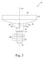
FIG. 3 is a side elevational view of another glenoid component. -
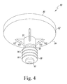
FIG. 4 is a bottom perspective view of the glenoid component ofFIG. 3 . -
FIG. 5 is a bottom perspective view of another glenoid component. -
FIG. 6 is a bottom perspective view of another glenoid component. -
FIG. 7 is a bottom elevational view of the glenoid component ofFIG. 6 and showing a shape of fins that extend outwardly from an anchor peg of the glenoid component. -
FIG. 8 is a perspective view depicting a glenoid surface of a scapula with a hole for securing a glenoid component to the glenoid surface. -
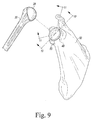
FIG. 9 is a partial exploded perspective view depicting the glenoid component ofFIG. 1 secured within the glenoid surface ofFIG. 8 and further showing a humeral component. -
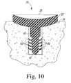
FIG. 10 is a cross-sectional view taken generally along the lines 10-10 ofFIG. 9 and depicting deflection of fins of the glenoid component ofFIGS. 1 and2 after securing the glenoid component within the glenoid surface. -
FIG. 11 is a cross-sectional view taken generally along the lines 11-11 ofFIG. 9 and depicting a sample level of interference between the fins of the glenoid component ofFIGS. 1 and2 and walls forming the hole formed within the glenoid surface. -
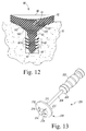
FIG. 12 is a cross-section view similar to that ofFIG. 10 and depicting the glenoid component ofFIG. 3 secured within the glenoid surface. -
FIG. 13 is a perspective view of a tool that may be used to prepare the glenoid surface prior to securing the glenoid component ofFIG. 3 thereto. -
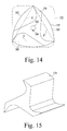
FIG. 14 is a diagrammatic view of an orthopaedic surgical tool having a cutting bit configured to make a square-shaped hole. -
FIG. 15 is a perspective view of the cutting bit of the orthopaedic surgical tool ofFIG. 14 . - Terms representing anatomical references, such as anterior, posterior, medial, lateral, superior and inferior are used in this document to refer to both the orthopaedic implants described herein and a patient's natural anatomy. Such terms have well-understood meanings in both the study of anatomy and the field of orthopaedics. Use of such anatomical reference terms in this document is intended to be consistent with their well-understood meanings unless noted otherwise.
- Referring to the drawings,
FIGS. 1 and2 show apolymer glenoid component 20 which includes abody 22 having a generallyconvex surface 24 and a generallyconcave surface 26 opposite theconvex surface 24. Theconvex surface 24 generally abuts or otherwise contacts at least a portion of the glenoid surface of the scapula. Thebody 22 of theglenoid component 20 generally has a shaped that is generally circular, such that theconcave surface 26 generally forms a spherical surface. In this manner, theconcave surface 26 of thebody 22 provides a smooth bearing surface upon which thehead 28 articulates and which generally matches the shape of thespherical head 28. - The
glenoid component 20 also includes ananchor peg 40 secured to and extending generally orthogonal to theconvex surface 24 of thebody 22. As shown inFIGS. 1 and2 , theanchor peg 40 includes acylindrical shaft 42 and a taperedhead 46 at an end of thecylindrical shaft 42 that functions as a lead-in to facilitate insertion into ahole 48 drilled or otherwise formed in a glenoid surface 50 (as shown inFIGS. 8 and9 ) of a patient'sscapula 52. Theanchor peg 40 may include a first cylindrical shaft segment extending from theconvex surface 24 and having a first diameter and a second cylindrical shaft segment extending from the first cylindrical shaft segment and having a second diameter less than the first diameter, as seen inFIGS. 1 and2 . Alternatively, theanchor peg 40 may have a single diameter throughout a length of thecylindrical shaft 42. - The anchor peg 40 further includes a plurality of flexible
radial fins 60 extending outwardly from anend 62 of theanchor peg 40. Thefins 60 function to secure theglenoid component 20 within theglenoid surface 50. In addition, the flexible and deformable nature of theradial fins 60 extending from theanchor peg 40 allow thefins 60 to deform upon insertion of theanchor peg 40 into thehole 48, thereby creating resistance to extraction of the anchor peg 40 from thehole 48 once fully inserted therein. - The
fins 60 ofglenoid component 20, as best seen inFIGS. 1 and2 , are generally square-shaped withrounded corners 62. Thefins 60 have a size and shape that creates an interference with walls forming thehole 48 that prevents easy removal of theglenoid component 20 from theglenoid surface 50 and prevents rotation of theglenoid component 20 without the use of a stabilizing peg, as will be discussed in greater detail below. -
FIGS. 3 and4 show a secondglenoid component 80 which is similar to theglenoid component 20 ofFIGS. 1 and2 in that it includes abody 82 with opposing generally convex and generallyconcave surfaces glenoid component 20 also includes ananchor peg 90 with acylindrical shaft 91 and atapered end 92. One manner in which theglenoid component 80 shown inFIGS. 3 and4 is different from theglenoid component 20 shown inFIGS. 1 and2 is that it includes a plurality of generallycircular fins 96 extending outwardly from anend 98 of theanchor peg 90. - The
glenoid component 80 includes a plurality ofgussets 100 extending downwardly from theconvex surface 84 and outwardly from theanchor peg 90 adjacent theconvex surface 84 of thebody 82. Thegussets 100 are also generally orthogonal to theconvex surface 84 and theanchor peg 90 and extend outwardly from the peg 90 a distance greater than thefins 96 extend from thepeg 90. An outerangled edge 102 of eachgusset 100 extends between and is integrally attached to theconvex surface 84 and theanchor peg 90. The gussets are spaced about alongitudinal axis 104 of theanchor peg 90 with about ninety degrees betweenadjacent gussets 100. - When the
glenoid component 80 is installed within theglenoid surface 50, thegussets 100 are pressed into theglenoid surface 50 surrounding theanchor peg 90 and below theconvex surface 84 of thebody 82, thereby preventing rotation of theglenoid component 80 without the use of a stabilizing peg. Installation and functionality of the glenoid component will be discuss in greater detail below with reference toFIG. 13 . - While four
gussets 100 are shown in theglenoid component 80 ofFIGS. 3 and4 , one ormore gussets 100 may be used. For example, asingle gusset 100 may be used, or eightgussets 100 may be used. The number ofgussets 100 that are used may be determined based on the ability of thosegussets 100 to prevent rotation of theglenoid component 80, the cost ofadditional gussets 100, and/or other factors. - A third
glenoid component 120 is shown inFIG. 5 . Theglenoid component 120 is similar to theglenoid component 80 ofFIGS. 3 and4 and similar features will be numbered similarly. The main difference is that theglenoid component 120 does not include gussets, but rather, includes a stabilizingpeg 122 extending outwardly from theconvex surface 84. The stabilizingpeg 122 is spaced between theanchor peg 90 and anouter edge 124 of thebody 82. While one stabilizingpeg 122 is shown, other stabilizingpegs 122 may be spaced about theconvex surface 84. - The stabilizing
peg 122 prevents thebody 82 of theglenoid component 120 from moving a plane perpendicular to theanchor peg 90 and prevent rotational movement of theglenoid component 120. Generally, the stabilizingpeg 122 is shorter than theanchor peg 90. Moreover, if multiple stabilizingpegs 122 are utilized, one or more of the stabilizingpegs 122 may be shorter than the others, although other configurations may be used. - While the
body 82, theanchor peg 90, and the stabilizingpeg 122 of theglenoid component 120 are shown as being integral, one or more of theanchor peg 90 or stabilizingpeg 122 may be separately secured to thebody 82. Any number of anchor pegs 90 or stabilizingpegs 122 may be used. Theanchor peg 90 may include any features that aid in inserting theanchor peg 90 into a hole or retaining theanchor peg 90 within a hole. The locations of the anchor peg(s) 90 and/or stabilizing peg(s) 122 may be modified. - In the component shown in
FIG. 5 , one or more secondary holes (not shown) would be formed within theglenoid surface 50 and spaced between thehole 48 and an outer edge of theglenoid surface 50. The secondary holes may have a size and shape that conforms to the stabilizing peg(s) 122. - A fourth
glenoid component 150 is depicted inFIG. 6 . Theglenoid component 150 is similar to theglenoid component 80 ofFIGS. 3 and4 . In particular, theglenoid component 150 includes asimilar body 82 with convex andconcave surfaces anchor peg 90 having acylindrical shaft 91 and atapered end 92 and extending outwardly and transversely to theconvex surface 84. Theglenoid component 150 further includes a plurality offins 152 extending outwardly from an end of theanchor peg 90. Upon insert of theanchor peg 90 into thehole 48, portions of thefins 152 deflect outwardly (toward an opening of the hole 48), thereby preventing rotation of theglenoid component 150 without the use of a stabilizing peg. - Each of the
fins 152 is generally disc-shaped and includes two opposingcutouts 154. Thecutouts 154 are generally triangular in shape and are generally symmetrical about anaxis 155 that bisects thefins 152. Optionally, thecutouts 154 may be asymmetrical. Eachcutout 154 includes first andsecond legs first leg 156 of eachcutout 154 extends at an angle B with respect to aline 160 tangent to an outer end of thefirst leg 156 and thesecond leg 158 of eachcutout 154 extends at an angle C with respect to aline 162 tangent to an outer end of thesecond leg 158. Optionally, thecutouts 154 may be formed of another shape, for example, square-shaped or U-shaped. Thecutouts 154 allow bone to grow between thefins 152 in two planes. While twocutouts 154 are depicted, any number ofcutouts 154 is possible. - The glenoid components shown and described herein may be made of a polymeric material, for example, a polyethylene. One example of a suitable polyethylene is ultrahigh molecular weight polyethylene (UHMWPE). In addition to polymers, the glenoid components may be made from ceramic, metal, or a composite material. Examples of these materials include alumina, zirconia, and alumina/zirconia composite or other composite materials.
- A method of securing the
glenoid component 20 ofFIGS. 1 and2 to theglenoid surface 50 of thescapula 52 will now be discussed in detail with reference toFIGS. 8 to 11 . A drill is used to bore thehole 48 through theglenoid surface 50 and into thescapula 52 and theanchor peg 40 of theglenoid component 20 is then press fitted or otherwise interference fitted into thehole 48. During installation, therounded corners 62 and/or side edges 170 between therounded corners 62 of the square-shapedfins 96 deflect outwardly (or toward an opening of the hole 48), thereby creating an interference with a wall forming the hole that prevents rotational movement of theglenoid component 150 and prevents theglenoid component 20 from moving in a plane perpendicular to theanchor peg 40. While thehole 48 is depicted herein as having a circular cross-section, the hole may optionally have different cross-sections for any of the devices disclosed herein, for example, a square-shaped cross section. - As can be seen in
FIG. 11 , which depicts a range of interference between thefins 60 and a wall forming thehole 48, the square shape of thefins 60 provides a greater interference at thecorners 62 of thefins 60 than at the side edges 170 of thefins 96. In one arrangement, an interference between the side edges 170 of thefins 60 and the wall of thehole 48 is between about 0.25 mm and about 2 mm and an interference between thecorners 62 of thefins 60 and the wall of thehole 48 is between about 0.5 mm and about 3 mm. In another construction, a width of thesquare fins 60 can be greater than a diameter of thehole 48. - The deflection of the
fins 60 upon insertion of theglenoid component 20 into thehole 48 is depicted inFIG. 10 . In particular, thecorners 62 of thefins 60 are deflected outwardly a greater distance than the side edges 170 of thefins 60 are deflected due to the difference in overall interference. - If the hole in which the
glenoid component 20 is installed has a square-shaped cross-section, ahole 172 maybe be created utilizing a tool having abit 174 with a general profile of aReuleux triangle 176, as seen inFIGS. 14 and 15 . In particular, aReuleux triangle 176 is created by starting with an equilateral triangle 178 with sides of length S. With a radius equal to S and a centre at a vertex of the triangle 178, threearcs 180 are drawn to form theReuleux triangle 176. Thebit 174, as noted above, has an outer profile that forms theReuleux triangle 176, such that, when the bit is rotated about acircle 182 starting at acentre 184 of the equilateral triangle 178, a square-shapedhole 172 with rounded corners is formed. Theglenoid component 20 is secured in the same manner when thehole 172 with a square-shaped cross-section is used. A length of a side of the square forming thefins 96 may be greater than a length of a side of the square forming thehole 172, thereby forming an interference fit. Upon insertion of theglenoid component 20, therounded corners 62 and the side edges 170 of thefins 96 deflect outwardly (toward an opening of the hole 172). The square shapes would prevent rotation of theglenoid component 20. - Methods of securing the
glenoid component 80 ofFIGS. 3 and4 to theglenoid surface 50 of thescapula 52 will now be discussed in detail with reference toFIGS. 12 and 13 . Ahole 48 is bored into theglenoid surface 50 of thescapula 52 in any manner known in the art. Atool 200 as shown inFIG. 13 may then be used to create slots within theglenoid surface 50 surrounding thehole 48. Thetool 200 generally includes ahandle 202, arod 204 extending from anend 206 of thehandle 202, and apunch 208 attached to anend 210 of therod 204. Thepunch 208 includes a plate, for example, adisc 212 having acylinder 214 extending from asurface 216 of thedisc 212 opposite therod 204. Thecylinder 214 is shaped and sized to have a diameter that interferes with thehole 48. In particular, thecylinder 214 has a diameter that is larger than a diameter than thehole 48 and smaller than a diameter of the fins of a glenoid component that fits within thehole 48.Triangular gussets 218 extend outwardly from thecylinder 214. Thegussets 218 are similar in size, shape, and number to thegussets 100 of theglenoid component 80. In particular, thegussets 218 are generally orthogonal to thedisc 212 and extend outwardly and are generally orthogonal to thecylinder 214. Eachgusset 218 is also disposed about 90 degrees around thecylinder 214 from anadjacent gusset 218. Should more orless gussets 100 be formed within a glenoid component, thetool 200 may be modified accordingly. - The
tool 200 is grasped by thehandle 202, thecylinder 214 of thetool 200 is inserted into thehole 48, and pressure is exerted on thetool 200 toward theglenoid surface 50, thereby creating slots in theglenoid surface 50 corresponding to thegussets 218. The anchor peg 90 of theglenoid component 80 may then be inserted into thehole 48, in the manner described above, until thegussets 218 are disposed within the slots created by thetool 200. - The
glenoid component 80 may be secured to theglenoid surface 50 without the use of thetool 200. In such a component, theanchor peg 90 of theglenoid component 80 would be inserted into thehole 48 and thegussets 100 would be driven into theglenoid surface 50, thereby creating the slots in which thegussets 100 are disposed. - The
glenoid component 120 ofFIG. 5 is secured to theglenoid surface 50 in a manner similar to that of theglenoid component 20 except that a secondary hole is created and, during installation of theglenoid component 120, the stabilizingpeg 122 is aligned with and inserted into the secondary hole. - The anchor peg 90 of the
glenoid component 150 ofFIG. 6 is also secured to theglenoid surface 50 in a manner similar to that of theglenoid component 20. During installation, thecutouts 154 in thefins 152 of theglenoid component 150 allow thefins 152 to deflect outwardly (or toward an opening of the hole 48), thereby creating an interference with a wall forming the hole that prevents rotational movement of theglenoid component 150 and movement of theglenoid component 150 in a plane perpendicular to theglenoid component 150. - The configurations of the fins and/or gussets as shown and described herein eliminate the need for the use of bone cement to secure the anchor peg to the
glenoid surface 50 of thescapula 52, thereby reducing the complexity of a typical shoulder replacement procedure. - While the glenoid components shown in the figures and described in detail include have a generally circular configuration, as described above, the glenoid component might have other configurations; for example, it might be oval-shaped. One advantage provided by the glenoid components having a circular configuration is that the glenoid component does not have to be aligned in a specific position or orientation.
Claims (14)
- A glenoid component for securement to a glenoid surface of a scapula so as to provide a bearing surface for a head portion of a humerus, the glenoid component comprising:a body portion having (i) a first surface adapted to contact the glenoid surface of a scapula and (ii) a second surface configured to receive the head portion of the humerus,an anchor peg for penetrating the glenoid surface of the scapula so as to secure the body portion to the glenoid surface of the scapula, in which the anchor peg includes (i) a cylindrical shaft extending from the first surface of the body portion and (ii) a fin secured to and extending outwardly from the cylindrical shaft, in which the fin includes at least one cutout configured to allow the fin to deflect outwardly along a hole in which the glenoid component is secured, thereby preventing rotation of the glenoid component.
- The glenoid component of claim 1, further including first and second opposing cutouts, in which each of the cutouts includes a first leg and a second leg forming generally triangular cutouts.
- The glenoid component of claim 2, in which the cutouts are symmetrical about an axis that bisects the fins.
- The glenoid component of claim 2, in which the body portion of the glenoid component is generally circular.
- The glenoid component of claim 1, further including first and second opposing cutouts, in which each of the cutouts is generally U-shaped.
- A glenoid component for securement to a glenoid surface of a scapula so as to provide a bearing surface for a head portion of a humerus, the glenoid component comprising:a body portion having (i) a first surface adapted to contact the glenoid surface of a scapula and (ii) a second surface configured to receive the head portion of the humerus, andan anchor peg for penetrating the glenoid surface of the scapula so as to secure the body portion to the glenoid surface of the scapula, in which the anchor peg includes (i) a cylindrical shaft extending from the first surface of the body portion and (ii) a fin secured to and extending outwardly from the cylindrical shaft, the fin being generally square-shaped.
- The glenoid component of claim 6, further including a plurality of generally square-shaped fins secured to and extending outwardly from the cylindrical shaft of the anchor peg, in which the generally square-shaped fins preferably have rounded corners.
- A glenoid component for securement to a glenoid surface of a scapula so as to provide a bearing surface for a head portion of a humerus, the glenoid component comprising:a body portion having (i) a first surface adapted to contact the glenoid surface of a scapula and (ii) a second surface configured to receive the head portion of the humerus,an anchor peg for penetrating the glenoid surface of the scapula so as to secure the body portion to the glenoid surface of the scapula, in which the anchor peg includes (i) a cylindrical shaft extending from the first surface of the body portion and (ii) a fin secured to and extending outwardly from the cylindrical shaft, andat least one gusset secured to and extending downwardly from the first surface of the body portion and secured to and extending outwardly from the cylindrical shaft of the anchor peg.
- The glenoid component of claim 8, in which an angled edge is formed by the gusset and extends between the first surface of the body portion and the anchor peg, in which the angled edge of the gusset is configured to be driven into the glenoid surface of the scapula to prevent rotation of the glenoid component.
- The glenoid component of claim 9, further including a plurality of gussets secured to and extending downwardly from the first surface of the body portion and secured to and extending outwardly from the cylindrical shaft of the anchor peg.
- The glenoid component of claim 10, in which the gussets are orthogonal to the first surface of the body portion and the cylindrical shaft of the anchor peg.
- A tool for preparing a glenoid surface of a scapula, the tool comprising:a handle, anda punch operatively connected to the handle, in which the fin punch includes a plate having a cylinder extending from the disc and at least one gusset extending outwardly from the cylinder.
- The tool of claim 12, further including four gussets extending outwardly from the cylinder.
- The tool of claim 13, in which the gussets are generally orthogonal to the disc and extend outwardly and are orthogonal to the cylinder and in which each of the four gussets is disposed about 90 degrees from an adjacent gusset.
Applications Claiming Priority (3)
| Application Number | Priority Date | Filing Date | Title |
|---|---|---|---|
| US201261665633P | 2012-06-28 | 2012-06-28 | |
| US13/790,633 US20140005789A1 (en) | 2012-06-28 | 2013-03-08 | Modified Glenoid Components and Methods of Installing Same |
| EP13174071.4A EP2679199B1 (en) | 2012-06-28 | 2013-06-27 | Modified glenoid component |
Related Parent Applications (2)
| Application Number | Title | Priority Date | Filing Date |
|---|---|---|---|
| EP13174071.4A Division-Into EP2679199B1 (en) | 2012-06-28 | 2013-06-27 | Modified glenoid component |
| EP13174071.4A Division EP2679199B1 (en) | 2012-06-28 | 2013-06-27 | Modified glenoid component |
Publications (2)
| Publication Number | Publication Date |
|---|---|
| EP3075358A1 true EP3075358A1 (en) | 2016-10-05 |
| EP3075358B1 EP3075358B1 (en) | 2018-06-06 |
Family
ID=48699617
Family Applications (2)
| Application Number | Title | Priority Date | Filing Date |
|---|---|---|---|
| EP16166893.4A Active EP3075358B1 (en) | 2012-06-28 | 2013-06-27 | Modified glenoid component |
| EP13174071.4A Active EP2679199B1 (en) | 2012-06-28 | 2013-06-27 | Modified glenoid component |
Family Applications After (1)
| Application Number | Title | Priority Date | Filing Date |
|---|---|---|---|
| EP13174071.4A Active EP2679199B1 (en) | 2012-06-28 | 2013-06-27 | Modified glenoid component |
Country Status (5)
| Country | Link |
|---|---|
| US (3) | US20140005789A1 (en) |
| EP (2) | EP3075358B1 (en) |
| JP (2) | JP6173793B2 (en) |
| CN (1) | CN103519923B (en) |
| AU (2) | AU2013206573B2 (en) |
Families Citing this family (39)
| Publication number | Priority date | Publication date | Assignee | Title |
|---|---|---|---|---|
| US20030065397A1 (en) | 2001-08-27 | 2003-04-03 | Hanssen Arlen D. | Prosthetic implant support structure |
| US7892288B2 (en) | 2001-08-27 | 2011-02-22 | Zimmer Technology, Inc. | Femoral augments for use with knee joint prosthesis |
| US20230080207A1 (en) | 2005-02-25 | 2023-03-16 | Shoulder Innovations, Inc. | Methods and devices for less invasive glenoid replacement |
| US8778028B2 (en) | 2005-02-25 | 2014-07-15 | Shoulder Innovations, Inc. | Methods and devices for less invasive glenoid replacement |
| AU2011258241A1 (en) | 2010-05-26 | 2013-01-10 | Orbis Medical Group Llc | Implantable prostheses |
| FR2971144A1 (en) | 2011-02-08 | 2012-08-10 | Tornier Sa | GLENOIDAL IMPLANT FOR SHOULDER PROSTHESIS AND SURGICAL KIT |
| WO2012125704A2 (en) * | 2011-03-14 | 2012-09-20 | Topsfield Medical Gmbh | Implantable glenoid prostheses |
| US20140005789A1 (en) * | 2012-06-28 | 2014-01-02 | Depuy Products, Inc. | Modified Glenoid Components and Methods of Installing Same |
| US9962266B2 (en) | 2015-09-11 | 2018-05-08 | Deltoid, Llc | Arthroplasty components |
| US10433969B2 (en) | 2013-12-30 | 2019-10-08 | United Orthopedic Corp. | Arthroplasty implants and methods for orienting joint prosthesis |
| EP3777777B1 (en) | 2014-01-03 | 2023-04-05 | Howmedica Osteonics Corp. | Glenoid implant for a shoulder prosthesis |
| US20150272741A1 (en) * | 2014-03-26 | 2015-10-01 | Biomet Manufacturing, Llc | Press-fit glenoid with peripheral compression pegs |
| US20150289984A1 (en) * | 2014-04-15 | 2015-10-15 | Matthew D. BUDGE | Total Shoulder Arthroplasty Prosthesis |
| US9681960B2 (en) | 2014-05-16 | 2017-06-20 | Howmedica Osteonics Corp. | Guides for fracture system |
| US10575968B2 (en) | 2014-05-16 | 2020-03-03 | Howmedica Osteonics Corp. | Guides for fracture system |
| FR3021864B1 (en) * | 2014-06-06 | 2019-10-25 | In2Bones | SURGICAL IMPLANT, IMPLEMENT TOOL, SURGICAL KIT AND METHOD FOR MANUFACTURING THE SAME |
| US10492926B1 (en) | 2014-09-04 | 2019-12-03 | Shoulder Innovations, Inc. | Alignment guide for humeral or femoral stem replacement prostheses |
| US9713533B2 (en) * | 2014-12-02 | 2017-07-25 | Biomet Manufacturing, Llc | In-line pegged hybrid glenoid |
| GB201505212D0 (en) * | 2015-03-26 | 2015-05-13 | Imp Innovations Ltd | Prosthetic glenoid component |
| EP3291768B1 (en) * | 2015-04-24 | 2019-11-27 | Biomet Manufacturing, LLC | Patient-specific augmented glenoid systems |
| US10722374B2 (en) | 2015-05-05 | 2020-07-28 | Tornier, Inc. | Convertible glenoid implant |
| USD835276S1 (en) | 2015-09-11 | 2018-12-04 | United Orthopedic Corporation | Keeled glenoid |
| US11833055B2 (en) | 2016-02-28 | 2023-12-05 | Integrated Shoulder Collaboration, Inc. | Shoulder arthroplasty implant system |
| US10172714B2 (en) | 2016-02-28 | 2019-01-08 | Consortium Of Focused Orthopedists, Llc | Shoulder arthroplasty implant system |
| JP7158106B2 (en) * | 2017-01-19 | 2022-10-21 | エンコア メディカル エル ピー | shoulder implant components |
| CN110191691B (en) | 2017-01-20 | 2022-03-22 | 拜欧米特制造有限责任公司 | Modular expansion component |
| US11076962B2 (en) | 2017-03-22 | 2021-08-03 | Howmedica Osteonics Corp. | Stemless metaphyseal humeral implant |
| EP3609440B1 (en) | 2017-04-14 | 2025-01-22 | Shoulder Innovations, Inc. | Total shoulder prosthesis having inset glenoid implant convertible from anatomic to reverse |
| WO2019213073A1 (en) | 2018-04-30 | 2019-11-07 | Shoulder Innovations, Llc | Inset/onlay glenoid, porous coated convertible glenoid, and humeral heads with textured undersides |
| CN113645924A (en) * | 2018-07-27 | 2021-11-12 | Ignite骨科有限责任公司 | Implants, systems, and methods of use thereof |
| US12295853B2 (en) | 2018-07-27 | 2025-05-13 | Depuy Ireland Unlimited Company | Implants, systems and methods of using the same |
| AU2020237088B2 (en) | 2019-03-11 | 2025-09-04 | Shoulder Innovations, Inc. | Total reverse shoulder systems and methods |
| AU2020276186C1 (en) | 2019-05-13 | 2022-07-21 | Howmedica Osteonics Corp. | Glenoid baseplate and implant assemblies |
| US20220265290A1 (en) | 2019-08-09 | 2022-08-25 | Howmedica Osteonics Corp. | Apparatuses and methods for implanting glenoid prostheses |
| AU2021202801A1 (en) | 2020-05-07 | 2021-11-25 | Howmedica Osteonics Corp. | Stemless metaphyseal humeral implant |
| JP7620116B2 (en) | 2021-02-26 | 2025-01-22 | ハウメディカ オステオニクス コーポレイション | Glenoid implant components and instruments thereof |
| EP4554521A4 (en) * | 2022-07-14 | 2026-03-25 | Howmedica Osteonics Corp | Monolithic baseplate |
| US20240024118A1 (en) * | 2022-07-22 | 2024-01-25 | Brandon Lee Thompson | A Mechanically Secured Plastic Patellar Prosthesis |
| WO2025171301A1 (en) * | 2024-02-09 | 2025-08-14 | Ignite Orthomotion, Llc | Implants, systems, instruments and methods of using the same |
Citations (4)
| Publication number | Priority date | Publication date | Assignee | Title |
|---|---|---|---|---|
| EP1323395A2 (en) * | 2001-12-31 | 2003-07-02 | Depuy Orthopaedics, Inc. | Augmented glenoid component having an interrupted surface |
| US20070219637A1 (en) * | 2006-03-20 | 2007-09-20 | Berelsman Brian K | Modular center pegged glenoid |
| US20100228352A1 (en) * | 2009-03-05 | 2010-09-09 | Tomier, Inc. | Glenoid implant anchor post |
| WO2011073169A1 (en) * | 2009-12-14 | 2011-06-23 | Tornier | Shoulder prosthesis glenoid component |
Family Cites Families (20)
| Publication number | Priority date | Publication date | Assignee | Title |
|---|---|---|---|---|
| US4349336A (en) * | 1977-10-26 | 1982-09-14 | Ipco Hospital Supply Corporation | Square dental anchor |
| DE8237288U1 (en) * | 1982-05-03 | 1985-09-12 | Waldemar Link Gmbh & Co, 2000 Hamburg | Femoral hip joint prosthesis |
| US4725280A (en) * | 1986-03-28 | 1988-02-16 | Laure Prosthetics, Inc. | Finger implant |
| US5571203A (en) | 1993-06-18 | 1996-11-05 | Masini; Michael A. | Bone-conserving hip system |
| FR2743295B1 (en) * | 1996-01-05 | 1998-04-03 | Landanger Landos | ANCILLARY FOR THE INSTALLATION OF A GLEN PROSTHESIS ON AN OMOPLATE |
| US6102934A (en) * | 1998-06-02 | 2000-08-15 | Li; Lehmann K. | Anchor tool and method and apparatus for emplacing anchor in a borehole |
| FR2794641B1 (en) * | 1999-06-09 | 2001-11-23 | Tornier Sa | HUMER PROSTHESIS |
| US6911047B2 (en) * | 2000-03-17 | 2005-06-28 | Depuy Orthopaedics, Inc. | Apparatus and method for securing a cementless glenoid component to a glenoid surface of a scapula |
| US6783549B1 (en) * | 2001-07-27 | 2004-08-31 | Biomet, Inc. | Modular humeral head resurfacing system |
| DE20120241U1 (en) * | 2001-12-14 | 2003-04-24 | KERAMED Medizintechnik GmbH, 07646 Mörsdorf | Endoprosthesis |
| US20050060039A1 (en) * | 2003-09-11 | 2005-03-17 | Jean-Maxwell Cyprien | Shoulder glenoid prosthesis with method and tools for implanting it |
| US8070820B2 (en) | 2003-10-08 | 2011-12-06 | Biomet Manufacturing Corp. | Shoulder implant assembly |
| EP1598034B1 (en) * | 2004-05-19 | 2011-03-30 | Zimmer GmbH | Glenoidal anchorage |
| US7922769B2 (en) * | 2004-09-27 | 2011-04-12 | Depuy Products, Inc. | Modular glenoid prosthesis and associated method |
| ITMI20061568A1 (en) | 2006-08-03 | 2008-02-04 | Plustek S R L | SHOULDER PROSTHESIS |
| US7691150B2 (en) * | 2006-12-15 | 2010-04-06 | Zimmer Technology, Inc. | Modular plate and keel provisionals |
| EP2299944A4 (en) * | 2008-07-17 | 2013-07-31 | Spinalmotion Inc | SYSTEM FOR INSTALLING ARTIFICIAL INTERVERTEBRAL DISCS |
| CA3064646C (en) * | 2009-04-17 | 2023-01-03 | Arthrosurface Incorporated | Glenoid resurfacing system and method |
| US8506569B2 (en) * | 2009-12-31 | 2013-08-13 | DePuy Synthes Products, LLC | Reciprocating rasps for use in an orthopaedic surgical procedure |
| US20140005789A1 (en) | 2012-06-28 | 2014-01-02 | Depuy Products, Inc. | Modified Glenoid Components and Methods of Installing Same |
-
2013
- 2013-03-08 US US13/790,633 patent/US20140005789A1/en not_active Abandoned
- 2013-06-27 AU AU2013206573A patent/AU2013206573B2/en active Active
- 2013-06-27 EP EP16166893.4A patent/EP3075358B1/en active Active
- 2013-06-27 JP JP2013135018A patent/JP6173793B2/en active Active
- 2013-06-27 EP EP13174071.4A patent/EP2679199B1/en active Active
- 2013-06-28 CN CN201310268086.1A patent/CN103519923B/en active Active
-
2015
- 2015-09-14 US US14/853,618 patent/US10702390B2/en active Active
-
2017
- 2017-07-05 JP JP2017131775A patent/JP6661578B2/en active Active
- 2017-12-07 AU AU2017272244A patent/AU2017272244B2/en active Active
-
2020
- 2020-07-07 US US16/922,912 patent/US11633285B2/en active Active
Patent Citations (4)
| Publication number | Priority date | Publication date | Assignee | Title |
|---|---|---|---|---|
| EP1323395A2 (en) * | 2001-12-31 | 2003-07-02 | Depuy Orthopaedics, Inc. | Augmented glenoid component having an interrupted surface |
| US20070219637A1 (en) * | 2006-03-20 | 2007-09-20 | Berelsman Brian K | Modular center pegged glenoid |
| US20100228352A1 (en) * | 2009-03-05 | 2010-09-09 | Tomier, Inc. | Glenoid implant anchor post |
| WO2011073169A1 (en) * | 2009-12-14 | 2011-06-23 | Tornier | Shoulder prosthesis glenoid component |
Also Published As
| Publication number | Publication date |
|---|---|
| US11633285B2 (en) | 2023-04-25 |
| JP6661578B2 (en) | 2020-03-11 |
| JP2017196475A (en) | 2017-11-02 |
| US20160095708A1 (en) | 2016-04-07 |
| JP6173793B2 (en) | 2017-08-02 |
| CN103519923A (en) | 2014-01-22 |
| CN103519923B (en) | 2018-01-19 |
| AU2013206573A1 (en) | 2014-01-16 |
| JP2014012134A (en) | 2014-01-23 |
| EP2679199B1 (en) | 2016-07-20 |
| US10702390B2 (en) | 2020-07-07 |
| AU2017272244B2 (en) | 2019-05-02 |
| EP3075358B1 (en) | 2018-06-06 |
| AU2013206573B2 (en) | 2017-09-07 |
| US20140005789A1 (en) | 2014-01-02 |
| US20200330237A1 (en) | 2020-10-22 |
| EP2679199A1 (en) | 2014-01-01 |
| AU2017272244A1 (en) | 2018-01-04 |
Similar Documents
| Publication | Publication Date | Title |
|---|---|---|
| US11633285B2 (en) | Modified glenoid components and methods of installing same | |
| JP7377864B2 (en) | Implants, systems and how to use them | |
| US11642223B2 (en) | Shoulder prosthesis components and assemblies | |
| JP6017467B2 (en) | Apparatus and method for post-rotation correction of shoulder arthroplasty | |
| EP2901971B1 (en) | Orthopaedic implant | |
| US10980640B2 (en) | System and method for implanting a secondary glenoid prosthesis | |
| EP1927328B1 (en) | Arthroscopic unicompartmental knee implantation system | |
| US8926709B2 (en) | Structures for use in orthopaedic implant fixation and methods of installation onto a bone | |
| US20240382316A1 (en) | Hybrid Metal-Backed Glenoid Component | |
| AU2649301A (en) | Apparatus and method for securing a cementless glenoid component to a glenoid surface of a scapula | |
| AU2006320207A1 (en) | Bone and cartilage implant delivery device | |
| EP3334386B1 (en) | Implant peg with multiple components | |
| EP3622919B1 (en) | Stemless metaphyseal humeral implant |
Legal Events
| Date | Code | Title | Description |
|---|---|---|---|
| PUAI | Public reference made under article 153(3) epc to a published international application that has entered the european phase |
Free format text: ORIGINAL CODE: 0009012 |
|
| AC | Divisional application: reference to earlier application |
Ref document number: 2679199 Country of ref document: EP Kind code of ref document: P |
|
| AK | Designated contracting states |
Kind code of ref document: A1 Designated state(s): AL AT BE BG CH CY CZ DE DK EE ES FI FR GB GR HR HU IE IS IT LI LT LU LV MC MK MT NL NO PL PT RO RS SE SI SK SM TR |
|
| 17P | Request for examination filed |
Effective date: 20170331 |
|
| RBV | Designated contracting states (corrected) |
Designated state(s): AL AT BE BG CH CY CZ DE DK EE ES FI FR GB GR HR HU IE IS IT LI LT LU LV MC MK MT NL NO PL PT RO RS SE SI SK SM TR |
|
| GRAP | Despatch of communication of intention to grant a patent |
Free format text: ORIGINAL CODE: EPIDOSNIGR1 |
|
| INTG | Intention to grant announced |
Effective date: 20180104 |
|
| GRAS | Grant fee paid |
Free format text: ORIGINAL CODE: EPIDOSNIGR3 |
|
| GRAA | (expected) grant |
Free format text: ORIGINAL CODE: 0009210 |
|
| AC | Divisional application: reference to earlier application |
Ref document number: 2679199 Country of ref document: EP Kind code of ref document: P |
|
| AK | Designated contracting states |
Kind code of ref document: B1 Designated state(s): AL AT BE BG CH CY CZ DE DK EE ES FI FR GB GR HR HU IE IS IT LI LT LU LV MC MK MT NL NO PL PT RO RS SE SI SK SM TR |
|
| REG | Reference to a national code |
Ref country code: GB Ref legal event code: FG4D |
|
| REG | Reference to a national code |
Ref country code: CH Ref legal event code: EP Ref country code: CH Ref legal event code: NV Representative=s name: E. BLUM AND CO. AG PATENT- UND MARKENANWAELTE , CH Ref country code: AT Ref legal event code: REF Ref document number: 1005220 Country of ref document: AT Kind code of ref document: T Effective date: 20180615 |
|
| REG | Reference to a national code |
Ref country code: IE Ref legal event code: FG4D |
|
| REG | Reference to a national code |
Ref country code: FR Ref legal event code: PLFP Year of fee payment: 6 |
|
| REG | Reference to a national code |
Ref country code: DE Ref legal event code: R096 Ref document number: 602013038756 Country of ref document: DE |
|
| REG | Reference to a national code |
Ref country code: NL Ref legal event code: MP Effective date: 20180606 |
|
| REG | Reference to a national code |
Ref country code: LT Ref legal event code: MG4D |
|
| PG25 | Lapsed in a contracting state [announced via postgrant information from national office to epo] |
Ref country code: BG Free format text: LAPSE BECAUSE OF FAILURE TO SUBMIT A TRANSLATION OF THE DESCRIPTION OR TO PAY THE FEE WITHIN THE PRESCRIBED TIME-LIMIT Effective date: 20180906 Ref country code: FI Free format text: LAPSE BECAUSE OF FAILURE TO SUBMIT A TRANSLATION OF THE DESCRIPTION OR TO PAY THE FEE WITHIN THE PRESCRIBED TIME-LIMIT Effective date: 20180606 Ref country code: NO Free format text: LAPSE BECAUSE OF FAILURE TO SUBMIT A TRANSLATION OF THE DESCRIPTION OR TO PAY THE FEE WITHIN THE PRESCRIBED TIME-LIMIT Effective date: 20180906 Ref country code: SE Free format text: LAPSE BECAUSE OF FAILURE TO SUBMIT A TRANSLATION OF THE DESCRIPTION OR TO PAY THE FEE WITHIN THE PRESCRIBED TIME-LIMIT Effective date: 20180606 Ref country code: ES Free format text: LAPSE BECAUSE OF FAILURE TO SUBMIT A TRANSLATION OF THE DESCRIPTION OR TO PAY THE FEE WITHIN THE PRESCRIBED TIME-LIMIT Effective date: 20180606 Ref country code: LT Free format text: LAPSE BECAUSE OF FAILURE TO SUBMIT A TRANSLATION OF THE DESCRIPTION OR TO PAY THE FEE WITHIN THE PRESCRIBED TIME-LIMIT Effective date: 20180606 Ref country code: CY Free format text: LAPSE BECAUSE OF FAILURE TO SUBMIT A TRANSLATION OF THE DESCRIPTION OR TO PAY THE FEE WITHIN THE PRESCRIBED TIME-LIMIT Effective date: 20180606 |
|
| PG25 | Lapsed in a contracting state [announced via postgrant information from national office to epo] |
Ref country code: RS Free format text: LAPSE BECAUSE OF FAILURE TO SUBMIT A TRANSLATION OF THE DESCRIPTION OR TO PAY THE FEE WITHIN THE PRESCRIBED TIME-LIMIT Effective date: 20180606 Ref country code: LV Free format text: LAPSE BECAUSE OF FAILURE TO SUBMIT A TRANSLATION OF THE DESCRIPTION OR TO PAY THE FEE WITHIN THE PRESCRIBED TIME-LIMIT Effective date: 20180606 Ref country code: HR Free format text: LAPSE BECAUSE OF FAILURE TO SUBMIT A TRANSLATION OF THE DESCRIPTION OR TO PAY THE FEE WITHIN THE PRESCRIBED TIME-LIMIT Effective date: 20180606 Ref country code: GR Free format text: LAPSE BECAUSE OF FAILURE TO SUBMIT A TRANSLATION OF THE DESCRIPTION OR TO PAY THE FEE WITHIN THE PRESCRIBED TIME-LIMIT Effective date: 20180907 |
|
| REG | Reference to a national code |
Ref country code: AT Ref legal event code: MK05 Ref document number: 1005220 Country of ref document: AT Kind code of ref document: T Effective date: 20180606 |
|
| PG25 | Lapsed in a contracting state [announced via postgrant information from national office to epo] |
Ref country code: NL Free format text: LAPSE BECAUSE OF FAILURE TO SUBMIT A TRANSLATION OF THE DESCRIPTION OR TO PAY THE FEE WITHIN THE PRESCRIBED TIME-LIMIT Effective date: 20180606 |
|
| PG25 | Lapsed in a contracting state [announced via postgrant information from national office to epo] |
Ref country code: PL Free format text: LAPSE BECAUSE OF FAILURE TO SUBMIT A TRANSLATION OF THE DESCRIPTION OR TO PAY THE FEE WITHIN THE PRESCRIBED TIME-LIMIT Effective date: 20180606 Ref country code: SK Free format text: LAPSE BECAUSE OF FAILURE TO SUBMIT A TRANSLATION OF THE DESCRIPTION OR TO PAY THE FEE WITHIN THE PRESCRIBED TIME-LIMIT Effective date: 20180606 Ref country code: EE Free format text: LAPSE BECAUSE OF FAILURE TO SUBMIT A TRANSLATION OF THE DESCRIPTION OR TO PAY THE FEE WITHIN THE PRESCRIBED TIME-LIMIT Effective date: 20180606 Ref country code: AT Free format text: LAPSE BECAUSE OF FAILURE TO SUBMIT A TRANSLATION OF THE DESCRIPTION OR TO PAY THE FEE WITHIN THE PRESCRIBED TIME-LIMIT Effective date: 20180606 Ref country code: IS Free format text: LAPSE BECAUSE OF FAILURE TO SUBMIT A TRANSLATION OF THE DESCRIPTION OR TO PAY THE FEE WITHIN THE PRESCRIBED TIME-LIMIT Effective date: 20181006 Ref country code: CZ Free format text: LAPSE BECAUSE OF FAILURE TO SUBMIT A TRANSLATION OF THE DESCRIPTION OR TO PAY THE FEE WITHIN THE PRESCRIBED TIME-LIMIT Effective date: 20180606 Ref country code: RO Free format text: LAPSE BECAUSE OF FAILURE TO SUBMIT A TRANSLATION OF THE DESCRIPTION OR TO PAY THE FEE WITHIN THE PRESCRIBED TIME-LIMIT Effective date: 20180606 |
|
| PG25 | Lapsed in a contracting state [announced via postgrant information from national office to epo] |
Ref country code: SM Free format text: LAPSE BECAUSE OF FAILURE TO SUBMIT A TRANSLATION OF THE DESCRIPTION OR TO PAY THE FEE WITHIN THE PRESCRIBED TIME-LIMIT Effective date: 20180606 Ref country code: IT Free format text: LAPSE BECAUSE OF FAILURE TO SUBMIT A TRANSLATION OF THE DESCRIPTION OR TO PAY THE FEE WITHIN THE PRESCRIBED TIME-LIMIT Effective date: 20180606 |
|
| REG | Reference to a national code |
Ref country code: BE Ref legal event code: MM Effective date: 20180630 |
|
| REG | Reference to a national code |
Ref country code: DE Ref legal event code: R097 Ref document number: 602013038756 Country of ref document: DE |
|
| PG25 | Lapsed in a contracting state [announced via postgrant information from national office to epo] |
Ref country code: LU Free format text: LAPSE BECAUSE OF NON-PAYMENT OF DUE FEES Effective date: 20180627 Ref country code: MC Free format text: LAPSE BECAUSE OF FAILURE TO SUBMIT A TRANSLATION OF THE DESCRIPTION OR TO PAY THE FEE WITHIN THE PRESCRIBED TIME-LIMIT Effective date: 20180606 |
|
| PLBE | No opposition filed within time limit |
Free format text: ORIGINAL CODE: 0009261 |
|
| STAA | Information on the status of an ep patent application or granted ep patent |
Free format text: STATUS: NO OPPOSITION FILED WITHIN TIME LIMIT |
|
| 26N | No opposition filed |
Effective date: 20190307 |
|
| PG25 | Lapsed in a contracting state [announced via postgrant information from national office to epo] |
Ref country code: DK Free format text: LAPSE BECAUSE OF FAILURE TO SUBMIT A TRANSLATION OF THE DESCRIPTION OR TO PAY THE FEE WITHIN THE PRESCRIBED TIME-LIMIT Effective date: 20180606 Ref country code: SI Free format text: LAPSE BECAUSE OF FAILURE TO SUBMIT A TRANSLATION OF THE DESCRIPTION OR TO PAY THE FEE WITHIN THE PRESCRIBED TIME-LIMIT Effective date: 20180606 Ref country code: BE Free format text: LAPSE BECAUSE OF NON-PAYMENT OF DUE FEES Effective date: 20180630 |
|
| PG25 | Lapsed in a contracting state [announced via postgrant information from national office to epo] |
Ref country code: AL Free format text: LAPSE BECAUSE OF FAILURE TO SUBMIT A TRANSLATION OF THE DESCRIPTION OR TO PAY THE FEE WITHIN THE PRESCRIBED TIME-LIMIT Effective date: 20180606 |
|
| PG25 | Lapsed in a contracting state [announced via postgrant information from national office to epo] |
Ref country code: MT Free format text: LAPSE BECAUSE OF NON-PAYMENT OF DUE FEES Effective date: 20180627 |
|
| PG25 | Lapsed in a contracting state [announced via postgrant information from national office to epo] |
Ref country code: TR Free format text: LAPSE BECAUSE OF FAILURE TO SUBMIT A TRANSLATION OF THE DESCRIPTION OR TO PAY THE FEE WITHIN THE PRESCRIBED TIME-LIMIT Effective date: 20180606 |
|
| PG25 | Lapsed in a contracting state [announced via postgrant information from national office to epo] |
Ref country code: PT Free format text: LAPSE BECAUSE OF FAILURE TO SUBMIT A TRANSLATION OF THE DESCRIPTION OR TO PAY THE FEE WITHIN THE PRESCRIBED TIME-LIMIT Effective date: 20180606 |
|
| PG25 | Lapsed in a contracting state [announced via postgrant information from national office to epo] |
Ref country code: MK Free format text: LAPSE BECAUSE OF NON-PAYMENT OF DUE FEES Effective date: 20180606 Ref country code: HU Free format text: LAPSE BECAUSE OF FAILURE TO SUBMIT A TRANSLATION OF THE DESCRIPTION OR TO PAY THE FEE WITHIN THE PRESCRIBED TIME-LIMIT; INVALID AB INITIO Effective date: 20130627 |
|
| PGFP | Annual fee paid to national office [announced via postgrant information from national office to epo] |
Ref country code: DE Payment date: 20250429 Year of fee payment: 13 |
|
| PGFP | Annual fee paid to national office [announced via postgrant information from national office to epo] |
Ref country code: GB Payment date: 20250508 Year of fee payment: 13 |
|
| PGFP | Annual fee paid to national office [announced via postgrant information from national office to epo] |
Ref country code: FR Payment date: 20250508 Year of fee payment: 13 |
|
| PGFP | Annual fee paid to national office [announced via postgrant information from national office to epo] |
Ref country code: IE Payment date: 20250509 Year of fee payment: 13 |
|
| PGFP | Annual fee paid to national office [announced via postgrant information from national office to epo] |
Ref country code: CH Payment date: 20250701 Year of fee payment: 13 |