EP3075201B1 - Procédé d'allocation de tranches temporelles d'émission - Google Patents
Procédé d'allocation de tranches temporelles d'émission Download PDFInfo
- Publication number
- EP3075201B1 EP3075201B1 EP13898345.7A EP13898345A EP3075201B1 EP 3075201 B1 EP3075201 B1 EP 3075201B1 EP 13898345 A EP13898345 A EP 13898345A EP 3075201 B1 EP3075201 B1 EP 3075201B1
- Authority
- EP
- European Patent Office
- Prior art keywords
- network node
- ues
- serving
- listening
- network
- Prior art date
- Legal status (The legal status is an assumption and is not a legal conclusion. Google has not performed a legal analysis and makes no representation as to the accuracy of the status listed.)
- Active
Links
- 230000005540 biological transmission Effects 0.000 title claims description 57
- 238000000034 method Methods 0.000 title claims description 36
- 208000037918 transfusion-transmitted disease Diseases 0.000 claims description 66
- 238000004590 computer program Methods 0.000 claims description 8
- 238000004891 communication Methods 0.000 claims description 6
- 230000001413 cellular effect Effects 0.000 description 5
- 230000004044 response Effects 0.000 description 4
- 238000011161 development Methods 0.000 description 2
- 238000012986 modification Methods 0.000 description 2
- 230000004048 modification Effects 0.000 description 2
- 238000007630 basic procedure Methods 0.000 description 1
- 239000000969 carrier Substances 0.000 description 1
- 230000003247 decreasing effect Effects 0.000 description 1
- 238000005516 engineering process Methods 0.000 description 1
- 238000013507 mapping Methods 0.000 description 1
- 230000000116 mitigating effect Effects 0.000 description 1
- 238000010295 mobile communication Methods 0.000 description 1
- 230000003287 optical effect Effects 0.000 description 1
- 230000002085 persistent effect Effects 0.000 description 1
- 238000012545 processing Methods 0.000 description 1
- 230000011664 signaling Effects 0.000 description 1
- 239000007787 solid Substances 0.000 description 1
Images

Classifications
-
- H—ELECTRICITY
- H04—ELECTRIC COMMUNICATION TECHNIQUE
- H04W—WIRELESS COMMUNICATION NETWORKS
- H04W72/00—Local resource management
- H04W72/04—Wireless resource allocation
- H04W72/044—Wireless resource allocation based on the type of the allocated resource
- H04W72/0446—Resources in time domain, e.g. slots or frames
-
- H—ELECTRICITY
- H04—ELECTRIC COMMUNICATION TECHNIQUE
- H04B—TRANSMISSION
- H04B17/00—Monitoring; Testing
- H04B17/30—Monitoring; Testing of propagation channels
- H04B17/309—Measuring or estimating channel quality parameters
- H04B17/318—Received signal strength
-
- H—ELECTRICITY
- H04—ELECTRIC COMMUNICATION TECHNIQUE
- H04W—WIRELESS COMMUNICATION NETWORKS
- H04W28/00—Network traffic management; Network resource management
- H04W28/02—Traffic management, e.g. flow control or congestion control
- H04W28/0268—Traffic management, e.g. flow control or congestion control using specific QoS parameters for wireless networks, e.g. QoS class identifier [QCI] or guaranteed bit rate [GBR]
-
- H—ELECTRICITY
- H04—ELECTRIC COMMUNICATION TECHNIQUE
- H04W—WIRELESS COMMUNICATION NETWORKS
- H04W52/00—Power management, e.g. TPC [Transmission Power Control], power saving or power classes
- H04W52/04—TPC
- H04W52/30—TPC using constraints in the total amount of available transmission power
- H04W52/36—TPC using constraints in the total amount of available transmission power with a discrete range or set of values, e.g. step size, ramping or offsets
- H04W52/365—Power headroom reporting
-
- H—ELECTRICITY
- H04—ELECTRIC COMMUNICATION TECHNIQUE
- H04W—WIRELESS COMMUNICATION NETWORKS
- H04W72/00—Local resource management
- H04W72/20—Control channels or signalling for resource management
- H04W72/21—Control channels or signalling for resource management in the uplink direction of a wireless link, i.e. towards the network
-
- H—ELECTRICITY
- H04—ELECTRIC COMMUNICATION TECHNIQUE
- H04W—WIRELESS COMMUNICATION NETWORKS
- H04W72/00—Local resource management
- H04W72/50—Allocation or scheduling criteria for wireless resources
- H04W72/54—Allocation or scheduling criteria for wireless resources based on quality criteria
- H04W72/541—Allocation or scheduling criteria for wireless resources based on quality criteria using the level of interference
-
- H—ELECTRICITY
- H04—ELECTRIC COMMUNICATION TECHNIQUE
- H04W—WIRELESS COMMUNICATION NETWORKS
- H04W84/00—Network topologies
- H04W84/02—Hierarchically pre-organised networks, e.g. paging networks, cellular networks, WLAN [Wireless Local Area Network] or WLL [Wireless Local Loop]
- H04W84/04—Large scale networks; Deep hierarchical networks
- H04W84/042—Public Land Mobile systems, e.g. cellular systems
Definitions
- Various embodiments of the present disclosure relate to a method for allocating Time Transmission Intervals, TTI, during UpLink, UL, transmissions in a shared radio cell environment.
- the present disclosure also relates to a network node for performing said allocation method.
- a cellular network or mobile network is a network distributed over different land areas, which are called radio cells.
- Each radio cell is each served by at least one fixed-location base station.
- each radio cell uses a different set of frequencies in relation to its neighboring radio cells in order to avoid interference and provide guaranteed bandwidth within each radio cell.
- this traditional setup of cellular networks there are no problems with interference, since neighboring radio cells use different frequencies.
- heterogeneous networks using combined radio cells also called shared radio cells
- a radio macro cell covering a large area is complemented within said large area with for example radio pico-cells served by pico-base stations.
- the combined radio cell cellular network allows operators to configure multiple radio cells with partially overlapping coverage as one 'radio cell carrier'.
- the same downlink signal is transmitted on each downlink radio channel, and the uplink signal is jointly decoded from the different radio cells.
- These radio pico-cells may be used to cover blind spots underneath a macro sector, or to minimize the number of separate radio cell carriers required in coverage limited scenarios.
- the shared radio cell may have fewer radio cells in the Radio Network Controller, RNC, less mobility signaling, and smooth radio cell split if traffic increases.
- one drawback with this setup is that all User Equipments, UEs, belonging to the same combined or shared radio cell, i.e. either the radio macro cell or any of the radio pico-cells within the radio macro cell, have to share the same uplink load resource in this combined radio cell.
- TDM Time Division Multiplexing
- scheduling the chance for each UE to be scheduled without increased transmission latency and delay will decrease. This is due to the fact that the number of the served users in a shared radio cell environment is much greater than in a traditional cellular network.
- the shared radio cell environment will thus contribute to increasing connectivity for UEs, but may also create a bottleneck if there are many UEs within the shared radio cell environment.
- US 2012/093096 Nakano Toshihiko et al: "Interference Mitigation based on partial CSI feedback and overhearing in an OFDM heterogeneous system " and " Downlink power allocation with CSI overhearing in an OFDM macro/femtocell coexisting system " and US 20 I 0/099431 all disclose methods of power or grant allocation, or interference management in heterogeneous networks.
- US2006/092876 discloses method for scheduling uplink data transmission for mobile station in soft handover region in a mobile communication system.
- the invention is defined by the independent claims. Furthermore, the embodiments of the invention are those defined by the claims.
- One way to solve the above mentioned problem with transmission latency and delay is that UEs in the same shared radio cell environment are grouped together, wherein each group may be served by any one of the base station or micro base stations based on some available measure and each base station or micro base station then performs separate and independent load control and scheduling only for UEs that are grouped together and associated to that base station or micro base station. In this way it is possible with spatial reuse between user groups/base stations and each UE has a better chance to be scheduled.
- the inventors also realized that in order to further improve the performance of UL transmissions one has to consider interference between the different groups of UEs. UEs which have similar path gain to multiple base stations or micro base stations may generate fairly strong interference to the UEs served by other base stations or micro base stations. Accordingly, the problem to be solved is to diminish the interference during spatial reuse in a shared radio cell environment.
- a method performed by a network node for allocating Time Transmission Intervals, TTI, during uplink transmission is accomplished.
- the network node is one of several network nodes in a shared radio cell environment and serves a first radio cell and controls the other network nodes in the shared radio cell environment, which other network nodes serve other radio cells.
- Each network node serves a group of User Equipments, UEs, for uplink transmission and each network node acts as a serving network node for all UEs in the group served by said network node and as a listening network node for UEs served by other network nodes, if said network node receives UE transmissions from UEs served by other network nodes.
- the method comprises determining, for each serving network node, if it also acts as listening network node for UEs not served by this serving network node, and allocating TTIs such that the UE transmission for UEs having both a serving network node and one or more listening network nodes is coordinated by scheduling said UE transmission in the same TTI frame for the serving network node and said one or more listening network nodes in the shared radio cell environment.
- the method may according to exemplary embodiments further comprise, determining which network node acting both as serving network node and as listening network node within the shared radio cell environment that receives most UE transmissions, and in response thereto allocating TTIs for all UEs, for which this determined network node is either the serving network node or the listening network node prior to allocating TTIs for UEs of all other network nodes in the shared radio cell environment.
- the method further comprises determining which network node acting as both serving network node and as listening network node of the not yet scheduled network nodes within the shared radio cell environment that receives most UE transmissions, and in response thereto allocating TTIs for all UEs, for which this determined network node is either the serving network node or the listening network node , prior to allocating TTIs for UEs of the network nodes that have not previously been scheduled.
- the determination of listening network nodes may comprise measuring an uplink signal strength in the dedicated physical control channel, measuring a quality of probing pilots sent from the network node or measuring a load headroom.
- a network node for allocating Time Transmission Intervals, TTI, during uplink transmission is accomplished.
- the network node is one of several network nodes in a shared radio cell environment and serves a first radio cell and controls the other network nodes in the shared radio cell environment.
- the other network nodes serve other radio cells.
- Each network node serves a group of User Equipments, UEs, for uplink transmission and each network node acts as a serving network node for all UEs in the group served by said network node and as a listening network node for UEs served by other network nodes if said network node receives UE transmissions from UEs served by other network nodes.
- the network node comprises a communication interface arranged for wireless communication with said network nodes, a processor and a memory storing a software package comprising computer program code which, when run in the processor, causes the network node to determine, for each serving network node if it also acts as listening network node for UEs not served by the serving network node, and allocate TTIs such that the UE transmission for UEs having both a serving network node and one or more listening network nodes is coordinated by scheduling said UE transmission in the same TTI frame for the serving network node and said one or more listening network nodes in the shared radio cell environment.
- the network node may according to exemplary embodiments further be caused to determine which network node acting as both serving network node and as listening network node within the shared radio cell environment that receives most UE transmissions, and in response thereto allocate TTIs for all UEs, for which this determined network node is either the serving network node or the listening network node prior to allocating TTIs for UEs of all other network nodes in the shared radio cell environment.
- the network node may furthermore be caused to determine which network node acting as both serving network node and as listening network node of the not yet scheduled network nodes within the shared radio cell environment that receives most UE transmissions, and in response thereto allocate TTIs for all UEs, for which this determined network node is either the serving network node or the listening network node prior to allocating TTIs for UEs of network nodes that have not previously been scheduled.
- a TTI allocation method is advantageously achieved which diminishes the interference during spatial reuse in a shared radio cell environment.
- the method creates a good balance between spatial reuse and the orthogonality between different base stations in a shared radio cell environment, i.e. spatial reuse is adopted such that a of sufficient orthogonality achieved.
- the interference in for example a Wideband Code Division Multiple Access, WCDMA, uplink, is limited by the amount of tolerable interference that the common radio resource that is shared among the UEs is capable to handle.
- the tolerable interference is defined as the average interference over all the antennae.
- a relative measure of total interference is Rise over Thermal, RoT, i.e. total interference relative to thermal noise.
- RoT Rise over Thermal
- the UEs are non-orthogonal to each other, i.e. the UEs generate interference to each other even if they are within the same radio cell. Therefore the system needs to have an upper interference limitation, i.e. a limit where the radio cell RoT cannot be increased any more in order to achieve sufficient coverage at the radio cell border. This of course limits the maximum radio cell capacity. This limitation is also denoted as target RoT.
- a load factor represents a portion of an uplink interference that a specific channel of a specific UE generates.
- the load factor is defined as the interference from this specific UE on this specific channel divided by the total interference.
- the total load factor of different channels equals to the sum of load factors of each specific channel.
- a load controller estimates how the load resources in the radio cell are used and how much load resources that are available for the radio cell without the risk of exceeding the load target of that specific radio cell, which load target may be the RoT target.
- the load controller delivers an estimated available load headroom to a scheduler and the uplink scheduler determines the maximum data rate that can be supported for a specific UE in each radio cell so that the maximum available load room is sufficiently but not excessively used. This is also called load headroom to rate mapping.
- This type of controlling may be implemented by determining the supportable power offset between the channel to be scheduled and the D edicated P hysical C ontrol CH annel, DPCCH, which is a fixed rate channel. The supportable data rate is then determined based on the granted power offset.
- UE data transmissions may be separated in time by using a T ime D ivision M ultiplexing, TDM scheme.
- TDM scheme takes advantage of the ability to grant uplink transmissions for active UEs that are only valid for a specific H ybrid A utomatic R epeat R equest, HARQ, process.
- TDM scheduling may be used for performing soft handover in view of a serving radio cell. In non-serving radio cells or in listening radio cells the UEs are still code multiplexed with concurrent transmissions.
- a listening radio cell is a radio cell that receives UE transmissions from UEs already served by a serving radio cell. In order to properly decode the transmission from the UEs not served by the serving radio cell one would have to inform the listening cells about the TDM scheduling pattern for the non-served UEs. Since WCDMA in general is asynchronous, the HARQ processes in different radio cells will not be time aligned. This makes it complicated for a listening radio cell to determine in which HARQ process of the listening radio cell the UE is scheduled to transmit. It would be easier to schedule the UE in a C ode D ivision M ultiplexing, CDM, manner, but to the price of decreased orthgonality between UEs and users and increased intra-radio cell interference.
- each radio pico-cell operates as a separate radio cell in relation to the radio macro cell.
- the macro and the pico cell(s) are operated as one logical radio cell.
- the shared radio cell environment comprises a base station 10, a number of pico base stations 20A, 20B and 20C and UEs 30.
- the base station 10 serves a radio macro cell M, shown with an unbroken line and the pico base stations 20A, 20B and 20C serve radio pico-cells P shown with dotted lines.
- the pico base stations 20A, 20B and 20C serve radio pico-cells P shown with dotted lines.
- the pico base stations 20A, 20B and 20C serve radio pico-cells P shown with dotted lines.
- In total there are six UEs shown in figure 1 but in reality there are of course usually much more UEs 30 present. However, for illustration purposes and in the sake of simplicity it will be enough to show six UEs 30.
- the base station 10 is capable of serving all six UEs 30 within the radio macro cell M, and each pico base station 20A, 20B, and 20C may each serve a UE 30 that is within the borders of the radio pico-cell P, respectively.
- the UEs 30 may be grouped together in different groups depending on the base station 10, 20A, 20B or 20C that serves the UEs 30.
- the UEs 30 within the radio pico-cells P are served by its respective pico base station 20A, 20B and 20C the UEs that are not situated within any of the radio pico-cells P are served by the base station 10. How the transmissions between different UE 30 groups are coordinated will be described below in conjunction with figures 3 and 4 .
- base station and the pico base stations should only be interpreted as exemplary and could actually be any suitable network node such as a radio base station, an e volved N ode B , eNB, a h ome eNB, HeNB, a NB, a HNB, a pico, micro or femto base station.
- a radio base station an e volved N ode B , eNB, a h ome eNB, HeNB, a NB, a HNB, a pico, micro or femto base station.
- FIG. 2 a schematic view of an exemplary network node 10 is shown.
- the network nodes 20A, 20B,and 20C could be described in a corresponding way.
- the exemplary network node 10 comprises a controller (CTL) or a processor 23 that may be constituted by any suitable C entral P rocessing U nit, CPU, microcontroller, D igital S ignal P rocessor, DSP, etc., capable of executing a computer program comprising computer program code.
- the computer program may be stored in a memory (MEM) 24.
- the memory 24 may be any combination of a R ead A nd write M emory, RAM, and a R ead O nly M emory, ROM.
- the memory 24 may also comprise persistent storage, which, for example, can be any single one or combination of magnetic memory, optical memory, or solid state memory or even remotely mounted memory.
- the network node 10 further comprises a communication interface (i/f) 22 arranged for establishing a communication link with other devices or network nodes, such as entities in the core network or the backhaul network or the network nodes 20A, 20B and 20C.
- a communication interface (i/f) 22 arranged for establishing a communication link with other devices or network nodes, such as entities in the core network or the backhaul network or the network nodes 20A, 20B and 20C.
- a serving network node such as the base station 10
- the network node 10 may serve all UEs that are not within a radio pico-cell P, in this case three different UEs 30. These three UEs are grouped together. The three other UEs are placed in groups belonging to each radio pico-cell P, respectively. However, the transmissions of these last mentioned groups of UEs 30 may also be received and decoded by the base station 10, despite the fact that they have other network nodes serving them.
- the base station In the case where the base station also receives and decodes transmissions from other UEs not served by the base station 10 it will also be defined as a listening node for these UEs 30.
- the transmission from such UEs may generate strong interference to the UEs served by the base station. Therefore special care has to be taken in order to handle this high interference.
- the serving network node also acts as a listening network node, such as the strength of uplink signal in the DPCCH, the quality of probing pilots, the load headroom or the target RoT of the network node in question, as well as the traffic load served by each network node.
- the following examples may illustrate the different ways to determine if the serving network node also is a listening network node. For example, suppose that the estimated uplink signal strength from a UE received by its serving network node is S serve and that the quality of the probing pilot of the serving network node estimated by the UE is Q serve . The serving network node will always be regarded as the effective network node for effectively receiving the UE transmission. Another network node within the same shared radio cell M that is examined may be regarded as the listening network node of the UE if the following conditions are satisfied: S exam > S serve ⁇ k 1 and / or Q exam > Q serve ⁇ k 2 where:
- the load headroom as a determining parameter.
- the available load headroom for the serving network node and the network node to be examined are L serve and L exam respectively.
- the examined network node may be regarded as the listening network node of the UE if the following conditions are satisfied: S exam / S serve > L exam / L serve n 1 ⁇ p 1 and / or Q exam / Q serve > L exam / L serve n 2 ⁇ p 2 where: n 1 , n 2 , p 1 and p 2 are all configurable parameters. Equation (2) becomes the same as Equation (1), i.e. the judgment will only be based on signal strength and/or the probing pilot, if n 1 and/or n 2 are set to 0.
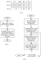
- Network node A is the serving network node for two UEs A 1 and A 2 and also acts as the listening network node for UEs BA and AC.
- Network node B is the serving network node for the UEs B 1 , B 2 , B 3 and B 4 and also acts as the listening network node for UEs BA and CB.
- Network node C is the serving network node for UE C 1 and also acts as listening network node for UEs AC and CB.
- One way to perform scheduling is to independently schedule all UEs for which the network node acts both as the serving network node and the listening network node in the same way.
- Network node A will schedule the four UEs A 1 , A 2 , BA and AC in the same way
- network node B will schedule the six UEs B 1 to B 4 , BA and CB in the same way
- network node C will schedule the three UEs C 1 , AC, and CB in the same way.
- each UE occupies the same number of (HARQ processes) TTIs if it is possible, there may be a risk of conflict between different network nodes as the following example illustrates.
- network node A UE BA and AC will each be allocated 2 TTIs
- network node B UE BA and CB will each be allocated 1 or 2 TTIs
- network node C UE AC and CB each will be allocated 2 or 3 TTIs and at least one of them will have 3 TTIs.
- UE AC and CB will be allocated 3 TTIs in the network node C, while these UEs AC and CB can only be allocated 2 TTIs in the other two network nodes A and B, conflict is unavoidable.
- An exemplary embodiment solves this problem by always allocating 1 TTI for the UEs where the serving network node also acts as a listening network node. This is a nice solution but may further be improved since the allocation of only 1 TTI may lead to unfairness, i.e. the data rate of the UEs received by listening network nodes may be too low.
- a further development is to coordinate the UE transmissions in a better way between the different network nodes.
- one of the network nodes within the shared radio cell environment will act as a controlling network node for the other network nodes.
- it may be any of the network nodes that acts as the controlling network node, such as the base station 10 or any of the pico base stations 20A, 20B or 20C.
- the coordination is performed between the network nodes in the same shared radio cell that also act as listening network nodes.
- the basic procedure of the coordination starts from the network node that serves and listens to the most number of UEs for which the allocation TTI(s) not yet has been performed.
- FIG. 4 To better illustrate the above coordination between and scheduling of the different network nodes an example will now be described in conjunction with figure 4 .
- the same network nodes the same UEs and the same UE grouping are used as in the example illustrated in figure 3 . It has first to be determined which network node that serves and listens to most UEs, i.e. network node B in this example. Thus, network node B is the network node to be scheduled first. It is assumed that UE BA and CB are allocated 1 TTI and 2 TTIs, respectively. The same allocation, i.e. the number and position of TTIs, will also be applied for UE BA in network node A and for UE CB in network node C.
- the UEs B 1 to B 3 are each allocated 1 TTI and UE B 4 is allocated 2 TTIs. After the allocation of TTIs for each UE the TTIs for the different UEs are scheduled in time. In this example all UEs having 1 TTI are scheduled first but there may be many other ways to schedule the UEs.
- network node A After the allocation and scheduling of network node B it will be determined which network node that serves and listens to the second most UEs, i.e. network node A in the present example.
- UE BA has already been scheduled in conjunction with the scheduling of network node B.
- UE AC is allocated 2 TTIs, which allocation then also will be applied in network node C.
- UE A 1 will be allocated 3 TTIs and UE A 2 will be allocated 2 TTIs.
- network node C Finally network node C will be scheduled.
- UE CB and AC have been previously scheduled, i.e. only UE C 1 is left to allocate and schedule. Apparently UE C 1 will get the remaining 4 TTIs.
- each network node may still schedule independently with the determined TTI allocation as in the example in figure 3 .
- the method starts with determining, in step 100, for each serving network node 10; 20A; 20B; 20C if it also acts as listening network node 10; 20A; 20B; 20C for UEs 30 not served by this serving network node 10; 20A; 20B; 20C.
- step 102 the method proceeds with allocating TTIs such that the UE transmission for UEs having both a serving network node 10; 20A; 20B; 20C and one or more listening network nodes 10; 20A; 20B; 20C is coordinated by scheduling said UE transmission in the same TTI frame for the serving network node 10; 20A; 20B; 20C and said one or more listening network nodes 10; 20A; 20B; 20C in the shared radio cell environment.
- step 200 is determining which network node 10; 20A; 20B; 20C both in the capacity as serving network node and as listening network node within the shared radio cell environment that receives the most UE transmissions and in step 202 allocating TTIs for all UEs, for which the determined network node 10; 20A; 20B; 20C is either the serving network node or the listening network node prior to allocating and scheduling TTIs for UEs of all other network nodes 10; 20A; 20B; 20C in the shared radio cell environment.
- step 204 the method continues with determining which network node 10; 20A; 20B; 20C in the capacity as both serving network node and as listening network node, of the not yet scheduled network nodes (10; 20A; 20B; 20C) within the shared radio cell environment, that receives most UE transmissions, and, in step 206 allocating TTIs for all UEs, for which this determined network node 10; 20A; 20B; 20C is either the serving network node or the listening network node, prior to allocating TTIs for UEs of the network nodes 10; 20A; 20B; 20C that have not previously been scheduled. This last step is repeated until all network nodes have been scheduled.
Landscapes
- Engineering & Computer Science (AREA)
- Computer Networks & Wireless Communication (AREA)
- Signal Processing (AREA)
- Quality & Reliability (AREA)
- Physics & Mathematics (AREA)
- Electromagnetism (AREA)
- Mobile Radio Communication Systems (AREA)
Claims (10)
- Procédé mis en œuvre par un nœud de réseau (10 ; 20 A ; 20B ; 20C) pour allouer des intervalles de temps de transmission, TTI, pendant une transmission en liaison montante, ledit nœud de réseau (10 ; 20A ; 20B ; 20C) étant l'un parmi plusieurs nœuds de réseau (10 ; 20A ; 20B ; 20C) dans un environnement de cellules radio partagées et desservant une première cellule radio et une commande des autres nœuds de réseau (10 ; 20A ; 20B ; 20C) dans l'environnement de cellules radio partagées, lesquels autres nœuds de réseau (10 ; 20A ; 20B ; 20C) desservent d'autres cellules radio, chaque nœud de réseau (10 ; 20A ; 20B ; 20C) desservant un groupe d'équipements utilisateur (30), UE, pour une transmission en liaison montante et chaque nœud de réseau (10 ; 20A ; 20B ; 20C) jouant le rôle de nœud de réseau de desserte (10 ; 20A ; 20B ; 20C) pour tous les UE (30) dans le groupe desservi par ledit nœud de réseau (10 ; 20A ; 20B ; 20C) et de nœud de réseau d'écoute (10 ; 20A ; 20B ; 20C), pour des UE (30) desservis par d'autres nœuds de réseau (10 ; 20A ; 20B ; 20C), si ledit nœud de réseau (10 ; 20A ; 20B ; 20C) reçoit des transmissions d'UE depuis des UE (30) desservis par d'autres nœuds de réseau (10 ; 20A ; 20B ; 20C), ledit procédé comprenant :le fait de déterminer (100), pour chaque nœud de réseau de desserte (10 ; 20A ; 20B ; 20C) s'il joue également le rôle de nœud de réseau d'écoute (10 ; 20A ; 20B ; 20C) pour des UE (30) non desservis par ce nœud de réseau de desserte (10 ; 20A ; 20B ; 20C), etl'allocation (102) de TTI de sorte que la transmission d'UE pour des UE ayant à la fois un nœud de réseau de desserte (10 ; 20A ; 20B ; 20C) et un ou plusieurs nœuds de réseau d'écoute (10 ; 20A ; 20B ; 20C) est coordonnée en planifiant ladite transmission d'UE dans la même trame de TTI pour le nœud de réseau de desserte (10 ; 20A ; 20B ; 20C) et ledit ou lesdits nœuds de réseau d'écoute (10 ; 20A ; 20B ; 20C) dans l'environnement de cellules radio partagées ; caractérisé en ce que le procédé comprend en outre :la détermination (200) du nœud de réseau (10 ; 20A ; 20B ; 20C) jouant le rôle à la fois de nœud de réseau de desserte (10 ; 20A ; 20B ; 20C) et de nœud de réseau d'écoute (10 ; 20A ; 20B ; 20C) au sein de l'environnement de cellules radio partagées qui reçoit la plupart des transmissions d'UE, etl'allocation (202) de TTI pour tous les UE, pour lesquels de nœud de réseau déterminé (10 ; 20A ; 20B ; 20C) est soit le nœud de réseau de desserte (10 ; 20A ; 20B ; 20C) soit le nœud de réseau d'écoute (10 ; 20A ; 20B ; 20C), avant une allocation de TTI pour des UE de tous les autres nœuds de réseau (10 ; 20A ; 20B ; 20C) dans l'environnement de cellules radio partagées.
- Procédé selon la revendication 1, comprenant en outre
la détermination (204) du nœud de réseau (10 ; 20A ; 20B ; 20C) jouant le rôle à la fois de nœud de réseau de desserte (10 ; 20A ; 20B ; 20C) et de nœud de réseau d'écoute (10 ; 20A ; 20B ; 20C), parmi les nœuds de réseau non encore planifiés (10 ; 20A ; 20B ; 20C) au sein de l'environnement de cellules radio partagées qui reçoit la plupart des transmissions d'UE, et
l'allocation (206) de TTI pour tous les UE, pour lesquels ce nœud de réseau déterminé (10 ; 20A ; 20B ; 20C) est soit le nœud de réseau de desserte (10 ; 20A ; 20B ; 20C) soit le nœud de réseau d'écoute (10 ; 20A ; 20B ; 20C), avant l'allocation de TTI pour des UE des nœuds de réseau (10 ; 20A ; 20B ; 20C) qui n'ont pas été précédemment planifiés. - Procédé selon l'une quelconque des revendications 1 à 2, dans lequel la détermination de nœuds de réseau d'écoute (10 ; 20A ; 20B ; 20C) comprend la mesure d'une force de signal de liaison montante dans le canal de commande physique dédié.
- Procédé selon l'une quelconque des revendications 1 à 3, dans lequel la détermination de nœuds de réseau d'écoute (10 ; 20A ; 20B ; 20C) comprend la mesure d'une qualité de pilotes de sondage envoyés depuis le nœud de réseau (10 ; 20A ; 20B ; 20C).
- Procédé selon l'une quelconque des revendications 1 à 4, dans lequel la détermination de nœuds de réseau d'écoute (10 ; 20A ; 20B ; 20C) comprend la mesure d'une marge de charge.
- Nœud de réseau (10 ; 20A ; 20B ; 20C) pour allouer des intervalles de temps de transmission, TTI, pendant une transmission en liaison montante, ledit nœud de réseau (10 ; 20A ; 20B ; 20C) étant l'un parmi plusieurs nœuds de réseau (10 ; 20A ; 20B ; 20C) dans un environnement de cellules radio partagées et desservant une première cellule radio et une commande des autres nœuds de réseau (10 ; 20A ; 20B ; 20C) dans l'environnement de cellules radio partagées, lesquels autres nœuds de réseau (10 ; 20A ; 20B ; 20C) desservent d'autres cellules radio, chaque nœud de réseau (10 ; 20A ; 20B ; 20C) desservant un groupe d'équipements utilisateur (30), UE, pour une transmission en liaison montante et chaque nœud de réseau (10 ; 20A ; 20B ; 20C) jouant le rôle de nœud de réseau de desserte (10 ; 20 A ; 20B ; 20C) pour tous les UE (30) dans le groupe desservi par ledit nœud de réseau (10 ; 20A ; 20B ; 20C) et de nœud de réseau d'écoute (10 ; 20A ; 20B ; 20C), pour des UE (30) desservis par d'autres nœuds de réseau (10 ; 20A ; 20B ; 20C), si ledit nœud de réseau (10 ; 20A ; 20B ; 20C) reçoit des transmissions d'UE depuis des UE desservis par d'autres nœuds de réseau (10 ; 20A ; 20B ; 20C), ledit nœud de réseau (10 ; 20 A ; 20B ; 20C) comprenant :une interface de communication (22) agencée pour une communication sans fil avec lesdits nœuds de réseau (10 ; 20A ; 20B ; 20C) ;un processeur (23) ;et une mémoire (24) stockant un progiciel comprenant un code de programme informatique qui, lorsqu'il est exécuté dans le processeur (23), amène le nœud de réseau (10 ; 20A ; 20B ; 20C) à :déterminer, pour chaque nœud de réseau de desserte (10 ; 20A ; 20B ; 20C) s'il joue également le rôle de nœud de réseau d'écoute (10 ; 20 A ; 20B ; 20C) pour des UE (30) non desservis par le nœud de réseau de desserte (10 ; 20A ; 20B ; 20C), etallouer des TTI de sorte que la transmission d'UE pour des UE ayant à la fois un nœud de réseau de desserte (10 ; 20A ; 20B ; 20C) et un ou plusieurs nœuds de réseau d'écoute (10 ; 20A ; 20B ; 20C) est coordonnée en planifiant ladite transmission d'UE dans la même trame de TTI pour le nœud de réseau de desserte (10 ; 20A ; 20B ; 20C) et ledit ou lesdits nœuds de réseau d'écoute (10 ; 20A ; 20B ; 20C) dans l'environnement de cellules radio partagées ;caractérisé en ce que le code de programme informatique est en outre configuré pour amener le nœud de réseau à :déterminer le nœud de réseau (10 ; 20A ; 20B ; 20C) jouant le rôle à la fois de nœud de réseau de desserte (10 ; 20A ; 20B ; 20C) et de nœud de réseau d'écoute (10 ; 20A ; 20B ; 20C) au sein de l'environnement de cellules radio partagées qui reçoit la plupart des transmissions d'UE, etallouer des TTI pour tous les UE, pour lesquels de nœud de réseau déterminé (10 ; 20A ; 20B ; 20C) est soit le nœud de réseau de desserte (10 ; 20A ; 20B ; 20C) soit le nœud de réseau d'écoute (10 ; 20A ; 20B ; 20C), avant une allocation de TTI pour des UE de tous les autres nœuds de réseau (10 ; 20A ; 20B ; 20C) dans l'environnement de cellules radio partagées.
- Nœud de réseau (10 ; 20A ; 20B ; 20C) selon la revendication 6, qui est en outre amené à
déterminer le nœud de réseau (10 ; 20A ; 20B ; 20C) jouant le rôle à la fois de nœud de réseau de desserte (10 ; 20A ; 20B ; 20C) et de nœud de réseau d'écoute (10 ; 20A ; 20B ; 20C), parmi les nœuds de réseau non encore planifiés (10 ; 20A ; 20B ; 20C) au sein de l'environnement de cellules radio partagées qui reçoit la plupart des transmissions d'UE, et
allouer des TTI pour tous les UE, pour lesquels ce nœud de réseau déterminé (10 ; 20A ; 20B ; 20C) est soit le nœud de réseau de desserte (10 ; 20 A ; 20B ; 20C) soit le nœud de réseau d'écoute (10 ; 20A ; 20B ; 20C) avant allocation de TTI pour des UE de nœuds de réseau (10 ; 20A ; 20B ; 20C) qui n'ont pas été précédemment planifiés. - Nœud de réseau (10 ; 20A ; 20B ; 20C) selon l'une quelconque des revendications 6 à 7, qui est en outre amené à déterminer les nœuds de réseau d'écoute (10 ; 20A ; 20B ; 20C) en mesurant une force de signal de liaison montante dans le canal de commande physique dédié.
- Nœud de réseau (10 ; 20A ; 20B ; 20C) selon l'une quelconque des revendications 6 à 8, qui est en outre amené à déterminer les nœuds de réseau d'écoute (10 ; 20A ; 20B ; 20C) en mesurant une qualité de pilotes de sondage envoyés depuis le nœud de réseau (10 ; 20A ; 20B ; 20C).
- Nœud de réseau (10 ; 20A ; 20B ; 20C) selon l'une quelconque des revendications 6 à 9, qui est en outre amené à déterminer les nœuds de réseau d'écoute (10 ; 20A ; 20B ; 20C) en mesurant une marge de charge.
Applications Claiming Priority (1)
| Application Number | Priority Date | Filing Date | Title |
|---|---|---|---|
| PCT/CN2013/087908 WO2015077930A1 (fr) | 2013-11-27 | 2013-11-27 | Procédé d'allocation de tranches temporelles d'émission |
Publications (3)
| Publication Number | Publication Date |
|---|---|
| EP3075201A1 EP3075201A1 (fr) | 2016-10-05 |
| EP3075201A4 EP3075201A4 (fr) | 2017-07-26 |
| EP3075201B1 true EP3075201B1 (fr) | 2020-04-29 |
Family
ID=53198181
Family Applications (1)
| Application Number | Title | Priority Date | Filing Date |
|---|---|---|---|
| EP13898345.7A Active EP3075201B1 (fr) | 2013-11-27 | 2013-11-27 | Procédé d'allocation de tranches temporelles d'émission |
Country Status (3)
| Country | Link |
|---|---|
| US (1) | US9986560B2 (fr) |
| EP (1) | EP3075201B1 (fr) |
| WO (1) | WO2015077930A1 (fr) |
Families Citing this family (3)
| Publication number | Priority date | Publication date | Assignee | Title |
|---|---|---|---|---|
| US10917900B2 (en) * | 2015-09-08 | 2021-02-09 | Telefonaktiebolaget Lm Ericsson(Publ) | Frequency location of a PCell |
| KR102543099B1 (ko) * | 2015-12-08 | 2023-06-14 | 삼성전자주식회사 | 무선 통신 시스템에서 기지국 간 간섭 제어를 위한 장치 및 동작 방법 |
| US10517082B2 (en) * | 2016-04-01 | 2019-12-24 | Huawei Technologies Co., Ltd. | Mechanisms for multi-tier distributed co-operative multi-point technology |
Citations (1)
| Publication number | Priority date | Publication date | Assignee | Title |
|---|---|---|---|---|
| US20060092876A1 (en) * | 2004-11-04 | 2006-05-04 | Samsung Electronics Co., Ltd. | Method and apparatus for scheduling uplink data transmission for mobile station in soft handover region in a mobile communication system |
Family Cites Families (11)
| Publication number | Priority date | Publication date | Assignee | Title |
|---|---|---|---|---|
| US20060146745A1 (en) * | 2005-01-05 | 2006-07-06 | Zhijun Cai | Method and apparatus for scheduling and synchronizing a multimedia broadcast/multicast service |
| KR101103213B1 (ko) * | 2005-03-28 | 2012-01-05 | 소니 주식회사 | 통신 장치 |
| US9246541B2 (en) * | 2008-02-01 | 2016-01-26 | Qualcomm Incorporated | UTRAN enhancements for the support of inter-cell interference cancellation |
| EP2279577B1 (fr) * | 2008-04-24 | 2011-11-16 | Telefonaktiebolaget LM Ericsson (publ) | Indication de groupage tti à une station de base sans desserte |
| US8391882B2 (en) | 2008-10-22 | 2013-03-05 | Qualcomm Incorporated | Method and system for interference management in a spectrum shared by WAN and femto cells |
| WO2011092370A1 (fr) | 2010-02-01 | 2011-08-04 | Nokia Corporation | Coordination des accès de contention entre réseaux sans fil |
| US8634364B2 (en) | 2010-04-20 | 2014-01-21 | Qualcomm Incorporated | Semi-persistent scheduling grants in heterogeneous networks |
| US8837335B2 (en) | 2010-06-24 | 2014-09-16 | Telefonaktiebolaget L M Ericsson (Publ) | Timeslot allocation method in a wireless TDD network |
| US8855700B2 (en) * | 2010-10-12 | 2014-10-07 | Telefonaktiebolaget L M Ericsson (Publ) | Uplink power control |
| CN103428712B (zh) | 2012-05-16 | 2016-08-10 | 华为技术有限公司 | 一种侦听方法和节点 |
| US20160255560A1 (en) * | 2013-04-30 | 2016-09-01 | Telefonaktiebolaget L M Ericsson (Publ) | Providing Wireless Terminal Uplink Data Rate Offsets |
-
2013
- 2013-11-27 EP EP13898345.7A patent/EP3075201B1/fr active Active
- 2013-11-27 US US15/039,882 patent/US9986560B2/en active Active
- 2013-11-27 WO PCT/CN2013/087908 patent/WO2015077930A1/fr active Application Filing
Patent Citations (1)
| Publication number | Priority date | Publication date | Assignee | Title |
|---|---|---|---|---|
| US20060092876A1 (en) * | 2004-11-04 | 2006-05-04 | Samsung Electronics Co., Ltd. | Method and apparatus for scheduling uplink data transmission for mobile station in soft handover region in a mobile communication system |
Also Published As
| Publication number | Publication date |
|---|---|
| EP3075201A1 (fr) | 2016-10-05 |
| US9986560B2 (en) | 2018-05-29 |
| US20170026963A1 (en) | 2017-01-26 |
| WO2015077930A1 (fr) | 2015-06-04 |
| EP3075201A4 (fr) | 2017-07-26 |
Similar Documents
| Publication | Publication Date | Title |
|---|---|---|
| JP6911203B2 (ja) | ワイヤレス通信においてキャリアアグリゲーションを使用して電力制御するため技法 | |
| CN107950054B (zh) | 蜂窝系统中的子帧配置 | |
| JP7231563B2 (ja) | ニューラジオ(nr)のためのcsi-rsリソース内のポートグループ指示およびポートサブセット | |
| EP2833661B1 (fr) | Procédé pour limiter les interférences intercellulaires et pour équilibrage de charge, système de communication sans fil et station de base | |
| EP2865209B1 (fr) | Procédé et appareil pour configuration de cellule dynamique | |
| JP7206217B2 (ja) | チャネル状態情報用の部分帯域構成 | |
| KR101452799B1 (ko) | 물리적 다운링크 제어 채널상의 간섭 완화 | |
| EP3145226A1 (fr) | Etablissement d'une connexion terminal à terminal | |
| US9844048B2 (en) | Resource allocation system and control method | |
| KR20160028970A (ko) | 자원 관리 방법 및 장치 | |
| CN111108781A (zh) | 上行链路功率控制 | |
| US20230239851A1 (en) | Scheduling for active bandwidth parts | |
| US20170245160A1 (en) | A method for operating a wireless network, a wireless network and a base station | |
| CN103597763A (zh) | 用于在无线电通信系统中协调从单点发射器到单点接收器的至少一个第一发射及从多点发射器或到多点接收器的至少一个第二发射的方法以及其网络节点及移动台 | |
| EP3075201B1 (fr) | Procédé d'allocation de tranches temporelles d'émission | |
| KR102129037B1 (ko) | 이종 네트워크로 연결된 무선 통신 시스템의 메크로셀 기지국에서 복수의 ABS(Almost Blank Subframe) 패턴을 이용한 캐리어 집성 수행방법 및 장치 | |
| WO2014181626A1 (fr) | Terminal d'utilisateur, station de base sans fil et procédé de communication sans fil | |
| EP2816832B1 (fr) | Réseau hétérogène | |
| US20230275738A1 (en) | Apparatuses and methods for flexible spectrum | |
| WO2021120097A1 (fr) | Équipement utilisateur rapportant des mesures de contrôle d'accès unifié | |
| US9712271B2 (en) | Radio base station, user terminal and radio communication method | |
| WO2022133870A1 (fr) | Appareils et procédés pour spectre flexible | |
| WO2022016480A1 (fr) | Configuration et commande de synchronisation de communication de liaison latérale pour des activités simultanées au niveau d'un équipement utilisateur | |
| US20120207037A1 (en) | Partitioning resources with soft reuse in a wireless network | |
| CN112534737B (zh) | 用于子带预编码的功率分配 |
Legal Events
| Date | Code | Title | Description |
|---|---|---|---|
| PUAI | Public reference made under article 153(3) epc to a published international application that has entered the european phase |
Free format text: ORIGINAL CODE: 0009012 |
|
| 17P | Request for examination filed |
Effective date: 20160520 |
|
| AK | Designated contracting states |
Kind code of ref document: A1 Designated state(s): AL AT BE BG CH CY CZ DE DK EE ES FI FR GB GR HR HU IE IS IT LI LT LU LV MC MK MT NL NO PL PT RO RS SE SI SK SM TR |
|
| AX | Request for extension of the european patent |
Extension state: BA ME |
|
| DAX | Request for extension of the european patent (deleted) | ||
| A4 | Supplementary search report drawn up and despatched |
Effective date: 20170628 |
|
| RIC1 | Information provided on ipc code assigned before grant |
Ipc: H04W 72/04 20090101AFI20170622BHEP Ipc: H04W 72/08 20090101ALN20170622BHEP |
|
| STAA | Information on the status of an ep patent application or granted ep patent |
Free format text: STATUS: EXAMINATION IS IN PROGRESS |
|
| 17Q | First examination report despatched |
Effective date: 20190208 |
|
| REG | Reference to a national code |
Ref country code: DE Ref legal event code: R079 Ref document number: 602013068590 Country of ref document: DE Free format text: PREVIOUS MAIN CLASS: H04W0072080000 Ipc: H04W0072040000 |
|
| GRAP | Despatch of communication of intention to grant a patent |
Free format text: ORIGINAL CODE: EPIDOSNIGR1 |
|
| STAA | Information on the status of an ep patent application or granted ep patent |
Free format text: STATUS: GRANT OF PATENT IS INTENDED |
|
| RIC1 | Information provided on ipc code assigned before grant |
Ipc: H04W 72/08 20090101ALN20200124BHEP Ipc: H04W 72/04 20090101AFI20200124BHEP |
|
| GRAS | Grant fee paid |
Free format text: ORIGINAL CODE: EPIDOSNIGR3 |
|
| INTG | Intention to grant announced |
Effective date: 20200210 |
|
| GRAA | (expected) grant |
Free format text: ORIGINAL CODE: 0009210 |
|
| STAA | Information on the status of an ep patent application or granted ep patent |
Free format text: STATUS: THE PATENT HAS BEEN GRANTED |
|
| AK | Designated contracting states |
Kind code of ref document: B1 Designated state(s): AL AT BE BG CH CY CZ DE DK EE ES FI FR GB GR HR HU IE IS IT LI LT LU LV MC MK MT NL NO PL PT RO RS SE SI SK SM TR |
|
| REG | Reference to a national code |
Ref country code: GB Ref legal event code: FG4D |
|
| REG | Reference to a national code |
Ref country code: CH Ref legal event code: EP |
|
| REG | Reference to a national code |
Ref country code: DE Ref legal event code: R096 Ref document number: 602013068590 Country of ref document: DE |
|
| REG | Reference to a national code |
Ref country code: AT Ref legal event code: REF Ref document number: 1265229 Country of ref document: AT Kind code of ref document: T Effective date: 20200515 |
|
| REG | Reference to a national code |
Ref country code: IE Ref legal event code: FG4D |
|
| REG | Reference to a national code |
Ref country code: NL Ref legal event code: MP Effective date: 20200429 |
|
| REG | Reference to a national code |
Ref country code: LT Ref legal event code: MG4D |
|
| PG25 | Lapsed in a contracting state [announced via postgrant information from national office to epo] |
Ref country code: FI Free format text: LAPSE BECAUSE OF FAILURE TO SUBMIT A TRANSLATION OF THE DESCRIPTION OR TO PAY THE FEE WITHIN THE PRESCRIBED TIME-LIMIT Effective date: 20200429 Ref country code: LT Free format text: LAPSE BECAUSE OF FAILURE TO SUBMIT A TRANSLATION OF THE DESCRIPTION OR TO PAY THE FEE WITHIN THE PRESCRIBED TIME-LIMIT Effective date: 20200429 Ref country code: GR Free format text: LAPSE BECAUSE OF FAILURE TO SUBMIT A TRANSLATION OF THE DESCRIPTION OR TO PAY THE FEE WITHIN THE PRESCRIBED TIME-LIMIT Effective date: 20200730 Ref country code: SE Free format text: LAPSE BECAUSE OF FAILURE TO SUBMIT A TRANSLATION OF THE DESCRIPTION OR TO PAY THE FEE WITHIN THE PRESCRIBED TIME-LIMIT Effective date: 20200429 Ref country code: PT Free format text: LAPSE BECAUSE OF FAILURE TO SUBMIT A TRANSLATION OF THE DESCRIPTION OR TO PAY THE FEE WITHIN THE PRESCRIBED TIME-LIMIT Effective date: 20200831 Ref country code: IS Free format text: LAPSE BECAUSE OF FAILURE TO SUBMIT A TRANSLATION OF THE DESCRIPTION OR TO PAY THE FEE WITHIN THE PRESCRIBED TIME-LIMIT Effective date: 20200829 Ref country code: NO Free format text: LAPSE BECAUSE OF FAILURE TO SUBMIT A TRANSLATION OF THE DESCRIPTION OR TO PAY THE FEE WITHIN THE PRESCRIBED TIME-LIMIT Effective date: 20200729 |
|
| REG | Reference to a national code |
Ref country code: AT Ref legal event code: MK05 Ref document number: 1265229 Country of ref document: AT Kind code of ref document: T Effective date: 20200429 |
|
| PG25 | Lapsed in a contracting state [announced via postgrant information from national office to epo] |
Ref country code: RS Free format text: LAPSE BECAUSE OF FAILURE TO SUBMIT A TRANSLATION OF THE DESCRIPTION OR TO PAY THE FEE WITHIN THE PRESCRIBED TIME-LIMIT Effective date: 20200429 Ref country code: HR Free format text: LAPSE BECAUSE OF FAILURE TO SUBMIT A TRANSLATION OF THE DESCRIPTION OR TO PAY THE FEE WITHIN THE PRESCRIBED TIME-LIMIT Effective date: 20200429 Ref country code: BG Free format text: LAPSE BECAUSE OF FAILURE TO SUBMIT A TRANSLATION OF THE DESCRIPTION OR TO PAY THE FEE WITHIN THE PRESCRIBED TIME-LIMIT Effective date: 20200729 Ref country code: LV Free format text: LAPSE BECAUSE OF FAILURE TO SUBMIT A TRANSLATION OF THE DESCRIPTION OR TO PAY THE FEE WITHIN THE PRESCRIBED TIME-LIMIT Effective date: 20200429 |
|
| PG25 | Lapsed in a contracting state [announced via postgrant information from national office to epo] |
Ref country code: AL Free format text: LAPSE BECAUSE OF FAILURE TO SUBMIT A TRANSLATION OF THE DESCRIPTION OR TO PAY THE FEE WITHIN THE PRESCRIBED TIME-LIMIT Effective date: 20200429 Ref country code: NL Free format text: LAPSE BECAUSE OF FAILURE TO SUBMIT A TRANSLATION OF THE DESCRIPTION OR TO PAY THE FEE WITHIN THE PRESCRIBED TIME-LIMIT Effective date: 20200429 |
|
| PG25 | Lapsed in a contracting state [announced via postgrant information from national office to epo] |
Ref country code: ES Free format text: LAPSE BECAUSE OF FAILURE TO SUBMIT A TRANSLATION OF THE DESCRIPTION OR TO PAY THE FEE WITHIN THE PRESCRIBED TIME-LIMIT Effective date: 20200429 Ref country code: IT Free format text: LAPSE BECAUSE OF FAILURE TO SUBMIT A TRANSLATION OF THE DESCRIPTION OR TO PAY THE FEE WITHIN THE PRESCRIBED TIME-LIMIT Effective date: 20200429 Ref country code: AT Free format text: LAPSE BECAUSE OF FAILURE TO SUBMIT A TRANSLATION OF THE DESCRIPTION OR TO PAY THE FEE WITHIN THE PRESCRIBED TIME-LIMIT Effective date: 20200429 Ref country code: CZ Free format text: LAPSE BECAUSE OF FAILURE TO SUBMIT A TRANSLATION OF THE DESCRIPTION OR TO PAY THE FEE WITHIN THE PRESCRIBED TIME-LIMIT Effective date: 20200429 Ref country code: RO Free format text: LAPSE BECAUSE OF FAILURE TO SUBMIT A TRANSLATION OF THE DESCRIPTION OR TO PAY THE FEE WITHIN THE PRESCRIBED TIME-LIMIT Effective date: 20200429 Ref country code: SM Free format text: LAPSE BECAUSE OF FAILURE TO SUBMIT A TRANSLATION OF THE DESCRIPTION OR TO PAY THE FEE WITHIN THE PRESCRIBED TIME-LIMIT Effective date: 20200429 Ref country code: EE Free format text: LAPSE BECAUSE OF FAILURE TO SUBMIT A TRANSLATION OF THE DESCRIPTION OR TO PAY THE FEE WITHIN THE PRESCRIBED TIME-LIMIT Effective date: 20200429 Ref country code: DK Free format text: LAPSE BECAUSE OF FAILURE TO SUBMIT A TRANSLATION OF THE DESCRIPTION OR TO PAY THE FEE WITHIN THE PRESCRIBED TIME-LIMIT Effective date: 20200429 |
|
| REG | Reference to a national code |
Ref country code: DE Ref legal event code: R097 Ref document number: 602013068590 Country of ref document: DE |
|
| PG25 | Lapsed in a contracting state [announced via postgrant information from national office to epo] |
Ref country code: SK Free format text: LAPSE BECAUSE OF FAILURE TO SUBMIT A TRANSLATION OF THE DESCRIPTION OR TO PAY THE FEE WITHIN THE PRESCRIBED TIME-LIMIT Effective date: 20200429 Ref country code: PL Free format text: LAPSE BECAUSE OF FAILURE TO SUBMIT A TRANSLATION OF THE DESCRIPTION OR TO PAY THE FEE WITHIN THE PRESCRIBED TIME-LIMIT Effective date: 20200429 |
|
| PLBE | No opposition filed within time limit |
Free format text: ORIGINAL CODE: 0009261 |
|
| STAA | Information on the status of an ep patent application or granted ep patent |
Free format text: STATUS: NO OPPOSITION FILED WITHIN TIME LIMIT |
|
| 26N | No opposition filed |
Effective date: 20210201 |
|
| PG25 | Lapsed in a contracting state [announced via postgrant information from national office to epo] |
Ref country code: SI Free format text: LAPSE BECAUSE OF FAILURE TO SUBMIT A TRANSLATION OF THE DESCRIPTION OR TO PAY THE FEE WITHIN THE PRESCRIBED TIME-LIMIT Effective date: 20200429 |
|
| PG25 | Lapsed in a contracting state [announced via postgrant information from national office to epo] |
Ref country code: MC Free format text: LAPSE BECAUSE OF FAILURE TO SUBMIT A TRANSLATION OF THE DESCRIPTION OR TO PAY THE FEE WITHIN THE PRESCRIBED TIME-LIMIT Effective date: 20200429 |
|
| REG | Reference to a national code |
Ref country code: CH Ref legal event code: PL |
|
| PG25 | Lapsed in a contracting state [announced via postgrant information from national office to epo] |
Ref country code: LU Free format text: LAPSE BECAUSE OF NON-PAYMENT OF DUE FEES Effective date: 20201127 |
|
| REG | Reference to a national code |
Ref country code: BE Ref legal event code: MM Effective date: 20201130 |
|
| PG25 | Lapsed in a contracting state [announced via postgrant information from national office to epo] |
Ref country code: CH Free format text: LAPSE BECAUSE OF NON-PAYMENT OF DUE FEES Effective date: 20201130 Ref country code: LI Free format text: LAPSE BECAUSE OF NON-PAYMENT OF DUE FEES Effective date: 20201130 |
|
| PG25 | Lapsed in a contracting state [announced via postgrant information from national office to epo] |
Ref country code: FR Free format text: LAPSE BECAUSE OF NON-PAYMENT OF DUE FEES Effective date: 20201130 Ref country code: IE Free format text: LAPSE BECAUSE OF NON-PAYMENT OF DUE FEES Effective date: 20201127 |
|
| PG25 | Lapsed in a contracting state [announced via postgrant information from national office to epo] |
Ref country code: TR Free format text: LAPSE BECAUSE OF FAILURE TO SUBMIT A TRANSLATION OF THE DESCRIPTION OR TO PAY THE FEE WITHIN THE PRESCRIBED TIME-LIMIT Effective date: 20200429 Ref country code: MT Free format text: LAPSE BECAUSE OF FAILURE TO SUBMIT A TRANSLATION OF THE DESCRIPTION OR TO PAY THE FEE WITHIN THE PRESCRIBED TIME-LIMIT Effective date: 20200429 Ref country code: CY Free format text: LAPSE BECAUSE OF FAILURE TO SUBMIT A TRANSLATION OF THE DESCRIPTION OR TO PAY THE FEE WITHIN THE PRESCRIBED TIME-LIMIT Effective date: 20200429 |
|
| PG25 | Lapsed in a contracting state [announced via postgrant information from national office to epo] |
Ref country code: MK Free format text: LAPSE BECAUSE OF FAILURE TO SUBMIT A TRANSLATION OF THE DESCRIPTION OR TO PAY THE FEE WITHIN THE PRESCRIBED TIME-LIMIT Effective date: 20200429 |
|
| PG25 | Lapsed in a contracting state [announced via postgrant information from national office to epo] |
Ref country code: BE Free format text: LAPSE BECAUSE OF NON-PAYMENT OF DUE FEES Effective date: 20201130 |
|
| PGFP | Annual fee paid to national office [announced via postgrant information from national office to epo] |
Ref country code: GB Payment date: 20231127 Year of fee payment: 11 |
|
| PGFP | Annual fee paid to national office [announced via postgrant information from national office to epo] |
Ref country code: DE Payment date: 20231129 Year of fee payment: 11 |