EP3075063B1 - Electromechanical spring clutch with integrated speed detection - Google Patents
Electromechanical spring clutch with integrated speed detection Download PDFInfo
- Publication number
- EP3075063B1 EP3075063B1 EP14866059.0A EP14866059A EP3075063B1 EP 3075063 B1 EP3075063 B1 EP 3075063B1 EP 14866059 A EP14866059 A EP 14866059A EP 3075063 B1 EP3075063 B1 EP 3075063B1
- Authority
- EP
- European Patent Office
- Prior art keywords
- rotor
- current
- electromagnet
- armature
- housing
- Prior art date
- Legal status (The legal status is an assumption and is not a legal conclusion. Google has not performed a legal analysis and makes no representation as to the accuracy of the status listed.)
- Active
Links
Images








Classifications
-
- F—MECHANICAL ENGINEERING; LIGHTING; HEATING; WEAPONS; BLASTING
- F01—MACHINES OR ENGINES IN GENERAL; ENGINE PLANTS IN GENERAL; STEAM ENGINES
- F01P—COOLING OF MACHINES OR ENGINES IN GENERAL; COOLING OF INTERNAL-COMBUSTION ENGINES
- F01P7/00—Controlling of coolant flow
- F01P7/14—Controlling of coolant flow the coolant being liquid
- F01P7/16—Controlling of coolant flow the coolant being liquid by thermostatic control
-
- F—MECHANICAL ENGINEERING; LIGHTING; HEATING; WEAPONS; BLASTING
- F01—MACHINES OR ENGINES IN GENERAL; ENGINE PLANTS IN GENERAL; STEAM ENGINES
- F01P—COOLING OF MACHINES OR ENGINES IN GENERAL; COOLING OF INTERNAL-COMBUSTION ENGINES
- F01P11/00—Component parts, details, or accessories not provided for in, or of interest apart from, groups F01P1/00 - F01P9/00
- F01P11/14—Indicating devices; Other safety devices
- F01P11/16—Indicating devices; Other safety devices concerning coolant temperature
-
- F—MECHANICAL ENGINEERING; LIGHTING; HEATING; WEAPONS; BLASTING
- F01—MACHINES OR ENGINES IN GENERAL; ENGINE PLANTS IN GENERAL; STEAM ENGINES
- F01P—COOLING OF MACHINES OR ENGINES IN GENERAL; COOLING OF INTERNAL-COMBUSTION ENGINES
- F01P3/00—Liquid cooling
- F01P3/20—Cooling circuits not specific to a single part of engine or machine
-
- F—MECHANICAL ENGINEERING; LIGHTING; HEATING; WEAPONS; BLASTING
- F01—MACHINES OR ENGINES IN GENERAL; ENGINE PLANTS IN GENERAL; STEAM ENGINES
- F01P—COOLING OF MACHINES OR ENGINES IN GENERAL; COOLING OF INTERNAL-COMBUSTION ENGINES
- F01P5/00—Pumping cooling-air or liquid coolants
- F01P5/10—Pumping liquid coolant; Arrangements of coolant pumps
- F01P5/12—Pump-driving arrangements
-
- F—MECHANICAL ENGINEERING; LIGHTING; HEATING; WEAPONS; BLASTING
- F01—MACHINES OR ENGINES IN GENERAL; ENGINE PLANTS IN GENERAL; STEAM ENGINES
- F01P—COOLING OF MACHINES OR ENGINES IN GENERAL; COOLING OF INTERNAL-COMBUSTION ENGINES
- F01P7/00—Controlling of coolant flow
- F01P7/14—Controlling of coolant flow the coolant being liquid
- F01P7/16—Controlling of coolant flow the coolant being liquid by thermostatic control
- F01P7/164—Controlling of coolant flow the coolant being liquid by thermostatic control by varying pump speed
-
- F—MECHANICAL ENGINEERING; LIGHTING; HEATING; WEAPONS; BLASTING
- F04—POSITIVE - DISPLACEMENT MACHINES FOR LIQUIDS; PUMPS FOR LIQUIDS OR ELASTIC FLUIDS
- F04D—NON-POSITIVE-DISPLACEMENT PUMPS
- F04D13/00—Pumping installations or systems
- F04D13/02—Units comprising pumps and their driving means
- F04D13/021—Units comprising pumps and their driving means containing a coupling
-
- F—MECHANICAL ENGINEERING; LIGHTING; HEATING; WEAPONS; BLASTING
- F04—POSITIVE - DISPLACEMENT MACHINES FOR LIQUIDS; PUMPS FOR LIQUIDS OR ELASTIC FLUIDS
- F04D—NON-POSITIVE-DISPLACEMENT PUMPS
- F04D13/00—Pumping installations or systems
- F04D13/02—Units comprising pumps and their driving means
- F04D13/021—Units comprising pumps and their driving means containing a coupling
- F04D13/022—Units comprising pumps and their driving means containing a coupling a coupling allowing slip, e.g. torque converter
-
- F—MECHANICAL ENGINEERING; LIGHTING; HEATING; WEAPONS; BLASTING
- F16—ENGINEERING ELEMENTS AND UNITS; GENERAL MEASURES FOR PRODUCING AND MAINTAINING EFFECTIVE FUNCTIONING OF MACHINES OR INSTALLATIONS; THERMAL INSULATION IN GENERAL
- F16D—COUPLINGS FOR TRANSMITTING ROTATION; CLUTCHES; BRAKES
- F16D13/00—Friction clutches
- F16D13/08—Friction clutches with a helical band or equivalent member, which may be built up from linked parts, with more than one turn embracing a drum or the like, with or without an additional clutch actuating the end of the band
-
- F—MECHANICAL ENGINEERING; LIGHTING; HEATING; WEAPONS; BLASTING
- F16—ENGINEERING ELEMENTS AND UNITS; GENERAL MEASURES FOR PRODUCING AND MAINTAINING EFFECTIVE FUNCTIONING OF MACHINES OR INSTALLATIONS; THERMAL INSULATION IN GENERAL
- F16D—COUPLINGS FOR TRANSMITTING ROTATION; CLUTCHES; BRAKES
- F16D27/00—Magnetically- or electrically- actuated clutches; Control or electric circuits therefor
- F16D27/02—Magnetically- or electrically- actuated clutches; Control or electric circuits therefor with electromagnets incorporated in the clutch, i.e. with collecting rings
- F16D27/025—Magnetically- or electrically- actuated clutches; Control or electric circuits therefor with electromagnets incorporated in the clutch, i.e. with collecting rings and with a helical band or equivalent member co-operating with a cylindrical coupling surface
-
- F—MECHANICAL ENGINEERING; LIGHTING; HEATING; WEAPONS; BLASTING
- F16—ENGINEERING ELEMENTS AND UNITS; GENERAL MEASURES FOR PRODUCING AND MAINTAINING EFFECTIVE FUNCTIONING OF MACHINES OR INSTALLATIONS; THERMAL INSULATION IN GENERAL
- F16D—COUPLINGS FOR TRANSMITTING ROTATION; CLUTCHES; BRAKES
- F16D48/00—External control of clutches
- F16D48/06—Control by electric or electronic means, e.g. of fluid pressure
- F16D48/064—Control of electrically or electromagnetically actuated clutches
-
- G—PHYSICS
- G01—MEASURING; TESTING
- G01P—MEASURING LINEAR OR ANGULAR SPEED, ACCELERATION, DECELERATION, OR SHOCK; INDICATING PRESENCE, ABSENCE, OR DIRECTION, OF MOVEMENT
- G01P3/00—Measuring linear or angular speed; Measuring differences of linear or angular speeds
- G01P3/42—Devices characterised by the use of electric or magnetic means
- G01P3/44—Devices characterised by the use of electric or magnetic means for measuring angular speed
- G01P3/48—Devices characterised by the use of electric or magnetic means for measuring angular speed by measuring frequency of generated current or voltage
- G01P3/481—Devices characterised by the use of electric or magnetic means for measuring angular speed by measuring frequency of generated current or voltage of pulse signals
- G01P3/488—Devices characterised by the use of electric or magnetic means for measuring angular speed by measuring frequency of generated current or voltage of pulse signals delivered by variable reluctance detectors
-
- H—ELECTRICITY
- H02—GENERATION; CONVERSION OR DISTRIBUTION OF ELECTRIC POWER
- H02K—DYNAMO-ELECTRIC MACHINES
- H02K11/00—Structural association of dynamo-electric machines with electric components or with devices for shielding, monitoring or protection
- H02K11/20—Structural association of dynamo-electric machines with electric components or with devices for shielding, monitoring or protection for measuring, monitoring, testing, protecting or switching
- H02K11/21—Devices for sensing speed or position, or actuated thereby
- H02K11/225—Detecting coils
-
- H—ELECTRICITY
- H02—GENERATION; CONVERSION OR DISTRIBUTION OF ELECTRIC POWER
- H02K—DYNAMO-ELECTRIC MACHINES
- H02K49/00—Dynamo-electric clutches; Dynamo-electric brakes
- H02K49/06—Dynamo-electric clutches; Dynamo-electric brakes of the synchronous type
-
- F—MECHANICAL ENGINEERING; LIGHTING; HEATING; WEAPONS; BLASTING
- F01—MACHINES OR ENGINES IN GENERAL; ENGINE PLANTS IN GENERAL; STEAM ENGINES
- F01P—COOLING OF MACHINES OR ENGINES IN GENERAL; COOLING OF INTERNAL-COMBUSTION ENGINES
- F01P2025/00—Measuring
- F01P2025/08—Temperature
-
- F—MECHANICAL ENGINEERING; LIGHTING; HEATING; WEAPONS; BLASTING
- F01—MACHINES OR ENGINES IN GENERAL; ENGINE PLANTS IN GENERAL; STEAM ENGINES
- F01P—COOLING OF MACHINES OR ENGINES IN GENERAL; COOLING OF INTERNAL-COMBUSTION ENGINES
- F01P2025/00—Measuring
- F01P2025/08—Temperature
- F01P2025/32—Engine outcoming fluid temperature
-
- F—MECHANICAL ENGINEERING; LIGHTING; HEATING; WEAPONS; BLASTING
- F01—MACHINES OR ENGINES IN GENERAL; ENGINE PLANTS IN GENERAL; STEAM ENGINES
- F01P—COOLING OF MACHINES OR ENGINES IN GENERAL; COOLING OF INTERNAL-COMBUSTION ENGINES
- F01P2031/00—Fail safe
- F01P2031/36—Failure of coolant pump
-
- F—MECHANICAL ENGINEERING; LIGHTING; HEATING; WEAPONS; BLASTING
- F16—ENGINEERING ELEMENTS AND UNITS; GENERAL MEASURES FOR PRODUCING AND MAINTAINING EFFECTIVE FUNCTIONING OF MACHINES OR INSTALLATIONS; THERMAL INSULATION IN GENERAL
- F16D—COUPLINGS FOR TRANSMITTING ROTATION; CLUTCHES; BRAKES
- F16D2500/00—External control of clutches by electric or electronic means
- F16D2500/10—System to be controlled
- F16D2500/104—Clutch
- F16D2500/10406—Clutch position
- F16D2500/10418—Accessory clutch, e.g. cooling fan, air conditioning
-
- F—MECHANICAL ENGINEERING; LIGHTING; HEATING; WEAPONS; BLASTING
- F16—ENGINEERING ELEMENTS AND UNITS; GENERAL MEASURES FOR PRODUCING AND MAINTAINING EFFECTIVE FUNCTIONING OF MACHINES OR INSTALLATIONS; THERMAL INSULATION IN GENERAL
- F16D—COUPLINGS FOR TRANSMITTING ROTATION; CLUTCHES; BRAKES
- F16D2500/00—External control of clutches by electric or electronic means
- F16D2500/10—System to be controlled
- F16D2500/104—Clutch
- F16D2500/10443—Clutch type
- F16D2500/1045—Friction clutch
-
- F—MECHANICAL ENGINEERING; LIGHTING; HEATING; WEAPONS; BLASTING
- F16—ENGINEERING ELEMENTS AND UNITS; GENERAL MEASURES FOR PRODUCING AND MAINTAINING EFFECTIVE FUNCTIONING OF MACHINES OR INSTALLATIONS; THERMAL INSULATION IN GENERAL
- F16D—COUPLINGS FOR TRANSMITTING ROTATION; CLUTCHES; BRAKES
- F16D2500/00—External control of clutches by electric or electronic means
- F16D2500/30—Signal inputs
- F16D2500/306—Signal inputs from the engine
- F16D2500/3064—Temperature of the engine
-
- F—MECHANICAL ENGINEERING; LIGHTING; HEATING; WEAPONS; BLASTING
- F16—ENGINEERING ELEMENTS AND UNITS; GENERAL MEASURES FOR PRODUCING AND MAINTAINING EFFECTIVE FUNCTIONING OF MACHINES OR INSTALLATIONS; THERMAL INSULATION IN GENERAL
- F16D—COUPLINGS FOR TRANSMITTING ROTATION; CLUTCHES; BRAKES
- F16D2500/00—External control of clutches by electric or electronic means
- F16D2500/50—Problem to be solved by the control system
- F16D2500/504—Relating the engine
- F16D2500/5041—Control of engine accessories, e.g. air conditioning, pumps, auxiliary drive
Definitions
- This disclosure relates generally to electromechanical apparatuses and more particularly to water pumps that are clutched and which are used to circulate coolant through an engine.
- US 4 874 072 A discloses a clutch.
- This clutch is provided with a variable reluctance sensor being a separate element from the clutch.
- Variable reluctance sensors used as rotatable speed sensors are, for example, known from US 2013/187638 A1 .
- WO 2013/152430 A1 discloses spring clutches.
- Some vehicles have water pumps that are belt driven but are clutched so as to permit the impeller of the water pump to be turned on and turned off.
- the clutch may be cycled on and off repeatedly according to an adjustable duty cycle, permitting the water pump to achieve a range of selected flow rates for the coolant in the vehicle's coolant system. While such proposed units are advantageous it would be beneficial to be able to determine if there is a breakdown in the water pump that causes is to be non-operational (e.g. not pumping at all), or that causes it to be stuck at full flow. Furthermore, it would be beneficial to be able to determine the speed of the water pump when it is operating. Preferably one or more of these features can be provided at relatively low cost.
- the present invention provides a clutch assembly having the features defined in claim 1. Further preferred embodiments are defined in dependent claims 2 to 10. Moreover, it is provided a method for detecting a speed of a magnetic permeable rotor having the features defined in claim 11. Further preferred embodiments are defined in dependent claims 12 to 14.
- FIGS 1A and 1B are exploded perspective views of a clutch assembly for use in a device on a vehicle engine; this clutch assembly, shown in Fig 1A and B is helpful for understanding the present invention.
- FIGS 1A and 1B are exploded views of a portion of a clutch assembly 20.
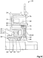
- Fig. 1C is a cross-sectional view of the clutch assembly 20.
- the clutch assembly 20 selectively permits the transfer of torque between a first clutch member, such as (but not limited to) a crankshaft adapter 22 that mounts to an engine crankshaft, and a second clutch member, such as (but not limited to) a pulley 24 deployed in an accessory drive system.
- first clutch member or crankshaft adapter 22 provides the rotational input
- the second clutch member or pulley 24 provides the rotational output such that the clutch assembly 20 selectively permits power to flow from the crankshaft adapter 22 to the pulley 24.
- This clutch assembly 20 is also normally disengaged, i.e., it must be actuated to permit power to flow to the output.
- the pulley 24 includes a sleeve 26 which is supported on the crankshaft adapter 22 by a bearing 28.
- a retainer 30 is rotationally connected to the crankshaft adapter 22.
- the retainer 30 has an aperture 32 (seen best in Fig. 1A ) which holds a wrap spring carrier 34.
- the carrier 34 has a slot 36 which holds a first end 40 of a wrap spring clutch 38.
- An actuator 44 is journalled about the crankshaft adapter 22 via a bushing 46.
- the actuator 44 has a slot 48 which holds a second end 42 of the wrap spring clutch 38.
- the actuator 44 is rotationally connected to an armature 50 such that the two components rotate together yet have some axial play therebetween.
- the axial play is provided by a leaf spring 60 that interconnects the actuator 44 and armature 50 and biases the armature 50 away from the pulley 24. More particularly, (as seen best in Fig. 1A ) the actuator 44 is connected to a rigid backing plate 62 via rivets 64 that pass through apertures 66 and 68 in the leaf spring 60 and backing plate 62, respectively.
- the armature 50 is connected to the leaf spring 60 via a plurality of shank rivets 70 (seen in Fig. 1C ) that pass through tabs 72 (seen best in Figs.
- the leaf spring 60 and backing plate 60 can be omitted and the actuator 44 and armature 50 can be meshingly interconnected via circumferentially disposed teeth on each of the components such as shown in PCT publication WO2013049919 A1 .
- the clutch assembly 20 also includes an electromagnet, comprising wire coil 74 and a magnetically permeable housing 76.
- the electromagnet When energized the electromagnet generates a magnetic flux that flows through the housing 76, the pulley 24 and the armature 50.
- the magnetic flux draws the armature 50 axially, overcoming the bias of the leaf spring 66, so that the armature 50 frictionally engages the pulley 24 at engagement surfaces 80, 82 (referenced in Fig. 1C ).
- the crankshaft adapter 22 which provides the rotational input, carries the retainer 30 and the carrier 34 so that these components (22, 30, 34) rotate at the same speed.
- the wrap spring clutch 38 is connected between the carrier 34 and the actuator 44, as discussed above.
- the wrap spring clutch 38 has a nominal diameter smaller than the inner diameter of the pulley sleeve 26.
- the actuator 44 is rotationally connected to the armature 50, as discussed above. When the electromagnet is de-energized, the armature 50 free-wheels. In this state the second end 42 of the wrap spring clutch 38 is connected to a relatively small inertial mass which is insufficient to cause the wrap spring clutch 38 to expand radially to engage the pulley sleeve 26. Consequently, while the wrap spring clutch 38, actuator 44 and armature 50 all rotate with the crankshaft adapter 22, the retainer 32 and the carrier 34, the wrap spring clutch 38 does not transfer torque to the pulley 24.
- the clutch assembly 20 can include a variety of additional components such as actuator retainer 86 which can be pressed on the crankshaft adapter 22 to prevent the actuator 44 from withdrawing axially away from the pulley 24.
- a slip ring 90 can be provided to aid in contraction of the wrap spring clutch 38 as discussed in WO2013049919A1 .
- the pulley sleeve 26 can have a separate lip member 92 that functions as a grease dam.
- a control system controls the current to the electromagnet and the magnetomotive force it produces.
- the control system includes a printed circuit board (PCB) 95 which utilizes a speed sensor for control and/or diagnostic purposes. More particularly, two Hall effect sensors 96 (one sensor 96a and one sensor 96b, seen best in Fig. 1B ) are mounted on the PCB 95 to detect the passage of teeth 50a formed in the armature 50 and teeth 24a formed in the pulley 24.
- PCB printed circuit board
- control system can be implemented in a variety of ways.
- the control system can control the clutch assembly 20 in an on/off manner such that the wrap spring clutch 38 is either collapsed, in which case no torque is transferred to the pulley 24, or fully expanded, in which case the full torque from the crankshaft adapter 22 is transferred to the pulley 24.
- control system can, by varying the amount of current to the electromagnet, adjust the phase angle between the first and second ends 40, 42 of the wrap spring clutch 38 and thus control the amount of torque transferred to the pulley 24 and consequently the speed of the pulley 24. Examples of such control systems are described and discussed in PCT publication no. WO2013152430 , the contents of which are incorporated herein in their entirety.
- Fig. 2 shows another embodiment of a clutch assembly 120, which is discussed in WO2013152430A1 and WO2013049919A1 .
- the clutch assembly 120 includes a first clutch member provided by a pulley 124 that is engaged with a belt 199 and a second clutch member provided by a shaft adaptor 122 configured for mounting to the shaft 110 of a driven vehicular accessory such as a water pump impeller 197.
- the pulley 124 provides the rotational input and the shaft adaptor 122 provides the rotational output such that the clutch assembly 120 selectively permits power to flow from the pulley 124 to the shaft adaptor 122.
- This clutch assembly 120 is normally engaged, i.e., it must be actuated to stop power flowing to the output.
- the clutch assembly 120 includes a wrap spring clutch 138, an armature 150, an actuator 144 and an electromagnet that includes a wire coil 174 and a housing 176.
- the electromagnet is mounted to a stationary member 198 which may be a bracket that is integral with the housing for the accessory.
- a bearing is shown at 195 between the shaft 110 and the stationary member 198 to support the shaft 110 for rotation thereon.
- Another bearing is shown at 193 between the pulley 124 and the stationary member 198 to support the pulley 124 for rotation thereon.
- the wrap spring clutch 138 is similar to the wrap spring clutch 38 except that the nominal diameter of the wrap spring clutch 138 is sufficiently large to bring its coils into engagement with an inner surface 139 of the shaft adaptor 122 so that the clutch assembly is normally engaged.
- the electromagnet generates a magnetic flux which passes through the armature 150 and draws it into engagement with a stationary friction surface 137, which functions as a relatively large inertial mass. This engagement, in turn, shifts the angular position of the second end of the wrap spring clutch 138 relative to its first end, causing the wrap spring clutch 138 to contract radially away from the inner surface 139.
- the wrap spring clutch 138 By applying sufficient current to the electromagnet coil 174 the wrap spring clutch 138 can be contracted completely out of engagement with the clutch surface 139 so that no torque is transferred to the shaft adapter 122. By applying some lesser amount of current to the electromagnet coil 174, the wrap spring clutch 138 can transmit some torque to the shaft adapter 122 and thus vary the output speed of the shaft 110 relative to that of the pulley 124.
- a control system can be implemented to control the clutch assembly 120 in either an on/off manner or a variable speed manner.
- the output second clutch member rotates at the same speed as the armature and thus the armature speed can provide useful control and/or diagnostic information.
- the armature speed can provide a feedback signal to the controller.
- the armature speed can provide diagnostic information, e.g., confirming that the device is working.
- the armature speed can be measured by a conventional speed sensor such as the Hall effect sensors 96 of clutch assembly 20 which are used to sense the passage of armature teeth 50a.
- a conventional speed sensor such as the Hall effect sensors 96 of clutch assembly 20 which are used to sense the passage of armature teeth 50a.
- such an additional sensor adds cost and presents another mode of failure.
- the discussion that follows presents another technique for sensing the armature speed using the principles of electromagnetic induction, which eliminates the need for an additional sensor.
- Figs. 3A and 3B show another embodiment of an armature 200 and an electromagnet 210 which can be used in clutch assemblies 20, 120.
- the electromagnet 210 includes a housing 212 which houses a wire coil 215.
- the armature 200 has a circumferential wall with an actuator engagement side 202 and a speed sensing side 204.
- the actuator engagement side 202 has a plurality of teeth 206 for rotationally connecting the armature 200 to meshing teeth formed in the actuator (not shown).
- the actuator engagement side 202 could embody other means for interconnecting the armature 200 to the actuator, such as the leaf spring interconnect shown in Figs. 1A - 1C in which case the actuator engagement side could be smooth or toothless.
- the speed sensing side 204 of the armature 200 has a plurality of axially extending teeth 208 and corresponding cutouts 209 formed therein.
- the electromagnet housing 212 has an inner circumferential wall with a plurality of axially extending teeth 214 and corresponding cutouts 216 formed therein.
- the width W of each of the armature and housing teeth and cutouts 208, 214 is substantially the same but may differ in other embodiments.
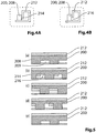
- the armature teeth 208 and the housing teeth 214 are juxtaposed circumferentially so as to provide a mechanism for varying the magnetic reluctance of the armature 200 as it rotates relative to the housing 210.
- the position of the armature teeth 208 shift relative to the housing teeth 214, reducing the effective area as seen in Fig. 5(b) .
- the effective area reaches its minimum value when the armature teeth 208 directly face or oppose the housing cutouts 216, as seen in Fig. 4B and Fig. 5(c) .
- the value of the effective area changes it direction and starts to increase again as the armature 200 continues to rotate, as seen in Fig. 5(d) , and reaches its starting position where the effective area is again at its maximum value as seen in Fig. 4A and Fig. 5(e) (which is the same as Fig. 5(a) ).
- This cyclical increase and decrease in the effective area of the magnetic path causes the magnetic reluctance and flux to cyclically increase and decrease so as to induce a cyclically varying voltage on the electromagnet, which can be sensed as a fluctuating coil current.
- V f ( d ⁇ / dt )
- V the induced voltage
- ⁇ the magnetic flux.
- the speed of the armature 200, and hence the second clutch member can be measured.
- the speed will be proportional to the number of armature teeth 208 measured in a given time period.
- the upper graph of Fig. 6 shows an example of a coil current in an on/off controlled, normally engaged clutch assembly such as assembly 120.
- the lower graph of Fig. 6 illustrates the corresponding speed 238 of the output second clutch member (e.g., impeller).
- the control system generates two current levels: an activation current level 230, which is sufficient to fully collapse the wrap spring clutch and inhibit torque transfer to the second clutch member, and an excitation current level 234, which has no discernible effect on collapsing the wrap spring clutch but generates sufficient flux to induce and measure the fluctuating speed sensing current caused by the varying reluctance of the armature 200.
- the excitation current 234 may be in the range of 70 to 120 mA but the level will differ depending on the particular application.
- the activation current 230 may be applied and adjusted to control the amount of torque transfer to the second clutch member and therefore to control the speed of the second clutch member. Any suitable control scheme may be used to controlling the speed of the second clutch member. For example, a control scheme as described in pages 32-41 and shown in Figures 12a-14b of PCT patent publication WO2014165977A1 .
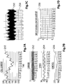
- Figs. 7A- 7D shows an example of a coil current 250 in a variable speed, normally engaged clutch assembly such as assembly 20.
- the coil current 250 can be decomposed into three components: a carrier current 252, representing a pulse width modulation signal that fluctuates at the switching frequency; a control current 256 for controlling the speed of the output second clutch member; and a speed sensing current 254 caused by the varying reluctance of the armature 200.
- Fig. 7C shows an oscilloscope trace of the coil current 250 (in a narrow time window relative to Fig. 7A), and Fig. 7D shows a digital speed signal 258 derived from processing the speed sensing current 254, as next discussed.
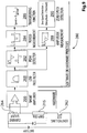
- Fig. 8 shows one embodiment of processing logic 260 for deriving the digital speed signal 258 and determining the armature speed.
- the control system can include a controlling switch such as a FET 262 to apply the activation current 230 to the coil 215 using pulse width modulation (PWM) techniques.
- PWM pulse width modulation
- the same switch an also be used to apply the low level excitation current 234 using a low duty cycle PWM drive.
- the coil 215 is connected in series to a suitably sized resistor 264 which functions as a current shunt or any other suitable current measurement sensor.
- An amplifier 266 amplifies the sensed current which is then filtered by a bandpass filter 268 to remove high and low frequency components.
- a zero crossing detector 270 converts the filtered sinusoidal signal to the digital speed signal 258. From this, the period of the digital speed signal 258 can be easily measured and the armature speed calculated at logic blocks 272, 274. The armature speed is calculable in revolutions per minute (rpm) as 60/(period*number of teeth).
- the bandpass filter may be omitted and an alternative means for removing d.c. signal from the sensed current may be provided, such as an a.c. coupling.
- the amplifier may also be omitted depending on the particular application.
- the processing logic 260 can be implemented in hardware as shown in Figure 10 or in software using a digital signal processor (DSP), in which an analog to digital converter (ADC) (not shown) can be employed to process the amplified current to a logic signal for use by the DSP.
- DSP digital signal processor
- ADC analog to digital converter
- Fig. 9 shows another embodiment of processing logic 280 for deriving the digital speed signal 258 and determining the armature speed.
- the amplified sensed current is also filtered by a bandpass filter 268 to remove high and low frequency components.
- a peak detector 282 converts the filtered sinusoidal signal to a peak timing signal. From this, the frequency or period of peak timings can be measured and the armature speed calculated at blocks 284, 286.
- This embodiment also includes a parallel noise filtering branch which measures the amplitude of the filtered signal at block 288 and determines zero speed or stoppage at block 280 if the amplitude of the amplified signal is less than a predetermined threshold value.
- the bandpass filter may be omitted and an alternative means for removing d.c. signal from the sensed current may be provided, such as an a.c. coupling.
- the amplifier may also be omitted depending on the particular application.
- the processing logic 280 can be implemented in hardware as shown in Fig. 11 or in software using a DSP, in which case an ADC (not shown) can be employed to process the amplified current to a digital signal for use by the DSP.
- an ADC (not shown) can be employed to process the amplified current to a digital signal for use by the DSP.
- Figs. 12A and 12B show an alternative embodiment of an armature 200' and electromagnet 210' which can be used in clutch assemblies 20, 120.
- This embodiment has double the number of armature teeth 208 and housing teeth 214 as compared to the embodiment shown in Figs 3A and 3B .
- Figs. 13A and 13B show another alternative embodiment of an armature 200" which has non-ferrite (e.g., plastic) molded inserts 300 fitted into the armature cutouts 209 on the speed sensing side 204.
- This construction enables the armature 200, 200' to have a smooth or contiguous form on the speed sensing side 204. It was found that the non-contiguous or open form of the armature had a tendency to displace lubricant that is typically present in the clutch assembly. The open form scooped and displaced lubricant in a manner that tended to propel the armature away from the base of the electromagnet housing 212 in axial and radial directions, resulting in noise, vibration and rattling issues.
- non-ferrite e.g., plastic
- the open form armature had a reduced clamping force, which affected the contraction or expansion of the wrap spring clutch.
- the contiguous or closed form of the armature with non-ferrite inserts 300 reduces or eliminates these issues without affecting the ability to vary the magnetic reluctance of the rotating armature 200, 200'.
- the inserts 300 can be installed through an over-molding process as known in the art.
- the non-ferrite inserts 300 can optionally be provided in the form of a toothed ring (not shown) that has a thin web interconnecting the non-ferrite teeth/inserts and the ring adhered or press-fit into place.
- the armature and electromagnet housing teeth and cutouts may be rectangular shaped (along a circumferential line), it should be appreciated that the teeth and cutouts may have other geometric forms such as trapezoidal, triangular, or elliptical and still provide a measurable varying reluctance for sensing the speed of the rotating armature within the electromagnet.
- the electromagnet housing does not necessarily have to have teeth. A similar effect can be achieved by changing the shape of the electromagnet housing and/or electromagnet coil.
- the housing and coil may be formed in the shape of an ellipse to thereby yield two positions of maximum reluctance and two positions of minimum reluctance as the armature rotates.
- the electromagnet housing and/or electromagnet coil can be formed in the shape of a square to yield four positions of maximum reluctance and four positions of minimum reluctance as the armature rotates.
- the speed sensing application discussed in detail above related to an armature which functions as an axially moving pole piece in a clutch assembly
- the invention is not limited to this application.
- the speed sensing technique can be applied to a non-axially moving magnetically permeable rotor that spins in situ in any electromechanical apparatus which has a drive (electrical or mechanical) for rotating the rotor relative to an electromagnet, so long as the rotor is in the magnetic path of and is influenced by the electromagnet.
- the speed sensing technique discussed herein may be applied to a rotating machine such as a motor that has a rotating output shaft.
- the output shaft could have a rotor similar in shape to armature 200 mounted thereon, with the rotor spinning within the confines of an electromagnet similar to cylindrical electromagnet 210.
- circuitry can apply an excitation level current to the electromagnet coil, sense the coil current, and process the resulting fluctuating speed sensing current to determine the speed of the motor based on the frequency of the fluctuations.
- FIG 14 is a schematic view of a typical engine coolant loop.
- the engine is shown at 300
- a temperature sensor is shown at 302 which measures the temperature of coolant leaving the engine 300.
- the water pump is shown at 304 and may be any suitable type of water pump such as a clutched water pump that can be turned on and off as desired. Examples of such pumps are described in PCT publication WO2012000089A1 , the contents of which are incorporated herein in their entirety.
- a thermostat is shown at 306 and a radiator is shown at 308.
- a radiator bypass line is shown at 310 and may be used to direct heated coolant to a heat exchanger to heat the vehicle's cabin.
- a control system 314 ( Figure 14 ) may be provided which controls the operation of the water pump 304 and which receives signals from the temperature sensor 302.
- the control system 314 may be a standalone unit that is separate from the Engine Control Unit, or it may be part of the vehicle's ECU, or it may be partially integrated into the ECU while also including a separate standalone unit for carrying out some functions.
- the locations of the components relative to each other in the coolant loop may differ.
- Figure 15 represents the coolant temperature on the engine 300 where the water pump 304 is performing adequately, wherein the coolant temperature is measured via the temperature sensor 302.
- the water pump 304 may be operated in a fully-on mode for a short initial period so as to 'stir' the coolant, thereby helping to ensure that the temperature sensor obtains a more-accurate reading of the overall coolant temperature.
- the curve representing the coolant temperature is shown at 320.
- a curve representing the state of the water pump 304 is shown at 322.
- T1 the water pump 304 is on.
- the temperature of the coolant begins to rise as the engine 300 warms up.
- a selected point in time (e.g.
- the control system 314 may shut off the water pump 304. At this point flow through the coolant loop stops and the dominant form of heat transfer from the engine 300 to the coolant is conduction. As a result, the temperature of the coolant in the immediate vicinity of temperature sensor 304 may remain substantially static briefly resulting in a 'flat-line' region (shown at 326) in the curve 320, as shown in time period T2. While it is described as a flat-line region 326 it will be understood that this region 326 is not necessary strictly flat (i.e. having a strictly zero slope throughout) but is a region having a substantially zero average slope, or a slope that is substantially more flat (i.e. more towards zero) than the average slope of the curve 320 in the first time period T1.
- the control system 314 may wait a first selected period of time (e.g. a few seconds) to let the coolant flow stop and for the coolant temperature at the sensor 302 to stabilize before determining that time period T2 has begun.
- the number of seconds to wait before starting time period T2 may be selected based on parameters such as the temperature sensor properties (e.g. its associated time constant), the distance between the sensor 302 and the engine 300 and other parameters such as engine load, ambient temperature, so that the temperature would have leveled off somewhat at least when the water pump 304 is operating properly.
- the control system 314 need only permit time period T2 to last for a selected amount of time such as 20 to 25 seconds.
- time period T2 were permitted to last for a very long time, heat transfer from the engine through the coolant (and possibly passive convective flow of the coolant) could eventually cause a rise in the temperature seen by sensor 302 even though the water pump 304 was off during this time period.
- the control system 314 may then operate water pump 304 in another operating regime where the pump 304 is cycled on and off briefly in order to generate some coolant flow between the engine 300 and the temperature sensor 302 and through the coolant loop.
- the time period in which this operating regime takes place is shown as time period T3.
- This cycling is seen in the curve 322 as the brief 'on' periods shown at 328.
- the temperature sensor 304 will again pick up an increase in coolant temperature as the heated coolant from the engine 300 is periodically circulated a bit.
- the temperature increases seen by the sensor 302 may be somewhat stepped as slugs of coolant from within the engine 300 are transported to the sensor when the pump 304 is periodically turned on.
- the temperature determined by the control system 314 is an average over a selected number of seconds, or in embodiments where the signal sent by the sensor 302 is an average over a selected number of seconds (i.e. based on its time constant)
- the curve 320 may be seen to rise relatively smoothly in time period T3 as the averaging effect smooth out the temperature fluctuations from the periodic slugs of coolant that are moved past the sensor 302.
- the presence of a detectable flat-line region 326 in the temperature curve 320 during time period T2, and the overall shape of the curve 320 as shown in Figure 15 during time periods T1 and T2 particularly, depends on the temperature of the coolant being sufficiently low that the thermostat 306 does not open and direct coolant through the radiator 308 during these two time periods. If the thermostat opens during these time first two periods, it can be more difficult to use the present method to determine whether the water pump 304 is operating well. As a result, if the control system 314 detects that the temperature of the coolant as obtained from the signals from sensor 302 is too high (e.g. above 60 degrees C) the method can be abandoned so as to not to risk determining false positives or false negatives in the health of the pump operation. The control system 314 could then wait to initiate the method during a subsequent event in which the engine 300 is cold-started, again monitoring the coolant temperature to determine whether the temperature is sufficiently low throughout time periods T1 and T2.
- the presence of the detectable flat-line region 326 in the curve 320 during time period T2 indicates likely proper functioning of the water pump 304. If the pump 304 is stuck on or stuck off, the curve 320 will appear differently and will lack a detectable flat-line region 326.
- Figure 16 shows a situation where the water pump 304 is stuck on (i.e. the water pump 304 does not shut off even when commanded to), so as to illustrate what the control system 314 may find if there is a problem with the water pump 304.
- T1 the water pump 304 is on and the control system 314 does not check for a flat-line region at this time.
- the control system 314 determines that the coolant temperature has risen sufficiently, the control system 314 shuts off the water pump 304 and determines whether a flat-line region exists is time period T2.
- the control system 314 can notify the appropriate program section of the vehicle's ECU and/or the vehicle driver, that there is a problem in the operation of the water pump 304.
- Figure 17 shows a situation where the water pump 304 is stuck off and therefore does not turn off even when commanded to.
- T1 when the water pump 304 would normally be on, the temperature climbs very slowly due to the lack of circulation of coolant through the engine 300 and to the sensor 302 (because the water pump 30 is in fact off).
- the water pump 304 remains off and the temperature continues to climb as heat from the engine 300 migrates through the coolant to the sensor 302.
- T2 there is no flat-line region to the temperature curve 320.
- the control system 314 can notify the appropriate program section of the vehicle's ECU and/or the vehicle driver that there is a problem with the water pump or with the coolant system in general.
- Figure 18 illustrates an example of how the method may be carried out by the control system 314 ( Figure 14 ).
- the method is shown in Figure 18 at 350.
- the control system 314 determines whether the coolant temperature is too high which represents a risk that the thermostat 306 will open during time period T1 or T2. If the temperature is too high, then the method ends at step 364. If the temperature is not too high, then at step 352 the control system 314 determines a first temperature (called CT1) at a first point in time during the second time period T2 (e.g. immediately at the beginning of time period T2, which is a first selected period of time after the command was issued to stop the water pump 304).
- CT1 first temperature
- the control system determines a second temperature (called CT2) a second point in time which is after a second selected period of time has passed since the command was issued to stop the pump 304. This second point in time denotes the end of time period T2.
- CT2 a second temperature
- the control system 314 takes a difference between CT2 and CT1 and at step 358 it determines whether the difference is larger than a predetermined threshold flat-line value so as to determine whether or not a flat-line region exists. If the difference is larger than the predetermined threshold flat-line value then the control system 314 may output an indication that a problem may exist with the water pump 304 at step 360. If the difference is not larger than the predetermined threshold flat-line value, then the control system 314 may do nothing or may output an indication that the water pump 304 appears to be operating well at step 362.
- Testing of a sample engine during vehicle design and development may be used to determine parameters such as the temperature threshold values below which the coolant temperature much be in order to permit the control system 314 to check for a flat-line region, the parameter or parameters that signal the end of time period T1 and the start of time period T2, the length of time period T2, and other parameters.
- An advantage to using the method described in Figures 15-18 is that it can be carried out using sensing components that already form part of most new vehicles today.
- the temperature sensor 302 is typically provided on new vehicles so as to monitor the temperature of the coolant.
- the method 350 may be implemented relatively easily and inexpensively without the need for specialized sensors such as sensors to measure the speed of the water pump 304, sensors installed in the engine block to measure the metal temperature, and the like.
- FIG 400 Another method for determining whether the water pump 304 is operating properly is shown at 400 in Figure 19 with reference to the graph in Figure 20 .
- the method in general checks to see if a dip in the coolant temperature follows a sufficiently high change in the commanded duty cycle of the pump 304, and is therefore applicable in embodiments wherein the pump 304 is clutched and can be turned on and off.
- Such pumps may be operated by continuously clutching and declutching them according to a selected duty cycle. This permits the flow rate of the pump 304 to be selectable throughout a range. If a relatively high increase in the duty cycle of the pump 304 is commanded, it is expected that, if the pump 304 is operating properly, there should be a commensurate dip in the coolant temperature shortly thereafter. If the pump 304 is not operating properly (e.g. if the pump 304 is stuck on, or is stuck off), then the control system 314 will not see the expected dip in the coolant temperature.
- the method 400 begins by verifying at step 402 whether the criteria are met to see whether it is appropriate to check for a dip in the coolant temperature. These criteria may include:
- the method proceeds to check for a sufficiently large dip in the coolant temperature.
- the control system 314 may check if the change in the duty cycle of the pump 304 is greater than 50%, however, any other suitable value that is determined to work well may be used.
- the control system 314 may, for example, check if the pump 304 has been operating at less than 25% for at least 20 seconds, however any other suitable maximum duty cycle and minimum time period may be used.
- the threshold values used for the criteria above may be determined by testing the engine during design and development of the vehicle.
- steps 404, 406 and 408 are carried out.
- the control system 314 searches for a peak temperature (TP) in the coolant temperature over a selected first time period T1 after the increase in the duty cycle occurs.
- the selected time period may be, for example, 5 seconds.
- the control system 314 searches for a minimum coolant temperature (TM) over a selected second time period T2 that is immediately after the first time period T1.
- the second time period T2 may be, for example, 20 seconds.
- the control system 314 determines a difference ( ⁇ T) between the peak temperature TP and the minimum temperature TM.
- the control system 314 determines whether the difference ⁇ T is larger than a selected threshold value.
- control system 314 determines that a dip in the temperature has been found and the control system records the event by incrementing a dip counter at step 412. Also a total dip check counter is incremented for every time a dip check is carried out and so would be incremented in step 412. If the difference ⁇ T determined at step 410 is not larger than the relevant threshold value then the control system 314 notes at step 414 that a dip was not found even though one was expected based on the aforementioned criteria having been met, e.g. by incrementing the total dip check counter but not incrementing the dip counter.
- control system 314 After either of steps 412 and 414 the control system 314 sends program control to step 416.
- the control system 314 may check if the water pump 304 is still being driven in a partial flow mode (i.e. if it is being clutched and declutched in order to achieve some selected flow rate that is less than its maximum flow rate) and checks if the engine is still on. If so, then control returns to step 402 wherein the criteria described above are checked. If the engine is off or the pump 304 is no longer being used, the control system 314 may determine that the drive cycle is now completed, and it checks at step 418 to see if the ratio of dip counts (i.e.
- step 420 is carried out where the control system 314 checks whether the ratio is less than the selected value, in which case, the dip check determines that there may be problem with the pump 304 and may at step 421 output an indication of the possible problem (e.g. to a suitable element in the ECU, and/or to the vehicle driver). If the ratio is neither greater than nor less than the selected value, then the control system 314 may determine that the results were indeterminate. The method ends at 422.
- the curves shown at 450 and 460 in Figure 20 illustrate the execution of the method 400.
- the curves 450 and 460 are representative of the temperature and water pump duty cycle respectively in an example drive cycle for a vehicle.
- a first event shown at E1 occurs at about 380 seconds into the drive cycle, and the peak and subsequent minimum temperatures are recorded and the difference between them (shown as ⁇ T1) recorded over the subsequent first and second time periods (together shown as ⁇ t).
- a second event is shown at E2 with a resulting temperature difference ⁇ T2 and a third event at E3 with a resulting temperature difference ⁇ T3.
- the coolant temperature is expected to drop from whatever its current temperature is to approximately the opening temperature of the thermostat.
- the thermostat is what is referred to as a 'smart' thermostat
- the opening temperature may change depending on certain parameters, thereby making it more difficult for the control system 314 to determine if a suitably sized temperature difference occurred.
- the method 400 it is preferred for the method 400 to be carried out with a standard thermostat that has a constant opening temperature. It is contemplated that the control system 314 could be programmed to compensate for a changing opening temperature however, when determining whether the temperature difference is sufficiently large to count as a dip count.
- two different methods may be used to determine the health of the water pump 304.
- two methods that are usable under different conditions of a drive cycle, it is more likely that at least one of these methods will be usable during any given drive cycle so as to identify a faulty pump 304 as quickly as possible.
- a cooling system for a vehicle that includes a water pump configured to circulate coolant through an engine, wherein the water pump is selectably clutched so as to permit the water pump to be turned on and off, a temperature sensor positioned to sense the temperature of the coolant, and a control system, wherein the control system (e.g.
- control system 314) is programmed with two schemes for detecting the health of the water pump 304, the first scheme (e.g. method 350) is carried out by the control system if a first set of criteria are met during operation of the vehicle (e.g. whether the coolant temperature is too high during time period T1, whether the temperature sensed by the sensor 302 has risen by a selected amount during time period T1).
- the second scheme is carried out by the control system if a second set of criteria are met during operation of the vehicle (e.g. the four criteria listed above, which are checked in step 402). As can be seen the second set of criteria are different than the first set of criteria.
- the first scheme may be summarized as follows:
- the second scheme may be summarized as follows:
Landscapes
- Engineering & Computer Science (AREA)
- General Engineering & Computer Science (AREA)
- Mechanical Engineering (AREA)
- Chemical & Material Sciences (AREA)
- Combustion & Propulsion (AREA)
- Physics & Mathematics (AREA)
- Power Engineering (AREA)
- Electromagnetism (AREA)
- Microelectronics & Electronic Packaging (AREA)
- General Physics & Mathematics (AREA)
- Fluid Mechanics (AREA)
- Hydraulic Clutches, Magnetic Clutches, Fluid Clutches, And Fluid Joints (AREA)
Description
- This disclosure relates generally to electromechanical apparatuses and more particularly to water pumps that are clutched and which are used to circulate coolant through an engine.
-
US 4 874 072 A discloses a clutch. This clutch is provided with a variable reluctance sensor being a separate element from the clutch. Variable reluctance sensors used as rotatable speed sensors are, for example, known fromUS 2013/187638 A1 .WO 2013/152430 A1 ,WO 2012/045151 A1 ,WO 2012/079155 A1 ,WO 2013/155615 A1 WO 2012/131663 A1 disclose spring clutches. - Some vehicles have water pumps that are belt driven but are clutched so as to permit the impeller of the water pump to be turned on and turned off. In some more advanced proposed united, the clutch may be cycled on and off repeatedly according to an adjustable duty cycle, permitting the water pump to achieve a range of selected flow rates for the coolant in the vehicle's coolant system. While such proposed units are advantageous it would be beneficial to be able to determine if there is a breakdown in the water pump that causes is to be non-operational (e.g. not pumping at all), or that causes it to be stuck at full flow. Furthermore, it would be beneficial to be able to determine the speed of the water pump when it is operating. Preferably one or more of these features can be provided at relatively low cost.
- The present invention provides a clutch assembly having the features defined in
claim 1. Further preferred embodiments are defined in dependent claims 2 to 10. Moreover, it is provided a method for detecting a speed of a magnetic permeable rotor having the features defined in claim 11. Further preferred embodiments are defined independent claims 12 to 14. - The foregoing and other aspects of the disclosure will be more readily appreciated by reference to the accompanying drawings, wherein:
-
Figures 1A and1B are exploded perspective views of a clutch assembly for use in a device on a vehicle engine; this clutch assembly, shown inFig 1A andB is helpful for understanding the present invention. -
Figure 1C is a magnified sectional elevation view of a portion of the clutched device shown inFigures 1A and1B ; -
Figure 2 is a sectional elevation view of a clutched device; -
Figures 3A and 3B are perspective views of an electromechanical apparatus that is usable with the clutch assemblies shown inFigures 1A ,1B and 2 ; -
Figures 4A and 4B are sectional views of an armature and an electromagnet housing that houses an electromagnet coil, which are part of the electromechanical apparatus shown inFigures 3A and 3B ; -
Figures 5(a)-5(e) are sectional views of the armature and electromagnet housing at different relative positions; -
Figure 6 is a graph illustrating current in the electromagnet coil and the speed of selected clutched components over a period of time; -
Figures 7A-7C are graphs illustrating the current in the electromagnet coil; -
Figure 7D is a graph illustrating an output from a speed measurement circuit for determining the speed of the electromechanical apparatus; -
Figure 8 is a block diagram illustrating a control scheme that is usable to carry out speed measurement on an armature of the electromechanical apparatus; -
Figure 9 is a block diagram illustrating an alternative control scheme that is usable to carry out speed measurement on an armature of the electromechanical apparatus; -
Figure 10 illustrate a circuit configured to be used to carry out the control scheme illustrated inFigure 8 ; -
Figure 11 and Figures 11A - 11E illustrate a circuit configured to be used to carry out the control scheme illustrated inFigure 9 ; -
Figures 12A and 12B are exploded and non-exploded perspective views of another embodiment of an electromechanical apparatus; -
Figures 13A and 13B are exploded and non-exploded perspective views of yet another embodiment of an electromechanical apparatus; -
Figure 14 is a schematic illustration of a coolant system in a vehicle; -
Figure 15 is a graph illustrating the coolant temperature and duty cycle for a properly-functioning water pump from the coolant system shown inFigure 14 ; -
Figure 16 is a graph illustrating the coolant temperature and duty cycle for a water pump that is stuck on; -
Figure 17 is a graph illustrating the coolant temperature and duty cycle for a water pump that is stuck off; -
Figure 18 is a flow diagram illustrating a method of determining whether the water pump shown inFigure 14 is operating properly; -
Figure 19 is a flow diagram illustrating another method of determining whether the water pump shown inFigure 14 is operating properly; and -
Figure 20 is a graph illustrating the use of the method shown inFigure 19 . -
Figures 1A and1B are exploded views of a portion of aclutch assembly 20.Fig. 1C is a cross-sectional view of theclutch assembly 20. Theclutch assembly 20 selectively permits the transfer of torque between a first clutch member, such as (but not limited to) acrankshaft adapter 22 that mounts to an engine crankshaft, and a second clutch member, such as (but not limited to) apulley 24 deployed in an accessory drive system. In this assembly the first clutch member orcrankshaft adapter 22 provides the rotational input and the second clutch member orpulley 24 provides the rotational output such that theclutch assembly 20 selectively permits power to flow from thecrankshaft adapter 22 to thepulley 24. Thisclutch assembly 20 is also normally disengaged, i.e., it must be actuated to permit power to flow to the output. - Referring to
Figures 1A - 1C , thepulley 24 includes asleeve 26 which is supported on thecrankshaft adapter 22 by abearing 28. Aretainer 30 is rotationally connected to thecrankshaft adapter 22. Theretainer 30 has an aperture 32 (seen best inFig. 1A ) which holds awrap spring carrier 34. Thecarrier 34 has a slot 36 which holds afirst end 40 of awrap spring clutch 38. Anactuator 44 is journalled about thecrankshaft adapter 22 via abushing 46. Theactuator 44 has a slot 48 which holds asecond end 42 of thewrap spring clutch 38. - The
actuator 44 is rotationally connected to anarmature 50 such that the two components rotate together yet have some axial play therebetween. In the illustrated embodiment the axial play is provided by aleaf spring 60 that interconnects theactuator 44 andarmature 50 and biases thearmature 50 away from thepulley 24. More particularly, (as seen best inFig. 1A ) theactuator 44 is connected to arigid backing plate 62 via rivets 64 that pass throughapertures leaf spring 60 andbacking plate 62, respectively. Thearmature 50 is connected to theleaf spring 60 via a plurality of shank rivets 70 (seen inFig. 1C ) that pass through tabs 72 (seen best inFigs. 1A and1C ) on thearmature 50. In other embodiments, theleaf spring 60 andbacking plate 60 can be omitted and theactuator 44 andarmature 50 can be meshingly interconnected via circumferentially disposed teeth on each of the components such as shown inPCT publication WO2013049919 A1 - The
clutch assembly 20 also includes an electromagnet, comprisingwire coil 74 and a magneticallypermeable housing 76. - When energized the electromagnet generates a magnetic flux that flows through the
housing 76, thepulley 24 and thearmature 50. The magnetic flux draws thearmature 50 axially, overcoming the bias of theleaf spring 66, so that thearmature 50 frictionally engages thepulley 24 at engagement surfaces 80, 82 (referenced inFig. 1C ). - The
crankshaft adapter 22, which provides the rotational input, carries theretainer 30 and thecarrier 34 so that these components (22, 30, 34) rotate at the same speed. Thewrap spring clutch 38 is connected between thecarrier 34 and theactuator 44, as discussed above. Thewrap spring clutch 38 has a nominal diameter smaller than the inner diameter of thepulley sleeve 26. Theactuator 44 is rotationally connected to thearmature 50, as discussed above. When the electromagnet is de-energized, thearmature 50 free-wheels. In this state thesecond end 42 of thewrap spring clutch 38 is connected to a relatively small inertial mass which is insufficient to cause thewrap spring clutch 38 to expand radially to engage thepulley sleeve 26. Consequently, while thewrap spring clutch 38,actuator 44 andarmature 50 all rotate with thecrankshaft adapter 22, theretainer 32 and thecarrier 34, thewrap spring clutch 38 does not transfer torque to thepulley 24. - However, when the electromagnet is energized the magnetic flux draws the
armature 50 axially to frictionally engage thepulley 24 via engagement surfaces 80, 82, thus connecting thesecond end 42 of thewrap spring clutch 38 to a relatively large inertial mass. This causes a lag in the phase angle between thearmature 50 and thecrankshaft adapter 22 and causes thewrap spring clutch 38 expands radially to transfer torque to thepulley 24. - The
clutch assembly 20 can include a variety of additional components such asactuator retainer 86 which can be pressed on thecrankshaft adapter 22 to prevent the actuator 44 from withdrawing axially away from thepulley 24. Aslip ring 90 can be provided to aid in contraction of thewrap spring clutch 38 as discussed inWO2013049919A1 . Thepulley sleeve 26 can have aseparate lip member 92 that functions as a grease dam. - A control system controls the current to the electromagnet and the magnetomotive force it produces. In the illustrated embodiment the control system includes a printed circuit board (PCB) 95 which utilizes a speed sensor for control and/or diagnostic purposes. More particularly, two Hall effect sensors 96 (one
sensor 96a and onesensor 96b, seen best inFig. 1B ) are mounted on thePCB 95 to detect the passage ofteeth 50a formed in thearmature 50 andteeth 24a formed in thepulley 24. - The control system can be implemented in a variety of ways. In one implementation the control system can control the
clutch assembly 20 in an on/off manner such that thewrap spring clutch 38 is either collapsed, in which case no torque is transferred to thepulley 24, or fully expanded, in which case the full torque from thecrankshaft adapter 22 is transferred to thepulley 24. In another implementation the control system can, by varying the amount of current to the electromagnet, adjust the phase angle between the first and second ends 40, 42 of thewrap spring clutch 38 and thus control the amount of torque transferred to thepulley 24 and consequently the speed of thepulley 24. Examples of such control systems are described and discussed inPCT publication no. WO2013152430 , the contents of which are incorporated herein in their entirety. -
Fig. 2 shows another embodiment of aclutch assembly 120, which is discussed inWO2013152430A1 andWO2013049919A1 . Theclutch assembly 120 includes a first clutch member provided by apulley 124 that is engaged with abelt 199 and a second clutch member provided by ashaft adaptor 122 configured for mounting to theshaft 110 of a driven vehicular accessory such as awater pump impeller 197. In thisassembly 120 thepulley 124 provides the rotational input and theshaft adaptor 122 provides the rotational output such that theclutch assembly 120 selectively permits power to flow from thepulley 124 to theshaft adaptor 122. Thisclutch assembly 120 is normally engaged, i.e., it must be actuated to stop power flowing to the output. - The
clutch assembly 120 includes awrap spring clutch 138, anarmature 150, anactuator 144 and an electromagnet that includes awire coil 174 and ahousing 176. The electromagnet is mounted to astationary member 198 which may be a bracket that is integral with the housing for the accessory. A bearing is shown at 195 between theshaft 110 and thestationary member 198 to support theshaft 110 for rotation thereon. Another bearing is shown at 193 between thepulley 124 and thestationary member 198 to support thepulley 124 for rotation thereon. - The
wrap spring clutch 138 is similar to thewrap spring clutch 38 except that the nominal diameter of thewrap spring clutch 138 is sufficiently large to bring its coils into engagement with aninner surface 139 of theshaft adaptor 122 so that the clutch assembly is normally engaged. The electromagnet generates a magnetic flux which passes through thearmature 150 and draws it into engagement with astationary friction surface 137, which functions as a relatively large inertial mass. This engagement, in turn, shifts the angular position of the second end of thewrap spring clutch 138 relative to its first end, causing thewrap spring clutch 138 to contract radially away from theinner surface 139. By applying sufficient current to theelectromagnet coil 174 thewrap spring clutch 138 can be contracted completely out of engagement with theclutch surface 139 so that no torque is transferred to theshaft adapter 122. By applying some lesser amount of current to theelectromagnet coil 174, thewrap spring clutch 138 can transmit some torque to theshaft adapter 122 and thus vary the output speed of theshaft 110 relative to that of thepulley 124. - As discussed above, a control system can be implemented to control the
clutch assembly 120 in either an on/off manner or a variable speed manner. - In each of the foregoing
assemblies Hall effect sensors 96 ofclutch assembly 20 which are used to sense the passage ofarmature teeth 50a. However, such an additional sensor adds cost and presents another mode of failure. The discussion that follows presents another technique for sensing the armature speed using the principles of electromagnetic induction, which eliminates the need for an additional sensor. -
Figs. 3A and 3B show another embodiment of anarmature 200 and anelectromagnet 210 which can be used inclutch assemblies electromagnet 210 includes ahousing 212 which houses awire coil 215. Thearmature 200 has a circumferential wall with anactuator engagement side 202 and aspeed sensing side 204. Theactuator engagement side 202 has a plurality ofteeth 206 for rotationally connecting thearmature 200 to meshing teeth formed in the actuator (not shown). Theactuator engagement side 202 could embody other means for interconnecting thearmature 200 to the actuator, such as the leaf spring interconnect shown inFigs. 1A - 1C in which case the actuator engagement side could be smooth or toothless. - The
speed sensing side 204 of thearmature 200 has a plurality of axially extendingteeth 208 andcorresponding cutouts 209 formed therein. Likewise, theelectromagnet housing 212 has an inner circumferential wall with a plurality of axially extendingteeth 214 andcorresponding cutouts 216 formed therein. In the illustrated embodiment the width W of each of the armature and housing teeth andcutouts armature teeth 208 and thehousing teeth 214 are juxtaposed circumferentially so as to provide a mechanism for varying the magnetic reluctance of thearmature 200 as it rotates relative to thehousing 210. - The phenomenon is explained in greater detail with reference to the schematic diagrams of
Figs. 4A and 4B (in cross-sectional view) andFig. 5 (in plan view). As thearmature 200 rotates relative to thehousing 210 the total cross-sectional area between thecoil 215 and thearmature 200, which represents the effective area of the magnetic path, cyclically increases and decreases as thearmature teeth 208 andhousing teeth 214 cyclically face and pass one another. More particularly, the effective area reaches its maximum value when the armature andhousing teeth 208, 214 (as well as armature andhousing cutouts 209, 216) directly face one another or are in registration as seen inFig. 4A and Fig. 5(a) . As thearmature 200 continues to rotate (to the left inFig. 5 ) the position of thearmature teeth 208 shift relative to thehousing teeth 214, reducing the effective area as seen inFig. 5(b) . The effective area reaches its minimum value when thearmature teeth 208 directly face or oppose thehousing cutouts 216, as seen inFig. 4B and Fig. 5(c) . The value of the effective area changes it direction and starts to increase again as thearmature 200 continues to rotate, as seen inFig. 5(d) , and reaches its starting position where the effective area is again at its maximum value as seen inFig. 4A and Fig. 5(e) (which is the same asFig. 5(a) ). - This cyclical increase and decrease in the effective area of the magnetic path causes the magnetic reluctance and flux to cyclically increase and decrease so as to induce a cyclically varying voltage on the electromagnet, which can be sensed as a fluctuating coil current. This can be understood from Faraday's law which states: V=f(dΦ/dt), where V is the induced voltage and Φ is the magnetic flux. The magnetic flux and reluctance are linked as follows: Φ = RL /Fm , and Fm = H∗le , where RL is the magnetic reluctance, Fm is the magnetomotive force, H is the magnetic field strength and Ie is the effective magnetic length path. Changing the air gap or changing the effective cross-sectional area of the magnetic path changes the magnetic reluctance, that is, RL = f(lg /Ae ), where Ig is the length of the air gap and Ae is the effective cross-sectional area of the magnetic path. Thus, changing the effective area of the magnetic path generates an induced voltage at the coil and a fluctuating coil current, which may be alternatively referred to hereinafter as a "speed sensing current".
- By capturing the speed sensing current and measuring its frequency the speed of the
armature 200, and hence the second clutch member, can be measured. In the illustrated embodiment the speed will be proportional to the number ofarmature teeth 208 measured in a given time period. - The upper graph of
Fig. 6 shows an example of a coil current in an on/off controlled, normally engaged clutch assembly such asassembly 120. The lower graph ofFig. 6 illustrates thecorresponding speed 238 of the output second clutch member (e.g., impeller). In this application the control system generates two current levels: anactivation current level 230, which is sufficient to fully collapse the wrap spring clutch and inhibit torque transfer to the second clutch member, and anexcitation current level 234, which has no discernible effect on collapsing the wrap spring clutch but generates sufficient flux to induce and measure the fluctuating speed sensing current caused by the varying reluctance of thearmature 200. In certain embodiments where the clutch assembly is used in a water pump in a 12V automotive system the excitation current 234 may be in the range of 70 to 120 mA but the level will differ depending on the particular application. - The activation current 230 may be applied and adjusted to control the amount of torque transfer to the second clutch member and therefore to control the speed of the second clutch member. Any suitable control scheme may be used to controlling the speed of the second clutch member. For example, a control scheme as described in pages 32-41 and shown in
Figures 12a-14b ofPCT patent publication WO2014165977A1 - When the activation current 230 is applied to the
coil 215, which is shown at time period T240, the armature and second clutch member are stopped and the speed sensing current is not active. When the excitation current 234 is applied to the coil, which is shown at time period T242, thespeed 238 of thearmature 200 and second clutch member rise to the speed of the input first clutch member (pulley) and the fluctuating speed sensing current 236 is active. It may not be necessary to continuously apply the excitation current for diagnostic purposes and time period T244 shows the state of the speed sensing current 236 as the excitation current 234 is periodically applied to the coil. -
Figs. 7A- 7D shows an example of a coil current 250 in a variable speed, normally engaged clutch assembly such asassembly 20. As seen inFig. 7A the coil current 250 can be decomposed into three components: a carrier current 252, representing a pulse width modulation signal that fluctuates at the switching frequency; a control current 256 for controlling the speed of the output second clutch member; and a speed sensing current 254 caused by the varying reluctance of thearmature 200.Fig. 7C shows an oscilloscope trace of the coil current 250 (in a narrow time window relative toFig. 7A), and Fig. 7D shows adigital speed signal 258 derived from processing the speed sensing current 254, as next discussed. -
Fig. 8 shows one embodiment ofprocessing logic 260 for deriving thedigital speed signal 258 and determining the armature speed. In an on/off controlled, normally engaged clutch assembly the control system can include a controlling switch such as aFET 262 to apply the activation current 230 to thecoil 215 using pulse width modulation (PWM) techniques. The same switch an also be used to apply the low level excitation current 234 using a low duty cycle PWM drive. Thecoil 215 is connected in series to a suitablysized resistor 264 which functions as a current shunt or any other suitable current measurement sensor. Anamplifier 266 amplifies the sensed current which is then filtered by abandpass filter 268 to remove high and low frequency components. A zerocrossing detector 270 converts the filtered sinusoidal signal to thedigital speed signal 258. From this, the period of thedigital speed signal 258 can be easily measured and the armature speed calculated at logic blocks 272, 274. The armature speed is calculable in revolutions per minute (rpm) as 60/(period*number of teeth). - In embodiments where high frequency signals or noise is unlikely to be present the bandpass filter may be omitted and an alternative means for removing d.c. signal from the sensed current may be provided, such as an a.c. coupling. The amplifier may also be omitted depending on the particular application.
- The
processing logic 260 can be implemented in hardware as shown inFigure 10 or in software using a digital signal processor (DSP), in which an analog to digital converter (ADC) (not shown) can be employed to process the amplified current to a logic signal for use by the DSP. -
Fig. 9 shows another embodiment ofprocessing logic 280 for deriving thedigital speed signal 258 and determining the armature speed. In this embodiment the amplified sensed current is also filtered by abandpass filter 268 to remove high and low frequency components. Apeak detector 282 converts the filtered sinusoidal signal to a peak timing signal. From this, the frequency or period of peak timings can be measured and the armature speed calculated atblocks block 288 and determines zero speed or stoppage atblock 280 if the amplitude of the amplified signal is less than a predetermined threshold value. - In embodiments where high frequency signals or noise is unlikely to be present the bandpass filter may be omitted and an alternative means for removing d.c. signal from the sensed current may be provided, such as an a.c. coupling. The amplifier may also be omitted depending on the particular application.
- The
processing logic 280 can be implemented in hardware as shown inFig. 11 or in software using a DSP, in which case an ADC (not shown) can be employed to process the amplified current to a digital signal for use by the DSP. -
Figs. 12A and 12B show an alternative embodiment of an armature 200' and electromagnet 210' which can be used inclutch assemblies armature teeth 208 andhousing teeth 214 as compared to the embodiment shown inFigs 3A and 3B . -
Figs. 13A and 13B show another alternative embodiment of anarmature 200" which has non-ferrite (e.g., plastic) moldedinserts 300 fitted into thearmature cutouts 209 on thespeed sensing side 204. This construction enables thearmature 200, 200' to have a smooth or contiguous form on thespeed sensing side 204. It was found that the non-contiguous or open form of the armature had a tendency to displace lubricant that is typically present in the clutch assembly. The open form scooped and displaced lubricant in a manner that tended to propel the armature away from the base of theelectromagnet housing 212 in axial and radial directions, resulting in noise, vibration and rattling issues. In addition, the open form armature had a reduced clamping force, which affected the contraction or expansion of the wrap spring clutch. The contiguous or closed form of the armature withnon-ferrite inserts 300 reduces or eliminates these issues without affecting the ability to vary the magnetic reluctance of therotating armature 200, 200'. - The
inserts 300 can be installed through an over-molding process as known in the art. The non-ferrite inserts 300 can optionally be provided in the form of a toothed ring (not shown) that has a thin web interconnecting the non-ferrite teeth/inserts and the ring adhered or press-fit into place. - Although the illustrated embodiments have shown the armature and electromagnet housing teeth and cutouts to be rectangular shaped (along a circumferential line), it should be appreciated that the teeth and cutouts may have other geometric forms such as trapezoidal, triangular, or elliptical and still provide a measurable varying reluctance for sensing the speed of the rotating armature within the electromagnet. Similarly, it should be appreciated that the electromagnet housing does not necessarily have to have teeth. A similar effect can be achieved by changing the shape of the electromagnet housing and/or electromagnet coil. For example, the housing and coil may be formed in the shape of an ellipse to thereby yield two positions of maximum reluctance and two positions of minimum reluctance as the armature rotates. Likewise, the electromagnet housing and/or electromagnet coil can be formed in the shape of a square to yield four positions of maximum reluctance and four positions of minimum reluctance as the armature rotates.
- In addition, although the speed sensing application discussed in detail above related to an armature which functions as an axially moving pole piece in a clutch assembly, the invention is not limited to this application. For example, the speed sensing technique can be applied to a non-axially moving magnetically permeable rotor that spins in situ in any electromechanical apparatus which has a drive (electrical or mechanical) for rotating the rotor relative to an electromagnet, so long as the rotor is in the magnetic path of and is influenced by the electromagnet. For example, the speed sensing technique discussed herein may be applied to a rotating machine such as a motor that has a rotating output shaft. The output shaft could have a rotor similar in shape to armature 200 mounted thereon, with the rotor spinning within the confines of an electromagnet similar to
cylindrical electromagnet 210. In this application circuitry can apply an excitation level current to the electromagnet coil, sense the coil current, and process the resulting fluctuating speed sensing current to determine the speed of the motor based on the frequency of the fluctuations. - In another aspect being not part of the present invention, a system and method for determining whether there is a problem with a water pump or other device is provided, with reference to
Figure 14. Figure 14 is a schematic view of a typical engine coolant loop. As can be seen, the engine is shown at 300, a temperature sensor is shown at 302 which measures the temperature of coolant leaving theengine 300. The water pump is shown at 304 and may be any suitable type of water pump such as a clutched water pump that can be turned on and off as desired. Examples of such pumps are described inPCT publication WO2012000089A1 , the contents of which are incorporated herein in their entirety. A thermostat is shown at 306 and a radiator is shown at 308. A radiator bypass line is shown at 310 and may be used to direct heated coolant to a heat exchanger to heat the vehicle's cabin. A control system 314 (Figure 14 ) may be provided which controls the operation of thewater pump 304 and which receives signals from thetemperature sensor 302. Thecontrol system 314 may be a standalone unit that is separate from the Engine Control Unit, or it may be part of the vehicle's ECU, or it may be partially integrated into the ECU while also including a separate standalone unit for carrying out some functions. - In some engines the locations of the components relative to each other in the coolant loop may differ.
-
Figure 15 represents the coolant temperature on theengine 300 where thewater pump 304 is performing adequately, wherein the coolant temperature is measured via thetemperature sensor 302. During a cold start, thewater pump 304 may be operated in a fully-on mode for a short initial period so as to 'stir' the coolant, thereby helping to ensure that the temperature sensor obtains a more-accurate reading of the overall coolant temperature. The curve representing the coolant temperature is shown at 320. A curve representing the state of thewater pump 304 is shown at 322. As can be seen during time period T1 thewater pump 304 is on. During this time period, the temperature of the coolant begins to rise as theengine 300 warms up. At a selected point in time, (e.g. when the temperature sensed by thesensor 302 has risen by a selected amount, or has risen to a selected temperature), thecontrol system 314 may shut off thewater pump 304. At this point flow through the coolant loop stops and the dominant form of heat transfer from theengine 300 to the coolant is conduction. As a result, the temperature of the coolant in the immediate vicinity oftemperature sensor 304 may remain substantially static briefly resulting in a 'flat-line' region (shown at 326) in thecurve 320, as shown in time period T2. While it is described as a flat-line region 326 it will be understood that thisregion 326 is not necessary strictly flat (i.e. having a strictly zero slope throughout) but is a region having a substantially zero average slope, or a slope that is substantially more flat (i.e. more towards zero) than the average slope of thecurve 320 in the first time period T1. - The
control system 314 may wait a first selected period of time (e.g. a few seconds) to let the coolant flow stop and for the coolant temperature at thesensor 302 to stabilize before determining that time period T2 has begun. The number of seconds to wait before starting time period T2 may be selected based on parameters such as the temperature sensor properties (e.g. its associated time constant), the distance between thesensor 302 and theengine 300 and other parameters such as engine load, ambient temperature, so that the temperature would have leveled off somewhat at least when thewater pump 304 is operating properly. Thecontrol system 314 need only permit time period T2 to last for a selected amount of time such as 20 to 25 seconds. If time period T2 were permitted to last for a very long time, heat transfer from the engine through the coolant (and possibly passive convective flow of the coolant) could eventually cause a rise in the temperature seen bysensor 302 even though thewater pump 304 was off during this time period. - After letting the temperature curve flatten out for the selected period of time that is time period T2, the
control system 314 may then operatewater pump 304 in another operating regime where thepump 304 is cycled on and off briefly in order to generate some coolant flow between theengine 300 and thetemperature sensor 302 and through the coolant loop. The time period in which this operating regime takes place is shown as time period T3. This cycling is seen in thecurve 322 as the brief 'on' periods shown at 328. As a result of the coolant flow generated by these 'on'periods 328, thetemperature sensor 304 will again pick up an increase in coolant temperature as the heated coolant from theengine 300 is periodically circulated a bit. - While the
curve 320 is shown as rising in a relatively smooth, progressivemanner curve portion 330 in time period T3, the temperature increases seen by thesensor 302 may be somewhat stepped as slugs of coolant from within theengine 300 are transported to the sensor when thepump 304 is periodically turned on. However in embodiments where the temperature determined by thecontrol system 314 is an average over a selected number of seconds, or in embodiments where the signal sent by thesensor 302 is an average over a selected number of seconds (i.e. based on its time constant), then thecurve 320 may be seen to rise relatively smoothly in time period T3 as the averaging effect smooth out the temperature fluctuations from the periodic slugs of coolant that are moved past thesensor 302. - It will be noted that the presence of a detectable flat-
line region 326 in thetemperature curve 320 during time period T2, and the overall shape of thecurve 320 as shown inFigure 15 during time periods T1 and T2 particularly, depends on the temperature of the coolant being sufficiently low that thethermostat 306 does not open and direct coolant through theradiator 308 during these two time periods. If the thermostat opens during these time first two periods, it can be more difficult to use the present method to determine whether thewater pump 304 is operating well. As a result, if thecontrol system 314 detects that the temperature of the coolant as obtained from the signals fromsensor 302 is too high (e.g. above 60 degrees C) the method can be abandoned so as to not to risk determining false positives or false negatives in the health of the pump operation. Thecontrol system 314 could then wait to initiate the method during a subsequent event in which theengine 300 is cold-started, again monitoring the coolant temperature to determine whether the temperature is sufficiently low throughout time periods T1 and T2. - The presence of the detectable flat-
line region 326 in thecurve 320 during time period T2 indicates likely proper functioning of thewater pump 304. If thepump 304 is stuck on or stuck off, thecurve 320 will appear differently and will lack a detectable flat-line region 326. -
Figure 16 shows a situation where thewater pump 304 is stuck on (i.e. thewater pump 304 does not shut off even when commanded to), so as to illustrate what thecontrol system 314 may find if there is a problem with thewater pump 304. As can be seen, during time period T1, thewater pump 304 is on and thecontrol system 314 does not check for a flat-line region at this time. Once thecontrol system 314 determines that the coolant temperature has risen sufficiently, thecontrol system 314 shuts off thewater pump 304 and determines whether a flat-line region exists is time period T2. Because thewater pump 304 is stuck on after the command was issued to shut it off, the temperature at thesensor 302 continues to climb because thewater pump 304 continues to circulate coolant through theengine 300 and the coolant loop, and so coolant heated by the engine is continually transported past the thermocouple. Upon detecting no flat-line region in time period T2, thecontrol system 314 can notify the appropriate program section of the vehicle's ECU and/or the vehicle driver, that there is a problem in the operation of thewater pump 304. -
Figure 17 shows a situation where thewater pump 304 is stuck off and therefore does not turn off even when commanded to. As can be seen, during time period T1, when thewater pump 304 would normally be on, the temperature climbs very slowly due to the lack of circulation of coolant through theengine 300 and to the sensor 302 (because thewater pump 30 is in fact off). Once the command to shut off thewater pump 304 is issued thewater pump 304 remains off and the temperature continues to climb as heat from theengine 300 migrates through the coolant to thesensor 302. Again, it can be seen that in time period T2 there is no flat-line region to thetemperature curve 320. Upon detecting no flat-line region thecontrol system 314 can notify the appropriate program section of the vehicle's ECU and/or the vehicle driver that there is a problem with the water pump or with the coolant system in general. -
Figure 18 illustrates an example of how the method may be carried out by the control system 314 (Figure 14 ). The method is shown inFigure 18 at 350. At step 351 during time period T1, thecontrol system 314 determines whether the coolant temperature is too high which represents a risk that thethermostat 306 will open during time period T1 or T2. If the temperature is too high, then the method ends atstep 364. If the temperature is not too high, then atstep 352 thecontrol system 314 determines a first temperature (called CT1) at a first point in time during the second time period T2 (e.g. immediately at the beginning of time period T2, which is a first selected period of time after the command was issued to stop the water pump 304). Atstep 354 the control system determines a second temperature (called CT2) a second point in time which is after a second selected period of time has passed since the command was issued to stop thepump 304. This second point in time denotes the end of time period T2. Atstep 356 thecontrol system 314 takes a difference between CT2 and CT1 and atstep 358 it determines whether the difference is larger than a predetermined threshold flat-line value so as to determine whether or not a flat-line region exists. If the difference is larger than the predetermined threshold flat-line value then thecontrol system 314 may output an indication that a problem may exist with thewater pump 304 atstep 360. If the difference is not larger than the predetermined threshold flat-line value, then thecontrol system 314 may do nothing or may output an indication that thewater pump 304 appears to be operating well atstep 362. - Testing of a sample engine during vehicle design and development may be used to determine parameters such as the temperature threshold values below which the coolant temperature much be in order to permit the
control system 314 to check for a flat-line region, the parameter or parameters that signal the end of time period T1 and the start of time period T2, the length of time period T2, and other parameters. - An advantage to using the method described in
Figures 15-18 is that it can be carried out using sensing components that already form part of most new vehicles today. For example, thetemperature sensor 302 is typically provided on new vehicles so as to monitor the temperature of the coolant. Thus, themethod 350 may be implemented relatively easily and inexpensively without the need for specialized sensors such as sensors to measure the speed of thewater pump 304, sensors installed in the engine block to measure the metal temperature, and the like. - Another method for determining whether the
water pump 304 is operating properly is shown at 400 inFigure 19 with reference to the graph inFigure 20 . The method in general checks to see if a dip in the coolant temperature follows a sufficiently high change in the commanded duty cycle of thepump 304, and is therefore applicable in embodiments wherein thepump 304 is clutched and can be turned on and off. Such pumps may be operated by continuously clutching and declutching them according to a selected duty cycle. This permits the flow rate of thepump 304 to be selectable throughout a range. If a relatively high increase in the duty cycle of thepump 304 is commanded, it is expected that, if thepump 304 is operating properly, there should be a commensurate dip in the coolant temperature shortly thereafter. If thepump 304 is not operating properly (e.g. if thepump 304 is stuck on, or is stuck off), then thecontrol system 314 will not see the expected dip in the coolant temperature. - The
method 400 begins by verifying atstep 402 whether the criteria are met to see whether it is appropriate to check for a dip in the coolant temperature. These criteria may include: - 1. check if the ambient temperature is sufficiently high;
- 2. check if the engine is sufficiently warm;
- 3. check if the water pump has been operating at a duty cycle that is below a selected threshold low duty cycle value, for at least a selected low duty cycle threshold period of time; and
- 4. check if the control system 314 (
Figure 14 ) has commanded a change in the duty cycle of the water pump that is greater than a selected threshold duty cycle change value. - If the answers to all of the above questions are all 'yes' then the method proceeds to check for a sufficiently large dip in the coolant temperature. In
criterion 4, thecontrol system 314 may check if the change in the duty cycle of thepump 304 is greater than 50%, however, any other suitable value that is determined to work well may be used. Incriterion 3, thecontrol system 314 may, for example, check if thepump 304 has been operating at less than 25% for at least 20 seconds, however any other suitable maximum duty cycle and minimum time period may be used. In general the threshold values used for the criteria above may be determined by testing the engine during design and development of the vehicle. - To check for a dip in the coolant temperature, steps 404, 406 and 408 are carried out. In
step 404 thecontrol system 314 searches for a peak temperature (TP) in the coolant temperature over a selected first time period T1 after the increase in the duty cycle occurs. The selected time period may be, for example, 5 seconds. Instep 406 thecontrol system 314 searches for a minimum coolant temperature (TM) over a selected second time period T2 that is immediately after the first time period T1. The second time period T2 may be, for example, 20 seconds. Atstep 408, thecontrol system 314 determines a difference (ΔT) between the peak temperature TP and the minimum temperature TM. Atstep 410 thecontrol system 314 determines whether the difference ΔT is larger than a selected threshold value. If so, then thecontrol system 314 determines that a dip in the temperature has been found and the control system records the event by incrementing a dip counter atstep 412. Also a total dip check counter is incremented for every time a dip check is carried out and so would be incremented instep 412. If the difference ΔT determined atstep 410 is not larger than the relevant threshold value then thecontrol system 314 notes atstep 414 that a dip was not found even though one was expected based on the aforementioned criteria having been met, e.g. by incrementing the total dip check counter but not incrementing the dip counter. - After either of
steps control system 314 sends program control to step 416. Atstep 416, thecontrol system 314 may check if thewater pump 304 is still being driven in a partial flow mode (i.e. if it is being clutched and declutched in order to achieve some selected flow rate that is less than its maximum flow rate) and checks if the engine is still on. If so, then control returns to step 402 wherein the criteria described above are checked. If the engine is off or thepump 304 is no longer being used, thecontrol system 314 may determine that the drive cycle is now completed, and it checks atstep 418 to see if the ratio of dip counts (i.e. the number of times a dip check resulted in a positive determination that a dip occurred), to the total number of dip checks (i.e. the value recorded by the total dip check counter) is greater than a selected value such as 50%. If the ratio is greater than 50%, then thecontrol system 314 determines that thepump 304 is operating properly. If the ratio is not greater than the selected value, then step 420 is carried out where thecontrol system 314 checks whether the ratio is less than the selected value, in which case, the dip check determines that there may be problem with thepump 304 and may atstep 421 output an indication of the possible problem (e.g. to a suitable element in the ECU, and/or to the vehicle driver). If the ratio is neither greater than nor less than the selected value, then thecontrol system 314 may determine that the results were indeterminate. The method ends at 422. - The curves shown at 450 and 460 in
Figure 20 illustrate the execution of themethod 400. Thecurves - In general, when the duty cycle of the
pump 304 is increased significantly (i.e. by at least the selected amount) the coolant temperature is expected to drop from whatever its current temperature is to approximately the opening temperature of the thermostat. If the thermostat is what is referred to as a 'smart' thermostat, the opening temperature may change depending on certain parameters, thereby making it more difficult for thecontrol system 314 to determine if a suitably sized temperature difference occurred. Thus, it is preferred for themethod 400 to be carried out with a standard thermostat that has a constant opening temperature. It is contemplated that thecontrol system 314 could be programmed to compensate for a changing opening temperature however, when determining whether the temperature difference is sufficiently large to count as a dip count. - Thus, two different methods (i.e.
methods 350 and 400) may be used to determine the health of thewater pump 304. Furthermore, by providing two methods that are usable under different conditions of a drive cycle, it is more likely that at least one of these methods will be usable during any given drive cycle so as to identify afaulty pump 304 as quickly as possible. Put another way, it is advantageous to provide a cooling system for a vehicle that includes a water pump configured to circulate coolant through an engine, wherein the water pump is selectably clutched so as to permit the water pump to be turned on and off, a temperature sensor positioned to sense the temperature of the coolant, and a control system, wherein the control system (e.g. control system 314) is programmed with two schemes for detecting the health of thewater pump 304, the first scheme (e.g. method 350) is carried out by the control system if a first set of criteria are met during operation of the vehicle (e.g. whether the coolant temperature is too high during time period T1, whether the temperature sensed by thesensor 302 has risen by a selected amount during time period T1). The second scheme is carried out by the control system if a second set of criteria are met during operation of the vehicle (e.g. the four criteria listed above, which are checked in step 402). As can be seen the second set of criteria are different than the first set of criteria. - The first scheme may be summarized as follows:
- a) operating the water pump upon startup of the engine;
- b) commanding the water pump to stop;
- c) determining a first coolant temperature (CT1) a first selected period of time after step b);
- d) determining a second coolant temperature a second selected period of time after step b);
- e) determining whether a difference between the first and second coolant temperatures is greater than a predetermined threshold flat-line value; and
- f) outputting a notification if the difference in step e) is greater than the selected flat-line threshold value.
- The second scheme may be summarized as follows:
- g) operating the water pump for at least a selected low duty cycle threshold period of time at a duty cycle that is below a selected threshold low duty cycle value,;
- h) commanding an increase in the duty cycle of the water pump that is greater than a selected threshold duty cycle change value;
- i) determining a peak coolant temperature during a first selected period of time after step h);
- j) determining a minimum coolant temperature a during second selected period of time after the first selected period of time;
- k) determining whether a difference between the peak and minimum coolant temperatures is greater than a predetermined threshold temperature change value;
- I) determining the health of the water pump based at least in part on the result of step k) (e.g. during
steps Figure 19 ); - m) outputting a notification based on the result of step I).
- Those skilled in the art will understand that a variety of modifications may be effected to the embodiments described herein without departing from the scope of the appended claims.
Claims (14)
- A clutch assembly (20, 120) comprising
an electromagnet including a magnetically permeable housing (76, 210) and an electromagnet coil (74) disposed therein;
a magnetically permeable rotor (50, 150, 200) that spins about an axis within the apparatus, the rotor (50, 150, 200) being disposed in the path of a magnetic circuit generated by the electromagnet when energized;
a drive for rotating the rotor relative to the electromagnet housing;
wherein the rotor (50, 150, 200) and the electromagnet housing (76, 210) are each shaped to vary the reluctance between the rotor (50, 150, 200) and the electromagnet housing (76, 210) as the rotor (50, 150, 200) rotates,
a current source configured to apply a current to the electromagnet coil (74), wherein, during rotation of the rotor (50, 150, 200), fluctuations in the current result in the electromagnet coil due to varying reluctance between the rotor (50, 150, 200) and the electromagnet housing (76, 210) are superimposed on the applied current;
a current sensor (96, 96a, 96b) connected to, and sensing the fluctuations in the current in, the electromagnet coil (74); and
processing logic (95), connected to the current sensor (96, 96a, 96b) and configured for reading the sensed current and determining the frequency of the fluctuations, said frequency being correlated to the rotor speed; and
wherein the rotor functions as an armature (50, 150, 200) by being axially moveable; the clutch assembly being characterised in that it further comprises:an input clutch member (22, 122);an output clutch member (26, 124) having an inner diameter;a wrap spring clutch (38, 138) to which it is referred in the following as WSC , having a first end (40), a second end (42), and a plurality of coils therebetween, wherein the first end of the WSC (38, 138) is connected to the input clutch member (22, 122), the second end (42) of the WSC (38, 138) is connected to the armature (50, 150, 200) ; and the coils of the WSC (38, 138) are selectively engageable with the inner diameter of the output clutch member (26, 124) to transfer torque to the output clutch member from the input clutch member (38, 138) via the coils of the WSC (38, 138) through actuation or non-actuation of the armature (50, 150, 200) against a relatively large inertial mass. - The clutch assembly (20, 120) according to claim 1, wherein the current source is configured to adjust the current to the electromagnet coil (74), which adjusts the speed of the rotor (50, 150, 200).
- The clutch assembly (20, 120) according to claim 1, wherein:the electromagnet housing (210) has a circumferential wall disposed about the axis, the housing wall having a circumferential edge including a plurality of axially extending teeth (214) and corresponding cutouts (216);the rotor (200) has a circumferential wall disposed about the axis, the rotor wall having a circumferential edge including a plurality of axially extending teeth (208) and corresponding cutouts (206); andthe rotor teeth and cutouts are juxtaposed against the housing teeth and cutouts.
- The clutch assembly (20, 120) according to any one of claims 1-3, wherein:the rotor teeth and cutouts are rectangularly shaped along the circumferential edge of the rotor wall; andthe housing teeth and cutouts are rectangularly shaped along the circumferential edge of the housing wall.
- The clutch assembly (20, 120) according to any one of claims 1-4, wherein the processing logic includes:means for filtering direct current from the sensed current;a zero-crossing detector receiving the filtered sensed current and generating a digital speed signal; anda computational block for determining the frequency or period of the digital speed signal.
- The clutch assembly (20, 120) according to any one of claims 1-5, wherein the processing logic includes:a peak detector connected to receive the sensed current as an input and generate a digital speed signal an output; anda computational block for determining the frequency or period of the digital speed signal.
- The clutch assembly (20, 120) according to claim 6, including means for filtering direct current from the sensed current prior to peak detection.
- The clutch assembly (20, 120) according to claim 7, including a comparator for detecting if the amplitude of the sensed current exceeds a threshold level.
- The clutch assembly (20, 120) according to claim 1, wherein the WSC coils have a nominal diameter less than an inner diameter of the output clutch (26) so that the clutch assembly is normally disengaged and actuating the armature against the relatively large inertial mass expands the WSC coils (38) to enable torque transfer to the output clutch member (26).
- The clutch assembly (20, 120) according to any one of claims 1 and 9, wherein the WSC coils (138) have a nominal diameter greater than an inner diameter of the output clutch so that the clutch assembly is normally engaged and torque transfer to the output clutch member (124) is inhibited by contracting the WSC coils (138) as a result of actuating the armature (150) against the relatively large inertial mass.
- A method for detecting the speed of a magnetically permeable rotor (50) of a clutch assembly according to claim 1, comprising: provisioning an electromagnet, including a magnetically permeable housing (76, 210) and a electromagnet coil (74) disposed therein, such that the rotor (50, 150) is disposed in the path of a magnetic circuit generated by the electromagnet when energized;
shaping each of the rotor (50, 150) and the electromagnet so as to vary the reluctance between the rotor and the electromagnet housing (76, 210) as the rotor (50, 150) rotates;
applying a current from a current source to the electromagnet coil (74), whereby a fluctuating speed sensing current is induced on the electromagnet coil (74) and superimposed on the applied current as the rotor (50, 150, 200) spins;
sensing the current in the electromagnet coil (74); and
processing the sensed current to determine the frequency of the fluctuations in the speed sensing current, whereby the rotor speed is correlated to the frequency; and
wherein the rotor (50, 150, 200) functions as an armature by being axially moveable in the clutch assembly (20, 120). - A method according to claim 11, wherein the current source is configured to adjust the current to the electromagnet coil (74), which adjusts the speed of the rotor (50, 150, 200).
- A method according to claim 12, wherein:the electromagnet housing (76) has a circumferential wall disposed about the axis, and the housing wall has a circumferential edge including a plurality of axially extending teeth (214) and corresponding cutouts (216);the rotor has a circumferential wall disposed about the axis, and the rotor wall has a circumferential edge including a plurality of axially extending teeth (208) and corresponding cutouts (209); andthe rotor teeth and cutouts are juxtaposed against the housing teeth and cutouts.
- A method according to claim 13, wherein the processing includes filtering the sensed current and passing it through one of a zero crossing detector and a peak detector to generate a digital speed signal having a frequency correlated to the rotor speed.
Applications Claiming Priority (7)
| Application Number | Priority Date | Filing Date | Title |
|---|---|---|---|
| US201361910250P | 2013-11-29 | 2013-11-29 | |
| US201361910180P | 2013-11-29 | 2013-11-29 | |
| US201361911336P | 2013-12-03 | 2013-12-03 | |
| US201361911331P | 2013-12-03 | 2013-12-03 | |
| US201461946893P | 2014-03-03 | 2014-03-03 | |
| US201462011974P | 2014-06-13 | 2014-06-13 | |
| PCT/CA2014/000865 WO2015077870A1 (en) | 2013-11-29 | 2014-12-01 | Electromechanical spring clutch with integrated speed detection |
Publications (3)
| Publication Number | Publication Date |
|---|---|
| EP3075063A1 EP3075063A1 (en) | 2016-10-05 |
| EP3075063A4 EP3075063A4 (en) | 2017-07-05 |
| EP3075063B1 true EP3075063B1 (en) | 2019-05-08 |
Family
ID=53198138
Family Applications (1)
| Application Number | Title | Priority Date | Filing Date |
|---|---|---|---|
| EP14866059.0A Active EP3075063B1 (en) | 2013-11-29 | 2014-12-01 | Electromechanical spring clutch with integrated speed detection |
Country Status (4)
| Country | Link |
|---|---|
| US (1) | US10066538B2 (en) |
| EP (1) | EP3075063B1 (en) |
| CN (1) | CN106489229B (en) |
| WO (1) | WO2015077870A1 (en) |
Families Citing this family (5)
| Publication number | Priority date | Publication date | Assignee | Title |
|---|---|---|---|---|
| WO2014165977A1 (en) * | 2013-04-10 | 2014-10-16 | Litens Automotive Partnership | Clutch assembly |
| US20170211467A1 (en) * | 2016-01-25 | 2017-07-27 | Accessible Technologies, Inc. | Freewheel clutch for supercharger resonance reduction |
| CN108331852B (en) * | 2017-01-19 | 2024-01-16 | 龙口中宇热管理系统科技有限公司 | Switch water pump based on electromagnetic torsion spring clutch |
| IT202000009295A1 (en) * | 2020-04-28 | 2021-10-28 | Dayco Europe Srl | IMPROVED FILTER PULLEY, SYSTEM INCLUDING SUCH PULLEY AND RELATED CONTROL METHOD |
| CN114814270B (en) * | 2022-04-14 | 2024-05-07 | 四川新川航空仪器有限责任公司 | Variable magnetic flux rotating speed sensor |
Family Cites Families (17)
| Publication number | Priority date | Publication date | Assignee | Title |
|---|---|---|---|---|
| US4874072A (en) | 1987-11-10 | 1989-10-17 | Eaton Corporation | Viscous fan drive control with integrated speed sensor |
| EP0316137B1 (en) * | 1987-11-10 | 1994-07-27 | Eaton Corporation | Viscous fan drive control with integrated speed sensor |
| US5947248A (en) * | 1997-08-29 | 1999-09-07 | American Cooling Systems, Llc | Electric fan clutch |
| CN100448158C (en) * | 2003-04-30 | 2008-12-31 | 松下电器产业株式会社 | motor drive |
| US7095198B1 (en) * | 2005-06-16 | 2006-08-22 | Honeywell International Inc. | Speed sensor for a power sensor module |
| DE102008032130B4 (en) | 2008-07-08 | 2010-07-01 | Continental Automotive Gmbh | Method and device for diagnosing a coolant pump for an internal combustion engine |
| FR2963927B1 (en) * | 2010-08-17 | 2012-09-14 | S2F Flexico | INVIOLABLE PACKAGING BAG |
| DE102010035366B4 (en) | 2010-08-25 | 2014-01-02 | Audi Ag | Method and device for diagnosing a coolant pump for an internal combustion engine |
| WO2012045151A1 (en) * | 2010-10-04 | 2012-04-12 | Litens Automotive Partnership | Driven component with clutch for selective operation of component |
| CN103403380B (en) * | 2010-12-16 | 2015-02-11 | 莱顿汽车部件(苏州)有限公司 | Clutched driven device |
| ITTO20110300A1 (en) * | 2011-04-01 | 2012-10-02 | Dayco Europe Srl | DETACHABLE PULLEY FOR A BELT OR CHAIN TRANSMISSION |
| EP2764271B1 (en) | 2011-10-06 | 2019-08-07 | Litens Automotive Partnership | Clutched driven device and associated clutch mechanism |
| US8813693B2 (en) | 2011-10-07 | 2014-08-26 | GM Global Technology Operations LLC | Diagnostic system and method for a switchable water pump |
| US9377328B2 (en) * | 2012-01-24 | 2016-06-28 | GM Global Technology Operations LLC | Variable reluctance sensor using spatially modulated magnetic fields |
| WO2013152430A1 (en) | 2012-04-10 | 2013-10-17 | Litens Automotive Partnership | Clutch assembly |
| US9441681B2 (en) | 2012-04-18 | 2016-09-13 | Litens Automotive Partnership | Power transmitting device with overrunning decoupler |
| WO2014165977A1 (en) | 2013-04-10 | 2014-10-16 | Litens Automotive Partnership | Clutch assembly |
-
2014
- 2014-12-01 US US15/100,339 patent/US10066538B2/en active Active
- 2014-12-01 EP EP14866059.0A patent/EP3075063B1/en active Active
- 2014-12-01 WO PCT/CA2014/000865 patent/WO2015077870A1/en not_active Ceased
- 2014-12-01 CN CN201480065419.3A patent/CN106489229B/en active Active
Non-Patent Citations (1)
| Title |
|---|
| None * |
Also Published As
| Publication number | Publication date |
|---|---|
| EP3075063A1 (en) | 2016-10-05 |
| EP3075063A4 (en) | 2017-07-05 |
| US10066538B2 (en) | 2018-09-04 |
| WO2015077870A1 (en) | 2015-06-04 |
| CN106489229B (en) | 2019-01-15 |
| WO2015077870A9 (en) | 2016-12-08 |
| CN106489229A (en) | 2017-03-08 |
| US20160298527A1 (en) | 2016-10-13 |
Similar Documents
| Publication | Publication Date | Title |
|---|---|---|
| US10066538B2 (en) | Electromechanical spring clutch with integrated speed detection | |
| CN105102839B (en) | Clutch pack | |
| US8485331B2 (en) | Driven accessory with low-power clutch for activating or de-activating same | |
| US10718325B2 (en) | Light load abnormality determination method for electric oil pump | |
| CN102691650A (en) | Apparatus and method for controlling electric oil pump | |
| CN106104091B (en) | Control device and control method of electric oil pump | |
| KR20190080879A (en) | Electric pump device | |
| US8813693B2 (en) | Diagnostic system and method for a switchable water pump | |
| JP4865054B2 (en) | Electric water pump control device | |
| EP3040731B1 (en) | Method for diagnosing electric water pump of a combustion engine | |
| JP5083269B2 (en) | Failure diagnosis device for cooling system | |
| US10260622B2 (en) | Transmission arrangement and electric machine for motor vehicle and temperature detection method therefor | |
| KR20160069097A (en) | Diagnostic method for electronic water pump of engine | |
| JP6054220B2 (en) | Electric oil pump control device | |
| CN106664042B (en) | Method for starting a vehicle auxiliary component drive motor and vehicle auxiliary component drive motor | |
| JP5282633B2 (en) | Water pump failure diagnosis device | |
| JP2012197842A (en) | Controller for motor-driven oil pump | |
| EP2166248B1 (en) | Apparatus and method for controlling the speed of rotation of a driven shaft. | |
| CN108431418A (en) | Solutions for clogged pumps | |
| WO2019225144A1 (en) | Motor control device and motor control method | |
| US20150249410A1 (en) | Control Device and Control Method for Brushless Motor | |
| JP5768733B2 (en) | Power transmission device | |
| JP2012246873A (en) | Failure determination device of variable water pump | |
| WO2008134249A1 (en) | Torque regeneration in a magnetic clutch | |
| JP2010213434A (en) | Motor control device and cooling device |
Legal Events
| Date | Code | Title | Description |
|---|---|---|---|
| PUAI | Public reference made under article 153(3) epc to a published international application that has entered the european phase |
Free format text: ORIGINAL CODE: 0009012 |
|
| 17P | Request for examination filed |
Effective date: 20160527 |
|
| AK | Designated contracting states |
Kind code of ref document: A1 Designated state(s): AL AT BE BG CH CY CZ DE DK EE ES FI FR GB GR HR HU IE IS IT LI LT LU LV MC MK MT NL NO PL PT RO RS SE SI SK SM TR |
|
| AX | Request for extension of the european patent |
Extension state: BA ME |
|
| DAX | Request for extension of the european patent (deleted) | ||
| A4 | Supplementary search report drawn up and despatched |
Effective date: 20170602 |
|
| RIC1 | Information provided on ipc code assigned before grant |
Ipc: F01P 7/14 20060101ALI20170529BHEP Ipc: H02K 1/06 20060101ALI20170529BHEP Ipc: H02K 11/00 20160101AFI20170529BHEP Ipc: H02P 31/00 20060101ALI20170529BHEP Ipc: H02K 49/00 20060101ALI20170529BHEP Ipc: F01P 7/16 20060101ALI20170529BHEP |
|
| STAA | Information on the status of an ep patent application or granted ep patent |
Free format text: STATUS: REQUEST FOR EXAMINATION WAS MADE |
|
| GRAP | Despatch of communication of intention to grant a patent |
Free format text: ORIGINAL CODE: EPIDOSNIGR1 |
|
| STAA | Information on the status of an ep patent application or granted ep patent |
Free format text: STATUS: GRANT OF PATENT IS INTENDED |
|
| RIC1 | Information provided on ipc code assigned before grant |
Ipc: F16D 13/08 20060101ALN20180716BHEP Ipc: F16D 48/06 20060101ALN20180716BHEP Ipc: F16D 27/02 20060101ALN20180716BHEP Ipc: H02P 31/00 20060101ALI20180716BHEP Ipc: F01P 11/16 20060101ALN20180716BHEP Ipc: H02K 11/00 20160101AFI20180716BHEP Ipc: H02K 1/06 20060101ALI20180716BHEP Ipc: H02K 49/00 20060101ALI20180716BHEP Ipc: F01P 7/16 20060101ALI20180716BHEP Ipc: F01P 5/12 20060101ALN20180716BHEP Ipc: F01P 7/14 20060101ALI20180716BHEP Ipc: F01P 3/20 20060101ALN20180716BHEP |
|
| INTG | Intention to grant announced |
Effective date: 20180821 |
|
| GRAJ | Information related to disapproval of communication of intention to grant by the applicant or resumption of examination proceedings by the epo deleted |
Free format text: ORIGINAL CODE: EPIDOSDIGR1 |
|
| STAA | Information on the status of an ep patent application or granted ep patent |
Free format text: STATUS: REQUEST FOR EXAMINATION WAS MADE |
|
| INTC | Intention to grant announced (deleted) | ||
| RIC1 | Information provided on ipc code assigned before grant |
Ipc: H02K 49/06 20060101ALI20181129BHEP Ipc: F01P 5/12 20060101ALN20181129BHEP Ipc: H02P 31/00 20060101ALI20181129BHEP Ipc: G01P 3/488 20060101ALI20181129BHEP Ipc: F16D 13/08 20060101ALN20181129BHEP Ipc: H02K 1/06 20060101ALI20181129BHEP Ipc: H02K 11/225 20160101ALI20181129BHEP Ipc: F16D 48/06 20060101ALN20181129BHEP Ipc: F01P 7/14 20060101ALI20181129BHEP Ipc: F01P 11/16 20060101ALN20181129BHEP Ipc: F01P 7/16 20060101ALI20181129BHEP Ipc: H02K 49/00 20060101ALI20181129BHEP Ipc: H02K 11/00 20160101AFI20181129BHEP Ipc: F16D 27/02 20060101ALN20181129BHEP Ipc: F01P 3/20 20060101ALN20181129BHEP |
|
| GRAP | Despatch of communication of intention to grant a patent |
Free format text: ORIGINAL CODE: EPIDOSNIGR1 |
|
| STAA | Information on the status of an ep patent application or granted ep patent |
Free format text: STATUS: GRANT OF PATENT IS INTENDED |
|
| INTG | Intention to grant announced |
Effective date: 20190107 |
|
| GRAS | Grant fee paid |
Free format text: ORIGINAL CODE: EPIDOSNIGR3 |
|
| GRAA | (expected) grant |
Free format text: ORIGINAL CODE: 0009210 |
|
| STAA | Information on the status of an ep patent application or granted ep patent |
Free format text: STATUS: THE PATENT HAS BEEN GRANTED |
|
| AK | Designated contracting states |
Kind code of ref document: B1 Designated state(s): AL AT BE BG CH CY CZ DE DK EE ES FI FR GB GR HR HU IE IS IT LI LT LU LV MC MK MT NL NO PL PT RO RS SE SI SK SM TR |
|
| REG | Reference to a national code |
Ref country code: GB Ref legal event code: FG4D |
|
| REG | Reference to a national code |
Ref country code: CH Ref legal event code: EP Ref country code: AT Ref legal event code: REF Ref document number: 1131745 Country of ref document: AT Kind code of ref document: T Effective date: 20190515 |
|
| REG | Reference to a national code |
Ref country code: DE Ref legal event code: R096 Ref document number: 602014046600 Country of ref document: DE Ref country code: IE Ref legal event code: FG4D |
|
| REG | Reference to a national code |
Ref country code: NL Ref legal event code: MP Effective date: 20190508 |
|
| REG | Reference to a national code |
Ref country code: LT Ref legal event code: MG4D |
|
| PG25 | Lapsed in a contracting state [announced via postgrant information from national office to epo] |
Ref country code: AL Free format text: LAPSE BECAUSE OF FAILURE TO SUBMIT A TRANSLATION OF THE DESCRIPTION OR TO PAY THE FEE WITHIN THE PRESCRIBED TIME-LIMIT Effective date: 20190508 Ref country code: NO Free format text: LAPSE BECAUSE OF FAILURE TO SUBMIT A TRANSLATION OF THE DESCRIPTION OR TO PAY THE FEE WITHIN THE PRESCRIBED TIME-LIMIT Effective date: 20190808 Ref country code: PT Free format text: LAPSE BECAUSE OF FAILURE TO SUBMIT A TRANSLATION OF THE DESCRIPTION OR TO PAY THE FEE WITHIN THE PRESCRIBED TIME-LIMIT Effective date: 20190908 Ref country code: FI Free format text: LAPSE BECAUSE OF FAILURE TO SUBMIT A TRANSLATION OF THE DESCRIPTION OR TO PAY THE FEE WITHIN THE PRESCRIBED TIME-LIMIT Effective date: 20190508 Ref country code: NL Free format text: LAPSE BECAUSE OF FAILURE TO SUBMIT A TRANSLATION OF THE DESCRIPTION OR TO PAY THE FEE WITHIN THE PRESCRIBED TIME-LIMIT Effective date: 20190508 Ref country code: SE Free format text: LAPSE BECAUSE OF FAILURE TO SUBMIT A TRANSLATION OF THE DESCRIPTION OR TO PAY THE FEE WITHIN THE PRESCRIBED TIME-LIMIT Effective date: 20190508 Ref country code: HR Free format text: LAPSE BECAUSE OF FAILURE TO SUBMIT A TRANSLATION OF THE DESCRIPTION OR TO PAY THE FEE WITHIN THE PRESCRIBED TIME-LIMIT Effective date: 20190508 Ref country code: ES Free format text: LAPSE BECAUSE OF FAILURE TO SUBMIT A TRANSLATION OF THE DESCRIPTION OR TO PAY THE FEE WITHIN THE PRESCRIBED TIME-LIMIT Effective date: 20190508 Ref country code: LT Free format text: LAPSE BECAUSE OF FAILURE TO SUBMIT A TRANSLATION OF THE DESCRIPTION OR TO PAY THE FEE WITHIN THE PRESCRIBED TIME-LIMIT Effective date: 20190508 |
|
| PG25 | Lapsed in a contracting state [announced via postgrant information from national office to epo] |
Ref country code: GR Free format text: LAPSE BECAUSE OF FAILURE TO SUBMIT A TRANSLATION OF THE DESCRIPTION OR TO PAY THE FEE WITHIN THE PRESCRIBED TIME-LIMIT Effective date: 20190809 Ref country code: BG Free format text: LAPSE BECAUSE OF FAILURE TO SUBMIT A TRANSLATION OF THE DESCRIPTION OR TO PAY THE FEE WITHIN THE PRESCRIBED TIME-LIMIT Effective date: 20190808 Ref country code: RS Free format text: LAPSE BECAUSE OF FAILURE TO SUBMIT A TRANSLATION OF THE DESCRIPTION OR TO PAY THE FEE WITHIN THE PRESCRIBED TIME-LIMIT Effective date: 20190508 Ref country code: LV Free format text: LAPSE BECAUSE OF FAILURE TO SUBMIT A TRANSLATION OF THE DESCRIPTION OR TO PAY THE FEE WITHIN THE PRESCRIBED TIME-LIMIT Effective date: 20190508 |
|
| REG | Reference to a national code |
Ref country code: AT Ref legal event code: MK05 Ref document number: 1131745 Country of ref document: AT Kind code of ref document: T Effective date: 20190508 |
|
| PG25 | Lapsed in a contracting state [announced via postgrant information from national office to epo] |
Ref country code: RO Free format text: LAPSE BECAUSE OF FAILURE TO SUBMIT A TRANSLATION OF THE DESCRIPTION OR TO PAY THE FEE WITHIN THE PRESCRIBED TIME-LIMIT Effective date: 20190508 Ref country code: CZ Free format text: LAPSE BECAUSE OF FAILURE TO SUBMIT A TRANSLATION OF THE DESCRIPTION OR TO PAY THE FEE WITHIN THE PRESCRIBED TIME-LIMIT Effective date: 20190508 Ref country code: EE Free format text: LAPSE BECAUSE OF FAILURE TO SUBMIT A TRANSLATION OF THE DESCRIPTION OR TO PAY THE FEE WITHIN THE PRESCRIBED TIME-LIMIT Effective date: 20190508 Ref country code: AT Free format text: LAPSE BECAUSE OF FAILURE TO SUBMIT A TRANSLATION OF THE DESCRIPTION OR TO PAY THE FEE WITHIN THE PRESCRIBED TIME-LIMIT Effective date: 20190508 Ref country code: DK Free format text: LAPSE BECAUSE OF FAILURE TO SUBMIT A TRANSLATION OF THE DESCRIPTION OR TO PAY THE FEE WITHIN THE PRESCRIBED TIME-LIMIT Effective date: 20190508 Ref country code: SK Free format text: LAPSE BECAUSE OF FAILURE TO SUBMIT A TRANSLATION OF THE DESCRIPTION OR TO PAY THE FEE WITHIN THE PRESCRIBED TIME-LIMIT Effective date: 20190508 |
|
| REG | Reference to a national code |
Ref country code: DE Ref legal event code: R097 Ref document number: 602014046600 Country of ref document: DE |
|
| PG25 | Lapsed in a contracting state [announced via postgrant information from national office to epo] |
Ref country code: IT Free format text: LAPSE BECAUSE OF FAILURE TO SUBMIT A TRANSLATION OF THE DESCRIPTION OR TO PAY THE FEE WITHIN THE PRESCRIBED TIME-LIMIT Effective date: 20190508 Ref country code: SM Free format text: LAPSE BECAUSE OF FAILURE TO SUBMIT A TRANSLATION OF THE DESCRIPTION OR TO PAY THE FEE WITHIN THE PRESCRIBED TIME-LIMIT Effective date: 20190508 |
|
| PLBE | No opposition filed within time limit |
Free format text: ORIGINAL CODE: 0009261 |
|
| STAA | Information on the status of an ep patent application or granted ep patent |
Free format text: STATUS: NO OPPOSITION FILED WITHIN TIME LIMIT |
|
| PG25 | Lapsed in a contracting state [announced via postgrant information from national office to epo] |
Ref country code: TR Free format text: LAPSE BECAUSE OF FAILURE TO SUBMIT A TRANSLATION OF THE DESCRIPTION OR TO PAY THE FEE WITHIN THE PRESCRIBED TIME-LIMIT Effective date: 20190508 |
|
| 26N | No opposition filed |
Effective date: 20200211 |
|
| PG25 | Lapsed in a contracting state [announced via postgrant information from national office to epo] |
Ref country code: PL Free format text: LAPSE BECAUSE OF FAILURE TO SUBMIT A TRANSLATION OF THE DESCRIPTION OR TO PAY THE FEE WITHIN THE PRESCRIBED TIME-LIMIT Effective date: 20190508 |
|
| PG25 | Lapsed in a contracting state [announced via postgrant information from national office to epo] |
Ref country code: SI Free format text: LAPSE BECAUSE OF FAILURE TO SUBMIT A TRANSLATION OF THE DESCRIPTION OR TO PAY THE FEE WITHIN THE PRESCRIBED TIME-LIMIT Effective date: 20190508 |
|
| REG | Reference to a national code |
Ref country code: CH Ref legal event code: PL |
|
| REG | Reference to a national code |
Ref country code: BE Ref legal event code: MM Effective date: 20191231 |
|
| PG25 | Lapsed in a contracting state [announced via postgrant information from national office to epo] |
Ref country code: MC Free format text: LAPSE BECAUSE OF FAILURE TO SUBMIT A TRANSLATION OF THE DESCRIPTION OR TO PAY THE FEE WITHIN THE PRESCRIBED TIME-LIMIT Effective date: 20190508 |
|
| PG25 | Lapsed in a contracting state [announced via postgrant information from national office to epo] |
Ref country code: LU Free format text: LAPSE BECAUSE OF NON-PAYMENT OF DUE FEES Effective date: 20191201 Ref country code: IE Free format text: LAPSE BECAUSE OF NON-PAYMENT OF DUE FEES Effective date: 20191201 |
|
| PG25 | Lapsed in a contracting state [announced via postgrant information from national office to epo] |
Ref country code: BE Free format text: LAPSE BECAUSE OF NON-PAYMENT OF DUE FEES Effective date: 20191231 Ref country code: CH Free format text: LAPSE BECAUSE OF NON-PAYMENT OF DUE FEES Effective date: 20191231 Ref country code: LI Free format text: LAPSE BECAUSE OF NON-PAYMENT OF DUE FEES Effective date: 20191231 |
|
| PG25 | Lapsed in a contracting state [announced via postgrant information from national office to epo] |
Ref country code: CY Free format text: LAPSE BECAUSE OF FAILURE TO SUBMIT A TRANSLATION OF THE DESCRIPTION OR TO PAY THE FEE WITHIN THE PRESCRIBED TIME-LIMIT Effective date: 20190508 |
|
| PG25 | Lapsed in a contracting state [announced via postgrant information from national office to epo] |
Ref country code: IS Free format text: LAPSE BECAUSE OF FAILURE TO SUBMIT A TRANSLATION OF THE DESCRIPTION OR TO PAY THE FEE WITHIN THE PRESCRIBED TIME-LIMIT Effective date: 20190908 |
|
| PG25 | Lapsed in a contracting state [announced via postgrant information from national office to epo] |
Ref country code: HU Free format text: LAPSE BECAUSE OF FAILURE TO SUBMIT A TRANSLATION OF THE DESCRIPTION OR TO PAY THE FEE WITHIN THE PRESCRIBED TIME-LIMIT; INVALID AB INITIO Effective date: 20141201 Ref country code: MT Free format text: LAPSE BECAUSE OF FAILURE TO SUBMIT A TRANSLATION OF THE DESCRIPTION OR TO PAY THE FEE WITHIN THE PRESCRIBED TIME-LIMIT Effective date: 20190508 |
|
| PG25 | Lapsed in a contracting state [announced via postgrant information from national office to epo] |
Ref country code: MK Free format text: LAPSE BECAUSE OF FAILURE TO SUBMIT A TRANSLATION OF THE DESCRIPTION OR TO PAY THE FEE WITHIN THE PRESCRIBED TIME-LIMIT Effective date: 20190508 |
|
| P01 | Opt-out of the competence of the unified patent court (upc) registered |
Effective date: 20230530 |
|
| PGFP | Annual fee paid to national office [announced via postgrant information from national office to epo] |
Ref country code: FR Payment date: 20250930 Year of fee payment: 12 |
|
| PGFP | Annual fee paid to national office [announced via postgrant information from national office to epo] |
Ref country code: DE Payment date: 20250930 Year of fee payment: 12 |
|
| PGFP | Annual fee paid to national office [announced via postgrant information from national office to epo] |
Ref country code: GB Payment date: 20251001 Year of fee payment: 12 |