EP3074823B1 - Hologram for alignment - Google Patents
Hologram for alignment Download PDFInfo
- Publication number
- EP3074823B1 EP3074823B1 EP13898132.9A EP13898132A EP3074823B1 EP 3074823 B1 EP3074823 B1 EP 3074823B1 EP 13898132 A EP13898132 A EP 13898132A EP 3074823 B1 EP3074823 B1 EP 3074823B1
- Authority
- EP
- European Patent Office
- Prior art keywords
- target
- view
- holographic
- camera
- encoded
- Prior art date
- Legal status (The legal status is an assumption and is not a legal conclusion. Google has not performed a legal analysis and makes no representation as to the accuracy of the status listed.)
- Active
Links
- 230000008859 change Effects 0.000 claims description 11
- 238000000034 method Methods 0.000 claims description 11
- 238000003384 imaging method Methods 0.000 description 5
- 230000008569 process Effects 0.000 description 4
- 239000011159 matrix material Substances 0.000 description 3
- 239000000758 substrate Substances 0.000 description 3
- 230000000007 visual effect Effects 0.000 description 3
- 210000003128 head Anatomy 0.000 description 2
- 238000005286 illumination Methods 0.000 description 2
- 230000007246 mechanism Effects 0.000 description 2
- 230000004044 response Effects 0.000 description 2
- 230000001427 coherent effect Effects 0.000 description 1
- 230000001419 dependent effect Effects 0.000 description 1
- 238000001514 detection method Methods 0.000 description 1
- 238000002059 diagnostic imaging Methods 0.000 description 1
- 238000004519 manufacturing process Methods 0.000 description 1
- 238000005259 measurement Methods 0.000 description 1
- 238000012986 modification Methods 0.000 description 1
- 230000004048 modification Effects 0.000 description 1
Images


Classifications
-
- G—PHYSICS
- G01—MEASURING; TESTING
- G01B—MEASURING LENGTH, THICKNESS OR SIMILAR LINEAR DIMENSIONS; MEASURING ANGLES; MEASURING AREAS; MEASURING IRREGULARITIES OF SURFACES OR CONTOURS
- G01B11/00—Measuring arrangements characterised by the use of optical techniques
- G01B11/26—Measuring arrangements characterised by the use of optical techniques for measuring angles or tapers; for testing the alignment of axes
- G01B11/27—Measuring arrangements characterised by the use of optical techniques for measuring angles or tapers; for testing the alignment of axes for testing the alignment of axes
- G01B11/272—Measuring arrangements characterised by the use of optical techniques for measuring angles or tapers; for testing the alignment of axes for testing the alignment of axes using photoelectric detection means
-
- G—PHYSICS
- G03—PHOTOGRAPHY; CINEMATOGRAPHY; ANALOGOUS TECHNIQUES USING WAVES OTHER THAN OPTICAL WAVES; ELECTROGRAPHY; HOLOGRAPHY
- G03H—HOLOGRAPHIC PROCESSES OR APPARATUS
- G03H1/00—Holographic processes or apparatus using light, infrared or ultraviolet waves for obtaining holograms or for obtaining an image from them; Details peculiar thereto
- G03H1/22—Processes or apparatus for obtaining an optical image from holograms
- G03H1/2249—Holobject properties
-
- G—PHYSICS
- G03—PHOTOGRAPHY; CINEMATOGRAPHY; ANALOGOUS TECHNIQUES USING WAVES OTHER THAN OPTICAL WAVES; ELECTROGRAPHY; HOLOGRAPHY
- G03H—HOLOGRAPHIC PROCESSES OR APPARATUS
- G03H1/00—Holographic processes or apparatus using light, infrared or ultraviolet waves for obtaining holograms or for obtaining an image from them; Details peculiar thereto
- G03H1/26—Processes or apparatus specially adapted to produce multiple sub- holograms or to obtain images from them, e.g. multicolour technique
- G03H1/2645—Multiplexing processes, e.g. aperture, shift, or wavefront multiplexing
- G03H1/265—Angle multiplexing; Multichannel holograms
-
- G—PHYSICS
- G06—COMPUTING; CALCULATING OR COUNTING
- G06K—GRAPHICAL DATA READING; PRESENTATION OF DATA; RECORD CARRIERS; HANDLING RECORD CARRIERS
- G06K19/00—Record carriers for use with machines and with at least a part designed to carry digital markings
- G06K19/06—Record carriers for use with machines and with at least a part designed to carry digital markings characterised by the kind of the digital marking, e.g. shape, nature, code
- G06K19/06009—Record carriers for use with machines and with at least a part designed to carry digital markings characterised by the kind of the digital marking, e.g. shape, nature, code with optically detectable marking
- G06K19/06037—Record carriers for use with machines and with at least a part designed to carry digital markings characterised by the kind of the digital marking, e.g. shape, nature, code with optically detectable marking multi-dimensional coding
-
- G—PHYSICS
- G06—COMPUTING; CALCULATING OR COUNTING
- G06K—GRAPHICAL DATA READING; PRESENTATION OF DATA; RECORD CARRIERS; HANDLING RECORD CARRIERS
- G06K7/00—Methods or arrangements for sensing record carriers, e.g. for reading patterns
- G06K7/10—Methods or arrangements for sensing record carriers, e.g. for reading patterns by electromagnetic radiation, e.g. optical sensing; by corpuscular radiation
- G06K7/10544—Methods or arrangements for sensing record carriers, e.g. for reading patterns by electromagnetic radiation, e.g. optical sensing; by corpuscular radiation by scanning of the records by radiation in the optical part of the electromagnetic spectrum
- G06K7/10554—Moving beam scanning
- G06K7/10594—Beam path
- G06K7/10603—Basic scanning using moving elements
- G06K7/10663—Basic scanning using moving elements using hologram
-
- G—PHYSICS
- G06—COMPUTING; CALCULATING OR COUNTING
- G06K—GRAPHICAL DATA READING; PRESENTATION OF DATA; RECORD CARRIERS; HANDLING RECORD CARRIERS
- G06K7/00—Methods or arrangements for sensing record carriers, e.g. for reading patterns
- G06K7/10—Methods or arrangements for sensing record carriers, e.g. for reading patterns by electromagnetic radiation, e.g. optical sensing; by corpuscular radiation
- G06K7/10544—Methods or arrangements for sensing record carriers, e.g. for reading patterns by electromagnetic radiation, e.g. optical sensing; by corpuscular radiation by scanning of the records by radiation in the optical part of the electromagnetic spectrum
- G06K7/10712—Fixed beam scanning
- G06K7/10722—Photodetector array or CCD scanning
- G06K7/10732—Light sources
-
- G—PHYSICS
- G06—COMPUTING; CALCULATING OR COUNTING
- G06K—GRAPHICAL DATA READING; PRESENTATION OF DATA; RECORD CARRIERS; HANDLING RECORD CARRIERS
- G06K7/00—Methods or arrangements for sensing record carriers, e.g. for reading patterns
- G06K7/10—Methods or arrangements for sensing record carriers, e.g. for reading patterns by electromagnetic radiation, e.g. optical sensing; by corpuscular radiation
- G06K7/14—Methods or arrangements for sensing record carriers, e.g. for reading patterns by electromagnetic radiation, e.g. optical sensing; by corpuscular radiation using light without selection of wavelength, e.g. sensing reflected white light
- G06K7/1404—Methods for optical code recognition
- G06K7/1408—Methods for optical code recognition the method being specifically adapted for the type of code
- G06K7/1417—2D bar codes
-
- G—PHYSICS
- G03—PHOTOGRAPHY; CINEMATOGRAPHY; ANALOGOUS TECHNIQUES USING WAVES OTHER THAN OPTICAL WAVES; ELECTROGRAPHY; HOLOGRAPHY
- G03H—HOLOGRAPHIC PROCESSES OR APPARATUS
- G03H1/00—Holographic processes or apparatus using light, infrared or ultraviolet waves for obtaining holograms or for obtaining an image from them; Details peculiar thereto
- G03H1/22—Processes or apparatus for obtaining an optical image from holograms
- G03H1/2249—Holobject properties
- G03H2001/2273—Pseudo-dynamic holobject, e.g. due to angle multiplexing and viewer motion
-
- G—PHYSICS
- G03—PHOTOGRAPHY; CINEMATOGRAPHY; ANALOGOUS TECHNIQUES USING WAVES OTHER THAN OPTICAL WAVES; ELECTROGRAPHY; HOLOGRAPHY
- G03H—HOLOGRAPHIC PROCESSES OR APPARATUS
- G03H2210/00—Object characteristics
- G03H2210/30—3D object
-
- G—PHYSICS
- G03—PHOTOGRAPHY; CINEMATOGRAPHY; ANALOGOUS TECHNIQUES USING WAVES OTHER THAN OPTICAL WAVES; ELECTROGRAPHY; HOLOGRAPHY
- G03H—HOLOGRAPHIC PROCESSES OR APPARATUS
- G03H2210/00—Object characteristics
- G03H2210/50—Nature of the object
- G03H2210/53—Coded object not directly interpretable, e.g. encrypted object, barcode
-
- H—ELECTRICITY
- H04—ELECTRIC COMMUNICATION TECHNIQUE
- H04M—TELEPHONIC COMMUNICATION
- H04M2250/00—Details of telephonic subscriber devices
- H04M2250/52—Details of telephonic subscriber devices including functional features of a camera
Definitions
- Alignment of objects may be required in many situations. For example, in taking photos for passports, an individual's head must be positioned properly relative to the camera. Further, in many robotic manufacturing or processing applications, for example, an object may be needed to be aligned with respect to another object or to a machine with a specific orientation, such as may be required in the case of a robot moving within an automated warehouse.
- US 2009/257104 A1 describes a hologram viewing arrangement comprising a pixelated phase mask substrate and a pixelated hologram display substrate, wherein the hologram display substrate sores data representing at least two distinct images.
- WO 02/02351 A1 describes holographic diffractive structure that generates in response to white light illumination visually observable holographic image and in response to coherent illumination generates at least two covert images focussed at a separate image plane a distance away from the physical plane of the device.
- a hologram device is used to facilitate alignment.
- the hologram device may include an encoded holographic image which may have different views when viewed from various positions. Each view of the encoded image may be indicative of a position relative to alignment with a target position. The target position may be associated with a target holographic view on the encoded holographic image of the hologram device.
- a hologram device may include conventional holograms.
- the hologram device may include a multi-view, three-dimensional display.
- the multi-view, three-dimensional display may be formed may reproduce light rays reflecting off an object from various angles to get a different image from different perspectives, such as the different eyes of a human viewer or an imaging device positioned at different positions relative to the hologram device.
- the multi-view, three-dimensional display may use non-patterned grooves to send light off in different directions.
- FIG. 1 illustrates a camera device with an example hologram device.
- the illustrated camera device 100 may be mobile phone or a digital camera.
- the camera device 100 includes a camera 110, such as a front-facing camera on smartphone.
- the camera device100 also includes a display 120 which provides the image seen through the camera 110.
- the camera device 100 is provided with a hologram device 130 in the vicinity of the camera 110.
- the hologram device 130 provides the user with an alignment mechanism to allow the user to look closer to the camera 110.
- Various examples of the hologram device 130 are described below with reference to Figures 6-9 .
- FIG. 2 illustrates a camera device with another example hologram device.
- the camera device 200 of Figure 2 is similar to the camera device 100 of Figure 1 and includes a camera 210, a display 220 and a hologram device 230.
- the hologram device 230 is formed with an annular configuration and is positioned around the camera device 210.
- the user may be allowed to look into the camera or close to the camera, rather than at the display screen.
- the hologram device may provide the user with an indication of proper alignment with the camera. Examples of the hologram device are described in greater detail below. Thus, the user is able to take a more desirable self-portrait.
- Figure 3 illustrates an example of a system 300 including a user with a camera 310 having an example hologram device 320.
- the hologram device 320 is a flat device which may be, but does not need to be, positioned parallel to the lens
- Figure 3 illustrates the hologram device 320 schematically for purposes of clarity.
- the hologram device 320 allows the user to properly align the camera to photograph himself without the use of a display.
- the user may move the camera to achieve proper alignment using the hologram device 320.
- the camera is pointed at the eyes of the user with the user looking into the lens of the camera.
- the user's head may be properly framed and rotationally aligned as well.
- a hologram device 420 may be used to properly position the user relative to a camera 410.
- the user may move and use the hologram device to properly position himself.
- the user may be required to position himself in a particular manner relative to the camera or image capture device.
- a camera 510 may use a hologram device 520 on an object 530 to properly align the object.
- the camera 510 may be associated with a robotic processor which requires the object 530 to be in a particular position and/or orientation for processing.
- the hologram 520 may indicate the current position of the object 530.
- a mechanism (not shown) may be provided to change the alignment or orientation of the object 530 based on the viewing of the hologram device 520 by the camera 510.
- the cameral 510 may be mounted on a vehicle, and the hologram device 520 may be used to facilitate automated parking of the vehicle in, for example, a self-driving mode.
- the vehicle may be a robot-driven vehicle.
- Figure 6 provides a schematic illustration of an example position identification system.
- a hologram device 610 is used for alignment of a visual device, such as a camera 620.
- the visual device may be a human eye or any other imaging device.
- the line of sight between the camera 620 and a target point is shown as reference numeral 630, and reference numeral 632 represents the projection of the line of sight onto the hologram device 610.
- the position of the camera 620 relative to the target can be represented as two angular measurements.
- the first angle 650 is the azimuth, measured as the angle between a reference direction in the plane of the hologram device, such as the reference line 612, and the projection of the line of sight onto the hologram device 632.
- the second angle 660 is the elevation from the plane of the hologram device 610 and the line of sight 630.
- the position may be represented in a variety of other manners which are considered within the scope of the present disclosure.
- Figure 7 illustrates an example hologram device viewed from various positions.
- the example hologram device 700 may include an encoded image of a matrix of dots.
- the example hologram device 700 may also include features 702 for facilitating orientation, or detection the orientation, of the hologram device.
- different views of the encoded image which may be indicative of the viewer's position relative to a target.
- the target may be the normal line-of-sight from the flat hologram device 700 extending through the center of the hologram device 700.
- Figure 7 shows a progression of views of the hologram device 700 illustrating how angular information can be transmitted optically to a viewer or an imaging device such as a camera.
- a target dot in the matrix of dots may appear differently from the other dots.
- the target dot may appear brighter, darker or a different color, for example. The change in appearance may facilitate identification of the target position.
- the hologram device 700 may appear as illustrated in Figure 7(b).
- Figure 7(c) illustrates the hologram device 700 as it may appear when viewed with the line of sight 20 degrees from normal in one dimension and 20 degrees from normal in the second direction.
- Figure 7(d) illustrates the hologram device 700 as it may appear when viewed from an angle of five degrees from the normal in one dimension. In this regard, two adjacent dots may appear as different from the other dots in the matrix.
- the hologram device may be encoded with an image of a three-dimensional object.
- Such an object may allow visual alignment through viewing of an orientation of the three-dimensional object.
- the orientation of the object may allow determination of the change in position needed for proper alignment.
- the three-dimensional object may include an asymmetric feature which may facilitate rotational alignment.
- Figure 8 One example of a three-dimensional object having an asymmetric feature is illustrated in Figure 8 , which includes various views of the example three-dimensional object.
- An image of the three-dimensional object, equivalent to a set of two-dimensional images, may be encoded as a hologram on a hologram device.
- the example object of Figure 8 is a vase 800 having a body 810, a handle 820 and an opening 830.
- the target alignment of the vase may be with the user looking into the opening 830 toward the bottom of the inside of the vase 800.
- the vase 800 may be viewed from an off-center perspective, as illustrated in Figures 8(a) and 8(b) .
- the opening 830 of the vase 800 may change in appearance.
- the opening is made darker.
- the opening may be brighter, a different color or otherwise change visually.
- the three-dimensional object may include an asymmetric feature to allow proper rotational alignment.
- the handle 820 of the vase 800 provides the asymmetric feature. Proper rotational alignment is achieved when the handle 820 appears in a particular position, such as on the top side of the vase, as illustrated in Figure 8(c) .
- Figures 9A-9D illustrate example holographic images for encoding on hologram devices.
- the encoded image may be sphere formed of facets, similar to a mirror ball.
- Each facet may include an indication of a position of the facet, for example, relative to a target facet.
- a view of the encoded image may correspond to one or more facets of the spherical encoded image.
- the position of each facet may be indicated in different manners.
- Figures 9A-9D illustrate some such examples.
- each view of the encoded image may include a view of a three-dimensional object, such as the object described above with reference to Figure 8 .
- each facet of the spherical object may include an image of the three-dimensional object from a different perspective.
- Each different perspective may be indicative of the position of the corresponding view or facet relative to a target view or perspective.
- each view of the encoded image may include numerical values indicative of the angular position of the view relative to a target view.
- the values may be indicative of an azimuth value and an elevation angle, such as the angles described above with reference to Figure 6 .
- a user or a camera viewing each view may learn the position change required to align with a target view or facet.
- each view of the encoded image may include a code indicative of the position of each view relative to a target view.
- the code may be a numerical value.
- the numerical values may be associated with a relative position through a table look-up, for example.
- each view or facet may include another machine-readable code, such as a bar code, a quick-read (QR) code or a 2-dimensional bar code.
- an imaging device may be coupled to a processor. The imaging device may capture the machine-readable code, and the processor may determine the change in position required for alignment with a target view or facet. The processor may cause a change in the position based on the relative position indicated by the machine-readable code.
- each view of the encoded image may include a graphical image indicating a target view or a direction to the target view.
- a target view or facet may be indicated by a target symbol
- non-target views or facets may be indicated by an arrow indicating the direction to the target.
- a feature of the arrow may indicate the magnitude of change required for alignment with the target.
- a length, thickness or brightness of the arrow may indicate a distance to the target view.
Landscapes
- Physics & Mathematics (AREA)
- General Physics & Mathematics (AREA)
- Engineering & Computer Science (AREA)
- Electromagnetism (AREA)
- Theoretical Computer Science (AREA)
- Health & Medical Sciences (AREA)
- General Health & Medical Sciences (AREA)
- Toxicology (AREA)
- Artificial Intelligence (AREA)
- Computer Vision & Pattern Recognition (AREA)
- Holo Graphy (AREA)
Description
- Alignment of objects may be required in many situations. For example, in taking photos for passports, an individual's head must be positioned properly relative to the camera. Further, in many robotic manufacturing or processing applications, for example, an object may be needed to be aligned with respect to another object or to a machine with a specific orientation, such as may be required in the case of a robot moving within an automated warehouse.
US 2009/257104 A1 describes a hologram viewing arrangement comprising a pixelated phase mask substrate and a pixelated hologram display substrate, wherein the hologram display substrate sores data representing at least two distinct images.
WO 02/02351 A1 - For a more complete understanding of various examples, reference is now made to the following description taken in connection with the accompanying drawings in which:
-
Figure 1 illustrates a camera device with an example hologram device; -
Figure 2 illustrates a camera device with another example hologram device; -
Figure 3 illustrates an example of a user with a camera having an example hologram device; -
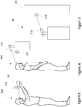
Figure 4 illustrates an example of a user using a camera system with an example hologram device; -
Figure 5 illustrates a system with an object having an example hologram device for alignment with a camera; -
Figure 6 provides a schematic illustration of an example position identification system; -
Figure 7 illustrates an example hologram device viewed from various positions; -
Figure 8 illustrates various views of an example three-dimensional object for encoding on a holographic device; and -
Figures 9A-9D illustrate example holographic images for encoding on hologram devices. - Independent claim 1 recites a camera device as according to the invention. Independent claim 9 recites a method as according to the invention. Other aspects of the invention are recited in the appended dependent claims. In various examples described herein, a hologram device is used to facilitate alignment. The hologram device may include an encoded holographic image which may have different views when viewed from various positions. Each view of the encoded image may be indicative of a position relative to alignment with a target position. The target position may be associated with a target holographic view on the encoded holographic image of the hologram device.
- In various examples, a hologram device may include conventional holograms. In other examples, the hologram device may include a multi-view, three-dimensional display. The multi-view, three-dimensional display may be formed may reproduce light rays reflecting off an object from various angles to get a different image from different perspectives, such as the different eyes of a human viewer or an imaging device positioned at different positions relative to the hologram device. In one example, the multi-view, three-dimensional display may use non-patterned grooves to send light off in different directions.
-
Figure 1 illustrates a camera device with an example hologram device. The illustratedcamera device 100 may be mobile phone or a digital camera. Thecamera device 100 includes acamera 110, such as a front-facing camera on smartphone. The camera device100 also includes adisplay 120 which provides the image seen through thecamera 110. - Often, an individual taking one's own picture looks at the screen to ensure proper alignment. This results in an image of the user with eyes drooping downward since the user is not looking into the camera. In the illustrated example, the
camera device 100 is provided with ahologram device 130 in the vicinity of thecamera 110. Thehologram device 130 provides the user with an alignment mechanism to allow the user to look closer to thecamera 110. Various examples of thehologram device 130 are described below with reference toFigures 6-9 . -
Figure 2 illustrates a camera device with another example hologram device. Thecamera device 200 ofFigure 2 is similar to thecamera device 100 ofFigure 1 and includes acamera 210, adisplay 220 and ahologram device 230. Thehologram device 230 is formed with an annular configuration and is positioned around thecamera device 210. - In the examples of
Figures 1 and 2 , the user may be allowed to look into the camera or close to the camera, rather than at the display screen. The hologram device may provide the user with an indication of proper alignment with the camera. Examples of the hologram device are described in greater detail below. Thus, the user is able to take a more desirable self-portrait. -
Figure 3 illustrates an example of asystem 300 including a user with acamera 310 having anexample hologram device 320. It is noted that, while thehologram device 320 is a flat device which may be, but does not need to be, positioned parallel to the lens,Figure 3 illustrates thehologram device 320 schematically for purposes of clarity. As described above with reference toFigures 1 and 2 , thehologram device 320 allows the user to properly align the camera to photograph himself without the use of a display. For example, the user may move the camera to achieve proper alignment using thehologram device 320. Thus, with proper alignment, the camera is pointed at the eyes of the user with the user looking into the lens of the camera. The user's head may be properly framed and rotationally aligned as well. - In other examples, as illustrated in
Figure 4 , ahologram device 420 may be used to properly position the user relative to acamera 410. Thus, the user may move and use the hologram device to properly position himself. For example, in the case of passport photos or other specialty photos or medical imaging, the user may be required to position himself in a particular manner relative to the camera or image capture device. - Referring now to
Figure 5 , asystem 500 using a hologram for alignment is illustrated. In thesystem 500 ofFigure 5 , acamera 510 may use ahologram device 520 on anobject 530 to properly align the object. For example, thecamera 510 may be associated with a robotic processor which requires theobject 530 to be in a particular position and/or orientation for processing. Thehologram 520 may indicate the current position of theobject 530. A mechanism (not shown) may be provided to change the alignment or orientation of theobject 530 based on the viewing of thehologram device 520 by thecamera 510. In one example, thecameral 510 may be mounted on a vehicle, and thehologram device 520 may be used to facilitate automated parking of the vehicle in, for example, a self-driving mode. For example, the vehicle may be a robot-driven vehicle. -
Figure 6 provides a schematic illustration of an example position identification system. In theexample system 600, ahologram device 610 is used for alignment of a visual device, such as acamera 620. In other examples, the visual device may be a human eye or any other imaging device. In the illustration ofFigure 6 , the line of sight between thecamera 620 and a target point (e.g., the center point of the hologram device) is shown asreference numeral 630, andreference numeral 632 represents the projection of the line of sight onto thehologram device 610. The position of thecamera 620 relative to the target can be represented as two angular measurements. Thefirst angle 650 is the azimuth, measured as the angle between a reference direction in the plane of the hologram device, such as thereference line 612, and the projection of the line of sight onto thehologram device 632. Thesecond angle 660 is the elevation from the plane of thehologram device 610 and the line ofsight 630. Of course, the position may be represented in a variety of other manners which are considered within the scope of the present disclosure. -
Figure 7 illustrates an example hologram device viewed from various positions. Theexample hologram device 700 may include an encoded image of a matrix of dots. Theexample hologram device 700 may also includefeatures 702 for facilitating orientation, or detection the orientation, of the hologram device. When viewed from different positions, different views of the encoded image which may be indicative of the viewer's position relative to a target. In this regard, the target may be the normal line-of-sight from theflat hologram device 700 extending through the center of thehologram device 700.Figure 7 shows a progression of views of thehologram device 700 illustrating how angular information can be transmitted optically to a viewer or an imaging device such as a camera. When the hologram device is viewed from a target position, such as from directly above the hologram device 700 (as shown inFigure 7(a) ), a target dot in the matrix of dots may appear differently from the other dots. In some examples, the target dot may appear brighter, darker or a different color, for example. The change in appearance may facilitate identification of the target position. - If the observer is positioned such that the line of sight is, for example, ten degrees from the normal in one dimension, the
hologram device 700 may appear as illustrated inFigure 7(b). Figure 7(c) illustrates thehologram device 700 as it may appear when viewed with the line ofsight 20 degrees from normal in one dimension and 20 degrees from normal in the second direction. Finally,Figure 7(d) illustrates thehologram device 700 as it may appear when viewed from an angle of five degrees from the normal in one dimension. In this regard, two adjacent dots may appear as different from the other dots in the matrix. - In some examples, the hologram device may be encoded with an image of a three-dimensional object. Such an object may allow visual alignment through viewing of an orientation of the three-dimensional object. The orientation of the object may allow determination of the change in position needed for proper alignment. In certain examples, the three-dimensional object may include an asymmetric feature which may facilitate rotational alignment. One example of a three-dimensional object having an asymmetric feature is illustrated in
Figure 8 , which includes various views of the example three-dimensional object. An image of the three-dimensional object, equivalent to a set of two-dimensional images, may be encoded as a hologram on a hologram device. - The example object of
Figure 8 is avase 800 having abody 810, ahandle 820 and anopening 830. In the illustrated example, the target alignment of the vase may be with the user looking into theopening 830 toward the bottom of the inside of thevase 800. When the hologram object is viewed from positions other than the target alignment, thevase 800 may be viewed from an off-center perspective, as illustrated inFigures 8(a) and 8(b) . As illustrated inFigure 8(c) , when properly aligned, theopening 830 of thevase 800 may change in appearance. For example, inFigure 8(c) , the opening is made darker. In other examples, the opening may be brighter, a different color or otherwise change visually. - As noted above, the three-dimensional object may include an asymmetric feature to allow proper rotational alignment. In the example of
Figure 8 , thehandle 820 of thevase 800 provides the asymmetric feature. Proper rotational alignment is achieved when thehandle 820 appears in a particular position, such as on the top side of the vase, as illustrated inFigure 8(c) . -
Figures 9A-9D illustrate example holographic images for encoding on hologram devices. In various examples, the encoded image may be sphere formed of facets, similar to a mirror ball. Each facet may include an indication of a position of the facet, for example, relative to a target facet. Thus, a view of the encoded image may correspond to one or more facets of the spherical encoded image. In different examples, the position of each facet may be indicated in different manners.Figures 9A-9D illustrate some such examples. - Referring first to
Figure 9A , each view of the encoded image may include a view of a three-dimensional object, such as the object described above with reference toFigure 8 . In this regard, each facet of the spherical object may include an image of the three-dimensional object from a different perspective. Each different perspective may be indicative of the position of the corresponding view or facet relative to a target view or perspective. - Referring now to
Figure 9B , each view of the encoded image may include numerical values indicative of the angular position of the view relative to a target view. For example, the values may be indicative of an azimuth value and an elevation angle, such as the angles described above with reference toFigure 6 . Thus, a user or a camera viewing each view may learn the position change required to align with a target view or facet. - Referring now to
Figure 9C , each view of the encoded image may include a code indicative of the position of each view relative to a target view. As illustrated inFigure 9C , the code may be a numerical value. The numerical values may be associated with a relative position through a table look-up, for example. In other examples, in place of the numerical values, each view or facet may include another machine-readable code, such as a bar code, a quick-read (QR) code or a 2-dimensional bar code. In various examples, an imaging device may be coupled to a processor. The imaging device may capture the machine-readable code, and the processor may determine the change in position required for alignment with a target view or facet. The processor may cause a change in the position based on the relative position indicated by the machine-readable code. - Referring now to
Figure 9D , each view of the encoded image may include a graphical image indicating a target view or a direction to the target view. As illustrated inFigure 9D , a target view or facet may be indicated by a target symbol, and non-target views or facets may be indicated by an arrow indicating the direction to the target. In some examples, a feature of the arrow may indicate the magnitude of change required for alignment with the target. For example, a length, thickness or brightness of the arrow may indicate a distance to the target view. - Software implementations of various examples can be accomplished with standard programming techniques with rule-based logic and other logic to accomplish various database searching steps or processes, correlation steps or processes, comparison steps or processes and decision steps or processes.
- The foregoing description of various examples has been presented for purposes of illustration and description. The examples discussed herein were chosen and described in order to explain the principles and the nature of various examples of the present disclosure and its practical application to enable one skilled in the art to utilize the present disclosure in various examples and with various modifications as are suited to the particular use contemplated.
Claims (12)
- A camera device (100; 200), comprising:a camera (110; 210; 310; 410; 510; 620); anda hologram device (130; 230; 320; 420; 520; 610; 700) in the vicinity of the camera and including an encoded holographic image providing in use a user with different views when viewed by said user from different positions, comprising:a target holographic view of the encoded holographic image (520) representing an alignment target and providing in use the user with an indication of a proper alignment with the camera; anda plurality of non-target holographic views of the encoded holographic image (520), each non-target holographic view indicating in use a viewing position relative to the target holographic view.
- The device (130; 230; 320; 420; 520; 610; 700) of claim 1, wherein the encoded holographic image (520) includes a three-dimensional object (800; 910, 920, 930, 940).
- The device (130; 230; 320; 420; 520; 610; 700) of claim 2, wherein the three-dimensional object (800; 910, 920, 930, 940) includes an asymmetric feature (820) to facilitate rotational alignment.
- The device (130; 230; 320; 420; 520; 610; 700) of claim 1, wherein each non-target holographic view of the encoded holographic image (520) includes a code associated with the position relative to the target holographic view.
- The device (130; 230; 320; 420; 520; 610; 700) of claim 4, wherein the code is a machine-readable code.
- The device (130; 230; 320; 420; 520; 610; 700) of claim 4, wherein the code is associated with the position relative to the target holographic view through a table look-up.
- The device (130; 230; 320; 420; 520; 610; 700) of claim 1, wherein each non-target holographic view of the encoded holographic image (520) includes a first angle indicative of an elevation angle and a second angle indicative of an azimuth value.
- The device (130; 230; 320; 420; 520; 610; 700) of claim 1, wherein each non-target holographic view of the encoded holographic image (520) includes a graphical representation indicative of the position relative to the target holographic view.
- A method, comprising:detecting a non-target holographic view of an encoded holographic image (520) on a hologram device (130; 230; 320; 420; 520; 610; 700), characterised in that the hologram device is in the vicinity of the camera and includes an encoded holographic image having different views when viewed by a user from different positions, and the non-target holographic view indicates a viewing position relative to a target holographic view of the encoded holographic image (520), wherein the target holographic view provides an indication to the user of a proper alignment with a camera; andcausing a change in the viewing position relative to the target holographic view based on the non-target holographic view indicating the viewing position relative to the target holographic view.
- The method of claim 9, wherein the encoded holographic image (520) includes an image of a three-dimensional object (800; 910, 920, 930, 940).
- The method of claim 10, wherein the three-dimensional object (800; 910, 920, 930, 940) includes an asymmetric feature (820) indicating a rotational orientation of the hologram device (130; 230; 320; 420; 520; 610; 700), and wherein the method further comprises:
causing a rotation to change the rotational orientation of the hologram device (130; 230; 320; 420; 520; 610; 700) based on the indication of the orientation by the asymmetric feature (820) of the three-dimensional object (800; 910, 920, 930, 940). - The method of claim 9, wherein the non-target holographic view of the encoded holographic image (520) includes a machine-readable code associated with the position relative to the target holographic view.
Applications Claiming Priority (1)
| Application Number | Priority Date | Filing Date | Title |
|---|---|---|---|
| PCT/US2013/072480 WO2015080750A1 (en) | 2013-11-29 | 2013-11-29 | Hologram for alignment |
Publications (3)
| Publication Number | Publication Date |
|---|---|
| EP3074823A1 EP3074823A1 (en) | 2016-10-05 |
| EP3074823A4 EP3074823A4 (en) | 2017-06-21 |
| EP3074823B1 true EP3074823B1 (en) | 2020-11-04 |
Family
ID=53199524
Family Applications (1)
| Application Number | Title | Priority Date | Filing Date |
|---|---|---|---|
| EP13898132.9A Active EP3074823B1 (en) | 2013-11-29 | 2013-11-29 | Hologram for alignment |
Country Status (4)
| Country | Link |
|---|---|
| US (1) | US9835448B2 (en) |
| EP (1) | EP3074823B1 (en) |
| CN (1) | CN105723285B (en) |
| WO (1) | WO2015080750A1 (en) |
Families Citing this family (5)
| Publication number | Priority date | Publication date | Assignee | Title |
|---|---|---|---|---|
| CN106842882B (en) * | 2017-04-02 | 2022-03-18 | 浙江工业大学 | Self-visible holographic display device |
| US11465840B2 (en) | 2017-11-14 | 2022-10-11 | Hai Robotics Co., Ltd. | Handling robot |
| KR102385397B1 (en) | 2017-11-14 | 2022-04-14 | 하이 로보틱스 씨오., 엘티디. | Transport Robot and Transport Robot-Based Pickup Method |
| US12006143B2 (en) | 2017-11-14 | 2024-06-11 | Hai Robotics Co., Ltd. | Handling robot |
| CA3057507C (en) * | 2018-10-03 | 2023-08-22 | Khaled Shariff | Virtual reality system and method for displaying on a real-world display a viewable portion of a source file projected on an inverse spherical virtual screen |
Family Cites Families (13)
| Publication number | Priority date | Publication date | Assignee | Title |
|---|---|---|---|---|
| US4576458A (en) | 1983-04-05 | 1986-03-18 | Fuji Photo Film Co., Ltd. | Camera finder employing holographic view field frames |
| US6559948B1 (en) | 1999-06-30 | 2003-05-06 | Raytheon Company | Method for locating a structure using holograms |
| GB0016358D0 (en) * | 2000-07-03 | 2000-08-23 | Optaglio Ltd | Optical device |
| KR100472437B1 (en) | 2001-10-06 | 2005-03-08 | 삼성전자주식회사 | Aligning method of optical system using Computer Generated Hologram and thereof apparatus |
| JP3873150B2 (en) | 2002-05-24 | 2007-01-24 | 学校法人金沢工業大学 | Two-dimensional display method and apparatus for three-dimensional vector |
| US7511805B2 (en) | 2005-11-28 | 2009-03-31 | Leica Geosystems Ag | Holographic test plate for positioning and aligning pipes |
| GB0525336D0 (en) * | 2005-12-13 | 2006-01-18 | Univ Cambridge Tech | Hologram viewing device |
| JP5099744B2 (en) | 2007-02-15 | 2012-12-19 | 船井電機株式会社 | Hologram device |
| US20100045701A1 (en) | 2008-08-22 | 2010-02-25 | Cybernet Systems Corporation | Automatic mapping of augmented reality fiducials |
| US8970690B2 (en) | 2009-02-13 | 2015-03-03 | Metaio Gmbh | Methods and systems for determining the pose of a camera with respect to at least one object of a real environment |
| US8240853B2 (en) | 2009-05-01 | 2012-08-14 | Bioptigen, Inc. | Systems for imaging structures of a subject and related methods |
| US20120104097A1 (en) * | 2009-07-09 | 2012-05-03 | Bilcare Technologies Singapore Pte. Ltd. | Reading device able to identify a tag or an object adapted to be identified, related methods and systems |
| TWI561941B (en) * | 2010-04-01 | 2016-12-11 | Seereal Technologies Sa | Method and device for encoding three-dimensional scenes which include transparent objects in a holographic system |
-
2013
- 2013-11-29 WO PCT/US2013/072480 patent/WO2015080750A1/en active Application Filing
- 2013-11-29 US US15/037,456 patent/US9835448B2/en active Active
- 2013-11-29 CN CN201380080953.7A patent/CN105723285B/en not_active Expired - Fee Related
- 2013-11-29 EP EP13898132.9A patent/EP3074823B1/en active Active
Non-Patent Citations (1)
| Title |
|---|
| None * |
Also Published As
| Publication number | Publication date |
|---|---|
| US20160305775A1 (en) | 2016-10-20 |
| CN105723285B (en) | 2018-10-12 |
| EP3074823A1 (en) | 2016-10-05 |
| US9835448B2 (en) | 2017-12-05 |
| WO2015080750A1 (en) | 2015-06-04 |
| CN105723285A (en) | 2016-06-29 |
| EP3074823A4 (en) | 2017-06-21 |
Similar Documents
| Publication | Publication Date | Title |
|---|---|---|
| EP3074823B1 (en) | Hologram for alignment | |
| US10521026B2 (en) | Passive optical and inertial tracking in slim form-factor | |
| US10146335B2 (en) | Modular extension of inertial controller for six DOF mixed reality input | |
| US8736670B2 (en) | 3D visualization system | |
| CN111246195B (en) | System for automatically defining user experience or system behavior related to scene image content | |
| CN106255978B (en) | Facial expression tracking | |
| Nishino et al. | The world in an eye [eye image interpretation] | |
| JP7480882B2 (en) | Information processing device, recognition assistance method, and computer program | |
| JP7012163B2 (en) | Head-mounted display device and its method | |
| EP3252714A1 (en) | Camera selection in positional tracking | |
| WO2013128612A1 (en) | Head mounted display, calibration method, calibration program, and recording medium | |
| KR101820632B1 (en) | Lens provided with compound eye structure and camera system including it | |
| US11402657B2 (en) | Information processing device for display device, information processing method for display device, and program for display device | |
| US11579449B2 (en) | Systems and methods for providing mixed-reality experiences under low light conditions | |
| CN109791294B (en) | Method and device for operating a display system with data glasses | |
| US12095975B2 (en) | Reverse pass-through glasses for augmented reality and virtual reality devices | |
| WO2022014305A1 (en) | Multi-pinhole camera and image identification system | |
| CN110120100B (en) | Image processing method, device and identification tracking system | |
| CN108664118B (en) | Eyeball tracking method and device, contact lenses and virtual reality system | |
| CN109394170B (en) | A kind of iris information measuring system of no-reflection | |
| US11798127B2 (en) | Spatial positioning of targeted object magnification | |
| EP3602253B1 (en) | Transparency system for commonplace camera | |
| JP2016057634A (en) | Head-mounted display, calibration method, calibration program, and recording medium | |
| CN112053444B (en) | Method for superposing virtual objects based on optical communication device and corresponding electronic equipment | |
| WO2022013878A1 (en) | Pupil ellipse-based, real-time iris localization |
Legal Events
| Date | Code | Title | Description |
|---|---|---|---|
| PUAI | Public reference made under article 153(3) epc to a published international application that has entered the european phase |
Free format text: ORIGINAL CODE: 0009012 |
|
| 17P | Request for examination filed |
Effective date: 20160404 |
|
| AK | Designated contracting states |
Kind code of ref document: A1 Designated state(s): AL AT BE BG CH CY CZ DE DK EE ES FI FR GB GR HR HU IE IS IT LI LT LU LV MC MK MT NL NO PL PT RO RS SE SI SK SM TR |
|
| AX | Request for extension of the european patent |
Extension state: BA ME |
|
| DAX | Request for extension of the european patent (deleted) | ||
| A4 | Supplementary search report drawn up and despatched |
Effective date: 20170518 |
|
| RIC1 | Information provided on ipc code assigned before grant |
Ipc: G06K 19/06 20060101ALN20170512BHEP Ipc: G06K 7/10 20060101ALN20170512BHEP Ipc: G01B 11/27 20060101ALN20170512BHEP Ipc: G06K 7/14 20060101ALN20170512BHEP Ipc: G03H 1/22 20060101ALN20170512BHEP Ipc: G03H 1/04 20060101AFI20170512BHEP Ipc: G03H 1/26 20060101ALI20170512BHEP |
|
| STAA | Information on the status of an ep patent application or granted ep patent |
Free format text: STATUS: EXAMINATION IS IN PROGRESS |
|
| 17Q | First examination report despatched |
Effective date: 20180302 |
|
| RAP1 | Party data changed (applicant data changed or rights of an application transferred) |
Owner name: HEWLETT-PACKARD DEVELOPMENT COMPANY, L.P. |
|
| RIC1 | Information provided on ipc code assigned before grant |
Ipc: G03H 1/22 20060101ALN20200526BHEP Ipc: G01B 11/27 20060101ALN20200526BHEP Ipc: G03H 1/04 20060101AFI20200526BHEP Ipc: G03H 1/26 20060101ALI20200526BHEP Ipc: G06K 7/10 20060101ALN20200526BHEP Ipc: G06K 7/14 20060101ALN20200526BHEP Ipc: G06K 19/06 20060101ALN20200526BHEP |
|
| GRAP | Despatch of communication of intention to grant a patent |
Free format text: ORIGINAL CODE: EPIDOSNIGR1 |
|
| STAA | Information on the status of an ep patent application or granted ep patent |
Free format text: STATUS: GRANT OF PATENT IS INTENDED |
|
| INTG | Intention to grant announced |
Effective date: 20200714 |
|
| RIC1 | Information provided on ipc code assigned before grant |
Ipc: G03H 1/26 20060101ALI20200703BHEP Ipc: G06K 19/06 20060101ALN20200703BHEP Ipc: G01B 11/27 20060101ALN20200703BHEP Ipc: G03H 1/22 20060101ALN20200703BHEP Ipc: G03H 1/04 20060101AFI20200703BHEP Ipc: G06K 7/14 20060101ALN20200703BHEP Ipc: G06K 7/10 20060101ALN20200703BHEP |
|
| GRAS | Grant fee paid |
Free format text: ORIGINAL CODE: EPIDOSNIGR3 |
|
| GRAA | (expected) grant |
Free format text: ORIGINAL CODE: 0009210 |
|
| STAA | Information on the status of an ep patent application or granted ep patent |
Free format text: STATUS: THE PATENT HAS BEEN GRANTED |
|
| AK | Designated contracting states |
Kind code of ref document: B1 Designated state(s): AL AT BE BG CH CY CZ DE DK EE ES FI FR GB GR HR HU IE IS IT LI LT LU LV MC MK MT NL NO PL PT RO RS SE SI SK SM TR |
|
| REG | Reference to a national code |
Ref country code: GB Ref legal event code: FG4D |
|
| REG | Reference to a national code |
Ref country code: CH Ref legal event code: EP |
|
| REG | Reference to a national code |
Ref country code: AT Ref legal event code: REF Ref document number: 1331596 Country of ref document: AT Kind code of ref document: T Effective date: 20201115 |
|
| REG | Reference to a national code |
Ref country code: IE Ref legal event code: FG4D |
|
| REG | Reference to a national code |
Ref country code: DE Ref legal event code: R096 Ref document number: 602013073888 Country of ref document: DE |
|
| REG | Reference to a national code |
Ref country code: NL Ref legal event code: MP Effective date: 20201104 |
|
| REG | Reference to a national code |
Ref country code: AT Ref legal event code: MK05 Ref document number: 1331596 Country of ref document: AT Kind code of ref document: T Effective date: 20201104 |
|
| PG25 | Lapsed in a contracting state [announced via postgrant information from national office to epo] |
Ref country code: NO Free format text: LAPSE BECAUSE OF FAILURE TO SUBMIT A TRANSLATION OF THE DESCRIPTION OR TO PAY THE FEE WITHIN THE PRESCRIBED TIME-LIMIT Effective date: 20210204 Ref country code: PT Free format text: LAPSE BECAUSE OF FAILURE TO SUBMIT A TRANSLATION OF THE DESCRIPTION OR TO PAY THE FEE WITHIN THE PRESCRIBED TIME-LIMIT Effective date: 20210304 Ref country code: FI Free format text: LAPSE BECAUSE OF FAILURE TO SUBMIT A TRANSLATION OF THE DESCRIPTION OR TO PAY THE FEE WITHIN THE PRESCRIBED TIME-LIMIT Effective date: 20201104 Ref country code: RS Free format text: LAPSE BECAUSE OF FAILURE TO SUBMIT A TRANSLATION OF THE DESCRIPTION OR TO PAY THE FEE WITHIN THE PRESCRIBED TIME-LIMIT Effective date: 20201104 Ref country code: GR Free format text: LAPSE BECAUSE OF FAILURE TO SUBMIT A TRANSLATION OF THE DESCRIPTION OR TO PAY THE FEE WITHIN THE PRESCRIBED TIME-LIMIT Effective date: 20210205 |
|
| PG25 | Lapsed in a contracting state [announced via postgrant information from national office to epo] |
Ref country code: BG Free format text: LAPSE BECAUSE OF FAILURE TO SUBMIT A TRANSLATION OF THE DESCRIPTION OR TO PAY THE FEE WITHIN THE PRESCRIBED TIME-LIMIT Effective date: 20210204 Ref country code: AT Free format text: LAPSE BECAUSE OF FAILURE TO SUBMIT A TRANSLATION OF THE DESCRIPTION OR TO PAY THE FEE WITHIN THE PRESCRIBED TIME-LIMIT Effective date: 20201104 Ref country code: ES Free format text: LAPSE BECAUSE OF FAILURE TO SUBMIT A TRANSLATION OF THE DESCRIPTION OR TO PAY THE FEE WITHIN THE PRESCRIBED TIME-LIMIT Effective date: 20201104 Ref country code: SE Free format text: LAPSE BECAUSE OF FAILURE TO SUBMIT A TRANSLATION OF THE DESCRIPTION OR TO PAY THE FEE WITHIN THE PRESCRIBED TIME-LIMIT Effective date: 20201104 Ref country code: LV Free format text: LAPSE BECAUSE OF FAILURE TO SUBMIT A TRANSLATION OF THE DESCRIPTION OR TO PAY THE FEE WITHIN THE PRESCRIBED TIME-LIMIT Effective date: 20201104 Ref country code: IS Free format text: LAPSE BECAUSE OF FAILURE TO SUBMIT A TRANSLATION OF THE DESCRIPTION OR TO PAY THE FEE WITHIN THE PRESCRIBED TIME-LIMIT Effective date: 20210304 Ref country code: PL Free format text: LAPSE BECAUSE OF FAILURE TO SUBMIT A TRANSLATION OF THE DESCRIPTION OR TO PAY THE FEE WITHIN THE PRESCRIBED TIME-LIMIT Effective date: 20201104 |
|
| REG | Reference to a national code |
Ref country code: LT Ref legal event code: MG9D |
|
| PG25 | Lapsed in a contracting state [announced via postgrant information from national office to epo] |
Ref country code: HR Free format text: LAPSE BECAUSE OF FAILURE TO SUBMIT A TRANSLATION OF THE DESCRIPTION OR TO PAY THE FEE WITHIN THE PRESCRIBED TIME-LIMIT Effective date: 20201104 |
|
| REG | Reference to a national code |
Ref country code: CH Ref legal event code: PL |
|
| PG25 | Lapsed in a contracting state [announced via postgrant information from national office to epo] |
Ref country code: CZ Free format text: LAPSE BECAUSE OF FAILURE TO SUBMIT A TRANSLATION OF THE DESCRIPTION OR TO PAY THE FEE WITHIN THE PRESCRIBED TIME-LIMIT Effective date: 20201104 Ref country code: EE Free format text: LAPSE BECAUSE OF FAILURE TO SUBMIT A TRANSLATION OF THE DESCRIPTION OR TO PAY THE FEE WITHIN THE PRESCRIBED TIME-LIMIT Effective date: 20201104 Ref country code: SM Free format text: LAPSE BECAUSE OF FAILURE TO SUBMIT A TRANSLATION OF THE DESCRIPTION OR TO PAY THE FEE WITHIN THE PRESCRIBED TIME-LIMIT Effective date: 20201104 Ref country code: RO Free format text: LAPSE BECAUSE OF FAILURE TO SUBMIT A TRANSLATION OF THE DESCRIPTION OR TO PAY THE FEE WITHIN THE PRESCRIBED TIME-LIMIT Effective date: 20201104 Ref country code: SK Free format text: LAPSE BECAUSE OF FAILURE TO SUBMIT A TRANSLATION OF THE DESCRIPTION OR TO PAY THE FEE WITHIN THE PRESCRIBED TIME-LIMIT Effective date: 20201104 Ref country code: LU Free format text: LAPSE BECAUSE OF NON-PAYMENT OF DUE FEES Effective date: 20201129 Ref country code: LT Free format text: LAPSE BECAUSE OF FAILURE TO SUBMIT A TRANSLATION OF THE DESCRIPTION OR TO PAY THE FEE WITHIN THE PRESCRIBED TIME-LIMIT Effective date: 20201104 |
|
| REG | Reference to a national code |
Ref country code: DE Ref legal event code: R097 Ref document number: 602013073888 Country of ref document: DE |
|
| REG | Reference to a national code |
Ref country code: BE Ref legal event code: MM Effective date: 20201130 |
|
| PG25 | Lapsed in a contracting state [announced via postgrant information from national office to epo] |
Ref country code: LI Free format text: LAPSE BECAUSE OF NON-PAYMENT OF DUE FEES Effective date: 20201130 Ref country code: CH Free format text: LAPSE BECAUSE OF NON-PAYMENT OF DUE FEES Effective date: 20201130 Ref country code: DK Free format text: LAPSE BECAUSE OF FAILURE TO SUBMIT A TRANSLATION OF THE DESCRIPTION OR TO PAY THE FEE WITHIN THE PRESCRIBED TIME-LIMIT Effective date: 20201104 Ref country code: MC Free format text: LAPSE BECAUSE OF FAILURE TO SUBMIT A TRANSLATION OF THE DESCRIPTION OR TO PAY THE FEE WITHIN THE PRESCRIBED TIME-LIMIT Effective date: 20201104 |
|
| REG | Reference to a national code |
Ref country code: IE Ref legal event code: MM4A |
|
| PLBE | No opposition filed within time limit |
Free format text: ORIGINAL CODE: 0009261 |
|
| STAA | Information on the status of an ep patent application or granted ep patent |
Free format text: STATUS: NO OPPOSITION FILED WITHIN TIME LIMIT |
|
| 26N | No opposition filed |
Effective date: 20210805 |
|
| PG25 | Lapsed in a contracting state [announced via postgrant information from national office to epo] |
Ref country code: IT Free format text: LAPSE BECAUSE OF FAILURE TO SUBMIT A TRANSLATION OF THE DESCRIPTION OR TO PAY THE FEE WITHIN THE PRESCRIBED TIME-LIMIT Effective date: 20201104 Ref country code: IE Free format text: LAPSE BECAUSE OF NON-PAYMENT OF DUE FEES Effective date: 20201129 Ref country code: AL Free format text: LAPSE BECAUSE OF FAILURE TO SUBMIT A TRANSLATION OF THE DESCRIPTION OR TO PAY THE FEE WITHIN THE PRESCRIBED TIME-LIMIT Effective date: 20201104 Ref country code: NL Free format text: LAPSE BECAUSE OF FAILURE TO SUBMIT A TRANSLATION OF THE DESCRIPTION OR TO PAY THE FEE WITHIN THE PRESCRIBED TIME-LIMIT Effective date: 20201104 Ref country code: FR Free format text: LAPSE BECAUSE OF NON-PAYMENT OF DUE FEES Effective date: 20210104 |
|
| PG25 | Lapsed in a contracting state [announced via postgrant information from national office to epo] |
Ref country code: SI Free format text: LAPSE BECAUSE OF FAILURE TO SUBMIT A TRANSLATION OF THE DESCRIPTION OR TO PAY THE FEE WITHIN THE PRESCRIBED TIME-LIMIT Effective date: 20201104 |
|
| PGFP | Annual fee paid to national office [announced via postgrant information from national office to epo] |
Ref country code: GB Payment date: 20211020 Year of fee payment: 9 Ref country code: DE Payment date: 20211020 Year of fee payment: 9 |
|
| PG25 | Lapsed in a contracting state [announced via postgrant information from national office to epo] |
Ref country code: IS Free format text: LAPSE BECAUSE OF FAILURE TO SUBMIT A TRANSLATION OF THE DESCRIPTION OR TO PAY THE FEE WITHIN THE PRESCRIBED TIME-LIMIT Effective date: 20210304 Ref country code: TR Free format text: LAPSE BECAUSE OF FAILURE TO SUBMIT A TRANSLATION OF THE DESCRIPTION OR TO PAY THE FEE WITHIN THE PRESCRIBED TIME-LIMIT Effective date: 20201104 Ref country code: MT Free format text: LAPSE BECAUSE OF FAILURE TO SUBMIT A TRANSLATION OF THE DESCRIPTION OR TO PAY THE FEE WITHIN THE PRESCRIBED TIME-LIMIT Effective date: 20201104 Ref country code: CY Free format text: LAPSE BECAUSE OF FAILURE TO SUBMIT A TRANSLATION OF THE DESCRIPTION OR TO PAY THE FEE WITHIN THE PRESCRIBED TIME-LIMIT Effective date: 20201104 |
|
| PG25 | Lapsed in a contracting state [announced via postgrant information from national office to epo] |
Ref country code: MK Free format text: LAPSE BECAUSE OF FAILURE TO SUBMIT A TRANSLATION OF THE DESCRIPTION OR TO PAY THE FEE WITHIN THE PRESCRIBED TIME-LIMIT Effective date: 20201104 |
|
| PG25 | Lapsed in a contracting state [announced via postgrant information from national office to epo] |
Ref country code: BE Free format text: LAPSE BECAUSE OF NON-PAYMENT OF DUE FEES Effective date: 20201130 |
|
| REG | Reference to a national code |
Ref country code: DE Ref legal event code: R119 Ref document number: 602013073888 Country of ref document: DE |
|
| GBPC | Gb: european patent ceased through non-payment of renewal fee |
Effective date: 20221129 |
|
| PG25 | Lapsed in a contracting state [announced via postgrant information from national office to epo] |
Ref country code: GB Free format text: LAPSE BECAUSE OF NON-PAYMENT OF DUE FEES Effective date: 20221129 Ref country code: DE Free format text: LAPSE BECAUSE OF NON-PAYMENT OF DUE FEES Effective date: 20230601 |