EP3074795B1 - Akustischer isolator für ein bohrlochwerkzeug - Google Patents
Akustischer isolator für ein bohrlochwerkzeug Download PDFInfo
- Publication number
- EP3074795B1 EP3074795B1 EP14796372.2A EP14796372A EP3074795B1 EP 3074795 B1 EP3074795 B1 EP 3074795B1 EP 14796372 A EP14796372 A EP 14796372A EP 3074795 B1 EP3074795 B1 EP 3074795B1
- Authority
- EP
- European Patent Office
- Prior art keywords
- tool
- acoustic
- attenuation element
- transmitter
- attenuation
- Prior art date
- Legal status (The legal status is an assumption and is not a legal conclusion. Google has not performed a legal analysis and makes no representation as to the accuracy of the status listed.)
- Active
Links
Images
Classifications
-
- G—PHYSICS
- G01—MEASURING; TESTING
- G01V—GEOPHYSICS; GRAVITATIONAL MEASUREMENTS; DETECTING MASSES OR OBJECTS; TAGS
- G01V1/00—Seismology; Seismic or acoustic prospecting or detecting
- G01V1/40—Seismology; Seismic or acoustic prospecting or detecting specially adapted for well-logging
- G01V1/44—Seismology; Seismic or acoustic prospecting or detecting specially adapted for well-logging using generators and receivers in the same well
-
- G—PHYSICS
- G01—MEASURING; TESTING
- G01V—GEOPHYSICS; GRAVITATIONAL MEASUREMENTS; DETECTING MASSES OR OBJECTS; TAGS
- G01V1/00—Seismology; Seismic or acoustic prospecting or detecting
- G01V1/40—Seismology; Seismic or acoustic prospecting or detecting specially adapted for well-logging
- G01V1/52—Structural details
- G01V1/523—Damping devices
Definitions
- the present disclosure relates in general to a system for use in imaging a subterranean borehole. More specifically, the present disclosure relates to a downhole imaging system having an acoustic isolator for attenuating acoustic signals in the system.
- US 3 982 606 A discloses an acoustical logging apparatus having a signal interference means comprising a rotating sleeve with signal attenuation elements mounted thereon which extend to the wall of the borehole to act as a centralizer when in the borehole.
- US 2005/167101 A discloses an acoustic isolator comprising mechanical mass-spring systems.
- US 4 446 539 A discloses a sonic logging tool which includes a relatively short sonic wave isolation section, having interlocking ends having serpentine edges which are spaced from each other, but which are interlocked for preventing longitudinal separation of the two ends, and a damping material disposed between the spatially separated serpentine edges.
- Geological data concerning subterranean formations is often gathered with an imaging technique.
- the data obtained usually relates to formation resistivity, formation porosity and/or permeability, identification of formation strata and the like. Zones of entrained hydrocarbons and reservoir production capabilities can be determined using this data.
- the imaging is obtained with a downhole logging tool, which is deployed into a well that extends into the subterranean formation.
- Example downhole tools for imaging include resistivity tools, nuclear magnetic resonance (NMR) devices, and acoustic sensors.
- Resistivity tools usually include electrodes on one portion of the tool that are energized to emit a current into the formation, which is measured with sensors on another part of the tool.
- NMR devices release radiation that scatters from the formation, which is analyzed for assessing formation details. Similar to radiation devices, acoustic devices analyze acoustic data that reflects from the formation. Acoustic imaging tools though are susceptible to erroneous readings when the acoustic signals travel from the transmitter along the tool housing and directly to receivers in the tool.
- an acoustic tool for imaging in a subterranean wellbore that includes an acoustic transmitter, an acoustic receiver spaced axially away from the transmitter, and an elongate attenuation element that is between the transmitter and receiver.
- the attenuation element includes an end that is spherically shaped, and that is inserted into an open end of a sleeve.
- a communication path is defined by a transmission of acoustic signals between the transmitter and receiver, and a lock ring contacts the end of the attenuation element.
- a contact interface between the lock ring and the attenuation element is in the communication path and defines a reduction in cross sectional area of the communication path.
- the end of the attenuation element has a first end and a second end that is rounded and inserted into an open end of a sleeve.
- This example of the tool further includes a multiplicity of attenuation elements, a multiplicity of sleeves and lock rings for coupling the attenuation element in series, and thereby forming a multiplicity of contact interfaces that each attenuate acoustic signals that propagate along the communication path.
- the tool may further include an oil filled tube inserted into a bore that extends axially through each of the attenuation elements, and lines in the tube that selectively couple with the transmitter and receiver.
- the lock ring spaces the sleeve radially away from the attenuation element.
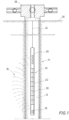
- Figure 1 shows in side partial sectional view an embodiment of a downhole tool 10 deployed in borehole 12.
- borehole 12 intersects a subterranean formation 14, where the downhole tool 10 is used for acoustically interrogating the formation 14 from within borehole 12.
- a transmitter 16 shown generating acoustic waves 18 that propagate from the tool 10, through borehole 12, and into the formation 14.
- Some of the acoustic waves 18 reflect from within the formation 14, and propagate back to acoustic receivers 20, shown provided on a part of the tool 10 different where the transmitter 16 is located.
- the acoustic sensors 20 sense and record the waves 18.
- analyzing the waves 18 can yield information about the formation 14; such as the presence and/or amount of hydrocarbons in the formation 14.
- an example of an acoustic attenuator 22 is shown included with the tool 10 and disposed between the transmitter 16 and receivers 20. Further in the example of Figure 1 , the downhole tool 10 is deployed on a wireline 24 in the borehole, wherein optionally the wireline 24 can be coiled tubing or any other conveyance means for lowering and raising a tool within the borehole 12. Further shown is a wellhead assembly 26 at the opening to the wellbore 12 and on surface 28. As shown, wireline 24 is threaded through the wellhead assembly 26 from surface and into the wellbore 12.
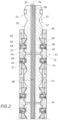
- Figure 2 provides a side sectional view of an example of the acoustic attenuator 22, which is shown as having a bore 30 that extends therethrough and substantially aligned with an axis AX of the attenuator 22.
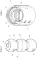
- attenuation elements 32 which as shown in perspective view in Figure 3 , are generally elongate elements. Attenuation elements 32 have opposing ends 34, a portion of each of which approximates a spherical shape.
- the mid portion 36 of the attenuation element 32 of Figures 2 and 3 has an outer radius that is about the same as the radius of each of the ends 34 from the axis AX.
- each profile 37 has a generally curved shape from its low point and up to the maximum radius portions of each end 34. Whereas the profile 37 increases generally linearly from its low point and to the maximum radius region of the mid portion 36. Keyholes 38 are shown formed radially inward into the attenuation element 32 and from an outer surface of the ends 34.0
- an anti-rotation pin 40 having a radially inward projecting end that projects into the keyhole 38.
- An end the anti-rotation pin 40 distal from keyhole 38 is illustrated coupled with a sleeve 42; where sleeve 42 circumscribes respective ends 34 of two adjacent attenuation elements 32.
- inserting the anti-rotation pins 40 through the sleeves 42 and into the attenuation elements 32 limits relative rotation of attenuation elements 32.
- Openings 44 are provided in the sleeve 42 to allow insertion of the anti-rotation pins 40.
- FIG. 4 a perspective view of the sleeve 42 is shown having the openings 44 formed through its sidewall, and a main bore 46 extending axially through the sleeve 42.
- a ridge 48 is shown within bore 46 and projects radially inward from the outer surface of the bore 46 and proximate an axial mid portion of the sleeve 42.
- threads 49 formed in the bore 46 and at the outer axial portions of sleeve 42.
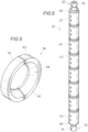
- Lock rings 50 are shown inserted in spaces between sleeves 42 and outer peripheries of ends 34. As explained in more detail below, the lock rings 50 in combination with the sleeves 42, are used for coupling together adjacent attenuation elements 32. Referring back to Figure 2 , lateral sides of lock rings 50 abut shoulders 51 in sleeves 42 that are defined where the radius of the bore 46 reduces and projects radially inward. As shown in perspective view of Figure 5 , each lock ring 50 is made up of C-shaped halves 52, 54 that when joined as shown form an axial bore 56 through the lock, ring 50. Bore 56 tapers radially inward from a lateral side 57 and defines an oblique surface.
- a portion of the oblique surface is in contact with the outer radial surface of the end 34 of attenuation element 32.
- Strategically profiling the outer surface of end 34 and bore 56 defines a contact interface 58 between lock ring 50 and attenuation element 32.
- the contact interface extends along a curved path, and may optionally circumscribe axis AX, thereby forming a continuous loop.
- an advantage of limiting contact between the element 32 and lock ring 50 to a thin contact interface 58 is that the communication path that extends directly between the transmitter 16 and receiver 20 has a significantly reduced cross-sectional area. Reducing the cross-sectional area of the acoustic communication path between the transmitter 16 and receivers 20 significantly attenuates the acoustic signal between the transmitter 16 and receivers 20.
- annular lock nut 60 is shown connected via a threaded connection 62 to the openings of each sleeve 42.
- An axial end of each lock nut 60 is in contact with a side of lock ring 50 opposite its lateral side 57, thereby axially retaining the lock ring 50 in its place as shown, and in contact with the ends 34 and the attenuation elements 32.
- an axial gap 64 is shown between adjacent attenuation elements, wherein in one example wellbore fluid fills the gap 64 thereby enhancing the attenuation capabilities of the acoustic attenuator 22.
- a tube 60 may be inserted into gap 30, and filled with an oil, which in one example may be dielectric.
- wires 68 can be inserted into the tube 66 and reduce the risk of electrical shorting due to the presence of the dielectric fluid.
- Figure 6 illustrates in perspective view an assembled example of the acoustic attenuator 22 wherein ends 34 of an attenuation element project axially outward from lock nuts 60 shown threadingly engaged with oppositely located sleeves 42 on the acoustic attenuator 22.
- the presence of the series of acoustic elements 32 within the acoustic attenuator 22 severely attenuates any waves 18 that may attempt to propagate along the body of the tool 10 so that acoustic events sensed by the receivers 20 can be isolated to those waves 18 that reflect from the formation 14 rather than propagating lengthwise across the body of the tool 10.
Landscapes
- Physics & Mathematics (AREA)
- Life Sciences & Earth Sciences (AREA)
- Engineering & Computer Science (AREA)
- Acoustics & Sound (AREA)
- Environmental & Geological Engineering (AREA)
- Geology (AREA)
- Remote Sensing (AREA)
- General Life Sciences & Earth Sciences (AREA)
- General Physics & Mathematics (AREA)
- Geophysics (AREA)
- Geophysics And Detection Of Objects (AREA)
Claims (4)
- Akustisches Werkzeug (10) für eine Bildgebung in einem unterirdischen Bohrloch, das Werkzeug umfassend:einen akustischen Sender (16);einen akustischen Empfänger (20), der axial weg von dem Sender (16) beabstandet ist;ein längliches Dämpfungselement (32), das sich zwischen dem Sender (16) und dem Empfänger (20) befindet und das in ein offenes Ende einer Hülse (42) eingesetzt ist;einen Kommunikationspfad, der durch eine Sendung akustischer Signale zwischen dem Sender (16) und dem Empfänger (20) definiert ist; undeinen Verriegelungsring (50), der das Ende des Dämpfungselements (32) berührt, wie um das Ende in der Hülse (42) zu halten;gekennzeichnet durch:
eine Kontaktschnittstelle (58) zwischen dem Verriegelungsring (50) und dem Dämpfungselement (32), die einer gekrümmten Route folgt, sich in dem Kommunikationspfad befindet und die eine Verringerung der Querschnittsfläche des Kommunikationspfads definiert; und wobei das Dämpfungselement (32) ein Ende umfasst, das kugelförmig geformt ist. - Werkzeug nach Anspruch 1, wobei das Ende des Dämpfungselements (32) ein erstes Ende (34) umfasst, das Dämpfungselement (32) ferner umfassend ein zweites Ende (34), das abgerundet und in ein offenes Ende einer Hülse (42) eingesetzt ist, das Werkzeug ferner umfassend eine Vielzahl von Dämpfungselementen (32), eine Vielzahl von Hülsen (42) und Verriegelungsringen (50) zum Koppeln des Dämpfungselements (32) in Reihe, und wobei dadurch eine Vielzahl von Kontaktschnittstellen (58) ausgebildet werden, die jeweils akustische Signale dämpfen, die sich entlang des Kommunikationspfades ausbreiten.
- Werkzeug nach Anspruch 1 oder 2, ferner umfassend ein ölgefülltes Rohr (60), das in eine Bohrung eingesetzt ist, die sich axial durch jedes der Dämpfungselemente (32) erstreckt, und Leitungen in dem Rohr, die mit dem Sender (16) und dem Empfänger (20) wahlweise gekoppelt sind.
- Werkzeug nach einem der vorstehenden Ansprüche, wobei der Verriegelungsring (50) die Hülse (42) radial weg von dem Dämpfungselement (32) beabstandet.
Applications Claiming Priority (2)
| Application Number | Priority Date | Filing Date | Title |
|---|---|---|---|
| US14/092,170 US9448320B2 (en) | 2013-11-27 | 2013-11-27 | Acoustic isolater for a downhole tool |
| PCT/US2014/063154 WO2015080829A1 (en) | 2013-11-27 | 2014-10-30 | Acoustic isolator for a downhole tool |
Publications (2)
| Publication Number | Publication Date |
|---|---|
| EP3074795A1 EP3074795A1 (de) | 2016-10-05 |
| EP3074795B1 true EP3074795B1 (de) | 2023-06-07 |
Family
ID=51871324
Family Applications (1)
| Application Number | Title | Priority Date | Filing Date |
|---|---|---|---|
| EP14796372.2A Active EP3074795B1 (de) | 2013-11-27 | 2014-10-30 | Akustischer isolator für ein bohrlochwerkzeug |
Country Status (5)
| Country | Link |
|---|---|
| US (1) | US9448320B2 (de) |
| EP (1) | EP3074795B1 (de) |
| CN (1) | CN105745557B (de) |
| CA (1) | CA2931202C (de) |
| WO (1) | WO2015080829A1 (de) |
Families Citing this family (6)
| Publication number | Priority date | Publication date | Assignee | Title |
|---|---|---|---|---|
| US20190086572A1 (en) * | 2017-09-20 | 2019-03-21 | Gowell International, Llc | Apparatus and Method of Quasiperiodic Sequence Acoustic Isolator for Down-Hole Applications |
| WO2020163870A1 (en) * | 2019-02-09 | 2020-08-13 | Baker Hughes Oilfield Operations Llc | Acoustic isolation devices for acoustic well logging tools |
| US11513249B2 (en) | 2019-10-11 | 2022-11-29 | Scientific Drilling International, Inc. | Downhole acoustic device |
| US11512586B2 (en) | 2020-10-06 | 2022-11-29 | Halliburton Energy Services, Inc. | Logging while drilling tool |
| WO2023003964A1 (en) * | 2021-07-20 | 2023-01-26 | Baker Hughes Oilfield Operations Llc | System and method for acoustic isolators |
| US11840924B2 (en) | 2021-11-24 | 2023-12-12 | Halliburton Energy Services, Inc. | Short and wideband isolator for acoustic tools |
Family Cites Families (19)
| Publication number | Priority date | Publication date | Assignee | Title |
|---|---|---|---|---|
| US3205970A (en) | 1958-12-29 | 1965-09-14 | Texaco Inc | Acoustical well logging tool |
| US4066995A (en) | 1975-01-12 | 1978-01-03 | Sperry Rand Corporation | Acoustic isolation for a telemetry system on a drill string |
| US3982606A (en) | 1975-01-22 | 1976-09-28 | Mobil Oil Corporation | Acoustical logging apparatus having signal delay means |
| US4446539A (en) | 1980-07-03 | 1984-05-01 | Bell Petroleum Services, Inc. | Sonic logging tool |
| US4872526A (en) | 1988-07-18 | 1989-10-10 | Schlumberger Technology Corporation | Sonic well logging tool longitudinal wave attenuator |
| US5357481A (en) | 1992-11-04 | 1994-10-18 | Western Atlas International, Inc. | Borehole logging tool |
| US5229553A (en) | 1992-11-04 | 1993-07-20 | Western Atlas International, Inc. | Acoustic isolator for a borehole logging tool |
| US5510582A (en) | 1995-03-06 | 1996-04-23 | Halliburton Company | Acoustic attenuator, well logging apparatus and method of well logging |
| US5852262A (en) | 1995-09-28 | 1998-12-22 | Magnetic Pulse, Inc. | Acoustic formation logging tool with improved transmitter |
| US5728978A (en) | 1996-08-02 | 1998-03-17 | Computalog U.S.A., Inc. | Acoustic isolator for acoustic well logging tool |
| US5731550A (en) | 1997-03-07 | 1998-03-24 | Western Atlas International, Inc. | Acoustic dipole well logging instrument |
| US7028806B2 (en) | 1999-06-03 | 2006-04-18 | Baker Hughes Incorporated | Acoustic isolator for downhole applications |
| US6834743B2 (en) | 2001-12-07 | 2004-12-28 | Haliburton Energy Services, Inc. | Wideband isolator for acoustic tools |
| US6820716B2 (en) * | 2003-01-16 | 2004-11-23 | Baker Hughes Incorporated | Acoustic isolator for well logging system |
| US7216737B2 (en) * | 2004-02-03 | 2007-05-15 | Schlumberger Technology Corporation | Acoustic isolator between downhole transmitters and receivers |
| US8270251B2 (en) | 2005-12-05 | 2012-09-18 | Xact Downhole Telemetry Inc. | Acoustic isolator |
| GB2444077B (en) * | 2006-11-23 | 2011-07-27 | Reeves Wireline Tech Ltd | Acoustic isolator section |
| US20090107757A1 (en) * | 2007-10-24 | 2009-04-30 | Baker Hughes Incorporated | Acoustic Isolator |
| CN201277029Y (zh) * | 2008-10-23 | 2009-07-22 | 中国海洋石油总公司 | 一种声波接收探头单元的隔声及防震结构 |
-
2013
- 2013-11-27 US US14/092,170 patent/US9448320B2/en active Active
-
2014
- 2014-10-30 CA CA2931202A patent/CA2931202C/en active Active
- 2014-10-30 EP EP14796372.2A patent/EP3074795B1/de active Active
- 2014-10-30 CN CN201480065055.9A patent/CN105745557B/zh active Active
- 2014-10-30 WO PCT/US2014/063154 patent/WO2015080829A1/en not_active Ceased
Also Published As
| Publication number | Publication date |
|---|---|
| US20150146501A1 (en) | 2015-05-28 |
| WO2015080829A1 (en) | 2015-06-04 |
| US9448320B2 (en) | 2016-09-20 |
| EP3074795A1 (de) | 2016-10-05 |
| CA2931202A1 (en) | 2015-06-04 |
| CN105745557A (zh) | 2016-07-06 |
| CA2931202C (en) | 2023-03-21 |
| CN105745557B (zh) | 2018-04-20 |
Similar Documents
| Publication | Publication Date | Title |
|---|---|---|
| EP3074795B1 (de) | Akustischer isolator für ein bohrlochwerkzeug | |
| EP2758627B1 (de) | Verfahren zur echtzeitüberwachung und übertragung seismisch/hydraulischer frakturereignisse an oberflächen mit pilotbohrung zur behandlung eines bohrlochs als überwachungsbohrloch | |
| NL1017664C2 (nl) | Systeem en werkwijze voor het controleren van een reservoir en plaatsen van een boorgat onder gebruik maken van een buis. | |
| EP2764200B1 (de) | Verfahren zur echtzeitüberwachung und übertragung seismisch/hydraulischer frakturereignisse an oberflächen mit der pilotbohrung zur behandlung eines bohrlochs als überwachungsbohrloch | |
| EP3111032B1 (de) | Drahtrohrübertragungsvorrichtung mit elektromagnetischem richtkoppler | |
| US10598810B2 (en) | Optical magnetic field sensor units for a downhole environment | |
| US11668185B2 (en) | In-cutter sensor LWD tool and method | |
| NO348424B1 (en) | Electromagnetic telemetry apparatus and methods for use in wellbore applications | |
| US20170328144A1 (en) | Centralizer electronics housing | |
| AU2017349451B2 (en) | Communication systems and methods | |
| WO2020139366A1 (en) | Downhole shock sensor | |
| US11143777B2 (en) | Quadruple transmitter and methods to determine wave velocities of a downhole formation | |
| US11428841B2 (en) | Retaining a plurality of ferrite objects in an antenna of a downhole tool | |
| US10914167B2 (en) | System for deploying communication components in a borehole | |
| CA3089099C (en) | Parallel coil paths for downhole antennas | |
| Berro et al. | Review of commercial telemetry systems for real time data transmission in boreholes | |
| GB2406347A (en) | Logging while tripping with a modified tubular |
Legal Events
| Date | Code | Title | Description |
|---|---|---|---|
| PUAI | Public reference made under article 153(3) epc to a published international application that has entered the european phase |
Free format text: ORIGINAL CODE: 0009012 |
|
| 17P | Request for examination filed |
Effective date: 20160627 |
|
| AK | Designated contracting states |
Kind code of ref document: A1 Designated state(s): AL AT BE BG CH CY CZ DE DK EE ES FI FR GB GR HR HU IE IS IT LI LT LU LV MC MK MT NL NO PL PT RO RS SE SI SK SM TR |
|
| AX | Request for extension of the european patent |
Extension state: BA ME |
|
| DAX | Request for extension of the european patent (deleted) | ||
| STAA | Information on the status of an ep patent application or granted ep patent |
Free format text: STATUS: EXAMINATION IS IN PROGRESS |
|
| 17Q | First examination report despatched |
Effective date: 20210302 |
|
| GRAP | Despatch of communication of intention to grant a patent |
Free format text: ORIGINAL CODE: EPIDOSNIGR1 |
|
| STAA | Information on the status of an ep patent application or granted ep patent |
Free format text: STATUS: GRANT OF PATENT IS INTENDED |
|
| INTG | Intention to grant announced |
Effective date: 20221202 |
|
| GRAS | Grant fee paid |
Free format text: ORIGINAL CODE: EPIDOSNIGR3 |
|
| GRAA | (expected) grant |
Free format text: ORIGINAL CODE: 0009210 |
|
| STAA | Information on the status of an ep patent application or granted ep patent |
Free format text: STATUS: THE PATENT HAS BEEN GRANTED |
|
| AK | Designated contracting states |
Kind code of ref document: B1 Designated state(s): AL AT BE BG CH CY CZ DE DK EE ES FI FR GB GR HR HU IE IS IT LI LT LU LV MC MK MT NL NO PL PT RO RS SE SI SK SM TR |
|
| RAP1 | Party data changed (applicant data changed or rights of an application transferred) |
Owner name: BAKER HUGHES ENERGY MANUFACTURING LLC |
|
| REG | Reference to a national code |
Ref country code: GB Ref legal event code: FG4D |
|
| REG | Reference to a national code |
Ref country code: CH Ref legal event code: EP Ref country code: AT Ref legal event code: REF Ref document number: 1576790 Country of ref document: AT Kind code of ref document: T Effective date: 20230615 |
|
| REG | Reference to a national code |
Ref country code: DE Ref legal event code: R096 Ref document number: 602014087211 Country of ref document: DE |
|
| P01 | Opt-out of the competence of the unified patent court (upc) registered |
Effective date: 20230526 |
|
| REG | Reference to a national code |
Ref country code: LT Ref legal event code: MG9D |
|
| REG | Reference to a national code |
Ref country code: NO Ref legal event code: T2 Effective date: 20230607 |
|
| REG | Reference to a national code |
Ref country code: NL Ref legal event code: MP Effective date: 20230607 |
|
| PG25 | Lapsed in a contracting state [announced via postgrant information from national office to epo] |
Ref country code: SE Free format text: LAPSE BECAUSE OF FAILURE TO SUBMIT A TRANSLATION OF THE DESCRIPTION OR TO PAY THE FEE WITHIN THE PRESCRIBED TIME-LIMIT Effective date: 20230607 Ref country code: ES Free format text: LAPSE BECAUSE OF FAILURE TO SUBMIT A TRANSLATION OF THE DESCRIPTION OR TO PAY THE FEE WITHIN THE PRESCRIBED TIME-LIMIT Effective date: 20230607 |
|
| REG | Reference to a national code |
Ref country code: AT Ref legal event code: MK05 Ref document number: 1576790 Country of ref document: AT Kind code of ref document: T Effective date: 20230607 |
|
| PG25 | Lapsed in a contracting state [announced via postgrant information from national office to epo] |
Ref country code: RS Free format text: LAPSE BECAUSE OF FAILURE TO SUBMIT A TRANSLATION OF THE DESCRIPTION OR TO PAY THE FEE WITHIN THE PRESCRIBED TIME-LIMIT Effective date: 20230607 Ref country code: NL Free format text: LAPSE BECAUSE OF FAILURE TO SUBMIT A TRANSLATION OF THE DESCRIPTION OR TO PAY THE FEE WITHIN THE PRESCRIBED TIME-LIMIT Effective date: 20230607 Ref country code: LV Free format text: LAPSE BECAUSE OF FAILURE TO SUBMIT A TRANSLATION OF THE DESCRIPTION OR TO PAY THE FEE WITHIN THE PRESCRIBED TIME-LIMIT Effective date: 20230607 Ref country code: LT Free format text: LAPSE BECAUSE OF FAILURE TO SUBMIT A TRANSLATION OF THE DESCRIPTION OR TO PAY THE FEE WITHIN THE PRESCRIBED TIME-LIMIT Effective date: 20230607 Ref country code: HR Free format text: LAPSE BECAUSE OF FAILURE TO SUBMIT A TRANSLATION OF THE DESCRIPTION OR TO PAY THE FEE WITHIN THE PRESCRIBED TIME-LIMIT Effective date: 20230607 Ref country code: GR Free format text: LAPSE BECAUSE OF FAILURE TO SUBMIT A TRANSLATION OF THE DESCRIPTION OR TO PAY THE FEE WITHIN THE PRESCRIBED TIME-LIMIT Effective date: 20230908 |
|
| PG25 | Lapsed in a contracting state [announced via postgrant information from national office to epo] |
Ref country code: FI Free format text: LAPSE BECAUSE OF FAILURE TO SUBMIT A TRANSLATION OF THE DESCRIPTION OR TO PAY THE FEE WITHIN THE PRESCRIBED TIME-LIMIT Effective date: 20230607 |
|
| PG25 | Lapsed in a contracting state [announced via postgrant information from national office to epo] |
Ref country code: SK Free format text: LAPSE BECAUSE OF FAILURE TO SUBMIT A TRANSLATION OF THE DESCRIPTION OR TO PAY THE FEE WITHIN THE PRESCRIBED TIME-LIMIT Effective date: 20230607 |
|
| PG25 | Lapsed in a contracting state [announced via postgrant information from national office to epo] |
Ref country code: IS Free format text: LAPSE BECAUSE OF FAILURE TO SUBMIT A TRANSLATION OF THE DESCRIPTION OR TO PAY THE FEE WITHIN THE PRESCRIBED TIME-LIMIT Effective date: 20231007 |
|
| PG25 | Lapsed in a contracting state [announced via postgrant information from national office to epo] |
Ref country code: SM Free format text: LAPSE BECAUSE OF FAILURE TO SUBMIT A TRANSLATION OF THE DESCRIPTION OR TO PAY THE FEE WITHIN THE PRESCRIBED TIME-LIMIT Effective date: 20230607 Ref country code: SK Free format text: LAPSE BECAUSE OF FAILURE TO SUBMIT A TRANSLATION OF THE DESCRIPTION OR TO PAY THE FEE WITHIN THE PRESCRIBED TIME-LIMIT Effective date: 20230607 Ref country code: RO Free format text: LAPSE BECAUSE OF FAILURE TO SUBMIT A TRANSLATION OF THE DESCRIPTION OR TO PAY THE FEE WITHIN THE PRESCRIBED TIME-LIMIT Effective date: 20230607 Ref country code: PT Free format text: LAPSE BECAUSE OF FAILURE TO SUBMIT A TRANSLATION OF THE DESCRIPTION OR TO PAY THE FEE WITHIN THE PRESCRIBED TIME-LIMIT Effective date: 20231009 Ref country code: IS Free format text: LAPSE BECAUSE OF FAILURE TO SUBMIT A TRANSLATION OF THE DESCRIPTION OR TO PAY THE FEE WITHIN THE PRESCRIBED TIME-LIMIT Effective date: 20231007 Ref country code: EE Free format text: LAPSE BECAUSE OF FAILURE TO SUBMIT A TRANSLATION OF THE DESCRIPTION OR TO PAY THE FEE WITHIN THE PRESCRIBED TIME-LIMIT Effective date: 20230607 Ref country code: CZ Free format text: LAPSE BECAUSE OF FAILURE TO SUBMIT A TRANSLATION OF THE DESCRIPTION OR TO PAY THE FEE WITHIN THE PRESCRIBED TIME-LIMIT Effective date: 20230607 Ref country code: AT Free format text: LAPSE BECAUSE OF FAILURE TO SUBMIT A TRANSLATION OF THE DESCRIPTION OR TO PAY THE FEE WITHIN THE PRESCRIBED TIME-LIMIT Effective date: 20230607 |
|
| PG25 | Lapsed in a contracting state [announced via postgrant information from national office to epo] |
Ref country code: PL Free format text: LAPSE BECAUSE OF FAILURE TO SUBMIT A TRANSLATION OF THE DESCRIPTION OR TO PAY THE FEE WITHIN THE PRESCRIBED TIME-LIMIT Effective date: 20230607 |
|
| REG | Reference to a national code |
Ref country code: DE Ref legal event code: R097 Ref document number: 602014087211 Country of ref document: DE |
|
| PLBE | No opposition filed within time limit |
Free format text: ORIGINAL CODE: 0009261 |
|
| STAA | Information on the status of an ep patent application or granted ep patent |
Free format text: STATUS: NO OPPOSITION FILED WITHIN TIME LIMIT |
|
| PG25 | Lapsed in a contracting state [announced via postgrant information from national office to epo] |
Ref country code: DK Free format text: LAPSE BECAUSE OF FAILURE TO SUBMIT A TRANSLATION OF THE DESCRIPTION OR TO PAY THE FEE WITHIN THE PRESCRIBED TIME-LIMIT Effective date: 20230607 |
|
| REG | Reference to a national code |
Ref country code: DE Ref legal event code: R119 Ref document number: 602014087211 Country of ref document: DE |
|
| PG25 | Lapsed in a contracting state [announced via postgrant information from national office to epo] |
Ref country code: SI Free format text: LAPSE BECAUSE OF FAILURE TO SUBMIT A TRANSLATION OF THE DESCRIPTION OR TO PAY THE FEE WITHIN THE PRESCRIBED TIME-LIMIT Effective date: 20230607 |
|
| 26N | No opposition filed |
Effective date: 20240308 |
|
| PG25 | Lapsed in a contracting state [announced via postgrant information from national office to epo] |
Ref country code: SI Free format text: LAPSE BECAUSE OF FAILURE TO SUBMIT A TRANSLATION OF THE DESCRIPTION OR TO PAY THE FEE WITHIN THE PRESCRIBED TIME-LIMIT Effective date: 20230607 Ref country code: IT Free format text: LAPSE BECAUSE OF FAILURE TO SUBMIT A TRANSLATION OF THE DESCRIPTION OR TO PAY THE FEE WITHIN THE PRESCRIBED TIME-LIMIT Effective date: 20230607 Ref country code: MC Free format text: LAPSE BECAUSE OF FAILURE TO SUBMIT A TRANSLATION OF THE DESCRIPTION OR TO PAY THE FEE WITHIN THE PRESCRIBED TIME-LIMIT Effective date: 20230607 |
|
| REG | Reference to a national code |
Ref country code: CH Ref legal event code: PL |
|
| REG | Reference to a national code |
Ref country code: BE Ref legal event code: MM Effective date: 20231031 |
|
| PG25 | Lapsed in a contracting state [announced via postgrant information from national office to epo] |
Ref country code: LU Free format text: LAPSE BECAUSE OF NON-PAYMENT OF DUE FEES Effective date: 20231030 |
|
| PG25 | Lapsed in a contracting state [announced via postgrant information from national office to epo] |
Ref country code: LU Free format text: LAPSE BECAUSE OF NON-PAYMENT OF DUE FEES Effective date: 20231030 |
|
| PG25 | Lapsed in a contracting state [announced via postgrant information from national office to epo] |
Ref country code: CH Free format text: LAPSE BECAUSE OF NON-PAYMENT OF DUE FEES Effective date: 20231031 |
|
| PG25 | Lapsed in a contracting state [announced via postgrant information from national office to epo] |
Ref country code: FR Free format text: LAPSE BECAUSE OF NON-PAYMENT OF DUE FEES Effective date: 20231031 Ref country code: DE Free format text: LAPSE BECAUSE OF NON-PAYMENT OF DUE FEES Effective date: 20240501 Ref country code: CH Free format text: LAPSE BECAUSE OF NON-PAYMENT OF DUE FEES Effective date: 20231031 |
|
| PG25 | Lapsed in a contracting state [announced via postgrant information from national office to epo] |
Ref country code: BE Free format text: LAPSE BECAUSE OF NON-PAYMENT OF DUE FEES Effective date: 20231031 |
|
| PG25 | Lapsed in a contracting state [announced via postgrant information from national office to epo] |
Ref country code: IE Free format text: LAPSE BECAUSE OF NON-PAYMENT OF DUE FEES Effective date: 20231030 |
|
| PGFP | Annual fee paid to national office [announced via postgrant information from national office to epo] |
Ref country code: GB Payment date: 20240919 Year of fee payment: 11 |
|
| PG25 | Lapsed in a contracting state [announced via postgrant information from national office to epo] |
Ref country code: IE Free format text: LAPSE BECAUSE OF NON-PAYMENT OF DUE FEES Effective date: 20231030 |
|
| PGFP | Annual fee paid to national office [announced via postgrant information from national office to epo] |
Ref country code: NO Payment date: 20240923 Year of fee payment: 11 |
|
| PG25 | Lapsed in a contracting state [announced via postgrant information from national office to epo] |
Ref country code: BG Free format text: LAPSE BECAUSE OF FAILURE TO SUBMIT A TRANSLATION OF THE DESCRIPTION OR TO PAY THE FEE WITHIN THE PRESCRIBED TIME-LIMIT Effective date: 20230607 |
|
| PG25 | Lapsed in a contracting state [announced via postgrant information from national office to epo] |
Ref country code: BG Free format text: LAPSE BECAUSE OF FAILURE TO SUBMIT A TRANSLATION OF THE DESCRIPTION OR TO PAY THE FEE WITHIN THE PRESCRIBED TIME-LIMIT Effective date: 20230607 |
|
| PG25 | Lapsed in a contracting state [announced via postgrant information from national office to epo] |
Ref country code: CY Free format text: LAPSE BECAUSE OF FAILURE TO SUBMIT A TRANSLATION OF THE DESCRIPTION OR TO PAY THE FEE WITHIN THE PRESCRIBED TIME-LIMIT; INVALID AB INITIO Effective date: 20141030 |
|
| PG25 | Lapsed in a contracting state [announced via postgrant information from national office to epo] |
Ref country code: HU Free format text: LAPSE BECAUSE OF FAILURE TO SUBMIT A TRANSLATION OF THE DESCRIPTION OR TO PAY THE FEE WITHIN THE PRESCRIBED TIME-LIMIT; INVALID AB INITIO Effective date: 20141030 |
|
| PG25 | Lapsed in a contracting state [announced via postgrant information from national office to epo] |
Ref country code: TR Free format text: LAPSE BECAUSE OF FAILURE TO SUBMIT A TRANSLATION OF THE DESCRIPTION OR TO PAY THE FEE WITHIN THE PRESCRIBED TIME-LIMIT Effective date: 20230607 |