EP3074593B1 - Systems and methods for real-time evaluation of coiled tubing matrix acidizing - Google Patents
Systems and methods for real-time evaluation of coiled tubing matrix acidizing Download PDFInfo
- Publication number
- EP3074593B1 EP3074593B1 EP14863485.0A EP14863485A EP3074593B1 EP 3074593 B1 EP3074593 B1 EP 3074593B1 EP 14863485 A EP14863485 A EP 14863485A EP 3074593 B1 EP3074593 B1 EP 3074593B1
- Authority
- EP
- European Patent Office
- Prior art keywords
- sensors
- wellbore
- bottom hole
- hole assembly
- matrix acidizing
- Prior art date
- Legal status (The legal status is an assumption and is not a legal conclusion. Google has not performed a legal analysis and makes no representation as to the accuracy of the status listed.)
- Active
Links
Images

Classifications
-
- E—FIXED CONSTRUCTIONS
- E21—EARTH OR ROCK DRILLING; MINING
- E21B—EARTH OR ROCK DRILLING; OBTAINING OIL, GAS, WATER, SOLUBLE OR MELTABLE MATERIALS OR A SLURRY OF MINERALS FROM WELLS
- E21B43/00—Methods or apparatus for obtaining oil, gas, water, soluble or meltable materials or a slurry of minerals from wells
- E21B43/28—Dissolving minerals other than hydrocarbons, e.g. by an alkaline or acid leaching agent
-
- E—FIXED CONSTRUCTIONS
- E21—EARTH OR ROCK DRILLING; MINING
- E21B—EARTH OR ROCK DRILLING; OBTAINING OIL, GAS, WATER, SOLUBLE OR MELTABLE MATERIALS OR A SLURRY OF MINERALS FROM WELLS
- E21B47/00—Survey of boreholes or wells
- E21B47/06—Measuring temperature or pressure
- E21B47/07—Temperature
-
- E—FIXED CONSTRUCTIONS
- E21—EARTH OR ROCK DRILLING; MINING
- E21B—EARTH OR ROCK DRILLING; OBTAINING OIL, GAS, WATER, SOLUBLE OR MELTABLE MATERIALS OR A SLURRY OF MINERALS FROM WELLS
- E21B43/00—Methods or apparatus for obtaining oil, gas, water, soluble or meltable materials or a slurry of minerals from wells
- E21B43/25—Methods for stimulating production
- E21B43/26—Methods for stimulating production by forming crevices or fractures
- E21B43/27—Methods for stimulating production by forming crevices or fractures by use of eroding chemicals, e.g. acids
-
- E—FIXED CONSTRUCTIONS
- E21—EARTH OR ROCK DRILLING; MINING
- E21B—EARTH OR ROCK DRILLING; OBTAINING OIL, GAS, WATER, SOLUBLE OR MELTABLE MATERIALS OR A SLURRY OF MINERALS FROM WELLS
- E21B47/00—Survey of boreholes or wells
- E21B47/01—Devices for supporting measuring instruments on drill bits, pipes, rods or wirelines; Protecting measuring instruments in boreholes against heat, shock, pressure or the like
-
- E—FIXED CONSTRUCTIONS
- E21—EARTH OR ROCK DRILLING; MINING
- E21B—EARTH OR ROCK DRILLING; OBTAINING OIL, GAS, WATER, SOLUBLE OR MELTABLE MATERIALS OR A SLURRY OF MINERALS FROM WELLS
- E21B47/00—Survey of boreholes or wells
- E21B47/06—Measuring temperature or pressure
Definitions
- the invention relates generally to use of matrix acidizing in subterranean hydrocarbon formations.
- the invention relates to techniques for helping to evaluate the effectiveness of matrix acidizing.
- Matrix acidizing is a stimulation process wherein acid is injected into a wellbore to penetrate rock pores.
- Matrix acidizing is a method applied for removing formation damage from pore plugging caused by mineral deposition.
- the acids usually inorganic acids, such as fluoridic (HF) and or cloridic (HCI) acids, are pumped into the formation at or below the formation fracturing pressure in order to dissolve the mineral particles by chemical reactions.
- the acid creates high-permeability, high productivity flow channels called wormholes and bypasses the near-wellbore damage.
- the operation time depends on such parameters as the length of the wellbore, the rock type, the severity of the damage, acid pumping rate, downhole conditions and other factors.
- Matrix acidizing is also useful for stimulating both sandstone and carbonate reservoirs. Matrix acidizing efficiency in removing the formation damage is strongly dependent on the temperature at which the acidizing occurs and weakly dependent upon the corresponding pressure. The acid temperature in the formation depends on the convective heat transfer as the acid flows through the formation and on the reaction heat transfer due to the acid-mineral reaction.
- Convective heat transfer is the main mechanism for temperature change during acid flow through wormholes.
- the acid temperature in the wormholes may vary by as much as 10-20°C (18-36°F), depending on the initial temperature difference between wellbore and the formation.
- the acid temperature at the end of the wormholes about 1-10 m (3.3-33 feet) from the wellbore, may increase by 1°-5°C (1.8°-8°F) above the formation temperature at those locations, depending on the injected acid volume.
- the temperature changes over time as illustrated by Figure 4 .
- the acid temperature decreases from T r to T w with time at a rate depending upon the temperature drop of the fluid flowing from the wellbore.
- the temperature behavior depends only on the convection heat transfer due to the acid flow through the wormhole.
- the acid temperature increases from the well temperature to the formation temperature. This temperature increase is still due mainly to convection heat transfer.
- the reaction heat transfer between the acid and minerals changes the temperature behavior by smoothing out the temperature change on one side closer to the well and by uplifting the formation temperature by about 1°-5°C (1.8°-8°F) on the other side, as Figure 4 illustrates.
- the acid temperature changes in both regions (near well and near the acid front). It increases with time and distance due to two mechanisms. First, it depends on the time needed by the acid and minerals to react completely. Second, it depends on the contact area between acid and minerals which increases rapidly with distance.
- the acid-mineral reactions may still continue for some time. However, these reactions take place further away from the well, where the acid front is located. Even the local temperature at the acid front may still increase after the acid injection is stopped. This temperature increase is small and cannot be recorded in the near-well region, so it can be ignored in all additional calculations.
- the temperature wave moves toward the well at a speed depending upon the wormhole properties (geometry, length, thermal conductivity) and formation properties (porosity, permeability, thermal conductivity, etc.).
- the time in which the matrix acidizing performance can be evaluated is thus between 0 and t f or between t s and t f , depending on the evaluation technique.
- the local pressure drops due to the change in flow area (such as from the annulus area to the wormhole area). The pressure drop may not be relevant if there is no acid flow.
- the temperature and pressure may vary meaningfully only around wormholes (i.e., where there is radial acid flow between the well and the formation).
- DTS distributed temperature sensing
- the DTS fiber is a multi-point temperature sensor (i.e., the fiber can record temperature data along the well at multiple locations), there is a significant amount of temperature data transmitted to the surface and being processed for all times and multiple positions along the well.
- Several solutions have been proposed in literature trying to circumvent these disadvantages. However, these proposed solutions are expensive and not reliable.
- a method of determining fluid or flow rate distribution using real time temperature measurements along a wellbore includes steps of: monitoring a temperature distribution along the wellbore in real time; and determining in real time the fluid or flow rate distribution along the wellbore using the temperature distribution.
- the temperature distribution is available from the distributed temperature sensing (DTS) system using an optical conductor.
- DTS distributed temperature sensing
- US 8,113,284 B2 refers to a method for treating subterranean formation adjacent a wellbore.
- the method comprises positioning distributed temperature sensors in the wellbore, injecting a treatment fluid.
- a change in formation temperature across the treatment interval is monitored by providing substantially continuous temperature monitoring along the interval.
- a technique for determining at least one parameter of a fluid in a well involves a downhole system deployable into the well, and sensors to measure fluid parameter(s) of the fluid in the well.
- Each of the sensors is thermally isolated from each other, and is capable of operating as both a heater to heat the fluid, and as a temperature sensor for measuring a temperature of the fluid.
- the sensors are operatively interchangeable such that the sensors may selectively heat and measure the temperature of the fluid whereby fluid parameters of the fluid are determined.
- US 2011/0288843 A1 refers to a method for determining flow distribution in a formation having a wellbore formed therein.
- the method includes steps of positioning a sensor within the wellbore, injecting a fluid into the wellbore and into a portion of the formation adjacent the sensor, shutting-in the wellbore for a predetermined shut-in period, generating a simulated and a data model representing a simulated temperature characteristic and an actual characteristic, and comparing the data model to the simulated model with further adjusting parameters of the simulated model to match the data model.
- US 2007/289739 A1 is directed to a system and a method for fluid diversion measurements.
- the system includes a section of tubular having a main flow passage and a fluid diversion port.
- the section of tubular comprises at least two sensors, wherein at least one sensor located upstream of the fluid diversion port and at least one sensor located downstream of the fluid diversion port, each sensor adapted to measure a parameter of a fluid diverted into a wellbore through the fluid diversion port.
- the system comprises means for using the measured parameters in real time to monitor, control, or both monitor and control diversion of the fluid.
- an array of sensors is located at or near the end of the tool string.
- the sensors are capable of detecting an operational parameter associated with matrix acidizing.
- the matrix acidizing operational parameters are temperature, pressure, flow rate, flow direction, gamma ray, etc., or any combination of the above.
- These sensors are disposed upon the outer radial surface of a matrix acidizing bottom hole assembly anywhere along the tool.
- the sensors are operably interconnected with surface-based signal processing equipment.
- the sensor array is separated into a first set of one or more sensors and a second set of one or more sensors.
- Each of the sets of sensors is capable of detecting a matrix acidizing operational parameter at a particular location within the wellbore at different times. Therefore, moving the bottom hole assembly past a particular location at a particular speed will permit the first and second sets of sensors to detect the operational parameter at the same location at two different times. If desired, more than two sets of sensors can be used, which will permit the operational parameter(s) to be measured at a single location at multiple times.
- the tool string and bottom hole assembly are disposed into the wellbore until the sensors are disposed proximate a formation to be acidized.
- the bottom hole assembly is disposed initially located proximate the lower end of the formation or portion of the formation to be acidized.
- the sensors detect parameters such as temperature, pressure, etc. related to the acidizing operation in a static location and provide these readings to the processing equipment.
- the bottom hole assembly and sensors may be relocated within the formation interval during acidizing to perform acidizing in different parts of the formation. This permits the sensors to provided temperature and/or pressure data from different portions of the formation interval.
- the tool string and bottom hole assembly are removed from the wellbore.
- the sensors will continue to provide temperature and/or pressure readings to the processing equipment.
- the tool string and bottom hole assembly are removed from the wellbore at a predetermined rate of speed so that the first set of sensors will be adjacent a desired location within the wellbore at a first time and the second set of sensors is adjacent the same location at a second time.
- the desired operational parameter is first detected by the first set of sensors at the first time and then detected by the second set of sensors at the second time, thereby providing detections of the operational parameters at a single point at different times.
- the matrix acidizing monitoring system of the present invention can be used to provide multiple measurements of operational parameters at multiple points within the formation.
- Processing equipment preferably surface-based, will interpret the data provided. For example, the temperature detected at a particular location along the formation interval is compared at a first time and a second time to determine whether temperature at the location is increasing, decreasing or unchanged at the location. Changes in pressure at the location can be similarly determined. If pressure/temperature changes are detected at multiple points along the formation interval, the changes along the formation interval can be modeled to help determine the effectiveness of the matrix acidizing operation.
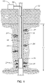
- Figure 1 illustrates an exemplary matrix acidizing operation being conducted within a wellbore and which incorporates a matrix acidizing monitoring system in accordance with the present invention.
- Wellbore 10 has been drilled from the surface 12 down through the earth 14 to a hydrocarbon-bearing formation 16 within which it is desired to conduct matrix acidizing.
- the formation 16 has a vertical formation interval 17.
- a tool string 18 has been run into the wellbore 10 from the surface 12 and carries a bottom hole assembly 20 in the form of a matrix acidizing tool.
- the bottom hole assembly 20 tool is preferably a metal cylinder having temperature and pressure sensors on its outer surface and connected for signal transmission to the surface, as will be described.
- the tool string 18 is made up of coiled tubing, of a type known in the art, which can be injected into the wellbore 10.
- An annulus 22 is formed radially between the tool string 18/bottom hole assembly 20 and the inner wall of the wellbore 10.
- acid is pumped down the tool string 18 and is injected under pressure through the matrix acidizing bottom hole assembly 20 into the formation 16.
- the injected acid will enter wormholes 24.
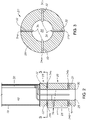
- FIGS 2 and 3 illustrate an exemplary bottom hole assembly 20 in greater detail.
- the exemplary bottom hole assembly 20 includes a generally cylindrical tool body 26 which defines a central axial passage 28 along its length.
- a nozzle 30 is formed on the distal end of the tool body 26 to allow acid injected down the tool string 18 to enter the formation 16. It should be noted that the figures depict a simplified tool having only a single nozzle 30. In practice, the bottom hole assembly 20 might have multiple nozzles or openings that allow acid to be dispersed in multiple locations and in multiple directions.
- Radial passages 32 are drilled through the tool body 26 from the central axial passage 28 to the radial exterior of the tool body 26.
- a sensor array 33 is provided proximate the lower end of the tool string 18 and preferably upon the tool body 26 of the bottom hole assembly 20.
- the sensor array 33 includes multiple sensors 34 which are divided into two sets of sensors 34a, 34b.
- the first set of sensors 34a is axially separated from the second set of sensors 34b along the length of the tool body 26 by a length ("x")(see Fig. 2 ).
- Each sensor 34 is preferably located at the radially outermost portion of each passage 32.
- the sensors 34 are transducers that are capable of detecting temperature and generating a signal indicative of the detected temperature.
- one or more of the sensors 34 are capable of detecting pressure. It is currently preferred that sensors 34 be spaced angularly about the circumference of the tool body 22 in order to obtain sensed parameters from multiple radial directions around the tool body 22. In the depicted embodiment, the sensors 34 are located approximately 90 degrees apart from one another about the circumference of the tool body 22ln the depicted embodiment, there are eight sensors 34. However, there may be more or fewer than eight, as desired.
- the conduit 38 comprises a conductor known in the industry as tubewire, which can be disposed within the coiled tubing to provide a Telecoil conductive system for data/power.
- tubewire refers to a tube which may or may not encapsulate a conductor or other communication means, such as, for example, the tubewire manufactured by Canada Tech Corporation of Calgary, Canada.
- the tubewire may encapsulate one or more fiber optic cables which are used to conduct signals generated by sensors 34 that are in the form of fiber optic sensors.
- the tubewire may consist of multiple tubes and may be concentric or may be coated on the outside with plastic or rubber.
- the conduit 38 extends to surface-based signal processing equipment at the surface 12.
- Fig. 1 illustrates exemplary surface-based equipment to which the conduit 38 might be routed.
- the conduit 38 is operably interconnected with a signal processor 40 of known type that can analyze and in some cases, record and/or display representations of the sensed temperature and/or pressure parameters.
- Suitable signal processing software of a type known in the art can be used to process, record and/or display signals received from the sensors 34.
- the surface-based signal processor 40 includes a fiber optic signal processor.
- a typical fiber optic signal processor would include an optical time-domain reflectometer (OTDR) which is capable of transmitting optical pulses into the fibers and analyzing the light that is returned, reflected or scattered therein. Changes in an index of refraction in the optic fiber can define scatter or reflection points.
- the signal processor 40 can include signal processing software for generating a signal or data representative of the measured conditions.
- the first set of sensors 34a is operable to detect at least one matrix acidizing operational parameter at a first time while the second set of sensors 34b is operable to detect the same at least one matrix acidizing operational parameter at a second time that is after the first time.
- the difference between the first and second time is based upon the rate of movement of the sensor array 33 within the formation 16 relative to a particular point of interest.
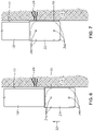
- Figures 6 and 7 illustrates a bottom hole assembly 20 being moved within the wellbore 10 past a point 50 within the formation 16 at which it is desired to detect at least one matrix acidizing operational parameter.
- the first set of sensors 34a is located proximate the point 50. In this position, the sensors 34a detect a matrix acidizing operational parameter at the point 50.
- Figure 7 shows the second set of sensors 34b located proximate the point 50.
- the second set of sensors 34b will detect the same matrix acidizing operational parameter(s) as the first set of sensors 34a.
- the first set of sensors 34a detects the parameter(s) at a first time (t1) while the second set of sensors 34b detect the parameter(s) at a second time (t2).
- the rate of movement of the tool string 18 and bottom hole assembly 20 in direction 52 should be coordinated with the timing of detection of the operational parameter(s) by the two sets of sensors 34a, 34b.
- This coordination can be conducted, for example, by the processing equipment 40 is such equipment 40 is provided with control over the rate of movement.
- the processing equipment 40 will compare the operational parameters(s) detected by the first set of sensors 34a to the operational parameters(s) detected by the second set of sensors 34b. Thus, it can be determined whether the operational parameter is increasing, decreasing or neither.
- This manner of measuring operational parameters can be repeated for multiple points or locations along the formation interval 17. Additionally, more than two sets of sensors might be employed to provide further detail about the measured operational parameter.
- the tool string 18 and bottom hole assembly 20 are disposed into the wellbore 10 and advanced until the bottom hole assembly 20 is proximate the formation 16 into which it is desired to perform matrix acidizing.
- packers (not shown) may be set within the annulus 22 in order to isolate the zone into which acid will be released.
- acid is pumped down the tool string 18 which will then flow through the nozzle 30 of the bottom hole assembly 20 and into the wormholes 24 of the formation 16.
- temperature and/or pressure is detected by the sensors 34 and provided to the processing equipment 40 at surface 12.
- the bottom hole assembly 20 might be moved from one location to another within the formation interval 17. Therefore, the sensors 34 will provide temperature and/or pressure readings from different locations within the formation 16.
- the work string 18 is pulled out of the hole at a constant speed that can be calculated depending on the time difference (t f -t s ) and the length of the stimulated zone along the well.
- the time t f may be the time that the matrix acidizing bottom hole assembly 20 has traveled the entire well interval of interest.
- the number of sensors 34 will be dependent on the accuracy of the data acquisition. For instance, a single temperature sensor may not be sufficient for temperature drop data interpretation, as any temperature difference recorded might be due to either axial flow (flow inside the annulus 22) or radial flow (flow between the wellbore 10 and a wormhole 24).
- multiple sensors 34 could accurately identify of a recorded temperature variation is due to axial flow or radial flow. At least two temperature sensors 34 should be installed sufficiently far away from each other such that they capture temperature differences due to radial acid flow. In particular embodiments, the minimum distance between two temperature sensors 34 is greater than the radial diameter of the wormholes. Thus, it is preferred that the sensors 34 are spaced apart from each other on the tool body 22 by a distance that is greater than the diameter of the wormholes 24.
- Theoretical calculations show that the minimum distance between two temperature sensors 34 should be between 4 and 20 meters (13-66 feet), depending upon the reservoir properties (porosity, permeability, wormhole size and shape, geothermal gradient, thermal conductivity, etc.) and well details (shape, dimensions, completion type, etc.).
- the method could be refined by adding temperature sensors between the two end sensors. Adding more temperature sensors in between increases the accuracy of temperature variation measurement.
- other sensor types could be used. For instance, pressure sensors could also be installed.
- the inventors have found that using an array of single-point temperature and pressure sensors at the end of the tool string 18 and pulling them out of the wellbore 10 at a pre-calculated speed has major advantages over DTS technology.
- Second, as the tool string 18 and single point sensors 34 are pulled out of the wellbore 10 after the acid injection has been stopped (at time t ts), the operator brings the tool string 18 back to the surface 12 in a shorter time.
- a DTS fiber and coiled tubing must stay immobile until all data is recorded (usually until time t f ) and then pulled out of the wellbore.
- Systems and method in accordance with the present invention permit the use of robust, durable conduits, such as tubewire/Telecoil technology. These advantages translate to lower operational costs for the matrix acidizing performance evaluation process when an array of single point sensors 34 at the end of the tool string 18 is used. After real-time downhole temperature and pressure data is acquired and interpreted, the acidizing performance can be visualized by knowing how much acid was injected where. This information is useful for understanding how the formation 16 was treated and if more acidizing is necessary to obtain expected acidizing performance.
Landscapes
- Geology (AREA)
- Life Sciences & Earth Sciences (AREA)
- Engineering & Computer Science (AREA)
- Mining & Mineral Resources (AREA)
- Physics & Mathematics (AREA)
- General Life Sciences & Earth Sciences (AREA)
- Fluid Mechanics (AREA)
- Environmental & Geological Engineering (AREA)
- Geochemistry & Mineralogy (AREA)
- Geophysics (AREA)
- Chemical & Material Sciences (AREA)
- Chemical Kinetics & Catalysis (AREA)
- General Chemical & Material Sciences (AREA)
- Testing Or Calibration Of Command Recording Devices (AREA)
- Lubricants (AREA)
- Measuring Fluid Pressure (AREA)
- Investigating Or Analyzing Materials Using Thermal Means (AREA)
- Investigating Or Analysing Materials By Optical Means (AREA)
Applications Claiming Priority (2)
| Application Number | Priority Date | Filing Date | Title |
|---|---|---|---|
| US14/088,966 US9631474B2 (en) | 2013-11-25 | 2013-11-25 | Systems and methods for real-time evaluation of coiled tubing matrix acidizing |
| PCT/US2014/064495 WO2015077046A1 (en) | 2013-11-25 | 2014-11-07 | Systems and methods for real-time evaluation of coiled tubing matrix acidizing |
Publications (3)
| Publication Number | Publication Date |
|---|---|
| EP3074593A1 EP3074593A1 (en) | 2016-10-05 |
| EP3074593A4 EP3074593A4 (en) | 2017-07-19 |
| EP3074593B1 true EP3074593B1 (en) | 2023-01-04 |
Family
ID=53180026
Family Applications (1)
| Application Number | Title | Priority Date | Filing Date |
|---|---|---|---|
| EP14863485.0A Active EP3074593B1 (en) | 2013-11-25 | 2014-11-07 | Systems and methods for real-time evaluation of coiled tubing matrix acidizing |
Country Status (10)
| Country | Link |
|---|---|
| US (1) | US9631474B2 (enExample) |
| EP (1) | EP3074593B1 (enExample) |
| BR (1) | BR112016011852B1 (enExample) |
| CA (1) | CA2929656C (enExample) |
| DK (1) | DK3074593T3 (enExample) |
| NO (1) | NO20160744A1 (enExample) |
| NZ (1) | NZ719409A (enExample) |
| RU (1) | RU2663981C1 (enExample) |
| SA (1) | SA516371158B1 (enExample) |
| WO (1) | WO2015077046A1 (enExample) |
Families Citing this family (6)
| Publication number | Priority date | Publication date | Assignee | Title |
|---|---|---|---|---|
| US9558642B2 (en) * | 2015-04-21 | 2017-01-31 | Vivint, Inc. | Sleep state monitoring |
| US9850714B2 (en) * | 2015-05-13 | 2017-12-26 | Baker Hughes, A Ge Company, Llc | Real time steerable acid tunneling system |
| WO2017074722A1 (en) * | 2015-10-28 | 2017-05-04 | Baker Hughes Incorporated | Real-time data acquisition and interpretation for coiled tubing fluid injection operations |
| US10323471B2 (en) | 2016-03-11 | 2019-06-18 | Baker Hughes, A Ge Company, Llc | Intelligent injector control system, coiled tubing unit having the same, and method |
| CN108691524A (zh) * | 2017-04-05 | 2018-10-23 | 中国石油化工股份有限公司 | 注水井井压动态监测、解析和酸化效果预估方法 |
| US10815774B2 (en) | 2018-01-02 | 2020-10-27 | Baker Hughes, A Ge Company, Llc | Coiled tubing telemetry system and method for production logging and profiling |
Citations (1)
| Publication number | Priority date | Publication date | Assignee | Title |
|---|---|---|---|---|
| US20070289739A1 (en) * | 2006-06-19 | 2007-12-20 | Iain Cooper | Fluid diversion measurement methods and systems |
Family Cites Families (11)
| Publication number | Priority date | Publication date | Assignee | Title |
|---|---|---|---|---|
| US5829520A (en) * | 1995-02-14 | 1998-11-03 | Baker Hughes Incorporated | Method and apparatus for testing, completion and/or maintaining wellbores using a sensor device |
| US6281489B1 (en) * | 1997-05-02 | 2001-08-28 | Baker Hughes Incorporated | Monitoring of downhole parameters and tools utilizing fiber optics |
| AU2003255294A1 (en) * | 2002-08-15 | 2004-03-11 | Sofitech N.V. | Use of distributed temperature sensors during wellbore treatments |
| US6874361B1 (en) * | 2004-01-08 | 2005-04-05 | Halliburton Energy Services, Inc. | Distributed flow properties wellbore measurement system |
| US20070234789A1 (en) * | 2006-04-05 | 2007-10-11 | Gerard Glasbergen | Fluid distribution determination and optimization with real time temperature measurement |
| US9103203B2 (en) * | 2007-03-26 | 2015-08-11 | Schlumberger Technology Corporation | Wireless logging of fluid filled boreholes |
| CA2717593C (en) * | 2008-03-03 | 2015-12-08 | Intelliserv International Holding, Ltd. | Monitoring downhole conditions with drill string distributed measurement system |
| US8269161B2 (en) * | 2008-12-12 | 2012-09-18 | Baker Hughes Incorporated | Apparatus and method for evaluating downhole fluids |
| US8788251B2 (en) * | 2010-05-21 | 2014-07-22 | Schlumberger Technology Corporation | Method for interpretation of distributed temperature sensors during wellbore treatment |
| US8616282B2 (en) * | 2010-06-28 | 2013-12-31 | Schlumberger Technology Corporation | System and method for determining downhole fluid parameters |
| WO2013085479A1 (en) | 2011-12-06 | 2013-06-13 | Schlumberger Canada Limited | Method for interpretation of downhole flow measurement during wellbore treatments |
-
2013
- 2013-11-25 US US14/088,966 patent/US9631474B2/en active Active
-
2014
- 2014-11-07 WO PCT/US2014/064495 patent/WO2015077046A1/en not_active Ceased
- 2014-11-07 RU RU2016125300A patent/RU2663981C1/ru active
- 2014-11-07 DK DK14863485.0T patent/DK3074593T3/da active
- 2014-11-07 BR BR112016011852-9A patent/BR112016011852B1/pt active IP Right Grant
- 2014-11-07 CA CA2929656A patent/CA2929656C/en not_active Expired - Fee Related
- 2014-11-07 NZ NZ71940914A patent/NZ719409A/en not_active IP Right Cessation
- 2014-11-07 EP EP14863485.0A patent/EP3074593B1/en active Active
-
2016
- 2016-05-04 NO NO20160744A patent/NO20160744A1/en unknown
- 2016-05-19 SA SA516371158A patent/SA516371158B1/ar unknown
Patent Citations (1)
| Publication number | Priority date | Publication date | Assignee | Title |
|---|---|---|---|---|
| US20070289739A1 (en) * | 2006-06-19 | 2007-12-20 | Iain Cooper | Fluid diversion measurement methods and systems |
Also Published As
| Publication number | Publication date |
|---|---|
| US20150144331A1 (en) | 2015-05-28 |
| CA2929656A1 (en) | 2015-05-28 |
| US9631474B2 (en) | 2017-04-25 |
| NO20160744A1 (en) | 2016-05-04 |
| RU2663981C1 (ru) | 2018-08-14 |
| DK3074593T3 (da) | 2023-01-30 |
| EP3074593A4 (en) | 2017-07-19 |
| SA516371158B1 (ar) | 2021-09-08 |
| EP3074593A1 (en) | 2016-10-05 |
| CA2929656C (en) | 2019-03-12 |
| WO2015077046A1 (en) | 2015-05-28 |
| NZ719409A (en) | 2019-10-25 |
| BR112016011852B1 (pt) | 2022-06-21 |
| BR112016011852A2 (enExample) | 2017-08-08 |
| RU2016125300A (ru) | 2018-01-09 |
Similar Documents
| Publication | Publication Date | Title |
|---|---|---|
| US9631478B2 (en) | Real-time data acquisition and interpretation for coiled tubing fluid injection operations | |
| EP3074593B1 (en) | Systems and methods for real-time evaluation of coiled tubing matrix acidizing | |
| US10233744B2 (en) | Methods, apparatus, and systems for steam flow profiling | |
| US9075155B2 (en) | Optical fiber based downhole seismic sensor systems and methods | |
| US8251140B2 (en) | Fluid monitoring and flow characterization | |
| RU2577568C1 (ru) | Способ интерпретации измерений скважинного дебита во время скважинной обработки | |
| US10132159B2 (en) | Production logging multi-lateral wells | |
| CA2913794C (en) | Method and system for monitoring and managing fiber cable slack in a coiled tubing | |
| US10815774B2 (en) | Coiled tubing telemetry system and method for production logging and profiling | |
| GB2496863A (en) | Distributed two dimensional fluid sensor | |
| NO348231B1 (en) | Distributed fiber optic monitoring of vibration to generate a noise log to determine characteristics of fluid flow | |
| US20160319661A1 (en) | Using Downhole Strain Measurements to Determine Hydraulic Fracture System Geometry | |
| Sun et al. | Fiber optic distributed sensing technology for real-time monitoring water jet tests: Implications for wellbore integrity diagnostics | |
| WO2017074722A1 (en) | Real-time data acquisition and interpretation for coiled tubing fluid injection operations | |
| US20160265905A1 (en) | Distributed strain monitoring for downhole tools | |
| Carpenter | Distributed acoustic sensing for downhole production and injection profiling | |
| GB2525199A (en) | Method of detecting a fracture or thief zone in a formation and system for detecting |
Legal Events
| Date | Code | Title | Description |
|---|---|---|---|
| PUAI | Public reference made under article 153(3) epc to a published international application that has entered the european phase |
Free format text: ORIGINAL CODE: 0009012 |
|
| 17P | Request for examination filed |
Effective date: 20160525 |
|
| AK | Designated contracting states |
Kind code of ref document: A1 Designated state(s): AL AT BE BG CH CY CZ DE DK EE ES FI FR GB GR HR HU IE IS IT LI LT LU LV MC MK MT NL NO PL PT RO RS SE SI SK SM TR |
|
| AX | Request for extension of the european patent |
Extension state: BA ME |
|
| DAX | Request for extension of the european patent (deleted) | ||
| A4 | Supplementary search report drawn up and despatched |
Effective date: 20170620 |
|
| RIC1 | Information provided on ipc code assigned before grant |
Ipc: E21B 43/25 20060101ALI20170613BHEP Ipc: E21B 47/06 20120101AFI20170613BHEP |
|
| STAA | Information on the status of an ep patent application or granted ep patent |
Free format text: STATUS: EXAMINATION IS IN PROGRESS |
|
| 17Q | First examination report despatched |
Effective date: 20190123 |
|
| GRAP | Despatch of communication of intention to grant a patent |
Free format text: ORIGINAL CODE: EPIDOSNIGR1 |
|
| STAA | Information on the status of an ep patent application or granted ep patent |
Free format text: STATUS: GRANT OF PATENT IS INTENDED |
|
| INTG | Intention to grant announced |
Effective date: 20220704 |
|
| GRAS | Grant fee paid |
Free format text: ORIGINAL CODE: EPIDOSNIGR3 |
|
| RAP3 | Party data changed (applicant data changed or rights of an application transferred) |
Owner name: BAKER HUGHES HOLDINGS LLC |
|
| GRAA | (expected) grant |
Free format text: ORIGINAL CODE: 0009210 |
|
| STAA | Information on the status of an ep patent application or granted ep patent |
Free format text: STATUS: THE PATENT HAS BEEN GRANTED |
|
| AK | Designated contracting states |
Kind code of ref document: B1 Designated state(s): AL AT BE BG CH CY CZ DE DK EE ES FI FR GB GR HR HU IE IS IT LI LT LU LV MC MK MT NL NO PL PT RO RS SE SI SK SM TR |
|
| REG | Reference to a national code |
Ref country code: GB Ref legal event code: FG4D |
|
| REG | Reference to a national code |
Ref country code: CH Ref legal event code: EP |
|
| REG | Reference to a national code |
Ref country code: AT Ref legal event code: REF Ref document number: 1542044 Country of ref document: AT Kind code of ref document: T Effective date: 20230115 |
|
| REG | Reference to a national code |
Ref country code: DE Ref legal event code: R096 Ref document number: 602014086027 Country of ref document: DE |
|
| REG | Reference to a national code |
Ref country code: DK Ref legal event code: T3 Effective date: 20230123 |
|
| REG | Reference to a national code |
Ref country code: IE Ref legal event code: FG4D |
|
| REG | Reference to a national code |
Ref country code: NL Ref legal event code: FP |
|
| REG | Reference to a national code |
Ref country code: LT Ref legal event code: MG9D |
|
| REG | Reference to a national code |
Ref country code: AT Ref legal event code: MK05 Ref document number: 1542044 Country of ref document: AT Kind code of ref document: T Effective date: 20230104 |
|
| P01 | Opt-out of the competence of the unified patent court (upc) registered |
Effective date: 20230526 |
|
| PG25 | Lapsed in a contracting state [announced via postgrant information from national office to epo] |
Ref country code: RS Free format text: LAPSE BECAUSE OF FAILURE TO SUBMIT A TRANSLATION OF THE DESCRIPTION OR TO PAY THE FEE WITHIN THE PRESCRIBED TIME-LIMIT Effective date: 20230104 Ref country code: PT Free format text: LAPSE BECAUSE OF FAILURE TO SUBMIT A TRANSLATION OF THE DESCRIPTION OR TO PAY THE FEE WITHIN THE PRESCRIBED TIME-LIMIT Effective date: 20230504 Ref country code: NO Free format text: LAPSE BECAUSE OF FAILURE TO SUBMIT A TRANSLATION OF THE DESCRIPTION OR TO PAY THE FEE WITHIN THE PRESCRIBED TIME-LIMIT Effective date: 20230404 Ref country code: LV Free format text: LAPSE BECAUSE OF FAILURE TO SUBMIT A TRANSLATION OF THE DESCRIPTION OR TO PAY THE FEE WITHIN THE PRESCRIBED TIME-LIMIT Effective date: 20230104 Ref country code: LT Free format text: LAPSE BECAUSE OF FAILURE TO SUBMIT A TRANSLATION OF THE DESCRIPTION OR TO PAY THE FEE WITHIN THE PRESCRIBED TIME-LIMIT Effective date: 20230104 Ref country code: HR Free format text: LAPSE BECAUSE OF FAILURE TO SUBMIT A TRANSLATION OF THE DESCRIPTION OR TO PAY THE FEE WITHIN THE PRESCRIBED TIME-LIMIT Effective date: 20230104 Ref country code: ES Free format text: LAPSE BECAUSE OF FAILURE TO SUBMIT A TRANSLATION OF THE DESCRIPTION OR TO PAY THE FEE WITHIN THE PRESCRIBED TIME-LIMIT Effective date: 20230104 Ref country code: AT Free format text: LAPSE BECAUSE OF FAILURE TO SUBMIT A TRANSLATION OF THE DESCRIPTION OR TO PAY THE FEE WITHIN THE PRESCRIBED TIME-LIMIT Effective date: 20230104 |
|
| PG25 | Lapsed in a contracting state [announced via postgrant information from national office to epo] |
Ref country code: SE Free format text: LAPSE BECAUSE OF FAILURE TO SUBMIT A TRANSLATION OF THE DESCRIPTION OR TO PAY THE FEE WITHIN THE PRESCRIBED TIME-LIMIT Effective date: 20230104 Ref country code: PL Free format text: LAPSE BECAUSE OF FAILURE TO SUBMIT A TRANSLATION OF THE DESCRIPTION OR TO PAY THE FEE WITHIN THE PRESCRIBED TIME-LIMIT Effective date: 20230104 Ref country code: IS Free format text: LAPSE BECAUSE OF FAILURE TO SUBMIT A TRANSLATION OF THE DESCRIPTION OR TO PAY THE FEE WITHIN THE PRESCRIBED TIME-LIMIT Effective date: 20230504 Ref country code: GR Free format text: LAPSE BECAUSE OF FAILURE TO SUBMIT A TRANSLATION OF THE DESCRIPTION OR TO PAY THE FEE WITHIN THE PRESCRIBED TIME-LIMIT Effective date: 20230405 Ref country code: FI Free format text: LAPSE BECAUSE OF FAILURE TO SUBMIT A TRANSLATION OF THE DESCRIPTION OR TO PAY THE FEE WITHIN THE PRESCRIBED TIME-LIMIT Effective date: 20230104 |
|
| REG | Reference to a national code |
Ref country code: DE Ref legal event code: R097 Ref document number: 602014086027 Country of ref document: DE |
|
| PG25 | Lapsed in a contracting state [announced via postgrant information from national office to epo] |
Ref country code: SM Free format text: LAPSE BECAUSE OF FAILURE TO SUBMIT A TRANSLATION OF THE DESCRIPTION OR TO PAY THE FEE WITHIN THE PRESCRIBED TIME-LIMIT Effective date: 20230104 Ref country code: RO Free format text: LAPSE BECAUSE OF FAILURE TO SUBMIT A TRANSLATION OF THE DESCRIPTION OR TO PAY THE FEE WITHIN THE PRESCRIBED TIME-LIMIT Effective date: 20230104 Ref country code: EE Free format text: LAPSE BECAUSE OF FAILURE TO SUBMIT A TRANSLATION OF THE DESCRIPTION OR TO PAY THE FEE WITHIN THE PRESCRIBED TIME-LIMIT Effective date: 20230104 Ref country code: CZ Free format text: LAPSE BECAUSE OF FAILURE TO SUBMIT A TRANSLATION OF THE DESCRIPTION OR TO PAY THE FEE WITHIN THE PRESCRIBED TIME-LIMIT Effective date: 20230104 |
|
| PLBE | No opposition filed within time limit |
Free format text: ORIGINAL CODE: 0009261 |
|
| STAA | Information on the status of an ep patent application or granted ep patent |
Free format text: STATUS: NO OPPOSITION FILED WITHIN TIME LIMIT |
|
| PG25 | Lapsed in a contracting state [announced via postgrant information from national office to epo] |
Ref country code: SK Free format text: LAPSE BECAUSE OF FAILURE TO SUBMIT A TRANSLATION OF THE DESCRIPTION OR TO PAY THE FEE WITHIN THE PRESCRIBED TIME-LIMIT Effective date: 20230104 |
|
| 26N | No opposition filed |
Effective date: 20231005 |
|
| PG25 | Lapsed in a contracting state [announced via postgrant information from national office to epo] |
Ref country code: SI Free format text: LAPSE BECAUSE OF FAILURE TO SUBMIT A TRANSLATION OF THE DESCRIPTION OR TO PAY THE FEE WITHIN THE PRESCRIBED TIME-LIMIT Effective date: 20230104 |
|
| REG | Reference to a national code |
Ref country code: DE Ref legal event code: R119 Ref document number: 602014086027 Country of ref document: DE |
|
| REG | Reference to a national code |
Ref country code: CH Ref legal event code: PL |
|
| PG25 | Lapsed in a contracting state [announced via postgrant information from national office to epo] |
Ref country code: MC Free format text: LAPSE BECAUSE OF FAILURE TO SUBMIT A TRANSLATION OF THE DESCRIPTION OR TO PAY THE FEE WITHIN THE PRESCRIBED TIME-LIMIT Effective date: 20230104 |
|
| PG25 | Lapsed in a contracting state [announced via postgrant information from national office to epo] |
Ref country code: LU Free format text: LAPSE BECAUSE OF NON-PAYMENT OF DUE FEES Effective date: 20231107 |
|
| PG25 | Lapsed in a contracting state [announced via postgrant information from national office to epo] |
Ref country code: CH Free format text: LAPSE BECAUSE OF NON-PAYMENT OF DUE FEES Effective date: 20231130 |
|
| PG25 | Lapsed in a contracting state [announced via postgrant information from national office to epo] |
Ref country code: MC Free format text: LAPSE BECAUSE OF FAILURE TO SUBMIT A TRANSLATION OF THE DESCRIPTION OR TO PAY THE FEE WITHIN THE PRESCRIBED TIME-LIMIT Effective date: 20230104 Ref country code: LU Free format text: LAPSE BECAUSE OF NON-PAYMENT OF DUE FEES Effective date: 20231107 Ref country code: CH Free format text: LAPSE BECAUSE OF NON-PAYMENT OF DUE FEES Effective date: 20231130 |
|
| REG | Reference to a national code |
Ref country code: BE Ref legal event code: MM Effective date: 20231130 |
|
| REG | Reference to a national code |
Ref country code: IE Ref legal event code: MM4A |
|
| PG25 | Lapsed in a contracting state [announced via postgrant information from national office to epo] |
Ref country code: IE Free format text: LAPSE BECAUSE OF NON-PAYMENT OF DUE FEES Effective date: 20231107 Ref country code: DE Free format text: LAPSE BECAUSE OF NON-PAYMENT OF DUE FEES Effective date: 20240601 |
|
| PG25 | Lapsed in a contracting state [announced via postgrant information from national office to epo] |
Ref country code: BE Free format text: LAPSE BECAUSE OF NON-PAYMENT OF DUE FEES Effective date: 20231130 |
|
| PG25 | Lapsed in a contracting state [announced via postgrant information from national office to epo] |
Ref country code: FR Free format text: LAPSE BECAUSE OF NON-PAYMENT OF DUE FEES Effective date: 20231130 |
|
| PG25 | Lapsed in a contracting state [announced via postgrant information from national office to epo] |
Ref country code: IE Free format text: LAPSE BECAUSE OF NON-PAYMENT OF DUE FEES Effective date: 20231107 Ref country code: FR Free format text: LAPSE BECAUSE OF NON-PAYMENT OF DUE FEES Effective date: 20231130 Ref country code: DE Free format text: LAPSE BECAUSE OF NON-PAYMENT OF DUE FEES Effective date: 20240601 Ref country code: BE Free format text: LAPSE BECAUSE OF NON-PAYMENT OF DUE FEES Effective date: 20231130 |
|
| PG25 | Lapsed in a contracting state [announced via postgrant information from national office to epo] |
Ref country code: BG Free format text: LAPSE BECAUSE OF FAILURE TO SUBMIT A TRANSLATION OF THE DESCRIPTION OR TO PAY THE FEE WITHIN THE PRESCRIBED TIME-LIMIT Effective date: 20230104 |
|
| PG25 | Lapsed in a contracting state [announced via postgrant information from national office to epo] |
Ref country code: BG Free format text: LAPSE BECAUSE OF FAILURE TO SUBMIT A TRANSLATION OF THE DESCRIPTION OR TO PAY THE FEE WITHIN THE PRESCRIBED TIME-LIMIT Effective date: 20230104 |
|
| PGFP | Annual fee paid to national office [announced via postgrant information from national office to epo] |
Ref country code: DK Payment date: 20241022 Year of fee payment: 11 |
|
| PGFP | Annual fee paid to national office [announced via postgrant information from national office to epo] |
Ref country code: GB Payment date: 20241023 Year of fee payment: 11 |
|
| PGFP | Annual fee paid to national office [announced via postgrant information from national office to epo] |
Ref country code: IT Payment date: 20241022 Year of fee payment: 11 |
|
| PG25 | Lapsed in a contracting state [announced via postgrant information from national office to epo] |
Ref country code: CY Free format text: LAPSE BECAUSE OF FAILURE TO SUBMIT A TRANSLATION OF THE DESCRIPTION OR TO PAY THE FEE WITHIN THE PRESCRIBED TIME-LIMIT; INVALID AB INITIO Effective date: 20141107 |
|
| PG25 | Lapsed in a contracting state [announced via postgrant information from national office to epo] |
Ref country code: HU Free format text: LAPSE BECAUSE OF FAILURE TO SUBMIT A TRANSLATION OF THE DESCRIPTION OR TO PAY THE FEE WITHIN THE PRESCRIBED TIME-LIMIT; INVALID AB INITIO Effective date: 20141107 |
|
| PGFP | Annual fee paid to national office [announced via postgrant information from national office to epo] |
Ref country code: NL Payment date: 20251022 Year of fee payment: 12 |
|
| PG25 | Lapsed in a contracting state [announced via postgrant information from national office to epo] |
Ref country code: TR Free format text: LAPSE BECAUSE OF FAILURE TO SUBMIT A TRANSLATION OF THE DESCRIPTION OR TO PAY THE FEE WITHIN THE PRESCRIBED TIME-LIMIT Effective date: 20230104 |