EP3074469B1 - Submikrometergrosse aluminiumhaltige teilchen - Google Patents
Submikrometergrosse aluminiumhaltige teilchen Download PDFInfo
- Publication number
- EP3074469B1 EP3074469B1 EP14816143.3A EP14816143A EP3074469B1 EP 3074469 B1 EP3074469 B1 EP 3074469B1 EP 14816143 A EP14816143 A EP 14816143A EP 3074469 B1 EP3074469 B1 EP 3074469B1
- Authority
- EP
- European Patent Office
- Prior art keywords
- reaction
- chemical element
- stream
- reaction stream
- chamber
- Prior art date
- Legal status (The legal status is an assumption and is not a legal conclusion. Google has not performed a legal analysis and makes no representation as to the accuracy of the status listed.)
- Active
Links
Images


Classifications
-
- C—CHEMISTRY; METALLURGY
- C01—INORGANIC CHEMISTRY
- C01B—NON-METALLIC ELEMENTS; COMPOUNDS THEREOF; METALLOIDS OR COMPOUNDS THEREOF NOT COVERED BY SUBCLASS C01C
- C01B33/00—Silicon; Compounds thereof
- C01B33/02—Silicon
- C01B33/021—Preparation
- C01B33/027—Preparation by decomposition or reduction of gaseous or vaporised silicon compounds other than silica or silica-containing material
- C01B33/029—Preparation by decomposition or reduction of gaseous or vaporised silicon compounds other than silica or silica-containing material by decomposition of monosilane
-
- B—PERFORMING OPERATIONS; TRANSPORTING
- B01—PHYSICAL OR CHEMICAL PROCESSES OR APPARATUS IN GENERAL
- B01J—CHEMICAL OR PHYSICAL PROCESSES, e.g. CATALYSIS OR COLLOID CHEMISTRY; THEIR RELEVANT APPARATUS
- B01J12/00—Chemical processes in general for reacting gaseous media with gaseous media; Apparatus specially adapted therefor
- B01J12/005—Chemical processes in general for reacting gaseous media with gaseous media; Apparatus specially adapted therefor carried out at high temperatures, e.g. by pyrolysis
-
- B—PERFORMING OPERATIONS; TRANSPORTING
- B01—PHYSICAL OR CHEMICAL PROCESSES OR APPARATUS IN GENERAL
- B01J—CHEMICAL OR PHYSICAL PROCESSES, e.g. CATALYSIS OR COLLOID CHEMISTRY; THEIR RELEVANT APPARATUS
- B01J13/00—Colloid chemistry, e.g. the production of colloidal materials or their solutions, not otherwise provided for; Making microcapsules or microballoons
- B01J13/02—Making microcapsules or microballoons
- B01J13/04—Making microcapsules or microballoons by physical processes, e.g. drying, spraying
-
- B—PERFORMING OPERATIONS; TRANSPORTING
- B01—PHYSICAL OR CHEMICAL PROCESSES OR APPARATUS IN GENERAL
- B01J—CHEMICAL OR PHYSICAL PROCESSES, e.g. CATALYSIS OR COLLOID CHEMISTRY; THEIR RELEVANT APPARATUS
- B01J19/00—Chemical, physical or physico-chemical processes in general; Their relevant apparatus
- B01J19/08—Processes employing the direct application of electric or wave energy, or particle radiation; Apparatus therefor
- B01J19/081—Processes employing the direct application of electric or wave energy, or particle radiation; Apparatus therefor employing particle radiation or gamma-radiation
-
- B—PERFORMING OPERATIONS; TRANSPORTING
- B01—PHYSICAL OR CHEMICAL PROCESSES OR APPARATUS IN GENERAL
- B01J—CHEMICAL OR PHYSICAL PROCESSES, e.g. CATALYSIS OR COLLOID CHEMISTRY; THEIR RELEVANT APPARATUS
- B01J19/00—Chemical, physical or physico-chemical processes in general; Their relevant apparatus
- B01J19/08—Processes employing the direct application of electric or wave energy, or particle radiation; Apparatus therefor
- B01J19/12—Processes employing the direct application of electric or wave energy, or particle radiation; Apparatus therefor employing electromagnetic waves
- B01J19/121—Coherent waves, e.g. laser beams
-
- B—PERFORMING OPERATIONS; TRANSPORTING
- B01—PHYSICAL OR CHEMICAL PROCESSES OR APPARATUS IN GENERAL
- B01J—CHEMICAL OR PHYSICAL PROCESSES, e.g. CATALYSIS OR COLLOID CHEMISTRY; THEIR RELEVANT APPARATUS
- B01J19/00—Chemical, physical or physico-chemical processes in general; Their relevant apparatus
- B01J19/24—Stationary reactors without moving elements inside
-
- B—PERFORMING OPERATIONS; TRANSPORTING
- B01—PHYSICAL OR CHEMICAL PROCESSES OR APPARATUS IN GENERAL
- B01J—CHEMICAL OR PHYSICAL PROCESSES, e.g. CATALYSIS OR COLLOID CHEMISTRY; THEIR RELEVANT APPARATUS
- B01J4/00—Feed or outlet devices; Feed or outlet control devices
- B01J4/001—Feed or outlet devices as such, e.g. feeding tubes
-
- B—PERFORMING OPERATIONS; TRANSPORTING
- B01—PHYSICAL OR CHEMICAL PROCESSES OR APPARATUS IN GENERAL
- B01J—CHEMICAL OR PHYSICAL PROCESSES, e.g. CATALYSIS OR COLLOID CHEMISTRY; THEIR RELEVANT APPARATUS
- B01J4/00—Feed or outlet devices; Feed or outlet control devices
- B01J4/001—Feed or outlet devices as such, e.g. feeding tubes
- B01J4/002—Nozzle-type elements
-
- B—PERFORMING OPERATIONS; TRANSPORTING
- B01—PHYSICAL OR CHEMICAL PROCESSES OR APPARATUS IN GENERAL
- B01J—CHEMICAL OR PHYSICAL PROCESSES, e.g. CATALYSIS OR COLLOID CHEMISTRY; THEIR RELEVANT APPARATUS
- B01J4/00—Feed or outlet devices; Feed or outlet control devices
- B01J4/001—Feed or outlet devices as such, e.g. feeding tubes
- B01J4/004—Sparger-type elements
-
- C—CHEMISTRY; METALLURGY
- C01—INORGANIC CHEMISTRY
- C01B—NON-METALLIC ELEMENTS; COMPOUNDS THEREOF; METALLOIDS OR COMPOUNDS THEREOF NOT COVERED BY SUBCLASS C01C
- C01B32/00—Carbon; Compounds thereof
- C01B32/90—Carbides
- C01B32/914—Carbides of single elements
- C01B32/956—Silicon carbide
-
- C—CHEMISTRY; METALLURGY
- C01—INORGANIC CHEMISTRY
- C01B—NON-METALLIC ELEMENTS; COMPOUNDS THEREOF; METALLOIDS OR COMPOUNDS THEREOF NOT COVERED BY SUBCLASS C01C
- C01B32/00—Carbon; Compounds thereof
- C01B32/90—Carbides
- C01B32/914—Carbides of single elements
- C01B32/956—Silicon carbide
- C01B32/963—Preparation from compounds containing silicon
-
- C—CHEMISTRY; METALLURGY
- C01—INORGANIC CHEMISTRY
- C01B—NON-METALLIC ELEMENTS; COMPOUNDS THEREOF; METALLOIDS OR COMPOUNDS THEREOF NOT COVERED BY SUBCLASS C01C
- C01B33/00—Silicon; Compounds thereof
- C01B33/02—Silicon
- C01B33/021—Preparation
- C01B33/027—Preparation by decomposition or reduction of gaseous or vaporised silicon compounds other than silica or silica-containing material
-
- C—CHEMISTRY; METALLURGY
- C09—DYES; PAINTS; POLISHES; NATURAL RESINS; ADHESIVES; COMPOSITIONS NOT OTHERWISE PROVIDED FOR; APPLICATIONS OF MATERIALS NOT OTHERWISE PROVIDED FOR
- C09C—TREATMENT OF INORGANIC MATERIALS, OTHER THAN FIBROUS FILLERS, TO ENHANCE THEIR PIGMENTING OR FILLING PROPERTIES ; PREPARATION OF CARBON BLACK ; PREPARATION OF INORGANIC MATERIALS WHICH ARE NO SINGLE CHEMICAL COMPOUNDS AND WHICH ARE MAINLY USED AS PIGMENTS OR FILLERS
- C09C1/00—Treatment of specific inorganic materials other than fibrous fillers; Preparation of carbon black
- C09C1/28—Compounds of silicon
-
- C—CHEMISTRY; METALLURGY
- C09—DYES; PAINTS; POLISHES; NATURAL RESINS; ADHESIVES; COMPOSITIONS NOT OTHERWISE PROVIDED FOR; APPLICATIONS OF MATERIALS NOT OTHERWISE PROVIDED FOR
- C09C—TREATMENT OF INORGANIC MATERIALS, OTHER THAN FIBROUS FILLERS, TO ENHANCE THEIR PIGMENTING OR FILLING PROPERTIES ; PREPARATION OF CARBON BLACK ; PREPARATION OF INORGANIC MATERIALS WHICH ARE NO SINGLE CHEMICAL COMPOUNDS AND WHICH ARE MAINLY USED AS PIGMENTS OR FILLERS
- C09C1/00—Treatment of specific inorganic materials other than fibrous fillers; Preparation of carbon black
- C09C1/28—Compounds of silicon
- C09C1/30—Silicic acid
-
- C—CHEMISTRY; METALLURGY
- C09—DYES; PAINTS; POLISHES; NATURAL RESINS; ADHESIVES; COMPOSITIONS NOT OTHERWISE PROVIDED FOR; APPLICATIONS OF MATERIALS NOT OTHERWISE PROVIDED FOR
- C09C—TREATMENT OF INORGANIC MATERIALS, OTHER THAN FIBROUS FILLERS, TO ENHANCE THEIR PIGMENTING OR FILLING PROPERTIES ; PREPARATION OF CARBON BLACK ; PREPARATION OF INORGANIC MATERIALS WHICH ARE NO SINGLE CHEMICAL COMPOUNDS AND WHICH ARE MAINLY USED AS PIGMENTS OR FILLERS
- C09C1/00—Treatment of specific inorganic materials other than fibrous fillers; Preparation of carbon black
- C09C1/28—Compounds of silicon
- C09C1/30—Silicic acid
- C09C1/3045—Treatment with inorganic compounds
-
- B—PERFORMING OPERATIONS; TRANSPORTING
- B01—PHYSICAL OR CHEMICAL PROCESSES OR APPARATUS IN GENERAL
- B01J—CHEMICAL OR PHYSICAL PROCESSES, e.g. CATALYSIS OR COLLOID CHEMISTRY; THEIR RELEVANT APPARATUS
- B01J2219/00—Chemical, physical or physico-chemical processes in general; Their relevant apparatus
- B01J2219/00049—Controlling or regulating processes
- B01J2219/00051—Controlling the temperature
- B01J2219/00139—Controlling the temperature using electromagnetic heating
-
- B—PERFORMING OPERATIONS; TRANSPORTING
- B01—PHYSICAL OR CHEMICAL PROCESSES OR APPARATUS IN GENERAL
- B01J—CHEMICAL OR PHYSICAL PROCESSES, e.g. CATALYSIS OR COLLOID CHEMISTRY; THEIR RELEVANT APPARATUS
- B01J2219/00—Chemical, physical or physico-chemical processes in general; Their relevant apparatus
- B01J2219/08—Processes employing the direct application of electric or wave energy, or particle radiation; Apparatus therefor
- B01J2219/0873—Materials to be treated
- B01J2219/0875—Gas
-
- C—CHEMISTRY; METALLURGY
- C01—INORGANIC CHEMISTRY
- C01P—INDEXING SCHEME RELATING TO STRUCTURAL AND PHYSICAL ASPECTS OF SOLID INORGANIC COMPOUNDS
- C01P2004/00—Particle morphology
- C01P2004/60—Particles characterised by their size
- C01P2004/62—Submicrometer sized, i.e. from 0.1-1 micrometer
-
- C—CHEMISTRY; METALLURGY
- C01—INORGANIC CHEMISTRY
- C01P—INDEXING SCHEME RELATING TO STRUCTURAL AND PHYSICAL ASPECTS OF SOLID INORGANIC COMPOUNDS
- C01P2004/00—Particle morphology
- C01P2004/60—Particles characterised by their size
- C01P2004/64—Nanometer sized, i.e. from 1-100 nanometer
-
- C—CHEMISTRY; METALLURGY
- C01—INORGANIC CHEMISTRY
- C01P—INDEXING SCHEME RELATING TO STRUCTURAL AND PHYSICAL ASPECTS OF SOLID INORGANIC COMPOUNDS
- C01P2004/00—Particle morphology
- C01P2004/80—Particles consisting of a mixture of two or more inorganic phases
- C01P2004/82—Particles consisting of a mixture of two or more inorganic phases two phases having the same anion, e.g. both oxidic phases
- C01P2004/84—Particles consisting of a mixture of two or more inorganic phases two phases having the same anion, e.g. both oxidic phases one phase coated with the other
- C01P2004/86—Thin layer coatings, i.e. the coating thickness being less than 0.1 time the particle radius
Definitions
- the present invention relates to a method of manufacturing multilayer particles (typically a core layer covered with a top layer), typically by laser pyrolysis. It also relates to an associated device.
- Such a method allows for example a user to manufacture submicron particles of silicon or silicon carbide each coated with a layer of aluminum or aluminum oxide
- the whole is heated to a moderate temperature, possibly under pressure, without leading to the melting temperature ("sintering" process), to obtain a dense nanostructured material.
- the document US 4,505,720 A describes particles having a silicon carbide core covered with a layer.
- the particles according to this document have a core which comprises silicon in oxidized form.
- the document US 4 424 066 A discloses particles coated with a layer comprising aluminum.
- the particles according to this document have a core which comprises silicon in oxidized form.
- the document "Alumina surface modification of silicon nitride for colloidal processing" by Luther at al. discloses particles coated with a layer comprising aluminum.
- the particles according to this document have a core which comprises silicon in oxidized form.
- the document US 2009/026421 A1 discloses a process for making nanoparticles.
- a complementary chemical element is introduced by injectors before the interaction zone of the reagents with the laser, and with a different flow direction (approximately 45 °) with respect to the direction of the reaction flow leaving the conduit.
- the particles according to this document have a core which comprises silicon in oxidized form.
- the document US 2010/221544 A1 does not describe a method or device by laser pyrolysis, but rather microwave.
- the particles according to this document have a core which comprises silicon in oxidized form.
- WO 01/32799 describes a method of laser pyrolysis. This document describes the manufacture of silicate aluminum particles (mixed Si, O and Al atoms).
- the particles manufactured are preferably submicron particles, that is to say particles whose diameter is less than 1000 nanometers, preferably between 1 nanometer and 1000 nanometers.
- the submicron particles are nanometric particles, that is to say particles whose diameter is less than 100 nanometers, preferably between 1 nanometer and 100 nanometers.
- diameter of a particle is meant the distance connecting the two points of this particle furthest apart from each other (for example the length in the case of a rod-shaped particle).
- the core diameter of a particle means the distance connecting the two points of the heart more distant from each other.
- the diameter of the layer comprising the second chemical element means the outer diameter that is to say the distance connecting the two points of this layer furthest apart from each other.
- Each reaction stream is preferably free of oxidizing agent the first chemical element, and the particle cores preferably comprise the first chemical element in non-oxidized form.
- oxidizing agent arranged to oxidize the first chemical element
- the second element layer protects the core from oxidation, and keeps the first element in a non-oxidized state, leaving more choice for the possible uses of cheaper particles. This preserves the first element of the unoxidized core for new uses of non-oxidized particles and does not have to apply a treatment to reduce the oxygen content.
- such a method according to the invention allows for example a user to manufacture submicron particles of non-oxidized silicon or unoxidized silicon carbide each coated with a layer of pure or oxidized aluminum.
- An additional parameter taking into account the aggregation of the particles can be introduced in the calculation of the molar ratio.
- the introduction of at least one reaction stream may comprise an introduction of at least one alignment of several reaction streams separated from each other by the confinement gas flow and each comprising the first chemical element and propagating each according to flow direction.
- the radiation beam may propagate along a direction of radiation preferably perpendicular to the flow direction, and the fluxes of each reaction flow alignment may be aligned along an alignment direction perpendicular to the direction of flow. flow and radiation direction.
- the radiation beam may propagate along a radiation direction preferably perpendicular to the flow direction, and each reaction stream may have, in a plane perpendicular to the flow direction, a longitudinally extending section along the direction of flow. a direction of elongation perpendicular to the direction of flow and the direction of radiation.
- the second chemical element can be introduced into the chamber with the first chemical element in each reaction stream before the interaction zone of each reaction stream.
- the first chemical element is preferably introduced into the chamber in the form of silane (SiH 4 ).
- the second element is preferably aluminum. It is preferably introduced in the form of vaporized trimethylaluminium (Al (CH 3 ) 3 ), or generally in the form of a compound of the category of organometallic aluminum.
- the particles are preferably submicron particles, that is to say particles whose diameter (core + layer) is less than 1000 nanometers, preferably between 1 nanometer and 1000 nanometers.
- the submicron particles are nanometric particles, that is to say particles whose diameter (core + layer) is less than 100 nanometers, preferably between 1 nanometer and 100 nanometers.
- the reagent is preferably devoid of agent designed to oxidize the first chemical element.
- the second element injector and the first element injector are preferably arranged together to introduce a number of atoms of the second element with respect to a number of atoms of the first element in a ratio making it possible to reach the desired thickness. for producing the aluminum or aluminum oxide layer.
- the injector of at least one reaction stream may be arranged to introduce into the chamber at least one alignment of several reaction streams separated from each other by the flow of containment gas and each comprising the first chemical element and propagating each according to the flow direction.
- the emitter may be arranged so that the beam of radiation propagates along a direction of radiation preferably perpendicular to the flow direction, and the injector of at least one reaction flow can be arranged so that the flows of each flow alignment of The reaction is aligned along an alignment direction perpendicular to the flow direction and the radiation direction.
- the emitter may be arranged so that the beam of radiation propagates along a direction of radiation preferably perpendicular to the flow direction, and the injector of at least one reaction flow can be arranged so that each stream In a plane perpendicular to the direction of flow, the reaction has a section extending longitudinally along an elongation direction perpendicular to the direction of flow and the direction of radiation.
- the second chemical element injector may be arranged to introduce the second element into the chamber with the first chemical element in each reaction stream before the interaction zone of each reaction stream.
- the second element is preferably aluminum.
- variants of the invention comprising only a selection of characteristics described subsequently isolated from the other characteristics described (even if this selection is isolated within a sentence comprising these other characteristics), if this selection of characteristics is sufficient to confer a technical advantage or to differentiate the invention from the state of the prior art.
- This selection includes at least one feature of preference functional without structural details, or with only a part of the structural details if this part alone is sufficient to confer a technical advantage or to differentiate the invention from the state of the prior art.
- This first device embodiment 9 for producing by laser pyrolysis of the particles 10 comprises a source 4 of reagent.
- the reagent preferably comprises at least one reaction gas and / or at least one reaction liquid in aerosol form.
- the reagent comprises a first chemical element.
- the first chemical element is preferably a metal (preferably from iron, aluminum, titanium) or a metalloid (from boron, silicon, germanium, arsenic, antimony, tellurium, Polonium). More specifically, the first chemical element in the reagent is preferably silicon, preferably in the form of SiH 4 .
- the reagent is preferably a reaction gas (typically SiH 4 gas or SiH 4 + C 2 H 2 or SiH 4 + C 2 H 4 or SiH 4 + CH 4 gas).
- the device 9 further comprises a reaction chamber 8 (delimited preferably by stainless steel walls) connected to the source 4 of reagent.
- the reaction chamber 8 is filled with an atmosphere of neutral gas (among helium, argon, krypton, xenon, nitrogen or a mixture), preferably argon or nitrogen.
- neutral gas among helium, argon, krypton, xenon, nitrogen or a mixture
- a reagent injector 5 is arranged to introduce into the chamber 8 and from the source 4 of reagent, at least one reaction stream 1, 100, 101, 102, 103, 104, 105, 106, each reaction stream. propagating in an identical flow direction 11 for all the reaction flows and in a reaction flow zone 6 by reaction flow.
- a transmitter 19 (typically a LASER source) of a radiation beam 3 (typically a laser beam, preferably of area between 30 mm 2 and 3000 mm 2 in section perpendicular to the direction 12, width along the direction 13, 18 preferably between 2 and 5 cm, wavelength between 9 microns and 11 microns, preferably 10.6 microns for SiH 4 and power between 50 and 5000 watts and frequency between 10000 and 100000 Hz) is arranged to project the radiation beam 3 through the reaction chamber 8 so that this beam 3 is in intersection, in an interaction zone 14 by zone 6 of reaction flow, with each reaction flow zone 6 so as to form in each reaction stream particle cores comprising the first chemical element.
- a radiation beam 3 typically a laser beam, preferably of area between 30 mm 2 and 3000 mm 2 in section perpendicular to the direction 12, width along the direction 13, 18 preferably between 2 and 5 cm, wavelength between 9 microns and 11 microns, preferably 10.6 microns for SiH 4 and power between 50 and 5000 watts and
- the beam 3 is shaped by an optical system to give it a section preferably rectangular (but could also be elliptical) and preferably vertically focused (ie whose area decreases with the progression of the beam 3 in the direction of radiation 12 ), as described in the documents FR 2 894 493 and FR 2,877,591 .
- the beam 3 enters the chamber 8 through a window 23 of ZnSe and leaves the chamber 8 through another window 24 ZnSe before being stopped by a calorimeter 25 non-reflective ("beam stopper").
- the device 9 further comprises a source of a second chemical element.
- the second chemical element is preferably aluminum injected in the form of trimethylaluminium (or TMA, of chemical formula Al (CH 3 ) 3 , or generally in the form of a compound of the category of organometallic aluminum) heated and vaporized preferably in a neutral gas such as Argon.
- a second element injector is arranged to introduce into the chamber of reaction 8, the second chemical element from the second element source so that the second chemical element is able to interact in the chamber 8 with each reaction stream 1, 100 101, 102, 103, 104, 105, 106 of in order to cover the cores of particles 15 with a layer 16 comprising the second chemical element.
- the reagent in the source 4 and injected into the chamber 8 is devoid of oxidizing agent arranged to oxidize the first chemical element.
- agent designed to oxidize the first chemical element also called “oxidizing agent of the first chemical element”
- the reagent for example a gas of SiH 4 , optionally mixed with C 2 H 2 or C 2 H 4 or CH 4
- the reagent in the source 4 and injected into the chamber 8 is devoid of oxygen atom.
- the injector (5, 21 and / or 22) of the second element and the injector 5 of the first element are within the device 9 arranged together (by their flow rate and their proportions of the various gases that may be mixed, such as SiH 4 for the injector 5, argon or nitrogen for the injector 21 and C 2 H 2 , C 2 H 4 , CH 4 for the injector 5 and / or 21 and / or 22) for introducing into the reaction chamber 8 per unit of time (typically per minute) a number of atoms of the second element relative to a number of atoms of the first element in a selected ratio to achieve the desired thickness of the layer 16.
- the various gases such as SiH 4 for the injector 5, argon or nitrogen for the injector 21 and C 2 H 2 , C 2 H 4 , CH 4 for the injector 5 and / or 21 and / or 22
- the second element injector (5, 21 and / or 22) and the first element injector 5 are within the device 9 arranged together to introduce the desired molar ratio between the second and the first element.
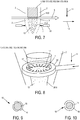
- the device 9 further comprises a source 20 of containment gas comprising a confinement gas and a confinement gas injector 21 arranged to introduce into the reaction chamber 8, before (with respect to flow direction 11) the zone of interaction 14 of each reaction stream, a confinement gas flow 2 (preferably common to all the reaction streams) surrounding each reaction stream 1, 100 101, 102, 103, 104, 105, 106 (more precisely in contact with each reaction stream 1, 100, 101, 102, 103, 104, 105, 106 all around each reaction stream 1, 100, 101, 102, 103, 104, 105, 106 at least from 1 injection of the reagent into the chamber 8 to the interaction zone 14 of each reaction stream, this periphery being defined along a closed line contained in a plane perpendicular to the flow direction 11) and propagating in the direction of flow 11.
- a source 20 of containment gas comprising a confinement gas and a confinement gas injector 21 arranged to introduce into the reaction chamber 8, before (with respect to flow direction 11) the zone of
- the transmitter 19 is arranged so that the radiation beam 3 propagates along a radiation direction 12 perpendicular to the flow direction 11.
- the injector 5 of at least one reaction stream 1, 100, 101, 102, 103, 104, 105, 106 is arranged so that each reaction stream 1, 100, 101, 102, 103, 104, 105, 106 has, in a plane perpendicular to the flow direction 11, a section that can extend longitudinally along an elongation direction 13 perpendicular to the direction of flow 11 and to the direction radiation 12.
- the reagent injector 5 is arranged to introduce into the chamber 8, and from the source 4 of reagent, a single reaction stream 1 propagating in the direction of flow 11 in a zone 6 of the reaction stream.
- the section of the injector 5 is typically an oval 4 mm deep along the direction 12 and 2 cm wide along the direction 13.
- the injector 5 of at least one reaction stream is arranged to introduce into the chamber 8 and from the source 4 of reagent, an alignment of several reaction streams 101, 102, 103 separated from each other by the flow of containment gas 2 and each comprising the first chemical element and propagating each according to the flow direction 11.
- Each stream 101, 102 or 103 propagates along the flow direction 11 in a zone 6 of its own reaction flow.
- the injector 5 of at least one reaction flow 101, 102, 103 is arranged so that, within the flow alignment 101, 102, 103, the different reaction flows 101, 102, 103 are aligned along an alignment direction 18 perpendicular to the flow direction 11 and to the radiation direction 12.
- the injector 5 is subdivided into a plurality of injection nozzles 201, 202, 203 (a jet by reaction flow).
- Each nozzle has a section which is typically a disk, oval or oblong 3 mm deep along the direction 12 and 4 mm wide along the direction 13, 18.
- the number of reaction streams 101, 102, 103 and nozzles 201, 202, 203 are not limited to three at all, we could have many more, this number depending on the width of the laser spot which can range from 2 to 5 cm or more.
- the injector 5 of at least one reaction stream is arranged to introduce into the chamber 8 several reaction streams 1, 100, separated from each other by the flow of confinement gas 2 and each comprising the first chemical element and propagating each according to the flow direction 11.
- the reagent injector 5 is arranged to introduce into the chamber 8 and from the source 4 of reagent, several reaction flows 1, 100, each flow 1, 100 propagating in the direction of flow 11 in a zone 6. reaction flow of its own. These flows 1, 100 are spaced in the direction of radiation 12.
- the losses by absorption of the beam 3 by the reaction flow 1 are compensated by the focusing (or "convergence") of the beam 3 so that the incident power density of the beam 3 on each stream 1 or 100 is identical for all the flows 1, 100 as described in the document FR 2,877,591 .
- This variant makes it possible to increase the production rate on a single reactor by optimally consuming the laser energy for production.
- the injector 5 of at least one reaction stream is arranged to introduce into the chamber 8 and from the source 4 of reactant a plurality of reaction flow alignments separated from each other by the confinement gas flow 2 and including each the first chemical element and propagating each according to the flow direction 11.
- Each stream 101, 102, 103, 104, 105 or 106 propagates along the flow direction 11 in a zone 6 of its own reaction stream.
- the injector 5 of at least one reaction flow is arranged so that the flows respectively 101, 102, 103 or 104, 104 and 105 (or more precisely their section in a plane perpendicular to the flow direction 11) within each alignment is aligned along an alignment direction 18 perpendicular to the flow direction 11 and the radiation direction 12.
- the flow alignments are spaced apart according to the radiation direction 12.
- the different flow alignments are parallel to each other in the same direction 18.
- the injector 5 is subdivided into a plurality of injection nozzles (a jet by reaction flow). Each nozzle has a section which is typically an oval 3 mm deep along the direction 12 and 4 mm wide along the direction 13, 18.
- the losses by absorption of the beam 3 by the first flux alignment 101, 102, 103 are compensated by the focusing (or "convergence") of the beam 3 so that the incident power density of the beam 3 on each flux alignment 101, 102, 103 or 104, 105, 106 is identical for all flows 101, 102, 103, 104, 105 or 106 according to the principle described in document FR 2,877,591 .
- the second chemical element injector is arranged to introduce the second element in the chamber 8 with the first chemical element in each reaction stream 1, 100, 101, 102, 103, 104, 105, 106 before (relative to flow direction 11) the interaction zone 14 of each reaction flow.
- the second chemical element injector comprises the reagent injector. More exactly, the second chemical element injector and the reagent injector 5 are merged.
- a second embodiment of device 9 according to the invention is strictly identical to the first embodiment of device 9 previously described (regardless of its variant considered among its four variants previously described), apart from the fact that the injector second chemical element is arranged to introduce the second chemical element into the chamber 8 in a gas stream 2 surrounding each reaction stream 1, 100, 101, 102, 103, 104, 105, 106.
- the second chemical element injector is arranged to introduce the second chemical element into the chamber 8 in the confinement gas flow 2 before (with respect to the flow direction 11) the interaction zone 14 of each flow of reaction.
- the second chemical element injector comprises the confinement gas injector 21. More precisely, the second chemical element injector and the confinement gas injector 21 are merged.
- This second embodiment is preferably implemented within the second or fourth variant (comprising one or more flux alignment (s) 101, 102, 103 and 104, 105, 106 of the figures 3 and 6 ) because it maximizes the interaction area between the confinement gas 2 comprising the second chemical element and each reaction stream comprising the first chemical element.
- a third embodiment of device 9 according to the invention is strictly identical to the first embodiment of device 9 previously described (regardless of its variant considered among its four previously described variants), apart from the fact that the injector second chemical element is arranged to introduce the second chemical element into the chamber 8 in a flow of gas 7 surrounding each reaction stream 1, 100, 101, 102, 103, 104, 105, 106.
- the second chemical element injector is arranged to introduce the second chemical element into the chamber 8 in a peripheral gas flow 7 surrounding said reaction stream 1, 100, 101, 102, 103, 104, 105, or 106 and emitted from a plurality of points 17 distributed along a closed curve (typically annular shape of the injector 22) surrounding this stream reaction and arranged to direct the flow of peripheral gas 7 towards this reaction flow.
- a closed curve typically annular shape of the injector 22
- the second chemical element injector is arranged to introduce the second chemical element into the chamber 8 in the peripheral gas flow 7 after (with respect to flow direction 11) the interaction zone 14 of this reaction flow.
- This is particularly interesting because it allows to have a good control (by playing on the power of the beam 3) and a good homogeneity of manufacture of the cores 15 of the particles 10.
- the manufacture of the layers 16 on the cores 15 of the particles does not come not taking energy directly from the beam 3 and thus does not disturb the control that one has on the manufacture of the cores 15. In fact, the manufacture of the layers 16 on the cores 15 of the particles uses the energy of the flame 26 after the interaction zone 14.
- This third embodiment of device 9 comprises means for moving (not shown, including for example a micro-displacement stage) each injector 22 along the flow direction 11 so as to optimize the layer 16 manufactured for the particles 10 .
- the reagent of the reaction streams is devoid of oxidizing agent the first chemical element.
- the particle cores obtained by this method comprise the first chemical element in non-oxidized form.
- the number of atoms introduced per unit of time is in a molar ratio making it possible to attain the desired thickness for the production of a layer 16 of aluminum or of aluminum oxide obtained by oxidation of the aluminum layer .
- the radiation beam 3 propagates along the radiation direction 12 perpendicular to the flow direction 11.
- Each reaction stream has, in a plane perpendicular to the flow direction 11, a section extending longitudinally along the elongation direction 13 perpendicular to the flow direction 11 and to the radiation direction 12.
- the particles thus manufactured fall into a recuperator 27 where they are cooled before being conveyed by gravity and / or suction to a facility using the particles or to a container for storage.
- the second chemical element is introduced into the chamber 8 with the first chemical element in the reagent in each reaction stream 1, 100, 101, 102, 103, 104, 105, 106 before (with respect to flow direction 11) the interaction zone 14 of each flow of reaction.
- the second chemical element is introduced in the chamber 8 in a gas stream 2 or 7 surrounding each reaction stream 1, 100, 101, 102, 103, 104, 105, 106 and in contact with each reaction stream 1, 100, 101, 102, 103, 104, 105, 106.
- the second chemical element is introduced into the chamber 8 in the confinement gas stream 2 before (relative to flow direction 11) the interaction zone 14 of each reaction flow.
- the introduction of at least one reaction stream comprises an introduction of a plurality of aligned reaction streams (alignment 101, 102, 103 and possibly in addition alignment 104, 105, 106) separated from each other by the gas flow of containment 2 and each comprising the first chemical element and each propagating in the direction of flow 11.
- the flow of confining gas 2 is preferably common to all the reaction flows and without discontinuity between the different reaction flows.
- the radiation beam 3 propagates along the radiation direction 12 perpendicular to the flow direction 11, and the different reaction flows 101, 102, 103 or 104, 105, 106 within an alignment are aligned along the alignment direction 18 perpendicular to the flow direction 11 and the radiation direction 12.
- the first chemical element is silicon
- the second chemical element is pure aluminum that can be oxidized after production.
- the laser used is a CO2 laser, the surface density of incident energy is 800 Watts per square centimeter.
- the first chemical element is introduced at room temperature (approximately 20 ° C) into the chamber 8 in the form of SiH 4 gas, at approximately 18 liters per minute of SiH 4 gas.
- the reactant of each reaction stream is thus silane (SiH 4 ) gas not mixed with oxidizing agents or with oxygen atoms or with molecules comprising oxygen atoms, so that the particle cores comprise ( and even preferably consist of) preferably non-oxidized silicon (Si).
- the containment gas 2 comprises a neutral gas (argon gas) introduced into the chamber 8 at room temperature to 50 liters per minute.
- the second chemical element is introduced into the reaction chamber in the form of trimethylaluminum (or TMA, of chemical formula Al (CH 3 ) 3 ) or generally in the form of a compound of the category of organometallic aluminum. It is introduced into the chamber at a temperature of 50 ° C. in the peripheral gas stream 7 also carrying a neutral gas of argon.
- the total gas flow Argon + TMA is 33 liters per minute gas.
- the number of introduced atoms of aluminum (which here plays the role of the second element) relative to the number of atoms introduced from the first element (silicon) is a ratio of one aluminum atom to 3.7 silicon atoms ( 1 mole of Al (CH 3 ) 3 for 3.7 moles of SiH 4 ).
- the layer 16 of each particle thus obtained is made of unoxidized aluminum.
- Particles according to the first example were manufactured according to Example 1 and Example 2 with the third device embodiment 9 alone (i.e. with the third embodiment of the method according to the invention). They are subjected to slow oxidation at the end of production so as to generate a layer of aluminum oxide.
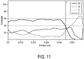
- the figure 11 is a chemical element detection graph by transmission electron microscopy (STEM / EELS) techniques, as a function (on the x-axis) of the position along a segment starting from a core of a particle and going on the layer 16 of this same particle then towards the outside of this particle.
- the y-axis is an intensity related to the proportion of detected elements.
- Example 1 the layer 16 does not include the first chemical element (in any form).
- Example 1 and Example 2 the core 15 does not include the first chemical element in oxidized form, but includes this first chemical element in unoxidized form only.
- certain cores 15 also comprise the second chemical element (traces of aluminum), and the existence of grains composed of aluminum is noted.
Landscapes
- Chemical & Material Sciences (AREA)
- Organic Chemistry (AREA)
- Chemical Kinetics & Catalysis (AREA)
- Inorganic Chemistry (AREA)
- General Health & Medical Sciences (AREA)
- Health & Medical Sciences (AREA)
- Toxicology (AREA)
- Physics & Mathematics (AREA)
- Dispersion Chemistry (AREA)
- Optics & Photonics (AREA)
- Electromagnetism (AREA)
- Physical Or Chemical Processes And Apparatus (AREA)
- Silicon Compounds (AREA)
- Compounds Of Alkaline-Earth Elements, Aluminum Or Rare-Earth Metals (AREA)
Claims (25)
- Verfahren zum Herstellen von Teilchen (10), umfassend die nachfolgenden Schritte:- Einleiten zumindest eines Reaktionsstroms (1, 100, 101, 102, 103, 104, 105, 106), der als erstes chemisches Element Silicium enthält und sich in einer Strömungsrichtung (11) ausbreitet, in eine Reaktionskammer (8),- Projizieren eines Strahlungsbündels (3) durch die Reaktionskammer (8), das sich mit jedem Reaktionsstrom (1, 100, 101, 102, 103, 104, 105, 106) in einem Wechselwirkungsbereich (14) pro Reaktionsstrom schneidet, um in jedem Reaktionsstrom Teilchenkerne (15) zu bilden, die das erste chemische Element enthalten, und- Einleiten eines zweiten chemischen Elements in die Reaktionskammer (8), das mit jedem Reaktionsstrom (1, 100, 101, 102, 103, 104, 105, 106) in Wechselwirkung tritt, um die Teilchenkerne (15) mit einer Schicht (16) zu überdecken, die das zweite chemische Element enthält, wobei dieses zweite chemische Element Aluminium ist,wobei das zweite chemische Element in die Kammer (8) in einen Gasstrom (2; 7) eingeleitet wird, der jeden Reaktionsstrom (1, 100, 101, 102, 103, 104, 105, 106) umgibt,
dadurch gekennzeichnet, dass:- das zweite chemische Element in die Kammer (8) in einen Umfangsgasstrom (7) eingeleitet wird, der jeden Reaktionsstrom (1, 100, 101, 102, 103, 104, 105, 106) umgibt, ausgehend von mehreren Stellen (17) ausgegeben wird, die entlang einer jeden Reaktionsstrom (1, 100, 101, 102, 103, 104, 105, 106) umgebenden, geschlossenen Kurve verteilt sind, und sich in Richtung eines jeden Reaktionsstroms ausbreitet, wobei das zweite chemische Element in die Kammer (8) in den Umfangsgasstrom (7) nach dem Wechselwirkungsbereich (14) eines jeden Reaktionsstroms eingeleitet wird, und/oder- es ferner als Schritt das Einleiten eines Umhüllungsgasstroms (2), der jeden Reaktionsstrom (1, 100, 101, 102, 103, 104, 105, 106) umgibt und sich in Strömungsrichtung (11) ausbreitet, in die Reaktionskammer (8) vor dem Wechselwirkungsbereich (14) eines jeden Reaktionsstroms umfasst, wobei das zweite chemische Element vor dem Wechselwirkungsbereich (14) eines jeden Reaktionsstroms in die Kammer (8) in den Umhüllungsgasstrom (2) eingeleitet wird. - Verfahren nach Anspruch 1, dadurch gekennzeichnet, dass jeder Reaktionsstrom (1, 100, 101, 102, 103, 104, 105, 106) frei von das erste chemische Element oxidierenden Oxidationsmitteln ist und die Teilchenkerne (15) das erste chemische Element in nicht oxidierter Form enthalten.
- Verfahren nach Anspruch 1 oder 2, dadurch gekennzeichnet, dass das zweite chemische Element in die Kammer (8) in den Umfangsgasstrom (7) eingeleitet wird, der jeden Reaktionsstrom (1, 100, 101, 102, 103, 104, 105, 106) umgibt, ausgehend von mehreren Stellen (17) ausgegeben wird, die entlang der jeden Reaktionsstrom (1, 100, 101, 102, 103, 104, 105, 106) umgebenden geschlossenen Kurve verteilt sind, und sich in Richtung eines jeden Reaktionsstroms ausbreitet, wobei das zweite chemische Element nach dem Wechselwirkungsbereich (14) eines jeden Reaktionsstroms in die Kammer (8) in den Umfangsgasstrom (7) eingeleitet wird.
- Verfahren nach einem der Ansprüche 1 bis 3, dadurch gekennzeichnet, dass es den Schritt des Einleitens des Umhüllungsgasstroms (2), der jeden Reaktionsstrom (1, 100, 101, 102, 103, 104, 105, 106) umgibt und sich in Strömungsrichtung (11) ausbreitet, vor dem Wechselwirkungsbereich (14) eines jeden Reaktionsstroms in die Reaktionskammer (8) umfasst, wobei das zweite chemische Element vor dem Wechselwirkungsbereich (14) eines jeden Reaktionsstroms in die Kammer (8) in den Umhüllungsgasstrom (2) eingeleitet wird.
- Verfahren nach Anspruch 4, dadurch gekennzeichnet, dass das Einleiten des zumindest einen Reaktionsstroms ein Einführen von zumindest einer Ausrichtung von mehreren Reaktionsströmen (101, 102, 103; 104, 105, 106) umfasst, die durch den Umhüllungsgasstrom (2) voneinander getrennt sind und jeweils das erste chemische Element enthalten und sich jeweils in Strömungsrichtung (11) ausbreiten.
- Verfahren nach Anspruch 5, dadurch gekennzeichnet, dass das Strahlungsbündel (3) sich entlang einer Strahlungsrichtung (12) ausbreitet, die senkrecht zur Strömungsrichtung (11) verläuft, und dass die Ströme einer jeden Ausrichtung von Reaktionsströmen (101, 102, 103; 104, 105, 106) entlang einer Ausrichtungsrichtung (18) ausgerichtet werden, die senkrecht zur Strömungsrichtung (11) und zur Strahlungsrichtung (12) verläuft.
- Verfahren nach einem der Ansprüche 1 bis 6, dadurch gekennzeichnet, dass das Strahlungsbündel (3) sich entlang einer Strahlungsrichtung (12) ausbreitet, die senkrecht zur Strömungsrichtung (11) verläuft, und dass jeder Reaktionsstrom (1, 100, 101, 102, 103, 104, 105, 106) in einer Ebene senkrecht zur Strömungsrichtung (11) einen Abschnitt aufweist, der sich längs entlang einer Ausdehnungsrichtung (13) erstreckt, die senkrecht zur Strömungsrichtung (11) und zur Strahlungsrichtung (12) verläuft.
- Verfahren nach einem der vorangehenden Ansprüche, dadurch gekennzeichnet, dass das zweite chemische Element in die Kammer (8) mit dem ersten chemischen Element in jeden Reaktionsstrom (1, 100, 101, 102, 103, 104, 105, 106) vor dem Wechselwirkungsbereich (14) eines jeden Reaktionsstroms eingeleitet wird.
- Verfahren nach einem der vorangehenden Ansprüche, dadurch gekennzeichnet, dass das erste chemische Element in Form von SiH4 in die Kammer (8) eingeleitet wird.
- Verfahren nach einem der vorangehenden Ansprüche, dadurch gekennzeichnet, dass die Kerne (15) der Teilchen (10) aus Silicium bestehen.
- Verfahren nach einem der Ansprüche 1 bis 9, dadurch gekennzeichnet, dass Kohlenstoff mit dem ersten chemischen Element in jeden Reaktionsstrom vor dem Wechselwirkungsbereich eines jeden Reaktionsstroms in die Kammer eingeleitet wird, so dass die Teilchenkerne Siliciumcarbid enthalten.
- Teilchen, jeweils enthaltend:- einen Kern (15), der als erstes chemisches Element Silicium nur in nicht oxidierter Form enthält und einen Durchmesser zwischen 3 und 900 nm hat, und- einer den Kern umgebenden Schicht (16), die als zweites chemisches Element Aluminium enthält und eine Schichtdicke von mindestens 0,5 nm hat.
- Teilchen nach Anspruch 12, dadurch gekennzeichnet, dass deren Durchmesser kleiner als 100 Nanometer ist.
- Teilchen nach Anspruch 12 oder 13, dadurch gekennzeichnet, dass der Kern aus Silicium besteht.
- Teilchen nach einem der Ansprüche 12 bis 14, dadurch gekennzeichnet, dass der Kern Siliciumcarbid enthält oder daraus besteht.
- Verfahren, dadurch gekennzeichnet, dass Aluminiumteilchen mit Teilchen nach einem der Ansprüche 12 bis 15 vermischt werden, dann das Gemisch erwärmt und dann wieder abgekühlt wird, so dass die Aluminiumteilchen fest mit den Teilchen nach einem der Ansprüche 12 bis 15 verbunden werden, um ein mit Silicium oder Siliciumcarbid angereichertes Aluminiummaterial zu erhalten.
- Vorrichtung (9) zum Herstellen von Teilchen (10), enthaltend:- eine Reagenzquelle mit einem Reagenz, wobei dieses Reagenz als erstes chemisches Element Silicium enthält;- eine Reaktionskammer (8), die mit der Reagenzquelle verbunden ist;- einen Reagenzinjektor, der dazu angeordnet ist, von der Reagenzquelle stammend zumindest einen Reaktionsstrom (1, 100, 101, 102, 103, 104, 105, 106) in die Kammer einzuleiten, der das Reagenz enthält und sich in einer Strömungsrichtung (11) in einem Reaktionsstrombereich (6) pro Reaktionsstrom ausbreitet,- einen Strahlungsbündelsender, der dazu angeordnet ist, das Strahlungsbündel (3) durch die Reaktionskammer (8) zu projizieren, das sich mit jedem Bereich (6) des Reaktionsstroms (1, 100, 101, 102, 103, 104, 105, 106) in einem Wechselwirkungsbereich (14) pro Reaktionsstrom schneidet,- eine Quelle eines zweiten chemischen Elements, wobei dieses zweite chemische Element Aluminium ist, und- einen Injektor für das zweite Element, der dazu ausgebildet ist, das zweite chemische Element ausgehend von der Quelle des zweiten Elements in die Reaktionskammer (8) einzuleiten, so dass dieses zweite chemische Element dazu geeignet ist, in der Kammer (8) mit jedem Reaktionsstrom (1, 100, 101, 102, 103, 104, 105, 106) in Wechselwirkung zu treten,wobei der Injektor für das zweite chemische Element dazu ausgebildet ist, das zweite chemische Element in die Kammer (8) in einen Gasstrom (2; 7) einzuleiten, welcher jeden Reaktionsstrom (1, 100, 101, 102, 103, 104, 105, 106) umgibt,
dadurch gekennzeichnet, dass- der Injektor für das zweite chemische Element dazu ausgebildet ist, das zweite chemische Element in die Kammer (8) in einen Umfangsgasstrom (7), der jeden Reaktionsstrom (1, 100, 101, 102, 103, 104, 105, 106) umgibt, einzuleiten, wobei der Umfangsgasstrom (7) ausgehend von mehreren Stellen (17) ausgegeben wird, die entlang einer jeden Reaktionsstrom umgebenden, geschlossenen Kurve verteilt sind und dazu angeordnet sind, den Umfangsgasstrom in Richtung eines jeden Reaktionsstroms zu lenken, wobei der Injektor für das zweite chemische Element angeordnet ist zum Einleiten des zweiten chemischen Elements in die Kammer (8) in den Umfangsgasstrom (7) nach dem Wechselwirkungsbereich (14) eines jeden Reaktionsstroms einzuleiten, und/oder dass- sie ferner einen Injektor für Umhüllungsgas enthält, der dazu angeordnet ist, vor dem Wechselwirkungsbereich (14) eines jeden Reaktionsstroms einen Umhüllungsgasstrom (2) in die Kammer (8) einzuleiten, der jeden Reaktionsstrom (1, 100, 101, 102, 103, 104, 105, 106) umgibt und sich in Strömungsrichtung (11) ausbreitet, und dass der Injektor für das zweite chemische Element den Umhüllungsgasinjektor enthält. - Vorrichtung nach Anspruch 17, dadurch gekennzeichnet, dass das Reagenz (1; 101, 102, 103) frei von das erste chemische Element oxidierenden Oxidationsmitteln ist.
- Vorrichtung nach Anspruch 17 oder 18, dadurch gekennzeichnet, dass der Injektor für das zweite chemische Element dazu angeordnet ist, das zweite chemische Element in die Kammer (8) in den Umfangsgasstrom (7), der jeden Reaktionsstrom (1, 100, 101, 102, 103, 104, 105, 106) umgibt, einzuleiten, wobei der Umfangsgasstrom (7) ausgehend von mehreren Stellen (17) ausgegeben wird, die entlang der jeden Reaktionsstrom umgebenden geschlossenen Kurve verteilt sind und dazu angeordnet sind, den Umfangsgasstrom in Richtung eines jeden Reaktionsstroms zu lenken, wobei der Injektor für das zweite chemische Element dazu angeordnet ist, das zweite chemische Element nach dem Wechselwirkungsbereich (14) eines jeden Reaktionsstroms in die Kammer (8) in den Umfangsgasstrom (7) einzuleiten.
- Vorrichtung nach einem der Ansprüche 17 bis 19, dadurch gekennzeichnet, dass sie den Umhüllungsgasinjektor enthält, der dazu angeordnet ist, um vor dem Wechselwirkungsbereich (14) eines jeden Reaktionsstroms den Umhüllungsgasstrom (2) in die Reaktionskammer (8) einzuleiten, der jeden Reaktionsstrom (1, 100, 101, 102, 103, 104, 105, 106) umgibt und sich in Strömungsrichtung (11) ausbreitet, und dass der Injektor für das zweite chemische Element den Umhüllungsgasinjektor enthält.
- Vorrichtung nach Anspruch 20, dadurch gekennzeichnet, dass der Injektor für zumindest einen Reaktionsstrom dazu angeordnet ist, um zumindest eine Ausrichtung von mehreren Reaktionsströmen (1, 100, 101, 102, 103, 104, 105, 106) in die Kammer einzuführen, die durch den Umhüllungsgasstrom (2) voneinander getrennt sind und jeweils das erste chemische Element enthalten und sich jeweils in Strömungsrichtung (11) ausbreiten.
- Vorrichtung nach Anspruch 21, dadurch gekennzeichnet, dass der Emitter so angeordnet ist, dass das Strahlungsbündel (3) sich entlang einer Strahlungsrichtung (12) ausbreitet, die senkrecht zur Strömungsrichtung (11) verläuft, und dass der Injektor für zumindest einen Reaktionsstrom so angeordnet ist, dass die Ströme einer jeden Ausrichtung von Reaktionsströmen (101, 102, 103; 104, 105, 106) entlang einer Ausrichtungsrichtung (18) ausgerichtet sind, die senkrecht zur Strömungsrichtung (11) und zur Strahlungsrichtung (12) verläuft.
- Vorrichtung nach einem der Ansprüche 17 bis 22, dadurch gekennzeichnet, dass der Emitter so angeordnet ist, dass das Strahlungsbündel (3) sich entlang einer Strahlungsrichtung (12) ausbreitet, die senkrecht zur Strömungsrichtung (11) verläuft, und dass der Injektor für zumindest einen Reaktionsstrom so angeordnet ist, dass jeder Reaktionsstrom (1, 100, 101, 102, 103, 104, 105, 106) in einer Ebene senkrecht zur Strömungsrichtung (11) einen Abschnitt aufweist, der sich längs entlang einer Ausdehnungsrichtung (13) erstreckt, die senkrecht zur Strömungsrichtung (11) und zur Strahlungsrichtung (12) verläuft.
- Vorrichtung nach einem der Ansprüche 17 bis 23, dadurch gekennzeichnet, dass der Injektor für das zweite chemische Element dazu angeordnet ist, um das zweite Element mit dem ersten chemischen Element in jeden Reaktionsstrom (1, 100, 101, 102, 103, 104, 105, 106) vor dem Wechselwirkungsbereich (14) eines jeden Reaktionsstroms in die Kammer (8) einzuleiten.
- Vorrichtung nach einem der Ansprüche 17 bis 24, dadurch gekennzeichnet, dass das Reagenz ferner Kohlenstoff enthält.
Applications Claiming Priority (2)
| Application Number | Priority Date | Filing Date | Title |
|---|---|---|---|
| FR1361856A FR3013991B1 (fr) | 2013-11-29 | 2013-11-29 | Particules submicroniques comprenant de l'aluminium |
| PCT/EP2014/076021 WO2015079050A1 (fr) | 2013-11-29 | 2014-11-28 | Particules submicroniques comprenant de l'aluminium |
Publications (2)
| Publication Number | Publication Date |
|---|---|
| EP3074469A1 EP3074469A1 (de) | 2016-10-05 |
| EP3074469B1 true EP3074469B1 (de) | 2018-10-17 |
Family
ID=50976683
Family Applications (1)
| Application Number | Title | Priority Date | Filing Date |
|---|---|---|---|
| EP14816143.3A Active EP3074469B1 (de) | 2013-11-29 | 2014-11-28 | Submikrometergrosse aluminiumhaltige teilchen |
Country Status (4)
| Country | Link |
|---|---|
| US (1) | US10227236B2 (de) |
| EP (1) | EP3074469B1 (de) |
| FR (1) | FR3013991B1 (de) |
| WO (1) | WO2015079050A1 (de) |
Families Citing this family (1)
| Publication number | Priority date | Publication date | Assignee | Title |
|---|---|---|---|---|
| CN103833035B (zh) * | 2014-03-06 | 2017-01-11 | 台州市一能科技有限公司 | 一种碳化硅的制备方法 |
Family Cites Families (11)
| Publication number | Priority date | Publication date | Assignee | Title |
|---|---|---|---|---|
| US4424066A (en) * | 1982-05-20 | 1984-01-03 | Gte Laboratories Incorporated | Alumina coated composite silicon aluminum oxynitride cutting tools |
| US4505720A (en) * | 1983-06-29 | 1985-03-19 | Minnesota Mining And Manufacturing Company | Granular silicon carbide abrasive grain coated with refractory material, method of making the same and articles made therewith |
| US5874134A (en) * | 1996-01-29 | 1999-02-23 | Regents Of The University Of Minnesota | Production of nanostructured materials by hypersonic plasma particle deposition |
| WO2001032799A1 (en) * | 1999-11-04 | 2001-05-10 | Nanogram Corporation | Particle dispersions |
| US7521097B2 (en) * | 2003-06-06 | 2009-04-21 | Nanogram Corporation | Reactive deposition for electrochemical cell production |
| FR2877591B1 (fr) | 2004-11-09 | 2007-06-08 | Commissariat Energie Atomique | Systeme et procede de production de poudres nanometriques ou sub-micrometriques en flux continu sous l'action d'une pyrolyse laser |
| EP1760045A1 (de) * | 2005-09-03 | 2007-03-07 | Degussa GmbH | Nanoskalige Siliziumteilchen |
| FR2894493B1 (fr) | 2005-12-08 | 2008-01-18 | Commissariat Energie Atomique | Systeme et procede de production de poudres nanometriques ou sub-micrometriques en flux continu sous l'action d'une pyrolyse laser |
| DE102006038518A1 (de) * | 2006-08-17 | 2008-02-21 | Evonik Degussa Gmbh | Umhüllte Zinkoxidpartikel |
| US20090026421A1 (en) * | 2007-01-22 | 2009-01-29 | Xuegeng Li | Optimized laser pyrolysis reactor and methods therefor |
| FR2998485B1 (fr) * | 2012-11-26 | 2015-01-02 | Commissariat Energie Atomique | Dispositif pour la synthese de nanoparticules de type cœur-coquille par pyrolyse laser et procede associe. |
-
2013
- 2013-11-29 FR FR1361856A patent/FR3013991B1/fr not_active Expired - Fee Related
-
2014
- 2014-11-28 EP EP14816143.3A patent/EP3074469B1/de active Active
- 2014-11-28 WO PCT/EP2014/076021 patent/WO2015079050A1/fr not_active Ceased
- 2014-11-28 US US15/039,824 patent/US10227236B2/en not_active Expired - Fee Related
Non-Patent Citations (1)
| Title |
|---|
| None * |
Also Published As
| Publication number | Publication date |
|---|---|
| US10227236B2 (en) | 2019-03-12 |
| FR3013991A1 (fr) | 2015-06-05 |
| EP3074469A1 (de) | 2016-10-05 |
| FR3013991B1 (fr) | 2019-04-26 |
| US20160376158A1 (en) | 2016-12-29 |
| WO2015079050A1 (fr) | 2015-06-04 |
Similar Documents
| Publication | Publication Date | Title |
|---|---|---|
| EP2121175B1 (de) | Nanopartikelsynthese mittels laserhydrolyse | |
| Lu et al. | Polymer-directed growth of plasmonic aluminum nanocrystals | |
| van der Hoeven et al. | Silica‐coated gold nanorod supraparticles: a tunable platform for surface enhanced Raman spectroscopy | |
| EP2038238B1 (de) | Max-phase-pulver und herstellungsverfahren dafür | |
| EP2872444B1 (de) | Verfahren zur herstellung mehrschichtiger submikronpartikel durch laserpyrolyse | |
| Lau et al. | Enhanced ordering in gold nanoparticles self-assembly through excess free ligands | |
| EP3409349A1 (de) | Partikel für die herstellung von metallteilen durch 3d-druck, und herstellungsverfahren dieser metallteile | |
| FR3013061A1 (fr) | Procede de fabrication au defile et en continu de nanostructures alignees sur un support et dispositif associe | |
| FR3051699A1 (fr) | Dispositif d'atomisation et de depot chimique en phase vapeur | |
| US20030157867A1 (en) | Particle forming method | |
| EP2922626B1 (de) | Vorrichtung zur synthese von kern-hülle-nanopartikeln durch laserpyrolyse und zugehöriges verfahren | |
| FR2642673A1 (fr) | Tuyere de pulverisation a laser a ecoulement transversal et procede correspondant | |
| FR3008644A1 (fr) | Procede de fabrication par frittage d'une piece multicouche | |
| Peter et al. | High rate deposition system for metal-cluster/SiO x C y H z–polymer nanocomposite thin films | |
| Cui et al. | Mechanistic study on reduction reaction of nitro compounds catalyzed by gold nanoparticles using in situ SERS monitoring | |
| EP3074469B1 (de) | Submikrometergrosse aluminiumhaltige teilchen | |
| In et al. | Effect of enhanced thermal stability of alumina support layer on growth of vertically aligned single-walled carbon nanotubes and their application in nanofiltration membranes | |
| EP3645460B1 (de) | Verfahren zur herstellung von an einem substrat befestigten kohlenstoffnanoröhrchen | |
| EP2978871B1 (de) | Verfahren für eine diamantdampfabscheidung | |
| US7759229B2 (en) | Charge-free method of forming nanostructures on a substrate | |
| EP2695967B1 (de) | Syntheseverfahren eines Nanostruktur-Verbundmaterials, und entsprechende Vorrichtung für dessen Umsetzung | |
| Fujimaki et al. | Surface-enhanced Raman scattering from Ag nanoparticles formed by visible laser irradiation of thermally annealed AgOx thin films | |
| EP3548169A1 (de) | Vorrichtung zur synthese von kern-schale-nanopartikeln durch laserpyrolyse und zugehöriges verfahren | |
| EP1214462B1 (de) | Verfahren zur herstellung eines diamant-beschichteten metallischen gegenstandes und solcher gegenstand so hergestellt | |
| FR2748759A1 (fr) | Lame composite, notamment racle pour l'industrie papetiere |
Legal Events
| Date | Code | Title | Description |
|---|---|---|---|
| PUAI | Public reference made under article 153(3) epc to a published international application that has entered the european phase |
Free format text: ORIGINAL CODE: 0009012 |
|
| 17P | Request for examination filed |
Effective date: 20160622 |
|
| AK | Designated contracting states |
Kind code of ref document: A1 Designated state(s): AL AT BE BG CH CY CZ DE DK EE ES FI FR GB GR HR HU IE IS IT LI LT LU LV MC MK MT NL NO PL PT RO RS SE SI SK SM TR |
|
| AX | Request for extension of the european patent |
Extension state: BA ME |
|
| RIN1 | Information on inventor provided before grant (corrected) |
Inventor name: TENEGAL, FRANCOIS Inventor name: REAU, ADRIEN |
|
| DAX | Request for extension of the european patent (deleted) | ||
| STAA | Information on the status of an ep patent application or granted ep patent |
Free format text: STATUS: EXAMINATION IS IN PROGRESS |
|
| 17Q | First examination report despatched |
Effective date: 20171016 |
|
| GRAP | Despatch of communication of intention to grant a patent |
Free format text: ORIGINAL CODE: EPIDOSNIGR1 |
|
| GRAJ | Information related to disapproval of communication of intention to grant by the applicant or resumption of examination proceedings by the epo deleted |
Free format text: ORIGINAL CODE: EPIDOSDIGR1 |
|
| RIC1 | Information provided on ipc code assigned before grant |
Ipc: C01B 33/027 20060101ALI20180308BHEP Ipc: C01B 32/956 20170101ALI20180308BHEP Ipc: B01J 19/24 20060101ALI20180308BHEP Ipc: C01B 33/029 20060101ALI20180308BHEP Ipc: B01J 4/00 20060101ALI20180308BHEP Ipc: B01J 13/04 20060101ALI20180308BHEP Ipc: B01J 19/12 20060101ALI20180308BHEP Ipc: B01J 12/00 20060101ALI20180308BHEP Ipc: C09C 1/30 20060101AFI20180308BHEP |
|
| GRAP | Despatch of communication of intention to grant a patent |
Free format text: ORIGINAL CODE: EPIDOSNIGR1 |
|
| STAA | Information on the status of an ep patent application or granted ep patent |
Free format text: STATUS: GRANT OF PATENT IS INTENDED |
|
| INTG | Intention to grant announced |
Effective date: 20180509 |
|
| GRAS | Grant fee paid |
Free format text: ORIGINAL CODE: EPIDOSNIGR3 |
|
| GRAA | (expected) grant |
Free format text: ORIGINAL CODE: 0009210 |
|
| STAA | Information on the status of an ep patent application or granted ep patent |
Free format text: STATUS: THE PATENT HAS BEEN GRANTED |
|
| AK | Designated contracting states |
Kind code of ref document: B1 Designated state(s): AL AT BE BG CH CY CZ DE DK EE ES FI FR GB GR HR HU IE IS IT LI LT LU LV MC MK MT NL NO PL PT RO RS SE SI SK SM TR |
|
| REG | Reference to a national code |
Ref country code: GB Ref legal event code: FG4D Free format text: NOT ENGLISH |
|
| REG | Reference to a national code |
Ref country code: FR Ref legal event code: PLFP Year of fee payment: 5 |
|
| REG | Reference to a national code |
Ref country code: CH Ref legal event code: EP |
|
| REG | Reference to a national code |
Ref country code: IE Ref legal event code: FG4D Free format text: LANGUAGE OF EP DOCUMENT: FRENCH |
|
| REG | Reference to a national code |
Ref country code: DE Ref legal event code: R096 Ref document number: 602014034370 Country of ref document: DE Ref country code: AT Ref legal event code: REF Ref document number: 1053984 Country of ref document: AT Kind code of ref document: T Effective date: 20181115 |
|
| REG | Reference to a national code |
Ref country code: CH Ref legal event code: NV Representative=s name: DENNEMEYER AG, CH |
|
| REG | Reference to a national code |
Ref country code: NL Ref legal event code: MP Effective date: 20181017 |
|
| REG | Reference to a national code |
Ref country code: LT Ref legal event code: MG4D |
|
| REG | Reference to a national code |
Ref country code: AT Ref legal event code: MK05 Ref document number: 1053984 Country of ref document: AT Kind code of ref document: T Effective date: 20181017 |
|
| PG25 | Lapsed in a contracting state [announced via postgrant information from national office to epo] |
Ref country code: NL Free format text: LAPSE BECAUSE OF FAILURE TO SUBMIT A TRANSLATION OF THE DESCRIPTION OR TO PAY THE FEE WITHIN THE PRESCRIBED TIME-LIMIT Effective date: 20181017 |
|
| PG25 | Lapsed in a contracting state [announced via postgrant information from national office to epo] |
Ref country code: FI Free format text: LAPSE BECAUSE OF FAILURE TO SUBMIT A TRANSLATION OF THE DESCRIPTION OR TO PAY THE FEE WITHIN THE PRESCRIBED TIME-LIMIT Effective date: 20181017 Ref country code: NO Free format text: LAPSE BECAUSE OF FAILURE TO SUBMIT A TRANSLATION OF THE DESCRIPTION OR TO PAY THE FEE WITHIN THE PRESCRIBED TIME-LIMIT Effective date: 20190117 Ref country code: IS Free format text: LAPSE BECAUSE OF FAILURE TO SUBMIT A TRANSLATION OF THE DESCRIPTION OR TO PAY THE FEE WITHIN THE PRESCRIBED TIME-LIMIT Effective date: 20190217 Ref country code: HR Free format text: LAPSE BECAUSE OF FAILURE TO SUBMIT A TRANSLATION OF THE DESCRIPTION OR TO PAY THE FEE WITHIN THE PRESCRIBED TIME-LIMIT Effective date: 20181017 Ref country code: LT Free format text: LAPSE BECAUSE OF FAILURE TO SUBMIT A TRANSLATION OF THE DESCRIPTION OR TO PAY THE FEE WITHIN THE PRESCRIBED TIME-LIMIT Effective date: 20181017 Ref country code: BG Free format text: LAPSE BECAUSE OF FAILURE TO SUBMIT A TRANSLATION OF THE DESCRIPTION OR TO PAY THE FEE WITHIN THE PRESCRIBED TIME-LIMIT Effective date: 20190117 Ref country code: PL Free format text: LAPSE BECAUSE OF FAILURE TO SUBMIT A TRANSLATION OF THE DESCRIPTION OR TO PAY THE FEE WITHIN THE PRESCRIBED TIME-LIMIT Effective date: 20181017 Ref country code: ES Free format text: LAPSE BECAUSE OF FAILURE TO SUBMIT A TRANSLATION OF THE DESCRIPTION OR TO PAY THE FEE WITHIN THE PRESCRIBED TIME-LIMIT Effective date: 20181017 Ref country code: LV Free format text: LAPSE BECAUSE OF FAILURE TO SUBMIT A TRANSLATION OF THE DESCRIPTION OR TO PAY THE FEE WITHIN THE PRESCRIBED TIME-LIMIT Effective date: 20181017 Ref country code: AT Free format text: LAPSE BECAUSE OF FAILURE TO SUBMIT A TRANSLATION OF THE DESCRIPTION OR TO PAY THE FEE WITHIN THE PRESCRIBED TIME-LIMIT Effective date: 20181017 |
|
| PG25 | Lapsed in a contracting state [announced via postgrant information from national office to epo] |
Ref country code: PT Free format text: LAPSE BECAUSE OF FAILURE TO SUBMIT A TRANSLATION OF THE DESCRIPTION OR TO PAY THE FEE WITHIN THE PRESCRIBED TIME-LIMIT Effective date: 20190217 Ref country code: AL Free format text: LAPSE BECAUSE OF FAILURE TO SUBMIT A TRANSLATION OF THE DESCRIPTION OR TO PAY THE FEE WITHIN THE PRESCRIBED TIME-LIMIT Effective date: 20181017 Ref country code: RS Free format text: LAPSE BECAUSE OF FAILURE TO SUBMIT A TRANSLATION OF THE DESCRIPTION OR TO PAY THE FEE WITHIN THE PRESCRIBED TIME-LIMIT Effective date: 20181017 Ref country code: GR Free format text: LAPSE BECAUSE OF FAILURE TO SUBMIT A TRANSLATION OF THE DESCRIPTION OR TO PAY THE FEE WITHIN THE PRESCRIBED TIME-LIMIT Effective date: 20190118 Ref country code: SE Free format text: LAPSE BECAUSE OF FAILURE TO SUBMIT A TRANSLATION OF THE DESCRIPTION OR TO PAY THE FEE WITHIN THE PRESCRIBED TIME-LIMIT Effective date: 20181017 |
|
| REG | Reference to a national code |
Ref country code: DE Ref legal event code: R097 Ref document number: 602014034370 Country of ref document: DE |
|
| PG25 | Lapsed in a contracting state [announced via postgrant information from national office to epo] |
Ref country code: DK Free format text: LAPSE BECAUSE OF FAILURE TO SUBMIT A TRANSLATION OF THE DESCRIPTION OR TO PAY THE FEE WITHIN THE PRESCRIBED TIME-LIMIT Effective date: 20181017 Ref country code: IT Free format text: LAPSE BECAUSE OF FAILURE TO SUBMIT A TRANSLATION OF THE DESCRIPTION OR TO PAY THE FEE WITHIN THE PRESCRIBED TIME-LIMIT Effective date: 20181017 Ref country code: LU Free format text: LAPSE BECAUSE OF NON-PAYMENT OF DUE FEES Effective date: 20181128 Ref country code: CZ Free format text: LAPSE BECAUSE OF FAILURE TO SUBMIT A TRANSLATION OF THE DESCRIPTION OR TO PAY THE FEE WITHIN THE PRESCRIBED TIME-LIMIT Effective date: 20181017 |
|
| REG | Reference to a national code |
Ref country code: BE Ref legal event code: MM Effective date: 20181130 |
|
| REG | Reference to a national code |
Ref country code: IE Ref legal event code: MM4A |
|
| PLBE | No opposition filed within time limit |
Free format text: ORIGINAL CODE: 0009261 |
|
| STAA | Information on the status of an ep patent application or granted ep patent |
Free format text: STATUS: NO OPPOSITION FILED WITHIN TIME LIMIT |
|
| PG25 | Lapsed in a contracting state [announced via postgrant information from national office to epo] |
Ref country code: MC Free format text: LAPSE BECAUSE OF FAILURE TO SUBMIT A TRANSLATION OF THE DESCRIPTION OR TO PAY THE FEE WITHIN THE PRESCRIBED TIME-LIMIT Effective date: 20181017 Ref country code: SK Free format text: LAPSE BECAUSE OF FAILURE TO SUBMIT A TRANSLATION OF THE DESCRIPTION OR TO PAY THE FEE WITHIN THE PRESCRIBED TIME-LIMIT Effective date: 20181017 Ref country code: RO Free format text: LAPSE BECAUSE OF FAILURE TO SUBMIT A TRANSLATION OF THE DESCRIPTION OR TO PAY THE FEE WITHIN THE PRESCRIBED TIME-LIMIT Effective date: 20181017 Ref country code: EE Free format text: LAPSE BECAUSE OF FAILURE TO SUBMIT A TRANSLATION OF THE DESCRIPTION OR TO PAY THE FEE WITHIN THE PRESCRIBED TIME-LIMIT Effective date: 20181017 Ref country code: SM Free format text: LAPSE BECAUSE OF FAILURE TO SUBMIT A TRANSLATION OF THE DESCRIPTION OR TO PAY THE FEE WITHIN THE PRESCRIBED TIME-LIMIT Effective date: 20181017 |
|
| 26N | No opposition filed |
Effective date: 20190718 |
|
| PG25 | Lapsed in a contracting state [announced via postgrant information from national office to epo] |
Ref country code: SI Free format text: LAPSE BECAUSE OF FAILURE TO SUBMIT A TRANSLATION OF THE DESCRIPTION OR TO PAY THE FEE WITHIN THE PRESCRIBED TIME-LIMIT Effective date: 20181017 Ref country code: IE Free format text: LAPSE BECAUSE OF NON-PAYMENT OF DUE FEES Effective date: 20181128 |
|
| PG25 | Lapsed in a contracting state [announced via postgrant information from national office to epo] |
Ref country code: BE Free format text: LAPSE BECAUSE OF NON-PAYMENT OF DUE FEES Effective date: 20181130 |
|
| PG25 | Lapsed in a contracting state [announced via postgrant information from national office to epo] |
Ref country code: MT Free format text: LAPSE BECAUSE OF FAILURE TO SUBMIT A TRANSLATION OF THE DESCRIPTION OR TO PAY THE FEE WITHIN THE PRESCRIBED TIME-LIMIT Effective date: 20181017 |
|
| PGFP | Annual fee paid to national office [announced via postgrant information from national office to epo] |
Ref country code: DE Payment date: 20191121 Year of fee payment: 6 |
|
| PG25 | Lapsed in a contracting state [announced via postgrant information from national office to epo] |
Ref country code: TR Free format text: LAPSE BECAUSE OF FAILURE TO SUBMIT A TRANSLATION OF THE DESCRIPTION OR TO PAY THE FEE WITHIN THE PRESCRIBED TIME-LIMIT Effective date: 20181017 |
|
| PGFP | Annual fee paid to national office [announced via postgrant information from national office to epo] |
Ref country code: CH Payment date: 20191121 Year of fee payment: 6 |
|
| PGFP | Annual fee paid to national office [announced via postgrant information from national office to epo] |
Ref country code: GB Payment date: 20191120 Year of fee payment: 6 |
|
| PG25 | Lapsed in a contracting state [announced via postgrant information from national office to epo] |
Ref country code: HU Free format text: LAPSE BECAUSE OF FAILURE TO SUBMIT A TRANSLATION OF THE DESCRIPTION OR TO PAY THE FEE WITHIN THE PRESCRIBED TIME-LIMIT; INVALID AB INITIO Effective date: 20141128 Ref country code: CY Free format text: LAPSE BECAUSE OF FAILURE TO SUBMIT A TRANSLATION OF THE DESCRIPTION OR TO PAY THE FEE WITHIN THE PRESCRIBED TIME-LIMIT Effective date: 20181017 Ref country code: MK Free format text: LAPSE BECAUSE OF NON-PAYMENT OF DUE FEES Effective date: 20181017 |
|
| REG | Reference to a national code |
Ref country code: DE Ref legal event code: R119 Ref document number: 602014034370 Country of ref document: DE |
|
| REG | Reference to a national code |
Ref country code: CH Ref legal event code: PL |
|
| GBPC | Gb: european patent ceased through non-payment of renewal fee |
Effective date: 20201128 |
|
| PG25 | Lapsed in a contracting state [announced via postgrant information from national office to epo] |
Ref country code: LI Free format text: LAPSE BECAUSE OF NON-PAYMENT OF DUE FEES Effective date: 20201130 Ref country code: CH Free format text: LAPSE BECAUSE OF NON-PAYMENT OF DUE FEES Effective date: 20201130 |
|
| PG25 | Lapsed in a contracting state [announced via postgrant information from national office to epo] |
Ref country code: DE Free format text: LAPSE BECAUSE OF NON-PAYMENT OF DUE FEES Effective date: 20210601 Ref country code: GB Free format text: LAPSE BECAUSE OF NON-PAYMENT OF DUE FEES Effective date: 20201128 |
|
| P01 | Opt-out of the competence of the unified patent court (upc) registered |
Effective date: 20230517 |
|
| PGFP | Annual fee paid to national office [announced via postgrant information from national office to epo] |
Ref country code: FR Payment date: 20251127 Year of fee payment: 12 |