EP3074073B1 - Medicament device - Google Patents
Medicament device Download PDFInfo
- Publication number
- EP3074073B1 EP3074073B1 EP14865715.8A EP14865715A EP3074073B1 EP 3074073 B1 EP3074073 B1 EP 3074073B1 EP 14865715 A EP14865715 A EP 14865715A EP 3074073 B1 EP3074073 B1 EP 3074073B1
- Authority
- EP
- European Patent Office
- Prior art keywords
- penetrator
- container
- medical device
- needle
- barrier
- Prior art date
- Legal status (The legal status is an assumption and is not a legal conclusion. Google has not performed a legal analysis and makes no representation as to the accuracy of the status listed.)
- Active
Links
- 239000003814 drug Substances 0.000 title claims description 66
- 239000012528 membrane Substances 0.000 claims description 51
- 238000007789 sealing Methods 0.000 claims description 45
- 230000004888 barrier function Effects 0.000 claims description 34
- 238000006073 displacement reaction Methods 0.000 claims description 31
- 238000000034 method Methods 0.000 claims description 23
- 230000001681 protective effect Effects 0.000 claims description 23
- 230000004913 activation Effects 0.000 claims description 21
- 230000000149 penetrating effect Effects 0.000 claims description 16
- 230000007246 mechanism Effects 0.000 claims description 15
- 239000012530 fluid Substances 0.000 claims description 12
- 238000004891 communication Methods 0.000 claims description 5
- 238000003780 insertion Methods 0.000 claims description 5
- 230000037431 insertion Effects 0.000 claims description 5
- 238000001802 infusion Methods 0.000 description 18
- 230000036961 partial effect Effects 0.000 description 16
- 230000036512 infertility Effects 0.000 description 11
- 238000002347 injection Methods 0.000 description 7
- 239000007924 injection Substances 0.000 description 7
- 229940079593 drug Drugs 0.000 description 6
- 230000008569 process Effects 0.000 description 6
- 239000011800 void material Substances 0.000 description 6
- 239000000463 material Substances 0.000 description 4
- 230000001954 sterilising effect Effects 0.000 description 4
- 238000004659 sterilization and disinfection Methods 0.000 description 4
- 239000000126 substance Substances 0.000 description 4
- IAYPIBMASNFSPL-UHFFFAOYSA-N Ethylene oxide Chemical compound C1CO1 IAYPIBMASNFSPL-UHFFFAOYSA-N 0.000 description 3
- 238000005452 bending Methods 0.000 description 3
- 229920001971 elastomer Polymers 0.000 description 3
- 239000004033 plastic Substances 0.000 description 3
- 125000006850 spacer group Chemical group 0.000 description 3
- 241001465754 Metazoa Species 0.000 description 2
- 238000000418 atomic force spectrum Methods 0.000 description 2
- 238000010276 construction Methods 0.000 description 2
- 230000008878 coupling Effects 0.000 description 2
- 238000010168 coupling process Methods 0.000 description 2
- 238000005859 coupling reaction Methods 0.000 description 2
- 230000000670 limiting effect Effects 0.000 description 2
- 238000004519 manufacturing process Methods 0.000 description 2
- 230000035515 penetration Effects 0.000 description 2
- 239000004743 Polypropylene Substances 0.000 description 1
- 230000002421 anti-septic effect Effects 0.000 description 1
- 150000001875 compounds Chemical class 0.000 description 1
- 230000006835 compression Effects 0.000 description 1
- 238000007906 compression Methods 0.000 description 1
- 230000003247 decreasing effect Effects 0.000 description 1
- 230000000881 depressing effect Effects 0.000 description 1
- 230000000994 depressogenic effect Effects 0.000 description 1
- 238000013461 design Methods 0.000 description 1
- 238000012377 drug delivery Methods 0.000 description 1
- 230000000694 effects Effects 0.000 description 1
- 239000000806 elastomer Substances 0.000 description 1
- 239000011888 foil Substances 0.000 description 1
- 230000036541 health Effects 0.000 description 1
- 238000009434 installation Methods 0.000 description 1
- 230000003993 interaction Effects 0.000 description 1
- 239000007788 liquid Substances 0.000 description 1
- 230000007774 longterm Effects 0.000 description 1
- 238000002483 medication Methods 0.000 description 1
- 239000002184 metal Substances 0.000 description 1
- 238000000465 moulding Methods 0.000 description 1
- 239000002985 plastic film Substances 0.000 description 1
- 229920006255 plastic film Polymers 0.000 description 1
- -1 polypropylene Polymers 0.000 description 1
- 229920001155 polypropylene Polymers 0.000 description 1
- 229920001296 polysiloxane Polymers 0.000 description 1
- 230000002028 premature Effects 0.000 description 1
- 230000000541 pulsatile effect Effects 0.000 description 1
- 230000002829 reductive effect Effects 0.000 description 1
- 239000007787 solid Substances 0.000 description 1
- 229910000811 surgical stainless steel Inorganic materials 0.000 description 1
- 239000010966 surgical stainless steel Substances 0.000 description 1
- 238000004383 yellowing Methods 0.000 description 1
Images


Classifications
-
- A—HUMAN NECESSITIES
- A61—MEDICAL OR VETERINARY SCIENCE; HYGIENE
- A61M—DEVICES FOR INTRODUCING MEDIA INTO, OR ONTO, THE BODY; DEVICES FOR TRANSDUCING BODY MEDIA OR FOR TAKING MEDIA FROM THE BODY; DEVICES FOR PRODUCING OR ENDING SLEEP OR STUPOR
- A61M5/00—Devices for bringing media into the body in a subcutaneous, intra-vascular or intramuscular way; Accessories therefor, e.g. filling or cleaning devices, arm-rests
- A61M5/178—Syringes
- A61M5/20—Automatic syringes, e.g. with automatically actuated piston rod, with automatic needle injection, filling automatically
-
- A—HUMAN NECESSITIES
- A61—MEDICAL OR VETERINARY SCIENCE; HYGIENE
- A61M—DEVICES FOR INTRODUCING MEDIA INTO, OR ONTO, THE BODY; DEVICES FOR TRANSDUCING BODY MEDIA OR FOR TAKING MEDIA FROM THE BODY; DEVICES FOR PRODUCING OR ENDING SLEEP OR STUPOR
- A61M5/00—Devices for bringing media into the body in a subcutaneous, intra-vascular or intramuscular way; Accessories therefor, e.g. filling or cleaning devices, arm-rests
- A61M5/14—Infusion devices, e.g. infusing by gravity; Blood infusion; Accessories therefor
- A61M5/142—Pressure infusion, e.g. using pumps
- A61M5/145—Pressure infusion, e.g. using pumps using pressurised reservoirs, e.g. pressurised by means of pistons
- A61M5/1452—Pressure infusion, e.g. using pumps using pressurised reservoirs, e.g. pressurised by means of pistons pressurised by means of pistons
- A61M5/1454—Pressure infusion, e.g. using pumps using pressurised reservoirs, e.g. pressurised by means of pistons pressurised by means of pistons spring-actuated, e.g. by a clockwork
-
- A—HUMAN NECESSITIES
- A61—MEDICAL OR VETERINARY SCIENCE; HYGIENE
- A61M—DEVICES FOR INTRODUCING MEDIA INTO, OR ONTO, THE BODY; DEVICES FOR TRANSDUCING BODY MEDIA OR FOR TAKING MEDIA FROM THE BODY; DEVICES FOR PRODUCING OR ENDING SLEEP OR STUPOR
- A61M5/00—Devices for bringing media into the body in a subcutaneous, intra-vascular or intramuscular way; Accessories therefor, e.g. filling or cleaning devices, arm-rests
- A61M5/14—Infusion devices, e.g. infusing by gravity; Blood infusion; Accessories therefor
- A61M5/162—Needle sets, i.e. connections by puncture between reservoir and tube ; Connections between reservoir and tube
-
- A—HUMAN NECESSITIES
- A61—MEDICAL OR VETERINARY SCIENCE; HYGIENE
- A61M—DEVICES FOR INTRODUCING MEDIA INTO, OR ONTO, THE BODY; DEVICES FOR TRANSDUCING BODY MEDIA OR FOR TAKING MEDIA FROM THE BODY; DEVICES FOR PRODUCING OR ENDING SLEEP OR STUPOR
- A61M5/00—Devices for bringing media into the body in a subcutaneous, intra-vascular or intramuscular way; Accessories therefor, e.g. filling or cleaning devices, arm-rests
- A61M5/178—Syringes
- A61M5/24—Ampoule syringes, i.e. syringes with needle for use in combination with replaceable ampoules or carpules, e.g. automatic
- A61M5/2455—Ampoule syringes, i.e. syringes with needle for use in combination with replaceable ampoules or carpules, e.g. automatic with sealing means to be broken or opened
- A61M5/2459—Ampoule syringes, i.e. syringes with needle for use in combination with replaceable ampoules or carpules, e.g. automatic with sealing means to be broken or opened upon internal pressure increase, e.g. pierced or burst
-
- A—HUMAN NECESSITIES
- A61—MEDICAL OR VETERINARY SCIENCE; HYGIENE
- A61M—DEVICES FOR INTRODUCING MEDIA INTO, OR ONTO, THE BODY; DEVICES FOR TRANSDUCING BODY MEDIA OR FOR TAKING MEDIA FROM THE BODY; DEVICES FOR PRODUCING OR ENDING SLEEP OR STUPOR
- A61M5/00—Devices for bringing media into the body in a subcutaneous, intra-vascular or intramuscular way; Accessories therefor, e.g. filling or cleaning devices, arm-rests
- A61M5/178—Syringes
- A61M5/24—Ampoule syringes, i.e. syringes with needle for use in combination with replaceable ampoules or carpules, e.g. automatic
- A61M5/2455—Ampoule syringes, i.e. syringes with needle for use in combination with replaceable ampoules or carpules, e.g. automatic with sealing means to be broken or opened
- A61M5/2466—Ampoule syringes, i.e. syringes with needle for use in combination with replaceable ampoules or carpules, e.g. automatic with sealing means to be broken or opened by piercing without internal pressure increase
-
- A—HUMAN NECESSITIES
- A61—MEDICAL OR VETERINARY SCIENCE; HYGIENE
- A61M—DEVICES FOR INTRODUCING MEDIA INTO, OR ONTO, THE BODY; DEVICES FOR TRANSDUCING BODY MEDIA OR FOR TAKING MEDIA FROM THE BODY; DEVICES FOR PRODUCING OR ENDING SLEEP OR STUPOR
- A61M5/00—Devices for bringing media into the body in a subcutaneous, intra-vascular or intramuscular way; Accessories therefor, e.g. filling or cleaning devices, arm-rests
- A61M5/178—Syringes
- A61M5/31—Details
- A61M5/315—Pistons; Piston-rods; Guiding, blocking or restricting the movement of the rod or piston; Appliances on the rod for facilitating dosing ; Dosing mechanisms
- A61M5/31565—Administration mechanisms, i.e. constructional features, modes of administering a dose
- A61M5/31566—Means improving security or handling thereof
- A61M5/31568—Means keeping track of the total dose administered, e.g. since the cartridge was inserted
-
- A—HUMAN NECESSITIES
- A61—MEDICAL OR VETERINARY SCIENCE; HYGIENE
- A61M—DEVICES FOR INTRODUCING MEDIA INTO, OR ONTO, THE BODY; DEVICES FOR TRANSDUCING BODY MEDIA OR FOR TAKING MEDIA FROM THE BODY; DEVICES FOR PRODUCING OR ENDING SLEEP OR STUPOR
- A61M5/00—Devices for bringing media into the body in a subcutaneous, intra-vascular or intramuscular way; Accessories therefor, e.g. filling or cleaning devices, arm-rests
- A61M5/178—Syringes
- A61M5/20—Automatic syringes, e.g. with automatically actuated piston rod, with automatic needle injection, filling automatically
- A61M2005/206—With automatic needle insertion
-
- A—HUMAN NECESSITIES
- A61—MEDICAL OR VETERINARY SCIENCE; HYGIENE
- A61M—DEVICES FOR INTRODUCING MEDIA INTO, OR ONTO, THE BODY; DEVICES FOR TRANSDUCING BODY MEDIA OR FOR TAKING MEDIA FROM THE BODY; DEVICES FOR PRODUCING OR ENDING SLEEP OR STUPOR
- A61M5/00—Devices for bringing media into the body in a subcutaneous, intra-vascular or intramuscular way; Accessories therefor, e.g. filling or cleaning devices, arm-rests
- A61M5/178—Syringes
- A61M5/24—Ampoule syringes, i.e. syringes with needle for use in combination with replaceable ampoules or carpules, e.g. automatic
- A61M2005/2403—Ampoule inserted into the ampoule holder
- A61M2005/2414—Ampoule inserted into the ampoule holder from the side
-
- A—HUMAN NECESSITIES
- A61—MEDICAL OR VETERINARY SCIENCE; HYGIENE
- A61M—DEVICES FOR INTRODUCING MEDIA INTO, OR ONTO, THE BODY; DEVICES FOR TRANSDUCING BODY MEDIA OR FOR TAKING MEDIA FROM THE BODY; DEVICES FOR PRODUCING OR ENDING SLEEP OR STUPOR
- A61M5/00—Devices for bringing media into the body in a subcutaneous, intra-vascular or intramuscular way; Accessories therefor, e.g. filling or cleaning devices, arm-rests
- A61M5/178—Syringes
- A61M5/24—Ampoule syringes, i.e. syringes with needle for use in combination with replaceable ampoules or carpules, e.g. automatic
- A61M5/2455—Ampoule syringes, i.e. syringes with needle for use in combination with replaceable ampoules or carpules, e.g. automatic with sealing means to be broken or opened
- A61M5/2466—Ampoule syringes, i.e. syringes with needle for use in combination with replaceable ampoules or carpules, e.g. automatic with sealing means to be broken or opened by piercing without internal pressure increase
- A61M2005/247—Ampoule syringes, i.e. syringes with needle for use in combination with replaceable ampoules or carpules, e.g. automatic with sealing means to be broken or opened by piercing without internal pressure increase with fixed or steady piercing means, e.g. piercing under movement of ampoule
Definitions
- the present invention relates to methods and devices for making a sterile connection, and more particularly, to methods and devices for making a sterile connection with a medicament source.
- Drug delivery devices in the form of infusers are known in the prior art for administering medicament to a patient.
- Infusers are intended for mounting onto a patient's skin for self-administration of a medicament.
- Activation of the infuser not only provides for injection of a needle into a patient's skin, but also to cause auto-drive of a plunger to drive medicament into the patient via the injected needle.
- Typical infuser constructions have the needle fixed to the reservoir.
- U.S. Patent No. 5,858,001 to Tsals et al. discloses an infuser that is activated through swivel displacement of a reservoir-containing body.
- a needle is fixed to the body to move therewith so that the swivel displacement of the body also causes the needle to penetrate the patient's skin.
- Other types of infusers are known, including those which use standard needle-mounted syringe barrels. With many infusers, the ability to control the insertion of the needle independent of the administration of medicament is limited.
- U.S. Patent No. 5,290,254 to Vaillancourt discloses a shielded cannula assembly that includes a tubular shield mounted over a cannula.
- the shield includes a resilient collapsible portion that collapses in an accordion-like manner when a longitudinal force is imposed on the shield.
- U.S. Patent No. 5,685,866 to Lopez discloses a needleless valve with a generally tubular body defining an internal cavity.
- the valve includes a hollow spike with a closed tip and a hole located in the tip. The spike is seated inside the cavity so that the tip is below the proximal end of the body.
- An annular support cuff is connected to the spike and seals off a portion of the cavity to define an upper portion of the cavity that includes the tip.
- the valve also includes a plastic, resilient silicone seal that fills the upper portion of cavity and the body opening, and covers the tip of the spike to present a flush surface.
- U.S. Patent Publication No. 2010/00022953 discloses a conduit assembly connected to a medication receiving conduit.
- the conduit assembly includes a cartridge receiving conduit surrounded by a sleeve, and a conduit sterility cap.
- a cartridge includes a spring-loaded casing, a cartridge sterility cap, and mechanical features for connecting with the conduit assembly. Upon such connection, an end of the cartridge breaches the conduit sterility cap. Subsequently, the spring drives the casing toward the cartridge receiving conduit, impales the cartridge sterility cap on the sleeve, and connects an interior of the casing with the cartridge receiving conduit.
- PCT Publication WO 2011/146166 discloses an infuser in which activation of an actuator causes a spring to move a stopper in a reservoir from a first position toward a second position, and also causes a needle driver to displace a patient needle from a first state toward a second state. The needle moves relative to the reservoir, and separately from the stopper.
- a sterile connection with a medicament storage device such as a medicament vial
- a medicament storage device such as a medicament vial
- Improvements in the equipment and/or the process of making a sterile connection with a medicament storage device are desirable.
- an apparatus for making a sterile connection including a container, a sealing member sealing a first end of the container, a barrier sealing a chamber in fluid communication with the sealing member, and a valve sleeve assembly.
- the valve assembly includes a flexible sleeve having a barrier portion at an end of the flexible sleeve, a hollow first penetrator adapted to displace relative to the flexible sleeve, and a hollow second penetrator at least partially disposed within the first penetrator and adapted to displace relative to the first penetrator and the flexible sleeve.
- An interior of the flexible sleeve is sterile.
- the flexible sleeve encloses the first penetrator and a penetrating end of the second penetrator.
- One of the container and the valve sleeve assembly is adapted to displace relative to the remaining one of the container and the valve sleeve assembly.
- the flexible sleeve is adapted to collapse, thereby displacing the outer penetrator relative to the flexible sleeve to pierce the barrier portion and the barrier.
- the second penetrator Upon further relative displacement between the container and the valve sleeve assembly, subsequent to the piercing of the barrier portion and the barrier, the second penetrator is adapted displace relative to the first penetrator, through the chamber, to pierce the sealing member to create a sterile connection with the interior of the container.
- the foregoing and other aspects of the present invention are also achieved by providing a method for creating a sterile connection with a fluid in a container.
- the container has a sealing member sealing a first end of the container, and a barrier sealing a chamber in fluid communication with the sealing member.
- the method includes providing a valve sleeve assembly that includes a flexible sleeve having a barrier portion at an end of the flexible sleeve, a hollow first penetrator disposed within the flexible sleeve, and a hollow second penetrator at least partially disposed within the first penetrator.
- An interior of the flexible sleeve is sterile.
- the method also includes piercing the barrier portion and the barrier with the first penetrator, and displacing the second penetrator relative to the first penetrator and the sealing member to pierce the sealing member and establish the sterile connection with an interior of the container
- bolus injection is intended to mean an amount that is delivered within a time period of less than ten (10) minutes.
- injection is intended to mean the delivery of a substance over a time period greater than ten (10) minutes. It is understood that bolus administration or delivery can be carried out with rate controlling means or have no specific rate controlling means.
- Such rate controlling means include programmed delivery of substances, for example, in a pulsatile manner, by way of example, substances administered via a bolus followed by a short or long term infusion.
- a bolus dose is a single dose delivered in a single volume unit over a relatively brief period of time, typically less than about 10 minutes.
- Infusion administration comprises administering a fluid at a selected rate that may be constant or variable, over a relatively more extended time period, typically greater than about 10 minutes
- embodiments of the present invention are not limited to infusion devices, and instead, can include injectors, or any type of device for making a sterile connection with a storage device (such as a medicament storage device).
- a storage device such as a medicament storage device
- the illustrated embodiments are generally referred to as infusion devices.
- Fig. 1 is a top perspective view of an infusion device or infuser 100 for infusing a medicament into a patient.
- a user other than a medicament recipient (for example, a health care professional) can use the device 100, for brevity, the term "user" will be employed to refer to a patient and/or other user.
- the device 100 includes a top cover 102, a bottom cover 104, a medicament barrel 106, a top button portion 108, and a bottom button portion 110.
- the top cover 102 prevents the top button portion 108 from being depressed until a user slides the button longitudinally (proximally, or to the left in Fig. 1 ).
- the device 100 also includes an indicator window 112, through which the user can see a progress indicator 114 to aid in determining the completion of the dose.
- the device 100 includes a needle arm 116 with a port 118 and a patient cannula, such as a needle (not shown) disposed at a free end thereof.
- the port 118 is connected by tubing (not shown) to a plunger port 120, which is connected to a needle described in greater detail below.
- the device 100 also includes a needle actuator or slider 122.
- the progress indicator 114 is connected to the slider 122 and moves distally with the slider 122.
- a spring shaft 124 guides a spring 126 that biases the slider 122 distally.
- the spring 126 bears against a spring pusher 128, which is fixedly connected to the slider 122.
- the device 100 also includes an activation flipper 130, a release gate 132, a valve plunger 134, and a release flipper 136.
- the activation flipper 130 and the release flipper rotate about substantially parallel axes. These axes are substantially perpendicular to the bottom cover 104.
- a user slides the top button portion 108 proximally until it aligns with an opening in the top cover 102.
- the user slides the top button portion 108 until a cantilevered portion 109 clears the edge of the opening.
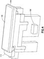
- the user depresses the top button portion 108 (which also depresses the bottom button portion 110) so that a button protrusion 138 (see Fig. 4 ) disengages from a first slider protrusion 140 (see Fig. 3 ), freeing the slider 122 to displace distally under the influence of the spring 126.
- an angled portion 144 of the slider 122 rotates the activation flipper 130 about its axis.
- the slider continues to displace distally under the influence of the spring 126 until a second slider protrusion 142 (see Fig. 3 ) contacts the release flipper 136 and maintains this position until the dose is delivered, as subsequently described in greater detail.
- the rotation of the activation flipper 130 causes the release gate 132 to slide laterally and disengage from the valve plunger 134. As subsequently described in greater detail, this frees the valve plunger 134 to move distally under the influence of a plunger spring 146 (see Fig. 5 ).
- a large, outer needle or first penetrator 148 creates a hole in two membranes that may each have a non-sterile outer surface. These membranes allow the surfaces inside the respective membranes to remain sterile even if the respective outside membranes may not be sterile.
- the outer needle 148 creates a hole in each of the (potentially) "contaminated" covers or membranes, which then allows a second penetrator or inner needle 150 to maintain sterility by preventing the inner needle 150 from contacting the non-sterile surfaces.
- a flexible cover 152 comes into contact with a barrier or membrane 154 disposed on a relatively rigid insert 156 disposed in a stopper 158.
- a front or distal portion 153 of the flexible cover 152 compresses or crumples or collapses. This allows the outer needle 148 to puncture or pierce both a barrier portion of the flexible cover 152 and the membrane 154 without contaminating the inner needle 150.
- the interior surfaces of the flexible cover 152 and the membrane 154 are sterilized during manufacturing prior to their assembly into the device 100, and remain sterile even though their respective outer surfaces may have become contaminated.
- the flexible cover 152, the first penetrator or outer needle 148, and the second penetrator or inner needle 150 form a valve sleeve assembly.
- an outer flange 160 of the outer needle 148 continues to crumple the distal portion 153 of the flexible cover 152 until the distal progress of the outer needle 148 is halted because an inner flange 162 has a diameter greater than that of the proximal portion of the insert 156.
- the valve plunger 134 continues to move distally, and a proximal portion 164 of the flexible cover (which has a thicker wall) begins to compress or crumple. This crumpling of the proximal portion 164 permits the inner needle 150 to distally advance through the bore of the outer needle 148 and contact an interior surface 159 of the stopper 158, which was previously sterilized during manufacture.
- the interior surface 159 of the stopper 158 forms a chamber and is covered by the insert 156 and the membrane 154. According to one embodiment, the interior surface 159 is sterilized prior to installation of the insert 156 and the membrane 154. According to another embodiment, the stopper 158, the insert 156, and the membrane 154 are sterilized substantially simultaneously. Subsequent to the stopper's sterilization, the sterility of its proximal end is maintained by the membrane 154. With continued distal movement of the valve plunger 134, the inner needle 150 pierces through the stopper 158 and initiates liquid medicament flow.
- valve plunger commences distal displacement of the stopper 158, and the flow of medicament continues (along with distal movement of the valve plunger 134) until the stopper reaches the distal end of the interior of the capped medicament barrel 106.
- the compression or crumpling or collapsing of the flexible cover 152 occurs in two steps; the distal portion 153 of the flexible cover (the area ahead of the outer flange 160 of the outer needle 148) crumples first, allowing the outer needle 148 to pierce both the distal end of the flexible cover 152 and the membrane 154 before the proximal portion 164 crumples.
- This bifurcated crumpling permits the inner needle 150 to secondarily move forward and pierce the stopper 158.
- the inner needle 150 will remain sterile without being contaminated.
- the pre-filled drug container can be installed into a previously assembled and sterilized infusion device without the need to maintain aseptic conditions until the drug container (e.g., medicament barrel 106) is installed into the infusion device.
- the drug container e.g., medicament barrel 106
- This allows the pre-filled drug container to be assembled by a pharmaceutical company or an end user without requiring the assembly environment to be aseptic.
- this permits the pre-filled medicament barrel 106 to be filled and inspected using industry-standard equipment and methods.
- Fig 7 is a bottom perspective view of portions of the device 100, in which the slider 122 is shown as being transparent for clarity.
- the valve plunger 134 has a cantilevered arm 166 with a vertical portion and a horizontal portion on its underside. These vertical and horizontal portions form a guide for a lower arm 168 of the release flipper 136. The contact between the guide and the lower arm 168 prevents rotation of the release flipper 136.
- the proximal end of the cantilevered arm 166 bypasses the lower arm 168, thereby freeing the release flipper 136 to rotate because of the contact of the second slider protrusion 142 (see Fig. 3 ) with an upper arm 170 (see Fig. 3 ) of the release flipper 136 and the continued bias of the spring 126.
- the release flipper 136 rotates sufficiently that the second slider protrusion 142 bypasses the upper arm 170 of the release flipper 136, the slider 122 continues its distal displacement.
- the continued distal displacement of the slider raises the proximal end of the needle arm 116 and withdraws the patient cannula (not shown).
- the continued distal displacement of the slider 122 also distally displaces the progress indicator 114, so that the user can see that the dosage is complete through the indicator window 112.
- the wall thickness of the flexible cover 173 is substantially constant.
- a two-shot molded part 172 acts as an elastomeric "spring" that is molded to the back of the outer needle 148.
- the outer needle 148 pierces the two sterile barriers before the inner needle proceeds forward into the sterile wall 159 of the septum 158.
- the elastomeric "spring" 172 provides the effect of the bifurcated crumpling of the embodiment in Figs. 5 and 6 , that is, the piercing by the outer needle 148 and the displacement of the inner needle 150 relative to the outer needle 148.
- the flexible cover 174 is a two-shot molded part, and has a crumpling portion 176 and a distal portion 178.
- the distal portion 178 has a membrane 180 sealed to the end of the distal portion.
- the membrane 180 and the membrane 154 abut each other prior to either membrane being pierced by the outer needle 148.
- the spacing between the two membranes 180, 154 can vary without departing from to the present invention's scope.
- the two membranes 180, 154 can be spaced apart or in full contact.
- the spacing of the two membranes affects the length and/or the travel of the outer needle 148 because the outer needle 148 pierces both membranes 180, 154.
- the space between the two membranes 180, 154 is minimized, or the membranes are in contact.
- the outer needle 148 rather than having to pierce the material that the remainder of the flexible cover 174 is made of (for example, rubber, or an elastomer, such as a medical-grade plastic), the outer needle 148 only needs to pierce the membrane(s) 180, 154. Accordingly, the force required to be produced by the spring 146 is reduced.
- the outer needle 182 is also connected to the elastomeric "spring" 183.
- the proximal flange 184 of the outer needle 182 extends radially farther outward than the embodiments of Figs. 8 and 9 .
- the proximal flange 184 contacts the interior of the flexible cover 186.
- the distal end of the outer needle includes one or more facets 188 to optimize the piercing ability of the outer needle 182.
- an antiseptic material is disposed in the space 190.
- the embodiment shown in Fig. 11 includes a flexible cover 200, which is made using a two-shot molding process.
- a proximal cover portion 202 is collapsible as previously described, and a distal cover portion 204 is joined to the proximal cover portion 202.
- a membrane 206 is disposed across a distal opening in the distal cover potion 204.
- a membrane 208 is disposed across a proximal end of a stopper insert 210.
- Material choices for the membranes 206 and 208 include a thin foil, or plastic films.
- the outer needle or penetrator or inserter 209 opens a sterile path for the inner needle 214 and then the inner needle 214 moves through the sterile path and punctures the stopper 216.
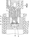
- the outer needle or penetrator 209 which is disposed on the distal end of a rubber spring 211, first penetrates both of the membranes 206 and 208 during distal displacement of the valve plunger 212. Then, as shown in the right side of Fig. 12 , the sterile inner needle 214 penetrates the stopper 216 to form the sterile connection with the medicament disposed within the medicament barrel 106.
- Figs. 13-16 Like the embodiment of Figs. 11 and 12 , the subsequently-described embodiments of Figs. 13-16 include a flexible cover having a membrane covering a distal opening thereof.
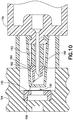
- the valve plunger 218 has a distal protrusion 220 to which the inner needle 228 is fixedly connected.
- the distal protrusion 220 contacts a proximal portion of the outer needle 222.
- the proximal portion of the outer needle 222 has a detent 224 with a shape that corresponds to a distal end 226 of the valve plunger's distal protrusion 220.
- the interaction of the detent 224 and the distal end 226 controls the force of collapse.
- the shape, the rigidity, and/or the fit between the detent 224 and the distal end 226 can affect the amount of force needed for the distal end 226 to displace relative to the detent 224.
- the detent 224 and the distal end 226 are slanted.
- valve plunger 218 and the outer needle 222 initially both displace distally without displacing relative to each other. This simultaneous but non-relative displacement continues until the outer needle 222 pierces the membranes 230 and 232 and the outer needle's proximal flange 234 prevents further displacement of the outer needle 222 relative to the stopper 236. Upon continued distal displacement of the valve plunger 218, the distal end 226 disengages from the detent 224, and the valve plunger 218 and the inner needle 228 displace distally relative to the outer needle 222 (and the stopper 236).
- the distal end 226 travels into a cavity 238 on the interior of the outer needle 222, and the inner needle 228 pierces the stopper 236 to form a sterile connection with the medicament disposed within the medicament barrel 106.
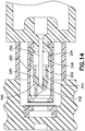
- the outer needle or penetrator 240 has a geometry designed to control its collapse during the penetration sequence. More specifically, the outer needle 240 has a distal penetrating portion 242, a central portion 244 with a first flange 246 at its distal end, and a proximal portion 248 with a second flange 250 at its distal end.
- the central portion 244 includes a central void 252
- the proximal portion 248 includes a proximal void 254.
- the combination of the lengths, outer diameters, and wall thicknesses of the central and proximal portions 244 and 248, along with the volumes of the central and proximal voids 252 and 254 provides a controlled collapse of the outer needle 240, to define the timing of the distal displacement of the inner needle 256 relative to the outer needle 240.
- the outer needle or penetrator 260 includes a distal penetrating portion 262, a central portion 264 with a flange 266 at its distal end, and a proximal portion 268.
- the proximal portion 268 tapers to have an increased diameter at its proximal end.
- the central portion 264 has a central void 270 and the proximal portion 268 has a proximal void 272.
- the combination of the lengths and wall thicknesses of the central and proximal portions 264 and 268, along with the taper angle of the proximal portion 268 and the volumes of the central and proximal voids 270 and 272 provides a controlled collapse of the outer needle 260, to define the timing of the distal displacement of the inner needle 274 relative to the outer needle 260.
- the outer needle or penetrator 280 includes a distal penetrating portion 282, a central portion 284 with a flange 286 at its distal end, and a proximal portion 288 that tapers to have an increased diameter at its proximal end.
- the tapered proximal portion 288 includes a proximal void 290.
- the central portion 284 is substantially solid.
- the length of the central portion 284 is decreased and the length of the proximal portion 288 is increased.
- the combination of the length, wall thickness, and taper angle of the proximal portion 288, along with the volume of the proximal void 290 provides a controlled collapse of the proximal portion 288 of the outer needle 280, to define the timing of the distal displacement of the inner needle 294 relative to the outer needle 280.
- the embodiments of Figs. 14-16 can optionally include in-molded springs disposed on the respective proximal ends of the outer needles 240, 260, and 280.
- the embodiments of Figs. 14-16 can optionally include lever arms disposed on the respective proximal ends of the outer needles 240, 260, and 280.
- Material choices for the outer needle or penetrator in embodiments of the present invention include metal, such as surgical stainless steel, and rigid plastic, such as polypropylene.
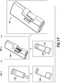
- Fig. 17 illustrates a method of inserting the medicament barrel 106 into a body 298 of the device 100.
- a user inserts the medicament barrel 106 into a holder 296.
- barrel 106 has been aseptically filled with medicament prior to insertion.
- the user then inserts the combined medicament barrel 106 and holder 196 into the body 298, thereby readying the device 100 for use.
- the holder is omitted and the barrel 106 is inserted directly into body 298 of device 100.
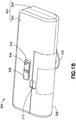
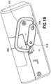
- Figs. 18 and 19 are perspective top and bottom perspective views of an infusion device 300 in accordance with another embodiment of the present invention
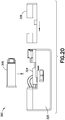
- Fig. 20 illustrates a method of inserting a medicament barrel into a body of the device 300.
- the device 300 is similar to the device 100 previously described.
- the device 300 includes a top cover 302, a bottom cover 304 (which together form a device body 305), a medicament barrel 306, a top button portion 308, a bottom button portion 310, and an indicator window 312, through which the user can see a progress indicator 314 to aid in determining the completion of the dose.
- aspects of the device 300 substantially similar to those of the device 100 will not be described in great detail.
- the medicament barrel displaces relative to a substantially fixed valve sleeve assembly, as subsequently described in greater detail.
- the valve sleeve assembly is moved to the opposite end of the medicament barrel, the function is still the same with the outer needle creating a sterile tunnel for the inner needle to move through to make the puncture and allow the medicament to flow.
- the device 300 includes a trolley 324 that is displaceably disposed in the device body, and a device cover or hood 326.
- a pharmaceutical company, end user, or other entity inserts the medicament barrel 306 into the trolley 324, and then locks the hood 326 onto the device body 305.
- the design of the device 300 permits medicament barrel loading 306 under conditions that are not aseptic, yet enables a sterile connection.
- the device 300 also includes a safety pin 316, a needle shield or cover 318, and a needle shield remover 320.
- the safety pin 316 extends from the bottom through the device 300, and up through the top and bottom button portions 308 and 310 to prevent the top button portion 308 from moving (and thereby prevent device activation) until the safety pin 316 is removed.
- the safety pin 316 and the needle shield 318 are both connected to the needle shield remover, which has a handle portion 322 for gripping.
- the needle shield remover which has a handle portion 322 for gripping.
- a user lifts and pulls the handle portion 322 to remove the needle shield 318 thereby uncovering the patient needle, disengaging the safety pin 316 from the top and bottom button portions 308 and 310, and readying the device 300 for activation.
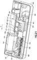
- the device 300 includes a needle actuator or slider 328, an activation flipper 330, and a release gate 332 that are similar in shape and function to the corresponding elements in the device 100.
- the device 300 additionally includes a plunger 334 and a release flipper 336.
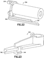
- the plunger 334 includes proximal hooks 339 for engaging the release gate 332, and a cantilevered arm 338 with a shelf 340.
- the release flipper 336 shown in Fig. 23 , includes a corresponding shelf 342 and plunger hook 344 that engage the shelf 340 to control the timing of events during operation of the device 300.
- a protrusion 347 on the bottom button portion 310 disengages from the a protrusion 348 on the needle actuator or slider 328, permitting the spring 346 to displace the needle actuator 328 distally (opposite to direction A) by a predetermined distance to an intermediate position in which a needle actuator catch 350 engages a needle actuator hook 352 on the release flipper 336 (best shown in Fig. 24 ).
- the engagement between the plunger's cantilevered arm 338 and the release flipper's shelf 342 and plunger hook 344 prevents the release flipper from rotating, and thus, maintains the engagement between the hook 352 and the catch 350, thereby maintaining the needle actuator's position.
- the distal end 329 of the needle actuator 328 rotates the activation flipper 330 counter-clockwise, thereby sliding the release gate 332 out of engagement with the plunger's proximal hooks 339, and permitting the plunger to displace distally under the force of a plunger spring 354 and displace displacing a stopper spacer 356 and a stopper 358.
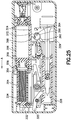
- Controlling movement of the trolley 324 is important because a premature movement of the medicament barrel 306 could puncture the membranes (394 and 406, subsequently described in greater detail) and create a sterility breach.
- the trolley 324 is selectively held in position by a trolley latch assembly 361.
- the distal end of the needle actuator 328 is adjacent to a trolley latch 360.
- the needle actuator 328 contacts the trolley latch 360 prior to activation.
- the needle actuator 328 and the trolley latch 360 are spaced apart.
- a trolley latch snap bridge 362 that rotatably supports a top post 364 of the trolley latch 360 is omitted from Fig. 25 for clarity.
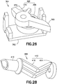
- the top post 364 extends through an annular cam portion 366 of a trolley stop 368, as shown in the bottom perspective view of the trolley latch assembly 361 in Fig. 26 .
- the trolley stop 368 includes a stop portion 370, which engages a recess or opening 372 in the trolley 324 prior to device activation to prevent the trolley from moving.
- the trolley latch 360 also includes a bottom protrusion 374 that prevents the trolley latch from freely rotating an amount sufficient to dislodge the stop portion 370 from the recess 372, and thus serves as a secondary safety to prevent trolley movement prior to activation.
- the distal end of the needle actuator 328 contacts and rotates the trolley latch 360 counter-clockwise with a force sufficient to preferably fracture and snap off the bottom protrusion 374 when it contacts a post in the bottom cover 304.
- the top post 364 interacts with the cam portion 366 to disengage the stop portion 370 from the recess 372, thereby permitting the trolley 324 to displace distally under the force of the plunger spring 354.
- the trolley 324 has proximal hooks 376 that engage a proximal rim or flange 378 of the medicament barrel 306. Because the medicament barrel 306 is sealed and filled with a substantially incompressible fluid, once the trolley stop 368 disengages from the trolley 324, the force of the plunger spring 354 acting on the stopper 358 (via the plunger 334 and the stopper spacer 356) displaces the trolley 324 distally due to the engagement between the proximal hooks 376 and the proximal rim 378.
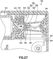
- a valve sleeve assembly 380 includes a two-part flexible sleeve 382 (which includes a barrier portion 384 and a flexible portion 386), a hollow first penetrator or outer needle 388, and a hollow second penetrator or inner needle 390.
- the barrier portion 384 includes a cap 392 disposed at the proximal end of the flexible portion 386, and a membrane 394 disposed across an opening at the proximal end of the cap 382.
- the distal end of the flexible portion 386 is connected to a needle shield holder 396, which is fixedly secured with the bottom cover 304.
- the inner needle 390 is fixedly secured to the shield holder 396, and is connected with the patient needle via a tube 398.
- the medicament barrel 306 has a sealing member or septum 400 disposed at its distal end, and a protective cap 402 and a cap 404 maintain the septum 400 at the distal end of the barrel 306.
- a barrier or membrane 406 is disposed across an opening at the distal end of the protective cap 402. Together, the septum 400, the protective cap 402, and the membrane 406 form a chamber 408 in fluid communication with the septum.
- at least the surface of the septum 400 exposed in the chamber 408 is sterile, and more preferably, the chamber 408 is sterile.
- the membrane 406 and the membrane 394 are disposed adjacent to each other. According to one embodiment, this is the relative position of the valve sleeve assembly 380 and the medicament barrel 306 prior to activation. Preferably, however, the membrane 406 and the membrane 394 are spaced apart prior to activation, and the state illustrated in Fig. 27 occurs subsequent to a predetermined trolley 324 displacement.
- the first penetrator or outer needle 388 includes a rigid, sharpened penetrating portion 410, and a collapsing portion 412.
- the collapsing portion includes a base 414 with a hole therethrough for the second or inner penetrator 390, and at least one, but preferably a pair of collapsible legs 416 connecting the base 414 and the penetrating portion 410.
- the penetrating portion includes a guide disposed therein to guide the displacement of the penetrating portion relative to the inner needle 390.
- the crush force required to bend the legs 416 is selected to be greater than the force required to collapse the flexible portion 386 of the flexible sleeve 382.
- This relative force profile ensures the timing of events so that the flexible portion 386 collapses prior to the legs 416 bending.
- this relative force profile ensures that the penetrating portion 410 pierces the membranes 394 and 406 prior to the legs bending and the penetrating portion 410 displacing relative to the inner needle 390 and exposing the proximal end of the inner needle, thereby maintaining the sterility of the inner needle 390.
- the proximal end of the inner needle 390 passes through the chamber 408 without contacting either of the membranes 394 and 406, and the force from the plunger spring 354 impales the septum 400 on the inner needle 390 so that the proximal end of the inner needle 390 pierces the septum 400. This creates a sterile connection between the medicament in the interior of the medicament barrel 306 and the patient needle, which is fluidly connected with the inner needle 390.
- Fig. 29 is a partial cross-sectional view of another double-puncture mechanism in accordance with an embodiment of the present invention.
- the embodiment of Fig. 29 is substantially similar to the embodiment of Fig. 27 , except for the first penetrator or outer needle 418.
- the first penetrator 418 includes a rigid, sharpened penetrating portion, but rather than a collapsing portion, instead includes one or more internal contact ribs 419, which can be, for example, insert-molded.
- the contact ribs 419 provide frictional resistance between the outer needle 418 and the inner needle 390, to ensure that the that the outer needle 418 pierces the membranes 394 and 406 prior to the inner needle 390 displacing relative to the outer needle 418.
- the force to collapse the flexible portion 386 is selected to be less than the force to displace the outer needle 418 relative to the inner needle 390.
- the plunger displaces further distally under the influence of the plunger spring 354, displacing the stopper spacer 356 and the stopper 358 (best shown in Fig. 25 ) relative to the medicament barrel 306 and dispensing the medicament.
- the cantilevered arm 338 disengages from the release flipper 336, thereby permitting the release flipper to rotate counter-clockwise as shown in Figs. 21 and 25 under the influence of the spring 346 pushing on the needle actuator 328.
- the hook 352 disengages from the catch 350, freeing the needle actuator 328 to displace distally under the influence of the spring 346, retract the patient needle, and displace the progress indicator 314 relative to the indicator window 312, to indicate that the dosage is complete.
- the embodiment of the device 300 permits a cartridge (including, for example, the plunger adapter 356, the stopper 358, the medicament barrel 306, the septum 400, the protective cap 402, and the cap 404) to be inserted into the remainder of the device under conditions that are not aseptic, because the sterility of the medicament flow path is ensured by the sealed valve sleeve assembly.
- the cartridge can be sterilized via an ethylene oxide (EtO) sterilization process to avoid yellowing the barrel, and the remainder of the device 300 can be sterilized via gamma irradiation.
- EtO ethylene oxide
- infusion and injection devices for human use
- other applications can be realized, for example, infusion or injection devices for animals, devices for re-hydrating lyophilized medicament, devices for mixing fluids, such as fluid medications, and devices for re-hydrating freeze-dried food.
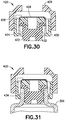
- Figs. 30-32 are partial cross-sectional views illustrating a sealing assembly 420 and a process of employing the sealing assembly 420 to seal an end of the medicament container or medicament barrel 306.
- the sealing assembly 420 includes a septum 422, a protective cap 424, a sealing membrane 426, and an outer cap 428, as shown in Fig. 30 .
- the cap 428 includes guide features 429 that aid in positioning the end of the flexible sleeve assembly 380 to be adjacent to the membrane 426.
- the manufacturer applies the membrane 426 to cover an opening in the protective cap 424, and inserts the protective cap 424 into a recess in the septum 422 to form an intermediate assembly.
- the chamber formed by the septum 422, the protective cap 424, and the membrane 426 is closed, but not yet sterile.
- the septum 422, the protective cap 424, and the membrane 426 can be sterilized, using, for example, a gamma irradiation technique.
- the manufacturer places the cap 428 onto an end of the protective cap 424 to form the sealing assembly 420.
- the manufacturer then inserts the sealing assembly 420 onto an end of a medicament barrel 306 so that the septum 422 seats inside a tip at the end of the barrel 306 and the protective cap 424 secures the subassembly around an outside of the barrel tip.
- one or more protective cap cantilevered arms 430 each having a hook 432, slide around an exterior of the barrel tip until the hook 432 bypasses an annular catch 434 on the barrel 306. Subsequently, as shown in Fig.
- the manufacturer slides the outer cap 428 down around the protective cap 424, which prevents the hooks 432 from disengaging from the annular barrel catch 434, and thereby secures the sealing assembly 420 to the end of the barrel 306.
- the outer cap 428 compresses the protective cap 444.
- the combination of the sealing assembly 420 and the barrel 306 can be sterilized together using, for example, via an EtO sterilization process.
- Fig. 33 illustrates another embodiment of a sealing assembly 440 including a septum 442, a protective cap 444, a sealing membrane 446, and an outer cap 448.
- the sealing assembly 440 is substantially similar to the sealing assembly 420, except that the guide features are disposed on the protective cap 444, not on the outer cap 448.
- the protective cap 444 includes an annular feature 450 on an exterior surface
- the cap 448 includes a pair of annular recesses 452 and 454 on an interior surface.
- the annular feature 450 engages the first recess 454 to maintain the relative positions of the intermediate assembly and the cap 448 as the sealing assembly 440 is inserted onto the end of the barrel 306.
- the manufacturer slides the outer cap 448 relative to the protective cap 444 so that the annular feature 450 engages the second recess 452 (as shown in Fig. 33 ) to secure the sealing assembly 420 to the barrel tip.
- the protective cap 444 has an additional annular feature 450 so that when the manufacturer slides the outer cap 448 relative to the protective cap 444 to secure the sealing assembly 420 to the barrel tip, the annular features 450 respectively engage both of the recesses 452 and 454.
Description
- This application claims priority under 35 USC §119(e) from
U.S. Provisional Patent Application Serial No. 61/910,373, filed on December 1, 2013 - The present invention relates to methods and devices for making a sterile connection, and more particularly, to methods and devices for making a sterile connection with a medicament source.
- Drug delivery devices in the form of infusers are known in the prior art for administering medicament to a patient. Infusers are intended for mounting onto a patient's skin for self-administration of a medicament. Activation of the infuser not only provides for injection of a needle into a patient's skin, but also to cause auto-drive of a plunger to drive medicament into the patient via the injected needle. Typical infuser constructions have the needle fixed to the reservoir. For example,
U.S. Patent No. 5,858,001 to Tsals et al. , discloses an infuser that is activated through swivel displacement of a reservoir-containing body. A needle is fixed to the body to move therewith so that the swivel displacement of the body also causes the needle to penetrate the patient's skin. Other types of infusers are known, including those which use standard needle-mounted syringe barrels. With many infusers, the ability to control the insertion of the needle independent of the administration of medicament is limited. -
U.S. Patent No. 5,290,254 to Vaillancourt discloses a shielded cannula assembly that includes a tubular shield mounted over a cannula. The shield includes a resilient collapsible portion that collapses in an accordion-like manner when a longitudinal force is imposed on the shield. -
U.S. Patent No. 5,685,866 to Lopez discloses a needleless valve with a generally tubular body defining an internal cavity. The valve includes a hollow spike with a closed tip and a hole located in the tip. The spike is seated inside the cavity so that the tip is below the proximal end of the body. An annular support cuff is connected to the spike and seals off a portion of the cavity to define an upper portion of the cavity that includes the tip. The valve also includes a plastic, resilient silicone seal that fills the upper portion of cavity and the body opening, and covers the tip of the spike to present a flush surface. -
U.S. Patent Publication No. 2010/00022953 -
PCT Publication WO 2011/146166 discloses an infuser in which activation of an actuator causes a spring to move a stopper in a reservoir from a first position toward a second position, and also causes a needle driver to displace a patient needle from a first state toward a second state. The needle moves relative to the reservoir, and separately from the stopper. - In addition, with medical devices, such as syringes and infusion devices, making a sterile connection with a medicament storage device, such as a medicament vial, generally necessitates maintaining the sterility of all parts of the connection, or making the parts of the connection sterile immediately prior to making the connection. Improvements in the equipment and/or the process of making a sterile connection with a medicament storage device are desirable.
- Accordingly, it is an aspect of the present invention to provide an improved apparatus and method for making a sterile connection.
- The foregoing and/or other aspects of the present invention are achieved by providing an apparatus for making a sterile connection, including a container, a sealing member sealing a first end of the container, a barrier sealing a chamber in fluid communication with the sealing member, and a valve sleeve assembly. The valve assembly includes a flexible sleeve having a barrier portion at an end of the flexible sleeve, a hollow first penetrator adapted to displace relative to the flexible sleeve, and a hollow second penetrator at least partially disposed within the first penetrator and adapted to displace relative to the first penetrator and the flexible sleeve. An interior of the flexible sleeve is sterile. In an initial state, the flexible sleeve encloses the first penetrator and a penetrating end of the second penetrator. One of the container and the valve sleeve assembly is adapted to displace relative to the remaining one of the container and the valve sleeve assembly. The flexible sleeve is adapted to collapse, thereby displacing the outer penetrator relative to the flexible sleeve to pierce the barrier portion and the barrier. Upon further relative displacement between the container and the valve sleeve assembly, subsequent to the piercing of the barrier portion and the barrier, the second penetrator is adapted displace relative to the first penetrator, through the chamber, to pierce the sealing member to create a sterile connection with the interior of the container.
- The foregoing and other aspects of the present invention are also achieved by providing a method for creating a sterile connection with a fluid in a container. The container has a sealing member sealing a first end of the container, and a barrier sealing a chamber in fluid communication with the sealing member. The method includes providing a valve sleeve assembly that includes a flexible sleeve having a barrier portion at an end of the flexible sleeve, a hollow first penetrator disposed within the flexible sleeve, and a hollow second penetrator at least partially disposed within the first penetrator. An interior of the flexible sleeve is sterile. The method also includes piercing the barrier portion and the barrier with the first penetrator, and displacing the second penetrator relative to the first penetrator and the sealing member to pierce the sealing member and establish the sterile connection with an interior of the container
- Additional and/or other aspects and advantages of the present invention will be set forth in the description that follows, or will be apparent from the description, or may be learned by practice of the invention.
- The above and/or other aspects and advantages of embodiments of the invention will be more readily appreciated from the following detailed description in conjunction with the accompanying drawings, in which:
-
Fig. 1 is a top perspective view of an infusion device in accordance with an embodiment of the present invention; -
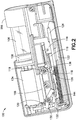
Fig. 2 is a top perspective view of the device ofFig. 1 with a several elements removed for clarity; -
Fig. 3 is a perspective view of elements of the device ofFig. 1 ; -
Fig. 4 is a perspective view of a button assembly of the device ofFig. 1 ; -
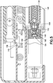
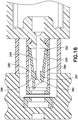
Fig. 5 is a partial cross-sectional view of a double-puncture mechanism in accordance with an embodiment of the present invention; -
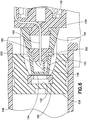
Fig. 6 is an enlarged, partial cross-sectional view of the mechanism ofFig. 5 ; -
Fig 7 is a bottom perspective view of another double-puncture mechanism in accordance with an embodiment of the present invention; -
Fig. 8 is a partial cross-sectional view of another double-puncture mechanism in accordance with an embodiment of the present invention; -
Fig. 9 is a partial cross-sectional view of another double-puncture mechanism in accordance with an embodiment of the present invention; -
Fig. 10 is a partial cross-sectional view of the double-puncture mechanism in accordance with the embodiment ofFig. 8 ; -
Fig. 11 is a partial cross-sectional view of another double-puncture mechanism in accordance with an embodiment of the present invention; -
Fig. 12 is a cross-sectional view of operation of the mechanism ofFig. 11 ; -
Fig. 13 is a partial cross-sectional view of another double-puncture mechanism in accordance with an embodiment of the present invention; -
Fig. 14 is a partial cross-sectional view of another double-puncture mechanism in accordance with an embodiment of the present invention; -
Fig. 15 is a partial cross-sectional view of another double-puncture mechanism in accordance with an embodiment of the present invention; -
Fig. 16 is a partial cross-sectional view of another double-puncture mechanism in accordance with an embodiment of the present invention; -
Fig. 17 illustrates a method of inserting a medicament barrel into a body of the device ofFig. 1 ; -
Fig. 18 is a top perspective view of an infusion device in accordance with an embodiment of the present invention; -
Fig. 19 is a bottom perspective view of the infusion device ofFig. 18 ; -
Fig. 20 illustrates a method of inserting a medicament barrel into a body of the device ofFig 18 ; -
Fig. 21 is a perspective view of the device ofFig. 18 with a top cover and a hood removed for clarity; -
Fig. 22 is a perspective view of a plunger of the device ofFig. 18 ; -
Fig. 23 is a perspective view of a release flipper of the device ofFig. 18 ; -
Fig. 24 is a bottom perspective view of top and bottom button portions and a needle actuator of the device ofFig. 18 and the release flipper ofFig. 23 ; -
Fig. 25 is a cross-sectional view of the device ofFig. 18 prior to activation; -
Fig. 26 is a bottom perspective view of a trolley latch assembly of the device ofFig. 18 ; -
Fig. 27 is a partial cross-sectional view of the device ofFig. 18 ; -
Fig. 28 is a perspective view of a first penetrator of the device ofFig. 18 ; -
Fig. 29 is a partial cross-sectional view of another double-puncture mechanism in accordance with an embodiment of the present invention; -
Figs. 30-32 are partial cross-sectional views illustrating a sealing assembly and a process of employing the sealing assembly to seal an end of a medicament container of the device ofFig. 18 ; and -
Fig. 33 is a partial cross-sectional view of another sealing assembly in accordance with an embodiment of the present invention. - Detailed reference will now be made to embodiments of the present invention, which are illustrated in the accompanying drawings, wherein like reference numerals refer to like elements throughout. The described embodiments exemplify, but do not limit, the present invention by referring to the drawings.
- It will be understood by one skilled in the art that this disclosure is not limited in its application to the details of construction and the arrangement of components set forth in the following description or illustrated in the drawings. The embodiments herein are capable of other embodiments, and capable of being practiced or carried out in various ways. Also, it will be understood that the phraseology and terminology used is for description and should not be regarded as limiting. The use of words such as "including," "comprising," or "having" and variations thereof herein is meant to encompass the items listed thereafter and equivalents thereof as well as additional items. Unless limited otherwise, the terms "connected," "coupled," and "mounted," and variations thereof are used broadly and encompass direct and indirect connections, couplings, and mountings. In addition, the terms "connected" and "coupled" and variations thereof are not restricted to physical or mechanical connections or couplings. Further, terms such as up, down, bottom, and top are relative, and are employed to aid illustration, but are not limiting.
- The methods and devices of embodiments of the invention include both bolus injection or "injection" and infusion or "infuser" delivery of drugs and other substances to humans or animals subjects. Using the present invention, pharmaceutical compounds may be administered as a bolus injection, or by infusion. As used herein, the term "bolus injection" is intended to mean an amount that is delivered within a time period of less than ten (10) minutes. "Infusion" is intended to mean the delivery of a substance over a time period greater than ten (10) minutes. It is understood that bolus administration or delivery can be carried out with rate controlling means or have no specific rate controlling means. Such rate controlling means include programmed delivery of substances, for example, in a pulsatile manner, by way of example, substances administered via a bolus followed by a short or long term infusion. A bolus dose is a single dose delivered in a single volume unit over a relatively brief period of time, typically less than about 10 minutes. Infusion administration comprises administering a fluid at a selected rate that may be constant or variable, over a relatively more extended time period, typically greater than about 10 minutes
- Although the following embodiments are directed to infusion devices, it will be understood by those skilled in the art that embodiments of the present invention are not limited to infusion devices, and instead, can include injectors, or any type of device for making a sterile connection with a storage device (such as a medicament storage device). For brevity, however, the illustrated embodiments are generally referred to as infusion devices.
-
Fig. 1 is a top perspective view of an infusion device orinfuser 100 for infusing a medicament into a patient. Although a user other than a medicament recipient (for example, a health care professional) can use thedevice 100, for brevity, the term "user" will be employed to refer to a patient and/or other user. Thedevice 100 includes atop cover 102, abottom cover 104, amedicament barrel 106, atop button portion 108, and abottom button portion 110. As described in greater detail below, thetop cover 102 prevents thetop button portion 108 from being depressed until a user slides the button longitudinally (proximally, or to the left inFig. 1 ). Thedevice 100 also includes anindicator window 112, through which the user can see aprogress indicator 114 to aid in determining the completion of the dose. -
Figs 2 and3 each have several elements omitted for clarity. Referring toFigs. 2 and3 , thedevice 100 includes aneedle arm 116 with aport 118 and a patient cannula, such as a needle (not shown) disposed at a free end thereof. Theport 118 is connected by tubing (not shown) to aplunger port 120, which is connected to a needle described in greater detail below. Thedevice 100 also includes a needle actuator orslider 122. Theprogress indicator 114 is connected to theslider 122 and moves distally with theslider 122. - A
spring shaft 124 guides aspring 126 that biases theslider 122 distally. Thespring 126 bears against aspring pusher 128, which is fixedly connected to theslider 122. - The
device 100 also includes anactivation flipper 130, arelease gate 132, avalve plunger 134, and arelease flipper 136. Theactivation flipper 130 and the release flipper rotate about substantially parallel axes. These axes are substantially perpendicular to thebottom cover 104. - Referring to
Figs. 1-4 , to activate thedevice 100, a user slides thetop button portion 108 proximally until it aligns with an opening in thetop cover 102. In other words, the user slides thetop button portion 108 until a cantileveredportion 109 clears the edge of the opening. Then, the user depresses the top button portion 108 (which also depresses the bottom button portion 110) so that a button protrusion 138 (seeFig. 4 ) disengages from a first slider protrusion 140 (seeFig. 3 ), freeing theslider 122 to displace distally under the influence of thespring 126. - As the
slider 122 moves distally, anangled portion 144 of theslider 122 rotates theactivation flipper 130 about its axis. The slider continues to displace distally under the influence of thespring 126 until a second slider protrusion 142 (seeFig. 3 ) contacts therelease flipper 136 and maintains this position until the dose is delivered, as subsequently described in greater detail. The rotation of theactivation flipper 130 causes therelease gate 132 to slide laterally and disengage from thevalve plunger 134. As subsequently described in greater detail, this frees thevalve plunger 134 to move distally under the influence of a plunger spring 146 (seeFig. 5 ). - In general, in the described embodiments of the
device 100, there are two needles for creating a sterile connection with themedicament barrel 106. For example, a large, outer needle orfirst penetrator 148 creates a hole in two membranes that may each have a non-sterile outer surface. These membranes allow the surfaces inside the respective membranes to remain sterile even if the respective outside membranes may not be sterile. Theouter needle 148 creates a hole in each of the (potentially) "contaminated" covers or membranes, which then allows a second penetrator orinner needle 150 to maintain sterility by preventing theinner needle 150 from contacting the non-sterile surfaces. - More specifically, in the embodiment shown in
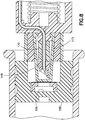
Figs. 5 and6 , as thevalve plunger 134 displaces distally under the influence of theplunger spring 146, aflexible cover 152 comes into contact with a barrier ormembrane 154 disposed on a relativelyrigid insert 156 disposed in astopper 158. With continued distal movement of thevalve plunger 134, a front ordistal portion 153 of theflexible cover 152 compresses or crumples or collapses. This allows theouter needle 148 to puncture or pierce both a barrier portion of theflexible cover 152 and themembrane 154 without contaminating theinner needle 150. The interior surfaces of theflexible cover 152 and themembrane 154 are sterilized during manufacturing prior to their assembly into thedevice 100, and remain sterile even though their respective outer surfaces may have become contaminated. Collectively, theflexible cover 152, the first penetrator orouter needle 148, and the second penetrator orinner needle 150 form a valve sleeve assembly. - As the distal displacement of the
valve plunger 134 continues anouter flange 160 of theouter needle 148 continues to crumple thedistal portion 153 of theflexible cover 152 until the distal progress of theouter needle 148 is halted because aninner flange 162 has a diameter greater than that of the proximal portion of theinsert 156. At this point, thevalve plunger 134 continues to move distally, and aproximal portion 164 of the flexible cover (which has a thicker wall) begins to compress or crumple. This crumpling of theproximal portion 164 permits theinner needle 150 to distally advance through the bore of theouter needle 148 and contact aninterior surface 159 of thestopper 158, which was previously sterilized during manufacture. - The
interior surface 159 of thestopper 158 forms a chamber and is covered by theinsert 156 and themembrane 154. According to one embodiment, theinterior surface 159 is sterilized prior to installation of theinsert 156 and themembrane 154. According to another embodiment, thestopper 158, theinsert 156, and themembrane 154 are sterilized substantially simultaneously. Subsequent to the stopper's sterilization, the sterility of its proximal end is maintained by themembrane 154. With continued distal movement of thevalve plunger 134, theinner needle 150 pierces through thestopper 158 and initiates liquid medicament flow. Continued distal displacement of the valve plunger commences distal displacement of thestopper 158, and the flow of medicament continues (along with distal movement of the valve plunger 134) until the stopper reaches the distal end of the interior of the cappedmedicament barrel 106. - In this embodiment, the compression or crumpling or collapsing of the
flexible cover 152 occurs in two steps; thedistal portion 153 of the flexible cover (the area ahead of theouter flange 160 of the outer needle 148) crumples first, allowing theouter needle 148 to pierce both the distal end of theflexible cover 152 and themembrane 154 before theproximal portion 164 crumples. This bifurcated crumpling permits theinner needle 150 to secondarily move forward and pierce thestopper 158. When the device operates in the specified manner, theinner needle 150 will remain sterile without being contaminated. - By permitting two potentially contaminated surfaces to be punctured with the
outer needle 148 while maintaining the sterility of theinner needle 150, the pre-filled drug container can be installed into a previously assembled and sterilized infusion device without the need to maintain aseptic conditions until the drug container (e.g., medicament barrel 106) is installed into the infusion device. This allows the pre-filled drug container to be assembled by a pharmaceutical company or an end user without requiring the assembly environment to be aseptic. In addition, this permits thepre-filled medicament barrel 106 to be filled and inspected using industry-standard equipment and methods. -
Fig 7 is a bottom perspective view of portions of thedevice 100, in which theslider 122 is shown as being transparent for clarity. One skilled in the art will appreciate that the opacity of theslider 122 can vary without departing from the present invention's scope. Referring toFigs. 2 and7 , thevalve plunger 134 has a cantileveredarm 166 with a vertical portion and a horizontal portion on its underside. These vertical and horizontal portions form a guide for alower arm 168 of therelease flipper 136. The contact between the guide and thelower arm 168 prevents rotation of therelease flipper 136. - As the
valve plunger 134 finishes its distal travel to end flow of the medicament, the proximal end of the cantileveredarm 166 bypasses thelower arm 168, thereby freeing therelease flipper 136 to rotate because of the contact of the second slider protrusion 142 (seeFig. 3 ) with an upper arm 170 (seeFig. 3 ) of therelease flipper 136 and the continued bias of thespring 126. Once therelease flipper 136 rotates sufficiently that thesecond slider protrusion 142 bypasses theupper arm 170 of therelease flipper 136, theslider 122 continues its distal displacement. Because of contact ofwings 119 at the proximal end of theneedle arm 116 with a ramp 125 of a track on the interior of theslider 122, the continued distal displacement of the slider raises the proximal end of theneedle arm 116 and withdraws the patient cannula (not shown). The continued distal displacement of theslider 122 also distally displaces theprogress indicator 114, so that the user can see that the dosage is complete through theindicator window 112. - In an alternative double puncture embodiment in
Fig. 8 , the wall thickness of theflexible cover 173 is substantially constant. In this embodiment, a two-shot moldedpart 172 acts as an elastomeric "spring" that is molded to the back of theouter needle 148. As in the embodiment ofFigs. 5 and6 , theouter needle 148 pierces the two sterile barriers before the inner needle proceeds forward into thesterile wall 159 of theseptum 158. In concert with the crumpling of theflexible cover 173, the elastomeric "spring" 172 provides the effect of the bifurcated crumpling of the embodiment inFigs. 5 and6 , that is, the piercing by theouter needle 148 and the displacement of theinner needle 150 relative to theouter needle 148. - In another alternative embodiment in
Fig. 9 , theflexible cover 174 is a two-shot molded part, and has a crumplingportion 176 and adistal portion 178. Thedistal portion 178 has amembrane 180 sealed to the end of the distal portion. As shown inFig. 9 , themembrane 180 and themembrane 154 abut each other prior to either membrane being pierced by theouter needle 148. The spacing between the twomembranes membranes outer needle 148 because theouter needle 148 pierces bothmembranes membranes - In this embodiment, rather than having to pierce the material that the remainder of the
flexible cover 174 is made of (for example, rubber, or an elastomer, such as a medical-grade plastic), theouter needle 148 only needs to pierce the membrane(s) 180, 154. Accordingly, the force required to be produced by thespring 146 is reduced. - Like the embodiments of
Figs. 8 and9 , in the embodiment inFig. 10 , theouter needle 182 is also connected to the elastomeric "spring" 183. In contrast, however, theproximal flange 184 of theouter needle 182 extends radially farther outward than the embodiments ofFigs. 8 and9 . According to one embodiment, theproximal flange 184 contacts the interior of theflexible cover 186. Additionally, the distal end of the outer needle includes one ormore facets 188 to optimize the piercing ability of theouter needle 182. - Moreover, in contrast to previously-described embodiments, there is a
greater space 190 between the distal end of theflexible cover 186 and themembrane 192 disposed at the proximal end of thestopper 194 prior to distal displacement of thevalve plunger 134. According to one embodiment, an antiseptic material is disposed in thespace 190. - Similar to the embodiment of
Fig. 9 in many respects, the embodiment shown inFig. 11 includes aflexible cover 200, which is made using a two-shot molding process. Aproximal cover portion 202 is collapsible as previously described, and adistal cover portion 204 is joined to theproximal cover portion 202. Amembrane 206 is disposed across a distal opening in thedistal cover potion 204. In addition, amembrane 208 is disposed across a proximal end of astopper insert 210. Material choices for themembranes 206 and 208 (and other previously-described membranes) include a thin foil, or plastic films. - Briefly, in operation, the outer needle or penetrator or
inserter 209 opens a sterile path for theinner needle 214 and then theinner needle 214 moves through the sterile path and punctures thestopper 216. In greater detail, as shown in the left side ofFig. 12 , the outer needle orpenetrator 209, which is disposed on the distal end of arubber spring 211, first penetrates both of themembranes valve plunger 212. Then, as shown in the right side ofFig. 12 , the sterileinner needle 214 penetrates thestopper 216 to form the sterile connection with the medicament disposed within themedicament barrel 106. - Like the embodiment of
Figs. 11 and12 , the subsequently-described embodiments ofFigs. 13-16 include a flexible cover having a membrane covering a distal opening thereof. - In the embodiment shown in
Fig. 13 , thevalve plunger 218 has adistal protrusion 220 to which theinner needle 228 is fixedly connected. Thedistal protrusion 220 contacts a proximal portion of theouter needle 222. The proximal portion of theouter needle 222 has adetent 224 with a shape that corresponds to adistal end 226 of the valve plunger'sdistal protrusion 220. The interaction of thedetent 224 and thedistal end 226 controls the force of collapse. For example, the shape, the rigidity, and/or the fit between thedetent 224 and thedistal end 226 can affect the amount of force needed for thedistal end 226 to displace relative to thedetent 224. According to one embodiment, thedetent 224 and thedistal end 226 are slanted. - In operation, the
valve plunger 218 and theouter needle 222 initially both displace distally without displacing relative to each other. This simultaneous but non-relative displacement continues until theouter needle 222 pierces themembranes proximal flange 234 prevents further displacement of theouter needle 222 relative to thestopper 236. Upon continued distal displacement of thevalve plunger 218, thedistal end 226 disengages from thedetent 224, and thevalve plunger 218 and theinner needle 228 displace distally relative to the outer needle 222 (and the stopper 236). During this continued distal displacement, thedistal end 226 travels into acavity 238 on the interior of theouter needle 222, and theinner needle 228 pierces thestopper 236 to form a sterile connection with the medicament disposed within themedicament barrel 106. - In the embodiment in
Fig. 14 , the outer needle orpenetrator 240 has a geometry designed to control its collapse during the penetration sequence. More specifically, theouter needle 240 has a distal penetratingportion 242, acentral portion 244 with afirst flange 246 at its distal end, and aproximal portion 248 with asecond flange 250 at its distal end. Thecentral portion 244 includes acentral void 252, and theproximal portion 248 includes aproximal void 254. The combination of the lengths, outer diameters, and wall thicknesses of the central andproximal portions proximal voids outer needle 240, to define the timing of the distal displacement of theinner needle 256 relative to theouter needle 240. - Similarly, in the embodiment shown in
Fig. 15 , the outer needle orpenetrator 260 includes a distal penetratingportion 262, acentral portion 264 with aflange 266 at its distal end, and aproximal portion 268. In contrast to theproximal portion 248 of the embodiment ofFig. 14 , which is substantially cylindrical, theproximal portion 268 tapers to have an increased diameter at its proximal end. Thecentral portion 264 has acentral void 270 and theproximal portion 268 has aproximal void 272. The combination of the lengths and wall thicknesses of the central andproximal portions proximal portion 268 and the volumes of the central andproximal voids outer needle 260, to define the timing of the distal displacement of theinner needle 274 relative to theouter needle 260. - In the embodiment shown in
Fig. 16 , similar to the embodiment shown inFig. 15 , the outer needle orpenetrator 280 includes a distal penetratingportion 282, acentral portion 284 with aflange 286 at its distal end, and aproximal portion 288 that tapers to have an increased diameter at its proximal end. The taperedproximal portion 288 includes aproximal void 290. In contrast to the embodiment ofFig. 15 , however, except for acentral passage 292 for theinner needle 294, thecentral portion 284 is substantially solid. In addition, compared to the embodiments ofFigs. 14 and15 , the length of thecentral portion 284 is decreased and the length of theproximal portion 288 is increased. The combination of the length, wall thickness, and taper angle of theproximal portion 288, along with the volume of theproximal void 290 provides a controlled collapse of theproximal portion 288 of theouter needle 280, to define the timing of the distal displacement of theinner needle 294 relative to theouter needle 280. - Although not shown, the embodiments of
Figs. 14-16 can optionally include in-molded springs disposed on the respective proximal ends of theouter needles Figs. 14-16 can optionally include lever arms disposed on the respective proximal ends of theouter needles - Material choices for the outer needle or penetrator in embodiments of the present invention include metal, such as surgical stainless steel, and rigid plastic, such as polypropylene.
-
Fig. 17 illustrates a method of inserting themedicament barrel 106 into abody 298 of thedevice 100. As shown on the left side ofFig. 17 , initially, a user inserts themedicament barrel 106 into aholder 296. Preferably,barrel 106 has been aseptically filled with medicament prior to insertion. Subsequently, as shown in the middle ofFig. 17 , the user then inserts the combinedmedicament barrel 106 and holder 196 into thebody 298, thereby readying thedevice 100 for use. Optionally the holder is omitted and thebarrel 106 is inserted directly intobody 298 ofdevice 100. -
Figs. 18 and19 are perspective top and bottom perspective views of aninfusion device 300 in accordance with another embodiment of the present invention, andFig. 20 illustrates a method of inserting a medicament barrel into a body of thedevice 300. In many respects, thedevice 300 is similar to thedevice 100 previously described. For example, thedevice 300 includes atop cover 302, a bottom cover 304 (which together form a device body 305), amedicament barrel 306, atop button portion 308, abottom button portion 310, and anindicator window 312, through which the user can see aprogress indicator 314 to aid in determining the completion of the dose. For brevity, aspects of thedevice 300 substantially similar to those of thedevice 100 will not be described in great detail. - But in contrast to the
device 100 in which the valve sleeve assembly displaces relative to a substantially fixed medicament barrel, in thedevice 300, the medicament barrel displaces relative to a substantially fixed valve sleeve assembly, as subsequently described in greater detail. Although the valve sleeve assembly is moved to the opposite end of the medicament barrel, the function is still the same with the outer needle creating a sterile tunnel for the inner needle to move through to make the puncture and allow the medicament to flow. - In addition to the above-noted features, the
device 300 includes atrolley 324 that is displaceably disposed in the device body, and a device cover orhood 326. Referring toFig. 20 , to load themedicament barrel 306 into thedevice body 305, a pharmaceutical company, end user, or other entity (for brevity, a user) inserts themedicament barrel 306 into thetrolley 324, and then locks thehood 326 onto thedevice body 305. As subsequently described in greater detail, the design of thedevice 300 permits medicament barrel loading 306 under conditions that are not aseptic, yet enables a sterile connection. - Referring back to
Figs. 18 and19 , thedevice 300 also includes asafety pin 316, a needle shield or cover 318, and aneedle shield remover 320. In a safety configuration, thesafety pin 316 extends from the bottom through thedevice 300, and up through the top andbottom button portions top button portion 308 from moving (and thereby prevent device activation) until thesafety pin 316 is removed. - According to one embodiment, the
safety pin 316 and theneedle shield 318 are both connected to the needle shield remover, which has ahandle portion 322 for gripping. In operation, a user lifts and pulls thehandle portion 322 to remove theneedle shield 318 thereby uncovering the patient needle, disengaging thesafety pin 316 from the top andbottom button portions device 300 for activation. - As shown in
Fig. 21 , thedevice 300 includes a needle actuator orslider 328, anactivation flipper 330, and arelease gate 332 that are similar in shape and function to the corresponding elements in thedevice 100. Thedevice 300 additionally includes aplunger 334 and arelease flipper 336. As shown inFigs. 22 , theplunger 334 includesproximal hooks 339 for engaging therelease gate 332, and acantilevered arm 338 with ashelf 340. Therelease flipper 336, shown inFig. 23 , includes acorresponding shelf 342 andplunger hook 344 that engage theshelf 340 to control the timing of events during operation of thedevice 300. - More specifically, once a user activates the
device 300 by sliding thetop button portion 308 in a proximal direction (direction A shown inFig. 21 ), and then depressing bothbutton portions protrusion 347 on thebottom button portion 310 disengages from the aprotrusion 348 on the needle actuator orslider 328, permitting thespring 346 to displace theneedle actuator 328 distally (opposite to direction A) by a predetermined distance to an intermediate position in which aneedle actuator catch 350 engages aneedle actuator hook 352 on the release flipper 336 (best shown inFig. 24 ). The engagement between the plunger'scantilevered arm 338 and the release flipper'sshelf 342 andplunger hook 344 prevents the release flipper from rotating, and thus, maintains the engagement between thehook 352 and thecatch 350, thereby maintaining the needle actuator's position. - Additionally, as the
needle actuator 328 displaces to the intermediate position, thedistal end 329 of theneedle actuator 328 rotates theactivation flipper 330 counter-clockwise, thereby sliding therelease gate 332 out of engagement with the plunger's proximal hooks 339, and permitting the plunger to displace distally under the force of aplunger spring 354 and displace displacing astopper spacer 356 and astopper 358. - Controlling movement of the
trolley 324 is important because a premature movement of themedicament barrel 306 could puncture the membranes (394 and 406, subsequently described in greater detail) and create a sterility breach. To control the movement of thetrolley 324 and assure that it does not move until the desired time, thetrolley 324 is selectively held in position by atrolley latch assembly 361. As shown inFig. 25 , prior to activation, the distal end of theneedle actuator 328 is adjacent to atrolley latch 360. According to the embodiment shown inFig. 25 , theneedle actuator 328 contacts thetrolley latch 360 prior to activation. According to another embodiment, however, prior to activation, theneedle actuator 328 and thetrolley latch 360 are spaced apart. Although shown inFigs. 21 and26 , a trolleylatch snap bridge 362 that rotatably supports atop post 364 of thetrolley latch 360 is omitted fromFig. 25 for clarity. Thetop post 364 extends through anannular cam portion 366 of atrolley stop 368, as shown in the bottom perspective view of thetrolley latch assembly 361 inFig. 26 . - In addition to the
cam portion 366, thetrolley stop 368 includes astop portion 370, which engages a recess or opening 372 in thetrolley 324 prior to device activation to prevent the trolley from moving. Thetrolley latch 360 also includes abottom protrusion 374 that prevents the trolley latch from freely rotating an amount sufficient to dislodge thestop portion 370 from therecess 372, and thus serves as a secondary safety to prevent trolley movement prior to activation. - Subsequent to activation, as the
needle actuator 328 displaces to the intermediate position under the force of thespring 346, the distal end of theneedle actuator 328 contacts and rotates thetrolley latch 360 counter-clockwise with a force sufficient to preferably fracture and snap off thebottom protrusion 374 when it contacts a post in thebottom cover 304. As thetrolley latch 360 rotates, thetop post 364 interacts with thecam portion 366 to disengage thestop portion 370 from therecess 372, thereby permitting thetrolley 324 to displace distally under the force of theplunger spring 354. - In greater detail, the
trolley 324 hasproximal hooks 376 that engage a proximal rim orflange 378 of themedicament barrel 306. Because themedicament barrel 306 is sealed and filled with a substantially incompressible fluid, once thetrolley stop 368 disengages from thetrolley 324, the force of theplunger spring 354 acting on the stopper 358 (via theplunger 334 and the stopper spacer 356) displaces thetrolley 324 distally due to the engagement between theproximal hooks 376 and theproximal rim 378. -
Fig. 27 illustrates a state immediately prior to penetration of sterile barriers. More specifically, as shown inFig. 27 , avalve sleeve assembly 380 includes a two-part flexible sleeve 382 (which includes abarrier portion 384 and a flexible portion 386), a hollow first penetrator orouter needle 388, and a hollow second penetrator orinner needle 390. Preferably, everything inside theflexible sleeve 382 is sterile. Thebarrier portion 384 includes acap 392 disposed at the proximal end of theflexible portion 386, and amembrane 394 disposed across an opening at the proximal end of thecap 382. The distal end of theflexible portion 386 is connected to aneedle shield holder 396, which is fixedly secured with thebottom cover 304. Theinner needle 390 is fixedly secured to theshield holder 396, and is connected with the patient needle via atube 398. - The
medicament barrel 306 has a sealing member orseptum 400 disposed at its distal end, and aprotective cap 402 and acap 404 maintain theseptum 400 at the distal end of thebarrel 306. A barrier ormembrane 406 is disposed across an opening at the distal end of theprotective cap 402. Together, theseptum 400, theprotective cap 402, and themembrane 406 form achamber 408 in fluid communication with the septum. Preferably, at least the surface of theseptum 400 exposed in thechamber 408 is sterile, and more preferably, thechamber 408 is sterile. - In the state illustrated in
Fig. 27 , themembrane 406 and themembrane 394 are disposed adjacent to each other. According to one embodiment, this is the relative position of thevalve sleeve assembly 380 and themedicament barrel 306 prior to activation. Preferably, however, themembrane 406 and themembrane 394 are spaced apart prior to activation, and the state illustrated inFig. 27 occurs subsequent to apredetermined trolley 324 displacement. - Subsequent to the state illustrated in
Fig. 27 , as thetrolley 324 displaces themedicament barrel 306 distally, theflexible portion 386 collapses, and theouter needle 388 pierces bothmembranes Fig. 28 , in this embodiment, the first penetrator orouter needle 388 includes a rigid, sharpened penetratingportion 410, and a collapsingportion 412. The collapsing portion includes a base 414 with a hole therethrough for the second orinner penetrator 390, and at least one, but preferably a pair ofcollapsible legs 416 connecting thebase 414 and the penetratingportion 410. Although not shown, according to one embodiment, the penetrating portion includes a guide disposed therein to guide the displacement of the penetrating portion relative to theinner needle 390. - According to one embodiment, the crush force required to bend the
legs 416 is selected to be greater than the force required to collapse theflexible portion 386 of theflexible sleeve 382. This relative force profile ensures the timing of events so that theflexible portion 386 collapses prior to thelegs 416 bending. In other words, this relative force profile ensures that the penetratingportion 410 pierces themembranes portion 410 displacing relative to theinner needle 390 and exposing the proximal end of the inner needle, thereby maintaining the sterility of theinner needle 390. - Subsequent to the
legs 416 bending to displace the penetratingportion 410 relative to theinner needle 390 and expose the proximal end of theinner needle 390, and as thetrolley 324 continues to displace themedicament barrel 306 distally, the proximal end of theinner needle 390 passes through thechamber 408 without contacting either of themembranes plunger spring 354 impales theseptum 400 on theinner needle 390 so that the proximal end of theinner needle 390 pierces theseptum 400. This creates a sterile connection between the medicament in the interior of themedicament barrel 306 and the patient needle, which is fluidly connected with theinner needle 390. -
Fig. 29 is a partial cross-sectional view of another double-puncture mechanism in accordance with an embodiment of the present invention. The embodiment ofFig. 29 is substantially similar to the embodiment ofFig. 27 , except for the first penetrator orouter needle 418. Thefirst penetrator 418 includes a rigid, sharpened penetrating portion, but rather than a collapsing portion, instead includes one or moreinternal contact ribs 419, which can be, for example, insert-molded. Thecontact ribs 419 provide frictional resistance between theouter needle 418 and theinner needle 390, to ensure that the that theouter needle 418 pierces themembranes inner needle 390 displacing relative to theouter needle 418. In other words, the force to collapse theflexible portion 386 is selected to be less than the force to displace theouter needle 418 relative to theinner needle 390. - Referring back to
Figs. 21-25 , once the fluid connection is established between the patient needle and the interior of themedicament barrel 306, the plunger displaces further distally under the influence of theplunger spring 354, displacing thestopper spacer 356 and the stopper 358 (best shown inFig. 25 ) relative to themedicament barrel 306 and dispensing the medicament. After displacing distally by a predetermined distance (when a predetermined amount of the medicament has been dispensed), thecantilevered arm 338 disengages from therelease flipper 336, thereby permitting the release flipper to rotate counter-clockwise as shown inFigs. 21 and25 under the influence of thespring 346 pushing on theneedle actuator 328. Once the release flipper rotates sufficiently, thehook 352 disengages from thecatch 350, freeing theneedle actuator 328 to displace distally under the influence of thespring 346, retract the patient needle, and displace theprogress indicator 314 relative to theindicator window 312, to indicate that the dosage is complete. - As previously noted the embodiment of the
device 300 permits a cartridge (including, for example, theplunger adapter 356, thestopper 358, themedicament barrel 306, theseptum 400, theprotective cap 402, and the cap 404) to be inserted into the remainder of the device under conditions that are not aseptic, because the sterility of the medicament flow path is ensured by the sealed valve sleeve assembly. Moreover, the cartridge can be sterilized via an ethylene oxide (EtO) sterilization process to avoid yellowing the barrel, and the remainder of thedevice 300 can be sterilized via gamma irradiation. - Although the previously-described devices and methods for forming a sterile connection are described with respect to infusion and injection devices for human use, other applications can be realized, for example, infusion or injection devices for animals, devices for re-hydrating lyophilized medicament, devices for mixing fluids, such as fluid medications, and devices for re-hydrating freeze-dried food.
-
Figs. 30-32 are partial cross-sectional views illustrating a sealingassembly 420 and a process of employing the sealingassembly 420 to seal an end of the medicament container ormedicament barrel 306. The sealingassembly 420 includes aseptum 422, aprotective cap 424, a sealingmembrane 426, and anouter cap 428, as shown inFig. 30 . Thecap 428 includes guide features 429 that aid in positioning the end of theflexible sleeve assembly 380 to be adjacent to themembrane 426. - Initially, the manufacturer applies the
membrane 426 to cover an opening in theprotective cap 424, and inserts theprotective cap 424 into a recess in theseptum 422 to form an intermediate assembly. At this point, the chamber formed by theseptum 422, theprotective cap 424, and themembrane 426 is closed, but not yet sterile. Theseptum 422, theprotective cap 424, and themembrane 426 can be sterilized, using, for example, a gamma irradiation technique. Then, the manufacturer places thecap 428 onto an end of theprotective cap 424 to form the sealingassembly 420. - As shown in
Fig. 31 , in a clean room, the manufacturer then inserts the sealingassembly 420 onto an end of amedicament barrel 306 so that theseptum 422 seats inside a tip at the end of thebarrel 306 and theprotective cap 424 secures the subassembly around an outside of the barrel tip. According to one embodiment, one or more protective cap cantileveredarms 430, each having ahook 432, slide around an exterior of the barrel tip until thehook 432 bypasses anannular catch 434 on thebarrel 306. Subsequently, as shown inFig. 32 , the manufacturer slides theouter cap 428 down around theprotective cap 424, which prevents thehooks 432 from disengaging from theannular barrel catch 434, and thereby secures the sealingassembly 420 to the end of thebarrel 306. According to one embodiment, theouter cap 428 compresses theprotective cap 444. As a sterilization alternative, the combination of the sealingassembly 420 and thebarrel 306 can be sterilized together using, for example, via an EtO sterilization process. -
Fig. 33 illustrates another embodiment of a sealingassembly 440 including aseptum 442, aprotective cap 444, a sealingmembrane 446, and anouter cap 448. The sealingassembly 440 is substantially similar to the sealingassembly 420, except that the guide features are disposed on theprotective cap 444, not on theouter cap 448. In addition, theprotective cap 444 includes anannular feature 450 on an exterior surface, and thecap 448 includes a pair ofannular recesses annular feature 450 engages thefirst recess 454 to maintain the relative positions of the intermediate assembly and thecap 448 as the sealingassembly 440 is inserted onto the end of thebarrel 306. - Subsequent to securing the sealing assembly into and around the barrel tip, the manufacturer slides the
outer cap 448 relative to theprotective cap 444 so that theannular feature 450 engages the second recess 452 (as shown inFig. 33 ) to secure the sealingassembly 420 to the barrel tip. According to another embodiment (not shown), theprotective cap 444 has an additionalannular feature 450 so that when the manufacturer slides theouter cap 448 relative to theprotective cap 444 to secure the sealingassembly 420 to the barrel tip, theannular features 450 respectively engage both of therecesses - Although only a few embodiments of the present invention have been shown and described, the present invention is not limited to the described embodiments. It is particularly noted that those skilled in the art can readily combine the various technical aspects of the various elements of the various exemplary embodiments that have been described above in numerous other ways, all of which are considered to be within the scope of the invention, which is defined by the appended claims.
Claims (15)
- An apparatus for making a sterile connection, comprising:a container (106, 306);a sealing member (158, 400) sealing a first end of the container;a barrier (154, 406) sealing a chamber (408) in fluid communication with the sealing member; anda valve sleeve assembly (380), comprising:a flexible sleeve (152, 382) having a barrier portion (153, 384) at an end of the flexible sleeve, an interior of the flexible sleeve being sterile;a hollow first penetrator (148, 388) adapted to displace relative to the flexible sleeve; anda hollow second penetrator (159, 390) at least partially disposed within the first penetrator and adapted to displace relative to the first penetrator and the flexible sleeve;wherein in an initial state, the flexible sleeve encloses the first penetrator and a penetrating end of the second penetrator;wherein one of the container and the valve sleeve assembly is adapted to displace relative to the remaining one of the container and the valve sleeve assembly;wherein the flexible sleeve is adapted to collapse, thereby displacing the outer penetrator relative to the flexible sleeve to pierce the barrier portion and the barrier; andwherein upon further relative displacement between the container and the valve sleeve assembly, subsequent to the piercing of the barrier portion and the barrier, the second penetrator is adapted to displace relative to the first penetrator to pierce the sealing member to create a sterile connection with the interior of the container.
- The apparatus according to claim 1, further comprising a spacing member interposed between the sealing member and the barrier, and at least partially defining the chamber.
- The apparatus according to any of the previous claims, wherein a piercing end of the second penetrator that pierces the sealing member does not contact the first penetrator.
- The apparatus according to any of the previous claims, wherein the first penetrator further comprises:a penetrating portion (410); anda collapsing portion (412) connected to the penetrating portion; andwherein the collapsing portion comprises:a base (414) having a hole therethrough for passage of the second penetrator; andat least one leg (416) connecting the base and the penetrating portion.
- A medical device (300) in which the apparatus according to any of the previous claims is disposed, wherein the medical device is adapted for delivering medicament within the container (106, 306) to a patient, the medical device comprising:a plunger (134, 334) adapted to induce the relative displacement between the container and the valve sleeve assembly; anda patient needle fluidly connected to the second penetrator.
- The device according to claim 5, further comprising:a dose status indicator (314) indicating an operating status of the medical device;wherein the plunger comprises a cantilevered arm (338) adapted to control timing of withdrawal of the patient needle back into the medical device and timing of a status change indicated by the dose status indicator.
- The device according to claim 6, further comprising:a needle actuator (122, 328) displaceably disposed within the medical device and adapted to control insertion of the patient needle; anda release flipper (136, 336) displaceably disposed within the medical device and adapted to contact the plunger's cantilevered arm and, subsequent to the patient needle's extension outside the medical device, prevent displacement of the needle actuator until a predetermined displacement of the plunger has occurred and the cantilevered arm no longer contacts the release flipper.
- The medical device according to claim 5, further comprising
a needle actuator (122, 328) displaceably disposed within the medical device and adapted to control insertion of the patient needle;
a release gate (132, 332) displaceably disposed within the medical device and adapted to selectively engage the plunger and prevent plunger displacement; and
an activation flipper (130, 330) displaceably disposed within the medical device and adapted to contact the needle actuator and release gate and, upon activation of the medical device and displacement of the needle actuator, induce disengagement of the release gate with the plunger to permit plunger displacement. - The medical device according to claim 5, further comprising:a needle actuator (328) displaceably disposed within the medical device and adapted to control insertion of the patient needle;a trolley (324) displaceably disposed within the medical device and adapted to hold the container and control displacement of the container toward the valve sleeve assembly; anda locking mechanism, comprising:a stop (368) selectively engaging the trolley; anda latch (360) adapted to, upon displacement of the latch by the needle actuator, disengage the stop from the trolley, thereby permitting displacement of the trolley toward the valve sleeve assembly (380).
- The medical device according to claim 5, wherein:the container is fixedly disposed within the medical device;the flexible sleeve is connected with an end of the plunger and the valve sleeve assembly displaces toward container as plunger displaces;the first penetrator (222) includes a cavity (238);the second penetrator (228) is fixedly disposed with respect to the plunger (218); andthe plunger (218) comprises a protrusion (220) on its distal end that enters into the cavity to advance the second penetrator relative to the first penetrator.
- The medical device according to any of the previous claims, wherein the barrier portion (384) of the flexible sleeve (382) comprises a membrane disposed across an opening at an end of the flexible sleeve.
- The medical device according to any of the previous claims, wherein the first penetrator (418) comprises at least one internal rib (419) frictionally engaging the second penetrator (390).
- The medical device according to any of the previous claims, further comprising:a protective cap (424, 444) having:a first portion thereof at least partially surrounding the first end of the container; anda second portion thereof inserted into a recess in the sealing member;wherein the barrier seals on opening in the second portion; andan outer cap (428, 448) at least partially surrounding the protective cap and adapted to prevent the protective cap from disengaging from the container.
- A method for creating a sterile connection with a fluid in a container (106, 306), the container having a sealing member (158, 400) sealing a first end of the container, and a barrier (154, 406) sealing a chamber in fluid communication with the sealing member, the method comprising:providing a valve sleeve assembly (380) comprising:a flexible sleeve (152, 382) having a barrier portion (384) at an end of the flexible sleeve, an interior of the flexible sleeve being sterile;a hollow first penetrator (148, 388) disposed within the flexible sleeve; anda hollow second penetrator (150, 390) at least partially disposed within the first penetrator;piercing the barrier portion and the barrier with the first penetrator;displacing the second penetrator relative to the first penetrator and the sealing member to pierce the sealing member and establish the sterile connection with an interior of the container.
- The method according to claim 14, wherein piercing the barrier portion and the barrier with the first penetrator comprises:displacing the container toward the valve sleeve assembly;contacting the valve sleeve assembly with the container; andcollapsing at least a portion of the flexible sleeve to pierce the barrier portion and the barrier with the first penetrator.
Applications Claiming Priority (2)
| Application Number | Priority Date | Filing Date | Title |
|---|---|---|---|
| US201361910373P | 2013-12-01 | 2013-12-01 | |
| PCT/US2014/067925 WO2015081337A2 (en) | 2013-12-01 | 2014-12-01 | Medicament device |
Publications (3)
| Publication Number | Publication Date |
|---|---|
| EP3074073A2 EP3074073A2 (en) | 2016-10-05 |
| EP3074073A4 EP3074073A4 (en) | 2017-09-06 |
| EP3074073B1 true EP3074073B1 (en) | 2019-02-06 |
Family
ID=53199740
Family Applications (1)
| Application Number | Title | Priority Date | Filing Date |
|---|---|---|---|
| EP14865715.8A Active EP3074073B1 (en) | 2013-12-01 | 2014-12-01 | Medicament device |
Country Status (11)
| Country | Link |
|---|---|
| US (1) | US10391245B2 (en) |
| EP (1) | EP3074073B1 (en) |
| JP (1) | JP6685232B2 (en) |
| CN (3) | CN104689467A (en) |
| AU (1) | AU2014354617B2 (en) |
| CA (1) | CA2931949C (en) |
| DK (1) | DK3074073T3 (en) |
| ES (1) | ES2721974T3 (en) |
| MX (1) | MX2016007050A (en) |
| SG (1) | SG10201708409VA (en) |
| WO (1) | WO2015081337A2 (en) |
Families Citing this family (105)
| Publication number | Priority date | Publication date | Assignee | Title |
|---|---|---|---|---|
| US7959598B2 (en) | 2008-08-20 | 2011-06-14 | Asante Solutions, Inc. | Infusion pump systems and methods |
| US8157769B2 (en) | 2009-09-15 | 2012-04-17 | Medimop Medical Projects Ltd. | Cartridge insertion assembly for drug delivery system |
| US10668213B2 (en) | 2012-03-26 | 2020-06-02 | West Pharma. Services IL, Ltd. | Motion activated mechanisms for a drug delivery device |
| US9463280B2 (en) * | 2012-03-26 | 2016-10-11 | Medimop Medical Projects Ltd. | Motion activated septum puncturing drug delivery device |
| WO2013149186A1 (en) | 2012-03-30 | 2013-10-03 | Insulet Corporation | Fluid delivery device with transcutaneous access tool, insertion mechansim and blood glucose monitoring for use therewith |
| US9421323B2 (en) | 2013-01-03 | 2016-08-23 | Medimop Medical Projects Ltd. | Door and doorstop for portable one use drug delivery apparatus |
| AU2014354617B2 (en) * | 2013-12-01 | 2018-09-20 | Becton, Dickinson And Company | Medicament device |
| GB2523989B (en) | 2014-01-30 | 2020-07-29 | Insulet Netherlands B V | Therapeutic product delivery system and method of pairing |
| WO2016134137A1 (en) | 2015-02-18 | 2016-08-25 | Insulet Corporation | Fluid delivery and infusion devices, and methods of use thereof |
| US10251813B2 (en) | 2015-03-04 | 2019-04-09 | West Pharma. Services IL, Ltd. | Flexibly mounted cartridge alignment collar for drug delivery device |
| CA2979044C (en) | 2015-03-10 | 2022-10-18 | Regeneron Pharmaceuticals, Inc. | Aseptic piercing system and method |
| EP4252798A3 (en) | 2015-06-04 | 2023-10-25 | Medimop Medical Projects Ltd. | Cartridge insertion for drug delivery device |
| USD843563S1 (en) * | 2015-06-22 | 2019-03-19 | Novartis Ag | Injector and insert for an injector |
| GB2540740A (en) * | 2015-07-13 | 2017-02-01 | Owen Mumford Ltd | Medicament packaging |
| WO2017091584A1 (en) | 2015-11-25 | 2017-06-01 | Insulet Corporation | Wearable medication delivery device |
| US10275573B2 (en) | 2016-01-13 | 2019-04-30 | Bigfoot Biomedical, Inc. | User interface for diabetes management system |
| CN112933333B (en) | 2016-01-14 | 2023-03-28 | 比格福特生物医药公司 | Adjusting insulin delivery rate |
| WO2017136268A1 (en) | 2016-02-04 | 2017-08-10 | Insulet Corporation | Anti-inflammatory cannula |
| KR101764813B1 (en) * | 2016-02-29 | 2017-08-03 | 중소기업은행 | Cover and device for infusing medical liquid including the same |
| EP3646905B1 (en) | 2016-05-26 | 2021-06-23 | Insulet Corporation | Single dose drug delivery device |
| US11103652B2 (en) | 2016-06-02 | 2021-08-31 | West Pharma. Services IL, Ltd. | Three position needle retraction |
| US20170348479A1 (en) | 2016-06-03 | 2017-12-07 | Bryan Choate | Adhesive system for drug delivery device |
| US10773024B2 (en) | 2016-06-09 | 2020-09-15 | Becton, Dickinson And Company | Drive assembly for drug delivery system |
| US10549044B2 (en) | 2016-06-09 | 2020-02-04 | Becton, Dickinson And Company | Spacer assembly for drug delivery system |
| US10792432B2 (en) | 2016-06-09 | 2020-10-06 | Becton, Dickinson And Company | Drive assembly and spacer for drug delivery system |
| US10603445B2 (en) | 2016-06-09 | 2020-03-31 | Becton, Dickinson And Company | Needle actuator assembly for drug delivery system |
| US10751476B2 (en) | 2016-06-09 | 2020-08-25 | Becton, Dickinson And Company | Actuator assembly for drug delivery system |
| WO2018026385A1 (en) | 2016-08-01 | 2018-02-08 | Medimop Medical Projects Ltd. | Partial door closure prevention spring |
| EP3496784A4 (en) * | 2016-08-08 | 2020-01-22 | UNL Holdings LLC | Drug delivery device and method for connecting a fluid flowpath |
| WO2018031891A1 (en) | 2016-08-12 | 2018-02-15 | Insulet Corporation | Plunger for drug delivery device |
| US10561797B2 (en) | 2016-08-14 | 2020-02-18 | Insulet Corporation | Drug delivery device with indicator |
| US10926025B2 (en) * | 2016-09-15 | 2021-02-23 | Tandem Diabetes Care, Inc. | Vial supporter for medicament pump |
| WO2018058041A1 (en) | 2016-09-23 | 2018-03-29 | Insulet Corporation | Fluid delivery device with sensor |
| USD804019S1 (en) * | 2016-09-26 | 2017-11-28 | West Pharmaceutical Services, Inc. | Injector device |
| USD805189S1 (en) * | 2016-09-26 | 2017-12-12 | West Pharmaceutical Services, Inc. | Injector device |
| USD805188S1 (en) * | 2016-09-26 | 2017-12-12 | West Pharmaceutical Services, Inc. | Injector device |
| USD805190S1 (en) * | 2016-09-26 | 2017-12-12 | West Pharmaceutical Services, Inc. | Injector device |
| USD804650S1 (en) * | 2016-09-26 | 2017-12-05 | West Pharmaceutical Services, Inc. | Injector device |
| USD805187S1 (en) * | 2016-09-26 | 2017-12-12 | West Pharmaceutical Services, Inc. | Injector device |
| USD805186S1 (en) * | 2016-09-26 | 2017-12-12 | West Pharmaceutical Services, Inc. | Injector device |
| USD805633S1 (en) | 2016-10-26 | 2017-12-19 | West Pharmaceutical Services, Inc. | Injector device |
| USD878555S1 (en) | 2016-10-26 | 2020-03-17 | West Pharmaceutical Services, Inc. | Injector device |
| USD805632S1 (en) | 2016-10-26 | 2017-12-19 | West Pharmaceutical Services, Inc. | Injector device |
| USD806235S1 (en) | 2016-10-26 | 2017-12-26 | West Pharmaceutical Services, Inc. | Injector device |
| USD806234S1 (en) | 2016-10-26 | 2017-12-26 | West Pharmaceutical Services, Inc. | Injector device |
| USD808011S1 (en) | 2016-10-26 | 2018-01-16 | West Pharmaceutical Services, Inc. | Injector device |
| USD807499S1 (en) | 2016-10-26 | 2018-01-09 | West Pharmaceutical Services, Inc. | Injector device |
| USD878557S1 (en) | 2016-10-26 | 2020-03-17 | West Pharmaceutical Services, Inc. | Injector device |
| USD806863S1 (en) | 2016-10-26 | 2018-01-02 | West Pharmaceutical Services, Inc. | Injector device |
| USD878556S1 (en) | 2016-10-26 | 2020-03-17 | West Pharmaceutical Services, Inc. | Injector device |
| USD882765S1 (en) | 2016-10-26 | 2020-04-28 | West Pharmaceutical Services, Inc. | Injector device |
| US10780217B2 (en) | 2016-11-10 | 2020-09-22 | Insulet Corporation | Ratchet drive for on body delivery system |
| GB2556633A (en) | 2016-11-18 | 2018-06-06 | Owen Mumford Ltd | Medicament delivery device |
| US10603440B2 (en) | 2017-01-19 | 2020-03-31 | Insulet Corporation | Cartridge hold-up volume reduction |
| US11045603B2 (en) | 2017-02-22 | 2021-06-29 | Insulet Corporation | Needle insertion mechanisms for drug containers |
| US10695485B2 (en) | 2017-03-07 | 2020-06-30 | Insulet Corporation | Very high volume user filled drug delivery device |
| USD872734S1 (en) | 2017-03-14 | 2020-01-14 | Insulet Corporation | Display screen with a graphical user interface |
| USD872733S1 (en) | 2017-03-14 | 2020-01-14 | Insulet Corporation | Display screen with a graphical user interface |
| WO2018204779A1 (en) | 2017-05-05 | 2018-11-08 | Regeneron Pharmaceuticals, Inc. | Auto-injector |
| EP3630226A1 (en) | 2017-05-30 | 2020-04-08 | West Pharma. Services Il, Ltd. | Modular drive train for wearable injector |
| US10973978B2 (en) | 2017-08-03 | 2021-04-13 | Insulet Corporation | Fluid flow regulation arrangements for drug delivery devices |
| WO2019028342A1 (en) | 2017-08-03 | 2019-02-07 | Insulet Corporation | Micro piston pump |
| USD836770S1 (en) * | 2017-09-25 | 2018-12-25 | Insulet Corporation | Drug delivery device |
| US11786668B2 (en) | 2017-09-25 | 2023-10-17 | Insulet Corporation | Drug delivery devices, systems, and methods with force transfer elements |
| US10898656B2 (en) | 2017-09-26 | 2021-01-26 | Insulet Corporation | Needle mechanism module for drug delivery device |
| JP2020536697A (en) | 2017-10-16 | 2020-12-17 | ベクトン・ディキンソン・アンド・カンパニーBecton, Dickinson And Company | Aseptic transfer connector for fluid |
| CN111372629B (en) | 2017-10-16 | 2022-09-30 | 贝克顿·迪金森公司 | End of dose detection for drug delivery systems |
| WO2019079184A1 (en) | 2017-10-16 | 2019-04-25 | Becton, Dickinson And Company | Tube crimping arrangement for drug delivery device |
| JP7111809B2 (en) | 2017-10-16 | 2022-08-02 | ベクトン・ディキンソン・アンド・カンパニー | Spacer assembly for drug delivery device |
| BR112020007283A2 (en) | 2017-10-16 | 2020-11-03 | Becton, Dickinson And Company | sterilization arrangement for drug delivery device |
| US10869960B2 (en) | 2017-11-06 | 2020-12-22 | Sorrel Medical Ltd | Local disinfection for prefilled drug delivery system |
| US11147931B2 (en) | 2017-11-17 | 2021-10-19 | Insulet Corporation | Drug delivery device with air and backflow elimination |
| CN114470420A (en) | 2017-12-22 | 2022-05-13 | 西氏医药包装(以色列)有限公司 | Syringe adapted for cartridges of different sizes |
| US20220262529A9 (en) | 2018-01-02 | 2022-08-18 | Cerner Innovation, Inc. | Clinical Notifications |
| BR112020013500A2 (en) | 2018-01-02 | 2020-12-01 | Becton, Dickinson And Company | port interface for drug delivery device |
| USD928199S1 (en) | 2018-04-02 | 2021-08-17 | Bigfoot Biomedical, Inc. | Medication delivery device with icons |
| AU2019263490A1 (en) | 2018-05-04 | 2020-11-26 | Insulet Corporation | Safety constraints for a control algorithm-based drug delivery system |
| US10874803B2 (en) | 2018-05-31 | 2020-12-29 | Insulet Corporation | Drug cartridge with drive system |
| US11229736B2 (en) | 2018-06-06 | 2022-01-25 | Insulet Corporation | Linear shuttle pump for drug delivery |
| CA3105175A1 (en) | 2018-07-17 | 2020-01-23 | Insulet Corporation | Low force valves for drug delivery pumps |
| FR3084582B1 (en) * | 2018-08-01 | 2023-10-27 | Aguettant Lab | CONNECTION DEVICE CONFIGURED TO CONNECT A CONTAINER TO A BOTTLE |
| AU2019347755B2 (en) | 2018-09-28 | 2023-02-02 | Insulet Corporation | Activity mode for artificial pancreas system |
| US11565039B2 (en) | 2018-10-11 | 2023-01-31 | Insulet Corporation | Event detection for drug delivery system |
| WO2020113006A1 (en) | 2018-11-28 | 2020-06-04 | Insulet Corporation | Drug delivery shuttle pump system and valve assembly |
| CN113891734A (en) * | 2019-05-30 | 2022-01-04 | 贝克顿·迪金森公司 | Valve assembly for a drug delivery device |
| US11801344B2 (en) | 2019-09-13 | 2023-10-31 | Insulet Corporation | Blood glucose rate of change modulation of meal and correction insulin bolus quantity |
| US11935637B2 (en) | 2019-09-27 | 2024-03-19 | Insulet Corporation | Onboarding and total daily insulin adaptivity |
| US11369735B2 (en) | 2019-11-05 | 2022-06-28 | Insulet Corporation | Component positioning of a linear shuttle pump |
| WO2021113647A1 (en) | 2019-12-06 | 2021-06-10 | Insulet Corporation | Techniques and devices providing adaptivity and personalization in diabetes treatment |
| GB201918663D0 (en) | 2019-12-17 | 2020-01-29 | Oribiotech Ltd | A connector |
| US11833329B2 (en) | 2019-12-20 | 2023-12-05 | Insulet Corporation | Techniques for improved automatic drug delivery performance using delivery tendencies from past delivery history and use patterns |
| US11551802B2 (en) | 2020-02-11 | 2023-01-10 | Insulet Corporation | Early meal detection and calorie intake detection |
| US11547800B2 (en) | 2020-02-12 | 2023-01-10 | Insulet Corporation | User parameter dependent cost function for personalized reduction of hypoglycemia and/or hyperglycemia in a closed loop artificial pancreas system |
| US11324889B2 (en) | 2020-02-14 | 2022-05-10 | Insulet Corporation | Compensation for missing readings from a glucose monitor in an automated insulin delivery system |
| US11305333B2 (en) | 2020-03-31 | 2022-04-19 | Insulet Corporation | Methods for forming low stress component for medical devices |
| US11607493B2 (en) | 2020-04-06 | 2023-03-21 | Insulet Corporation | Initial total daily insulin setting for user onboarding |
| EP4185350A1 (en) * | 2020-07-22 | 2023-05-31 | Becton, Dickinson and Company | Valve assembly for drug delivery device |
| US11684716B2 (en) | 2020-07-31 | 2023-06-27 | Insulet Corporation | Techniques to reduce risk of occlusions in drug delivery systems |
| US11771591B2 (en) * | 2020-08-17 | 2023-10-03 | Lumio Health Inc. | Liquid medication dispensing apparatus |
| WO2022047355A1 (en) * | 2020-08-31 | 2022-03-03 | Becton, Dickinson And Company | Fluid transfer system for drug delivery device |
| US11904140B2 (en) | 2021-03-10 | 2024-02-20 | Insulet Corporation | Adaptable asymmetric medicament cost component in a control system for medicament delivery |
| WO2023049900A1 (en) | 2021-09-27 | 2023-03-30 | Insulet Corporation | Techniques enabling adaptation of parameters in aid systems by user input |
| USD1007676S1 (en) | 2021-11-16 | 2023-12-12 | Regeneron Pharmaceuticals, Inc. | Wearable autoinjector |
| US11439754B1 (en) | 2021-12-01 | 2022-09-13 | Insulet Corporation | Optimizing embedded formulations for drug delivery |
| EP4197572A1 (en) | 2021-12-17 | 2023-06-21 | Becton, Dickinson and Company | Thermoelectric generator for powering autoinjector |
Family Cites Families (42)
| Publication number | Priority date | Publication date | Assignee | Title |
|---|---|---|---|---|
| US2911123A (en) * | 1956-07-23 | 1959-11-03 | Saccomanno Geno | Bottle cap |
| SE434700B (en) | 1983-05-20 | 1984-08-13 | Bengt Gustavsson | DEVICE FOR AIRED TRANSFER OF SUBSTANCE FROM A KERLE TO ANOTHER |
| WO1984004673A1 (en) | 1983-05-20 | 1984-12-06 | Bengt Gustavsson | A device for transferring a substance |
| SE442264B (en) | 1983-12-23 | 1985-12-16 | Bengt Gustavsson | AMPOULE |
| US4543101A (en) * | 1984-03-28 | 1985-09-24 | Adria Laboratories, Inc. | Valve device to aid in reconstituting injectable powders |
| DE3772773D1 (en) | 1986-11-06 | 1991-10-10 | Bengt Gustavsson | CONTAINER FOR STORAGE OR COLLECTION OF LIQUIDS AND DRY SUBSTANCES. |
| US5360410A (en) * | 1991-01-16 | 1994-11-01 | Senetek Plc | Safety syringe for mixing two-component medicaments |
| US5279570A (en) | 1992-09-22 | 1994-01-18 | Wayne State University | Needle assembly with a movable stylet controlled by a spacer mechanism |
| BR9407390A (en) * | 1993-09-07 | 1996-11-05 | Debiotech Sa | Syringe device for mixing two compounds |
| FR2717086A1 (en) * | 1994-03-11 | 1995-09-15 | Debiotech | Syringe system for mixing two compounds |
| SE509950C2 (en) | 1995-05-02 | 1999-03-29 | Carmel Pharma Ab | Device for the administration of toxic liquid |
| SE517084C2 (en) | 2000-08-10 | 2002-04-09 | Carmel Pharma Ab | Procedures and devices for aseptic preparation |
| SE519037C2 (en) | 2001-01-24 | 2002-12-23 | Carmel Pharma Ab | Infusion bag and infusion system |
| US6715520B2 (en) | 2001-10-11 | 2004-04-06 | Carmel Pharma Ab | Method and assembly for fluid transfer |
| DE10203598A1 (en) | 2002-01-30 | 2003-08-07 | Disetronic Licensing Ag | Injection device with sterile mounted injection needle as well as needle carrier and ampoule for such an injection device |
| US8562583B2 (en) | 2002-03-26 | 2013-10-22 | Carmel Pharma Ab | Method and assembly for fluid transfer and drug containment in an infusion system |
| US7744581B2 (en) | 2002-04-08 | 2010-06-29 | Carmel Pharma Ab | Device and method for mixing medical fluids |
| WO2004004823A1 (en) | 2002-07-09 | 2004-01-15 | Carmel Pharma Ab | A device for injecting medical substances |
| SE523001C2 (en) | 2002-07-09 | 2004-03-23 | Carmel Pharma Ab | Coupling component for transmitting medical substances, comprises connecting mechanism for releasable connection to second coupling component having further channel for creating coupling, where connecting mechanism is thread |
| US7481798B2 (en) | 2003-03-20 | 2009-01-27 | Boston Scientific Scimed, Inc. | Devices and methods for delivering therapeutic or diagnostic agents |
| US7666168B2 (en) * | 2004-11-05 | 2010-02-23 | Don Millerd | Syringe guard with selected needle configurations |
| EP1759729B1 (en) * | 2005-08-30 | 2009-12-23 | Cilag GmbH International | Needle assembly for a prefilled syringe system |
| US7743799B2 (en) | 2005-11-07 | 2010-06-29 | Industrie Borta S.p.A. | Vented safe handling vial adapter |
| US7942860B2 (en) | 2007-03-16 | 2011-05-17 | Carmel Pharma Ab | Piercing member protection device |
| US7975733B2 (en) | 2007-05-08 | 2011-07-12 | Carmel Pharma Ab | Fluid transfer device |
| US8622985B2 (en) | 2007-06-13 | 2014-01-07 | Carmel Pharma Ab | Arrangement for use with a medical device |
| US8657803B2 (en) | 2007-06-13 | 2014-02-25 | Carmel Pharma Ab | Device for providing fluid to a receptacle |
| US10398834B2 (en) | 2007-08-30 | 2019-09-03 | Carmel Pharma Ab | Device, sealing member and fluid container |
| US8287513B2 (en) | 2007-09-11 | 2012-10-16 | Carmel Pharma Ab | Piercing member protection device |
| WO2009038505A1 (en) | 2007-09-17 | 2009-03-26 | Carmel Pharma Ab | Bag connector |
| US8075550B2 (en) | 2008-07-01 | 2011-12-13 | Carmel Pharma Ab | Piercing member protection device |
| US20100022953A1 (en) * | 2008-07-24 | 2010-01-28 | Walter John Bochenko | Medication delivery devices having penetrable sterility barriers and alignment features |
| US8790330B2 (en) | 2008-12-15 | 2014-07-29 | Carmel Pharma Ab | Connection arrangement and method for connecting a medical device to the improved connection arrangement |
| US8523838B2 (en) | 2008-12-15 | 2013-09-03 | Carmel Pharma Ab | Connector device |
| DE202009003009U1 (en) | 2009-03-03 | 2009-06-25 | Dieter Hölzle Technik-Projekte GmbH | Injection device with injection volume adjustment |
| EP2427164B1 (en) | 2009-05-04 | 2020-03-11 | Carmel Pharma AB | Improved sealing barrier arrangement |
| US8480646B2 (en) | 2009-11-20 | 2013-07-09 | Carmel Pharma Ab | Medical device connector |
| MX2012013426A (en) * | 2010-05-20 | 2013-02-12 | Becton Dickinson Co | Drug delivery device. |
| EP2635324A1 (en) | 2010-11-03 | 2013-09-11 | Sanofi-Aventis Deutschland GmbH | Medicated module for administering fixed dose |
| US20120215183A1 (en) * | 2011-02-22 | 2012-08-23 | Medtronic Minimed, Inc. | Fluid infusion device having a sealing assembly for a fluid reservoir |
| US20120211946A1 (en) * | 2011-02-22 | 2012-08-23 | Medtronic Minimed, Inc. | Sealing element for a hollow needle of a fluid infusion device |
| AU2014354617B2 (en) | 2013-12-01 | 2018-09-20 | Becton, Dickinson And Company | Medicament device |
-
2014
- 2014-12-01 AU AU2014354617A patent/AU2014354617B2/en active Active
- 2014-12-01 CN CN201410858466.5A patent/CN104689467A/en active Pending
- 2014-12-01 EP EP14865715.8A patent/EP3074073B1/en active Active
- 2014-12-01 CN CN201420874321.XU patent/CN204446979U/en not_active Withdrawn - After Issue
- 2014-12-01 JP JP2016556689A patent/JP6685232B2/en active Active
- 2014-12-01 DK DK14865715.8T patent/DK3074073T3/en active
- 2014-12-01 MX MX2016007050A patent/MX2016007050A/en active IP Right Grant
- 2014-12-01 US US15/100,251 patent/US10391245B2/en active Active
- 2014-12-01 SG SG10201708409VA patent/SG10201708409VA/en unknown
- 2014-12-01 CA CA2931949A patent/CA2931949C/en active Active
- 2014-12-01 WO PCT/US2014/067925 patent/WO2015081337A2/en active Application Filing
- 2014-12-01 CN CN201910150826.9A patent/CN109758667B/en active Active
- 2014-12-01 ES ES14865715T patent/ES2721974T3/en active Active
Non-Patent Citations (1)
| Title |
|---|
| None * |
Also Published As
| Publication number | Publication date |
|---|---|
| AU2014354617B2 (en) | 2018-09-20 |
| CA2931949C (en) | 2020-01-14 |
| US20170028132A1 (en) | 2017-02-02 |
| EP3074073A4 (en) | 2017-09-06 |
| US10391245B2 (en) | 2019-08-27 |
| WO2015081337A3 (en) | 2015-09-17 |
| DK3074073T3 (en) | 2019-05-13 |
| CN204446979U (en) | 2015-07-08 |
| ES2721974T3 (en) | 2019-08-06 |
| EP3074073A2 (en) | 2016-10-05 |
| AU2014354617A1 (en) | 2016-06-16 |
| CN109758667A (en) | 2019-05-17 |
| CA2931949A1 (en) | 2015-06-04 |
| JP6685232B2 (en) | 2020-04-22 |
| BR112016012539A2 (en) | 2017-08-08 |
| JP2017500996A (en) | 2017-01-12 |
| WO2015081337A2 (en) | 2015-06-04 |
| CN104689467A (en) | 2015-06-10 |
| CN109758667B (en) | 2021-07-06 |
| MX2016007050A (en) | 2017-05-25 |
| SG10201708409VA (en) | 2017-11-29 |
Similar Documents
| Publication | Publication Date | Title |
|---|---|---|
| EP3074073B1 (en) | Medicament device | |
| KR102052785B1 (en) | Automatic injectors for injectable cartridges and drive control mechanisms therefor | |
| US10406291B2 (en) | Autoinjector having needle shield triggering | |
| EP2948206B1 (en) | Integrated sliding seal fluid pathway connection and drug containers for drug delivery pumps | |
| JP2019022718A (en) | Insertion mechanisms having vented fluid pathways for drug delivery pumps | |
| AU2009261715B2 (en) | Reusable auto- injector | |
| US10179212B2 (en) | Injection device having needle shield locking | |
| US11260176B2 (en) | Autoinjector having needle shield triggering | |
| JP2016524513A (en) | Vial transfer and injection instruments and methods | |
| US20170143902A1 (en) | Autoinjector having needle shield triggering | |
| BRPI0609008A2 (en) | filling system and method for small needle syringes | |
| WO2016049501A1 (en) | Concentric barrel drug containers and drug delivery pumps that allow mixing and delivery | |
| CN111372631B (en) | Connector for aseptically transferring fluids | |
| CN109310815B (en) | Drug delivery device | |
| US20230310738A1 (en) | Fluid Transfer System for Drug Delivery Device | |
| BR112016012539B1 (en) | APPARATUS FOR PRODUCING A STERILE CONNECTION, MEDICAL DEVICE AND METHOD FOR CREATING A STERILE CONNECTION WITH A FLUID IN A CONTAINER | |
| CN116472078A (en) | Drug delivery device with adhesive assembly |
Legal Events
| Date | Code | Title | Description |
|---|---|---|---|
| PUAI | Public reference made under article 153(3) epc to a published international application that has entered the european phase |
Free format text: ORIGINAL CODE: 0009012 |
|
| 17P | Request for examination filed |
Effective date: 20160602 |
|
| AK | Designated contracting states |
Kind code of ref document: A2 Designated state(s): AL AT BE BG CH CY CZ DE DK EE ES FI FR GB GR HR HU IE IS IT LI LT LU LV MC MK MT NL NO PL PT RO RS SE SI SK SM TR |
|
| AX | Request for extension of the european patent |
Extension state: BA ME |
|
| RAP1 | Party data changed (applicant data changed or rights of an application transferred) |
Owner name: BECTON, DICKINSON AND COMPANY |
|
| DAX | Request for extension of the european patent (deleted) | ||
| A4 | Supplementary search report drawn up and despatched |
Effective date: 20170807 |
|
| RIC1 | Information provided on ipc code assigned before grant |
Ipc: A61M 5/32 20060101AFI20170801BHEP Ipc: A61M 5/142 20060101ALI20170801BHEP Ipc: A61M 5/20 20060101ALI20170801BHEP Ipc: A61M 5/162 20060101ALI20170801BHEP Ipc: A61M 5/24 20060101ALI20170801BHEP |
|
| GRAP | Despatch of communication of intention to grant a patent |
Free format text: ORIGINAL CODE: EPIDOSNIGR1 |
|
| STAA | Information on the status of an ep patent application or granted ep patent |
Free format text: STATUS: GRANT OF PATENT IS INTENDED |
|
| INTG | Intention to grant announced |
Effective date: 20180628 |
|
| GRAS | Grant fee paid |
Free format text: ORIGINAL CODE: EPIDOSNIGR3 |
|
| GRAA | (expected) grant |
Free format text: ORIGINAL CODE: 0009210 |
|
| STAA | Information on the status of an ep patent application or granted ep patent |
Free format text: STATUS: THE PATENT HAS BEEN GRANTED |
|
| AK | Designated contracting states |
Kind code of ref document: B1 Designated state(s): AL AT BE BG CH CY CZ DE DK EE ES FI FR GB GR HR HU IE IS IT LI LT LU LV MC MK MT NL NO PL PT RO RS SE SI SK SM TR |
|
| REG | Reference to a national code |
Ref country code: GB Ref legal event code: FG4D |
|
| REG | Reference to a national code |
Ref country code: CH Ref legal event code: EP Ref country code: AT Ref legal event code: REF Ref document number: 1094457 Country of ref document: AT Kind code of ref document: T Effective date: 20190215 |
|
| REG | Reference to a national code |
Ref country code: IE Ref legal event code: FG4D |
|
| REG | Reference to a national code |
Ref country code: DE Ref legal event code: R096 Ref document number: 602014040862 Country of ref document: DE |
|
| REG | Reference to a national code |
Ref country code: CH Ref legal event code: NV Representative=s name: ISLER AND PEDRAZZINI AG, CH |
|
| REG | Reference to a national code |
Ref country code: DK Ref legal event code: T3 Effective date: 20190508 |
|
| REG | Reference to a national code |
Ref country code: NL Ref legal event code: FP |
|
| REG | Reference to a national code |
Ref country code: SE Ref legal event code: TRGR |
|
| REG | Reference to a national code |
Ref country code: LT Ref legal event code: MG4D |
|
| PG25 | Lapsed in a contracting state [announced via postgrant information from national office to epo] |
Ref country code: PT Free format text: LAPSE BECAUSE OF FAILURE TO SUBMIT A TRANSLATION OF THE DESCRIPTION OR TO PAY THE FEE WITHIN THE PRESCRIBED TIME-LIMIT Effective date: 20190606 Ref country code: LT Free format text: LAPSE BECAUSE OF FAILURE TO SUBMIT A TRANSLATION OF THE DESCRIPTION OR TO PAY THE FEE WITHIN THE PRESCRIBED TIME-LIMIT Effective date: 20190206 Ref country code: NO Free format text: LAPSE BECAUSE OF FAILURE TO SUBMIT A TRANSLATION OF THE DESCRIPTION OR TO PAY THE FEE WITHIN THE PRESCRIBED TIME-LIMIT Effective date: 20190506 Ref country code: FI Free format text: LAPSE BECAUSE OF FAILURE TO SUBMIT A TRANSLATION OF THE DESCRIPTION OR TO PAY THE FEE WITHIN THE PRESCRIBED TIME-LIMIT Effective date: 20190206 |
|
| REG | Reference to a national code |
Ref country code: ES Ref legal event code: FG2A Ref document number: 2721974 Country of ref document: ES Kind code of ref document: T3 Effective date: 20190806 |
|
| REG | Reference to a national code |
Ref country code: AT Ref legal event code: MK05 Ref document number: 1094457 Country of ref document: AT Kind code of ref document: T Effective date: 20190206 |
|
| PG25 | Lapsed in a contracting state [announced via postgrant information from national office to epo] |
Ref country code: IS Free format text: LAPSE BECAUSE OF FAILURE TO SUBMIT A TRANSLATION OF THE DESCRIPTION OR TO PAY THE FEE WITHIN THE PRESCRIBED TIME-LIMIT Effective date: 20190606 Ref country code: BG Free format text: LAPSE BECAUSE OF FAILURE TO SUBMIT A TRANSLATION OF THE DESCRIPTION OR TO PAY THE FEE WITHIN THE PRESCRIBED TIME-LIMIT Effective date: 20190506 Ref country code: HR Free format text: LAPSE BECAUSE OF FAILURE TO SUBMIT A TRANSLATION OF THE DESCRIPTION OR TO PAY THE FEE WITHIN THE PRESCRIBED TIME-LIMIT Effective date: 20190206 Ref country code: RS Free format text: LAPSE BECAUSE OF FAILURE TO SUBMIT A TRANSLATION OF THE DESCRIPTION OR TO PAY THE FEE WITHIN THE PRESCRIBED TIME-LIMIT Effective date: 20190206 Ref country code: LV Free format text: LAPSE BECAUSE OF FAILURE TO SUBMIT A TRANSLATION OF THE DESCRIPTION OR TO PAY THE FEE WITHIN THE PRESCRIBED TIME-LIMIT Effective date: 20190206 Ref country code: GR Free format text: LAPSE BECAUSE OF FAILURE TO SUBMIT A TRANSLATION OF THE DESCRIPTION OR TO PAY THE FEE WITHIN THE PRESCRIBED TIME-LIMIT Effective date: 20190507 |
|
| PG25 | Lapsed in a contracting state [announced via postgrant information from national office to epo] |
Ref country code: SK Free format text: LAPSE BECAUSE OF FAILURE TO SUBMIT A TRANSLATION OF THE DESCRIPTION OR TO PAY THE FEE WITHIN THE PRESCRIBED TIME-LIMIT Effective date: 20190206 Ref country code: AL Free format text: LAPSE BECAUSE OF FAILURE TO SUBMIT A TRANSLATION OF THE DESCRIPTION OR TO PAY THE FEE WITHIN THE PRESCRIBED TIME-LIMIT Effective date: 20190206 Ref country code: EE Free format text: LAPSE BECAUSE OF FAILURE TO SUBMIT A TRANSLATION OF THE DESCRIPTION OR TO PAY THE FEE WITHIN THE PRESCRIBED TIME-LIMIT Effective date: 20190206 Ref country code: CZ Free format text: LAPSE BECAUSE OF FAILURE TO SUBMIT A TRANSLATION OF THE DESCRIPTION OR TO PAY THE FEE WITHIN THE PRESCRIBED TIME-LIMIT Effective date: 20190206 Ref country code: RO Free format text: LAPSE BECAUSE OF FAILURE TO SUBMIT A TRANSLATION OF THE DESCRIPTION OR TO PAY THE FEE WITHIN THE PRESCRIBED TIME-LIMIT Effective date: 20190206 |
|
| REG | Reference to a national code |
Ref country code: DE Ref legal event code: R097 Ref document number: 602014040862 Country of ref document: DE |
|
| PG25 | Lapsed in a contracting state [announced via postgrant information from national office to epo] |
Ref country code: SM Free format text: LAPSE BECAUSE OF FAILURE TO SUBMIT A TRANSLATION OF THE DESCRIPTION OR TO PAY THE FEE WITHIN THE PRESCRIBED TIME-LIMIT Effective date: 20190206 Ref country code: PL Free format text: LAPSE BECAUSE OF FAILURE TO SUBMIT A TRANSLATION OF THE DESCRIPTION OR TO PAY THE FEE WITHIN THE PRESCRIBED TIME-LIMIT Effective date: 20190206 |
|
| PLBE | No opposition filed within time limit |
Free format text: ORIGINAL CODE: 0009261 |
|
| STAA | Information on the status of an ep patent application or granted ep patent |
Free format text: STATUS: NO OPPOSITION FILED WITHIN TIME LIMIT |
|
| PG25 | Lapsed in a contracting state [announced via postgrant information from national office to epo] |
Ref country code: AT Free format text: LAPSE BECAUSE OF FAILURE TO SUBMIT A TRANSLATION OF THE DESCRIPTION OR TO PAY THE FEE WITHIN THE PRESCRIBED TIME-LIMIT Effective date: 20190206 |
|
| 26N | No opposition filed |
Effective date: 20191107 |
|
| PG25 | Lapsed in a contracting state [announced via postgrant information from national office to epo] |
Ref country code: SI Free format text: LAPSE BECAUSE OF FAILURE TO SUBMIT A TRANSLATION OF THE DESCRIPTION OR TO PAY THE FEE WITHIN THE PRESCRIBED TIME-LIMIT Effective date: 20190206 |
|
| PG25 | Lapsed in a contracting state [announced via postgrant information from national office to epo] |
Ref country code: TR Free format text: LAPSE BECAUSE OF FAILURE TO SUBMIT A TRANSLATION OF THE DESCRIPTION OR TO PAY THE FEE WITHIN THE PRESCRIBED TIME-LIMIT Effective date: 20190206 |
|
| PG25 | Lapsed in a contracting state [announced via postgrant information from national office to epo] |
Ref country code: MC Free format text: LAPSE BECAUSE OF FAILURE TO SUBMIT A TRANSLATION OF THE DESCRIPTION OR TO PAY THE FEE WITHIN THE PRESCRIBED TIME-LIMIT Effective date: 20190206 |
|
| PG25 | Lapsed in a contracting state [announced via postgrant information from national office to epo] |
Ref country code: LU Free format text: LAPSE BECAUSE OF NON-PAYMENT OF DUE FEES Effective date: 20191201 Ref country code: IE Free format text: LAPSE BECAUSE OF NON-PAYMENT OF DUE FEES Effective date: 20191201 |
|
| PG25 | Lapsed in a contracting state [announced via postgrant information from national office to epo] |
Ref country code: CY Free format text: LAPSE BECAUSE OF FAILURE TO SUBMIT A TRANSLATION OF THE DESCRIPTION OR TO PAY THE FEE WITHIN THE PRESCRIBED TIME-LIMIT Effective date: 20190206 |
|
| PG25 | Lapsed in a contracting state [announced via postgrant information from national office to epo] |
Ref country code: HU Free format text: LAPSE BECAUSE OF FAILURE TO SUBMIT A TRANSLATION OF THE DESCRIPTION OR TO PAY THE FEE WITHIN THE PRESCRIBED TIME-LIMIT; INVALID AB INITIO Effective date: 20141201 Ref country code: MT Free format text: LAPSE BECAUSE OF FAILURE TO SUBMIT A TRANSLATION OF THE DESCRIPTION OR TO PAY THE FEE WITHIN THE PRESCRIBED TIME-LIMIT Effective date: 20190206 |
|
| PG25 | Lapsed in a contracting state [announced via postgrant information from national office to epo] |
Ref country code: MK Free format text: LAPSE BECAUSE OF FAILURE TO SUBMIT A TRANSLATION OF THE DESCRIPTION OR TO PAY THE FEE WITHIN THE PRESCRIBED TIME-LIMIT Effective date: 20190206 |
|
| PGFP | Annual fee paid to national office [announced via postgrant information from national office to epo] |
Ref country code: IT Payment date: 20221122 Year of fee payment: 9 |
|
| PGFP | Annual fee paid to national office [announced via postgrant information from national office to epo] |
Ref country code: BE Payment date: 20221122 Year of fee payment: 9 |
|
| PGFP | Annual fee paid to national office [announced via postgrant information from national office to epo] |
Ref country code: ES Payment date: 20230102 Year of fee payment: 9 Ref country code: CH Payment date: 20230101 Year of fee payment: 9 |
|
| PGFP | Annual fee paid to national office [announced via postgrant information from national office to epo] |
Ref country code: NL Payment date: 20231121 Year of fee payment: 10 |
|
| PGFP | Annual fee paid to national office [announced via postgrant information from national office to epo] |
Ref country code: GB Payment date: 20231121 Year of fee payment: 10 |
|
| PGFP | Annual fee paid to national office [announced via postgrant information from national office to epo] |
Ref country code: SE Payment date: 20231121 Year of fee payment: 10 Ref country code: FR Payment date: 20231122 Year of fee payment: 10 Ref country code: DK Payment date: 20231121 Year of fee payment: 10 Ref country code: DE Payment date: 20231121 Year of fee payment: 10 |
|
| PGFP | Annual fee paid to national office [announced via postgrant information from national office to epo] |
Ref country code: BE Payment date: 20231121 Year of fee payment: 10 |
|
| PGFP | Annual fee paid to national office [announced via postgrant information from national office to epo] |
Ref country code: ES Payment date: 20240102 Year of fee payment: 10 |