EP3073931B1 - Action/counteraction superimposed double chamber, broad area tissue ablation device - Google Patents
Action/counteraction superimposed double chamber, broad area tissue ablation device Download PDFInfo
- Publication number
- EP3073931B1 EP3073931B1 EP14865507.9A EP14865507A EP3073931B1 EP 3073931 B1 EP3073931 B1 EP 3073931B1 EP 14865507 A EP14865507 A EP 14865507A EP 3073931 B1 EP3073931 B1 EP 3073931B1
- Authority
- EP
- European Patent Office
- Prior art keywords
- compartment
- ablation
- energy
- resorption
- insulation
- Prior art date
- Legal status (The legal status is an assumption and is not a legal conclusion. Google has not performed a legal analysis and makes no representation as to the accuracy of the status listed.)
- Active
Links
- 238000002679 ablation Methods 0.000 title claims description 68
- 230000009471 action Effects 0.000 title description 2
- 210000005246 left atrium Anatomy 0.000 claims description 40
- 239000007789 gas Substances 0.000 claims description 15
- 239000012530 fluid Substances 0.000 claims description 11
- 238000009413 insulation Methods 0.000 claims description 10
- 210000002216 heart Anatomy 0.000 claims description 6
- 230000007246 mechanism Effects 0.000 claims description 6
- 229910052734 helium Inorganic materials 0.000 claims description 2
- 239000001307 helium Substances 0.000 claims description 2
- SWQJXJOGLNCZEY-UHFFFAOYSA-N helium atom Chemical compound [He] SWQJXJOGLNCZEY-UHFFFAOYSA-N 0.000 claims description 2
- 238000002324 minimally invasive surgery Methods 0.000 claims description 2
- 238000000034 method Methods 0.000 description 16
- 206010003658 Atrial Fibrillation Diseases 0.000 description 13
- 210000003492 pulmonary vein Anatomy 0.000 description 13
- 210000001519 tissue Anatomy 0.000 description 12
- 239000007788 liquid Substances 0.000 description 9
- 238000002604 ultrasonography Methods 0.000 description 9
- 238000007710 freezing Methods 0.000 description 8
- 230000008014 freezing Effects 0.000 description 8
- 238000001816 cooling Methods 0.000 description 7
- 230000006378 damage Effects 0.000 description 7
- XKRFYHLGVUSROY-UHFFFAOYSA-N Argon Chemical compound [Ar] XKRFYHLGVUSROY-UHFFFAOYSA-N 0.000 description 6
- GQPLMRYTRLFLPF-UHFFFAOYSA-N Nitrous Oxide Chemical compound [O-][N+]#N GQPLMRYTRLFLPF-UHFFFAOYSA-N 0.000 description 6
- 230000003902 lesion Effects 0.000 description 6
- 208000027418 Wounds and injury Diseases 0.000 description 5
- 238000013459 approach Methods 0.000 description 5
- 208000014674 injury Diseases 0.000 description 5
- 230000001746 atrial effect Effects 0.000 description 4
- 210000003238 esophagus Anatomy 0.000 description 4
- 210000002837 heart atrium Anatomy 0.000 description 4
- 238000010438 heat treatment Methods 0.000 description 4
- MWUXSHHQAYIFBG-UHFFFAOYSA-N nitrogen oxide Inorganic materials O=[N] MWUXSHHQAYIFBG-UHFFFAOYSA-N 0.000 description 4
- 238000012546 transfer Methods 0.000 description 4
- 230000007704 transition Effects 0.000 description 4
- FAPWRFPIFSIZLT-UHFFFAOYSA-M Sodium chloride Chemical compound [Na+].[Cl-] FAPWRFPIFSIZLT-UHFFFAOYSA-M 0.000 description 3
- 229910052786 argon Inorganic materials 0.000 description 3
- 230000005389 magnetism Effects 0.000 description 3
- 210000000056 organ Anatomy 0.000 description 3
- 230000002085 persistent effect Effects 0.000 description 3
- 238000010792 warming Methods 0.000 description 3
- 230000004075 alteration Effects 0.000 description 2
- 201000010099 disease Diseases 0.000 description 2
- 208000037265 diseases, disorders, signs and symptoms Diseases 0.000 description 2
- 230000006872 improvement Effects 0.000 description 2
- 238000012986 modification Methods 0.000 description 2
- 230000004048 modification Effects 0.000 description 2
- 239000001272 nitrous oxide Substances 0.000 description 2
- 230000008569 process Effects 0.000 description 2
- 231100000241 scar Toxicity 0.000 description 2
- 239000011780 sodium chloride Substances 0.000 description 2
- 238000001356 surgical procedure Methods 0.000 description 2
- 238000013022 venting Methods 0.000 description 2
- 208000010496 Heart Arrest Diseases 0.000 description 1
- 238000010521 absorption reaction Methods 0.000 description 1
- 210000000709 aorta Anatomy 0.000 description 1
- 230000004888 barrier function Effects 0.000 description 1
- 230000000747 cardiac effect Effects 0.000 description 1
- 238000013153 catheter ablation Methods 0.000 description 1
- 238000010276 construction Methods 0.000 description 1
- 210000003748 coronary sinus Anatomy 0.000 description 1
- 230000008878 coupling Effects 0.000 description 1
- 238000010168 coupling process Methods 0.000 description 1
- 238000005859 coupling reaction Methods 0.000 description 1
- 230000001419 dependent effect Effects 0.000 description 1
- 210000005003 heart tissue Anatomy 0.000 description 1
- 238000001802 infusion Methods 0.000 description 1
- 230000001788 irregular Effects 0.000 description 1
- 238000002955 isolation Methods 0.000 description 1
- 239000006193 liquid solution Substances 0.000 description 1
- 210000004072 lung Anatomy 0.000 description 1
- 239000000463 material Substances 0.000 description 1
- 238000010297 mechanical methods and process Methods 0.000 description 1
- 230000003278 mimic effect Effects 0.000 description 1
- 210000005036 nerve Anatomy 0.000 description 1
- 230000001314 paroxysmal effect Effects 0.000 description 1
- 210000003516 pericardium Anatomy 0.000 description 1
- 229920003023 plastic Polymers 0.000 description 1
- 239000004033 plastic Substances 0.000 description 1
- 229920002635 polyurethane Polymers 0.000 description 1
- 239000004814 polyurethane Substances 0.000 description 1
- 230000001681 protective effect Effects 0.000 description 1
- 238000007674 radiofrequency ablation Methods 0.000 description 1
- 230000033764 rhythmic process Effects 0.000 description 1
- 238000005096 rolling process Methods 0.000 description 1
- 230000036573 scar formation Effects 0.000 description 1
- 230000001225 therapeutic effect Effects 0.000 description 1
- 210000005243 upper chamber Anatomy 0.000 description 1
- 238000003466 welding Methods 0.000 description 1
Images


Classifications
-
- A—HUMAN NECESSITIES
- A61—MEDICAL OR VETERINARY SCIENCE; HYGIENE
- A61B—DIAGNOSIS; SURGERY; IDENTIFICATION
- A61B18/00—Surgical instruments, devices or methods for transferring non-mechanical forms of energy to or from the body
- A61B18/02—Surgical instruments, devices or methods for transferring non-mechanical forms of energy to or from the body by cooling, e.g. cryogenic techniques
-
- A—HUMAN NECESSITIES
- A61—MEDICAL OR VETERINARY SCIENCE; HYGIENE
- A61B—DIAGNOSIS; SURGERY; IDENTIFICATION
- A61B18/00—Surgical instruments, devices or methods for transferring non-mechanical forms of energy to or from the body
- A61B18/04—Surgical instruments, devices or methods for transferring non-mechanical forms of energy to or from the body by heating
- A61B18/12—Surgical instruments, devices or methods for transferring non-mechanical forms of energy to or from the body by heating by passing a current through the tissue to be heated, e.g. high-frequency current
- A61B18/14—Probes or electrodes therefor
-
- A—HUMAN NECESSITIES
- A61—MEDICAL OR VETERINARY SCIENCE; HYGIENE
- A61B—DIAGNOSIS; SURGERY; IDENTIFICATION
- A61B90/00—Instruments, implements or accessories specially adapted for surgery or diagnosis and not covered by any of the groups A61B1/00 - A61B50/00, e.g. for luxation treatment or for protecting wound edges
- A61B90/04—Protection of tissue around surgical sites against effects of non-mechanical surgery, e.g. laser surgery
-
- A—HUMAN NECESSITIES
- A61—MEDICAL OR VETERINARY SCIENCE; HYGIENE
- A61N—ELECTROTHERAPY; MAGNETOTHERAPY; RADIATION THERAPY; ULTRASOUND THERAPY
- A61N7/00—Ultrasound therapy
-
- A—HUMAN NECESSITIES
- A61—MEDICAL OR VETERINARY SCIENCE; HYGIENE
- A61B—DIAGNOSIS; SURGERY; IDENTIFICATION
- A61B18/00—Surgical instruments, devices or methods for transferring non-mechanical forms of energy to or from the body
- A61B18/18—Surgical instruments, devices or methods for transferring non-mechanical forms of energy to or from the body by applying electromagnetic radiation, e.g. microwaves
- A61B18/20—Surgical instruments, devices or methods for transferring non-mechanical forms of energy to or from the body by applying electromagnetic radiation, e.g. microwaves using laser
-
- A—HUMAN NECESSITIES
- A61—MEDICAL OR VETERINARY SCIENCE; HYGIENE
- A61B—DIAGNOSIS; SURGERY; IDENTIFICATION
- A61B18/00—Surgical instruments, devices or methods for transferring non-mechanical forms of energy to or from the body
- A61B2018/00005—Cooling or heating of the probe or tissue immediately surrounding the probe
- A61B2018/00011—Cooling or heating of the probe or tissue immediately surrounding the probe with fluids
- A61B2018/00023—Cooling or heating of the probe or tissue immediately surrounding the probe with fluids closed, i.e. without wound contact by the fluid
-
- A—HUMAN NECESSITIES
- A61—MEDICAL OR VETERINARY SCIENCE; HYGIENE
- A61B—DIAGNOSIS; SURGERY; IDENTIFICATION
- A61B18/00—Surgical instruments, devices or methods for transferring non-mechanical forms of energy to or from the body
- A61B2018/00005—Cooling or heating of the probe or tissue immediately surrounding the probe
- A61B2018/00041—Heating, e.g. defrosting
-
- A—HUMAN NECESSITIES
- A61—MEDICAL OR VETERINARY SCIENCE; HYGIENE
- A61B—DIAGNOSIS; SURGERY; IDENTIFICATION
- A61B18/00—Surgical instruments, devices or methods for transferring non-mechanical forms of energy to or from the body
- A61B2018/00053—Mechanical features of the instrument of device
- A61B2018/0016—Energy applicators arranged in a two- or three dimensional array
-
- A—HUMAN NECESSITIES
- A61—MEDICAL OR VETERINARY SCIENCE; HYGIENE
- A61B—DIAGNOSIS; SURGERY; IDENTIFICATION
- A61B18/00—Surgical instruments, devices or methods for transferring non-mechanical forms of energy to or from the body
- A61B2018/00053—Mechanical features of the instrument of device
- A61B2018/00214—Expandable means emitting energy, e.g. by elements carried thereon
- A61B2018/0022—Balloons
- A61B2018/00232—Balloons having an irregular shape
-
- A—HUMAN NECESSITIES
- A61—MEDICAL OR VETERINARY SCIENCE; HYGIENE
- A61B—DIAGNOSIS; SURGERY; IDENTIFICATION
- A61B18/00—Surgical instruments, devices or methods for transferring non-mechanical forms of energy to or from the body
- A61B2018/00636—Sensing and controlling the application of energy
- A61B2018/00773—Sensed parameters
- A61B2018/00791—Temperature
- A61B2018/00797—Temperature measured by multiple temperature sensors
-
- A—HUMAN NECESSITIES
- A61—MEDICAL OR VETERINARY SCIENCE; HYGIENE
- A61B—DIAGNOSIS; SURGERY; IDENTIFICATION
- A61B90/00—Instruments, implements or accessories specially adapted for surgery or diagnosis and not covered by any of the groups A61B1/00 - A61B50/00, e.g. for luxation treatment or for protecting wound edges
- A61B90/04—Protection of tissue around surgical sites against effects of non-mechanical surgery, e.g. laser surgery
- A61B2090/0463—Protection of tissue around surgical sites against effects of non-mechanical surgery, e.g. laser surgery against cooling or freezing
-
- A—HUMAN NECESSITIES
- A61—MEDICAL OR VETERINARY SCIENCE; HYGIENE
- A61B—DIAGNOSIS; SURGERY; IDENTIFICATION
- A61B90/00—Instruments, implements or accessories specially adapted for surgery or diagnosis and not covered by any of the groups A61B1/00 - A61B50/00, e.g. for luxation treatment or for protecting wound edges
- A61B90/04—Protection of tissue around surgical sites against effects of non-mechanical surgery, e.g. laser surgery
- A61B2090/0472—Protection of tissue around surgical sites against effects of non-mechanical surgery, e.g. laser surgery against ultrasound energy
-
- A—HUMAN NECESSITIES
- A61—MEDICAL OR VETERINARY SCIENCE; HYGIENE
- A61B—DIAGNOSIS; SURGERY; IDENTIFICATION
- A61B90/00—Instruments, implements or accessories specially adapted for surgery or diagnosis and not covered by any of the groups A61B1/00 - A61B50/00, e.g. for luxation treatment or for protecting wound edges
- A61B90/04—Protection of tissue around surgical sites against effects of non-mechanical surgery, e.g. laser surgery
- A61B2090/0481—Protection of tissue around surgical sites against effects of non-mechanical surgery, e.g. laser surgery against EM radiation, e.g. microwave
-
- A—HUMAN NECESSITIES
- A61—MEDICAL OR VETERINARY SCIENCE; HYGIENE
- A61B—DIAGNOSIS; SURGERY; IDENTIFICATION
- A61B90/00—Instruments, implements or accessories specially adapted for surgery or diagnosis and not covered by any of the groups A61B1/00 - A61B50/00, e.g. for luxation treatment or for protecting wound edges
- A61B90/04—Protection of tissue around surgical sites against effects of non-mechanical surgery, e.g. laser surgery
- A61B2090/049—Protection of tissue around surgical sites against effects of non-mechanical surgery, e.g. laser surgery against light, e.g. laser
Definitions
- Ablation of living tissue has been used as a therapeutic intervention to cure or improve certain disease states. More specifically, ablation of cardiac tissue has been used to treat a variety of cardiac rhythm disturbances, including those originating in both the atria (upper chambers) and ventricles (lower chambers). Most of these techniques involve the utilization of an energy source (radiofrequency energy, cryothermy, microwave, ultrasound or laser) to destroy living tissue and render such tissue into a scar that is incapable of conducting electrical energy. Regarding atrial fibrillation specifically, most ablative strategies target the pulmonary vein orifices and their transitions to the left atrium, while others are meant to create linear scar lesions within and around the left and right atria themselves.
- an energy source radiofrequency energy, cryothermy, microwave, ultrasound or laser
- balloon cryoablation of the pulmonary vein orifices creates broad circular lesions by freezing the areas where a balloon is placed to occlude the pulmonary vein, ideally at its junction with the left atrium proper. All of these strategies aim to either encircle or "box-in" target areas, or focally interrupt areas considered to be important sources of atrial fibrillation (always with a major focus on the pulmonary veins).
- the pulmonary vein transitions are the source of most of the irregular voltage that typically initiates atrial fibrillation, but in advanced cases, the posterior aspect (back wall) of the left atrium somehow sustains the process of atrial fibrillation, even if the pulmonary veins have been ablated to be electrically isolated from the left atrium.
- catheter-based strategies that aim to treat the posterior wall from the inside of the atrium are much more risky procedures than usual because of potential damage to contiguous structures, such as the esophagus, that lie right behind the left atrium that can be injured by inappropriate energy delivery.
- CFAE ablation complex fractionated atrial electrograms
- the catheter treatment lesions burns or freezes
- CFAE ablation complex fractionated atrial electrograms
- a linear ablation device has been used that can ablate multiple small strips of the posterior left atrium from the outside (avoiding damage to contiguous organs like the airway and esophagus), but in a piece-meal fashion.
- the approach has demonstrated good proof of principle for treating persistent forms of atrial fibrillation with a limited experience.
- radiofrequency energy algorithms typically self-limit energy delivery with increasing impedance (resistance) of the target tissue, such as occurs with the presence of epicardial fat, which sometimes insulates the posterior left atrial surface and may significantly inhibit ablation. Further, reaching certain parts of the posterior left atrium requires a level of technical proficiency that may be difficult to reproducibly achieve.
- Atrial fibrillation is a serious disease that affects one in four Americans over 40 at some point in their lifetime, a treatment that is efficacious/reproducible, less invasive, quick, and easy to learn and apply has dramatic appeal and could save the healthcare system billions of dollars.
- the invention relates to an ablation device as defined in claim 1.
- Preferred embodiments are defined in the dependent claims. Further aspects and examples, not within the scope of the claims, may also be disclosed.
- One aspect of the disclosure is directed to a non-linear ablation device comprising two opposing surfaces.
- the opposing surfaces are associated with two overlying and separate compartments, with a first compartment of the two overlying and separate compartments being configured to emit or resorb energy, and a second compartment of the two overlying and separate compartments being configured to either resorb or emit energy to oppose a direction of energy transfer of the first compartment.
- Embodiments of the device may be configured so that the first compartment resorbs energy by cryothermy or freezing (e.g., shuttling and venting gas, such as nitrogen oxide (N 2 O) or Argon, or another suitable gas) and the second compartment emits energy or insulates against croythermy (for example, by either active warming with an energy source or by circulating and venting tepid or warm saline or other fluid) to prevent energy resorption below the first compartment, where energy resorption (ablation by freezing) would not be intended.
- cryothermy or freezing e.g., shuttling and venting gas, such as nitrogen oxide (N 2 O) or Argon, or another suitable gas
- croythermy for example, by either active warming with an energy source or by circulating and venting tepid or warm saline or other fluid
- the first compartment may emit energy by radiofrequency, ultrasound, microwave, magnetism or laser.
- the second compartment may then utilize a cooling mechanism, which could be accomplished with gas shuttling, such as N 2 O or Argon, or with continuous infusion of tepid or cool saline (or other) solution that is vented outside the chamber after circulation and absorption of excess energy.
- gas shuttling such as N 2 O or Argon
- continuous infusion of tepid or cool saline (or other) solution that is vented outside the chamber after circulation and absorption of excess energy.
- At least one port may communicate with each of the two compartments individually.
- the at least one port may be used for shuttling gas or liquid, or to power/control electrical components, such as radiofrequency, laser or ultrasound.
- the surface of at least one compartment may be generally shaped like a quadrilateral with one corner displaced further away from the other three corners (usually the lower left corner as shown and described herein) compared with how the other three corners are located with respect to one another.
- the compartments may be expandable from a smaller collapsed shape.
- the device may be collapsible or expandable by a roll-up mechanism; the device can be unrolled or expanded by infusing gas or liquid into the compartments or by another mechanical method.
- At least one of the compartments may have integrated temperature sensors. Surfaces of at least one of the compartments may be generally convex. Each surface may have a surface area of at least six cm 2 .
- Another aspect of the disclosure is directed to a method for ablating a broad and generally large planar area of tissue while heating or cooling a surface opposite an ablation target area to prevent ablation of an opposite surface.
- Examples of the method may be achieved by a non-linear ablation device having two opposing surfaces.
- the opposing surfaces may be associated with two overlying and separate compartments, with a first compartment of the two overlying and separate compartments being configured to emit or resorb energy, and a second compartment of the two overlying and separate compartments being configured to either resorb or emit energy to oppose a direction of energy transfer of the first compartment.
- Each surface may have a surface area of at least six cm 2 .
- the first compartment may resorb energy by cryothermy or freezing and the second compartment may emit energy or insulate against croythermy.
- Yet another aspect of the disclosure is directed to a non-linear ablation device comprising two opposing surfaces. Each surface has a surface area of at least six cm 2 .
- the opposing surfaces are associated with two overlying and separate compartments, with a first compartment of the two overlying and separate compartments being configured to emit or resorb energy, and a second compartment of the two overlying and separate compartments being configured to either resorb or emit energy to oppose a direction of energy transfer of the first compartment.
- the non-linear ablation device is expandable from a smaller initial, collapsed configuration.
- Another aspect of the disclosure is directed to a non-linear ablation device comprising two opposing surfaces. Each surface has a surface area of at least six cm 2 .
- the opposing surfaces are associated with two overlying and separate compartments, with a first compartment of the two overlying and separate compartments being configured to resorb energy by cryothermy or freezing, and a second compartment of the two underlying and separate compartment being configured to emit energy to oppose the cryothermy of the first compartment.
- a further aspect of the disclosure is directed to a non-linear ablation device comprising two opposing surfaces. Each surface has a surface area of at least six cm 2 .
- the opposing surfaces are associated with two overlying and separate compartments, with a first compartment of the overlying and separate compartments being configured to emit or resorb energy, and a second compartment of the two underlying and separate compartment being configured to either resorb or emit energy to oppose a direction of energy transfer of the first compartment.
- the surface of the device is shaped like a quadrilateral with one corner displaced/elongated further away from the other three corners compared with the other three corners, which are located with respect to one another.
- the displace/elongated corner may be the left lower corner, as shown and described herein.
- Another aspect of the disclosure is directed to a device having a surface area with a drooping/elongated lower left corner, the surface area may comprise a more stepwise elongation towards the left lower corner of the device as shown and described herein.
- This arrangement enables more rigid sub-components to be incorporated into the ablation compartment of the device, such as microwave or ultrasound cells or radiofrequency/energy coils of differing lengths.
- a further aspect of the disclosure is directed to a non-linear ablation device comprising two opposing surfaces, each surface having a surface area of at least six cm 2 .
- the opposing surfaces are associated with two overlying and separate compartments, with a first compartment of the two overlying and separate compartments being configured to resorb energy by cryothermy or freezing, and a second compartment of the two underlying and separate compartments being configured to emit energy to oppose the cryothermy of the first compartment.
- the non-linear device is expandable from a smaller initial, collapsed configuration.
- the surface of at least one compartment is generally shaped like a quadrilateral with one corner displaced further away from the other three corners.
- the device described overcomes technical limitations of current approaches of posterior left atrium surface ablation by ablating a large and appropriate sized area of the posterior left atrium that can overcome limitations of radiofrequency energy ablation, while protecting adjacent (unintended) areas from ablation injury by providing a size-matched simultaneous counter-action to the ablative energy source.
- An important iteration is a device that is deployed from a smaller size, so as to be used for a minimally invasive procedure.
- Other aspects of the disclosure that facilitate easier implementation are surface shapes that generally match those of the posterior left atrium, which has an eccentric shape that is like a rectangle with a drooping/extending left lower corner.
- a device for simultaneous ablation of a relatively large surface area of tissue whose shape can be in contact with much or all of the available surface area of the posterior (back) wall of the left atrium is disclosed herein.
- the device can be polar, having a front surface and a back surface, with only one surface intended to be in contact with the posterior left atrium, and the other surface being opposite the posterior left atrium.
- the device shape can be non-linear, and the front surface and the back surface can be flat or convex and exceed six cm 2 in surface area.
- the shape of the posterior left atrium can be complex and eccentric, but generally can be considered to be similar to a quadrilateral with non-parallel sides and rounded edges, with a tapering and increasing inferior aspect moving from right to left.
- a device that can thoroughly ablate the entire left atrium in ideally one ablation, or, for example, in less than four ablations, is shown and described.
- the device can be ideally deployed using established minimally invasive approaches to the posterior left atrium, and in these cases would be expandable from a smaller collapsed initial configuration.
- An energy source ideally can be one that overcomes epicardial fat-insulation limitations of radiofrequency ablation algorithms so that all of the posterior left atrium can be successfully and quickly ablated with minimal risk.
- Adjunctive procedures such as cryoballoon ablation of the pulmonary veins, are added to complete the ablation procedure.
- the device is expandable from a collapsed configuration into a relatively flat or convex bladder (compartment) or overlying set of bladders (compartments) that is/are delivered into the posterior pericardium (beneath the posterior left atrium) using video surgery or through a direct approach below the heart, and ablating a broad surface area of the posterior left atrium while protecting against underlying adjacent organ injury.
- a relatively flat or convex bladder (compartment) or overlying set of bladders (compartments) that is/are delivered into the posterior pericardium (beneath the posterior left atrium) using video surgery or through a direct approach below the heart, and ablating a broad surface area of the posterior left atrium while protecting against underlying adjacent organ injury.
- the energy source described herein is cryothermy, it is conceivable that alternate energy sources could be used as well, such as radiofrequency, microwave, magnetism, ultrasound or laser.
- An important feature of the device is counteraction of the posterior left atrial cooling or heating either by insulation or with broad-area provision of opposing warming or cooling action in an opposing bladder (compartment) to protect adjacent tissues opposite to the posterior (back) wall of the left atrium.
- the ablation surface or chamber may separate from an anti-ablation chamber by a septum, or, there may be two independent but superimposed chambers or bladders.
- the device is delivered into position as a collapsed item that is expandable or inflatable by being filled with gas or liquid or by any other mechanism.
- the device can achieve a square, rectangular, oval, circular, and trapezoidal or another shape.
- a preferred iteration is a single device that is designed in the general shape of the posterior surface of the human left atrium, having a generally quadrilateral or rectangular shaped device with four corners or poles, and with one corner that is elongated and/or widened, with the surface area of the device generally being over six cm 2 in area.
- the device is shaped like a quadrilateral with the left lower corner displaced further away from the other three corners compared with how the other three corners are located with respect to one another.
- the ablation surface or chamber which will ultimately be placed in contact with the back wall of the left atrium, is activated, loaded or charged with an ablation capacity, as by freezing or heating, and the anti-ablation chamber (on the polar opposite side of the ablation chamber/surface, and generally of similar dimensions) is loaded or charged with a warming or cooling capacity or some other method of protecting structures adjacent from the posterior left atrium from injury.
- the device may include two plastic (e.g., polyurethane) compartments or bladders, the ablation chamber being infused with a liquid or gas, such as nitric or nitrous oxide, argon or helium, to achieve sub-zero temperatures, while the anti-ablation chamber is infused with warmed gas or liquid solution, or by any means to emit heat or energy.
- the anti-ablation portion can be a protective or insulating barrier and not require shuttling of gas or liquid.
- One or both chambers may contain integrated thermometers to monitor dynamic and steady-state temperatures during the ablation process in order to achieve and maintain specified targets for completeness of ablation as well as protection from injury.
- the device could generally work like a double-sided bladder that is placed behind the left atrium heart chamber.
- One side of the bladder may be positioned in direct contact with the posterior (back) wall of the left atrium, while the other side of the device/bladder may be in contact with the posterior pericardial sac, but not with the left atrium or heart itself.
- the anti-ablation part of the device protects structures on the other side of the pericardial sac in that area (esophagus, aorta, lung, airway, nerves, and diaphragm, for example).
- an expandable device can then again be partially or completely collapsed again for retrieval.
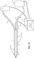
- FIG. 1A illustrates a device in a deflated condition having a body with two superimposed compartments 1, 2.
- Each compartment 1, 2 has a generally flat or convex surface area that may or may not be expandable.
- the device is connected to an electrical line 10 connected to a controller 11 for controlling the operation of energy sources or for filling or releasing the compartments 1, 2 with gas or liquid by ports 3, 4, among other things.
- Ports 3 or 4 may be complex electrical controllers that actuate a microwave, ultrasound, laser or other mechanism that is embedded within a compartment that causes heating or cooling.
- FIG. 1B illustrates the same device having an expanded ablation compartment 1 and an expanded anti-ablation compartment 2. The surface areas are convex in this shown embodiment.
- the controller 11 can supply power to electrical energy sources or fluid or gas sources that are provided to the compartments 1, 2 by ports 3 and 4, which are dedicated to the ablation compartment and to the anti-ablation compartment, respectively.
- the septum 5 is configured to have insulating properties.
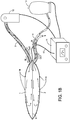
- the device is in the shape of a quadrilateral with smooth transitions in the corners, with the lower left corner being displaced away from the others, looking down upon ablation compartment 1.
- port 3 delivers and recycles gas or liquid in (or provides power to) chamber 1
- port 4 uniquely accesses anti-ablation compartment 2, which is positioned behind compartment 1.
- the shape of this device conforms to the general shape of the posterior wall of the left atrium, with margin 8 being superior (dome of the left atrium), margin 7 abutting the left-sided pulmonary veins posteriorly, margin 6 abutting the right sided pulmonary veins posteriorly, and margin 9 abutting the most inferior aspect of the posterior left atrium, near its junction with the anatomic structure known as the coronary sinus. It should be noted that the left lower corner is displaced away from the rest of the quadrilateral.
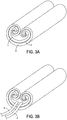
- FIGS. 3A-3C show the body of the device in a collapsed configuration, rolled up onto itself from both the left and right sides.
- the specific pattern of rolling allows for the anti-ablation compartment 2 to be on the bottom or external aspect of the rolled up device, while the ablation compartment 1 is on the internal aspect.
- FIG. 3B shows a more complete view of the device, with ports 3 and 4 connected to the rolled up device at its trailing end, e.g., by margin 9 shown to be deployed in FIG. 2 .
- FIG. 3C shows the device partially expanding or unfurling, with the anti-ablation compartment 2 being rolled out underneath of ablation compartment 1, which is being exposed by the device unfurling.
- the leading end of the device e.g., margin 8 is advanced underneath the heart (not shown), where once unfurled, the ablation compartment 1 comes into direct contact with the posterior wall of the left atrium.
- FIG. 4A in another example, not within the scope of the claims, a device with a stepwise elongation towards a left lower corner or pole (when viewed from above) is shown, with different-sized electrical coils to produce heat.
- FIG. 4B shows coupling of individual cells with a surface area shape that elongates moving from right to left, with the largest area being the left lower aspect; these cells may emit ultrasound, microwave, laser, or another energy source.
- FIG. 4C shows a device similar to the device shown in FIG. 4B when viewed from its right side, with an ablating surface compartment 1, and a separate and underlying component 2 to counteract ablation of compartment 1, actuated or controlled via ports dedicated to each compartment.
- the ablation compartment 1 is connected to a source 12 of nitrous oxide (or another gas/liquid) via port/line 3.
- the anti-ablation compartment 2 is connected to a source 13 of warm saline solution via port/line 4.
- the sources 12, 13 may be electrical energy sources.
- the controller 11 is configured to control the operation of the device in accordance to inputs provided by an operator of the device.
- the device disclosed herein may embody different configurations.
- the first compartment 1 is configured to resorb energy by cryothermy or freezing and the second compartment 2 is configured to emit energy or insulates against croythermy.
- the first compartment 1 is configured to emit energy by radiofrequency, ultrasound, microwave, magnetism or laser and the second compartment 2 is configured to utilize a cooling mechanism.
- At least one port 3 or 4 communicates with each of the two compartments individually. In another embodiment, at least one port 3 or 4 is used for shuttling gas or liquid.
- At least one of the compartments 1 or 2 has integrated temperature sensors, each indicated at 14, to measure or otherwise detect temperature in the compartment.
- both compartments 1, 2 have integrated temperature sensors.
- the sensors 14 are coupled to the controller, e.g., by line 10, to provide information to the controller 11. Based on the feedback from the sensors 14, the controller 11 and/or an operator of the controller can manipulate the flow of material/energy from sources 12, 13 via ports/lines 3, 4, respectively.
Description
- Ablation of living tissue has been used as a therapeutic intervention to cure or improve certain disease states. More specifically, ablation of cardiac tissue has been used to treat a variety of cardiac rhythm disturbances, including those originating in both the atria (upper chambers) and ventricles (lower chambers). Most of these techniques involve the utilization of an energy source (radiofrequency energy, cryothermy, microwave, ultrasound or laser) to destroy living tissue and render such tissue into a scar that is incapable of conducting electrical energy. Regarding atrial fibrillation specifically, most ablative strategies target the pulmonary vein orifices and their transitions to the left atrium, while others are meant to create linear scar lesions within and around the left and right atria themselves. In another technique, as disclosed in
US2003/0125721 A1 , balloon cryoablation of the pulmonary vein orifices, creates broad circular lesions by freezing the areas where a balloon is placed to occlude the pulmonary vein, ideally at its junction with the left atrium proper. All of these strategies aim to either encircle or "box-in" target areas, or focally interrupt areas considered to be important sources of atrial fibrillation (always with a major focus on the pulmonary veins). - More recently, the role of the posterior wall of the left atrium heart chamber has been recognized as significant in more "advanced" forms of atrial fibrillation, and its role in "sustaining" atrial fibrillation, possibly by becoming hyperconductive due to eccentric scar formation. It has been postulated that thorough ablation of both the pulmonary vein origins and the entire posterior wall of the left atrium would be a very effective strategy specifically for advanced forms of atrial fibrillation (including persistent cases), and methods to implement this strategy have been emerging, but the tools are somewhat limited. While pulmonary vein ablation strategies work well in patients with smaller left atrium heart chambers and those who have earlier stage atrial fibrillation (paroxysmal or intermittent), many patients have more persistent forms of atrial fibrillation that cannot be treated successfully with pulmonary vein ablation (or "isolation") alone. There have been attempts to ablate the posterior wall of the left atrium from "within" the left atrium, but in order to be effective, many lesions need to be delivered, each with a small but finite risk of other organ injury, including the airway and the esophagus. The document
US2007/0233226 discloses a device for ablation of epicardial tissue adjacent one or more pulmonary veins to treat atrial fibrillation. The device comprises a tissue attaching bladder for contacting the device with body tissue and a rigidifying bladder coupled with the tissue attaching bladder. - Older surgical strategies (cut-and-sew Maze procedure) have shown reproducible success in these advanced cases, but the surgeries can be risky (require use of the heart-lung machine and cardiac arrest). Attempts to reproduce the extensive surgical lesions using minimally invasive techniques or less invasive tools (compared with "cut and sew") showed some promise, but success rates have been modest and the "minimally invasive" nature has still been considered by most to be substantially invasive.
- Among atrial fibrillation experts, it has been widely agreed that anatomically, the pulmonary vein transitions are the source of most of the irregular voltage that typically initiates atrial fibrillation, but in advanced cases, the posterior aspect (back wall) of the left atrium somehow sustains the process of atrial fibrillation, even if the pulmonary veins have been ablated to be electrically isolated from the left atrium. Unfortunately, catheter-based strategies that aim to treat the posterior wall from the inside of the atrium are much more risky procedures than usual because of potential damage to contiguous structures, such as the esophagus, that lie right behind the left atrium that can be injured by inappropriate energy delivery. Further, the results with catheter treatment (called CFAE ablation: complex fractionated atrial electrograms) vary dramatically because the catheter treatment lesions (burns or freezes) are far too small (like point- or spot-welding) to effectively treat (ablate) large and contiguous areas of posterior left atrial tissue. More recently, a linear ablation device has been used that can ablate multiple small strips of the posterior left atrium from the outside (avoiding damage to contiguous organs like the airway and esophagus), but in a piece-meal fashion. The approach has demonstrated good proof of principle for treating persistent forms of atrial fibrillation with a limited experience. The method seems to be more effective than "within-the-left atrium" approaches (catheter ablation), but is tedious to use, as it was intended as a device that creates roughly 3 cm x 0.5 cm linear lesions to mimic aspects of the cut-and-sew Maze procedure, but is an imperfect device and method to treat the entire posterior left atrium as it comprises a much larger surface. Another important limitation is that radiofrequency energy algorithms typically self-limit energy delivery with increasing impedance (resistance) of the target tissue, such as occurs with the presence of epicardial fat, which sometimes insulates the posterior left atrial surface and may significantly inhibit ablation. Further, reaching certain parts of the posterior left atrium requires a level of technical proficiency that may be difficult to reproducibly achieve. Since atrial fibrillation is a serious disease that affects one in four Americans over 40 at some point in their lifetime, a treatment that is efficacious/reproducible, less invasive, quick, and easy to learn and apply has dramatic appeal and could save the healthcare system billions of dollars.
- The invention relates to an ablation device as defined in
claim 1. Preferred embodiments are defined in the dependent claims. Further aspects and examples, not within the scope of the claims, may also be disclosed. - One aspect of the disclosure is directed to a non-linear ablation device comprising two opposing surfaces. The opposing surfaces are associated with two overlying and separate compartments, with a first compartment of the two overlying and separate compartments being configured to emit or resorb energy, and a second compartment of the two overlying and separate compartments being configured to either resorb or emit energy to oppose a direction of energy transfer of the first compartment.
- Embodiments of the device may be configured so that the first compartment resorbs energy by cryothermy or freezing (e.g., shuttling and venting gas, such as nitrogen oxide (N2O) or Argon, or another suitable gas) and the second compartment emits energy or insulates against croythermy (for example, by either active warming with an energy source or by circulating and venting tepid or warm saline or other fluid) to prevent energy resorption below the first compartment, where energy resorption (ablation by freezing) would not be intended.
- The first compartment may emit energy by radiofrequency, ultrasound, microwave, magnetism or laser. The second compartment may then utilize a cooling mechanism, which could be accomplished with gas shuttling, such as N2O or Argon, or with continuous infusion of tepid or cool saline (or other) solution that is vented outside the chamber after circulation and absorption of excess energy.
- At least one port may communicate with each of the two compartments individually. The at least one port may be used for shuttling gas or liquid, or to power/control electrical components, such as radiofrequency, laser or ultrasound.
- The surface of at least one compartment may be generally shaped like a quadrilateral with one corner displaced further away from the other three corners (usually the lower left corner as shown and described herein) compared with how the other three corners are located with respect to one another.
- The compartments may be expandable from a smaller collapsed shape. The device may be collapsible or expandable by a roll-up mechanism; the device can be unrolled or expanded by infusing gas or liquid into the compartments or by another mechanical method. At least one of the compartments may have integrated temperature sensors. Surfaces of at least one of the compartments may be generally convex. Each surface may have a surface area of at least six cm2.
- Another aspect of the disclosure is directed to a method for ablating a broad and generally large planar area of tissue while heating or cooling a surface opposite an ablation target area to prevent ablation of an opposite surface.
- Examples of the method may be achieved by a non-linear ablation device having two opposing surfaces. The opposing surfaces may be associated with two overlying and separate compartments, with a first compartment of the two overlying and separate compartments being configured to emit or resorb energy, and a second compartment of the two overlying and separate compartments being configured to either resorb or emit energy to oppose a direction of energy transfer of the first compartment. Each surface may have a surface area of at least six cm2.The first compartment may resorb energy by cryothermy or freezing and the second compartment may emit energy or insulate against croythermy.
- Yet another aspect of the disclosure is directed to a non-linear ablation device comprising two opposing surfaces. Each surface has a surface area of at least six cm2. The opposing surfaces are associated with two overlying and separate compartments, with a first compartment of the two overlying and separate compartments being configured to emit or resorb energy, and a second compartment of the two overlying and separate compartments being configured to either resorb or emit energy to oppose a direction of energy transfer of the first compartment. The non-linear ablation device is expandable from a smaller initial, collapsed configuration.
- Another aspect of the disclosure is directed to a non-linear ablation device comprising two opposing surfaces. Each surface has a surface area of at least six cm2. The opposing surfaces are associated with two overlying and separate compartments, with a first compartment of the two overlying and separate compartments being configured to resorb energy by cryothermy or freezing, and a second compartment of the two underlying and separate compartment being configured to emit energy to oppose the cryothermy of the first compartment.
- A further aspect of the disclosure is directed to a non-linear ablation device comprising two opposing surfaces. Each surface has a surface area of at least six cm2. The opposing surfaces are associated with two overlying and separate compartments, with a first compartment of the overlying and separate compartments being configured to emit or resorb energy, and a second compartment of the two underlying and separate compartment being configured to either resorb or emit energy to oppose a direction of energy transfer of the first compartment. The surface of the device is shaped like a quadrilateral with one corner displaced/elongated further away from the other three corners compared with the other three corners, which are located with respect to one another. The displace/elongated corner may be the left lower corner, as shown and described herein.
- Another aspect of the disclosure is directed to a device having a surface area with a drooping/elongated lower left corner, the surface area may comprise a more stepwise elongation towards the left lower corner of the device as shown and described herein. This arrangement enables more rigid sub-components to be incorporated into the ablation compartment of the device, such as microwave or ultrasound cells or radiofrequency/energy coils of differing lengths.
- A further aspect of the disclosure is directed to a non-linear ablation device comprising two opposing surfaces, each surface having a surface area of at least six cm2. The opposing surfaces are associated with two overlying and separate compartments, with a first compartment of the two overlying and separate compartments being configured to resorb energy by cryothermy or freezing, and a second compartment of the two underlying and separate compartments being configured to emit energy to oppose the cryothermy of the first compartment. The non-linear device is expandable from a smaller initial, collapsed configuration. The surface of at least one compartment is generally shaped like a quadrilateral with one corner displaced further away from the other three corners.
- The device described overcomes technical limitations of current approaches of posterior left atrium surface ablation by ablating a large and appropriate sized area of the posterior left atrium that can overcome limitations of radiofrequency energy ablation, while protecting adjacent (unintended) areas from ablation injury by providing a size-matched simultaneous counter-action to the ablative energy source. An important iteration is a device that is deployed from a smaller size, so as to be used for a minimally invasive procedure. Other aspects of the disclosure that facilitate easier implementation are surface shapes that generally match those of the posterior left atrium, which has an eccentric shape that is like a rectangle with a drooping/extending left lower corner.
- The accompanying drawings are not intended to be drawn to scale. In the drawings, each identical or nearly identical component that is illustrated in various figures is represented by a like numeral. For purposes of clarity, not every component may be labeled in every drawing. In the drawings:
-
FIG. 1A shows a device in an deflated condition from its right side, the device including an upper ablation chamber that is superimposed over a lower (anti-ablation) chamber that may or may not be expandable; -
FIG. 1B shows the device in an inflated condition; -
FIG. 2 shows a top view of a device shaped like a posterior left atrium, with a quadrilateral having smooth transitions in the corners, and a lower left corner being displaced away from the others; -
FIGS. 3A-3C show a collapsed device that is rolled up from the left and right sides, transitioning to an opened configuration of the device; and -
FIG. 4A-4C show a device with a stepwise increase in surface area moving from right to left, with increases occurring towards the left lower corner or pole of the device when viewed in plan, with the device iterations utilizing microwave or ultrasound cells or differing length radiofrequency coils. - A device for simultaneous ablation of a relatively large surface area of tissue whose shape can be in contact with much or all of the available surface area of the posterior (back) wall of the left atrium is disclosed herein. The device can be polar, having a front surface and a back surface, with only one surface intended to be in contact with the posterior left atrium, and the other surface being opposite the posterior left atrium. Generally, the device shape can be non-linear, and the front surface and the back surface can be flat or convex and exceed six cm2 in surface area. The shape of the posterior left atrium can be complex and eccentric, but generally can be considered to be similar to a quadrilateral with non-parallel sides and rounded edges, with a tapering and increasing inferior aspect moving from right to left.
- In one example, a device that can thoroughly ablate the entire left atrium in ideally one ablation, or, for example, in less than four ablations, is shown and described. In addition, the device can be ideally deployed using established minimally invasive approaches to the posterior left atrium, and in these cases would be expandable from a smaller collapsed initial configuration. An energy source ideally can be one that overcomes epicardial fat-insulation limitations of radiofrequency ablation algorithms so that all of the posterior left atrium can be successfully and quickly ablated with minimal risk. Adjunctive procedures, such as cryoballoon ablation of the pulmonary veins, are added to complete the ablation procedure.
- In a major iteration, the device is expandable from a collapsed configuration into a relatively flat or convex bladder (compartment) or overlying set of bladders (compartments) that is/are delivered into the posterior pericardium (beneath the posterior left atrium) using video surgery or through a direct approach below the heart, and ablating a broad surface area of the posterior left atrium while protecting against underlying adjacent organ injury. While the energy source described herein is cryothermy, it is conceivable that alternate energy sources could be used as well, such as radiofrequency, microwave, magnetism, ultrasound or laser. An important feature of the device is counteraction of the posterior left atrial cooling or heating either by insulation or with broad-area provision of opposing warming or cooling action in an opposing bladder (compartment) to protect adjacent tissues opposite to the posterior (back) wall of the left atrium. The ablation surface or chamber may separate from an anti-ablation chamber by a septum, or, there may be two independent but superimposed chambers or bladders.
- In one example, the device is delivered into position as a collapsed item that is expandable or inflatable by being filled with gas or liquid or by any other mechanism. When expanded, the device can achieve a square, rectangular, oval, circular, and trapezoidal or another shape. A preferred iteration is a single device that is designed in the general shape of the posterior surface of the human left atrium, having a generally quadrilateral or rectangular shaped device with four corners or poles, and with one corner that is elongated and/or widened, with the surface area of the device generally being over six cm2 in area. In one embodiment, the device is shaped like a quadrilateral with the left lower corner displaced further away from the other three corners compared with how the other three corners are located with respect to one another. The ablation surface or chamber, which will ultimately be placed in contact with the back wall of the left atrium, is activated, loaded or charged with an ablation capacity, as by freezing or heating, and the anti-ablation chamber (on the polar opposite side of the ablation chamber/surface, and generally of similar dimensions) is loaded or charged with a warming or cooling capacity or some other method of protecting structures adjacent from the posterior left atrium from injury.
- The device may include two plastic (e.g., polyurethane) compartments or bladders, the ablation chamber being infused with a liquid or gas, such as nitric or nitrous oxide, argon or helium, to achieve sub-zero temperatures, while the anti-ablation chamber is infused with warmed gas or liquid solution, or by any means to emit heat or energy. The anti-ablation portion can be a protective or insulating barrier and not require shuttling of gas or liquid. One or both chambers may contain integrated thermometers to monitor dynamic and steady-state temperatures during the ablation process in order to achieve and maintain specified targets for completeness of ablation as well as protection from injury. The device could generally work like a double-sided bladder that is placed behind the left atrium heart chamber. One side of the bladder may be positioned in direct contact with the posterior (back) wall of the left atrium, while the other side of the device/bladder may be in contact with the posterior pericardial sac, but not with the left atrium or heart itself. The anti-ablation part of the device protects structures on the other side of the pericardial sac in that area (esophagus, aorta, lung, airway, nerves, and diaphragm, for example). After the ablation sequence is completed, an expandable device can then again be partially or completely collapsed again for retrieval.
- Referring to the drawings,
FIG. 1A illustrates a device in a deflated condition having a body with twosuperimposed compartments compartment electrical line 10 connected to acontroller 11 for controlling the operation of energy sources or for filling or releasing thecompartments ports Ports FIG. 1B illustrates the same device having an expandedablation compartment 1 and an expandedanti-ablation compartment 2. The surface areas are convex in this shown embodiment. Thecontroller 11 can supply power to electrical energy sources or fluid or gas sources that are provided to thecompartments ports septum 5 that separatesablation compartment 1 fromanti-ablation compartment 2. Theseptum 5 is configured to have insulating properties. - Referring to
FIG. 2 , the device is in the shape of a quadrilateral with smooth transitions in the corners, with the lower left corner being displaced away from the others, looking down uponablation compartment 1. As shown,port 3 delivers and recycles gas or liquid in (or provides power to)chamber 1, whileport 4 uniquely accessesanti-ablation compartment 2, which is positioned behindcompartment 1. The shape of this device conforms to the general shape of the posterior wall of the left atrium, withmargin 8 being superior (dome of the left atrium),margin 7 abutting the left-sided pulmonary veins posteriorly,margin 6 abutting the right sided pulmonary veins posteriorly, andmargin 9 abutting the most inferior aspect of the posterior left atrium, near its junction with the anatomic structure known as the coronary sinus. It should be noted that the left lower corner is displaced away from the rest of the quadrilateral. - Referring to
FIGS. 3A-3C ,FIGS. 3A and 3B show the body of the device in a collapsed configuration, rolled up onto itself from both the left and right sides. In this example, the specific pattern of rolling allows for theanti-ablation compartment 2 to be on the bottom or external aspect of the rolled up device, while theablation compartment 1 is on the internal aspect.FIG. 3B shows a more complete view of the device, withports margin 9 shown to be deployed inFIG. 2 .FIG. 3C shows the device partially expanding or unfurling, with theanti-ablation compartment 2 being rolled out underneath ofablation compartment 1, which is being exposed by the device unfurling. The leading end of the device, e.g.,margin 8, is advanced underneath the heart (not shown), where once unfurled, theablation compartment 1 comes into direct contact with the posterior wall of the left atrium. - Referring to
FIG. 4A , in another example, not within the scope of the claims, a device with a stepwise elongation towards a left lower corner or pole (when viewed from above) is shown, with different-sized electrical coils to produce heat. SimilarlyFIG. 4B shows coupling of individual cells with a surface area shape that elongates moving from right to left, with the largest area being the left lower aspect; these cells may emit ultrasound, microwave, laser, or another energy source.FIG. 4C shows a device similar to the device shown inFIG. 4B when viewed from its right side, with anablating surface compartment 1, and a separate andunderlying component 2 to counteract ablation ofcompartment 1, actuated or controlled via ports dedicated to each compartment. - Referring back to
FIGS. 1A and1B , in one embodiment, theablation compartment 1 is connected to asource 12 of nitrous oxide (or another gas/liquid) via port/line 3. Theanti-ablation compartment 2 is connected to asource 13 of warm saline solution via port/line 4. In other examples, not within the scope of the claims, thesources controller 11 is configured to control the operation of the device in accordance to inputs provided by an operator of the device. - The device disclosed herein may embody different configurations. According to the invention, the
first compartment 1 is configured to resorb energy by cryothermy or freezing and thesecond compartment 2 is configured to emit energy or insulates against croythermy. - In another example, not within the scope of the claims, the
first compartment 1 is configured to emit energy by radiofrequency, ultrasound, microwave, magnetism or laser and thesecond compartment 2 is configured to utilize a cooling mechanism. - In certain embodiments, at least one
port port - In one embodiment, with reference to
FIGS. 1A and1B , at least one of thecompartments compartments sensors 14 are coupled to the controller, e.g., byline 10, to provide information to thecontroller 11. Based on the feedback from thesensors 14, thecontroller 11 and/or an operator of the controller can manipulate the flow of material/energy fromsources lines - This disclosure is not limited in its application to the details of construction and the arrangement of components set forth in the following description or illustrated in the drawings. The principles set forth in this disclosure are capable of being provided in other embodiments and of being practiced or of being carried out in various ways. Also, the phraseology and terminology used herein is for the purpose of description and should not be regarded as limiting. The use of "including," "comprising," "having," "containing," "involving," and variations thereof herein, is meant to encompass the items listed thereafter and equivalents thereof as well as additional items.
- Having thus described several aspects of at least one embodiment of this disclosure, it is to be appreciated various alterations, modifications, and improvements will readily occur to those skilled in the art. Such alterations, modifications, and improvements are intended to be part of this disclosure, and are intended to be within the scope of the disclosure. Accordingly, the foregoing description and drawings are by way of example only.
Claims (8)
- An ablation device for ablating a posterior wall of a left atrium of a patient's heart, the device comprising a device body comprising:(a) an energy resorption compartment (1) comprising a resorption surface having a general shape of the posterior wall of the left atrium of the patient's heart;(b) an insulation compartment (2) disposed adjacent to the energy resorption compartment (1), the insulation compartment (2) comprising an insulation surface;(c) a line (3) coupled to a first side of the device body, the line comprising:wherein the insulation surface is disposed on an opposite side of the ablation device in relation to the resorption surface,(i) a fluid delivery channel in fluidic communication with the energy resorption compartment (1); and(ii) a fluid removal channel in fluidic communication with the energy resorption compartment (1), wherein the fluid delivery channel is constructed and arranged to deliver a cryothermy ablation fluid and the fluid removal channel is constructed and arranged to remove the cryothermy ablation fluid such that the cryothermy ablation fluid is shuttled through the energy resorption compartment (1),
wherein the insulation compartment (2) is configured to insulate surrounding tissues from the energy resorption compartment (1),
wherein each of the resorption surface and the insulation surface has a surface area of at least six cm2;
wherein the device body has a collapsed configuration wherein the device body comprises a collapsed size and shape such that the device body can be deployed via a minimally invasive procedure, and
wherein the device body has an expanded configuration wherein the resorption surface is a relatively flat shape and is sized and shaped in the expanded configuration to contact a large planar area of the posterior wall of the left atrium of the patient's heart. - The device of claim 1, wherein the insulation compartment (2) emits energy.
- The device of claim 1, wherein the cryothermy ablation fluid comprises gas.
- The device of claim 1, 2 or 3, wherein the resorption surface is generally shaped like a quadrilateral with one corner displaced further away from the other three corners compared with how the other three corners are located with respect to one another.
- The device of claim 1, wherein the device is collapsible into the collapsed configuration and expandable into the expanded configuration by a roll-up mechanism.
- The device of claim 1, wherein at least one of the compartments has integrated temperature sensors (14).
- The device of claim 1, wherein the expanded configuration comprises the insulation surface being substantially convex.
- The device of claim 1, wherein the cryothermy ablation fluid is helium.
Applications Claiming Priority (2)
| Application Number | Priority Date | Filing Date | Title |
|---|---|---|---|
| US201361909218P | 2013-11-26 | 2013-11-26 | |
| PCT/US2014/067143 WO2015081019A2 (en) | 2013-11-26 | 2014-11-24 | Action/counteraction superimposed double chamber, broad area tissue ablation device |
Publications (3)
| Publication Number | Publication Date |
|---|---|
| EP3073931A2 EP3073931A2 (en) | 2016-10-05 |
| EP3073931A4 EP3073931A4 (en) | 2017-10-11 |
| EP3073931B1 true EP3073931B1 (en) | 2020-05-13 |
Family
ID=53199717
Family Applications (1)
| Application Number | Title | Priority Date | Filing Date |
|---|---|---|---|
| EP14865507.9A Active EP3073931B1 (en) | 2013-11-26 | 2014-11-24 | Action/counteraction superimposed double chamber, broad area tissue ablation device |
Country Status (10)
| Country | Link |
|---|---|
| US (2) | US10166058B2 (en) |
| EP (1) | EP3073931B1 (en) |
| JP (2) | JP6154073B2 (en) |
| KR (1) | KR101827290B1 (en) |
| CN (1) | CN105813576B (en) |
| AU (1) | AU2014354940B2 (en) |
| CA (1) | CA2931484C (en) |
| ES (1) | ES2793936T3 (en) |
| IL (2) | IL245779B (en) |
| WO (1) | WO2015081019A2 (en) |
Families Citing this family (4)
| Publication number | Priority date | Publication date | Assignee | Title |
|---|---|---|---|---|
| CN106580425B (en) * | 2016-11-28 | 2019-08-02 | 攀枝花市九鼎智远知识产权运营有限公司 | A kind of liquid nitrogen frozen knife with hot warm cutting function |
| US11771486B2 (en) | 2017-01-17 | 2023-10-03 | Corfigo, Inc. | Device for ablation of tissue surfaces and related systems and methods |
| US20190159835A1 (en) * | 2017-11-29 | 2019-05-30 | Atricure, Inc. | Cryopad |
| US11690663B1 (en) * | 2022-11-03 | 2023-07-04 | Focused Cryo, Inc. | Directional cryoablation system |
Family Cites Families (20)
| Publication number | Priority date | Publication date | Assignee | Title |
|---|---|---|---|---|
| NL1001890C2 (en) | 1995-12-13 | 1997-06-17 | Cordis Europ | Catheter with plate-shaped electrode array. |
| WO1999047085A1 (en) * | 1998-03-17 | 1999-09-23 | Kochamba Gary S | Method and apparatus for stabilizing tissue |
| US7001378B2 (en) * | 1998-03-31 | 2006-02-21 | Innercool Therapies, Inc. | Method and device for performing cooling or cryo-therapies, for, e.g., angioplasty with reduced restenosis or pulmonary vein cell necrosis to inhibit atrial fibrillation employing tissue protection |
| US7097641B1 (en) | 1999-12-09 | 2006-08-29 | Cryocath Technologies Inc. | Catheter with cryogenic and heating ablation |
| US6932771B2 (en) * | 2001-07-09 | 2005-08-23 | Civco Medical Instruments Co., Inc. | Tissue warming device and method |
| US20030153905A1 (en) * | 2002-01-25 | 2003-08-14 | Edwards Stuart Denzil | Selective ablation system |
| WO2004004545A2 (en) | 2002-07-03 | 2004-01-15 | Expanding Concepts, L.L.C. | Ribbon epidural thermal posterior annuloplasty |
| US6858025B2 (en) * | 2002-08-06 | 2005-02-22 | Medically Advanced Designs, Llc | Cryo-surgical apparatus and method of use |
| US7179254B2 (en) * | 2004-03-09 | 2007-02-20 | Ethicon, Inc. | High intensity ablation device |
| US9555223B2 (en) * | 2004-03-23 | 2017-01-31 | Medtronic Cryocath Lp | Method and apparatus for inflating and deflating balloon catheters |
| US7803150B2 (en) * | 2004-04-21 | 2010-09-28 | Acclarent, Inc. | Devices, systems and methods useable for treating sinusitis |
| WO2007069258A2 (en) * | 2005-12-15 | 2007-06-21 | Galil Medical Ltd. | Apparatus for protecting a cavity wall during ablation of tissue near the cavity |
| US20070287994A1 (en) * | 2006-06-12 | 2007-12-13 | Pankaj Amrit Patel | Endoscopically Introducible Expandable Bipolar Probe |
| US20080077126A1 (en) | 2006-09-22 | 2008-03-27 | Rassoll Rashidi | Ablation for atrial fibrillation |
| CA2703414A1 (en) * | 2008-01-11 | 2009-07-16 | Boston Scientific Scimed, Inc. | Ablation devices and methods of use |
| US9603674B2 (en) * | 2008-05-30 | 2017-03-28 | The Regents Of The University Of California | Method to protect the esophagus and other mediastinal structures during cardiac and thoracic interventions |
| US8097926B2 (en) * | 2008-10-07 | 2012-01-17 | Mc10, Inc. | Systems, methods, and devices having stretchable integrated circuitry for sensing and delivering therapy |
| US8956346B2 (en) * | 2010-05-14 | 2015-02-17 | Rainbow Medical, Ltd. | Reflectance-facilitated ultrasound treatment and monitoring |
| US8790300B2 (en) * | 2010-12-06 | 2014-07-29 | Boston Scientific Scimed, Inc. | Dual balloon catheter |
| JP2013132364A (en) | 2011-12-26 | 2013-07-08 | Nippon Erekuteru:Kk | Balloon catheter |
-
2014
- 2014-11-24 AU AU2014354940A patent/AU2014354940B2/en active Active
- 2014-11-24 US US14/772,654 patent/US10166058B2/en active Active
- 2014-11-24 CA CA2931484A patent/CA2931484C/en active Active
- 2014-11-24 CN CN201480064585.1A patent/CN105813576B/en active Active
- 2014-11-24 EP EP14865507.9A patent/EP3073931B1/en active Active
- 2014-11-24 KR KR1020167017124A patent/KR101827290B1/en active IP Right Grant
- 2014-11-24 WO PCT/US2014/067143 patent/WO2015081019A2/en active Application Filing
- 2014-11-24 ES ES14865507T patent/ES2793936T3/en active Active
- 2014-11-24 JP JP2016535007A patent/JP6154073B2/en active Active
-
2016
- 2016-05-23 IL IL245779A patent/IL245779B/en active IP Right Grant
-
2017
- 2017-06-01 JP JP2017109020A patent/JP6526106B2/en active Active
-
2018
- 2018-10-10 IL IL262253A patent/IL262253B/en active IP Right Grant
- 2018-12-31 US US16/236,875 patent/US20190133667A1/en not_active Abandoned
Non-Patent Citations (1)
| Title |
|---|
| None * |
Also Published As
| Publication number | Publication date |
|---|---|
| AU2014354940B2 (en) | 2016-12-22 |
| EP3073931A2 (en) | 2016-10-05 |
| JP6154073B2 (en) | 2017-06-28 |
| KR20160091971A (en) | 2016-08-03 |
| EP3073931A4 (en) | 2017-10-11 |
| CA2931484A1 (en) | 2015-06-04 |
| CN105813576B (en) | 2019-11-12 |
| US20190133667A1 (en) | 2019-05-09 |
| KR101827290B1 (en) | 2018-03-22 |
| IL245779A0 (en) | 2016-07-31 |
| AU2014354940A1 (en) | 2016-06-09 |
| JP2017192740A (en) | 2017-10-26 |
| CA2931484C (en) | 2019-10-29 |
| IL262253A (en) | 2018-11-29 |
| CN105813576A (en) | 2016-07-27 |
| IL262253B (en) | 2020-07-30 |
| ES2793936T3 (en) | 2020-11-17 |
| JP2017500928A (en) | 2017-01-12 |
| JP6526106B2 (en) | 2019-06-05 |
| WO2015081019A3 (en) | 2015-10-22 |
| US20160338752A1 (en) | 2016-11-24 |
| IL245779B (en) | 2018-10-31 |
| US10166058B2 (en) | 2019-01-01 |
| WO2015081019A2 (en) | 2015-06-04 |
Similar Documents
| Publication | Publication Date | Title |
|---|---|---|
| US20190133667A1 (en) | Action/Counteraction Superimposed Double Chamber Board Area Tissue Ablation Device | |
| US8579889B2 (en) | Linear ablation devices and methods of use | |
| US7871409B2 (en) | Endocardial dispersive electrode for use with a monopolar RF ablation pen | |
| US9636172B2 (en) | Compliant balloon with liquid injection | |
| US9603674B2 (en) | Method to protect the esophagus and other mediastinal structures during cardiac and thoracic interventions | |
| US20190223948A1 (en) | Energy delivery return path devices and methods | |
| US20120316488A1 (en) | Method and Devices for Treating Atrial Fibrillation by Mass Ablation | |
| WO2013013098A1 (en) | System and method for creation of cox maze lesions | |
| US20220133400A1 (en) | Ablation devices and methods of use | |
| JP6570813B2 (en) | Adaptive electrodes for bipolar ablation | |
| KR20220014275A (en) | Controlling irreversible electroporation ablation using a focal catheter having contact-force and temperature sensors | |
| KR20220008205A (en) | Sequential activation of electrode-pairs during irreversible electroporation (ire) | |
| US20190159835A1 (en) | Cryopad | |
| Biase et al. | Catheter cryoablation for the treatment of ventricular arrhythmias | |
| WO2020104462A1 (en) | Ablation catheter and ablation device comprising such an ablation catheter |
Legal Events
| Date | Code | Title | Description |
|---|---|---|---|
| PUAI | Public reference made under article 153(3) epc to a published international application that has entered the european phase |
Free format text: ORIGINAL CODE: 0009012 |
|
| 17P | Request for examination filed |
Effective date: 20160523 |
|
| AK | Designated contracting states |
Kind code of ref document: A2 Designated state(s): AL AT BE BG CH CY CZ DE DK EE ES FI FR GB GR HR HU IE IS IT LI LT LU LV MC MK MT NL NO PL PT RO RS SE SI SK SM TR |
|
| AX | Request for extension of the european patent |
Extension state: BA ME |
|
| DAX | Request for extension of the european patent (deleted) | ||
| RIN1 | Information on inventor provided before grant (corrected) |
Inventor name: SPERLING, JASON SCOTT |
|
| A4 | Supplementary search report drawn up and despatched |
Effective date: 20170907 |
|
| RIC1 | Information provided on ipc code assigned before grant |
Ipc: A61B 8/14 20060101AFI20170901BHEP |
|
| RAP1 | Party data changed (applicant data changed or rights of an application transferred) |
Owner name: CORFIGO, INC. |
|
| STAA | Information on the status of an ep patent application or granted ep patent |
Free format text: STATUS: EXAMINATION IS IN PROGRESS |
|
| 17Q | First examination report despatched |
Effective date: 20180921 |
|
| RIN1 | Information on inventor provided before grant (corrected) |
Inventor name: SPERLING, JASON SCOTT |
|
| GRAP | Despatch of communication of intention to grant a patent |
Free format text: ORIGINAL CODE: EPIDOSNIGR1 |
|
| STAA | Information on the status of an ep patent application or granted ep patent |
Free format text: STATUS: GRANT OF PATENT IS INTENDED |
|
| INTG | Intention to grant announced |
Effective date: 20191202 |
|
| GRAS | Grant fee paid |
Free format text: ORIGINAL CODE: EPIDOSNIGR3 |
|
| GRAL | Information related to payment of fee for publishing/printing deleted |
Free format text: ORIGINAL CODE: EPIDOSDIGR3 |
|
| GRAS | Grant fee paid |
Free format text: ORIGINAL CODE: EPIDOSNIGR3 |
|
| GRAA | (expected) grant |
Free format text: ORIGINAL CODE: 0009210 |
|
| STAA | Information on the status of an ep patent application or granted ep patent |
Free format text: STATUS: THE PATENT HAS BEEN GRANTED |
|
| AK | Designated contracting states |
Kind code of ref document: B1 Designated state(s): AL AT BE BG CH CY CZ DE DK EE ES FI FR GB GR HR HU IE IS IT LI LT LU LV MC MK MT NL NO PL PT RO RS SE SI SK SM TR |
|
| REG | Reference to a national code |
Ref country code: GB Ref legal event code: FG4D |
|
| REG | Reference to a national code |
Ref country code: CH Ref legal event code: EP |
|
| REG | Reference to a national code |
Ref country code: DE Ref legal event code: R096 Ref document number: 602014065535 Country of ref document: DE |
|
| REG | Reference to a national code |
Ref country code: AT Ref legal event code: REF Ref document number: 1269170 Country of ref document: AT Kind code of ref document: T Effective date: 20200615 |
|
| REG | Reference to a national code |
Ref country code: NL Ref legal event code: FP |
|
| REG | Reference to a national code |
Ref country code: SE Ref legal event code: TRGR |
|
| REG | Reference to a national code |
Ref country code: LT Ref legal event code: MG4D |
|
| REG | Reference to a national code |
Ref country code: DE Ref legal event code: R082 Ref document number: 602014065535 Country of ref document: DE Representative=s name: VENNER SHIPLEY GERMANY LLP, DE Ref country code: DE Ref legal event code: R082 Ref document number: 602014065535 Country of ref document: DE Representative=s name: VENNER SHIPLEY LLP, DE |
|
| PG25 | Lapsed in a contracting state [announced via postgrant information from national office to epo] |
Ref country code: GR Free format text: LAPSE BECAUSE OF FAILURE TO SUBMIT A TRANSLATION OF THE DESCRIPTION OR TO PAY THE FEE WITHIN THE PRESCRIBED TIME-LIMIT Effective date: 20200814 Ref country code: FI Free format text: LAPSE BECAUSE OF FAILURE TO SUBMIT A TRANSLATION OF THE DESCRIPTION OR TO PAY THE FEE WITHIN THE PRESCRIBED TIME-LIMIT Effective date: 20200513 Ref country code: NO Free format text: LAPSE BECAUSE OF FAILURE TO SUBMIT A TRANSLATION OF THE DESCRIPTION OR TO PAY THE FEE WITHIN THE PRESCRIBED TIME-LIMIT Effective date: 20200813 Ref country code: LT Free format text: LAPSE BECAUSE OF FAILURE TO SUBMIT A TRANSLATION OF THE DESCRIPTION OR TO PAY THE FEE WITHIN THE PRESCRIBED TIME-LIMIT Effective date: 20200513 Ref country code: IS Free format text: LAPSE BECAUSE OF FAILURE TO SUBMIT A TRANSLATION OF THE DESCRIPTION OR TO PAY THE FEE WITHIN THE PRESCRIBED TIME-LIMIT Effective date: 20200913 Ref country code: PT Free format text: LAPSE BECAUSE OF FAILURE TO SUBMIT A TRANSLATION OF THE DESCRIPTION OR TO PAY THE FEE WITHIN THE PRESCRIBED TIME-LIMIT Effective date: 20200914 |
|
| REG | Reference to a national code |
Ref country code: ES Ref legal event code: FG2A Ref document number: 2793936 Country of ref document: ES Kind code of ref document: T3 Effective date: 20201117 |
|
| PG25 | Lapsed in a contracting state [announced via postgrant information from national office to epo] |
Ref country code: RS Free format text: LAPSE BECAUSE OF FAILURE TO SUBMIT A TRANSLATION OF THE DESCRIPTION OR TO PAY THE FEE WITHIN THE PRESCRIBED TIME-LIMIT Effective date: 20200513 Ref country code: LV Free format text: LAPSE BECAUSE OF FAILURE TO SUBMIT A TRANSLATION OF THE DESCRIPTION OR TO PAY THE FEE WITHIN THE PRESCRIBED TIME-LIMIT Effective date: 20200513 Ref country code: HR Free format text: LAPSE BECAUSE OF FAILURE TO SUBMIT A TRANSLATION OF THE DESCRIPTION OR TO PAY THE FEE WITHIN THE PRESCRIBED TIME-LIMIT Effective date: 20200513 Ref country code: BG Free format text: LAPSE BECAUSE OF FAILURE TO SUBMIT A TRANSLATION OF THE DESCRIPTION OR TO PAY THE FEE WITHIN THE PRESCRIBED TIME-LIMIT Effective date: 20200813 |
|
| REG | Reference to a national code |
Ref country code: AT Ref legal event code: MK05 Ref document number: 1269170 Country of ref document: AT Kind code of ref document: T Effective date: 20200513 |
|
| PG25 | Lapsed in a contracting state [announced via postgrant information from national office to epo] |
Ref country code: AL Free format text: LAPSE BECAUSE OF FAILURE TO SUBMIT A TRANSLATION OF THE DESCRIPTION OR TO PAY THE FEE WITHIN THE PRESCRIBED TIME-LIMIT Effective date: 20200513 |
|
| PG25 | Lapsed in a contracting state [announced via postgrant information from national office to epo] |
Ref country code: CZ Free format text: LAPSE BECAUSE OF FAILURE TO SUBMIT A TRANSLATION OF THE DESCRIPTION OR TO PAY THE FEE WITHIN THE PRESCRIBED TIME-LIMIT Effective date: 20200513 Ref country code: AT Free format text: LAPSE BECAUSE OF FAILURE TO SUBMIT A TRANSLATION OF THE DESCRIPTION OR TO PAY THE FEE WITHIN THE PRESCRIBED TIME-LIMIT Effective date: 20200513 Ref country code: DK Free format text: LAPSE BECAUSE OF FAILURE TO SUBMIT A TRANSLATION OF THE DESCRIPTION OR TO PAY THE FEE WITHIN THE PRESCRIBED TIME-LIMIT Effective date: 20200513 Ref country code: RO Free format text: LAPSE BECAUSE OF FAILURE TO SUBMIT A TRANSLATION OF THE DESCRIPTION OR TO PAY THE FEE WITHIN THE PRESCRIBED TIME-LIMIT Effective date: 20200513 Ref country code: SM Free format text: LAPSE BECAUSE OF FAILURE TO SUBMIT A TRANSLATION OF THE DESCRIPTION OR TO PAY THE FEE WITHIN THE PRESCRIBED TIME-LIMIT Effective date: 20200513 Ref country code: EE Free format text: LAPSE BECAUSE OF FAILURE TO SUBMIT A TRANSLATION OF THE DESCRIPTION OR TO PAY THE FEE WITHIN THE PRESCRIBED TIME-LIMIT Effective date: 20200513 |
|
| REG | Reference to a national code |
Ref country code: DE Ref legal event code: R097 Ref document number: 602014065535 Country of ref document: DE |
|
| PG25 | Lapsed in a contracting state [announced via postgrant information from national office to epo] |
Ref country code: PL Free format text: LAPSE BECAUSE OF FAILURE TO SUBMIT A TRANSLATION OF THE DESCRIPTION OR TO PAY THE FEE WITHIN THE PRESCRIBED TIME-LIMIT Effective date: 20200513 Ref country code: SK Free format text: LAPSE BECAUSE OF FAILURE TO SUBMIT A TRANSLATION OF THE DESCRIPTION OR TO PAY THE FEE WITHIN THE PRESCRIBED TIME-LIMIT Effective date: 20200513 |
|
| PLBE | No opposition filed within time limit |
Free format text: ORIGINAL CODE: 0009261 |
|
| STAA | Information on the status of an ep patent application or granted ep patent |
Free format text: STATUS: NO OPPOSITION FILED WITHIN TIME LIMIT |
|
| 26N | No opposition filed |
Effective date: 20210216 |
|
| PG25 | Lapsed in a contracting state [announced via postgrant information from national office to epo] |
Ref country code: SI Free format text: LAPSE BECAUSE OF FAILURE TO SUBMIT A TRANSLATION OF THE DESCRIPTION OR TO PAY THE FEE WITHIN THE PRESCRIBED TIME-LIMIT Effective date: 20200513 |
|
| PG25 | Lapsed in a contracting state [announced via postgrant information from national office to epo] |
Ref country code: MC Free format text: LAPSE BECAUSE OF FAILURE TO SUBMIT A TRANSLATION OF THE DESCRIPTION OR TO PAY THE FEE WITHIN THE PRESCRIBED TIME-LIMIT Effective date: 20200513 |
|
| REG | Reference to a national code |
Ref country code: CH Ref legal event code: PL |
|
| PG25 | Lapsed in a contracting state [announced via postgrant information from national office to epo] |
Ref country code: LU Free format text: LAPSE BECAUSE OF NON-PAYMENT OF DUE FEES Effective date: 20201124 |
|
| REG | Reference to a national code |
Ref country code: BE Ref legal event code: MM Effective date: 20201130 |
|
| PG25 | Lapsed in a contracting state [announced via postgrant information from national office to epo] |
Ref country code: LI Free format text: LAPSE BECAUSE OF NON-PAYMENT OF DUE FEES Effective date: 20201130 Ref country code: CH Free format text: LAPSE BECAUSE OF NON-PAYMENT OF DUE FEES Effective date: 20201130 |
|
| PG25 | Lapsed in a contracting state [announced via postgrant information from national office to epo] |
Ref country code: TR Free format text: LAPSE BECAUSE OF FAILURE TO SUBMIT A TRANSLATION OF THE DESCRIPTION OR TO PAY THE FEE WITHIN THE PRESCRIBED TIME-LIMIT Effective date: 20200513 Ref country code: MT Free format text: LAPSE BECAUSE OF FAILURE TO SUBMIT A TRANSLATION OF THE DESCRIPTION OR TO PAY THE FEE WITHIN THE PRESCRIBED TIME-LIMIT Effective date: 20200513 Ref country code: CY Free format text: LAPSE BECAUSE OF FAILURE TO SUBMIT A TRANSLATION OF THE DESCRIPTION OR TO PAY THE FEE WITHIN THE PRESCRIBED TIME-LIMIT Effective date: 20200513 |
|
| PG25 | Lapsed in a contracting state [announced via postgrant information from national office to epo] |
Ref country code: MK Free format text: LAPSE BECAUSE OF FAILURE TO SUBMIT A TRANSLATION OF THE DESCRIPTION OR TO PAY THE FEE WITHIN THE PRESCRIBED TIME-LIMIT Effective date: 20200513 |
|
| PG25 | Lapsed in a contracting state [announced via postgrant information from national office to epo] |
Ref country code: BE Free format text: LAPSE BECAUSE OF NON-PAYMENT OF DUE FEES Effective date: 20201130 |
|
| P01 | Opt-out of the competence of the unified patent court (upc) registered |
Effective date: 20230525 |
|
| PGFP | Annual fee paid to national office [announced via postgrant information from national office to epo] |
Ref country code: NL Payment date: 20231126 Year of fee payment: 10 |
|
| PGFP | Annual fee paid to national office [announced via postgrant information from national office to epo] |
Ref country code: GB Payment date: 20231127 Year of fee payment: 10 |
|
| PGFP | Annual fee paid to national office [announced via postgrant information from national office to epo] |
Ref country code: ES Payment date: 20231201 Year of fee payment: 10 |
|
| PGFP | Annual fee paid to national office [announced via postgrant information from national office to epo] |
Ref country code: SE Payment date: 20231127 Year of fee payment: 10 Ref country code: IT Payment date: 20231122 Year of fee payment: 10 Ref country code: IE Payment date: 20231127 Year of fee payment: 10 Ref country code: FR Payment date: 20231127 Year of fee payment: 10 Ref country code: DE Payment date: 20231129 Year of fee payment: 10 |