EP3073784A1 - Endgerät für ein zellulares kommunikationsnetzwerk und verfahren zum betrieb eines endgerätes - Google Patents
Endgerät für ein zellulares kommunikationsnetzwerk und verfahren zum betrieb eines endgerätes Download PDFInfo
- Publication number
- EP3073784A1 EP3073784A1 EP15290086.6A EP15290086A EP3073784A1 EP 3073784 A1 EP3073784 A1 EP 3073784A1 EP 15290086 A EP15290086 A EP 15290086A EP 3073784 A1 EP3073784 A1 EP 3073784A1
- Authority
- EP
- European Patent Office
- Prior art keywords
- terminal
- cells
- cell
- radio
- threshold
- Prior art date
- Legal status (The legal status is an assumption and is not a legal conclusion. Google has not performed a legal analysis and makes no representation as to the accuracy of the status listed.)
- Granted
Links
Images





Classifications
-
- H—ELECTRICITY
- H04—ELECTRIC COMMUNICATION TECHNIQUE
- H04W—WIRELESS COMMUNICATION NETWORKS
- H04W36/00—Hand-off or reselection arrangements
- H04W36/0005—Control or signalling for completing the hand-off
- H04W36/0083—Determination of parameters used for hand-off, e.g. generation or modification of neighbour cell lists
- H04W36/0085—Hand-off measurements
Definitions
- the invention relates to a terminal for a cellular communications network.
- the invention further relates to a method of operating such terminal.
- the present invention relates to a transmission coordinator device and to a method of operating such transmission coordinator device.
- cellular communications networks such as e.g. UMTS or LTE networks provide handover mechanisms requiring a certain amount of signalling on the air interface between terminals and serving base stations.
- the terminal advantageously provides information indicative of an area - in terms of radio cells - with a comparatively high probability of successfully establishing data communications with the terminal even without knowledge of the terminal's precise geographic location.
- the first set of radio cells or a modified set derived therefrom, i.e. the second set of radio cells comprises a plurality of radio cells that may potentially be used for serving the terminal.
- the area covered by the first set and second set according to the embodiments may also be considered as a "UE centric tracking area" within which the terminal may be assumed to be located for a considerable amount of time, as compared to the presence of a conventional terminal within a single radio cell.
- the set of radio cells may e.g. be maintained, or kept, in form of a list, preferably an ordered list or a table or the like.
- the ordering may e.g. be performed depending on said quality measure value associated to the respective radio cells, preferably in a descending order, so that the radio cell with the greatest quality measure value is the first element in said list/table.
- the terminal is configured to report said first set to a further device, preferably to a base station of the communications network.
- a further device preferably to a base station of the communications network.
- a base station may use the information on the various radio cells manifested by the first set according to the embodiments for coordinating (i.e., forwarding and/or planning and/or scheduling) downlink data traffic in an efficient manner without requiring conventional handover mechanisms to be performed at a comparatively high temporal rate.
- coordinating i.e., forwarding and/or planning and/or scheduling
- downlink data traffic in an efficient manner without requiring conventional handover mechanisms to be performed at a comparatively high temporal rate.
- the terminal may also report said second set of radio cells (or any further set derived therefrom according to the principle of the embodiments) to such further device, i.e. the base station.
- this information may advantageously also be forwarded or reported, respectively, to a transmission coordinator device which may be employed for forwarding downlink data to be transmitted to the terminal depending on said first set and/or said second set.
- the functionality of such transmission coordinator device may be integrated in a base station of the cellular communications network or a MME (mobility management entity) or the like.
- said functionality of the transmission coordinator device may also be embodied in another discrete external device, i.e. external to a base station or the MME.
- the functionality of the transmission coordinator device may also be distributed over a plurality of entities of a cellular communications network such as a plurality of base stations and/or mobility management entities or the like.
- said first set may be reported to a further device.
- the further device may e.g. be a base station such as a base station currently serving the terminal and/or a neighbouring base station of the serving base station and/or any other network entity of a cellular communications network.
- the quality measure employed according to the embodiments is directly derived from the RSRP measurements as known from the LTE systems or may be identical to RSRP values as obtained by conventional systems.
- the process of determining the first set of radio cells may also comprise a base station, preferably a serving base station of the terminal, providing said first set of radio cells to the terminal based e.g. on previous measurements and/or based on knowledge about geographic locations of the terminal and base stations spatially close to the terminal.
- the terminal is configured to report said second set to a further device, preferably to a base station of said communications network which advantageously enables said base station to update its knowledge about the potentially useable radio cells for forwarding downlink data to the terminal.
- a further device preferably to a base station of said communications network which advantageously enables said base station to update its knowledge about the potentially useable radio cells for forwarding downlink data to the terminal.
- it may also be forwarded or reported to a transmission coordinator device, in analogy to the above-explained embodiments directed to reporting the first set of radio cells.
- said step of reporting the second set of radio cells to a further device is performed upon said step of modifying, and more preferably, the reporting of the second set of radio cells is only performed upon said step of modifying.
- a further device such as e.g. a base station
- the frequency of transmitting the first set and/or a second set or further sets of radio cells derived therefrom is lower than a frequency of conventional signalling messages on the air interface and/or to an MME required for conventional handover procedures.
- comparatively few reporting events for reporting a first set, a second set, and the like will occur in contrast to conventional signalling procedures involved in handshake handover processes.
- the parameter n is greater than 7, more preferably greater than 10.
- the "UE centric tracking area" represented by the first and second sets of radio cells according to the embodiments is comparatively large thus avoiding high frequency signaling.
- the larger the UE centric tracking area i.e., the larger n is chosen), the less often a reporting step of a modified set of radio cells corresponding with an updated UE centric tracking area is necessary.
- this will only take place if a roaming terminal is comparatively close to said further radio cell, wherein it can be expected that it is not likely that the terminal moves back to the "core area" of the first set of radio cells. In this case, it is justified to modify the first set of radio cells to obtain the second set of radio cells thus updating the UE centric tracking area.
- the terminal is configured to leave said first set of radio cells unmodified if said further radio cell does not exceed said second threshold or, of course, if no further radio cell may be determined at all.
- said terminal is configured to determine said first set depending on at least one of: radio measurements, control information received from a further device of said network, a geographical location of said terminal, a geographical location of a base station currently serving said terminal. According to a further embodiment, the terminal may also modify the first set depending on one or more of the aforementioned types of information. According to a further embodiment, the terminal may also modify said second set depending on one or more types of the aforementioned information.
- a terminal may modify an existing set of radio cells, e.g. a first set of radio cells, without any measurements, based on knowledge about a geographic location of a further base station which could provide suitable radio cell(s) that may yield a greater quality measure value as one or more radio cells currently comprised within the set of radio cells.
- the terminal may apply steps of determining whether a quality measure value of a further radio cell, which is not comprised in the present set of radio cells, exceeds a predetermined second threshold, which is greater than said first threshold, and modify the present set of radio cells to obtain a third or further set of radio cells.
- the principle according to the embodiments may also be employed iteratively or continuously in order to continuously update the information of a UE centric tracking area of said terminal represented by the set of radio cells.
- the terminal performs the steps of maintaining the first set of radio cells, determining a further radio cell and modifying said first set only if said terminal currently handles traffic with a mean data rate ranging between 10 bytes per second and 1000 bytes per second, preferably ranging between 10 bytes per second and 100 bytes per second.
- a mean data rate ranging between 10 bytes per second and 1000 bytes per second, preferably ranging between 10 bytes per second and 100 bytes per second.
- a time interval between reporting said first set of radio cells and said second set of radio cells is equal to or greater than 60 seconds, preferably equal to or greater than 120 seconds.
- a time interval between reporting an r-th set of radio cells and an (r+1)-th set of radio cells obtained by modifying said r-th set of radio cells is equal to or greater than 60 seconds, preferably equal to or greater than 120 seconds.
- a further solution to the object of the present invention is given by a method of operating a terminal according to claim 10.
- said terminal performs, particularly when there is new data for transmission in an uplink direction, one or more of the following steps: sending a scheduling request towards a base station having a highest quality measure value of said first set and/or said second set, and/or performing a connectionless transmission in the uplink direction, and/or performing a random access channel, RACH, access.
- a bearer service is connection-less, if all switches/routers on a bearer path associated with said bearer service need not to be configured in advance of a forwarding of a packet.
- a transmission coordinator device may e.g. be located in a discrete device external to a base station of the cellular communications network.
- the functionality of the transmission coordinator device may also be integrated in one or more base stations of the network.
- the functionality of the transmission coordinator device may be distributed to the various devices of the cellular communications network.
- said transmission coordinator device is configured to perform one or more of the following steps:
- a further solution to still another object of the present invention is provided by the method of operating a transmission coordinator device according to claim 13.
- Still another solution is provided by a cellular communications network configured to receive said first set of radio cells and/or a second (and/or further) set of radio cells provided by a terminal according to the embodiments, and to forward data to be transmitted to said terminal depending on said set(s).
- the principle of the UE centric tracking area embodied by the first and further sets of radio cells is only employed in particular operational scenarios such as e.g. depending on specific traffic types handled by (e.g., transmitted to and/or received from) a terminal.
- the principle of the embodiments is particularly beneficial if applied in such operational scenarios where the terminal handles low-rate, especially sporadic, traffic as typically generated by a user of the terminal being involved in instant messaging applications or the like, whereas for high-data rate applications such as media streaming, conventional handover mechanisms may be relied upon.
- FIG. 1 schematically depicts a cellular communications network 1000.
- a terminal 10 which may be a mobile terminal such as a smartphone or the like, is depicted moving within a radio cell c1 provided by a base station 20 of the network 1000.
- the base station 20 serves the terminal 10 in a per se known manner by providing the radio cell c1 as well as (optionally) further radio cells, which are not depicted for the sake of clarity in figure 1 .
- the base station 20 may exchange data, cf. the arrow 30, with further devices 40 which will be explained below in further detail.
- the terminal 10 comprises a processing unit 11 such as e.g. a microcontroller or digital signal processor or the like which may control an operation of the terminal 10 in a per se known manner. Also, the processing unit 11 may be configured to perform aspects of the method according to the embodiments as explained below.
- a processing unit 11 such as e.g. a microcontroller or digital signal processor or the like which may control an operation of the terminal 10 in a per se known manner. Also, the processing unit 11 may be configured to perform aspects of the method according to the embodiments as explained below.
- the base station 20 may also comprise a processing unit 21 such as e.g. a microcontroller or digital signal processor or the like which may control an operation of the base station 20 in a per se known manner. Also, the processing unit 21 may be configured to perform aspects of the method according to the embodiments as explained below.
- a processing unit 21 such as e.g. a microcontroller or digital signal processor or the like which may control an operation of the base station 20 in a per se known manner.
- the processing unit 21 may be configured to perform aspects of the method according to the embodiments as explained below.
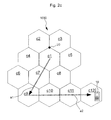
- Figure 2a schematically depicts an operational scenario of the terminal 10.
- figure 2a additionally depicts further radio cells c2, c3, c4, c5, c6, c7, c8, c9, c10, c11, c12.
- FIG. 2a the further cells depicted by figure 2a may be provided by further base stations (not shown) of the network 1000.
- the arrows a1, a2 of figure 2a indicate that terminal 10 is moving within the coverage area of the radio cells c1, .., c12.
- Arrow a1 indicates a substantially linear movement of the terminal 10 from the present radio cell c1 through cell c7 to cell c9.
- arrow a2 indicates a similar movement through cells c10, c11 to cell c12.
- Figure 2b depicts the terminal 10 as arrived within cell c9
- figure 2c depicts terminal 10 as arrived within cell c12.
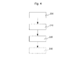
- Figure 4 schematically depicts a simplified flow chart of a method according to an embodiment.
- terminal 10 ( figure 2a ) maintains a first set of at least n many radio cells of said communications network 1000.
- the terminal 10 may determine said first set of radio cells, e.g. by per se known radio measurements. For example, terminal 10 may perform measurements of a reference signal receive power (RSRP) of various neighboring cells c2, c3, .. and may include those radio cells into the first set of radio cells which comprise the n many (presently 12) best RSRP values.
- RSRP reference signal receive power
- step 210 the terminal 10 determines whether a quality measurement value of a further radio cell c12, which is not comprised in the first set of radio cells, exceeds a predetermined second threshold, which is greater than said first threshold.
- Said step of determining 210 may e.g. comprise repeatedly (e.g., periodically or sporadically or according to a temporal random or pseudorandom pattern) performing RSRP measurements, wherein eventually radio cell c12 is detected or even found to comprise a quality measure value which exceeds said second threshold.
- the terminal 10 may modify, cf. step 220 of figure 4 , said first set of radio cells by including said further radio cell c12 to said first set, whereby a second set of radio cells is obtained.
- the currently worst radio cell previously comprised within the first set of radio cells i.e. the cell exhibiting the lowest RSRP value, may be cancelled from the first set to obtain the second set of radio cells.
- this second set of radio cells is reported in step 230 to a further device, e.g. to base station 20.
- the above-explained procedure according to the embodiments enables the terminal 10 to notify a base station 20 or further elements of the communications network 1000 from time to time on various radio cells detected in the course of its measurements, said cells being represented by the first set and the second set according to the embodiments.
- This advantageously enables to forward downlink data transmissions to the terminal 10 without precise knowledge as to its present geographical position on a strict per-radio cell basis.
- this advantageously enables to avoid frequent handovers as known from conventional systems, which are particularly inefficient for low data rate or even sporadic traffic from/to the terminal 10.
- the reporting of a modified set of radio cells such as e.g. the second set, according to an embodiment, cf. step 230 of figure 4 , only has to be performed with a comparatively low frequency thus not overburdening the air interface between terminal 10 and the base station 20.
- Said first set S1 - as well as one or more further sets S2, .. - may e.g. be stored in a storage device of the processing unit 11 of the terminal 10.
- Figure 5a exemplarily depicts an ordered table representing the first set S1 of radio cells.
- a first column col1 the cell identifier c1, c2, c3, ... is depicted.
- a second column col2 the associated quality measure value q1, q2, q3, ... for each cell c1, c2, c3, ... is depicted.
- an initial determination of the first set S1 of radio cells yields the table according to figure 5a , wherein a quality measure value q1 has been determined for the first cell c1, and so on.
- a reference signal receive power, RSRP as known from conventional LTE systems is used as a quality measure in the sense of the embodiments.
- step 200 the terminal maintains said first set S1 of 12 radio cells which may also be considered the strongest radio cells as seen from the position of the terminal 10 within cell c1 in terms of RSRP values.
- the terminal 10 may from time to time, i.e. periodically, determine 210 ( figure 4 ) whether a quality measure value (here: RSRP) of a further radio cell c12 presently not comprised in the first set S1 ( figure 5a ) exceeds a predetermined second threshold, which is greater than said first threshold.
- RSRP quality measure value
- the detected further radio cell c12 is associated with a better RSRP value as compared to the e.g. the RSRP value of at least the worst radio cell presently comprised in the first set S1.
- the terminal 10 modifies 220 ( figure 4 ) said first set S1 by including said further radio cell c12 to said first set S1, whereby a second set S2 is obtained, cf. figure 5b .
- said further cell c12 may be positioned in line of the table S2 corresponding to its RSRP value, so that the second S2 again comprises an ordered list or table of radio cells regarding their quality measure value.
- the second set S2 of radio cells, cf. figure 5b is exemplarily arranged in a table having columns, col3, col4 similar to the table of the first set S1 depicted by figure 5a .
- radio cell c12 is positioned in the first line of the table of figure 5b because it has the highest associated quality measure value q12.
- the determining step 210 of figure 4 has not yet yielded a further radio cell c12 exceeding the predetermined second threshold, such cell not yet being comprised in the first set, because the terminal 10 has passed the cells c1, c7, c9, c10, c11 which have already previously been included in the first set S1 ( figure 5a ) of radio cells.
- a further radio cell namely cell c12, is detected which exceeds the second threshold and which has not yet been included in the first set S1 of radio cells. This triggers the modification as already explained above, wherein the second set S2 of radio cells is obtained.
- step 230 as also already explained above, said second set S2 is reported to the base station 20 which is thereby enabled to efficiently forward downlink data transmissions to the terminal 10 exploiting the knowledge on the position of terminal 10 derived from the second set S2.
- the parameter n is chosen to be greater than 7, preferably greater than 10 to reduce the frequency of reporting dated sets of radio cells.
- the second set S2 of radio cells after obtaining the second set S2 of radio cells, again a single step of or periodically performed steps of determining in the sense of step 210 of figure 4 may be performed, i.e. the terminal 10 looking for yet another radio cell a quality measure value of which may exceed the second threshold, said another cell not yet being part of the presently considered second set S2.
- the second set S2 of radio cells may be modified as with the above-explained transition from set S1 to set S2, and so on.
- a new set of radio cells is derived by the terminal 10, it may advantageously be reported to any entity on the network side, preferably to a currently or previously serving base station 20.
- the terminal 10 is not required to report every such event or new set, respectively. Rather, according to a further embodiment, the terminal 10 may also influence, particularly reduce the rate of reporting 230.
- the terminal 10 may alter the parameter n and/or the parameter m, preferably depending on RSRP measurements and/or an operational state of said terminal 10 and/or the type and/or data rate (e.g., mean data rate) of traffic handled by the terminal 10.
- the type and/or data rate e.g., mean data rate
- the second threshold is greater than the quality measure value q1 of the radio cell c1 with the best quality measure value within said first set S1.
- the second threshold is chosen such that it is greater than the quality measure value q12 of the presently best radio cell 12 of said second set S2, and so on.
- a particular advantage of the principle according to the embodiments is based on the fact that said terminal 10 leaves a present set of radio cells, i.e. the first set S1, unmodified if the determination step 210 yields that a further detected radio cell 12 does not exceed the second threshold. In this case, likewise, no reporting to any external entities such as the base station 20 is necessary, because the structure and contents of the present set S1 of radio cells has not changed.
- the terminal 10 may determine the first set S1 based on radio measurements, as already explained above.
- the determination of the first set S1 of radio cells may consider control information received from a further device 20, 40 of the network 1000 and/or a geographical location of the terminal 10 and/or a geographical location of the base station 20 serving the terminal 10, and the like.
- terminal 10 may also modify the first set S1 and/or any further set S2, .. of radio cells depending on the above-referenced information.
- a further aspect of the embodiments is embodied by a transmission coordinator device 1010, which may e.g. be implemented within a base station 20 as depicted by figure 1 .
- the transmission coordinator device 1010 receives (cf. step 300 of the flow chart of Fig. 6 ) from a terminal 10 according to the embodiments the first set S1 and/or a second set S2.
- further potentially modified sets of radio cells which may be obtained by the terminal 10 based on a second set S2 and further determination steps 210 in the fashion of the determining step 210 of figure 4 , maybe received by the transmission coordinator device 1010.
- the transmission coordinator device 1010 forwards, cf. step 310 of Fig. 6 , downlink data to be transmitted to said terminal 10 depending on such received sets S1 and/or S2 or the like thus advantageously exploiting the location information provided therein.
- the principle of the embodiments enables a terminal 10 to be provided with downlink information in a precise and efficient manner without requiring numerous handover signaling messages as defined in conventional systems.
- a terminal 10 of a cellular communications network 1000 and/or a base station 20 or an entity comprising the functionality of the transmission coordinator device 1010 may be operated according to the principle according to the embodiments thus avoiding overburdening an air interface between devices 10, 20 and/or further interfaces such as e.g. an interface to an MME.
- the transmission coordinator device 1010 may forward, cf. step 310 of Fig. 6 , downlink data to be forwarded to the terminal 10 via a radio cell having the greatest quality measure value of the first set and/or the second set of radio cells.
- the transmission coordinator device 1010 may forward downlink data to the terminal 10 based via the radio cell c12, since it has the greatest quality measure value q12 as can be seen from the table representing the second set S2 of figure 5b .
- the device 1010 may forward, cf. step 310 of Fig. 6 , said downlink data to the terminal 10 via a radio cell associated with the last uplink traffic transmitted by the terminal 10.
- the device 1010 may forward, cf. step 310 of Fig. 6 , downlink data to said terminal 10 via a predetermined number of k' many radio cells of the first set S1 and/or the second set S2, wherein k' is greater than 1.
- device 1010 may perform paging within a location area associated with the terminal 10, wherein said location area may be larger than a UE centric tracking area.
- a first transmission attempt by device 1010 may be performed within a last reported best cell e.g. cell c1 in the case of a last reported set S1 or cell c12 in the case of a last reported set S2.
- a last reported best cell e.g. cell c1 in the case of a last reported set S1 or cell c12 in the case of a last reported set S2.
- these attempts for data transmission to terminal 10 may be followed by scheduled data transmissions within said k' many surrounding cells or paging within k' many surrounding cells and scheduled data transmission in one of said surrounding cells.
- the functionality of the device 1010 may e.g. be integrated into one or more base stations 20, 40 of the communications network.
- device 1010 or 20 may forward such set to other devices 40 such as e.g. neighboring bases stations or the like.
- the principle according to the embodiments is particularly beneficial for implementing 5G (fifth-generation) mobile communications networks, because different kind of handovers could be supported by providing the principle according to the embodiments.
- 5G fifth-generation
- the principle according to the embodiments may be applied for terminals engaged with high data volumes, e.g. video steaming or continuous transmissions, e.g. voice over 5G conventional handover (HO) processes or advanced HO process derived therefrom.
- HO handover
- sporadic small data services e.g. for instant messaging
- the principle according to the embodiments as exemplified by the process of Fig. 4 , may be applied.
- the principle according to the embodiments advantageously enables a new mobility concept which avoids "unnecessary" UE (user equipment) measurement reporting and handover signaling in an active state of the terminal 10 as long as the terminal 10 is moving within a specified area, e.g. within the coverage area of a set S1, S2 of radio cells explained above, which may also be denoted as a UE centric tracking area.
- a decision which handover mode (conventional or according to the principle of the embodiments) should be applied may be controlled by a base station 20 or a radio cloud by configuration of the mobile terminal 10 with respective handover settings.
- a transmission in downlink and uplink for said terminal 10 may occur as soon as data is available.
- a new radio cell as best cell not belonging to the set of 9 cells (as defined above)
- a new measurement report with e.g. 1+8 cells is transmitted, i.e. a new UE centric tracking area is defined by the mobile terminal.
- a 5G UE-centric concept i.e. the UE context, consisting of e.g. a UE temporary identifier (C-RNTI), UE control channel search space, security settings etc.
- C-RNTI UE temporary identifier
- UE control channel search space security settings etc.
- the UE context may be transferred from a base station 20, which has received a report on a cell set S1, S2 and/or the measurement information of the terminal 10, towards other base stations 40 ( Fig. 1 ), which may e.g. be located within the UE centric tracking area.
- a setup of tunnels between involved base stations associated e.g. with cell c1 and other cells c2, .. could be performed, thus exploiting backhaul signaling.
- a UE context, control channel search space may be known in all cells of the UE centric tracking area.
- a context fetch from each cell within a cluster in which the terminal 10 is transmitting uplink data may be performed.
- new data in downlink to be transmitted to the terminal 10 may be treated in the following order: first transmission attempt within a last reported best cell or the last cell with uplink traffic, optionally followed by scheduled data within k' many surrounding cells or paging within k' many surrounding cells and scheduled data in one cell, optionally followed by paging within the location area.
- the terminal 10 when a terminal 10 ( Fig. 1 ) is switched on in a radio cell c1, the terminal 10 may be configured, preferably by the base station 20, with a new measurement event "Ax".
- the Ax event if the Ax event is reported to the base station 20, it may include cell ids (e.g. physical cell id, PCI) of e.g. up to 8 cells which received signal level is above a defined threshold and other elements.
- the sets S1, S2 as explained above may comprise such cell ids, e.g. PCI values.
- a triggering condition of the event Ax followed by a reporting (cf. step 230 of figure 4 ) towards e.g. a base station 20, may be defined as: the terminal is in a coverage area of a cell c12 not listed within the last report (or set S1) and the received level of cell c12 is higher than the current received levels of the cells within the last report (S1).
- the terminal 10 will send a new (for example, initial) Ax event to the serving base station 20 of radio cell c1.
- a scheduled transmission of downlink and uplink data may be considered.
- an activity timer may be started in the base station 20 and/or the terminal 10 after reception or transmission of data is finalized.
- the terminal 10 may be shifted by the base station 20 or based on its own timer to a low-overhead connected state, i.e. no PMI (precoding matrix indicator), CQI (channel quality indicator) reports.
- a scheduled transmission may be performed.
- a RACH (random access channel) access with timing advance and the like may be performed by the terminal 10, optionally followed by a scheduling request.
- a transmission of received UE data from cell c9 towards cell c1 of base station 20 may be performed, as base station 20 may work as a mobility anchor for all data (downlink and uplink) within the UE centric tracking area.
- a scheduled transmission in downlink in cell 1 may be performed by the base station 20.
- the base station 20 may forward the downlink data to cells c2-c11, optionally followed by scheduled transmission(s) in downlink in cells c2-c11 or optionally followed by paging in cells c2-c11 (or any subset thereof), optionally followed by scheduling of the terminal in cell c10.
- downlink data may be forwarded to cells c1-c8 and c10-c11, wherein according to a further embodiment, scheduled transmission in downlink cells c1-c8 and c10-c11 may be performed and/or paging in cells c1-c8 and c10-c11 followed by scheduling of terminal 10 in cell c10-.
- a RACH access may take place and a new measurement report (e.g., a set S1 or S2 or the like) may be transmitted towards the base station providing cell c12.
- a new measurement report e.g., a set S1 or S2 or the like
- an Ax event triggering a reporting may comprise PCIs of radio cells above a defined received level (for example, considering RSRP) with PCI_last.
- information may be transmitted from the base station of cell c12 towards the other base station 20 of cell c1.
- Base station 20 may trigger a path switch to the base station of cell c12 towards MME.
- the principle according to the embodiments advantageously reduces a number of signaling messages (especially on the air interface and towards MME), and an efficient tracking of mobile terminals 10 (UEs) is enabled, which is particularly efficient with small data packet services (e.g. low data rate, non-real time, delay-tolerant and sporadic traffic), thus being well-suited for implementation in a 5G network.
- UEs mobile terminals 10
- any block diagrams herein represent conceptual views of illustrative circuitry embodying the principles of the invention.
- any flow charts, flow diagrams, state transition diagrams, pseudo code, and the like represent various processes which may be substantially represented in computer readable medium and so executed by a computer or processor, whether or not such computer or processor is explicitly shown.
Landscapes
- Engineering & Computer Science (AREA)
- Computer Networks & Wireless Communication (AREA)
- Signal Processing (AREA)
- Mobile Radio Communication Systems (AREA)
Priority Applications (5)
| Application Number | Priority Date | Filing Date | Title |
|---|---|---|---|
| EP15290086.6A EP3073784B1 (de) | 2015-03-27 | 2015-03-27 | Endgerät für ein zellulares kommunikationsnetzwerk und verfahren zum betrieb eines endgerätes |
| CN202010004629.9A CN111182599B (zh) | 2015-03-27 | 2016-01-27 | 用户设备以及网络元件 |
| CN201680014599.1A CN107409334B (zh) | 2015-03-27 | 2016-01-27 | 终端、终端操作方法、传输协调器设备、基站以及传输协调器设备的操作方法 |
| PCT/EP2016/051651 WO2016155903A1 (en) | 2015-03-27 | 2016-01-27 | Terminal, method of operating a terminal, transmission coordinator device, base station and method of operating a transmission coordinator device |
| US15/562,279 US10568008B2 (en) | 2015-03-27 | 2016-01-27 | Terminal, method of operating a terminal, transmission coordinator device, base station and method of operating a transmission coordinator device |
Applications Claiming Priority (1)
| Application Number | Priority Date | Filing Date | Title |
|---|---|---|---|
| EP15290086.6A EP3073784B1 (de) | 2015-03-27 | 2015-03-27 | Endgerät für ein zellulares kommunikationsnetzwerk und verfahren zum betrieb eines endgerätes |
Publications (2)
| Publication Number | Publication Date |
|---|---|
| EP3073784A1 true EP3073784A1 (de) | 2016-09-28 |
| EP3073784B1 EP3073784B1 (de) | 2020-09-16 |
Family
ID=53002633
Family Applications (1)
| Application Number | Title | Priority Date | Filing Date |
|---|---|---|---|
| EP15290086.6A Not-in-force EP3073784B1 (de) | 2015-03-27 | 2015-03-27 | Endgerät für ein zellulares kommunikationsnetzwerk und verfahren zum betrieb eines endgerätes |
Country Status (1)
| Country | Link |
|---|---|
| EP (1) | EP3073784B1 (de) |
Citations (2)
| Publication number | Priority date | Publication date | Assignee | Title |
|---|---|---|---|---|
| US20030040311A1 (en) * | 2001-08-16 | 2003-02-27 | Lg Electronics Inc. | Cell selection method of mobile terminal |
| WO2008085838A1 (en) * | 2007-01-04 | 2008-07-17 | Interdigital Technology Corporation | Method and apparatus for handover using a candidate set |
-
2015
- 2015-03-27 EP EP15290086.6A patent/EP3073784B1/de not_active Not-in-force
Patent Citations (2)
| Publication number | Priority date | Publication date | Assignee | Title |
|---|---|---|---|---|
| US20030040311A1 (en) * | 2001-08-16 | 2003-02-27 | Lg Electronics Inc. | Cell selection method of mobile terminal |
| WO2008085838A1 (en) * | 2007-01-04 | 2008-07-17 | Interdigital Technology Corporation | Method and apparatus for handover using a candidate set |
Non-Patent Citations (2)
| Title |
|---|
| "3rd Generation Partnership Project; Technical Specification Group Radio Access Network; Evolved Universal Terrestrial Radio Access (E-UTRA); Radio Resource Control (RRC); Protocol specification (Release 12)", 3GPP STANDARD; 3GPP TS 36.331, 3RD GENERATION PARTNERSHIP PROJECT (3GPP), MOBILE COMPETENCE CENTRE ; 650, ROUTE DES LUCIOLES ; F-06921 SOPHIA-ANTIPOLIS CEDEX ; FRANCE, vol. RAN WG2, no. V12.4.1, 7 January 2015 (2015-01-07), pages 1 - 410, XP050927575 * |
| "3rd Generation Partnership Project; Technical Specification Group Radio Access Network; Radio Resource Control (RRC); Protocol specification (Release 12)", 3GPP STANDARD; 3GPP TS 25.331, 3RD GENERATION PARTNERSHIP PROJECT (3GPP), MOBILE COMPETENCE CENTRE ; 650, ROUTE DES LUCIOLES ; F-06921 SOPHIA-ANTIPOLIS CEDEX ; FRANCE, vol. RAN WG2, no. V12.5.0, 25 March 2015 (2015-03-25), pages 1 - 2225, XP050928109 * |
Also Published As
| Publication number | Publication date |
|---|---|
| EP3073784B1 (de) | 2020-09-16 |
Similar Documents
| Publication | Publication Date | Title |
|---|---|---|
| EP3721655B1 (de) | Kommunikationsverfahren, vorrichtung und computerlesbares speichermedium für relaisvorrichtung | |
| JP6465238B2 (ja) | eNodeB、モビリティ管理装置、及びこれらの方法 | |
| KR102125786B1 (ko) | 핸드오버 방법, 기지국 및 단말 기기 | |
| CN108353330B (zh) | 用于实现移动性过程的方法和节点 | |
| US9560628B2 (en) | Method and node for paging in a radio access network | |
| US10568008B2 (en) | Terminal, method of operating a terminal, transmission coordinator device, base station and method of operating a transmission coordinator device | |
| EP3061314B1 (de) | Drahtloszugangsknoten und verfahren zur signalisierung der aggregation mehrerer benutzervorrichtungen über eine hub-benutzervorrichtung | |
| KR20180079404A (ko) | 무선 통신 네트워크에서의 시그널링을 관리하는 무선 디바이스, 무선 네트워크 노드 및 이의 수행 방법 | |
| EP3968696B1 (de) | Ng-basierte kontextfreigabe und datenweiterleitung für multihop-mobilität | |
| KR20170032395A (ko) | 자기-조직화 트래킹 영역들의 분산 구현 | |
| CN109792642B (zh) | 用于移动性参考信号的传输的控制的方法和装置 | |
| KR102209558B1 (ko) | 서비스 지시 방법, 기지국, 단말 및 시스템 | |
| US9794840B1 (en) | Systems and methods for determining access node candidates for handover of wireless devices | |
| US20220191808A1 (en) | Network node and method for managing power of cell reference symbols | |
| US9264960B1 (en) | Systems and methods for determinng access node candidates for handover of wireless devices | |
| US9813341B1 (en) | Systems and methods for routing data traffic based on network conditions | |
| EP3073784B1 (de) | Endgerät für ein zellulares kommunikationsnetzwerk und verfahren zum betrieb eines endgerätes | |
| US10129175B1 (en) | Systems and methods for performing carrier aggregation based on subframe configuration | |
| JP2017163495A (ja) | 通信装置 | |
| US9705739B1 (en) | Systems and methods for configuring a unique access node identifier | |
| US8929889B1 (en) | Handling of frequency bands in neighbor lists in wireless communication devices | |
| US10045151B1 (en) | Systems and methods for triggering transmission bundling for participant wireless devices of an antenna system | |
| US10542451B1 (en) | Systems and methods for managing conflicts between access node protocols | |
| US20250056452A1 (en) | Method and apparatus for performing handover | |
| US10075268B1 (en) | Systems and methods for performing carrier aggregation for a wireless device proximate to an antenna system |
Legal Events
| Date | Code | Title | Description |
|---|---|---|---|
| PUAI | Public reference made under article 153(3) epc to a published international application that has entered the european phase |
Free format text: ORIGINAL CODE: 0009012 |
|
| AK | Designated contracting states |
Kind code of ref document: A1 Designated state(s): AL AT BE BG CH CY CZ DE DK EE ES FI FR GB GR HR HU IE IS IT LI LT LU LV MC MK MT NL NO PL PT RO RS SE SI SK SM TR |
|
| AX | Request for extension of the european patent |
Extension state: BA ME |
|
| STAA | Information on the status of an ep patent application or granted ep patent |
Free format text: STATUS: REQUEST FOR EXAMINATION WAS MADE |
|
| 17P | Request for examination filed |
Effective date: 20170328 |
|
| RBV | Designated contracting states (corrected) |
Designated state(s): AL AT BE BG CH CY CZ DE DK EE ES FI FR GB GR HR HU IE IS IT LI LT LU LV MC MK MT NL NO PL PT RO RS SE SI SK SM TR |
|
| RAP1 | Party data changed (applicant data changed or rights of an application transferred) |
Owner name: ALCATEL LUCENT |
|
| STAA | Information on the status of an ep patent application or granted ep patent |
Free format text: STATUS: EXAMINATION IS IN PROGRESS |
|
| 17Q | First examination report despatched |
Effective date: 20180516 |
|
| GRAP | Despatch of communication of intention to grant a patent |
Free format text: ORIGINAL CODE: EPIDOSNIGR1 |
|
| STAA | Information on the status of an ep patent application or granted ep patent |
Free format text: STATUS: GRANT OF PATENT IS INTENDED |
|
| INTG | Intention to grant announced |
Effective date: 20190806 |
|
| GRAJ | Information related to disapproval of communication of intention to grant by the applicant or resumption of examination proceedings by the epo deleted |
Free format text: ORIGINAL CODE: EPIDOSDIGR1 |
|
| STAA | Information on the status of an ep patent application or granted ep patent |
Free format text: STATUS: EXAMINATION IS IN PROGRESS |
|
| GRAP | Despatch of communication of intention to grant a patent |
Free format text: ORIGINAL CODE: EPIDOSNIGR1 |
|
| STAA | Information on the status of an ep patent application or granted ep patent |
Free format text: STATUS: GRANT OF PATENT IS INTENDED |
|
| INTC | Intention to grant announced (deleted) | ||
| INTG | Intention to grant announced |
Effective date: 20200117 |
|
| GRAJ | Information related to disapproval of communication of intention to grant by the applicant or resumption of examination proceedings by the epo deleted |
Free format text: ORIGINAL CODE: EPIDOSDIGR1 |
|
| STAA | Information on the status of an ep patent application or granted ep patent |
Free format text: STATUS: EXAMINATION IS IN PROGRESS |
|
| GRAP | Despatch of communication of intention to grant a patent |
Free format text: ORIGINAL CODE: EPIDOSNIGR1 |
|
| STAA | Information on the status of an ep patent application or granted ep patent |
Free format text: STATUS: GRANT OF PATENT IS INTENDED |
|
| INTC | Intention to grant announced (deleted) | ||
| INTG | Intention to grant announced |
Effective date: 20200507 |
|
| GRAS | Grant fee paid |
Free format text: ORIGINAL CODE: EPIDOSNIGR3 |
|
| GRAA | (expected) grant |
Free format text: ORIGINAL CODE: 0009210 |
|
| STAA | Information on the status of an ep patent application or granted ep patent |
Free format text: STATUS: THE PATENT HAS BEEN GRANTED |
|
| AK | Designated contracting states |
Kind code of ref document: B1 Designated state(s): AL AT BE BG CH CY CZ DE DK EE ES FI FR GB GR HR HU IE IS IT LI LT LU LV MC MK MT NL NO PL PT RO RS SE SI SK SM TR |
|
| REG | Reference to a national code |
Ref country code: GB Ref legal event code: FG4D |
|
| REG | Reference to a national code |
Ref country code: CH Ref legal event code: EP |
|
| REG | Reference to a national code |
Ref country code: DE Ref legal event code: R096 Ref document number: 602015059117 Country of ref document: DE |
|
| REG | Reference to a national code |
Ref country code: IE Ref legal event code: FG4D |
|
| REG | Reference to a national code |
Ref country code: AT Ref legal event code: REF Ref document number: 1315308 Country of ref document: AT Kind code of ref document: T Effective date: 20201015 |
|
| PG25 | Lapsed in a contracting state [announced via postgrant information from national office to epo] |
Ref country code: BG Free format text: LAPSE BECAUSE OF FAILURE TO SUBMIT A TRANSLATION OF THE DESCRIPTION OR TO PAY THE FEE WITHIN THE PRESCRIBED TIME-LIMIT Effective date: 20201216 Ref country code: SE Free format text: LAPSE BECAUSE OF FAILURE TO SUBMIT A TRANSLATION OF THE DESCRIPTION OR TO PAY THE FEE WITHIN THE PRESCRIBED TIME-LIMIT Effective date: 20200916 Ref country code: NO Free format text: LAPSE BECAUSE OF FAILURE TO SUBMIT A TRANSLATION OF THE DESCRIPTION OR TO PAY THE FEE WITHIN THE PRESCRIBED TIME-LIMIT Effective date: 20201216 Ref country code: HR Free format text: LAPSE BECAUSE OF FAILURE TO SUBMIT A TRANSLATION OF THE DESCRIPTION OR TO PAY THE FEE WITHIN THE PRESCRIBED TIME-LIMIT Effective date: 20200916 Ref country code: FI Free format text: LAPSE BECAUSE OF FAILURE TO SUBMIT A TRANSLATION OF THE DESCRIPTION OR TO PAY THE FEE WITHIN THE PRESCRIBED TIME-LIMIT Effective date: 20200916 Ref country code: GR Free format text: LAPSE BECAUSE OF FAILURE TO SUBMIT A TRANSLATION OF THE DESCRIPTION OR TO PAY THE FEE WITHIN THE PRESCRIBED TIME-LIMIT Effective date: 20201217 |
|
| REG | Reference to a national code |
Ref country code: AT Ref legal event code: MK05 Ref document number: 1315308 Country of ref document: AT Kind code of ref document: T Effective date: 20200916 |
|
| REG | Reference to a national code |
Ref country code: NL Ref legal event code: MP Effective date: 20200916 |
|
| PG25 | Lapsed in a contracting state [announced via postgrant information from national office to epo] |
Ref country code: RS Free format text: LAPSE BECAUSE OF FAILURE TO SUBMIT A TRANSLATION OF THE DESCRIPTION OR TO PAY THE FEE WITHIN THE PRESCRIBED TIME-LIMIT Effective date: 20200916 Ref country code: LV Free format text: LAPSE BECAUSE OF FAILURE TO SUBMIT A TRANSLATION OF THE DESCRIPTION OR TO PAY THE FEE WITHIN THE PRESCRIBED TIME-LIMIT Effective date: 20200916 |
|
| REG | Reference to a national code |
Ref country code: LT Ref legal event code: MG4D |
|
| PG25 | Lapsed in a contracting state [announced via postgrant information from national office to epo] |
Ref country code: CZ Free format text: LAPSE BECAUSE OF FAILURE TO SUBMIT A TRANSLATION OF THE DESCRIPTION OR TO PAY THE FEE WITHIN THE PRESCRIBED TIME-LIMIT Effective date: 20200916 Ref country code: NL Free format text: LAPSE BECAUSE OF FAILURE TO SUBMIT A TRANSLATION OF THE DESCRIPTION OR TO PAY THE FEE WITHIN THE PRESCRIBED TIME-LIMIT Effective date: 20200916 Ref country code: PT Free format text: LAPSE BECAUSE OF FAILURE TO SUBMIT A TRANSLATION OF THE DESCRIPTION OR TO PAY THE FEE WITHIN THE PRESCRIBED TIME-LIMIT Effective date: 20210118 Ref country code: LT Free format text: LAPSE BECAUSE OF FAILURE TO SUBMIT A TRANSLATION OF THE DESCRIPTION OR TO PAY THE FEE WITHIN THE PRESCRIBED TIME-LIMIT Effective date: 20200916 Ref country code: SM Free format text: LAPSE BECAUSE OF FAILURE TO SUBMIT A TRANSLATION OF THE DESCRIPTION OR TO PAY THE FEE WITHIN THE PRESCRIBED TIME-LIMIT Effective date: 20200916 Ref country code: RO Free format text: LAPSE BECAUSE OF FAILURE TO SUBMIT A TRANSLATION OF THE DESCRIPTION OR TO PAY THE FEE WITHIN THE PRESCRIBED TIME-LIMIT Effective date: 20200916 Ref country code: EE Free format text: LAPSE BECAUSE OF FAILURE TO SUBMIT A TRANSLATION OF THE DESCRIPTION OR TO PAY THE FEE WITHIN THE PRESCRIBED TIME-LIMIT Effective date: 20200916 |
|
| PG25 | Lapsed in a contracting state [announced via postgrant information from national office to epo] |
Ref country code: PL Free format text: LAPSE BECAUSE OF FAILURE TO SUBMIT A TRANSLATION OF THE DESCRIPTION OR TO PAY THE FEE WITHIN THE PRESCRIBED TIME-LIMIT Effective date: 20200916 Ref country code: IS Free format text: LAPSE BECAUSE OF FAILURE TO SUBMIT A TRANSLATION OF THE DESCRIPTION OR TO PAY THE FEE WITHIN THE PRESCRIBED TIME-LIMIT Effective date: 20210116 Ref country code: ES Free format text: LAPSE BECAUSE OF FAILURE TO SUBMIT A TRANSLATION OF THE DESCRIPTION OR TO PAY THE FEE WITHIN THE PRESCRIBED TIME-LIMIT Effective date: 20200916 Ref country code: AT Free format text: LAPSE BECAUSE OF FAILURE TO SUBMIT A TRANSLATION OF THE DESCRIPTION OR TO PAY THE FEE WITHIN THE PRESCRIBED TIME-LIMIT Effective date: 20200916 Ref country code: AL Free format text: LAPSE BECAUSE OF FAILURE TO SUBMIT A TRANSLATION OF THE DESCRIPTION OR TO PAY THE FEE WITHIN THE PRESCRIBED TIME-LIMIT Effective date: 20200916 |
|
| REG | Reference to a national code |
Ref country code: DE Ref legal event code: R097 Ref document number: 602015059117 Country of ref document: DE |
|
| PG25 | Lapsed in a contracting state [announced via postgrant information from national office to epo] |
Ref country code: SK Free format text: LAPSE BECAUSE OF FAILURE TO SUBMIT A TRANSLATION OF THE DESCRIPTION OR TO PAY THE FEE WITHIN THE PRESCRIBED TIME-LIMIT Effective date: 20200916 |
|
| PLBE | No opposition filed within time limit |
Free format text: ORIGINAL CODE: 0009261 |
|
| STAA | Information on the status of an ep patent application or granted ep patent |
Free format text: STATUS: NO OPPOSITION FILED WITHIN TIME LIMIT |
|
| 26N | No opposition filed |
Effective date: 20210617 |
|
| PG25 | Lapsed in a contracting state [announced via postgrant information from national office to epo] |
Ref country code: SI Free format text: LAPSE BECAUSE OF FAILURE TO SUBMIT A TRANSLATION OF THE DESCRIPTION OR TO PAY THE FEE WITHIN THE PRESCRIBED TIME-LIMIT Effective date: 20200916 Ref country code: DK Free format text: LAPSE BECAUSE OF FAILURE TO SUBMIT A TRANSLATION OF THE DESCRIPTION OR TO PAY THE FEE WITHIN THE PRESCRIBED TIME-LIMIT Effective date: 20200916 |
|
| PG25 | Lapsed in a contracting state [announced via postgrant information from national office to epo] |
Ref country code: IT Free format text: LAPSE BECAUSE OF FAILURE TO SUBMIT A TRANSLATION OF THE DESCRIPTION OR TO PAY THE FEE WITHIN THE PRESCRIBED TIME-LIMIT Effective date: 20200916 Ref country code: MC Free format text: LAPSE BECAUSE OF FAILURE TO SUBMIT A TRANSLATION OF THE DESCRIPTION OR TO PAY THE FEE WITHIN THE PRESCRIBED TIME-LIMIT Effective date: 20200916 |
|
| REG | Reference to a national code |
Ref country code: CH Ref legal event code: PL |
|
| REG | Reference to a national code |
Ref country code: BE Ref legal event code: MM Effective date: 20210331 |
|
| PG25 | Lapsed in a contracting state [announced via postgrant information from national office to epo] |
Ref country code: IE Free format text: LAPSE BECAUSE OF NON-PAYMENT OF DUE FEES Effective date: 20210327 Ref country code: LI Free format text: LAPSE BECAUSE OF NON-PAYMENT OF DUE FEES Effective date: 20210331 Ref country code: LU Free format text: LAPSE BECAUSE OF NON-PAYMENT OF DUE FEES Effective date: 20210327 Ref country code: CH Free format text: LAPSE BECAUSE OF NON-PAYMENT OF DUE FEES Effective date: 20210331 |
|
| PGFP | Annual fee paid to national office [announced via postgrant information from national office to epo] |
Ref country code: GB Payment date: 20220203 Year of fee payment: 8 Ref country code: DE Payment date: 20220203 Year of fee payment: 8 |
|
| PGFP | Annual fee paid to national office [announced via postgrant information from national office to epo] |
Ref country code: FR Payment date: 20220209 Year of fee payment: 8 |
|
| PG25 | Lapsed in a contracting state [announced via postgrant information from national office to epo] |
Ref country code: BE Free format text: LAPSE BECAUSE OF NON-PAYMENT OF DUE FEES Effective date: 20210331 |
|
| PG25 | Lapsed in a contracting state [announced via postgrant information from national office to epo] |
Ref country code: HU Free format text: LAPSE BECAUSE OF FAILURE TO SUBMIT A TRANSLATION OF THE DESCRIPTION OR TO PAY THE FEE WITHIN THE PRESCRIBED TIME-LIMIT; INVALID AB INITIO Effective date: 20150327 |
|
| PG25 | Lapsed in a contracting state [announced via postgrant information from national office to epo] |
Ref country code: CY Free format text: LAPSE BECAUSE OF FAILURE TO SUBMIT A TRANSLATION OF THE DESCRIPTION OR TO PAY THE FEE WITHIN THE PRESCRIBED TIME-LIMIT Effective date: 20200916 |
|
| REG | Reference to a national code |
Ref country code: DE Ref legal event code: R119 Ref document number: 602015059117 Country of ref document: DE |
|
| GBPC | Gb: european patent ceased through non-payment of renewal fee |
Effective date: 20230327 |
|
| PG25 | Lapsed in a contracting state [announced via postgrant information from national office to epo] |
Ref country code: GB Free format text: LAPSE BECAUSE OF NON-PAYMENT OF DUE FEES Effective date: 20230327 |
|
| PG25 | Lapsed in a contracting state [announced via postgrant information from national office to epo] |
Ref country code: GB Free format text: LAPSE BECAUSE OF NON-PAYMENT OF DUE FEES Effective date: 20230327 Ref country code: FR Free format text: LAPSE BECAUSE OF NON-PAYMENT OF DUE FEES Effective date: 20230331 Ref country code: DE Free format text: LAPSE BECAUSE OF NON-PAYMENT OF DUE FEES Effective date: 20231003 |
|
| PG25 | Lapsed in a contracting state [announced via postgrant information from national office to epo] |
Ref country code: MK Free format text: LAPSE BECAUSE OF FAILURE TO SUBMIT A TRANSLATION OF THE DESCRIPTION OR TO PAY THE FEE WITHIN THE PRESCRIBED TIME-LIMIT Effective date: 20200916 |
|
| PG25 | Lapsed in a contracting state [announced via postgrant information from national office to epo] |
Ref country code: MT Free format text: LAPSE BECAUSE OF FAILURE TO SUBMIT A TRANSLATION OF THE DESCRIPTION OR TO PAY THE FEE WITHIN THE PRESCRIBED TIME-LIMIT Effective date: 20200916 |
|
| PG25 | Lapsed in a contracting state [announced via postgrant information from national office to epo] |
Ref country code: TR Free format text: LAPSE BECAUSE OF FAILURE TO SUBMIT A TRANSLATION OF THE DESCRIPTION OR TO PAY THE FEE WITHIN THE PRESCRIBED TIME-LIMIT Effective date: 20200916 |