EP3073755B1 - Optical packet drop structure and associated node - Google Patents
Optical packet drop structure and associated node Download PDFInfo
- Publication number
- EP3073755B1 EP3073755B1 EP15290085.8A EP15290085A EP3073755B1 EP 3073755 B1 EP3073755 B1 EP 3073755B1 EP 15290085 A EP15290085 A EP 15290085A EP 3073755 B1 EP3073755 B1 EP 3073755B1
- Authority
- EP
- European Patent Office
- Prior art keywords
- optical
- output
- linked
- input
- packets
- Prior art date
- Legal status (The legal status is an assumption and is not a legal conclusion. Google has not performed a legal analysis and makes no representation as to the accuracy of the status listed.)
- Active
Links
- 230000003287 optical effect Effects 0.000 title claims description 300
- 230000010287 polarization Effects 0.000 claims description 41
- 230000001427 coherent effect Effects 0.000 claims description 23
- 230000002457 bidirectional effect Effects 0.000 claims description 21
- 230000000903 blocking effect Effects 0.000 claims description 11
- XUIMIQQOPSSXEZ-UHFFFAOYSA-N Silicon Chemical group [Si] XUIMIQQOPSSXEZ-UHFFFAOYSA-N 0.000 claims description 4
- 229910052710 silicon Inorganic materials 0.000 claims description 4
- 239000010703 silicon Substances 0.000 claims description 4
- 238000010586 diagram Methods 0.000 description 9
- 239000013307 optical fiber Substances 0.000 description 7
- 230000009977 dual effect Effects 0.000 description 4
- 238000001514 detection method Methods 0.000 description 3
- 230000010354 integration Effects 0.000 description 3
- 230000006735 deficit Effects 0.000 description 2
- 238000000034 method Methods 0.000 description 2
- 230000001360 synchronised effect Effects 0.000 description 2
- 239000004065 semiconductor Substances 0.000 description 1
Images


Classifications
-
- H—ELECTRICITY
- H04—ELECTRIC COMMUNICATION TECHNIQUE
- H04J—MULTIPLEX COMMUNICATION
- H04J14/00—Optical multiplex systems
- H04J14/02—Wavelength-division multiplex systems
- H04J14/0201—Add-and-drop multiplexing
- H04J14/0215—Architecture aspects
- H04J14/0216—Bidirectional architectures
-
- H—ELECTRICITY
- H04—ELECTRIC COMMUNICATION TECHNIQUE
- H04Q—SELECTING
- H04Q11/00—Selecting arrangements for multiplex systems
- H04Q11/0001—Selecting arrangements for multiplex systems using optical switching
- H04Q11/0005—Switch and router aspects
-
- H—ELECTRICITY
- H04—ELECTRIC COMMUNICATION TECHNIQUE
- H04J—MULTIPLEX COMMUNICATION
- H04J14/00—Optical multiplex systems
- H04J14/06—Polarisation multiplex systems
-
- H—ELECTRICITY
- H04—ELECTRIC COMMUNICATION TECHNIQUE
- H04Q—SELECTING
- H04Q11/00—Selecting arrangements for multiplex systems
- H04Q11/0001—Selecting arrangements for multiplex systems using optical switching
- H04Q11/0005—Switch and router aspects
- H04Q2011/0007—Construction
- H04Q2011/0009—Construction using wavelength filters
-
- H—ELECTRICITY
- H04—ELECTRIC COMMUNICATION TECHNIQUE
- H04Q—SELECTING
- H04Q11/00—Selecting arrangements for multiplex systems
- H04Q11/0001—Selecting arrangements for multiplex systems using optical switching
- H04Q11/0005—Switch and router aspects
- H04Q2011/0007—Construction
- H04Q2011/0016—Construction using wavelength multiplexing or demultiplexing
-
- H—ELECTRICITY
- H04—ELECTRIC COMMUNICATION TECHNIQUE
- H04Q—SELECTING
- H04Q11/00—Selecting arrangements for multiplex systems
- H04Q11/0001—Selecting arrangements for multiplex systems using optical switching
- H04Q11/0005—Switch and router aspects
- H04Q2011/0007—Construction
- H04Q2011/0018—Construction using tunable transmitters or receivers
-
- H—ELECTRICITY
- H04—ELECTRIC COMMUNICATION TECHNIQUE
- H04Q—SELECTING
- H04Q11/00—Selecting arrangements for multiplex systems
- H04Q11/0001—Selecting arrangements for multiplex systems using optical switching
- H04Q11/0005—Switch and router aspects
- H04Q2011/0007—Construction
- H04Q2011/0035—Construction using miscellaneous components, e.g. circulator, polarisation, acousto/thermo optical
-
- H—ELECTRICITY
- H04—ELECTRIC COMMUNICATION TECHNIQUE
- H04Q—SELECTING
- H04Q11/00—Selecting arrangements for multiplex systems
- H04Q11/0001—Selecting arrangements for multiplex systems using optical switching
- H04Q11/0005—Switch and router aspects
- H04Q2011/0037—Operation
- H04Q2011/0049—Crosstalk reduction; Noise; Power budget
Definitions
- the present invention relates to the field of wavelength division multiplexing (WDM) optical network with packet granularity capability and more particularly to the dropping means of the optical packet switching node enabling to switch the packets to be dropped toward a receiver to be detected.
- WDM wavelength division multiplexing
- optical packets are transmitted within time slots and, in each node called optical packet switching node, optical packets may be dropped and added to the optical links of the network.
- a demultiplexer to separate the different wavelength channels comprising the packets.
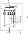
- Fig.1 represents an optical packet switching node 100 according to an embodiment of the state of the art. It comprises a dropping optical coupler or optical splitter 3 comprising an input 301 linked to the input 2 of the node 100, a first output 302 linked to a receiving unit 5 which is configured for detecting the dropped packets and a second output 303 linked to the input 601 of a switching structure 6.
- the dropping optical coupler 3 is configured for transmitting a wavelength division multiplexed (WDM) signal received on its input 301 to both its first 302 and its second 303 outputs.
- WDM wavelength division multiplexed
- the switching structure 6 comprises a demultiplexer 7 configured for demultiplexing the multiplexed channels of the WDM signal into a plurality of channels which are transmitted respectively to a plurality of optical gates 9 configured for blocking or letting pass the packets of the time slots of each channel.
- the different channels are re-multiplexed by a multiplexer 11.
- the node 100 also comprises a transmitting unit 15 which is configured to emit signals corresponding to the added packets aimed at being inserted in the packet positions freed or emptied by the optical gates 9.
- An adding optical coupler 13 comprising a first input 131 linked to the output 602 of the switching structure 6, a second input 132 linked to a transmitting unit 15 and an output 133 linked to the output 18 of the node 100.
- the said adding optical coupler 13 is configured to mix the signals received from its first 131 and its second 132 inputs and for transmitting the mixed signal to its output 133.
- the receiving unit 5 comprises one or several fast tunable coherent receivers configured for tuning their local oscillator to the wavelength of the channel comprising the packet that has to be dropped.
- the crosstalk undergone by the detected signal increases with the number of received channels so that crosstalk impairments become very high for high throughput networks comprising a high number of wavelength channels, for example 40 or more.
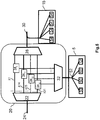
- Fig.2 represents an optical packet switching node 100 according to another embodiment of the state of the art. It differs from the embodiment of fig.1 in that there is no dropping optical coupler but the optical fibers of the switching structure 6 corresponding to the different channels are linked respectively to dropped optical fibers 8 for example by an optical splitter, the said dropped optical fibers 8 being linked respectively to a receiving unit 5 which can comprise one or a plurality of coherent or non-coherent receivers.
- the problem with such architecture is that it is not possible to implement in a cost-effective way the switching structure 6 within an integrated circuit for example a silicon based equipment due to the high number of connectors required to link the different dropped optical fibers 8 to the receiver 5.
- NPL documents entitled 'Successful demonstration of the compatibility of optical packet and wavelength circuit switching in optical networks' (35TH EUROPEAN CONFERENCE ON OPTICAL COMMUNICATION, 2009. ECOC '09, VIENNA, AUSTRIA, IEEE, PISCATAWAY, NJ, USA ) and 'Packet OADMs for the next generation of ring networks' (BELL LABS TECHNICAL JOURNAL, WILEY, CA, US ) disclose such embodiment of the state of the art using semiconductor optical amplifiers as optical gates 9.
- the present invention refers to an optical packet drop structure of an optical packet switching node of a wavelength division multiplexing optical network, as defined in claim 1.
- the switching means comprise a plurality of optical switches, an optical switch comprising an input linked to a respective output of the wavelength demultiplexer, a first output linked to a respective input of the first wavelength multiplexer and a second output linked to a respective input of the second wavelength multiplexer.
- the demultiplexer and the first multiplexer are combined in a single bidirectional device comprising a multiplexed input/output configured to be linked to an optical circulator linked to both an input optical link and an output optical link and a plurality of demultiplexed inputs/outputs, the packet drop structure comprising a plurality of optical reflectors linked respectively to the plurality of demultiplexed inputs/outputs via the switching means, the said switching means being configured for switching optical packets transmitted by a demultiplexed input/output of the bidirectional device toward an optical reflector and/or toward an input of the second wavelength multiplexer.
- the switching means comprise a plurality of optical switches comprising an input linked to a respective demultiplexed input/output of the bidirectional device, a first output linked to a respective optical reflector and a second output linked to a respective input of the second wavelength multiplexer.
- an optical switch comprises:
- the first optical gate is configured to let pass the optical packets aimed at being broadcasting toward another node of the wavelength division multiplexing optical network and to filter out the other optical packets and the second optical gate is configured to let pass the optical packets aimed at being dropped in the said optical packet switching node and also configured to filter out the other optical packets.
- the packet drop structure is integrated within a silicon based element.
- the embodiments of the present invention also refer to an optical packet switching node linked to an input link and an output link and comprising at least one optical packet drop structure.
- the optical packet switching node also comprises an optical circulator linked to the input link, to the output link and to the multiplexed input/ouput of the bidirectional device.
- the optical packet switching node comprises at least one coherent receiver linked to the output of the second multiplexer, the said, at least one, coherent receiver comprising a local oscillator configured to be tuned to the wavelength on which an optical packet to be detected is transmitted.
- the optical packet switching node comprises one non-coherent receiver linked to the output of the second multiplexer.
- the optical packet switching node comprises at least two non-coherent receivers, a non-coherent receiver being linked to the output of the second multiplexer via an optical filter, the said optical filter being configured to let pass the optical packets transmitted on a wavelength corresponding to the wavelength detected by the non-coherent receiver and to filter out the other optical packets.
- the optical packet switching node comprises at least one tunable laser source configured to be linked to the output link for transmitting optical packets toward other optical packet switching nodes on wavelength channels comprising free packet positions.
- the optical packet switching node comprises:
- the demultiplexing unit and the first multiplexing unit are combined in a single bidirectional unit.
- the elements having the same reference correspond to elements having a similar function.
- the number designates the class of elements having a common function and the index defines a particular element of the class.
- the reference 60 refers to the reflectors in general or to a reflector among other reflectors whereas the reference 601 refers to a particular reflector.
- WDM Wavelength Division Multiplexing
- time slot in a packet stream transmitted in a channel refers to a time interval wherein a packet is inserted
- dropped packet refers to a packet for which the current node is the egress node so that the said packet is detected by a receiver and the data of the packet are decoded by the receiver. Inversely, the non-dropped packets are transmitted transparently toward another node.
- the term “broadcasted packet” refers to a packet that has to be sent to another node so that the said packet is transmitted transparently to the output of the node.
- the embodiments of the present invention refer to a packet drop structure 20 of an optical packet switching node 101 comprising:
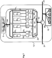
- Fig.3 represents an optical packet switching node 101 of a wavelength division multiplexing optical network comprising a plurality of nodes 101.
- the optical packet switching node 101 comprises an optical packet drop structure 20 which comprises:
- the node 101 also comprises a receiving unit 5 comprising at least one (three in the present case) receivers 50 and a transmitting unit 15.
- Fig.4 represents an exemplary embodiment of an optical switch 34 comprising:
- an optical packet received at the input of the optical switch 34 is either transmitted toward the first output 34b 1 or toward the second output 34b 2 or toward both outputs 34b 1 and 34b 2 (it is also technically possible to block the received packet on both outputs 34b 1 and 34b 2 ).
- Such architecture for the optical switches 34 enables a fast switching between the different configurations and does not add any crosstalk in the transmitted signal however, other configurations of optical switches may also be used within the scope of the present invention.
- the optical switches 34 located on each channel between the demultiplexer 22 and the multiplexer 28 enable to transmit only the dropped packets toward the second multiplexer 32 and therefore the receiving unit 5.
- the number of packets reaching a receiver of the receiving unit 5 is therefore limited which allows limiting the crosstalk in the case of a coherent receiver.
- Non-coherent receivers may also be used for the detection of the dropped packets. In such case, if more than one receiver is used, a filter, configured for selecting a wavelength channel comprising a dropped packet, is implemented at the input of the receiver.
- the number of receivers may vary depending on the number of dropped packets which need to be detected simultaneously. If only one non-coherent receiver is used, only one packet from a single wavelength channel corresponding to a waveguide 26 is dropped at a time so that no filter is necessary.
- the second multiplexer 32 enables to transmit all the dropped packets on a single optical link 40, for example an optical fiber, toward the receiving unit 5 so that an integration of the optical packet drop structure 20 requires only three connectors, a first connector 42 for the input optical link 24, a second connector 44 for the output optical link 30 and a third connector 46 for the connection 40 to the receiving unit 5.
- the optical packet drop structure 20 can therefore be integrated within a silicon based element or any other photonic integrated circuit.
- optical packet drop structure 20 To better understand this first embodiment, an example of functioning of the optical packet drop structure 20 will now be described based on fig.5 .
- the optical links of the network such as the input or the output optical links, transmit forty WDM channels and that four optical packets can be dropped simultaneously (during the same time slot) in each node (other numbers of channels and dropped packets could have been chosen and the number of dropped packets is not necessarily the same in each node).
- Each channel transmits an optical signal which is divided in time slots comprising the successive optical packets.
- the time slots of the different channels are synchronized.
- forty optical packets are transmitted through a link of the network.
- the forty channels are demultiplexed so that the optical signals of the forty channels ⁇ 1, ⁇ 2... ⁇ 40 are transmitted on forty separated optical waveguides 26 linked respectively to 40 optical switches 34.
- the corresponding optical switches 34 1 , 34 14 , 34 25 and 34 31 are configured so that the second optical gate 38 2 located at the second output 34b 2 let the received packet pass toward the second multiplexer 32 and the first optical gate 38 1 located at the first output 34 b1 is configured to block or filter out the received optical packet.
- both the first 38 1 and the second 38 2 optical gates can be configured to let the received optical packet pass.
- the associated optical switches 34 (not represented in fig.5 ) are configured so that the first optical gate 38 1 lets the received packet toward the first multiplexer pass and the second optical gate 38 2 blocks the received packet.
- only 4 packets transmitted respectively on the channels ⁇ 1, ⁇ 14, ⁇ 25 and ⁇ 31 are transmitted to the second multiplexer 32.
- These four channels ⁇ 1, ⁇ 14, ⁇ 25 and ⁇ 31 are then multiplexed and transmitted toward the receiving unit 5.
- the receiving unit 5 comprises four coherent receivers 50 and an optical splitter 52 to transmit the multiplexed signal toward the four coherent receivers 50.
- Each coherent receiver comprise a local oscillator and the four local oscillators are configured to be tuned respectively to the four wavelengths corresponding to the four channels ⁇ 1, ⁇ 14, ⁇ 25 and ⁇ 31.
- four packet positions have been freed on the said channels so that four new packets can be inserted by a tunable transmitter or tunable transmitters such as four tunable laser sources, for example fast tunable lasers 54 of the transmitting unit 15.
- the tunable transmitters may also be implemented as a plurality of fixed laser sources corresponding to the plurality of wavelength channel (or a part of the plurality of wavelength channels).
- the demultiplexer 22 and the second multiplexer 28 of the first embodiment are combined in a single bidirectional device 58 comprising a multiplexed input/output 58a linked to an optical circulator 56 linked to both the input optical link 24 and the output optical link 30 and a plurality of demultiplexed inputs/outputs 58b.
- the elements 22, 28, 32 and 58 can be the same but only the element 58 is used in both directions.
- the optical packet drop structure 20 also comprises:
- the input 34a of the plurality of optical switches 34 is linked respectively to the plurality of demultiplexed inputs/outputs 58b of the bidirectional device 58.
- the first output 34b 1 of the optical switches 34 is linked to an optical reflector 60 and the second output 34b 2 is linked to an input 32a of the multiplexer 32.
- the optical switches 34 are configured in the same way as in the first embodiment so that if a received packet has to only be broadcasted toward another node of the network, the first optical gate 38 1 is configured to let the optical packet received on the input pass toward the reflector 60 and the second optical gate 38 2 is configured to filter out the packet.
- the second optical gate 38 2 is configured to let the packet pass toward the multiplexer 32 and the first optical gate 38 1 is set to block the packet.
- both the first 38 1 and the second 38 2 optical gates are configured to let the packet pass.
- a broadcasted packet is sent by the optical switch 34 toward a reflector 60 to be sent back to the bidirectional device 58 and then transmitted to the output link 30 via the optical circulator 56 whereas a dropped packet is sent by the optical switch 34 toward the multiplexer 32 to be multiplexed and then transmitted to a receiving unit 5 for the detection.
- the receiving unit 5 is also similar to the receiving unit described in the first embodiment. This second embodiment provides some advantages with respect to the first embodiment. Indeed, the optical packet drop structure 20 requires only two connectors:
- the optical links of the network such as the input or the output optical links, transmit forty WDM channels and that four optical packets are dropped in each node (other numbers of channels and dropped packets could have been chosen and the number of dropped packets is not necessarily the same in each node).
- Each channel transmits an optical signal which is divided in time slots comprising the successive optical packets.
- the time slots of the different channels are synchronized.
- forty optical packets are transmitted through a link of the network.
- the optical signal received from the input optical link 24 by the optical circulator 56 are transmitted to the input/output 58a of the bidirectional device 58.
- the forty channels are demultiplexed so that the optical signals of the forty channels ⁇ 1, ⁇ 2... ⁇ 40 are transmitted on 40 separated optical waveguides 26 linked respectively to forty optical switches 34.
- the corresponding optical switches 34 1 , 34 14 , 34 25 and 34 31 are configured so that the second optical gate 38 2 located at the second output 34 b2 let the received packet pass toward the multiplexer 32 and the first optical gate 38 1 located at the first output 34 b1 is configured to block or filter out the received optical packet.
- both the first 38 1 and the second 38 2 optical gates can be configured to let the received optical packet pass.
- the associated optical switches 34 (not represented in fig.7 ) are configured so that the first optical gate 38 1 lets the received packet pass toward the optical reflector 60 and the second optical gate 38 2 blocks the received packet.
- only four packets transmitted respectively on the channels ⁇ 1, ⁇ 14, ⁇ 25 and ⁇ 31 are transmitted to the multiplexer 32. These four channels ⁇ 1, ⁇ 14, ⁇ 25 and ⁇ 31 are then multiplexed and transmitted toward the receiving unit 5.
- the receiving unit 5 comprises four coherent receivers 50 and an optical splitter 52 to transmit the multiplexed signal toward the four coherent receivers 50.
- the coherent receivers are tuned respectively to the 4 wavelength corresponding to the four channels ⁇ 1, ⁇ 14, ⁇ 25 and ⁇ 31.
- the optical packet drop structures 20 described before may also be used with optical signals comprising a modulation format with a plurality of spatial modes and/or polarizations.
- the node 101 comprises a plurality of optical packet drop structures 20, a demultiplexing unit 70, 82, a first multiplexing unit 74, 82 and a second multiplexing unit 78, 86.
- the number of optical packet drop structures 20 corresponds to the number of spatial mode and polarizations.
- the demultiplexing unit 70, 82 configured for demultiplexing the different spatial modes and/or polarizations is added at the input 101a of the node 101 to separate the different polarizations and/or spatial modes of the signal received on the input optical link 24 and each spatial mode and/or polarization is transmitted toward an optical packet drop structure 20.
- the broadcasted packets transmitted at the output of the first multiplexer 28 of the optical packet drop structures 20 are remultiplexed by the first multiplexing unit 74, 82 to be sent toward the output link 30.
- the dropped packets transmitted at the output of the second multiplexer 32 of the optical packet drop structures 20 are remultiplexed by the second multiplexing unit 78, 86 to be sent to the receiving unit 5.
- the demultiplexing unit 70, 82 comprises a polarization demultiplexer with a plurality of outputs corresponding to the plurality of polarizations and a plurality of spatial mode demultiplexers located respectively at the outputs of the polarization demultiplexer.
- the first and second multiplexing units comprise a plurality of spatial mode multiplexers combined with a polarization multiplexer.
- the demultiplexing unit 70, 82 may comprises a spatial mode demultiplexer with a plurality of outputs corresponding to the plurality of spatial modes and a plurality of polarization demultiplexers located respectively at the outputs of the spatial mode demultiplexer.
- the first and second multiplexing unit comprise a plurality of spatial mode multiplexers combined with a polarization multiplexer.
- the demultiplexing unit and the first multiplexing unit can be combined in a single bidirectional unit 82.
- Fig.8 represents an example of a node 101 configured for receiving signals with a dual polarization modulation format.
- the node 101 comprises two optical packet drop structures 20, a demultiplexing unit 70 comprising a polarization demultiplexer 72 with an input 72a linked to the input link 24 via an input 70a of the demultiplexing 70, a first output 72b 1 linked to the input 20a of an optical packet drop structure 20 via a first output 70b 1 of the demultiplexing unit 70 and a second output 72b 2 linked to the input 20a of the other optical packet drop structure 20 via a second output 70b 2 of the demultiplexing unit 70.
- the polarization demultiplexer 72 being configured for sending the part of the received signal corresponding to the first polarization on its first output 72b 1 and the part of the received signal corresponding to the second polarization on its second output 72b 2 .
- Both optical packet drop structures process both signals as described previously.
- the first output 20b 1 of the optical packet drop structures 20 are linked to a first multiplexing unit 74 comprising a polarization multiplexer 76 for remultiplexing both polarizations and sending the remultiplexed signal comprising the broadcasted packets toward the output link 30.
- the second output 20b 2 of the optical packet drop structures 20 are linked to a second multiplexing unit 78 comprising a polarization multiplexer 80 for remultiplexing both polarization and sending the remultiplexed signal comprising the dropped packets toward the receiving unit 5.
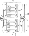
- Fig.9 represents an example of a node 101 configured for receiving signals with a dual polarization modulation format in the case of optical packet drop structures 20 according to the second embodiment described previously.
- the node 101 comprises two optical packet drop structures 20, a bidirectional unit 82 comprising a polarization multiplexer/demultiplexer 84 with a multiplexed input/output 84a linked to the optical coupler 56 via an input/output 82a of the bidirectional unit 82, a first demultiplexed input/output 84b 1 linked to the input/output 20a' of an optical packet drop structure 20 and a second demultiplexed input/output 84b 2 linked to the input/output 20a' of the other optical packet drop structure 20.
- the polarization multiplexer/demultiplexer 84 being configured for sending the part of the signal received from the optical circulator 56 corresponding to the first polarization on its first output 84b 1 and the part of the signal received from the optical circulator 56 corresponding to the second polarization on its second output 84b 2 .
- Both optical packet drop structures 20 process both signals as described previously.
- the output 20b of the optical packet drop structures 20 are linked to a multiplexing unit 86 comprising a polarization multiplexer 88 for remultiplexing both polarization and sending the remultiplexed signal comprising the dropped packets toward the receiving unit 5.
- a transmitting unit 15 enables to add packets in the free packets positions (for each time slot) of both polarizations.
- the embodiments described herein enables to provide an optical packet drop structure wherein the crosstalk at the receiver is reduced and which can be implemented in an integrated chip due to the low number of connectors required for linking the optical packet drop structure to the other elements of the node.
- such configuration combined with the proposed configuration for the switching means enables a fast reconfiguration of the switches without introducing impairments to the optical signal so that packet granularity with high throughput signals can be achieved.
- optical packet drop structures may also be used with optical signals comprising multiple spatial modes and/or multiple polarizations, a packet drop structure processing a signal corresponding to one spatial mode of one polarization, the different spatial modes and polarizations being separated before being transmitted to the different optical drop structure and remultiplexed to be sent to the receivers or the output link.
Landscapes
- Engineering & Computer Science (AREA)
- Computer Networks & Wireless Communication (AREA)
- Signal Processing (AREA)
- Optical Communication System (AREA)
Description
- The present invention relates to the field of wavelength division multiplexing (WDM) optical network with packet granularity capability and more particularly to the dropping means of the optical packet switching node enabling to switch the packets to be dropped toward a receiver to be detected.
- Indeed, in network with packet granularity capability, optical packets are transmitted within time slots and, in each node called optical packet switching node, optical packets may be dropped and added to the optical links of the network. To achieve such dropping, it is known to use a demultiplexer to separate the different wavelength channels comprising the packets.
-
Fig.1 represents an opticalpacket switching node 100 according to an embodiment of the state of the art. It comprises a dropping optical coupler oroptical splitter 3 comprising aninput 301 linked to theinput 2 of thenode 100, afirst output 302 linked to areceiving unit 5 which is configured for detecting the dropped packets and asecond output 303 linked to theinput 601 of aswitching structure 6. The droppingoptical coupler 3 is configured for transmitting a wavelength division multiplexed (WDM) signal received on itsinput 301 to both its first 302 and its second 303 outputs. Theswitching structure 6 comprises ademultiplexer 7 configured for demultiplexing the multiplexed channels of the WDM signal into a plurality of channels which are transmitted respectively to a plurality ofoptical gates 9 configured for blocking or letting pass the packets of the time slots of each channel. At the output of theoptical gates 9, the different channels are re-multiplexed by amultiplexer 11. Thenode 100 also comprises atransmitting unit 15 which is configured to emit signals corresponding to the added packets aimed at being inserted in the packet positions freed or emptied by theoptical gates 9. An addingoptical coupler 13 comprising afirst input 131 linked to theoutput 602 of theswitching structure 6, asecond input 132 linked to atransmitting unit 15 and anoutput 133 linked to theoutput 18 of thenode 100. The said addingoptical coupler 13 is configured to mix the signals received from its first 131 and its second 132 inputs and for transmitting the mixed signal to itsoutput 133. In such embodiment, thereceiving unit 5 comprises one or several fast tunable coherent receivers configured for tuning their local oscillator to the wavelength of the channel comprising the packet that has to be dropped. However, in such receivers, the crosstalk undergone by the detected signal increases with the number of received channels so that crosstalk impairments become very high for high throughput networks comprising a high number of wavelength channels, for example 40 or more. -
Fig.2 represents an opticalpacket switching node 100 according to another embodiment of the state of the art. It differs from the embodiment offig.1 in that there is no dropping optical coupler but the optical fibers of theswitching structure 6 corresponding to the different channels are linked respectively to droppedoptical fibers 8 for example by an optical splitter, the said droppedoptical fibers 8 being linked respectively to a receivingunit 5 which can comprise one or a plurality of coherent or non-coherent receivers. However, the problem with such architecture is that it is not possible to implement in a cost-effective way theswitching structure 6 within an integrated circuit for example a silicon based equipment due to the high number of connectors required to link the different droppedoptical fibers 8 to thereceiver 5. - The NPL documents entitled 'Successful demonstration of the compatibility of optical packet and wavelength circuit switching in optical networks' (35TH EUROPEAN CONFERENCE ON OPTICAL COMMUNICATION, 2009. ECOC '09, VIENNA, AUSTRIA, IEEE, PISCATAWAY, NJ, USA) and 'Packet OADMs for the next generation of ring networks' (BELL LABS TECHNICAL JOURNAL, WILEY, CA, US) disclose such embodiment of the state of the art using semiconductor optical amplifiers as
optical gates 9. - It is therefore an object of the present invention to overcome the above mentioned drawbacks of the state of the art and to provide a solution for providing a node architecture that minimizes the crosstalk produced at the detection of the dropped packets and that enables the integration of the switching components of the node.
- Thus, the present invention refers to an optical packet drop structure of an optical packet switching node of a wavelength division multiplexing optical network, as defined in
claim 1. - According to another aspect of the present invention, the switching means comprise a plurality of optical switches, an optical switch comprising an input linked to a respective output of the wavelength demultiplexer, a first output linked to a respective input of the first wavelength multiplexer and a second output linked to a respective input of the second wavelength multiplexer.
- According to a further aspect of the present invention, the demultiplexer and the first multiplexer are combined in a single bidirectional device comprising a multiplexed input/output configured to be linked to an optical circulator linked to both an input optical link and an output optical link and a plurality of demultiplexed inputs/outputs, the packet drop structure comprising a plurality of optical reflectors linked respectively to the plurality of demultiplexed inputs/outputs via the switching means, the said switching means being configured for switching optical packets transmitted by a demultiplexed input/output of the bidirectional device toward an optical reflector and/or toward an input of the second wavelength multiplexer.
- According to an additional aspect of the present invention, the switching means comprise a plurality of optical switches comprising an input linked to a respective demultiplexed input/output of the bidirectional device, a first output linked to a respective optical reflector and a second output linked to a respective input of the second wavelength multiplexer.
- According to another aspect of the present invention, an optical switch comprises:
- splitting means configured for transmitting an optical signal received at the input of the optical switch toward the first and the second outputs of the optical switch,
- a first optical gate located at the first output of the optical switch,
- a second optical gate located at the second output of the optical switch.
- According to a further aspect of the present invention, the first optical gate is configured to let pass the optical packets aimed at being broadcasting toward another node of the wavelength division multiplexing optical network and to filter out the other optical packets and the second optical gate is configured to let pass the optical packets aimed at being dropped in the said optical packet switching node and also configured to filter out the other optical packets.
- According to an additional aspect of the present invention, the packet drop structure is integrated within a silicon based element.
- The embodiments of the present invention also refer to an optical packet switching node linked to an input link and an output link and comprising at least one optical packet drop structure.
- According to another aspect of the present invention, the optical packet switching node also comprises an optical circulator linked to the input link, to the output link and to the multiplexed input/ouput of the bidirectional device.
- According to a further aspect of the present invention, the optical packet switching node comprises at least one coherent receiver linked to the output of the second multiplexer, the said, at least one, coherent receiver comprising a local oscillator configured to be tuned to the wavelength on which an optical packet to be detected is transmitted.
- According to an additional aspect of the present invention, the optical packet switching node comprises one non-coherent receiver linked to the output of the second multiplexer.
- According to an additional aspect of the present invention, the optical packet switching node comprises at least two non-coherent receivers, a non-coherent receiver being linked to the output of the second multiplexer via an optical filter, the said optical filter being configured to let pass the optical packets transmitted on a wavelength corresponding to the wavelength detected by the non-coherent receiver and to filter out the other optical packets.
- According to another aspect of the present invention, the optical packet switching node comprises at least one tunable laser source configured to be linked to the output link for transmitting optical packets toward other optical packet switching nodes on wavelength channels comprising free packet positions.
- According to a further aspect of the present invention the optical packet switching node comprises:
- a plurality of optical packet drop structures,
- a demultiplexing unit comprising at least one polarization demultiplexer and/or at least one spatial mode demultiplexer, the demultiplexing unit comprising an input configured to be linked to the input optical link and a plurality of outputs linked respectively to an input of the plurality of optical drop structures,
- a first multiplexing unit comprising at least one polarization multiplexer and/or at least one spatial mode multiplexer, the first multiplexing unit comprising a plurality of inputs linked respectively to a first output of the plurality of optical packet drop structures and an output configured to be linked to an output optical link
- a second multiplexing unit comprising at least one polarization multiplexer and/or at least one spatial mode multiplexer, the second multiplexing unit comprising a plurality of inputs linked respectively to a second output of the plurality of optical packet drop structures and an output configured to be linked to at least one receiver.
- According to another aspect of the present invention, the demultiplexing unit and the first multiplexing unit are combined in a single bidirectional unit.
-
-
FIG.1 is a diagram of a packet switching node according to a first embodiment of the state of the art; -
FIG.2 is a diagram of a packet switching node according to a second embodiment of the state of the art; -
FIG.3 is a diagram of a packet switching node according to a first embodiment of the invention; -
FIG.4 is a diagram of an optical switch according to an embodiment of the present invention; -
FIG.5 is a diagram of a configuration of the packet switching node offig.3 ; -
FIG.6 is a diagram of a packet switching node according to a second embodiment of the invention; -
FIG.7 is a diagram of a configuration of the packet switching node offig.6 ; -
Fig.8 is a diagram of a first embodiment of a packet switching node in the case of a dual polarization modulation format; -
Fig.9 is a diagram of a second embodiment of a packet switching node in the case of a dual polarization modulation format. - In these drawings, the elements having the same reference correspond to elements having a similar function. Furthermore, with references composed of a number and an index, the number designates the class of elements having a common function and the index defines a particular element of the class. For example the
reference 60 refers to the reflectors in general or to a reflector among other reflectors whereas thereference 601 refers to a particular reflector. - Besides, the following embodiments are examples. Although the description refers to one or several embodiments, it does not mean that each reference refers to the same embodiment or that the described features apply only for this same embodiment. Features from different embodiments can also be combined to produce additional embodiments.
- As used herein, the term "WDM" refers to the acronym Wavelength Division Multiplexing;
As used herein, the term "time slot" in a packet stream transmitted in a channel refers to a time interval wherein a packet is inserted;
As used herein, the term "dropped packet" refers to a packet for which the current node is the egress node so that the said packet is detected by a receiver and the data of the packet are decoded by the receiver. Inversely, the non-dropped packets are transmitted transparently toward another node. - As used herein, the term "broadcasted packet" refers to a packet that has to be sent to another node so that the said packet is transmitted transparently to the output of the node.
- The embodiments of the present invention refer to a
packet drop structure 20 of an opticalpacket switching node 101 comprising: - a
demultiplexer 22 for demultiplexing the multiplexed signal received on an inputoptical link 24, for example an optical fiber, into a plurality ofM wavelength channels 26, - a
first multiplexer 28 for re-multiplexing the Mde-multiplexed channels 26 in order to be transmitted to anoutput link 30, for example an optical fiber, toward other nodes of the network, - a
second multiplexer 32 for multiplexing the signals of the channels comprising the packets to be dropped and for transmitting the dropped packets toward a receivingunit 5 and, - switching means 34 for switching the packets toward the first 28 and/or the second 32 multiplexers.
- Two different embodiments of such
packet drop structure 20 can be implemented. These two embodiments will now be described in detail. -
Fig.3 represents an opticalpacket switching node 101 of a wavelength division multiplexing optical network comprising a plurality ofnodes 101. The opticalpacket switching node 101 comprises an opticalpacket drop structure 20 which comprises: - a
wavelength demultiplexer 22 comprising aninput 22a configured to be linked to an inputoptical link 24 via aninput 20a of the opticalpacket drop structure 20 and a plurality of outputs 22b1-22bM, - a
first wavelength multiplexer 28 comprising a plurality of inputs 28a1-28aM and an output 28b configured to be linked to an outputoptical link 30 via afirst output 20b1 of the opticalpacket drop structure 20, - a
second wavelength multiplexer 32 comprising a plurality ofinputs 32a1-32aN and anoutput 32b configured to be linked to at least onereceiver 5 via asecond output 20b2 of the opticalpacket drop structure 20, - switching means in the form of a plurality of
optical switches 34 linked respectively to the outputs 22b of thedemultiplexer 22, to the inputs 28a of thefirst multiplexer 28 and to theinputs 32a of thesecond multiplexer 32. The optical switches 34 are 1∗2 switches with oneinput 34a linked to an output 22b of the demultiplexer, afirst output 34b1 linked to an input 28a of thefirst multiplexer 28 and asecond output 34b2 linked to aninput 32a of thesecond multiplexer 32. Anoptical switch 34 is configured for switching an optical packet received on itsinput 34a toward its first ouput 34b1 and/or toward its second output 34b2. - The
node 101 also comprises areceving unit 5 comprising at least one (three in the present case)receivers 50 and a transmittingunit 15. -
Fig.4 represents an exemplary embodiment of anoptical switch 34 comprising: - splitting means in the form of an
optical splitter 36 configured for transmitting an optical signal received at theinput 34a of theoptical switch 34 toward the first 34b1 and the second 34b2 outputs of theoptical switch 34, - a first
optical gate 381 located at the first output 34b1 of theoptical switch 34. The firstoptical gate 381 can be switched between a passing state wherein all the packets are transmitted and a blocking state wherein all the packets are filtered out, the firstoptical gate 381 being configured to let pass the packets aimed at being broadcasted toward anothernode 101 of the network and to filter out the other packets, - a second
optical gate 382 located at thesecond output 34b2 of theoptical switch 34. The secondoptical switch 382 can be switched between a passing state wherein all the packets are transmitted and a blocking state wherein all the packets are filtered out, the secondoptical gate 382 being and configured to let pass the packets aimed at being dropped in the opticalpacket switching node 101 offig.3 and also configured to filter out the other packets. - Thus, an optical packet received at the input of the
optical switch 34 is either transmitted toward thefirst output 34b1 or toward thesecond output 34b2 or toward bothoutputs outputs optical switches 34 enables a fast switching between the different configurations and does not add any crosstalk in the transmitted signal however, other configurations of optical switches may also be used within the scope of the present invention. - Furthermore, the
optical switches 34 located on each channel between thedemultiplexer 22 and themultiplexer 28 enable to transmit only the dropped packets toward thesecond multiplexer 32 and therefore the receivingunit 5. The number of packets reaching a receiver of the receivingunit 5 is therefore limited which allows limiting the crosstalk in the case of a coherent receiver. Non-coherent receivers may also be used for the detection of the dropped packets. In such case, if more than one receiver is used, a filter, configured for selecting a wavelength channel comprising a dropped packet, is implemented at the input of the receiver. The number of receivers may vary depending on the number of dropped packets which need to be detected simultaneously. If only one non-coherent receiver is used, only one packet from a single wavelength channel corresponding to awaveguide 26 is dropped at a time so that no filter is necessary. - Moreover, the
second multiplexer 32 enables to transmit all the dropped packets on a singleoptical link 40, for example an optical fiber, toward the receivingunit 5 so that an integration of the opticalpacket drop structure 20 requires only three connectors, afirst connector 42 for the inputoptical link 24, asecond connector 44 for the outputoptical link 30 and athird connector 46 for theconnection 40 to the receivingunit 5. The opticalpacket drop structure 20 can therefore be integrated within a silicon based element or any other photonic integrated circuit. - To better understand this first embodiment, an example of functioning of the optical
packet drop structure 20 will now be described based onfig.5 . - In this example, it is assumed that the optical links of the network, such as the input or the output optical links, transmit forty WDM channels and that four optical packets can be dropped simultaneously (during the same time slot) in each node (other numbers of channels and dropped packets could have been chosen and the number of dropped packets is not necessarily the same in each node). Each channel transmits an optical signal which is divided in time slots comprising the successive optical packets. The time slots of the different channels are synchronized. Thus, at each instant corresponding to a time slot, forty optical packets are transmitted through a link of the network. At the
demultiplexer 22, the forty channels are demultiplexed so that the optical signals of the forty channels λ1,λ2...λ40 are transmitted on forty separatedoptical waveguides 26 linked respectively to 40 optical switches 34. For the channels comprising packets to be dropped, in the present example the channels λ1, λ14, λ25 and λ31, the correspondingoptical switches optical gate 382 located at thesecond output 34b2 let the received packet pass toward thesecond multiplexer 32 and the firstoptical gate 381 located at thefirst output 34b1 is configured to block or filter out the received optical packet. If a packet needs to be dropped and also broadcasted to another node of the network, both the first 381 and the second 382 optical gates can be configured to let the received optical packet pass. For the other channels, the associated optical switches 34 (not represented infig.5 ) are configured so that the firstoptical gate 381 lets the received packet toward the first multiplexer pass and the secondoptical gate 382 blocks the received packet. As a consequence, only 4 packets transmitted respectively on the channels λ1, λ14, λ25 and λ31 are transmitted to thesecond multiplexer 32. These four channels λ1, λ14, λ25 and λ31 are then multiplexed and transmitted toward the receivingunit 5. In such case, the receivingunit 5 comprises fourcoherent receivers 50 and anoptical splitter 52 to transmit the multiplexed signal toward the fourcoherent receivers 50. Each coherent receiver comprise a local oscillator and the four local oscillators are configured to be tuned respectively to the four wavelengths corresponding to the four channels λ1, λ14, λ25 and λ31.
Besides, with the blocking state of the firstoptical gate 381 in theoptical switches 38 associated with the channels λ1, λ14, λ25 and λ31, four packet positions have been freed on the said channels so that four new packets can be inserted by a tunable transmitter or tunable transmitters such as four tunable laser sources, for example fasttunable lasers 54 of the transmittingunit 15. The tunable transmitters may also be implemented as a plurality of fixed laser sources corresponding to the plurality of wavelength channel (or a part of the plurality of wavelength channels). - In this second embodiment represented in
fig.6 , thedemultiplexer 22 and thesecond multiplexer 28 of the first embodiment are combined in a singlebidirectional device 58 comprising a multiplexed input/output 58a linked to anoptical circulator 56 linked to both the inputoptical link 24 and the outputoptical link 30 and a plurality of demultiplexed inputs/outputs 58b. In practice, theelements element 58 is used in both directions.
The opticalpacket drop structure 20 also comprises: - switching means in the form of a plurality of
optical switches 34 similar to the optical switches described in the first embodiment. The optical switches 34 need to be bidirectional but it is usually the case, notably for the configuration described inFig.4 ., - a
multiplexer 32 similar to the second multiplexer of the first embodiment and, - a plurality of
optical reflectors 60 configured for sending back a received optical signal. Theoptical reflectors 60 are for example implemented with Bragg gratings. Other means for sending back the optical signal may also be used such as an optical circulator with a waveguide looped on the circulator. - The
input 34a of the plurality ofoptical switches 34 is linked respectively to the plurality of demultiplexed inputs/outputs 58b of thebidirectional device 58. Thefirst output 34b1 of theoptical switches 34 is linked to anoptical reflector 60 and thesecond output 34b2 is linked to aninput 32a of themultiplexer 32. The optical switches 34 are configured in the same way as in the first embodiment so that if a received packet has to only be broadcasted toward another node of the network, the firstoptical gate 381 is configured to let the optical packet received on the input pass toward thereflector 60 and the secondoptical gate 382 is configured to filter out the packet. If the packet has only to be dropped, the secondoptical gate 382 is configured to let the packet pass toward themultiplexer 32 and the firstoptical gate 381 is set to block the packet. Finally, if the packet has to be broadcasted and to be dropped, both the first 381 and the second 382 optical gates are configured to let the packet pass. Thus, a broadcasted packet is sent by theoptical switch 34 toward areflector 60 to be sent back to thebidirectional device 58 and then transmitted to theoutput link 30 via theoptical circulator 56 whereas a dropped packet is sent by theoptical switch 34 toward themultiplexer 32 to be multiplexed and then transmitted to a receivingunit 5 for the detection. The receivingunit 5 is also similar to the receiving unit described in the first embodiment. This second embodiment provides some advantages with respect to the first embodiment. Indeed, the opticalpacket drop structure 20 requires only two connectors: - a
first connector 62 linked to the input/ouput 58a of thebidirectional device 58 and configured to be linked to theoptical circulator 56 and, - a second connector 64 linked to the
output 32b of themultiplexer 32 and configured to be linked to the receivingunit 5. - In order to better understand the second embodiment an example of functioning based on
fig.7 will now be described. - In this example, as for the first embodiment, it is assumed that the optical links of the network, such as the input or the output optical links, transmit forty WDM channels and that four optical packets are dropped in each node (other numbers of channels and dropped packets could have been chosen and the number of dropped packets is not necessarily the same in each node). Each channel transmits an optical signal which is divided in time slots comprising the successive optical packets. The time slots of the different channels are synchronized. Thus, at each instant corresponding to a time slot, forty optical packets are transmitted through a link of the network. The optical signal received from the input
optical link 24 by theoptical circulator 56 are transmitted to the input/output 58a of thebidirectional device 58. At thebidirectional device 58, the forty channels are demultiplexed so that the optical signals of the forty channels λ1,λ2...λ40 are transmitted on 40 separatedoptical waveguides 26 linked respectively to fortyoptical switches 34. For the channels comprising packets to be dropped, in the present example the channels λ1, λ14, λ25 and λ31, the correspondingoptical switches optical gate 382 located at thesecond output 34b2 let the received packet pass toward themultiplexer 32 and the firstoptical gate 381 located at thefirst output 34b1 is configured to block or filter out the received optical packet. If a packet needs to be dropped and also broadcasted to another node of the network, both the first 381 and the second 382 optical gates can be configured to let the received optical packet pass. For the other channels, the associated optical switches 34 (not represented infig.7 ) are configured so that the firstoptical gate 381 lets the received packet pass toward theoptical reflector 60 and the secondoptical gate 382 blocks the received packet. As a consequence, only four packets transmitted respectively on the channels λ1, λ14, λ25 and λ31 are transmitted to themultiplexer 32. These four channels λ1, λ14, λ25 and λ31 are then multiplexed and transmitted toward the receivingunit 5. In such case, the receivingunit 5 comprises fourcoherent receivers 50 and anoptical splitter 52 to transmit the multiplexed signal toward the fourcoherent receivers 50. The coherent receivers are tuned respectively to the 4 wavelength corresponding to the four channels λ1, λ14, λ25 and λ31. - Furthermore, with the blocking state of the first optical gate 381 in the
optical switches 34 associated with the channels λ1, λ14, λ25 and λ31, four optical packet positions (within a time slot) have been freed on the said channels so that four new packets can be inserted by a tunable transmitter(s) such as four fasttunable lasers 54 of the transmittingunit 15. - Besides, the optical
packet drop structures 20 described before may also be used with optical signals comprising a modulation format with a plurality of spatial modes and/or polarizations. In such case, thenode 101 comprises a plurality of opticalpacket drop structures 20, ademultiplexing unit first multiplexing unit second multiplexing unit packet drop structures 20 corresponds to the number of spatial mode and polarizations. Thedemultiplexing unit input 101a of thenode 101 to separate the different polarizations and/or spatial modes of the signal received on the inputoptical link 24 and each spatial mode and/or polarization is transmitted toward an opticalpacket drop structure 20. The broadcasted packets transmitted at the output of thefirst multiplexer 28 of the opticalpacket drop structures 20 are remultiplexed by thefirst multiplexing unit output link 30. The dropped packets transmitted at the output of thesecond multiplexer 32 of the opticalpacket drop structures 20 are remultiplexed by thesecond multiplexing unit unit 5. - In the case of a modulation format combining a plurality of polarizations and a plurality of spatial modes, the
demultiplexing unit - Alternatively, the
demultiplexing unit - In the case of the second embodiment described previously, the demultiplexing unit and the first multiplexing unit can be combined in a single
bidirectional unit 82. -
Fig.8 represents an example of anode 101 configured for receiving signals with a dual polarization modulation format. Thenode 101 comprises two opticalpacket drop structures 20, ademultiplexing unit 70 comprising apolarization demultiplexer 72 with aninput 72a linked to theinput link 24 via aninput 70a of thedemultiplexing 70, afirst output 72b1 linked to theinput 20a of an opticalpacket drop structure 20 via afirst output 70b1 of thedemultiplexing unit 70 and asecond output 72b2 linked to theinput 20a of the other opticalpacket drop structure 20 via asecond output 70b2 of thedemultiplexing unit 70. Thepolarization demultiplexer 72 being configured for sending the part of the received signal corresponding to the first polarization on itsfirst output 72b1 and the part of the received signal corresponding to the second polarization on itssecond output 72b2. Both optical packet drop structures process both signals as described previously. Thefirst output 20b1 of the opticalpacket drop structures 20 are linked to afirst multiplexing unit 74 comprising apolarization multiplexer 76 for remultiplexing both polarizations and sending the remultiplexed signal comprising the broadcasted packets toward theoutput link 30. Thesecond output 20b2 of the opticalpacket drop structures 20 are linked to asecond multiplexing unit 78 comprising apolarization multiplexer 80 for remultiplexing both polarization and sending the remultiplexed signal comprising the dropped packets toward the receivingunit 5. -
Fig.9 represents an example of anode 101 configured for receiving signals with a dual polarization modulation format in the case of opticalpacket drop structures 20 according to the second embodiment described previously. Thenode 101 comprises two opticalpacket drop structures 20, abidirectional unit 82 comprising a polarization multiplexer/demultiplexer 84 with a multiplexed input/output 84a linked to theoptical coupler 56 via an input/output 82a of thebidirectional unit 82, a first demultiplexed input/output 84b1 linked to the input/output 20a' of an opticalpacket drop structure 20 and a second demultiplexed input/output 84b2 linked to the input/output 20a' of the other opticalpacket drop structure 20. The polarization multiplexer/demultiplexer 84 being configured for sending the part of the signal received from theoptical circulator 56 corresponding to the first polarization on itsfirst output 84b1 and the part of the signal received from theoptical circulator 56 corresponding to the second polarization on itssecond output 84b2. Both opticalpacket drop structures 20 process both signals as described previously. Theoutput 20b of the opticalpacket drop structures 20 are linked to amultiplexing unit 86 comprising apolarization multiplexer 88 for remultiplexing both polarization and sending the remultiplexed signal comprising the dropped packets toward the receivingunit 5. The broadcasted packets of both opticalpacket drop structures 20 are sent back to the polarization multiplexer/demultiplexer 84 to be remultiplexed and transmitted toward theoutput link 30 via theoptical circulator 56.
In both configurations described infigures 8 and9 , a transmittingunit 15 enables to add packets in the free packets positions (for each time slot) of both polarizations. - Thus, the embodiments described herein enables to provide an optical packet drop structure wherein the crosstalk at the receiver is reduced and which can be implemented in an integrated chip due to the low number of connectors required for linking the optical packet drop structure to the other elements of the node. Moreover, such configuration combined with the proposed configuration for the switching means enables a fast reconfiguration of the switches without introducing impairments to the optical signal so that packet granularity with high throughput signals can be achieved. Furthermore, these optical packet drop structures may also be used with optical signals comprising multiple spatial modes and/or multiple polarizations, a packet drop structure processing a signal corresponding to one spatial mode of one polarization, the different spatial modes and polarizations being separated before being transmitted to the different optical drop structure and remultiplexed to be sent to the receivers or the output link.
Claims (14)
- Optical packet drop structure (20) of an optical packet switching node (101) of a wavelength division multiplexing optical network, the optical packet drop structure (20) being integrated within a photonic integrated circuit and comprising:- a wavelength demultiplexer (22, 58) comprising an input (22a, 58a) configured to be linked to an input optical link (24) via an input (20a, 20a') of the optical packet drop structure (20) and a plurality of outputs (22b, 58b),- a first wavelength multiplexer (28, 58) comprising a plurality of inputs (28a, 58b) and an output (28b, 58a) configured to be linked to an output optical link (30) via a first output (20b1, 20a') of the optical packet drop structure (20),- a second wavelength multiplexer (32) comprising a plurality of inputs (32a) and an output (32b) configured to be linked to a plurality of receivers (50) via a second output (20b2, 20b) of the optical packet drop structure (20),- switching means (34) configured for switching optical packets transmitted by an output (22b, 58b) of the wavelength demultiplexer (22, 58) toward an input (28a, 58b) of the first wavelength multiplexer (28, 58) and/or toward an input (32a) of the second wavelength multiplexer (32), said switching means (34) comprising- splitting means in the form of an optical splitter (36) configurable to transmit an optical signal received at an input (34a) of the switching means (34) toward a first (34b1) and a second (34b2) outputs of the switching means (34),- a first optical gate (381) located at the first output (34b1) of the switching means (34) and configurable to be switched between a passing state wherein all the packets are transmitted and a blocking state wherein all the packets are filtered out,- a second optical gate (382) located at the second output (34b2) of the switching means (34) and configurable to be switched between a passing state wherein all the packets are transmitted and a blocking state wherein all the packets are filtered out.
- Optical packet drop structure (20) in accordance with claim 1 wherein the switching means (34) comprise a plurality of optical switches (34), an optical switch (34) comprising :- an input (34a) linked to a respective output (22b, 58b) of the wavelength demultiplexer (22, 58),- a first output (34b1) linked to a respective input (28a, 58b) of the first wavelength multiplexer (28, 58),- a second output (34b2) linked to a respective input (32a) of the second wavelength multiplexer (32),- the splitting means in the form of an optical splitter (36) configurable to transmit an optical signal received at the input (34a) of the optical switch (34) toward the first (34b1) and the second (34b2) outputs of the optical switch (34),- the first optical gate (381) located at the first output (34b1) of the optical switch (34) and configurable to be switched between a passing state wherein all the packets are transmitted and a blocking state wherein all the packets are filtered out,- the second optical gate (382) located at the second output (34b2) of the optical switch (34) and configurable to be switched between a passing state wherein all the packets are transmitted and a blocking state wherein all the packets are filtered out.
- Optical packet drop structure (20) in accordance with claim 1 wherein the demultiplexer (22) and the first multiplexer (28) are combined in a single bidirectional device (58) comprising a multiplexed input/output (58a) configured to be linked to an optical circulator (56) linked to both:- an input optical link (24) and,- an output optical link (30),the single bidirectional device also comprising a plurality of demultiplexed inputs/outputs (58b),
the packet drop structure (20) comprising a plurality of optical reflectors (60) linked
respectively to the plurality of demultiplexed inputs/outputs (58b) via the switching means (34), the said switching means (34) being configured for switching optical packets transmitted by a demultiplexed input/output (58b) of the bidirectional device (58) toward an optical reflector (60) and/or toward an input (32a) of the second wavelength multiplexer (32). - Optical packet drop structure (20) in accordance with claim 3 wherein the switching means (34) comprise a plurality of optical switches (34), an optical switch (34) comprising :- an input (34a) linked to a respective demultiplexed input/output (58b) of the bidirectional device (58),- a first output (34b1) linked to a respective optical reflector (60),- a second output (34b2) linked to a respective input (32a) of the second wavelength multiplexer (32),- the splitting means in the form of an optical splitter (36) configurable to transmit an optical signal received at the input (34a) of the optical switch (34) toward the first (34b1) and the second (34b2) outputs of the optical switch (34),- the first optical gate (381) located at the first output (34b1) of the optical switch (34) and configurable to be switched between a passing state wherein all the packets are transmitted and a blocking state wherein all the packets are filtered out,- the second optical gate (382) located at the second output (34b2) of the optical switch (34) and configurable to be switched between a passing state wherein all the packets are transmitted and a blocking state wherein all the packets are filtered out.
- Optical packet drop structure (20) in accordance with claim 1 wherein the first optical gate (381) is configured to let pass the optical packets aimed at being broadcasting toward another node of the wavelength division multiplexing optical network and to filter out the other optical packets and wherein,
the second optical gate (382) is configured to let pass the optical packets aimed at being dropped in the said optical packet switching node (101) and also configured to filter out the other optical packets. - Optical packet drop structure (20) in accordance with one of the previous claims wherein the photonic integrated circuit is a silicon based element.
- Optical packet switching node (101) linked to an input link (24) and an output link (30) and comprising at least one optical packet drop structure (20) in accordance with one of the claims 1 to 6.
- Optical packet switching node (101) in accordance with claim 7 in combination with claim 3 or 4 wherein it also comprises an optical circulator (56) linked to the input link (24), to the output link (30) and to the multiplexed input/output (58a) of the bidirectional device (58).
- Optical packet switching node (101) in accordance with claim 7 or8 wherein it comprises at least one coherent receiver (50) linked to the output (32b) of the second multiplexer (32), the said, at least one, coherent receiver (50) comprising a local oscillator configured to be tuned to the wavelength on which an optical packet to be detected is transmitted.
- Optical packet switching node (101) in accordance with claim 7 or 8 wherein it comprises one non-coherent receiver linked to the output of the second multiplexer
- Optical packet switching node (101) in accordance with claim 7 or 8 wherein it comprises at least two non-coherent receivers, each non-coherent receiver being linked to the output of the second multiplexer (32b) via an associated optical filter, the said optical filter being configured to let pass the optical packets transmitted on a wavelength corresponding to the wavelength detected by the associated non-coherent receiver and to filter out the other optical packets.
- Optical packet switching node (101) in accordance with one of the claims 7 to 11 wherein it comprises at least one tunable laser source (54) configured to be linked to the output link for transmitting optical packets toward other optical packet switching nodes on wavelength channels comprising free packet positions.
- Optical packet switching node (101) in accordance with one of the claims 7 to 12 wherein it comprises:- a plurality of optical packet drop structures (20),- a demultiplexing unit (70, 82) comprising at least one polarization demultiplexer and/or at least one spatial mode demultiplexer, the demultiplexing unit (70, 82) comprising an input (70a, 82a) configured to be linked to the input optical link (24) and a plurality of outputs linked respectively to an input (20a, 20a') of the plurality of optical drop structures (20),- a first multiplexing unit (74, 82) comprising at least one polarization multiplexer and/or at least one spatial mode multiplexer, the first multiplexing unit (74, 82) comprising a plurality of inputs linked respectively to a first output (20b1, 20a') of the plurality of optical packet drop structures (20) and an output configured to be linked to an output optical link (30),- a second multiplexing unit (78, 86) comprising at least one polarization multiplexer and at least one spatial mode multiplexer, the second multiplexing unit comprising a plurality of inputs linked respectively to a second output (20b2, 20b) of the plurality of optical packet drop structures (20) and an output configured to be linked to at least one receiver (50).
- Optical packet switching node (101) in accordance with claim 13 in combination with claim 3 wherein the demultiplexing unit and the first multiplexing unit are combined in a single bidirectional unit (82).
Priority Applications (1)
| Application Number | Priority Date | Filing Date | Title |
|---|---|---|---|
| EP15290085.8A EP3073755B1 (en) | 2015-03-26 | 2015-03-26 | Optical packet drop structure and associated node |
Applications Claiming Priority (1)
| Application Number | Priority Date | Filing Date | Title |
|---|---|---|---|
| EP15290085.8A EP3073755B1 (en) | 2015-03-26 | 2015-03-26 | Optical packet drop structure and associated node |
Publications (2)
| Publication Number | Publication Date |
|---|---|
| EP3073755A1 EP3073755A1 (en) | 2016-09-28 |
| EP3073755B1 true EP3073755B1 (en) | 2020-04-22 |
Family
ID=53002632
Family Applications (1)
| Application Number | Title | Priority Date | Filing Date |
|---|---|---|---|
| EP15290085.8A Active EP3073755B1 (en) | 2015-03-26 | 2015-03-26 | Optical packet drop structure and associated node |
Country Status (1)
| Country | Link |
|---|---|
| EP (1) | EP3073755B1 (en) |
Family Cites Families (3)
| Publication number | Priority date | Publication date | Assignee | Title |
|---|---|---|---|---|
| US6810211B1 (en) * | 1999-09-08 | 2004-10-26 | Alcatel | Preferred WDM packet-switched router architecture and method for generating same |
| US20040175175A1 (en) * | 2003-03-03 | 2004-09-09 | Antoniades Neophytos A. | Optical packet router for an optical node in a packet switched WDM optical network |
| EP2838217A1 (en) * | 2013-08-13 | 2015-02-18 | Alcatel Lucent | Optical communication with multi-wavelength optical packet |
-
2015
- 2015-03-26 EP EP15290085.8A patent/EP3073755B1/en active Active
Non-Patent Citations (1)
| Title |
|---|
| None * |
Also Published As
| Publication number | Publication date |
|---|---|
| EP3073755A1 (en) | 2016-09-28 |
Similar Documents
| Publication | Publication Date | Title |
|---|---|---|
| US8879915B2 (en) | Optical switching device, optical add device, and optical drop device | |
| US9520959B2 (en) | Optical drop apparatus, optical add apparatus, and optical add/drop apparatus | |
| US7340170B2 (en) | Wavelength-division multiplexed self-healing passive optical network | |
| US9252910B2 (en) | Expandable multicast optical switch | |
| US9742519B2 (en) | Photonic cross-connect with reconfigurable add-drop-functionality | |
| KR100640456B1 (en) | Crosstalk-free WDM-PON and Its Crosstalk-free Method | |
| KR20080045030A (en) | Multi-degree cross-connector system, operating method and optical communication network using the same | |
| US10097304B2 (en) | Optical switch, an optical switching apparatus, an optical communications network node and an optical communications network | |
| EP4084362A1 (en) | Optical communication device, optical communication system and optical communication method | |
| US8861966B2 (en) | Method and system for band blocking in an optical telecommunication network | |
| US7415205B2 (en) | Wavelength division multiplexed self-healing passive optical network using wavelength injection method | |
| US11652563B2 (en) | Optical demultiplexer, optical separation device, optical transmission system, and optical transmission method | |
| KR100989676B1 (en) | Apparatus and Method for distribiting optical path in wavelength division multiplexing system | |
| US7218805B2 (en) | WDM ring network for flexible connections | |
| US10044462B2 (en) | Optical ring network | |
| EP3091678B1 (en) | Optical wdm transmission network | |
| JP2012004842A (en) | Photoelectric hybrid node | |
| WO2017041222A1 (en) | Oadm node in a wdm system and method | |
| EP3073755B1 (en) | Optical packet drop structure and associated node | |
| JPH09289488A (en) | Optical undersea branch device | |
| KR20000033945A (en) | Wavelength division multiplexing transmitter with acting routing function in wdm optical transmitting network | |
| JP2011172024A (en) | Optical communication equipment |
Legal Events
| Date | Code | Title | Description |
|---|---|---|---|
| PUAI | Public reference made under article 153(3) epc to a published international application that has entered the european phase |
Free format text: ORIGINAL CODE: 0009012 |
|
| AK | Designated contracting states |
Kind code of ref document: A1 Designated state(s): AL AT BE BG CH CY CZ DE DK EE ES FI FR GB GR HR HU IE IS IT LI LT LU LV MC MK MT NL NO PL PT RO RS SE SI SK SM TR |
|
| AX | Request for extension of the european patent |
Extension state: BA ME |
|
| STAA | Information on the status of an ep patent application or granted ep patent |
Free format text: STATUS: REQUEST FOR EXAMINATION WAS MADE |
|
| 17P | Request for examination filed |
Effective date: 20170328 |
|
| RBV | Designated contracting states (corrected) |
Designated state(s): AL AT BE BG CH CY CZ DE DK EE ES FI FR GB GR HR HU IE IS IT LI LT LU LV MC MK MT NL NO PL PT RO RS SE SI SK SM TR |
|
| STAA | Information on the status of an ep patent application or granted ep patent |
Free format text: STATUS: EXAMINATION IS IN PROGRESS |
|
| 17Q | First examination report despatched |
Effective date: 20180129 |
|
| RAP1 | Party data changed (applicant data changed or rights of an application transferred) |
Owner name: ALCATEL LUCENT |
|
| REG | Reference to a national code |
Ref country code: DE Ref legal event code: R079 Ref document number: 602015051072 Country of ref document: DE Free format text: PREVIOUS MAIN CLASS: H04Q0011000000 Ipc: H04J0014020000 |
|
| RIC1 | Information provided on ipc code assigned before grant |
Ipc: H04Q 11/00 20060101ALI20190828BHEP Ipc: H04J 14/02 20060101AFI20190828BHEP |
|
| GRAP | Despatch of communication of intention to grant a patent |
Free format text: ORIGINAL CODE: EPIDOSNIGR1 |
|
| STAA | Information on the status of an ep patent application or granted ep patent |
Free format text: STATUS: GRANT OF PATENT IS INTENDED |
|
| INTG | Intention to grant announced |
Effective date: 20191030 |
|
| GRAS | Grant fee paid |
Free format text: ORIGINAL CODE: EPIDOSNIGR3 |
|
| GRAA | (expected) grant |
Free format text: ORIGINAL CODE: 0009210 |
|
| STAA | Information on the status of an ep patent application or granted ep patent |
Free format text: STATUS: THE PATENT HAS BEEN GRANTED |
|
| AK | Designated contracting states |
Kind code of ref document: B1 Designated state(s): AL AT BE BG CH CY CZ DE DK EE ES FI FR GB GR HR HU IE IS IT LI LT LU LV MC MK MT NL NO PL PT RO RS SE SI SK SM TR |
|
| REG | Reference to a national code |
Ref country code: CH Ref legal event code: EP |
|
| REG | Reference to a national code |
Ref country code: IE Ref legal event code: FG4D |
|
| REG | Reference to a national code |
Ref country code: DE Ref legal event code: R096 Ref document number: 602015051072 Country of ref document: DE |
|
| REG | Reference to a national code |
Ref country code: AT Ref legal event code: REF Ref document number: 1261533 Country of ref document: AT Kind code of ref document: T Effective date: 20200515 |
|
| REG | Reference to a national code |
Ref country code: LT Ref legal event code: MG4D |
|
| REG | Reference to a national code |
Ref country code: NL Ref legal event code: MP Effective date: 20200422 |
|
| PG25 | Lapsed in a contracting state [announced via postgrant information from national office to epo] |
Ref country code: IS Free format text: LAPSE BECAUSE OF FAILURE TO SUBMIT A TRANSLATION OF THE DESCRIPTION OR TO PAY THE FEE WITHIN THE PRESCRIBED TIME-LIMIT Effective date: 20200822 Ref country code: SE Free format text: LAPSE BECAUSE OF FAILURE TO SUBMIT A TRANSLATION OF THE DESCRIPTION OR TO PAY THE FEE WITHIN THE PRESCRIBED TIME-LIMIT Effective date: 20200422 Ref country code: FI Free format text: LAPSE BECAUSE OF FAILURE TO SUBMIT A TRANSLATION OF THE DESCRIPTION OR TO PAY THE FEE WITHIN THE PRESCRIBED TIME-LIMIT Effective date: 20200422 Ref country code: LT Free format text: LAPSE BECAUSE OF FAILURE TO SUBMIT A TRANSLATION OF THE DESCRIPTION OR TO PAY THE FEE WITHIN THE PRESCRIBED TIME-LIMIT Effective date: 20200422 Ref country code: PT Free format text: LAPSE BECAUSE OF FAILURE TO SUBMIT A TRANSLATION OF THE DESCRIPTION OR TO PAY THE FEE WITHIN THE PRESCRIBED TIME-LIMIT Effective date: 20200824 Ref country code: NO Free format text: LAPSE BECAUSE OF FAILURE TO SUBMIT A TRANSLATION OF THE DESCRIPTION OR TO PAY THE FEE WITHIN THE PRESCRIBED TIME-LIMIT Effective date: 20200722 Ref country code: GR Free format text: LAPSE BECAUSE OF FAILURE TO SUBMIT A TRANSLATION OF THE DESCRIPTION OR TO PAY THE FEE WITHIN THE PRESCRIBED TIME-LIMIT Effective date: 20200723 Ref country code: NL Free format text: LAPSE BECAUSE OF FAILURE TO SUBMIT A TRANSLATION OF THE DESCRIPTION OR TO PAY THE FEE WITHIN THE PRESCRIBED TIME-LIMIT Effective date: 20200422 |
|
| REG | Reference to a national code |
Ref country code: AT Ref legal event code: MK05 Ref document number: 1261533 Country of ref document: AT Kind code of ref document: T Effective date: 20200422 |
|
| PG25 | Lapsed in a contracting state [announced via postgrant information from national office to epo] |
Ref country code: BG Free format text: LAPSE BECAUSE OF FAILURE TO SUBMIT A TRANSLATION OF THE DESCRIPTION OR TO PAY THE FEE WITHIN THE PRESCRIBED TIME-LIMIT Effective date: 20200722 Ref country code: RS Free format text: LAPSE BECAUSE OF FAILURE TO SUBMIT A TRANSLATION OF THE DESCRIPTION OR TO PAY THE FEE WITHIN THE PRESCRIBED TIME-LIMIT Effective date: 20200422 Ref country code: HR Free format text: LAPSE BECAUSE OF FAILURE TO SUBMIT A TRANSLATION OF THE DESCRIPTION OR TO PAY THE FEE WITHIN THE PRESCRIBED TIME-LIMIT Effective date: 20200422 Ref country code: LV Free format text: LAPSE BECAUSE OF FAILURE TO SUBMIT A TRANSLATION OF THE DESCRIPTION OR TO PAY THE FEE WITHIN THE PRESCRIBED TIME-LIMIT Effective date: 20200422 |
|
| PG25 | Lapsed in a contracting state [announced via postgrant information from national office to epo] |
Ref country code: AL Free format text: LAPSE BECAUSE OF FAILURE TO SUBMIT A TRANSLATION OF THE DESCRIPTION OR TO PAY THE FEE WITHIN THE PRESCRIBED TIME-LIMIT Effective date: 20200422 |
|
| REG | Reference to a national code |
Ref country code: DE Ref legal event code: R097 Ref document number: 602015051072 Country of ref document: DE |
|
| PG25 | Lapsed in a contracting state [announced via postgrant information from national office to epo] |
Ref country code: EE Free format text: LAPSE BECAUSE OF FAILURE TO SUBMIT A TRANSLATION OF THE DESCRIPTION OR TO PAY THE FEE WITHIN THE PRESCRIBED TIME-LIMIT Effective date: 20200422 Ref country code: SM Free format text: LAPSE BECAUSE OF FAILURE TO SUBMIT A TRANSLATION OF THE DESCRIPTION OR TO PAY THE FEE WITHIN THE PRESCRIBED TIME-LIMIT Effective date: 20200422 Ref country code: AT Free format text: LAPSE BECAUSE OF FAILURE TO SUBMIT A TRANSLATION OF THE DESCRIPTION OR TO PAY THE FEE WITHIN THE PRESCRIBED TIME-LIMIT Effective date: 20200422 Ref country code: DK Free format text: LAPSE BECAUSE OF FAILURE TO SUBMIT A TRANSLATION OF THE DESCRIPTION OR TO PAY THE FEE WITHIN THE PRESCRIBED TIME-LIMIT Effective date: 20200422 Ref country code: IT Free format text: LAPSE BECAUSE OF FAILURE TO SUBMIT A TRANSLATION OF THE DESCRIPTION OR TO PAY THE FEE WITHIN THE PRESCRIBED TIME-LIMIT Effective date: 20200422 Ref country code: CZ Free format text: LAPSE BECAUSE OF FAILURE TO SUBMIT A TRANSLATION OF THE DESCRIPTION OR TO PAY THE FEE WITHIN THE PRESCRIBED TIME-LIMIT Effective date: 20200422 Ref country code: RO Free format text: LAPSE BECAUSE OF FAILURE TO SUBMIT A TRANSLATION OF THE DESCRIPTION OR TO PAY THE FEE WITHIN THE PRESCRIBED TIME-LIMIT Effective date: 20200422 Ref country code: ES Free format text: LAPSE BECAUSE OF FAILURE TO SUBMIT A TRANSLATION OF THE DESCRIPTION OR TO PAY THE FEE WITHIN THE PRESCRIBED TIME-LIMIT Effective date: 20200422 |
|
| PG25 | Lapsed in a contracting state [announced via postgrant information from national office to epo] |
Ref country code: SK Free format text: LAPSE BECAUSE OF FAILURE TO SUBMIT A TRANSLATION OF THE DESCRIPTION OR TO PAY THE FEE WITHIN THE PRESCRIBED TIME-LIMIT Effective date: 20200422 Ref country code: PL Free format text: LAPSE BECAUSE OF FAILURE TO SUBMIT A TRANSLATION OF THE DESCRIPTION OR TO PAY THE FEE WITHIN THE PRESCRIBED TIME-LIMIT Effective date: 20200422 |
|
| PLBE | No opposition filed within time limit |
Free format text: ORIGINAL CODE: 0009261 |
|
| STAA | Information on the status of an ep patent application or granted ep patent |
Free format text: STATUS: NO OPPOSITION FILED WITHIN TIME LIMIT |
|
| 26N | No opposition filed |
Effective date: 20210125 |
|
| PG25 | Lapsed in a contracting state [announced via postgrant information from national office to epo] |
Ref country code: SI Free format text: LAPSE BECAUSE OF FAILURE TO SUBMIT A TRANSLATION OF THE DESCRIPTION OR TO PAY THE FEE WITHIN THE PRESCRIBED TIME-LIMIT Effective date: 20200422 |
|
| REG | Reference to a national code |
Ref country code: DE Ref legal event code: R119 Ref document number: 602015051072 Country of ref document: DE |
|
| PG25 | Lapsed in a contracting state [announced via postgrant information from national office to epo] |
Ref country code: MC Free format text: LAPSE BECAUSE OF FAILURE TO SUBMIT A TRANSLATION OF THE DESCRIPTION OR TO PAY THE FEE WITHIN THE PRESCRIBED TIME-LIMIT Effective date: 20200422 |
|
| REG | Reference to a national code |
Ref country code: CH Ref legal event code: PL |
|
| GBPC | Gb: european patent ceased through non-payment of renewal fee |
Effective date: 20210326 |
|
| REG | Reference to a national code |
Ref country code: BE Ref legal event code: MM Effective date: 20210331 |
|
| PG25 | Lapsed in a contracting state [announced via postgrant information from national office to epo] |
Ref country code: CH Free format text: LAPSE BECAUSE OF NON-PAYMENT OF DUE FEES Effective date: 20210331 Ref country code: LI Free format text: LAPSE BECAUSE OF NON-PAYMENT OF DUE FEES Effective date: 20210331 Ref country code: LU Free format text: LAPSE BECAUSE OF NON-PAYMENT OF DUE FEES Effective date: 20210326 Ref country code: DE Free format text: LAPSE BECAUSE OF NON-PAYMENT OF DUE FEES Effective date: 20211001 Ref country code: GB Free format text: LAPSE BECAUSE OF NON-PAYMENT OF DUE FEES Effective date: 20210326 Ref country code: FR Free format text: LAPSE BECAUSE OF NON-PAYMENT OF DUE FEES Effective date: 20210331 Ref country code: IE Free format text: LAPSE BECAUSE OF NON-PAYMENT OF DUE FEES Effective date: 20210326 |
|
| PG25 | Lapsed in a contracting state [announced via postgrant information from national office to epo] |
Ref country code: BE Free format text: LAPSE BECAUSE OF NON-PAYMENT OF DUE FEES Effective date: 20210331 |
|
| PG25 | Lapsed in a contracting state [announced via postgrant information from national office to epo] |
Ref country code: HU Free format text: LAPSE BECAUSE OF FAILURE TO SUBMIT A TRANSLATION OF THE DESCRIPTION OR TO PAY THE FEE WITHIN THE PRESCRIBED TIME-LIMIT; INVALID AB INITIO Effective date: 20150326 |
|
| PG25 | Lapsed in a contracting state [announced via postgrant information from national office to epo] |
Ref country code: CY Free format text: LAPSE BECAUSE OF FAILURE TO SUBMIT A TRANSLATION OF THE DESCRIPTION OR TO PAY THE FEE WITHIN THE PRESCRIBED TIME-LIMIT Effective date: 20200422 |
|
| PG25 | Lapsed in a contracting state [announced via postgrant information from national office to epo] |
Ref country code: MK Free format text: LAPSE BECAUSE OF FAILURE TO SUBMIT A TRANSLATION OF THE DESCRIPTION OR TO PAY THE FEE WITHIN THE PRESCRIBED TIME-LIMIT Effective date: 20200422 |
|
| PG25 | Lapsed in a contracting state [announced via postgrant information from national office to epo] |
Ref country code: TR Free format text: LAPSE BECAUSE OF FAILURE TO SUBMIT A TRANSLATION OF THE DESCRIPTION OR TO PAY THE FEE WITHIN THE PRESCRIBED TIME-LIMIT Effective date: 20200422 |