EP3073754A1 - Systems and methods for video play control - Google Patents
Systems and methods for video play control Download PDFInfo
- Publication number
- EP3073754A1 EP3073754A1 EP16162352.5A EP16162352A EP3073754A1 EP 3073754 A1 EP3073754 A1 EP 3073754A1 EP 16162352 A EP16162352 A EP 16162352A EP 3073754 A1 EP3073754 A1 EP 3073754A1
- Authority
- EP
- European Patent Office
- Prior art keywords
- frame
- timestamp
- coding
- display
- video
- Prior art date
- Legal status (The legal status is an assumption and is not a legal conclusion. Google has not performed a legal analysis and makes no representation as to the accuracy of the status listed.)
- Ceased
Links
- 238000000034 method Methods 0.000 title claims abstract description 204
- 238000005538 encapsulation Methods 0.000 claims description 17
- 238000004891 communication Methods 0.000 claims description 13
- 230000004044 response Effects 0.000 abstract description 43
- 230000008569 process Effects 0.000 description 105
- 238000010586 diagram Methods 0.000 description 32
- 230000005540 biological transmission Effects 0.000 description 8
- 238000000605 extraction Methods 0.000 description 8
- 238000004422 calculation algorithm Methods 0.000 description 7
- 230000014759 maintenance of location Effects 0.000 description 6
- 238000012545 processing Methods 0.000 description 5
- 230000002159 abnormal effect Effects 0.000 description 3
- 230000008901 benefit Effects 0.000 description 3
- 230000002457 bidirectional effect Effects 0.000 description 2
- 238000004590 computer program Methods 0.000 description 2
- 230000006870 function Effects 0.000 description 2
- 238000012986 modification Methods 0.000 description 2
- 230000004048 modification Effects 0.000 description 2
- 238000000926 separation method Methods 0.000 description 2
- 230000005856 abnormality Effects 0.000 description 1
- 230000006835 compression Effects 0.000 description 1
- 238000007906 compression Methods 0.000 description 1
- 230000001419 dependent effect Effects 0.000 description 1
- 238000001514 detection method Methods 0.000 description 1
- 238000013507 mapping Methods 0.000 description 1
- 230000007246 mechanism Effects 0.000 description 1
- 230000006855 networking Effects 0.000 description 1
- 238000007781 pre-processing Methods 0.000 description 1
- 238000007619 statistical method Methods 0.000 description 1
- 238000011282 treatment Methods 0.000 description 1
Images


Classifications
-
- H—ELECTRICITY
- H04—ELECTRIC COMMUNICATION TECHNIQUE
- H04N—PICTORIAL COMMUNICATION, e.g. TELEVISION
- H04N19/00—Methods or arrangements for coding, decoding, compressing or decompressing digital video signals
- H04N19/50—Methods or arrangements for coding, decoding, compressing or decompressing digital video signals using predictive coding
- H04N19/503—Methods or arrangements for coding, decoding, compressing or decompressing digital video signals using predictive coding involving temporal prediction
- H04N19/51—Motion estimation or motion compensation
- H04N19/513—Processing of motion vectors
- H04N19/517—Processing of motion vectors by encoding
- H04N19/52—Processing of motion vectors by encoding by predictive encoding
-
- H—ELECTRICITY
- H04—ELECTRIC COMMUNICATION TECHNIQUE
- H04N—PICTORIAL COMMUNICATION, e.g. TELEVISION
- H04N19/00—Methods or arrangements for coding, decoding, compressing or decompressing digital video signals
- H04N19/10—Methods or arrangements for coding, decoding, compressing or decompressing digital video signals using adaptive coding
- H04N19/102—Methods or arrangements for coding, decoding, compressing or decompressing digital video signals using adaptive coding characterised by the element, parameter or selection affected or controlled by the adaptive coding
- H04N19/103—Selection of coding mode or of prediction mode
- H04N19/112—Selection of coding mode or of prediction mode according to a given display mode, e.g. for interlaced or progressive display mode
-
- H—ELECTRICITY
- H04—ELECTRIC COMMUNICATION TECHNIQUE
- H04N—PICTORIAL COMMUNICATION, e.g. TELEVISION
- H04N19/00—Methods or arrangements for coding, decoding, compressing or decompressing digital video signals
- H04N19/10—Methods or arrangements for coding, decoding, compressing or decompressing digital video signals using adaptive coding
- H04N19/134—Methods or arrangements for coding, decoding, compressing or decompressing digital video signals using adaptive coding characterised by the element, parameter or criterion affecting or controlling the adaptive coding
- H04N19/136—Incoming video signal characteristics or properties
- H04N19/137—Motion inside a coding unit, e.g. average field, frame or block difference
- H04N19/139—Analysis of motion vectors, e.g. their magnitude, direction, variance or reliability
-
- H—ELECTRICITY
- H04—ELECTRIC COMMUNICATION TECHNIQUE
- H04N—PICTORIAL COMMUNICATION, e.g. TELEVISION
- H04N19/00—Methods or arrangements for coding, decoding, compressing or decompressing digital video signals
- H04N19/42—Methods or arrangements for coding, decoding, compressing or decompressing digital video signals characterised by implementation details or hardware specially adapted for video compression or decompression, e.g. dedicated software implementation
-
- H—ELECTRICITY
- H04—ELECTRIC COMMUNICATION TECHNIQUE
- H04N—PICTORIAL COMMUNICATION, e.g. TELEVISION
- H04N19/00—Methods or arrangements for coding, decoding, compressing or decompressing digital video signals
- H04N19/50—Methods or arrangements for coding, decoding, compressing or decompressing digital video signals using predictive coding
-
- H—ELECTRICITY
- H04—ELECTRIC COMMUNICATION TECHNIQUE
- H04N—PICTORIAL COMMUNICATION, e.g. TELEVISION
- H04N19/00—Methods or arrangements for coding, decoding, compressing or decompressing digital video signals
- H04N19/70—Methods or arrangements for coding, decoding, compressing or decompressing digital video signals characterised by syntax aspects related to video coding, e.g. related to compression standards
-
- H—ELECTRICITY
- H04—ELECTRIC COMMUNICATION TECHNIQUE
- H04N—PICTORIAL COMMUNICATION, e.g. TELEVISION
- H04N21/00—Selective content distribution, e.g. interactive television or video on demand [VOD]
- H04N21/80—Generation or processing of content or additional data by content creator independently of the distribution process; Content per se
- H04N21/85—Assembly of content; Generation of multimedia applications
- H04N21/854—Content authoring
- H04N21/8547—Content authoring involving timestamps for synchronizing content
Definitions
- Video encoding is a process of encoding dynamic pictures and digitizing analog picture signals.
- the video encoding process can implement picture frequency band compression, and reduce or eliminate redundancy of information in digital pictures, so as to enable the capacity of a transmission channel of a video to be smaller than that of a channel during analog transmission and/or to enable the channel capacity for transmission of a video to be smaller than the channel capacity for analog transmission.
- the video encoding is generally and/or usually implemented by a video encoder.
- coding frames are generally divided into three types: I Frames, P Frames and B Frames and/or traditional video encoder generally divides coding frames into three types: I Frames, P Frames and B Frames
- a video player is used for displaying objects corresponding to certain video data obtained from decoding of the coding frames.
- a general-purpose player is utilized for playing video pictures and the like corresponding to the coding frames of the coding stream.
- the general-purpose player refers to player application software which is popular in the market or is widely used, such as VLC multimedia player (referred to as VLC, Visible Light Communication), Storm Codec, Microsoft's media player, etc.
- Video players usually play the data corresponding to the coding frames according to timestamps.
- a video player will be used to decoding the coding frames of the video coding stream to obtain relevant data, and then display the objects corresponding to the relevant data, for example, a universal player is used for displaying video pictures corresponding to the coding frames of the video coding stream.
- a universal player refers to the player application software which is popular in the market or is widely used, such as Visible Light Communication (VLC) multimedia player, Storm Codec, Microsoft's media player, etc.
- the decoding process of the traditional encoder is as follows: firstly decoding the I Frames and then successively decoding in sequence.
- the decoding process may encounter an excessive number of the coding frames to be decoded, which may result in relatively high resource consumption for decoding and low efficiency during random access and/or may result in relatively high resource consumption and low efficiency for decoding during random access.
- a method for video play control includes: determining whether a coding frame extracted from a video coding stream is an I Frame; and in response to the coding frame extracted from the video coding stream being determined as an I Frame, performing display control on the I Frame based at least in part on frame information of the extracted I Frame and one or more adjacent coding frames after the I Frame.
- an embodiment of the present disclosure provides a method for controlling video display, which includes: determining, by one or more processors, whether a coding frame extracted from a video coding stream is an I Frame; if the coding frame extracted from the video coding stream is an I Frame, acquiring, by the one or more processors, a timestamp of the I Frame and a timestamp of an adjacent coding frame after the I Frame; and controlling, by the one or more processors, display of the I Frame based on the timestamp of the I Frame and the timestamp of the adjacent coding frame after the I Frame.
- a system for video play control includes: an extraction device configured to extract a coding frame in a video coding stream; a determination device configured to determine whether the extracted coding frame is an I Frame; and a display control device configured to, in response to the coding frame extracted from the video coding stream being determined as an I Frame, perform display control on the I Frame based at least in part on frame information of the extracted I Frame and one or more adjacent coding frames after the I Frame.
- another embodiment of the present disclosure provides a method for controlling video display, which includes: determining whether a coding frame extracted from the video coding stream is an I Frame; if the coding frame is an I Frame, acquiring a serial number of the I Frame and a serial number of an adjacent coding frame after the I Frame; determining whether the serial number of the I Frame and the serial number of the adjacent coding frame after the I Frame are continuous; if the serial number of the I Frame and the serial number of the adjacent coding frame after the I Frame is continuous, displaying the I Frame; and if the serial number of the I Frame and the serial number of the adjacent coding frame after the I Frame is not continuous, not displaying the I Frame.
- another embodiment of the present disclosure provides a system for controlling video display, which includes: an extraction device configured to extract a coding frame from a video coding stream; a determination device configured to determine whether the extracted coding frame is an I Frame; and a display control device configured to, perform display control on the I Frame based on the timestamp of the I Frame and the timestamp of the adjacent coding frame after the I Frame, if the coding frame extracted from the video coding stream being determined as an I Frame.
- a system for video play control includes: one or more data processors; and one or more non-transitory computer-readable storage media encoded with instructions for commanding the data processors to execute certain operations.
- the operations include: determining whether a coding frame extracted from a video coding stream is an I Frame; and in response to the coding frame extracted from the video coding stream being determined as an I Frame, performing display control on the I Frame based at least in part on frame information of the extracted I Frame and one or more adjacent coding frames after the I Frame.
- another embodiment of the present disclosure provides a system for controlling video display, which includes: a processor, a communication interface, a memory and a communication bus, wherein the processor, the communication interface and the memory communicate with each other through the communicate bus; the memory is configured to store a program, and the processor is configured to execute the program to implement: determining whether a coding frame extracted from a video coding stream is an I Frame; if the coding frame extracted from the video coding stream is an I Frame, acquiring a timestamp of the I Frame and a timestamp of an adjacent coding frame after the I Frame; and controlling display of the I Frame based on the timestamp of the I Frame and the timestamp of the adjacent coding frame after the I Frame.
- a non-transitory computer-readable storage medium is encoded with instructions for commanding one or more processors to execute a method for video play control.
- the method comprises: determining whether a coding frame extracted from a video coding stream is an I Frame; and in response to the coding frame extracted from the video coding stream being determined as an I Frame, performing display control on the I Frame based at least in part on frame information of the extracted I Frame and one or more adjacent coding frames after the I Frame.
- Preferably embodiments of the present disclosure provides a method and system for controlling video display to avoid the residence time of the display of the I frame being too long when the video coding stream is displayed by a universal player, to solve the problem of abnormal time stay during the display of the decoded data of the I frame.
- I Frames correspond to one frame type specified by video encoding and decoding standard. Each I Frame adopts an intra-frame prediction encoding method. An I Frame can completely retain data of one picture frame and is an independent frame with all the data of the picture. When the I Frame is decoded, one picture frame can be acquired by independently decoding the I Frame, and the decoding process does not depend on other frames. That is, the complete picture can be acquired by decoding the I Frame only without referring to other frames.
- I Frame represents one frame type specified by video encoding and decoding standard.
- Each I Frame adopts an intra-frame prediction encoding method to preserve completely data of one frame of picture, and one I Frame is an independent frame with all the data of the picture.
- one picture frame can be acquired by independently decoding the I Frame, and the decoding process does not rely on other frames, that is, the complete picture may be acquired by decoding the I Frame only without referring to other frames.
- P Frames are forward prediction frames. Each P Frame does not contain the complete data of a picture, but has the difference between the present frame and the previous I Frame or P Frame and/or haseach P Frame contains the difference between the present frame and the previous I Frame or P Frame.
- the previous P Frame or I Frame can be taken as reference to superimpose the previous I Frame or P Frame with the present frame to generate a final picture.
- B Frames are bidirectional differential frames (bidirectional prediction frames). Each B Frame records the difference between the present frame and the previous frame and the next frame.
- the B Frame is decoded, not only the picture before decoding, but also the picture after decoding may need to be acquired. Namely, both the previous frame and the next frame are taken as references to superimpose the differential data between the previous picture and the next picture and the present frame, and then the final picture can be acquired.
- Both the P Frame and the B Frame refer, especially need to refer, to other frames and have dependent relation with other frames. A complete picture cannot be acquired by decoding the P Frames or the B Frames only.
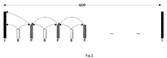
- Figure 1 is an example diagram showing a reference relationship among three frame types.
- an I Frame is firstly decoded, and then related P and B Frames are decoded in order to play and/or display corresponding frame data.
- the I Frame, and the P Frames and the B Frames in the reference relationship with the I Frame are known jointly as a picture group or a group of pictures (GOP for short).
- random access to a picture frame in the coding stream can be realized.
- it may be needed to firstly locate the I Frame in the GOP to which a target frame belongs, and then decode in sequence all the I Frames, the P Frames and the B Frames before the target frame.
- the decoding process may encounter an excessive number of the coding frames to be decoded, which may result in relatively high resource consumption for decoding and low efficiency during random access.
- Especially embodiments of the present disclosure provides an modified coding method which can produce an modified coding stream including I Frames, Refreshment P Frames and common P Frames to reduce code rate and the consume of decoding.
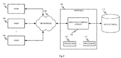
- FIG. 2 is an example computer-implemented environment wherein users 102 can interact with a video-play-control system 104 hosted on one or more servers 106 through a network 108, according to one embodiment of the present invention.
- the users 102 can interact with the video-play-control system 104 through a number of ways, such as over one or more networks 108.
- One or more servers 106 accessible through the network(s) 108 can host the video-play-control system 104.
- the one or more servers 106 can also contain or have access to one or more data stores 110 for storing data for the video-play-control system 104..
- the one or more servers 106 implement one or more data processors 112.
- the one or more servers 106 implement one or more data processors 112.
- the data processors 112 can be configured for parallel computing.
- the video-play-control system 104 can assist the users 102 to improve video encoding to reduce bit rates and decoding consumption.
- the video-play-control system 104 can implement an encoding algorithm to generate a coding stream that includes various types of coding frames, such as I Frames, refreshment P Frames and common P Frames.
- the video-play-control system 104 can reduce decoding resource consumption and achieve fast random access of coding frames, thereby improving decoding efficiency and maintaining smooth play of coding frames without stagnation.
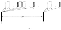
- Figure 3 is an example diagram showing a reference relationship among different types of frames in a video coding stream, according to one embodiment of the present invention and/or disclosure. As shown in Figure 3 , three types of coding frames and GOPs of the coding stream are described as follows:
- I Frame an independent frame with picture data.
- An I Frame can be decoded independently by using an intra-frame prediction encoding algorithm in an encoding process, and the decoding process of the I Frame is independent of other pictures.
- an I Frame is an independent frame with all picture data kept by intra-frame prediction encoding.
- An I Frame can be decoded independently without relying on other frames, and the decoding process of the I Frame is independent of other fames of pictures.
- a Refreshment P Frame is a forward prediction reference frame.
- a forward intra-frame prediction encoding algorithm is employed and/or applied in the encoding process.
- a reference frame of a refreshment P Frame is a preceding I Frame closest to the refreshment P Frame. Since intra-frame prediction of the refreshment P Frame refers to the I Frame rather than the preceding P Frame, quick search and quick decoding may be achieved during random access or video playback, and the decoding wait time is shortened.
- a Common P Frame is a forward prediction reference frame.
- a forward intra-frame prediction encoding algorithm is employed in the encoding process.
- a reference frame of the common P Frame is a preceding coding frame adjacent to the common P Frame, and/or a preceding I Frame closest to the common P Frame.
- the video coding stream includes a plurality of GOPs.
- Each GOP comprises and/or includes a plurality of coding frames having reference relationship.
- a GOP may include an I Frame and one or more following refreshment P Frames and one or more following common P Frames in direct or indirect reference relationship with the I Frame, as shown in Figure 3 .
- the I Frame in the direct or indirect reference relationship with the refreshment P Frames and the common P Frames is called as the reference I Frame.
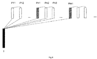
- FIG 4 is an example diagram showing a video coding stream according to one embodiment of the present invention and/or disclosure.
- I refers to an I Frame
- Pn1 and Pm1 refer to refreshment P Frames
- others are common P Frames.
- Fast random access can be realized in the video coding stream. For example, when a common P Frame Pn3 is to be accessed, only the I Frame, Pn1, Pn2 and Pn3 in the same GOP are decoded, especially for location. Other intermediate frames (e.g., the intermediate frames P11, P12, ... before Pn1) are skipped.
- the interval between two I Frames is relatively large. For example, one I Frame may appear every few minutes, thereby reducing the bit rates.
- Refreshment P Frames may appear between the two I Frames at intervals, and are decoded only with reference to the I Frames in the GOP. Common P Frames which are small in data size are distributed between the refreshment P Frames in order to further reduce the bit rates.
- the video coding stream is sent according to the method described herein, or if the coding stream is stored, or if a sending end (e.g., a sending terminal) of the coding stream does not send positioning information to a receiving end (or a decoding end), it is possible to cause great difference between timestamps of the I Frame and the Pn1 frame (a refreshment P Frame). Then the retention time during which the data corresponding to the I Frame is played may become too long to affect user experience and/or then the retention time during the display of the data corresponding to the I Frame may become too long, thus make the video frozen or abnormal to affect user experience.
- Figure 5 is an example flow diagram showing a method for play control and/or display control of a video coding stream according to one embodiment of the present invention and/or disclosure.
- the method 500 can be applied to a video coding stream generated according to the encoding method described herein or a video coding stream generated according to a conventional encoding method.
- a timestamp of an I Frame is Ti
- a timestamp of a refreshment P Frame (e.g., Pn1 as shown in Figure 3 ) is Tpn1.
- the maximum Td can be close to the duration of one GOP, while the duration of the GOP in the coding stream may be several minutes (e.g., the interval between the two I Frames is very long).
- a general-purpose video player plays and/or displays according to the timestamps, and the retention time during playing and/or displaying of the data corresponding to the I Frame (namely playing and/or displaying of the I Frame) is relatively long, so that user experience is directly affected and the user may have the misunderstanding that software crashes or operates abnormally.
- the method 500 includes multiple processes.
- the process S110 includes: extracting a coding frame in a video coding stream.
- the interval between two consecutive I Frames is very large (e.g., as shown in Figures 3 and 4 ).
- the video coding stream can be sent from a sending end (e.g., a sending terminal) to a receiving end (e.g., a receiving terminal) or a decoding end.
- the decoding end can be a general-purpose video player, etc.
- the coding stream sent from the sending end can be received at the receiving end sequentially, such as, the I Frame, the Pn1 frame (a refreshment P Frame), Pn2 frame, Pn3 frame (e.g., as shown in Figure 4 ).
- the process S120 includes: determining whether the coding frame extracted from the received video coding stream is an I Frame.
- the receiving end sequentially receives the coding frames in the coding stream and can extract and detect the coding frames in the coding stream one by one, such as the I Frame, the Pn1 frame (a refreshment P Frame), the Pn2 frame, the Pn3 frame, etc.
- the type of the coding frame or other information can be determined based at least in part on frame information of the I Frame and the Pn1 frame (e.g., the adjacent coding frames after the I Frame when the coding stream is actually stored).
- the frame information of the coding frame includes a tag of the type of the coding frame for determining whether the coding frame is the I Frame.
- Other information may also be used for determining the type of the extracted coding frame, for example, position, serial number, data volume, etc.
- the frame information includes, but is not limited to, timestamp, serial number, relevant tag, display control command, display configuration information, etc.
- a timestamp is a character sequence and can uniquely identify a certain time.
- Each frame of data has the timestamp.
- the serial number is a frame number of the coding frame.
- the relevant tag refers to a tag on an encapsulation layer or an encoding layer for identifying the type of the coding stream or the frame type.
- the display control command refers to positioning information that includes a timestamp of the target frame, the frame number and other information. The positioning information is used for identifying the positioned target information without affecting the timestamp of the coding frame.
- the display configuration information refers to a display control operation which is performed by an application layer on the I Frame.
- the determination process includes a detection process for sequentially acquiring and detecting the coding frames in the incoming coding stream one by one and determining whether each coding frame is the I Frame.
- the process S130 includes: if the coding frame extracted from the received video coding stream is not an I Frame, displaying the extracted coding frame.
- the coding frame extracted in the process S110 is determined to not be the I Frame, then the coding frame can be normally decoded.
- the data (such as picture data, especially of video) corresponding to the coding frame after decoding is displayed by a video player to be watched by the user who requests access to the coding stream.
- the audio data of the video may be synchronously played by a player together with the picture data of the video via a speaker.
- the process S140 includes: if the coding frame extracted from the received video coding stream is an I Frame, performing display control on the I Frame according to the frame information of the extracted I Frame and/or one or more adjacent coding frames after the I Frame.
- the extracted coding frame is determined to be an I Frame in the process S120, then the playing and/or displaying preprocessing can be firstly performed on the I Frame. As an example, whether the data (such as picture data) corresponding to the I Frame needs to be finally displayed is determined.
- whether the I Frame needs to be displayed can be determined (e.g., including determination after certain computation) according the coding stream information of the video coding stream, the frame information of the coding frame of the video coding stream (e.g., including the relevant tag of the coding frame), the configuration condition (e.g., configuration information) and/or the related command in the transmission process, etc.
- the coding stream information of the coding stream comprises frame rate information.
- the coding stream and/or the coding frames in the coding stream comprise and/or include various tags (e.g., relevant tags) set in the encoding layer or the encapsulation layer during encapsulation.
- the coding frames comprise and/or include certain frame information (e.g., timestamps, serial numbers, etc).
- whether to finally display the I Frame can be determined by comparing the difference between the timestamps (e.g., timestamps of the I Frame and the adjacent coding frame after the I Frame) with a preset threshold, comparing the sizes of the timestamps (e.g., timestamps of the I Frame and the adjacent coding frame after the I Frame), determining whether the difference between the timestamps exceeds an error range of allowable difference between the timestamps and acquiring the relevant tag, the related command, etc., for determining whether to display the coding frame.
- the sending end in the transmission process, can also provide the related command, such as the command about whether to play and/or display a related I Frame for each coding frame so as to control the corresponding coding frame to be displayed.
- the configuration information is preset and whether to display the coding frame is provided.
- the receiving end provides the configuration information.
- the coding frame detected or determined to be a first I Frame of the coding stream is not to be displayed.
- other specific I Frames such as the I Frames with odd serial numbers are not to be displayed.
- the coding frame which is detected or determined to be an I Frame and has an odd serial number (e.g., 1,3,5, etc.) in the frame information is not to be displayed.
- Figure 6 is an example flow diagram showing a method for I Frame play control and/or display control of a video coding stream based at least in part on timestamp difference according to one embodiment of the present invention and/or disclosure.
- the video-display-control and/or video-play-control system 104 implements the method 600 to determine whether to play and/or display an I Frame based at least in part on a timestamp of an I Frame and a timestamp of an adjacent coding frame that follows the I Frame.
- the method 600 includes multiple processes.
- the process S210 includes: acquiring a timestamp of an I Frame and a timestamp of an adjacent coding frame after the I Frame.
- the frame information of the I Frame contains the timestamp (e.g., Ti).
- the frame information of the adjacent coding frame after the I Frame e.g., the refresh frame Pn1 contains the timestamp (e.g., Tpn1).
- the threshold can be preset according to a statistical analysis algorithm, user experience, favorability and other demands.
- the difference is compared with the preset threshold, and whether the difference is more than or no less than the threshold is determined.
- the threshold is preset to be 2 seconds, and whether Td is more than or no less than 2 seconds is determined.
- the exceeding of the threshold can be set to be more than or no less than the threshold.
- the process S230 includes: if the difference is determined to exceed the threshold, not displaying the I Frame.
- the process S240 includes: if the difference is determined to not exceed the threshold, displaying the I Frame. Whether to display the I Frame is controlled according to the determination result. For example, if the difference Td is more than or no less than the threshold 2 seconds, then the I Frame is not displayed. If Td does not exceed the threshold (e.g., Td is no more than or less than the threshold 2 seconds), the I Frame is displayed. Thus, before playing and/or displaying an I Frame, whether the I Frame is to be displayed is determined so as to avoid a long retention time during the playing and/or displaying of the I Frame.
- Figure 7 is an example flow diagram showing a method for I Frame play control and/or display control of a video coding stream based at least in part on timestamp difference according to another embodiment of the present invention and/or disclosure.
- the video-display-control and/or video-play-control system 104 implements the method 700 to determine whether to play and/or display an I Frame based at least in part on a timestamp of an I Frame and a timestamp of an adjacent coding frame that follows the I Frame.
- the method 700 includes multiple processes.
- the process S310 includes: acquiring a timestamp of an I Frame and a timestamp of an adjacent coding frame after the I Frame.
- the process S310 is the same as the process 5210.
- the process S320 includes: determining whether the timestamp of the I Frame is larger than the timestamp of the adjacent coding frame after the I Frame.
- the timestamp of the I Frame is compared with the timestamp of the adjacent coding frame after the I Frame to determine whether the timestamp of the I Frame is larger than the timestamp of the adjacent coding frame after the I Frame. As an example, whether Ti of the I Frame is not less than Tpn1 of the adjacent Pn1 frame after the I Frame is determined.
- the process S330 includes: if the timestamp of the I Frame is determined to be larger than the timestamp of the adjacent coding frame after the I Frame, then not displaying the I Frame.
- the process S340 includes: if the timestamp of the I Frame is determined to not exceed the timestamp of the adjacent coding frame after the I Frame, then displaying the I Frame.
- the timestamp of the I Frame is smaller than the timestamps of other coding frames in the GOP that contains the I Frame. For example, if the timestamp of the I Frame is large, it may indicate an abnormality. In another example, if a certain I Frame is not to be displayed, the related timestamp can be modified.
- whether to display the I Frame is controlled according to the determination result. For example, when Ti is not less than Tpn1, the I Frame is not displayed. In another example, when Ti is less than Tpn1, the I Frame is displayed. Thus, before playing and/or displaying an I Frame, whether the I Frame is to be displayed is determined so as to avoid a long retention time during the playing and/or displaying of the I Frame.
- Figure 8 is an example flow diagram showing a method for I Frame play control and/or display control of a video coding stream based at least in part on serial numbers according to an embodiment of the present invention.
- the video-display-control and/or video-play-control system 104 implements the method 800 to determine whether to play and/or display an I Frame based at least in part on a serial number of an I Frame and a serial number of an adjacent coding frame that follows the I Frame.
- the method 800 includes multiple processes.
- the process S410 includes: acquiring a serial number of an I Frame and a serial number of an adjacent coding frame after the I Frame.
- the frame information of each coding frame contains the serial number representing the sequence of the coding frame in the coding stream.
- the frame information of the I Frame contains the serial number.
- the adjacent coding frame after the I Frame in each GOP can be the refreshment P Frame, and the frame information of the refreshment P Frame also contains the serial number of the refreshment P Frame.
- the serial number of the I Frame is 1, which is arranged according to the sequence of actual numbers.
- the adjacent coding frame after the I frame is the refresh frame Pn1, and the serial number can be 2.
- serial numbers of adjacent frames can also be set according to a sequence interval of 10.
- the serial number of the I Frame is 100
- the serial number of the adjacent coding frame after the I Frame namely the refreshment P Frame
- the serial number of the adjacent coding frame after the refreshment P Frame is 120, and so on.
- the serial numbers of the coding frames can be set in different ways as long as the serial numbers are well set when the coding frames are stored. For example, rules for continuous serial numbers can be preset. In the above-noted two examples, the serial numbers 1, 2, 3..., are continuous, and the serial numbers 110, 120, 130..., are also considered continuous.
- the process S420 includes: determining whether the serial number of the I Frame and the serial number of the adjacent coding frame after the I Frame are continuous according to one or more preset rules for continuous serial numbers.
- the I Frame and the acquired coding frame after the I Frame namely the refreshment P Frame
- the serial numbers of the two adjacent frames are continuous under normal circumstances.
- the serial numbers of the adjacent frames can be I Frame: 1, Pn1 frame (a refreshment P Frame): 2, Pn2 frame: 3....
- the process S430 includes: if the serial number of the I Frame and the serial number of the adjacent coding frame after the I Frame are determined to be continuous according to the preset rules, displaying the I Frame.
- the process S440 includes: if the serial number of the I Frame and the serial number of the adjacent coding frame after the I Frame are determined not to be continuous according to the preset rules, not displaying the I Frame.
- the serial number of a current I Frame is 1, and the serial number of the received nearest coding frame after the I Frame is 5. These two frames may not be adjacent frames in the coding stream.
- the nearest coding frame is not a refreshment P Frame in the GOP that contains the I Frame. That is, the nearest coding frame may not be associated with the I Frame.
- the current I Frame may be related to an abnormally long retention, and the I Frame is not to be displayed.
- the serial number of the I Frame is 1, and the serial number of the acquired nearest coding frame after the I Frame is 2.
- the nearest coding frame after the I Frame may be a refreshment P Frame that follows the I Frame (e.g., the Pn1 frame). These two frames are adjacent within a same GOP, and the refreshment P Frame (e.g., the Pn1 frame) follows the I Frame. Thus, the I Frame is displayed.
- Figure 9 is an example flow diagram showing a method for I Frame play control and/or display control of a video coding stream based at least in part on timestamp difference and frame rate information according to an embodiment of the present invention.
- the video-display-control and/or video-play-control system 104 implements the method 900 to determine whether to play and/or display an I Frame based at least in part on timestamps and frame rates of an I Frame and an adjacent coding frame that follows the I Frame.
- the frame rate is a measure for a number of display frames and represents frames per second (referred to as FPS) or "Hertz" (Hz).
- the method 900 includes multiple processes.
- the process S510 includes: acquiring a timestamp of an I Frame and a timestamp of an adjacent coding frame after the I Frame. For example, the process S510 is the same as the process S210. If the frame information of the I Frame contains the timestamp Ti, then the frame information of the adjacent refresh frame Pn1 after the I Frame contains the timestamp Tpn1.
- the process S520 includes: computing a difference between the timestamp of the I Frame and the timestamp of the adjacent coding frame after the I Frame.
- the process S520 is the same as the process S220.
- the process S530 includes: acquiring frame rate information of the video coding stream.
- coding stream information of the video coding stream comprises the frame rate information.
- the process S540 includes: computing an allowable difference between timestamps according to the acquired frame rate information.
- the difference between timestamps of two frames e.g., I Frame and the adjacent coding frame after the I Frame, namely the refresh frame Pn1
- Tf is the allowable difference between the timestamps.
- a fluctuation of ⁇ 10% of the allowable difference between the timestamps can be set on the basis of the allowable difference (e.g., 40 ms) between the timestamps. For example, a range of 36 ms - 44 ms is reasonable.
- the allowable positive and negative errors can be customized by the user.
- the processes S510 and S530 can be executed in any order or simultaneously.
- the process S550 includes: determining whether the difference between the timestamp of the I Frame and the timestamp of the adjacent coding frame after the I Frame is in an error range of the allowable difference. For example, the difference between the timestamps is compared with the allowable difference to determine whether the difference between the timestamps is in the error range of the allowable difference.
- the difference between the timestamps according to the I Frame and the adjacent coding frame after the I Frame is compared with the error range of the allowable difference acquired by computation according to the frame rate information. For example, whether the difference between the timestamps Td is within the error range of Tf can be determined.
- the process S560 includes: if the difference between the timestamps is in the error range of the allowable difference, displaying the I Frame.
- the process S570 includes: if the difference between the timestamps is out of the error range of the allowable difference, not displaying the I Frame. For example, if the difference between the timestamps of the I Frame and the refresh frame Pn1 is in the range of the allowable difference (e.g., 40 ms with an error range of ⁇ 10%), namely Td ⁇ Tf, then the I Frame is displayed.
- the I Frame is not displayed.
- Figure 10 is an example flow diagram showing a method for I Frame play control of a video coding stream based at least in part on relevant tags according to an embodiment of the present invention.
- the video-display-control and/or video-play-control system 104 implements the method 1000 to determine whether to play and/or display an I Frame based at least in part on a relevant tag of an I Frame.
- the method 1000 includes multiple processes.
- the process S610 includes: acquiring a relevant tag of an I Frame in an encapsulation layer or an encoding layer.
- the video coding stream is encapsulated after encoding.
- a relevant tag can be added in the encapsulation layer or the encoding layer for the coding stream or each coding frame in the coding stream.
- the relevant tag includes a display tag which is used for identifying the type of a coding frame or for identifying the certain coding frame as to be displayed/not displayed.
- the process S620 includes: in the encapsulation layer or the encoding layer, if the relevant tag of the I Frame indicates that the I Frame is not to be displayed, then not displaying the I Frame.
- the process S630 includes: if the relevant tag of the I Frame indicates that the I Frame is to be displayed, then displaying the I Frame. For example, if the I Frame has a relevant tag of not being displayed in either the encapsulation layer or the encoding layer, then the I Frame is not to be displayed.
- Figure 11 is an example flow diagram showing a method for I Frame play control and/or display control of a video coding stream based at least in part on commands according to an embodiment of the present invention.
- the video-display-control and/or video-play-control system 104 implements the method 1100 to determine whether to play and/or display an I Frame based at least in part on certain commands.
- a command may be related to a coding frame and is provided by a sending end of the video coding stream in the transmission process, and the command may indicate whether to display the coding frame.
- the method 1100 includes multiple processes.
- the process S710 includes: acquiring a command from a sending end according to frame rate information of the video coding stream. For example, when the sending end sends the coding stream to a receiving end (a decoding end), such as a general-purpose video player, corresponding frame rate information is carried in the coding stream.
- a decoding end such as a general-purpose video player
- the frame rate information includes the command from the sending end for allowing the receiving end to complete reception, storage, decoding, playing and/displaying and other treatments of the coding stream.
- the process S720 includes: acquiring a display control command according to the command from the sending end.
- the command from the sending end includes a display control command for controlling or identifying a certain coding frame to be displayed or not to be displayed.
- the process S730 includes: if the display control command indicates that the I Frame is not to be displayed, then not displaying the I Frame.
- the process S740 includes: if the display control command indicates that the I Frame is to be displayed, then displaying the I Frame.
- the sending end when the sending end sends the video coding stream, the corresponding command from the sending end exists in the frame rate information and a display control command exists in the command from the sending end.
- a display control command exists in the command from the sending end.
- a certain I Frame in the coding stream can be controlled to be displayed or not to be displayed in real-time.
- the sending end in the transmission process of the coding stream, can synchronously send the display control command for the coding stream, and the display control command controls if the I Frame is to be displayed in real-time.
- Figure 12 is an example flow diagram showing a method for I Frame play control and/or display control of a video coding stream based at least in part on configuration information according to an embodiment of the present invention.
- the video-display-control and/or video-play-control system 104 implements the method 1200 to determine whether to play and/or display an I Frame based at least in part on configuration information of an I Frame.
- the method 1200 includes multiple processes.
- the process S810 includes: acquiring display configuration information of an I Frame.
- the display configuration information of the I Frame is preset and used for controlling a first I Frame in the video coding stream or a designated I Frame not to be displayed.
- the process S820 includes: determining whether the I Frame is a first I Frame in the video coding stream or a designated I Frame according to the display configuration information.
- an I Frame is not to be displayed according to the preset display configuration information. For example, before a coding frame extracted from the incoming coding stream is detected or determined to be an I Frame, the display configuration information is preset as follows: the first I Frame in the incoming coding stream is not displayed, or a designated I Frame is not displayed (e.g., the I Frame with an odd serial number in the incoming coding stream is not displayed).
- the display configuration information can be related to frame information and coding stream information (e.g., frame rate information, layer information, etc.).
- whether an I Frame is designated can be determined by comparing the serial number, the timestamp, or other information, in the frame information of the I Frame to one or more designated conditions in the display configuration information.
- the process S830 includes: if the I Frame is the first I Frame in the video coding stream or if the I Frame is designated according to the display configuration information, not displaying the I Frame.
- the process S840 includes: if the I Frame is not the first I Frame in the video coding stream or if the I Frame is not designated according to the display configuration information, then displaying the I Frame.
- certain execution conditions of I Frame display control in the process S140 can be used, singly or in any combination, as the condition for I Frame display.
- difference between timestamps e.g., as shown in Figure 6
- serial numbers e.g., as shown in Figure 7
- the conditions for determining whether to display an I Frame can be combined as the conditions for determining whether to display an I Frame. As an example, whether the serial numbers are continuous is determined. If the serial numbers are continuous, then whether the difference between the timestamps is below a threshold is determined. If the difference between the timestamps exceeds the threshold, the I Frame is not to be displayed even if the serial numbers are continuous. As another example, if the serial numbers are not continuous, the I Frame cannot be displayed.
- Figure 13 is an example diagram for a system for video play control and/or display control according to one embodiment of the present invention.
- the system 1300 comprises and/or includes an extraction device 111, a determination device 120, a display device 130 and a display control device 140.
- the extraction device 111 is configured to extract a coding frame in a video coding stream.
- the extraction device 111 implements the process S110.
- the determination device 120 is connected with the extraction device 111, and configured to determine whether the extracted coding frame is an I Frame. As an example, the determination device 120 implements the process S120.
- the display device 130 is connected with the determination device 120, and configured to display the extracted coding frame if the extracted coding frame is not an I Frame.
- the display device 130 implements the process S130.
- the display control device 140 is connected with the determination device 120, and configured to, if the coding frame extracted from the received video coding stream is an I Frame, perform display control on the I Frame according to the frame information of the extracted I Frame and/or one or more adjacent coding frames after the I Frame.
- the display control device 140 implements the process S140.
- the display control device 140 implements certain display control algorithms or certain display control conditions related to the process S140 as shown in Figures 6-12 .
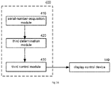
- Figures 14-20 are example diagrams for the display control device 140 according to some embodiments of the present invention.
- the described display control device 140 comprises and/or includes: a first timestamp device 200, a second timestamp device 300, a serial-number device 400, a frame-rate-and-timestamp device 500, a relevant-tag device 600, a display-control-command device 700 and a display-configuration-information device 800.
- the first timestamp device 200 implements the method 600.
- the first timestamp device 200 comprises and/or includes: an acquisition module 210 configured to acquire the timestamp of the I Frame and the timestamp of the adjacent coding frame after the I Frame.
- the acquisition module 210 implements the process S210.
- the first determination module 220 implements the process S220.
- the first timestamp device 200 comprises and/or includes: a first control module 230 configured to not display the I Frame if the determination result of the first determination module 220 is that the difference between the timestamps exceeds the threshold; and display the I Frame if the determination result of the first determination module 220 is that the difference between the timestamps does not exceed the threshold.
- the first control module 230 implements the process S230 and the process S240.
- the second timestamp device 300 implements the method 700.
- the second timestamp device 300 comprises and/or includes: a second determination module 320 connected with the acquisition module 210 and configured to determine whether the timestamp of the I Frame acquired by the acquisition module 210 is larger than the timestamp of the adjacent coding frame after the I Frame.
- the second determination module 320 implements the process S320.
- the second timestamp device 300 comprises and/or includes: a second control module 330 configured not to display the I Frame if the determination result of the second determination module 320 is that the timestamp of the I Frame exceeds the timestamp of the adjacent coding frame after the I Frame; and display the I Frame if the determination result of the second determination module 320 is that the timestamp of the I Frame does not exceed the timestamp of the adjacent coding frame after the I Frame.
- the second control module 330 implements the process S330 and the process S340.
- the serial-number device 400 implements the method 800.
- the serial-number device 400 comprises and/or includes: a serial-number-acquisition module 410 configured to acquire the serial number of the I Frame and the serial number of the adjacent coding frame after the I Frame.
- the serial-number-acquisition module 410 implements the process S410.
- the serial-number device 400 comprises and/or includes: a third determination module 420 configured to determine whether the serial number of the I Frame and the serial number of the adjacent coding frame after the I Frame are continuous according to the preset rules for continuous serial numbers.
- the third determination module 420 implements the process S420.
- the serial-number device 400 comprises and/or includes: a third control module 430 configured not to display the I Frame if the determination result of the third determination module 420 is that the serial number of the I Frame and the serial number of the adjacent coding frame after the I Frame are not continuous; and display the I Frame if the determination result of the third determination module 420 is that the serial numbers are continuous.
- the third control module 430 implements the process S430 and the process S440.
- the frame-rate-and-timestamp device 500 implements the method 900.
- the frame-rate-and-timestamp device 500 comprises and/or includes: a timestamp-difference-computation module 520 connected with the acquisition module 210 and configured to compute the difference between the timestamp of the I Frame and the timestamp of the adjacent coding frame after the I Frame.
- the timestamp-difference-computation module 520 implements the process S520.
- the frame-rate-and-timestamp device 500 comprises and/or includes: a frame-rate-information-acquisition module 530 configured to acquire the frame rate information of the video coding stream.
- the frame-rate-information-acquisition module 530 implements the process S530.
- the frame-rate-and-timestamp device 500 comprises: an allowable-value-computation module 540 configured to compute an allowable difference between the timestamps according to the acquired frame rate information.
- the allowable-value-computation module 540 implements the process S540.
- the frame-rate-and-timestamp device 500 comprises and/or includes: a fourth determination module 550 configured to determine whether the difference between the timestamps is in the error range of the allowable difference between the timestamps.
- the fourth determination module 550 implements the process S550.
- the frame-rate-and-timestamp device 500 comprises and/or includes: a fourth control module 560 configured to display the I Frame if the difference between the timestamps is in the error range of the allowable difference between the timestamps, and not to display the I Frame if the difference is out of the error range of the allowable difference between the timestamps.
- the fourth control module 560 implements the process S560 and the process S570.
- the relevant-tag device 600 implements the method 1000.
- the relevant-tag device 600 comprises and/or includes: a relevant-tag-acquisition module 610 configured to acquire the relevant tag of the I Frame in an encapsulation layer or an encoding layer.
- the relevant-tag-acquisition module 610 implements the process S610.
- the relevant-tag device 600 comprises and/or includes: a fifth control module 620 configured not to display the I Frame if the relevant tag of the I Frame in the encapsulation layer or the encoding layer indicates that the I Frame is to be displayed, and display the I Frame if the relevant tag of the I Frame indicates that the I Frame is to be displayed.
- the fifth control module 620 implements the process S620 and the process S630.
- the display-control-command device 700 implements the method 1100.
- the display-control-command device 700 comprises and/or includes: a sending-end-command-acquisition module 710 configured to acquire a command from the sending end according to frame rate information of the video coding stream.
- the sending-end-command-acquisition module 710 implements the process S710.
- the display-control-command device 700 comprises and/or includes: a display-control-command-analysis module 720 configured to acquire a display control command according to the command from the sending end.
- the display-control-command-analysis module 720 implements the process S720.
- the display-control-command device 700 comprises and/or includes: a sixth control module 730 configured to, if the display control command indicates that the I Frame is not to be displayed, not display the I Frame; and if the display control command indicates that the I Frame is to be displayed, display the I Frame.
- the sixth control module 730 implements the process S730 and the process S740.
- the display-configuration-information device 800 implements the method 1200.
- the display-configuration-information device 800 comprises and/or includes: a display-configuration-information-acquisition module 810 configured to acquire display configuration information of an I Frame.
- the display-configuration-information-acquisition module 810 implements the process S810.
- the display-configuration-information device 800 comprises and/or includes: a seventh determination module 820 configured to determine whether the I Frame is the first I Frame in the video coding stream or the designated I Frame according to the display configuration information.
- the seventh determination module 820 implements the process S820.
- the display-configuration-information device 800 comprises and/or includes: a seventh control module 830 configured to, if the I Frame is the first I Frame in the video coding stream or if the I Frame is designated according to the display configuration information, not display the I Frame; and if the I Frame is not the first I Frame in the video coding stream or if the I Frame is not designated according to the display configuration information, display the I Frame.
- the seventh control module 830 implements the process S830 and the process S840.
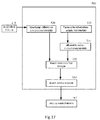
- FIG 21 is an example diagram for a system for video play control and/or display control according to one embodiment of the present invention.
- the system 1700 includes a computing system 1712 which contains a processor 1714, a storage device 1716 and a video-display-control and/or video-play-control module 1718.
- the computing system 1712 includes any suitable type of computing device (e.g., a server, a desktop, a laptop, a tablet, a mobile phone, etc.) that includes the processor 1714 or provide access to a processor via a network or as part of a cloud based application.
- the video-display-control and/or video-play-control module 1718 includes tasks and is implemented as part of a user interface module (not shown in Figure 21 ).
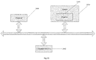
- Figure 22 is an example diagram showing a computing system for video play control and/or display control.
- the computing system 1612 includes a processor 1614, memory devices 1702 and 1704, one or more input/output devices 1706, one or more networking components 1708, and a system bus 1710.
- the computing system 1612 includes the video-display-control and/or video-play-control module 1718, and provides access to the video-play-control module 1718 to a user as a stand-alone computer.
- a method for video play control and/or display control includes: determining whether a coding frame extracted from a video coding stream is an I Frame; and in response to the coding frame extracted from the video coding stream being determined as an I Frame, performing display control on the I Frame based at least in part on frame information of the extracted I Frame and one or more adjacent coding frames after the I Frame.
- a system for video play control and/or display control includes: an extraction device configured to extract a coding frame in a video coding stream; a determination device configured to determine whether the extracted coding frame is an I Frame; and a display control device configured to, in response to the coding frame extracted from the video coding stream being determined as an I Frame, perform display control on the I Frame based at least in part on frame information of the extracted I Frame and one or more adjacent coding frames after the I Frame.
- a system for video play control and/or display control includes: one or more data processors; and one or more non-transitory computer-readable storage media encoded with instructions for commanding the data processors to execute certain operations.
- the operations include: determining whether a coding frame extracted from a video coding stream is an I Frame; and in response to the coding frame extracted from the video coding stream being determined as an I Frame, performing display control on the I Frame based at least in part on frame information of the extracted I Frame and one or more adjacent coding frames after the I Frame.
- Especially the operations include: determining whether a coding frame extracted from a video coding stream is an I Frame; and if the coding frame extracted from the video coding stream is determined as an I Frame, performing display control on the I Frame based at least in part on frame information of the extracted I Frame and one or more adjacent coding frames after the I Frame.
- a non-transitory computer-readable storage medium is encoded with instructions for commanding one or more processors to execute a method for video display control.
- the method includes: determining whether a coding frame extracted from a video coding stream is an I Frame; and if the coding frame extracted from the video coding stream is determined as an I Frame, performing display control on the I Frame based at least in part on frame information of the extracted I Frame and one or more adjacent coding frames after the I Frame.
- a non-transitory computer-readable storage medium is encoded with instructions for commanding one or more processors to execute a method for video play control.
- the method comprises: determining whether a coding frame extracted from a video coding stream is an I Frame; and in response to the coding frame extracted from the video coding stream being determined as an I Frame, performing display control on the I Frame based at least in part on frame information of the extracted I Frame and one or more adjacent coding frames after the I Frame.
- a system for video display control which includes: processor 2001, Communication Interface 2002, memory 2003 and Communication Bus 2004.
- processor 2001, Communication Interface 2001, and memory 2003 communicate with each other through Communication Bus 2004.
- processor 2001 is configured to execute program 2005.
- program 2005 includes program codes, wherein the program codes include program instructions.
- processor 2001 is a Central Processing Unit (CPU), or Application Specific Integrated Circuit (ASIC), or configured to one or more integrated circuits implementing the embodiments of the present disclosure.
- CPU Central Processing Unit
- ASIC Application Specific Integrated Circuit
- memory 2003 is configured to store program 2005.
- memory 2003 includes high-speed RAM.
- memory 2003 further includes non-volatile memory.
- memory 2003 includes at least one magnetic disk memory.
- program 2005 is configured to execute the procedures including: determining whether a coding frame extracted from the video coding stream is an I Frame; if the coding frame extracted from the video coding stream is an I Frame, acquiring a timestamp of the I Frame and a timestamp of an adjacent coding frame after the I Frame; and controlling display of the I Frame based on the timestamp of the I Frame and the timestamp of the adjacent coding frame after the I Frame.
- procedures of program 2005 may be implemented as described in one or more embodiments above.
- the processor may be configured to execute the program to implement:
- the processor may be configured to execute the program to implement:
- the processor may be configured to execute the program to implement:
- the processor may be configured to execute the program to implement:
- the processor may be configured to execute the program to implement:
- the processor may be configured to execute the program to implement:
- the video code stream may include one or more picture groups; and each picture group may include one I Frame, Refreshment P Frames and common P Frames; wherein the Refreshment P Frames and the common P Frames are after the I Frame and directly or indirectly refer to the I Frame; and wherein the adjacent coding frame after the I Frame within a same picture group is stored as a Refreshment P Frame when the video code stream is stored.
- the processor may be configured to execute the program to implement:
- the data (such as a video figure) corresponding to the I frame is detected before it is displayed, to obtain the information of the I frame and the coding frame(s) after the I frame, and then determine quickly whether to display the data corresponding to the I frame or not based on the obtained information, so as to avoid the abnormal long time stay during the display of the decoded data of the I frame.
- the embodiments of the present disclosure may be applied to the display of both the modified coding streams (such as the coding streams in the embodiments of Figs.2-23 ) and the display of the traditional coding streams (such as the coding streams in the embodiment of Fig.1 ).
- some or all components of various embodiments of the present invention and/or disclosure each are, individually and/or in combination with at least another component, implemented using one or more software components, one or more hardware components, and/or one or more combinations of software and hardware components.
- some or all components of various embodiments of the present invention and/or disclosure each are, individually and/or in combination with at least another component, implemented in one or more circuits, such as one or more analog circuits and/or one or more digital circuits.
- various embodiments and/or examples of the present invention and/or disclosure can be combined.
- the methods and systems described herein may be implemented on many different types of processing devices by program code comprising program instructions that are executable by the device processing subsystem.
- the software program instructions may include source code, object code, machine code, or any other stored data that is operable to cause a processing system to perform the methods and operations described herein.
- Other implementations may also be used, however, such as firmware or even appropriately designed hardware configured to perform the methods and systems described herein.
- the systems' and methods' data may be stored and implemented in one or more different types of computer-implemented data stores, such as different types of storage devices and programming constructs (e.g., RAM, ROM, EEPROM, Flash memory, flat files, databases, programming data structures, programming variables, IF-THEN (or similar type) statement constructs, application programming interface, etc.).
- storage devices and programming constructs e.g., RAM, ROM, EEPROM, Flash memory, flat files, databases, programming data structures, programming variables, IF-THEN (or similar type) statement constructs, application programming interface, etc.
- data structures describe formats for use in organizing and storing data in databases, programs, memory, or other computer-readable media for use by a computer program.
- the systems and methods may be provided on many different types of computer-readable media including computer storage mechanisms (e.g., CD-ROM, diskette, RAM, flash memory, computer's hard drive, DVD, etc.) that contain instructions (e.g., software) for use in execution by a processor to perform the methods' operations and implement the systems described herein.
- computer storage mechanisms e.g., CD-ROM, diskette, RAM, flash memory, computer's hard drive, DVD, etc.
- instructions e.g., software
- the computer components, software modules, functions, data stores and data structures described herein may be connected directly or indirectly to each other in order to allow the flow of data needed for their operations.
- a module or processor includes a unit of code that performs a software operation, and can be implemented for example as a subroutine unit of code, or as a software function unit of code, or as an object (as in an object-oriented paradigm), or as an applet, or in a computer script language, or as another type of computer code.
- the software components and/or functionality may be located on a single computer or distributed across multiple computers depending upon the situation at hand.
- the computing system can include client devices and servers.
- a client device and server are generally remote from each other and typically interact through a communication network.
- the relationship of client device and server arises by virtue of computer programs running on the respective computers and having a client device-server relationship to each other.
Abstract
Description
- This application claims priority to Chinese Patent Application No.
201510131031.5, filed on March 25, 2015 - Video encoding is a process of encoding dynamic pictures and digitizing analog picture signals. The video encoding process can implement picture frequency band compression, and reduce or eliminate redundancy of information in digital pictures, so as to enable the capacity of a transmission channel of a video to be smaller than that of a channel during analog transmission and/or to enable the channel capacity for transmission of a video to be smaller than the channel capacity for analog transmission.
- The video encoding is generally and/or usually implemented by a video encoder. As for a traditional video encoder, coding frames are generally divided into three types: I Frames, P Frames and B Frames and/or traditional video encoder generally divides coding frames into three types: I Frames, P Frames and B Frames
- Generally, at a video receiving end, for a received video coding stream, a video player is used for displaying objects corresponding to certain video data obtained from decoding of the coding frames. For example, a general-purpose player is utilized for playing video pictures and the like corresponding to the coding frames of the coding stream. The general-purpose player refers to player application software which is popular in the market or is widely used, such as VLC multimedia player (referred to as VLC, Visible Light Communication), Storm Codec, Microsoft's media player, etc. Video players usually play the data corresponding to the coding frames according to timestamps.
- In other words usually, after a video coding stream is received at a video receiving end, a video player will be used to decoding the coding frames of the video coding stream to obtain relevant data, and then display the objects corresponding to the relevant data, for example, a universal player is used for displaying video pictures corresponding to the coding frames of the video coding stream. A universal player refers to the player application software which is popular in the market or is widely used, such as Visible Light Communication (VLC) multimedia player, Storm Codec, Microsoft's media player, etc..
- Conventionally, the decoding process of the traditional encoder is as follows: firstly decoding the I Frames and then successively decoding in sequence. When the number of the coding frames is relatively large and particularly the P Frames and the B Frames need to refer to other frames, the decoding process may encounter an excessive number of the coding frames to be decoded, which may result in relatively high resource consumption for decoding and low efficiency during random access and/or may result in relatively high resource consumption and low efficiency for decoding during random access.
- Hence it is highly desirable to improve the techniques for play control of video coding streams and/or the techniques for controlling the display of video coding streams.
- According to one embodiment, a method for video play control. An example method includes: determining whether a coding frame extracted from a video coding stream is an I Frame; and in response to the coding frame extracted from the video coding stream being determined as an I Frame, performing display control on the I Frame based at least in part on frame information of the extracted I Frame and one or more adjacent coding frames after the I Frame.
- In another aspect, an embodiment of the present disclosure provides a method for controlling video display, which includes: determining, by one or more processors, whether a coding frame extracted from a video coding stream is an I Frame; if the coding frame extracted from the video coding stream is an I Frame, acquiring, by the one or more processors, a timestamp of the I Frame and a timestamp of an adjacent coding frame after the I Frame; and controlling, by the one or more processors, display of the I Frame based on the timestamp of the I Frame and the timestamp of the adjacent coding frame after the I Frame.
- According to another embodiment, a system for video play control includes: an extraction device configured to extract a coding frame in a video coding stream; a determination device configured to determine whether the extracted coding frame is an I Frame; and a display control device configured to, in response to the coding frame extracted from the video coding stream being determined as an I Frame, perform display control on the I Frame based at least in part on frame information of the extracted I Frame and one or more adjacent coding frames after the I Frame.
- In another aspect, another embodiment of the present disclosure provides a method for controlling video display, which includes: determining whether a coding frame extracted from the video coding stream is an I Frame; if the coding frame is an I Frame, acquiring a serial number of the I Frame and a serial number of an adjacent coding frame after the I Frame; determining whether the serial number of the I Frame and the serial number of the adjacent coding frame after the I Frame are continuous; if the serial number of the I Frame and the serial number of the adjacent coding frame after the I Frame is continuous, displaying the I Frame; and if the serial number of the I Frame and the serial number of the adjacent coding frame after the I Frame is not continuous, not displaying the I Frame.
- In another aspect, another embodiment of the present disclosure provides a system for controlling video display, which includes: an extraction device configured to extract a coding frame from a video coding stream; a determination device configured to determine whether the extracted coding frame is an I Frame; and a display control device configured to, perform display control on the I Frame based on the timestamp of the I Frame and the timestamp of the adjacent coding frame after the I Frame, if the coding frame extracted from the video coding stream being determined as an I Frame.
- According to yet another embodiment, a system for video play control includes: one or more data processors; and one or more non-transitory computer-readable storage media encoded with instructions for commanding the data processors to execute certain operations. The operations include: determining whether a coding frame extracted from a video coding stream is an I Frame; and in response to the coding frame extracted from the video coding stream being determined as an I Frame, performing display control on the I Frame based at least in part on frame information of the extracted I Frame and one or more adjacent coding frames after the I Frame.
- In another aspect, another embodiment of the present disclosure provides a system for controlling video display, which includes: a processor, a communication interface, a memory and a communication bus, wherein the processor, the communication interface and the memory communicate with each other through the communicate bus; the memory is configured to store a program, and the processor is configured to execute the program to implement: determining whether a coding frame extracted from a video coding stream is an I Frame; if the coding frame extracted from the video coding stream is an I Frame, acquiring a timestamp of the I Frame and a timestamp of an adjacent coding frame after the I Frame; and controlling display of the I Frame based on the timestamp of the I Frame and the timestamp of the adjacent coding frame after the I Frame.
- According to yet another embodiment, a non-transitory computer-readable storage medium is encoded with instructions for commanding one or more processors to execute a method for video play control. The method comprises: determining whether a coding frame extracted from a video coding stream is an I Frame; and in response to the coding frame extracted from the video coding stream being determined as an I Frame, performing display control on the I Frame based at least in part on frame information of the extracted I Frame and one or more adjacent coding frames after the I Frame.
- Depending upon embodiment and/or embodiments of the present disclosure, one or more benefits may be achieved. These benefits and various additional objects, features and advantages of the present invention and/or disclosure can be fully appreciated with reference to the detailed description and accompanying drawings that follow.
-
-
Figure 1 is an example diagram showing a reference relationship among three frame types. -
Figure 2 is an example computer-implemented environment wherein users can interact with a video-play-control system and/or video-display-control system hosted on one or more servers through a network, according to one embodiment of the present invention and/or disclosure. -
Figure 3 is an example diagram showing a reference relationship among different types of frames in a video coding stream, according to one embodiment of the present invention and/or disclosure. -
Figure 4 is an example diagram showing a video coding stream according to one embodiment of the present invention and/or disclosure. -
Figure 5 is an example flow diagram showing a method for play control and/or display control of a video coding stream according to one embodiment of the present invention and/or disclosure. -
Figure 6 is an example flow diagram showing a method for I Frame play control and/or display control of a video coding stream based at least in part on timestamp difference according to one embodiment of the present invention and/or disclosure. -
Figure 7 is an example flow diagram showing a method for I Frame play control and/or display control of a video coding stream based at least in part on timestamp difference according to another embodiment of the present invention and/or disclosure. -
Figure 8 is an example flow diagram showing a method for I Frame play control and/or display control of a video coding stream based at least in part on serial numbers according to an embodiment of the present invention and/or disclosure. -
Figure 9 is an example flow diagram showing a method for I Frame play control and/or display control of a video coding stream based at least in part on timestamp difference and frame rate information according to an embodiment of the present invention and/or disclosure. -
Figure 10 is an example flow diagram showing a method for I Frame play control and/or display control of a video coding stream based at least in part on relevant tags according to an embodiment of the present invention and/or disclosure. -
Figure 11 is an example flow diagram showing a method for I Frame play control and/or display control of a video coding stream based at least in part on commands according to an embodiment of the present invention and/or disclosure. -
Figure 12 is an example flow diagram showing a method for I Frame play control and/or display control of a video coding stream based at least in part on configuration information according to an embodiment of the present invention and/or disclosure. -
Figure 13 is an example diagram for a system for video play control and/or display control according to one embodiment of the present invention and/or disclosure. -
Figures 14-20 are example diagrams for adisplay control device 140 as part of the video-play-control system and/or video-display-control system as shown inFigure 13 according to some embodiments of the present invention and/or disclosure. -
Figure 21 is an example diagram for a system for video play control and/or video display control according to one embodiment of the present invention and/or disclosure. -
Figure 22 is an example diagram showing a computing system for video play control and/or video display control. -
Figure 23 is an example diagram showing a computing system for video display control. - Preferably embodiments of the present disclosure provides a method and system for controlling video display to avoid the residence time of the display of the I frame being too long when the video coding stream is displayed by a universal player, to solve the problem of abnormal time stay during the display of the decoded data of the I frame.
- I Frames correspond to one frame type specified by video encoding and decoding standard. Each I Frame adopts an intra-frame prediction encoding method. An I Frame can completely retain data of one picture frame and is an independent frame with all the data of the picture. When the I Frame is decoded, one picture frame can be acquired by independently decoding the I Frame, and the decoding process does not depend on other frames. That is, the complete picture can be acquired by decoding the I Frame only without referring to other frames.
- In other words I Frame represents one frame type specified by video encoding and decoding standard. Each I Frame adopts an intra-frame prediction encoding method to preserve completely data of one frame of picture, and one I Frame is an independent frame with all the data of the picture. When the I Frame is decoded, one picture frame can be acquired by independently decoding the I Frame, and the decoding process does not rely on other frames, that is, the complete picture may be acquired by decoding the I Frame only without referring to other frames.
- P Frames are forward prediction frames. Each P Frame does not contain the complete data of a picture, but has the difference between the present frame and the previous I Frame or P Frame and/or haseach P Frame contains the difference between the present frame and the previous I Frame or P Frame. When the P Frame is decoded, the previous P Frame or I Frame can be taken as reference to superimpose the previous I Frame or P Frame with the present frame to generate a final picture.
- B Frames are bidirectional differential frames (bidirectional prediction frames). Each B Frame records the difference between the present frame and the previous frame and the next frame. When the B Frame is decoded, not only the picture before decoding, but also the picture after decoding may need to be acquired. Namely, both the previous frame and the next frame are taken as references to superimpose the differential data between the previous picture and the next picture and the present frame, and then the final picture can be acquired. Both the P Frame and the B Frame refer, especially need to refer, to other frames and have dependent relation with other frames. A complete picture cannot be acquired by decoding the P Frames or the B Frames only.
-
Figure 1 is an example diagram showing a reference relationship among three frame types. According to the reference relationship of the coding frames inFigure 1 , when a coding stream is played and/or displayed, an I Frame is firstly decoded, and then related P and B Frames are decoded in order to play and/or display corresponding frame data. Generally, the I Frame, and the P Frames and the B Frames in the reference relationship with the I Frame are known jointly as a picture group or a group of pictures (GOP for short). - For the video coding stream after encoding, random access to a picture frame in the coding stream can be realized. In order to realize random access, it may be needed to firstly locate the I Frame in the GOP to which a target frame belongs, and then decode in sequence all the I Frames, the P Frames and the B Frames before the target frame. When the number of the coding frames is relatively large and particularly the P Frames and the B Frames need to refer to other frames, the decoding process may encounter an excessive number of the coding frames to be decoded, which may result in relatively high resource consumption for decoding and low efficiency during random access.
- Especially embodiments of the present disclosure provides an modified coding method which can produce an modified coding stream including I Frames, Refreshment P Frames and common P Frames to reduce code rate and the consume of decoding.
-
Figure 2 is an example computer-implemented environment whereinusers 102 can interact with a video-play-control system 104 hosted on one or more servers 106 through anetwork 108, according to one embodiment of the present invention. As shown inFigure 2 , theusers 102 can interact with the video-play-control system 104 through a number of ways, such as over one ormore networks 108. One or more servers 106 accessible through the network(s) 108 can host the video-play-control system 104. The one or more servers 106 can also contain or have access to one ormore data stores 110 for storing data for the video-play-control system 104.. Preferably the one or more servers 106 implement one ormore data processors 112. The one or more servers 106 implement one ormore data processors 112. For example, thedata processors 112 can be configured for parallel computing. - The video-play-
control system 104 can assist theusers 102 to improve video encoding to reduce bit rates and decoding consumption. As an example, the video-play-control system 104 can implement an encoding algorithm to generate a coding stream that includes various types of coding frames, such as I Frames, refreshment P Frames and common P Frames. For example, the video-play-control system 104 can reduce decoding resource consumption and achieve fast random access of coding frames, thereby improving decoding efficiency and maintaining smooth play of coding frames without stagnation. -
Figure 3 is an example diagram showing a reference relationship among different types of frames in a video coding stream, according to one embodiment of the present invention and/or disclosure. As shown inFigure 3 , three types of coding frames and GOPs of the coding stream are described as follows: - I Frame: an independent frame with picture data. An I Frame can be decoded independently by using an intra-frame prediction encoding algorithm in an encoding process, and the decoding process of the I Frame is independent of other pictures.
- In other words in one embodiment, an I Frame is an independent frame with all picture data kept by intra-frame prediction encoding. An I Frame can be decoded independently without relying on other frames, and the decoding process of the I Frame is independent of other fames of pictures.
- Especially in one embodiment a Refreshment P Frame is a forward prediction reference frame. A forward intra-frame prediction encoding algorithm is employed and/or applied in the encoding process. A reference frame of a refreshment P Frame is a preceding I Frame closest to the refreshment P Frame. Since intra-frame prediction of the refreshment P Frame refers to the I Frame rather than the preceding P Frame, quick search and quick decoding may be achieved during random access or video playback, and the decoding wait time is shortened.
- Especially in one embodiment, a Common P Frame is a forward prediction reference frame. A forward intra-frame prediction encoding algorithm is employed in the encoding process. A reference frame of the common P Frame is a preceding coding frame adjacent to the common P Frame, and/or a preceding I Frame closest to the common P Frame.
- The video coding stream includes a plurality of GOPs. Each GOP comprises and/or includes a plurality of coding frames having reference relationship. A GOP may include an I Frame and one or more following refreshment P Frames and one or more following common P Frames in direct or indirect reference relationship with the I Frame, as shown in
Figure 3 . In the GOP, the I Frame in the direct or indirect reference relationship with the refreshment P Frames and the common P Frames is called as the reference I Frame. -
Figure 4 is an example diagram showing a video coding stream according to one embodiment of the present invention and/or disclosure. As shown inFigure 4 , I refers to an I Frame, Pn1 and Pm1 refer to refreshment P Frames, and others are common P Frames. Fast random access can be realized in the video coding stream. For example, when a common P Frame Pn3 is to be accessed, only the I Frame, Pn1, Pn2 and Pn3 in the same GOP are decoded, especially for location. Other intermediate frames (e.g., the intermediate frames P11, P12, ... before Pn1) are skipped. - As shown in
Figure 3 , the interval between two I Frames is relatively large. For example, one I Frame may appear every few minutes, thereby reducing the bit rates. Refreshment P Frames may appear between the two I Frames at intervals, and are decoded only with reference to the I Frames in the GOP. Common P Frames which are small in data size are distributed between the refreshment P Frames in order to further reduce the bit rates. - In some circumstances, if the video coding stream is sent according to the method described herein, or if the coding stream is stored, or if a sending end (e.g., a sending terminal) of the coding stream does not send positioning information to a receiving end (or a decoding end), it is possible to cause great difference between timestamps of the I Frame and the Pn1 frame (a refreshment P Frame). Then the retention time during which the data corresponding to the I Frame is played may become too long to affect user experience and/or then the retention time during the display of the data corresponding to the I Frame may become too long, thus make the video frozen or abnormal to affect user experience.
-
Figure 5 is an example flow diagram showing a method for play control and/or display control of a video coding stream according to one embodiment of the present invention and/or disclosure. For example, themethod 500 can be applied to a video coding stream generated according to the encoding method described herein or a video coding stream generated according to a conventional encoding method. - In a coding stream generated using the video encoding method described herein, a timestamp of an I Frame is Ti, and a timestamp of a refreshment P Frame (e.g., Pn1 as shown in
Figure 3 ) is Tpn1. Then the difference between the timestamps is Td=Tpn1-Ti. Theoretically, the maximum Td can be close to the duration of one GOP, while the duration of the GOP in the coding stream may be several minutes (e.g., the interval between the two I Frames is very long). Under normal circumstances, a general-purpose video player plays and/or displays according to the timestamps, and the retention time during playing and/or displaying of the data corresponding to the I Frame (namely playing and/or displaying of the I Frame) is relatively long, so that user experience is directly affected and the user may have the misunderstanding that software crashes or operates abnormally. - As shown in
Figure 5 , themethod 500 includes multiple processes. For example, the process S110 includes: extracting a coding frame in a video coding stream. In one embodiment, in the video coding stream (e.g., as shown inFigure 4 ), the interval between two consecutive I Frames is very large (e.g., as shown inFigures 3 and4 ). In certain embodiments, the video coding stream can be sent from a sending end (e.g., a sending terminal) to a receiving end (e.g., a receiving terminal) or a decoding end. For example, the decoding end can be a general-purpose video player, etc. For example, the coding stream sent from the sending end can be received at the receiving end sequentially, such as, the I Frame, the Pn1 frame (a refreshment P Frame), Pn2 frame, Pn3 frame (e.g., as shown inFigure 4 ). - The process S120 includes: determining whether the coding frame extracted from the received video coding stream is an I Frame. In one embodiment, the receiving end sequentially receives the coding frames in the coding stream and can extract and detect the coding frames in the coding stream one by one, such as the I Frame, the Pn1 frame (a refreshment P Frame), the Pn2 frame, the Pn3 frame, etc. The type of the coding frame or other information can be determined based at least in part on frame information of the I Frame and the Pn1 frame (e.g., the adjacent coding frames after the I Frame when the coding stream is actually stored). For example, the frame information of the coding frame includes a tag of the type of the coding frame for determining whether the coding frame is the I Frame. Other information may also be used for determining the type of the extracted coding frame, for example, position, serial number, data volume, etc.
- In some embodiments, the frame information includes, but is not limited to, timestamp, serial number, relevant tag, display control command, display configuration information, etc. For example, a timestamp is a character sequence and can uniquely identify a certain time. Each frame of data has the timestamp. The serial number is a frame number of the coding frame. The relevant tag refers to a tag on an encapsulation layer or an encoding layer for identifying the type of the coding stream or the frame type. The display control command refers to positioning information that includes a timestamp of the target frame, the frame number and other information. The positioning information is used for identifying the positioned target information without affecting the timestamp of the coding frame. The display configuration information refers to a display control operation which is performed by an application layer on the I Frame. In certain embodiments, the determination process includes a detection process for sequentially acquiring and detecting the coding frames in the incoming coding stream one by one and determining whether each coding frame is the I Frame.
- The process S130 includes: if the coding frame extracted from the received video coding stream is not an I Frame, displaying the extracted coding frame. In one embodiment, if the coding frame extracted in the process S110 is determined to not be the I Frame, then the coding frame can be normally decoded. As an example, the data (such as picture data, especially of video) corresponding to the coding frame after decoding is displayed by a video player to be watched by the user who requests access to the coding stream. Preferably the audio data of the video may be synchronously played by a player together with the picture data of the video via a speaker.
- The process S140 includes: if the coding frame extracted from the received video coding stream is an I Frame, performing display control on the I Frame according to the frame information of the extracted I Frame and/or one or more adjacent coding frames after the I Frame. In one embodiment, if the extracted coding frame is determined to be an I Frame in the process S120, then the playing and/or displaying preprocessing can be firstly performed on the I Frame. As an example, whether the data (such as picture data) corresponding to the I Frame needs to be finally displayed is determined.
- Specifically, whether the I Frame needs to be displayed can be determined (e.g., including determination after certain computation) according the coding stream information of the video coding stream, the frame information of the coding frame of the video coding stream (e.g., including the relevant tag of the coding frame), the configuration condition (e.g., configuration information) and/or the related command in the transmission process, etc.
- For example, the coding stream information of the coding stream comprises frame rate information. As an example, the coding stream and/or the coding frames in the coding stream comprise and/or include various tags (e.g., relevant tags) set in the encoding layer or the encapsulation layer during encapsulation. In another example, the coding frames comprise and/or include certain frame information (e.g., timestamps, serial numbers, etc).
- In some embodiments, whether to finally display the I Frame can be determined by comparing the difference between the timestamps (e.g., timestamps of the I Frame and the adjacent coding frame after the I Frame) with a preset threshold, comparing the sizes of the timestamps (e.g., timestamps of the I Frame and the adjacent coding frame after the I Frame), determining whether the difference between the timestamps exceeds an error range of allowable difference between the timestamps and acquiring the relevant tag, the related command, etc., for determining whether to display the coding frame. In certain embodiments, in the transmission process, the sending end can also provide the related command, such as the command about whether to play and/or display a related I Frame for each coding frame so as to control the corresponding coding frame to be displayed.
- In specific embodiments, when a coding frame is detected/extracted and determined to be an I Frame, the configuration information is preset and whether to display the coding frame is provided. For example, the receiving end provides the configuration information. In certain embodiments, in the process of acquiring the coding stream to be played, it is indicated that the coding frame detected or determined to be a first I Frame of the coding stream is not to be displayed. In some embodiments, it is indicated that other specific I Frames, such as the I Frames with odd serial numbers are not to be displayed. For example, the coding frame which is detected or determined to be an I Frame and has an odd serial number (e.g., 1,3,5, etc.) in the frame information is not to be displayed.
- Certain example display control algorithms or certain example display control conditions related to the process S140 are described in
Figures 6-12 . -
Figure 6 is an example flow diagram showing a method for I Frame play control and/or display control of a video coding stream based at least in part on timestamp difference according to one embodiment of the present invention and/or disclosure. For example, the video-display-control and/or video-play-control system 104 implements themethod 600 to determine whether to play and/or display an I Frame based at least in part on a timestamp of an I Frame and a timestamp of an adjacent coding frame that follows the I Frame. Themethod 600 includes multiple processes. - The process S210 includes: acquiring a timestamp of an I Frame and a timestamp of an adjacent coding frame after the I Frame. For example, the frame information of the I Frame contains the timestamp (e.g., Ti). The frame information of the adjacent coding frame after the I Frame (e.g., the refresh frame Pn1) contains the timestamp (e.g., Tpn1).
- The process S220 includes: determining whether a difference between the timestamp of the I Frame and the timestamp of the adjacent coding frame after the I Frame exceeds a preset threshold. For example, based on the difference (such as Td) between the timestamp of the I Frame (such as Ti) and the timestamp of the adjacent coding frame after the I Frame (such as Tpn1), the difference between the timestamp of the I Frame and the timestamp of the adjacent coding frame after the I Frame (such as Td=Tpn1-Ti) is acquired by computation and whether the difference exceeds the preset threshold is determined. As an example, the threshold can be preset according to a statistical analysis algorithm, user experience, favorability and other demands. The difference is compared with the preset threshold, and whether the difference is more than or no less than the threshold is determined. For example, the threshold is preset to be 2 seconds, and whether Td is more than or no less than 2 seconds is determined. Here, the exceeding of the threshold can be set to be more than or no less than the threshold.
- The process S230 includes: if the difference is determined to exceed the threshold, not displaying the I Frame. The process S240 includes: if the difference is determined to not exceed the threshold, displaying the I Frame. Whether to display the I Frame is controlled according to the determination result. For example, if the difference Td is more than or no less than the threshold 2 seconds, then the I Frame is not displayed. If Td does not exceed the threshold (e.g., Td is no more than or less than the threshold 2 seconds), the I Frame is displayed. Thus, before playing and/or displaying an I Frame, whether the I Frame is to be displayed is determined so as to avoid a long retention time during the playing and/or displaying of the I Frame.
-
Figure 7 is an example flow diagram showing a method for I Frame play control and/or display control of a video coding stream based at least in part on timestamp difference according to another embodiment of the present invention and/or disclosure. For example, the video-display-control and/or video-play-control system 104 implements themethod 700 to determine whether to play and/or display an I Frame based at least in part on a timestamp of an I Frame and a timestamp of an adjacent coding frame that follows the I Frame. Themethod 700 includes multiple processes. - The process S310 includes: acquiring a timestamp of an I Frame and a timestamp of an adjacent coding frame after the I Frame. As an example, the process S310 is the same as the process 5210.
- The process S320 includes: determining whether the timestamp of the I Frame is larger than the timestamp of the adjacent coding frame after the I Frame. The timestamp of the I Frame is compared with the timestamp of the adjacent coding frame after the I Frame to determine whether the timestamp of the I Frame is larger than the timestamp of the adjacent coding frame after the I Frame. As an example, whether Ti of the I Frame is not less than Tpn1 of the adjacent Pn1 frame after the I Frame is determined.
- The process S330 includes: if the timestamp of the I Frame is determined to be larger than the timestamp of the adjacent coding frame after the I Frame, then not displaying the I Frame. The process S340 includes: if the timestamp of the I Frame is determined to not exceed the timestamp of the adjacent coding frame after the I Frame, then displaying the I Frame. Under normal circumstances, the timestamp of the I Frame is smaller than the timestamps of other coding frames in the GOP that contains the I Frame. For example, if the timestamp of the I Frame is large, it may indicate an abnormality. In another example, if a certain I Frame is not to be displayed, the related timestamp can be modified.
- In one embodiment, whether to display the I Frame is controlled according to the determination result. For example, when Ti is not less than Tpn1, the I Frame is not displayed. In another example, when Ti is less than Tpn1, the I Frame is displayed. Thus, before playing and/or displaying an I Frame, whether the I Frame is to be displayed is determined so as to avoid a long retention time during the playing and/or displaying of the I Frame.
-
Figure 8 is an example flow diagram showing a method for I Frame play control and/or display control of a video coding stream based at least in part on serial numbers according to an embodiment of the present invention. For example, the video-display-control and/or video-play-control system 104 implements themethod 800 to determine whether to play and/or display an I Frame based at least in part on a serial number of an I Frame and a serial number of an adjacent coding frame that follows the I Frame. Themethod 800 includes multiple processes. - The process S410 includes: acquiring a serial number of an I Frame and a serial number of an adjacent coding frame after the I Frame. For example, the frame information of each coding frame contains the serial number representing the sequence of the coding frame in the coding stream. The frame information of the I Frame contains the serial number. When the coding stream is stored, the adjacent coding frame after the I Frame in each GOP can be the refreshment P Frame, and the frame information of the refreshment P Frame also contains the serial number of the refreshment P Frame. For example, the serial number of the I Frame is 1, which is arranged according to the sequence of actual numbers. The adjacent coding frame after the I frame is the refresh frame Pn1, and the serial number can be 2.
- In some embodiments, serial numbers of adjacent frames can also be set according to a sequence interval of 10. For example, in one GOP, the serial number of the I Frame is 100, and the serial number of the adjacent coding frame after the I Frame, namely the refreshment P Frame, is 110. The serial number of the adjacent coding frame after the refreshment P Frame is 120, and so on. In certain embodiments, the serial numbers of the coding frames can be set in different ways as long as the serial numbers are well set when the coding frames are stored. For example, rules for continuous serial numbers can be preset. In the above-noted two examples, the
serial numbers 1, 2, 3..., are continuous, and theserial numbers - The process S420 includes: determining whether the serial number of the I Frame and the serial number of the adjacent coding frame after the I Frame are continuous according to one or more preset rules for continuous serial numbers. For example, the I Frame and the acquired coding frame after the I Frame, namely the refreshment P Frame, can be adjacent coding frames. The serial numbers of the two adjacent frames are continuous under normal circumstances. As an example, the serial numbers of the adjacent frames can be I Frame: 1, Pn1 frame (a refreshment P Frame): 2, Pn2 frame: 3....
- The process S430 includes: if the serial number of the I Frame and the serial number of the adjacent coding frame after the I Frame are determined to be continuous according to the preset rules, displaying the I Frame. The process S440 includes: if the serial number of the I Frame and the serial number of the adjacent coding frame after the I Frame are determined not to be continuous according to the preset rules, not displaying the I Frame.
- For example, the serial number of a current I Frame is 1, and the serial number of the received nearest coding frame after the I Frame is 5. These two frames may not be adjacent frames in the coding stream. The nearest coding frame is not a refreshment P Frame in the GOP that contains the I Frame. That is, the nearest coding frame may not be associated with the I Frame. Thus, the current I Frame may be related to an abnormally long retention, and the I Frame is not to be displayed.
- In another example, the serial number of the I Frame is 1, and the serial number of the acquired nearest coding frame after the I Frame is 2. The nearest coding frame after the I Frame may be a refreshment P Frame that follows the I Frame (e.g., the Pn1 frame). These two frames are adjacent within a same GOP, and the refreshment P Frame (e.g., the Pn1 frame) follows the I Frame. Thus, the I Frame is displayed.
-
Figure 9 is an example flow diagram showing a method for I Frame play control and/or display control of a video coding stream based at least in part on timestamp difference and frame rate information according to an embodiment of the present invention. For example, the video-display-control and/or video-play-control system 104 implements themethod 900 to determine whether to play and/or display an I Frame based at least in part on timestamps and frame rates of an I Frame and an adjacent coding frame that follows the I Frame. As an example, the frame rate is a measure for a number of display frames and represents frames per second (referred to as FPS) or "Hertz" (Hz). Themethod 900 includes multiple processes. - The process S510 includes: acquiring a timestamp of an I Frame and a timestamp of an adjacent coding frame after the I Frame. For example, the process S510 is the same as the process S210. If the frame information of the I Frame contains the timestamp Ti, then the frame information of the adjacent refresh frame Pn1 after the I Frame contains the timestamp Tpn1.
- The process S520 includes: computing a difference between the timestamp of the I Frame and the timestamp of the adjacent coding frame after the I Frame. For example, the process S520 is the same as the process S220. As an example, the difference between the timestamps is determined as Td=Tpn1-Ti according to the acquired timestamps.
- The process S530 includes: acquiring frame rate information of the video coding stream. For example, coding stream information of the video coding stream comprises the frame rate information. The process S540 includes: computing an allowable difference between timestamps according to the acquired frame rate information. For example, the frame rate is f=25. The difference between timestamps of two frames (e.g., I Frame and the adjacent coding frame after the I Frame, namely the refresh frame Pn1) is determined to be Tf=1000 ms (1 s)/25 (frame rate)=40 ms (e.g., duration of each frame). Then, Tf is the allowable difference between the timestamps.
- In some embodiments, a fluctuation of ±10% of the allowable difference between the timestamps can be set on the basis of the allowable difference (e.g., 40 ms) between the timestamps. For example, a range of 36 ms - 44 ms is reasonable. In certain embodiments, the allowable positive and negative errors can be customized by the user. For example, the processes S510 and S530 can be executed in any order or simultaneously.
- The process S550 includes: determining whether the difference between the timestamp of the I Frame and the timestamp of the adjacent coding frame after the I Frame is in an error range of the allowable difference. For example, the difference between the timestamps is compared with the allowable difference to determine whether the difference between the timestamps is in the error range of the allowable difference.
- In some embodiments, the difference between the timestamps according to the I Frame and the adjacent coding frame after the I Frame is compared with the error range of the allowable difference acquired by computation according to the frame rate information. For example, whether the difference between the timestamps Td is within the error range of Tf can be determined.
- The process S560 includes: if the difference between the timestamps is in the error range of the allowable difference, displaying the I Frame. The process S570 includes: if the difference between the timestamps is out of the error range of the allowable difference, not displaying the I Frame. For example, if the difference between the timestamps of the I Frame and the refresh frame Pn1 is in the range of the allowable difference (e.g., 40 ms with an error range of ±10%), namely Td≤Tf, then the I Frame is displayed. If the difference between the timestamps of the I Frame and the refresh frame Pn1 is out of the range of the allowable difference (e.g., 40 ms with an error range of ±10%), namely Td>Tf, then the I Frame is not displayed.
-
Figure 10 is an example flow diagram showing a method for I Frame play control of a video coding stream based at least in part on relevant tags according to an embodiment of the present invention. For example, the video-display-control and/or video-play-control system 104 implements themethod 1000 to determine whether to play and/or display an I Frame based at least in part on a relevant tag of an I Frame. Themethod 1000 includes multiple processes. - The process S610 includes: acquiring a relevant tag of an I Frame in an encapsulation layer or an encoding layer. For example, the video coding stream is encapsulated after encoding. For the coding stream, a relevant tag can be added in the encapsulation layer or the encoding layer for the coding stream or each coding frame in the coding stream. In one embodiment, the relevant tag includes a display tag which is used for identifying the type of a coding frame or for identifying the certain coding frame as to be displayed/not displayed.
- The process S620 includes: in the encapsulation layer or the encoding layer, if the relevant tag of the I Frame indicates that the I Frame is not to be displayed, then not displaying the I Frame. The process S630 includes: if the relevant tag of the I Frame indicates that the I Frame is to be displayed, then displaying the I Frame. For example, if the I Frame has a relevant tag of not being displayed in either the encapsulation layer or the encoding layer, then the I Frame is not to be displayed.
-
Figure 11 is an example flow diagram showing a method for I Frame play control and/or display control of a video coding stream based at least in part on commands according to an embodiment of the present invention. For example, the video-display-control and/or video-play-control system 104 implements themethod 1100 to determine whether to play and/or display an I Frame based at least in part on certain commands. As an example, a command may be related to a coding frame and is provided by a sending end of the video coding stream in the transmission process, and the command may indicate whether to display the coding frame. Themethod 1100 includes multiple processes. - The process S710 includes: acquiring a command from a sending end according to frame rate information of the video coding stream. For example, when the sending end sends the coding stream to a receiving end (a decoding end), such as a general-purpose video player, corresponding frame rate information is carried in the coding stream. As an example, the frame rate information includes the command from the sending end for allowing the receiving end to complete reception, storage, decoding, playing and/displaying and other treatments of the coding stream.
- The process S720 includes: acquiring a display control command according to the command from the sending end. In one embodiment, the command from the sending end includes a display control command for controlling or identifying a certain coding frame to be displayed or not to be displayed.
- The process S730 includes: if the display control command indicates that the I Frame is not to be displayed, then not displaying the I Frame. The process S740 includes: if the display control command indicates that the I Frame is to be displayed, then displaying the I Frame.
- In some embodiments, when the sending end sends the video coding stream, the corresponding command from the sending end exists in the frame rate information and a display control command exists in the command from the sending end. According to the display control command, a certain I Frame in the coding stream can be controlled to be displayed or not to be displayed in real-time. For example, in the transmission process of the coding stream, the sending end can synchronously send the display control command for the coding stream, and the display control command controls if the I Frame is to be displayed in real-time.
-
Figure 12 is an example flow diagram showing a method for I Frame play control and/or display control of a video coding stream based at least in part on configuration information according to an embodiment of the present invention. For example, the video-display-control and/or video-play-control system 104 implements themethod 1200 to determine whether to play and/or display an I Frame based at least in part on configuration information of an I Frame. Themethod 1200 includes multiple processes. - The process S810 includes: acquiring display configuration information of an I Frame. For example, the display configuration information of the I Frame is preset and used for controlling a first I Frame in the video coding stream or a designated I Frame not to be displayed.
- The process S820 includes: determining whether the I Frame is a first I Frame in the video coding stream or a designated I Frame according to the display configuration information. In this process, an I Frame is not to be displayed according to the preset display configuration information. For example, before a coding frame extracted from the incoming coding stream is detected or determined to be an I Frame, the display configuration information is preset as follows: the first I Frame in the incoming coding stream is not displayed, or a designated I Frame is not displayed (e.g., the I Frame with an odd serial number in the incoming coding stream is not displayed).
- As an example, the display configuration information can be related to frame information and coding stream information (e.g., frame rate information, layer information, etc.). As another example, whether an I Frame is designated can be determined by comparing the serial number, the timestamp, or other information, in the frame information of the I Frame to one or more designated conditions in the display configuration information.
- The process S830 includes: if the I Frame is the first I Frame in the video coding stream or if the I Frame is designated according to the display configuration information, not displaying the I Frame. The process S840 includes: if the I Frame is not the first I Frame in the video coding stream or if the I Frame is not designated according to the display configuration information, then displaying the I Frame.
- In some embodiments, certain execution conditions of I Frame display control in the process S140 (e.g., as in
Figures 6-12 ) can be used, singly or in any combination, as the condition for I Frame display. In one embodiment, difference between timestamps (e.g., as shown inFigure 6 ) and serial numbers (e.g., as shown inFigure 7 ) can be combined as the conditions for determining whether to display an I Frame. As an example, whether the serial numbers are continuous is determined. If the serial numbers are continuous, then whether the difference between the timestamps is below a threshold is determined. If the difference between the timestamps exceeds the threshold, the I Frame is not to be displayed even if the serial numbers are continuous. As another example, if the serial numbers are not continuous, the I Frame cannot be displayed. -
Figure 13 is an example diagram for a system for video play control and/or display control according to one embodiment of the present invention. As shown inFigure 13 , thesystem 1300 comprises and/or includes anextraction device 111, adetermination device 120, adisplay device 130 and adisplay control device 140. - According to one embodiment, the
extraction device 111 is configured to extract a coding frame in a video coding stream. For example, theextraction device 111 implements the process S110. Thedetermination device 120 is connected with theextraction device 111, and configured to determine whether the extracted coding frame is an I Frame. As an example, thedetermination device 120 implements the process S120. - According to another embodiment, the
display device 130 is connected with thedetermination device 120, and configured to display the extracted coding frame if the extracted coding frame is not an I Frame. For example, thedisplay device 130 implements the process S130. Thedisplay control device 140 is connected with thedetermination device 120, and configured to, if the coding frame extracted from the received video coding stream is an I Frame, perform display control on the I Frame according to the frame information of the extracted I Frame and/or one or more adjacent coding frames after the I Frame. As an example, thedisplay control device 140 implements the process S140. Specifically, thedisplay control device 140 implements certain display control algorithms or certain display control conditions related to the process S140 as shown inFigures 6-12 . -
Figures 14-20 are example diagrams for thedisplay control device 140 according to some embodiments of the present invention. As shown inFigures 14-20 , the describeddisplay control device 140 comprises and/or includes: afirst timestamp device 200, asecond timestamp device 300, a serial-number device 400, a frame-rate-and-timestamp device 500, a relevant-tag device 600, a display-control-command device 700 and a display-configuration-information device 800. - In some embodiments, the
first timestamp device 200 implements themethod 600. In one embodiment, thefirst timestamp device 200 comprises and/or includes: anacquisition module 210 configured to acquire the timestamp of the I Frame and the timestamp of the adjacent coding frame after the I Frame. As an example, theacquisition module 210 implements the process S210. - In another embodiment, the
first timestamp device 200 comprises and/or includes: afirst determination module 220 configured to determine whether the difference between the timestamp of the I Frame and the timestamp of the adjacent coding frame after the I Frame exceeds a preset threshold. For example, based on the difference (such as Td) between the timestamp of the I Frame (such as Ti) and the timestamp of the adjacent coding frame after the I Frame (such as Tpn1), the difference between the timestamp of the I Frame and the timestamp of the adjacent coding frame after the I Frame (such as Td=Tpn1-Ti) is acquired by computation and whether the difference exceeds the preset threshold is determined. As an example, thefirst determination module 220 implements the process S220. - In yet another embodiment, the
first timestamp device 200 comprises and/or includes: afirst control module 230 configured to not display the I Frame if the determination result of thefirst determination module 220 is that the difference between the timestamps exceeds the threshold; and display the I Frame if the determination result of thefirst determination module 220 is that the difference between the timestamps does not exceed the threshold. As an example, thefirst control module 230 implements the process S230 and the process S240. - In some embodiments, the
second timestamp device 300 implements themethod 700. In one embodiment, thesecond timestamp device 300 comprises and/or includes: asecond determination module 320 connected with theacquisition module 210 and configured to determine whether the timestamp of the I Frame acquired by theacquisition module 210 is larger than the timestamp of the adjacent coding frame after the I Frame. For example, thesecond determination module 320 implements the process S320. - In another embodiment, the
second timestamp device 300 comprises and/or includes: asecond control module 330 configured not to display the I Frame if the determination result of thesecond determination module 320 is that the timestamp of the I Frame exceeds the timestamp of the adjacent coding frame after the I Frame; and display the I Frame if the determination result of thesecond determination module 320 is that the timestamp of the I Frame does not exceed the timestamp of the adjacent coding frame after the I Frame. For example, thesecond control module 330 implements the process S330 and the process S340. - In some embodiments, the serial-
number device 400 implements themethod 800. In one embodiment, the serial-number device 400 comprises and/or includes: a serial-number-acquisition module 410 configured to acquire the serial number of the I Frame and the serial number of the adjacent coding frame after the I Frame. As an example, the serial-number-acquisition module 410 implements the process S410. - In another embodiment, the serial-
number device 400 comprises and/or includes: athird determination module 420 configured to determine whether the serial number of the I Frame and the serial number of the adjacent coding frame after the I Frame are continuous according to the preset rules for continuous serial numbers. As an example, thethird determination module 420 implements the process S420. - In yet another embodiment, the serial-
number device 400 comprises and/or includes: athird control module 430 configured not to display the I Frame if the determination result of thethird determination module 420 is that the serial number of the I Frame and the serial number of the adjacent coding frame after the I Frame are not continuous; and display the I Frame if the determination result of thethird determination module 420 is that the serial numbers are continuous. As an example, thethird control module 430 implements the process S430 and the process S440. - In some embodiments, the frame-rate-and-
timestamp device 500 implements themethod 900. In one embodiment, the frame-rate-and-timestamp device 500 comprises and/or includes: a timestamp-difference-computation module 520 connected with theacquisition module 210 and configured to compute the difference between the timestamp of the I Frame and the timestamp of the adjacent coding frame after the I Frame. As an example, the timestamp-difference-computation module 520 implements the process S520. - In another embodiment, the frame-rate-and-
timestamp device 500 comprises and/or includes: a frame-rate-information-acquisition module 530 configured to acquire the frame rate information of the video coding stream. As an example, the frame-rate-information-acquisition module 530 implements the process S530. In yet another embodiment, the frame-rate-and-timestamp device 500 comprises: an allowable-value-computation module 540 configured to compute an allowable difference between the timestamps according to the acquired frame rate information. As an example, the allowable-value-computation module 540 implements the process S540. - In another embodiment, the frame-rate-and-
timestamp device 500 comprises and/or includes: afourth determination module 550 configured to determine whether the difference between the timestamps is in the error range of the allowable difference between the timestamps. As an example, thefourth determination module 550 implements the process S550. - In another embodiment, the frame-rate-and-
timestamp device 500 comprises and/or includes: afourth control module 560 configured to display the I Frame if the difference between the timestamps is in the error range of the allowable difference between the timestamps, and not to display the I Frame if the difference is out of the error range of the allowable difference between the timestamps. As an example, thefourth control module 560 implements the process S560 and the process S570. - In some embodiments, the relevant-
tag device 600 implements themethod 1000. In one embodiment, the relevant-tag device 600 comprises and/or includes: a relevant-tag-acquisition module 610 configured to acquire the relevant tag of the I Frame in an encapsulation layer or an encoding layer. As an example, the relevant-tag-acquisition module 610 implements the process S610. - In another embodiment, the relevant-
tag device 600 comprises and/or includes: afifth control module 620 configured not to display the I Frame if the relevant tag of the I Frame in the encapsulation layer or the encoding layer indicates that the I Frame is to be displayed, and display the I Frame if the relevant tag of the I Frame indicates that the I Frame is to be displayed. As an example, thefifth control module 620 implements the process S620 and the process S630. - In some embodiments, the display-control-
command device 700 implements themethod 1100. In one embodiment, the display-control-command device 700 comprises and/or includes: a sending-end-command-acquisition module 710 configured to acquire a command from the sending end according to frame rate information of the video coding stream. As an example, the sending-end-command-acquisition module 710 implements the process S710. - In another embodiment, the display-control-
command device 700 comprises and/or includes: a display-control-command-analysis module 720 configured to acquire a display control command according to the command from the sending end. As an example, the display-control-command-analysis module 720 implements the process S720. - In another embodiment, the display-control-
command device 700 comprises and/or includes: asixth control module 730 configured to, if the display control command indicates that the I Frame is not to be displayed, not display the I Frame; and if the display control command indicates that the I Frame is to be displayed, display the I Frame. As an example, thesixth control module 730 implements the process S730 and the process S740. - In some embodiments, the display-configuration-
information device 800 implements themethod 1200. In one embodiment, the display-configuration-information device 800 comprises and/or includes: a display-configuration-information-acquisition module 810 configured to acquire display configuration information of an I Frame. As an example, the display-configuration-information-acquisition module 810 implements the process S810. - In another embodiment, the display-configuration-
information device 800 comprises and/or includes: aseventh determination module 820 configured to determine whether the I Frame is the first I Frame in the video coding stream or the designated I Frame according to the display configuration information. As an example, theseventh determination module 820 implements the process S820. - In yet another embodiment, the display-configuration-
information device 800 comprises and/or includes: aseventh control module 830 configured to, if the I Frame is the first I Frame in the video coding stream or if the I Frame is designated according to the display configuration information, not display the I Frame; and if the I Frame is not the first I Frame in the video coding stream or if the I Frame is not designated according to the display configuration information, display the I Frame. As an example, theseventh control module 830 implements the process S830 and the process S840. -
Figure 21 is an example diagram for a system for video play control and/or display control according to one embodiment of the present invention. As shown inFigure 21 , thesystem 1700 includes acomputing system 1712 which contains aprocessor 1714, astorage device 1716 and a video-display-control and/or video-play-control module 1718. Thecomputing system 1712 includes any suitable type of computing device (e.g., a server, a desktop, a laptop, a tablet, a mobile phone, etc.) that includes theprocessor 1714 or provide access to a processor via a network or as part of a cloud based application. The video-display-control and/or video-play-control module 1718 includes tasks and is implemented as part of a user interface module (not shown inFigure 21 ). -
Figure 22 is an example diagram showing a computing system for video play control and/or display control. As shown inFigure 22 , the computing system 1612 includes a processor 1614, memory devices 1702 and 1704, one or more input/output devices 1706, one or more networking components 1708, and a system bus 1710. In some embodiments, the computing system 1612 includes the video-display-control and/or video-play-control module 1718, and provides access to the video-play-control module 1718 to a user as a stand-alone computer. - According to one embodiment, a method for video play control and/or display control. An example method includes: determining whether a coding frame extracted from a video coding stream is an I Frame; and in response to the coding frame extracted from the video coding stream being determined as an I Frame, performing display control on the I Frame based at least in part on frame information of the extracted I Frame and one or more adjacent coding frames after the I Frame.
- According to another embodiment, a system for video play control and/or display control includes: an extraction device configured to extract a coding frame in a video coding stream; a determination device configured to determine whether the extracted coding frame is an I Frame; and a display control device configured to, in response to the coding frame extracted from the video coding stream being determined as an I Frame, perform display control on the I Frame based at least in part on frame information of the extracted I Frame and one or more adjacent coding frames after the I Frame.
- According to yet another embodiment, a system for video play control and/or display control includes: one or more data processors; and one or more non-transitory computer-readable storage media encoded with instructions for commanding the data processors to execute certain operations. The operations include: determining whether a coding frame extracted from a video coding stream is an I Frame; and in response to the coding frame extracted from the video coding stream being determined as an I Frame, performing display control on the I Frame based at least in part on frame information of the extracted I Frame and one or more adjacent coding frames after the I Frame.
- Especially the operations include: determining whether a coding frame extracted from a video coding stream is an I Frame; and if the coding frame extracted from the video coding stream is determined as an I Frame, performing display control on the I Frame based at least in part on frame information of the extracted I Frame and one or more adjacent coding frames after the I Frame.
- Preferably according to yet another embodiment, a non-transitory computer-readable storage medium is encoded with instructions for commanding one or more processors to execute a method for video display control. The method includes: determining whether a coding frame extracted from a video coding stream is an I Frame; and if the coding frame extracted from the video coding stream is determined as an I Frame, performing display control on the I Frame based at least in part on frame information of the extracted I Frame and one or more adjacent coding frames after the I Frame.
- According to yet another embodiment, a non-transitory computer-readable storage medium is encoded with instructions for commanding one or more processors to execute a method for video play control. The method comprises: determining whether a coding frame extracted from a video coding stream is an I Frame; and in response to the coding frame extracted from the video coding stream being determined as an I Frame, performing display control on the I Frame based at least in part on frame information of the extracted I Frame and one or more adjacent coding frames after the I Frame.
- Especially according to yet another embodiment, provided herein is a system for video display control, which includes:
processor 2001,Communication Interface 2002,memory 2003 and Communication Bus 2004. In one embodiment, provided here is a system for video display control substantially as depicted inFigure 23 . In one embodiment,processor 2001,Communication Interface 2001, andmemory 2003 communicate with each other through Communication Bus 2004. In one embodiment,processor 2001 is configured to executeprogram 2005. In one embodiment,program 2005 includes program codes, wherein the program codes include program instructions. - According to yet another embodiment,
processor 2001 is a Central Processing Unit (CPU), or Application Specific Integrated Circuit (ASIC), or configured to one or more integrated circuits implementing the embodiments of the present disclosure. - According to yet another embodiment,
memory 2003 is configured to storeprogram 2005. In one embodiment,memory 2003 includes high-speed RAM. In one embodiment,memory 2003 further includes non-volatile memory. In one embodiment,memory 2003 includes at least one magnetic disk memory. - According to yet another embodiment,
program 2005 is configured to execute the procedures including: determining whether a coding frame extracted from the video coding stream is an I Frame; if the coding frame extracted from the video coding stream is an I Frame, acquiring a timestamp of the I Frame and a timestamp of an adjacent coding frame after the I Frame; and controlling display of the I Frame based on the timestamp of the I Frame and the timestamp of the adjacent coding frame after the I Frame. In another embodiment, procedures ofprogram 2005 may be implemented as described in one or more embodiments above. - For example, the processor may be configured to execute the program to implement:
- calculating a difference between the timestamp of the I Frame and the timestamp of the adjacent coding frame after the I Frame; and
- controlling the display of the I Frame based on the difference.
- Alternatively, the processor may be configured to execute the program to implement:
- acquiring frame rate information of the video coding stream, and calculating an acceptable difference value between timestamps based on the frame rate information, before controlling the display of the I Frame based on the difference;
- controlling the display of the I Frame based on the difference further includes:
- determining whether the difference is within the range of the acceptable difference value;
- if the difference is within the range of the acceptable difference value, displaying the I Frame; and
- if the difference is outside of the acceptable difference value, not displaying the I Frame.
- Alternatively, the processor may be configured to execute the program to implement:
- determining whether the difference exceeds a preset threshold;
- if the difference exceeds the preset threshold, not displaying the I Frame; and
- if the difference does not exceed the preset threshold, displaying the I Frame.
- Alternatively, the processor may be configured to execute the program to implement:
- determining whether the timestamp of the I Frame is later than the timestamp of the adjacent coding frame after the I Frame;
- if the timestamp of the I Frame is later than the timestamp of the adjacent coding frame after the I Frame, not displaying the I Frame; and
- if the timestamp of the I Frame is earlier than the timestamp of the adjacent coding frame after the I Frame, displaying the I Frame.
- Alternatively, the processor may be configured to execute the program to implement:
- before the timestamp of the I Frame and the timestamp of the adjacent coding frame after the I Frame is acquired, acquiring a relevant tag in an encapsulation layer or an encoding layer of the I Frame; and
- if the relevant tag indicating that the I Frame is required to be displayed, performing the step of acquiring the timestamp of the I Frame and the timestamp of the coding frame after the I Frame,
- wherein the relevant tag is a mark indicating types of code stream or frames in the encapsulation layer or the encoding layer.
- Alternatively, the processor may be configured to execute the program to implement:
- if the coding frame extracted from a video coding stream is not an I Frame, displaying the coding frame.
- Alternatively, the video code stream may include one or more picture groups; and each picture group may include one I Frame, Refreshment P Frames and common P Frames;
wherein the Refreshment P Frames and the common P Frames are after the I Frame and directly or indirectly refer to the I Frame; and
wherein the adjacent coding frame after the I Frame within a same picture group is stored as a Refreshment P Frame when the video code stream is stored. - Alternatively, the processor may be configured to execute the program to implement:
- before the timestamp of the I Frame and the timestamp of the adjacent coding frame after the I Frame is acquired,
- acquiring display-configuration information of the I Frame;
- determining whether the I Frame is a first I Frame in the video coding stream or a designated I Frame based on the display-configuration information; and
- if the I Frame is not the first I Frame in the video coding stream or the designated I Frame defined by the display-configuration information, performing the step of acquiring the timestamp of the I Frame and the timestamp of an adjacent coding frame after the I Frame.
- According to embodiments of the present disclosure, the data (such as a video figure) corresponding to the I frame is detected before it is displayed, to obtain the information of the I frame and the coding frame(s) after the I frame, and then determine quickly whether to display the data corresponding to the I frame or not based on the obtained information, so as to avoid the abnormal long time stay during the display of the decoded data of the I frame. The embodiments of the present disclosure may be applied to the display of both the modified coding streams (such as the coding streams in the embodiments of
Figs.2-23 ) and the display of the traditional coding streams (such as the coding streams in the embodiment ofFig.1 ). - The above only describes several scenarios presented by this invention and/or disclosure, and the description is relatively specific and detailed, yet it may not therefore be understood as limiting the scope of this invention and/or disclosure. It should be noted that ordinary technicians in the field may also, without deviating from the invention's and/or disclosure's conceptual premises, make a number of variations and modifications, which are all within the scope of this invention. As a result, in terms of protection, the patent claims may prevail. Also, the diagrams in the present disclosure are merely examples, which should not unduly limit the scope of the claims. One of ordinary skill in the art would recognize many variations, alternatives, and modifications.
- For example, some or all components of various embodiments of the present invention and/or disclosure each are, individually and/or in combination with at least another component, implemented using one or more software components, one or more hardware components, and/or one or more combinations of software and hardware components. In another example, some or all components of various embodiments of the present invention and/or disclosure each are, individually and/or in combination with at least another component, implemented in one or more circuits, such as one or more analog circuits and/or one or more digital circuits. In yet another example, various embodiments and/or examples of the present invention and/or disclosure can be combined.
- Additionally, the methods and systems described herein may be implemented on many different types of processing devices by program code comprising program instructions that are executable by the device processing subsystem. The software program instructions may include source code, object code, machine code, or any other stored data that is operable to cause a processing system to perform the methods and operations described herein. Other implementations may also be used, however, such as firmware or even appropriately designed hardware configured to perform the methods and systems described herein.
- The systems' and methods' data (e.g., associations, mappings, data input, data output, intermediate data results, final data results, etc.) may be stored and implemented in one or more different types of computer-implemented data stores, such as different types of storage devices and programming constructs (e.g., RAM, ROM, EEPROM, Flash memory, flat files, databases, programming data structures, programming variables, IF-THEN (or similar type) statement constructs, application programming interface, etc.). It is noted that data structures describe formats for use in organizing and storing data in databases, programs, memory, or other computer-readable media for use by a computer program.
- The systems and methods may be provided on many different types of computer-readable media including computer storage mechanisms (e.g., CD-ROM, diskette, RAM, flash memory, computer's hard drive, DVD, etc.) that contain instructions (e.g., software) for use in execution by a processor to perform the methods' operations and implement the systems described herein. The computer components, software modules, functions, data stores and data structures described herein may be connected directly or indirectly to each other in order to allow the flow of data needed for their operations. It is also noted that a module or processor includes a unit of code that performs a software operation, and can be implemented for example as a subroutine unit of code, or as a software function unit of code, or as an object (as in an object-oriented paradigm), or as an applet, or in a computer script language, or as another type of computer code. The software components and/or functionality may be located on a single computer or distributed across multiple computers depending upon the situation at hand.
- The computing system can include client devices and servers. A client device and server are generally remote from each other and typically interact through a communication network. The relationship of client device and server arises by virtue of computer programs running on the respective computers and having a client device-server relationship to each other.
- This specification contains many specifics for particular embodiments. Certain features that are described in this specification in the context of separate embodiments can also be implemented in combination in a single embodiment. Conversely, various features that are described in the context of a single embodiment can also be implemented in multiple embodiments separately or in any suitable subcombination. Moreover, although features may be described above as acting in certain combinations, one or more features from a combination can in some cases be removed from the combination, and a combination may, for example, be directed to a subcombination or variation of a subcombination.
- Similarly, while operations/processes are depicted in the drawings in a particular order, this should not be understood as requiring that such operations/processes be performed in the particular order shown or in sequential order, or that all illustrated operations/processes be performed, to achieve desirable results. In certain circumstances, multitasking and parallel processing may be advantageous. Moreover, the separation of various system components in the embodiments described above should not be understood as requiring such separation in all embodiments, and it should be understood that the described program components and systems can generally be integrated together in a single software product or packaged into multiple software products.
- Although specific embodiments of the present invention and/or disclosure have been described, it is understood by those of skill in the art that there are other embodiments that are equivalent to the described embodiments. Accordingly, it is to be understood that the invention and/or disclosure is not to be limited by the specific illustrated embodiments, but only by the scope of the appended claims.
- Further embodiments are described with the help of the following examples-
- 1. A processor-implemented method for video play control, the method comprising:
- determining, using one or more processors, whether a coding frame extracted from a video coding stream is an I Frame; and
- in response to the coding frame extracted from the video coding stream being determined as an I Frame, performing, using the one or more processors, display control on the I Frame based at least in part on frame information of the extracted I Frame and one or more adjacent coding frames after the I Frame.
- 2. The method of example 1, wherein performing display control on the I Frame based at least in part on frame information of the extracted I Frame and one or more adjacent coding frames after the I Frame includes:
- acquiring a timestamp of the I Frame and a timestamp of an adjacent coding frame after the I Frame;
- determining whether a difference between the timestamp of the I Frame and the timestamp of the adjacent coding frame after the I Frame exceeds a preset threshold;
- in response to the difference being determined to exceed the threshold, not displaying the I Frame; and
- in response to the difference being determined to not exceed the threshold, displaying the I Frame.
- 3. The method of example 1, wherein performing display control on the I Frame based at least in part on frame information of the extracted I Frame and one or more adjacent coding frames after the I Frame includes:
- acquiring a timestamp of the I Frame and a timestamp of an adjacent coding frame after the I Frame;
- determining whether the timestamp of the I Frame is larger than the timestamp of the adjacent coding frame after the I Frame;
- in response to the timestamp of the I Frame being determined to exceed the timestamp of the adjacent coding frame after the I Frame, not displaying the I Frame; and
- in response to the timestamp of the I Frame being determined to not exceed the timestamp of the adjacent coding frame after the I Frame, displaying the I Frame.
- 4. The method of example 1, wherein performing display control on the I Frame based at least in part on frame information of the extracted I Frame and one or more adjacent coding frames after the I Frame includes:
- acquiring a serial number of the I Frame and a serial number of an adjacent coding frame after the I Frame;
- determining whether the serial number of the I Frame and the serial number of the adjacent coding frame after the I Frame are continuous;
- in response to the serial number of the I Frame and the serial number of the adjacent coding frame after the I Frame being determined to be continuous, displaying the I Frame; and
- in response to the serial number of the I Frame and the serial number of the adjacent coding frame after the I Frame being determined not to be continuous, not displaying the I Frame.
- 5. The method of example 1, wherein performing display control on the I Frame based at least in part on frame information of the extracted I Frame and one or more adjacent coding frames after the I Frame includes:
- acquiring a timestamp of the I Frame and a timestamp of an adjacent coding frame after the I Frame;
- computing a difference between the timestamp of the I Frame and the timestamp of the adjacent coding frame after the I Frame;
- acquiring frame rate information of the video coding stream;
- computing an allowable difference based at least in part on the acquired frame rate information;
- determining whether the difference between the timestamp of the I Frame and the timestamp of the adjacent coding frame after the I Frame is in an error range of the allowable difference;
- in response to the difference between the timestamp of the I Frame and the timestamp of the adjacent coding frame being in the error range of the allowable difference, displaying the I Frame; and
- in response to the difference between the timestamp of the I Frame and the timestamp of the adjacent coding frame not being in the error range of the allowable difference, not displaying the I Frame.
- 6. The method of example 1, wherein performing display control on the I Frame based at least in part on frame information of the extracted I Frame and one or more adjacent coding frames after the I Frame includes:
- acquiring a relevant tag of the I Frame in an encapsulation layer or an encoding layer;
- in response to the relevant tag of the I Frame indicating that the I Frame is not to be displayed, not displaying the I Frame; and
- in response to the relevant tag of the I Frame indicating that the I Frame is to be displayed, displaying the I Frame.
- 7. The method of example 1, wherein performing display control on the I Frame based at least in part on frame information of the extracted I Frame and one or more adjacent coding frames after the I Frame includes:
- acquiring a command from a sending end based at least in part on frame rate information of the video coding stream;
- acquiring a display control command based at least in part on the command from the sending end;
- in response to the display control command indicating that the I Frame is not to be displayed, not displaying the I Frame; and
- in response to the display control command indicating that the I Frame is to be displayed, displaying the I Frame.
- 8. The method of example 1, wherein performing display control on the I Frame based at least in part on frame information of the extracted I Frame and one or more adjacent coding frames after the I Frame includes:
- acquiring display configuration information of the I Frame;
- determining whether the I Frame is a first I Frame in the video coding stream or a designated I Frame based at least in part on the display configuration information;
- in response to the I Frame being the first I Frame in the video coding stream or the I Frame being the designated I Frame based at least in part on the display configuration information, not displaying the I Frame; and
- in response to the I Frame not being the first I Frame in the video coding stream and the I Frame not being the designated I Frame based at least in part on the display configuration information, displaying the I Frame.
- 9. The method as in any of examples 1-8, further comprising:
- in response to the coding frame extracted from the video coding stream not being an I Frame, displaying the coding frame.
- 10. The method as in any of examples 1-8, wherein:
- the video coding stream includes one or more groups of pictures (GOPs), a GOP including an I Frame and one or more refreshment P Frames and one or more common P Frames in direct or indirect reference relationship with the I Frame; and
- when the video coding stream is stored, in a same GOP, an adjacent coding frame that follows an I Frame is a refreshment P Frame.
- 11. A system for video play control, the system comprising:
- an extraction device configured to extract a coding frame in a video coding stream;
- a determination device configured to determine whether the extracted coding frame is an I Frame; and
- a display control device configured to, in response to the coding frame extracted from the video coding stream being determined as an I Frame, perform display control on the I Frame based at least in part on frame information of the extracted I Frame and one or more adjacent coding frames after the I Frame.
- 12. The system of example 11, wherein:
- the display control device includes a first timestamp device; and
- the first timestamp device includes:
- an acquisition module configured to acquire a timestamp of the I Frame and a timestamp of an adjacent coding frame after the I Frame;
- a first determination module configured to determine whether a difference between the timestamp of the I Frame and the timestamp of the adjacent coding frame after the I Frame exceeds a preset threshold; and
- a first control module configured to:
- in response to the difference being determined to exceed the threshold, not display the I Frame; and
- in response to the difference being determined to not exceed the threshold, display the I Frame.
- 13. The system of example 11, wherein:
- the display control device includes a second timestamp device; and
- the second timestamp device includes:
- a second determination module configured to determine whether the timestamp of the I Frame is larger than the timestamp of the adjacent coding frame after the I Frame; and
- a second control module configured to:
- in response to the timestamp of the I Frame being determined to exceed the timestamp of the adjacent coding frame after the I Frame, not display the I Frame; and
- in response to the timestamp of the I Frame being determined to not exceed the timestamp of the adjacent coding frame after the I Frame, display the I Frame.
- 14. The system of example 11, wherein:
- the display control device includes a serial-number device; and
- the serial-number device includes:
- a serial-number-acquisition module configured to acquire a serial number of the I Frame and a serial number of an adjacent coding frame after the I Frame;
- a third determination module configured to determine whether the serial number of the I Frame and the serial number of the adjacent coding frame after the I Frame are continuous; and
- a third control module configured to:
- in response to the serial number of the I Frame and the serial number of the adjacent coding frame after the I Frame being determined to be continuous, display the I Frame; and
- in response to the serial number of the I Frame and the serial number of the adjacent coding frame after the I Frame being determined not to be continuous, not display the I Frame.
- 15. The system of example 11, wherein:
- the display control device includes a frame-rate-and-timestamp device; and
- the frame-rate-and-timestamp device includes:
- a timestamp-difference-computation module configured to compute a difference between the timestamp of the I Frame and the timestamp of the adjacent coding frame after the I Frame;
- a frame-rate-information-acquisition module configured to acquire frame rate information of the video coding stream;
- an allowable-value-computation module configured to compute an allowable difference based at least in part on the acquired frame rate information;
- a fourth determination module configured to determine whether the difference between the timestamp of the I Frame and the timestamp of the adjacent coding frame after the I Frame is in an error range of the allowable difference; and
- a fourth control module configured to:
- in response to the difference between the timestamp of the I Frame and the timestamp of the adjacent coding frame being in the error range of the allowable difference, display the I Frame; and
- in response to the difference between the timestamp of the I Frame and the timestamp of the adjacent coding frame not being in the error range of the allowable difference, not display the I Frame.
- 16. The system of example 11, wherein:
- the display control device includes a relevant-tag device; and
- the relevant-tag device includes:
- a relevant-tag-acquisition module configured to acquire a relevant tag of the I Frame in an encapsulation layer or an encoding layer; and
- a fifth control module configured to:
- in response to the relevant tag of the I Frame indicating that the I Frame is not to be displayed, not display the I Frame; and
- in response to the relevant tag of the I Frame indicating that the I Frame is to be displayed, display the I Frame.
- 17. The system of example 11, wherein:
- the display control device includes a display-control-command device; and
- the display-control-command device includes:
- a sending-end-command-acquisition module configured to acquire a command from a sending end based at least in part on frame rate information of the video coding stream;
- a display-control-command-analysis module configured to acquire a display control command based at least in part on the command from the sending end; and
- a sixth control module configured to:
- in response to the display control command indicating that the I Frame is not to be displayed, not display the I Frame; and
- in response to the display control command indicating that the I Frame is to be displayed, display the I Frame.
- 18. The system of example 11, wherein:
- the display control device includes a display-configuration-information device; and
- the display-configuration-information device includes:
- a display-configuration-information-acquisition module configured to acquire display configuration information of the I Frame;
- a seventh determination module configured to determine whether the I Frame is a first I Frame in the video coding stream or a designated I Frame based at least in part on the display configuration information; and
- a seventh control module configured to:
- in response to the I Frame being the first I Frame in the video coding stream or the I Frame being the designated I Frame based at least in part on the display configuration information, not display the I Frame; and
- in response to the I Frame not being the first I Frame in the video coding stream and the I Frame not being the designated I Frame based at least in part on the display configuration information, display the I Frame.
- 19. The system as in any of examples 11-18, further comprising:
- a display device configured to, in response to the coding frame extracted from the video coding stream not being an I Frame, display the coding frame.
- 20. The system as in any of examples 11-18, wherein:
- the video coding stream includes one or more groups of pictures (GOPs), a GOP including an I Frame and one or more refreshment P Frames and one or more common P Frames in direct or indirect reference relationship with the I Frame; and
- when the video coding stream is stored, in a same GOP, an adjacent coding frame that follows an I Frame is a refreshment P Frame.
- 21. A system for video play control, the system comprising:
- one or more data processors; and
- one or more non-transitory computer-readable storage media encoded with instructions for commanding the data processors to execute operations including:
- determining whether a coding frame extracted from a video coding stream is an I Frame; and
- in response to the coding frame extracted from the video coding stream being determined as an I Frame, performing display control on the I Frame based at least in part on frame information of the extracted I Frame and one or more adjacent coding frames after the I Frame.
- 22. A non-transitory computer-readable storage medium encoded with instructions for commanding one or more processors to execute a method for video play control, the method comprising:
- determining whether a coding frame extracted from a video coding stream is an I Frame; and
- in response to the coding frame extracted from the video coding stream being determined as an I Frame, performing display control on the I Frame based at least in part on frame information of the extracted I Frame and one or more adjacent coding frames after the I Frame.
Claims (15)
- A method for controlling video display, comprising:determining, by one or more processors, whether a coding frame extracted from a video coding stream is an I Frame (S120);if the coding frame extracted from the video coding stream is an I Frame, acquiring, by the one or more processors, a timestamp of the I Frame and a timestamp of an adjacent coding frame after the I Frame (S210); andcontrolling, by the one or more processors, display of the I Frame based on the timestamp of the I Frame and the timestamp of the adjacent coding frame after the I Frame (S230, S240, S320, S420).
- The method of claim 1, wherein controlling the display of the I Frame based on the timestamp of the I Frame and the timestamp of the adjacent coding frame after the I Frame comprises:calculating a difference between the timestamp of the I Frame and the timestamp of the adjacent coding frame after the I Frame (S520); andcontrolling the display of the I Frame based on the difference (S550).
- The method of claim 1 or 2, wherein before the display of the I Frame is controlled, the method comprises:acquiring frame rate information of the video coding stream (S530);calculating an acceptable difference value between timestamps based on the frame rate information (S540);controlling the display of the I Frame based on the difference further comprises:determining whether the difference is within the range of the acceptable difference value (S550);if the difference is within the range of the acceptable difference value , displaying the I Frame; andif the difference is outside of the acceptable difference value , not displaying the I Frame.
- The method of one of the preceding claims, wherein controlling the display of the I Frame based on the difference comprises:determining whether the difference exceeds a preset threshold;if the difference exceeds the preset threshold, not displaying the I Frame; andif the difference does not exceed the preset threshold, displaying the I Frame.
- The method of one of the preceding claims, wherein controlling the display of the I Frame based on the timestamp of the I Frame and the timestamp of the adjacent coding frame after the I Frame comprises:determining whether the timestamp of the I Frame is later than the timestamp of the adjacent coding frame after the I Frame (S320);if the timestamp of the I Frame is later than the timestamp of the adjacent coding frame after the I Frame, not displaying the I Frame (S330); andif the timestamp of the I Frame is earlier than the timestamp of the adjacent coding frame after the I Frame, displaying the I Frame (S340).
- The method of one of the preceding claims, before the timestamp of the I Frame and the timestamp of the adjacent coding frame after the I Frame is acquired, the method comprises:acquiring a relevant tag in an encapsulation layer or an encoding layer of the I Frame (S610); andif the relevant tag indicating that the I Frame is required to be displayed, performing the step of acquiring the timestamp of the I Frame and the timestamp of the coding frame after the I Frame,wherein the relevant tag is a mark indicating types of code stream or frames in the encapsulation layer or the encoding layer.
- The method of one of the preceding claims, the method comprises:if the coding frame extracted from a video coding stream is not an I Frame, displaying the coding frame.
- The method of one of the preceding claims, wherein the video code stream comprises one or more picture groups; and each picture group comprises one I Frame, refreshment P Frames and common P Frames;
wherein the refreshment P Frames and the common P Frames are after the I Frame and directly or indirectly refer to the I Frame; and
wherein the adjacent coding frame after the I Frame within a same picture group is stored as a refreshment P Frame when the video code stream is stored. - The method of one of the preceding claims, before the timestamp of the I Frame and the timestamp of the adjacent coding frame after the I Frame is acquired, the method comprises:acquiring display-configuration information of the I Frame (S810);determining whether the I Frame is a first I Frame in the video coding stream or a designated I Frame based on the display-configuration information (S820); andif the I Frame is not the first I Frame in the video coding stream or the designated I Frame defined by the display-configuration information, performing the step of acquiring the timestamp of the I Frame and the timestamp of an adjacent coding frame after the I Frame.
- A method for controlling display of a video coding stream, comprising:determining whether a coding frame extracted from the video coding stream is an I Frame (S820);if the coding frame is an I Frame, acquiring a serial number of the I Frame and a serial number of an adjacent coding frame after the I Frame;determining whether the serial number of the I Frame and the serial number of the adjacent coding frame after the I Frame are continuous;if the serial number of the I Frame and the serial number of the adjacent coding frame after the I Frame is continuous, displaying the I Frame; andif the serial number of the I Frame and the serial number of the adjacent coding frame after the I Frame is not continuous, not displaying the I Frame.
- A system for controlling video display, comprising:a processor (1714), a communication interface, a memory and a communication bus,wherein the processor (1714), the communication interface and the memory communicate with each other through the communicate bus (1810);the memory is configured to store a program, and the processor is configured to execute the program to implement:determining whether a coding frame extracted from a video coding stream is an I Frame (S120);if the coding frame extracted from the video coding stream is an I Frame, acquiring a timestamp of the I Frame and a timestamp of an adjacent coding frame after the I Frame (S140); andcontrolling display of the I Frame based on the timestamp of the I Frame and the timestamp of the adjacent coding frame after the I Frame.
- The system of claim 11, wherein the processor is configured to execute the program to implement:calculating a difference between the timestamp of the I Frame and the timestamp of the adjacent coding frame after the I Frame; andcontrolling the display of the I Frame based on the difference and/orwherein the processor is configured to execute the program to implement:acquiring frame rate information of the video coding stream, and calculating an acceptable difference value between timestamps based on the frame rate information, before controlling the display of the I Frame based on the difference;controlling the display of the I Frame based on the difference further comprises:determining whether the difference is within the range of the acceptable difference value;if the difference is within the range of the acceptable difference value , displaying the I Frame; andif the difference is outside of the acceptable difference value, not displaying the I Frame.
- The system of claim 11 or 12, wherein the processor is configured to execute the program to implement:determining whether the difference exceeds a preset threshold;if the difference exceeds the preset threshold, not displaying the I Frame; andif the difference does not exceed the preset threshold, displaying the I Frame;
and/orwherein the processor is configured to execute the program to implement:determining whether the timestamp of the I Frame is later than the timestamp of the adjacent coding frame after the I Frame;if the timestamp of the I Frame is later than the timestamp of the adjacent coding frame after the I Frame, not displaying the I Frame; andif the timestamp of the I Frame is earlier than the timestamp of the adjacent coding frame after the I Frame, displaying the I Frame. - The system of one of the claims 11 to 13, wherein the processor is configured to execute the program to implement:before the timestamp of the I Frame and the timestamp of the adjacent coding frame after the I Frame is acquired, acquiring a relevant tag in an encapsulation layer or an encoding layer of the I Frame; andif the relevant tag indicating that the I Frame is required to be displayed, performing the step of acquiring the timestamp of the I Frame and the timestamp of the coding frame after the I Frame,wherein the relevant tag is a mark indicating types of code stream or frames in the encapsulation layer or the encoding layer; and/orwherein the processor is configured to execute the program to implement:if the coding frame extracted from a video coding stream is not an I Frame, displaying the coding frame.
- The system of one of the claims 11 to 14, wherein the video code stream comprises one or more picture groups; and each picture group comprises one I Frame, Refreshment P Frames and common P Frames;
wherein the Refreshment P Frames and the common P Frames are after the I Frame and directly or indirectly refer to the I Frame; and
wherein the adjacent coding frame after the I Frame within a same picture group is stored as a Refreshment P Frame when the video code stream is stored; and/or
wherein the processor is configured to execute the program to implement:before the timestamp of the I Frame and the timestamp of the adjacent coding frame after the I Frame is acquired,acquiring display-configuration information of the I Frame;determining whether the I Frame is a first I Frame in the video coding stream or a designated I Frame based on the display-configuration information; andif the I Frame is not the first I Frame in the video coding stream or the designated I Frame defined by the display-configuration information, performing the step of acquiring the timestamp of the I Frame and the timestamp of an adjacent coding frame after the I Frame.
Priority Applications (1)
| Application Number | Priority Date | Filing Date | Title |
|---|---|---|---|
| EP23205163.1A EP4300970A3 (en) | 2015-03-25 | 2016-03-24 | Systems and methods for video play control |
Applications Claiming Priority (1)
| Application Number | Priority Date | Filing Date | Title |
|---|---|---|---|
| CN201510131031.5A CN106162182B (en) | 2015-03-25 | 2015-03-25 | A kind of control method for playing back and system of Video coding code stream |
Related Child Applications (2)
| Application Number | Title | Priority Date | Filing Date |
|---|---|---|---|
| EP23205163.1A Division EP4300970A3 (en) | 2015-03-25 | 2016-03-24 | Systems and methods for video play control |
| EP23205163.1A Previously-Filed-Application EP4300970A3 (en) | 2015-03-25 | 2016-03-24 | Systems and methods for video play control |
Publications (1)
| Publication Number | Publication Date |
|---|---|
| EP3073754A1 true EP3073754A1 (en) | 2016-09-28 |
Family
ID=55661245
Family Applications (2)
| Application Number | Title | Priority Date | Filing Date |
|---|---|---|---|
| EP16162352.5A Ceased EP3073754A1 (en) | 2015-03-25 | 2016-03-24 | Systems and methods for video play control |
| EP23205163.1A Pending EP4300970A3 (en) | 2015-03-25 | 2016-03-24 | Systems and methods for video play control |
Family Applications After (1)
| Application Number | Title | Priority Date | Filing Date |
|---|---|---|---|
| EP23205163.1A Pending EP4300970A3 (en) | 2015-03-25 | 2016-03-24 | Systems and methods for video play control |
Country Status (3)
| Country | Link |
|---|---|
| US (2) | US10182238B2 (en) |
| EP (2) | EP3073754A1 (en) |
| CN (1) | CN106162182B (en) |
Cited By (1)
| Publication number | Priority date | Publication date | Assignee | Title |
|---|---|---|---|---|
| CN113316012A (en) * | 2021-05-26 | 2021-08-27 | 深圳市沃特沃德信息有限公司 | Audio and video frame synchronization method and device based on ink screen equipment and computer equipment |
Families Citing this family (6)
| Publication number | Priority date | Publication date | Assignee | Title |
|---|---|---|---|---|
| CN106791875B (en) * | 2016-11-30 | 2020-03-31 | 华为技术有限公司 | Video data decoding method, video data encoding method and related devices |
| CN107948668B (en) * | 2017-12-08 | 2020-06-30 | 广州酷狗计算机科技有限公司 | Live video recording method and device and computer storage medium |
| CN109819262B (en) * | 2019-03-06 | 2021-06-01 | 深圳市道通智能航空技术股份有限公司 | Encoding method, image encoder, and image transmission system |
| EP3796655B1 (en) * | 2019-09-20 | 2021-11-03 | Axis AB | Video privacy mask in forward predicted video frame |
| CN113099237B (en) * | 2021-04-02 | 2023-06-27 | 深圳市帧彩影视科技有限公司 | Video processing method and device |
| CN113726778A (en) * | 2021-08-30 | 2021-11-30 | 咪咕视讯科技有限公司 | Streaming media seek method, device, computing equipment and computer storage medium |
Citations (4)
| Publication number | Priority date | Publication date | Assignee | Title |
|---|---|---|---|---|
| EP1195996A2 (en) * | 2000-10-05 | 2002-04-10 | Kabushiki Kaisha Toshiba | Apparatus, method and computer program product for decoding and reproducing moving images, time control method and multimedia information receiving apparatus |
| US20020136309A1 (en) * | 2000-07-06 | 2002-09-26 | Koji Imura | Image data decoder and image data decoding method |
| EP2076052A2 (en) * | 2007-12-28 | 2009-07-01 | Intel Corporation | Synchronizing audio and video frames |
| US20120033730A1 (en) * | 2010-08-09 | 2012-02-09 | Sony Computer Entertainment America, LLC. | Random access point (rap) formation using intra refreshing technique in video coding |
Family Cites Families (8)
| Publication number | Priority date | Publication date | Assignee | Title |
|---|---|---|---|---|
| GB0007868D0 (en) * | 2000-03-31 | 2000-05-17 | Koninkl Philips Electronics Nv | Methods and apparatus for editing digital video recordings and recordings made by such methods |
| EP1383334B1 (en) * | 2002-07-17 | 2012-02-01 | Panasonic Corporation | Video data transmitting apparatus, video data receiving apparatus, and broadcasting system |
| KR20060088303A (en) * | 2005-02-01 | 2006-08-04 | 엘지전자 주식회사 | Apparatus and method recording/playing moving picture in digital broadcasting receiver |
| JP2006253911A (en) * | 2005-03-09 | 2006-09-21 | Toshiba Corp | Information recording medium, information recording method, information reproducing method, information recording apparatus and information reproducing apparatus |
| US9247276B2 (en) * | 2008-10-14 | 2016-01-26 | Imagine Communications Corp. | System and method for progressive delivery of media content |
| CN101729228B (en) * | 2008-10-31 | 2014-04-16 | 华为技术有限公司 | Method, network node and system for inhibiting retransmission of lost packet |
| CN101557512B (en) * | 2009-05-19 | 2011-07-20 | 武汉长江通信产业集团股份有限公司 | Method for processing time delay when video terminal receives video data |
| JP2011259320A (en) * | 2010-06-10 | 2011-12-22 | Canon Inc | Reproducing device |
-
2015
- 2015-03-25 CN CN201510131031.5A patent/CN106162182B/en active Active
-
2016
- 2016-03-24 EP EP16162352.5A patent/EP3073754A1/en not_active Ceased
- 2016-03-24 EP EP23205163.1A patent/EP4300970A3/en active Pending
- 2016-03-24 US US15/079,449 patent/US10182238B2/en active Active
-
2018
- 2018-12-18 US US16/223,257 patent/US10798406B2/en active Active
Patent Citations (4)
| Publication number | Priority date | Publication date | Assignee | Title |
|---|---|---|---|---|
| US20020136309A1 (en) * | 2000-07-06 | 2002-09-26 | Koji Imura | Image data decoder and image data decoding method |
| EP1195996A2 (en) * | 2000-10-05 | 2002-04-10 | Kabushiki Kaisha Toshiba | Apparatus, method and computer program product for decoding and reproducing moving images, time control method and multimedia information receiving apparatus |
| EP2076052A2 (en) * | 2007-12-28 | 2009-07-01 | Intel Corporation | Synchronizing audio and video frames |
| US20120033730A1 (en) * | 2010-08-09 | 2012-02-09 | Sony Computer Entertainment America, LLC. | Random access point (rap) formation using intra refreshing technique in video coding |
Non-Patent Citations (2)
| Title |
|---|
| ANONYMOUS: "How to get time stamp of closest keyframe before a given timestamp with FFmpeg? - Super User", 20 February 2013 (2013-02-20), XP055287995, Retrieved from the Internet <URL:http://superuser.com/questions/554620/how-to-get-time-stamp-of-closest-keyframe-before-a-given-timestamp-with-ffmpeg> [retrieved on 20160713] * |
| FIBUSH D K: "TIMING AND SYNCHRONIZATION USING MPEG-2 TRANSPORT STREAMS", SMPTE - MOTION IMAGING JOURNAL, SOCIETY OF MOTION PICTURE AND TELEVISION ENGINEERS, WHITE PLAINS, NY, US, vol. 105, no. 7, 1 July 1996 (1996-07-01), pages 395 - 400, XP000597142, ISSN: 0036-1682 * |
Cited By (2)
| Publication number | Priority date | Publication date | Assignee | Title |
|---|---|---|---|---|
| CN113316012A (en) * | 2021-05-26 | 2021-08-27 | 深圳市沃特沃德信息有限公司 | Audio and video frame synchronization method and device based on ink screen equipment and computer equipment |
| CN113316012B (en) * | 2021-05-26 | 2022-03-11 | 深圳市沃特沃德信息有限公司 | Audio and video frame synchronization method and device based on ink screen equipment and computer equipment |
Also Published As
| Publication number | Publication date |
|---|---|
| US20190124353A1 (en) | 2019-04-25 |
| CN106162182B (en) | 2019-08-30 |
| EP4300970A2 (en) | 2024-01-03 |
| EP4300970A3 (en) | 2024-02-28 |
| US10798406B2 (en) | 2020-10-06 |
| CN106162182A (en) | 2016-11-23 |
| US20160286231A1 (en) | 2016-09-29 |
| US10182238B2 (en) | 2019-01-15 |
Similar Documents
| Publication | Publication Date | Title |
|---|---|---|
| US10798406B2 (en) | Systems and methods for controlling video display | |
| US20170318323A1 (en) | Video playback method and control terminal thereof | |
| US11889132B2 (en) | Method and apparatus for implementing multi-person video live-streaming service, and computer device | |
| EP3099074A1 (en) | Systems, devices and methods for video coding | |
| US11711570B2 (en) | Systems and methods for adjusting buffer size | |
| EP3094090B1 (en) | Systems, devices and methods for video encoding and decoding | |
| EP3748972A1 (en) | Video recording method and system | |
| WO2019184822A1 (en) | Multi-media file processing method and device, storage medium and electronic device | |
| US20180367827A1 (en) | Player client terminal, system, and method for implementing live video synchronization | |
| US11949960B2 (en) | Selective playback of audio at normal speed during trick play operations | |
| CN113490055A (en) | Data processing method and device | |
| AU2018275194A1 (en) | Temporal placement of a rebuffering event | |
| US20230379538A1 (en) | Content recommendations for users with disabilities | |
| CN106937127B (en) | Display method and system for intelligent search preparation | |
| CN115460458B (en) | Video frame loss method and device | |
| US9978423B2 (en) | Modified playback rate for portions of video content | |
| WO2022081188A1 (en) | Systems and methods for dynamically adjusting quality levels for transmitting content based on context | |
| US20140201386A1 (en) | Server and method for transmitting videos | |
| US11765307B1 (en) | Diffing sequential subtitle images for subtitle delivery | |
| US11503099B2 (en) | Methods, systems, and media for selecting video formats for adaptive video streaming | |
| JP2014135727A (en) | Video transmission system and video transmission method | |
| US9445049B2 (en) | Identifying and enhancing motion video in a conference call channel by detecting audio | |
| CN115665482A (en) | Video rendering method and device, computer equipment and storage medium | |
| CN115776447A (en) | Streaming media quality evaluation method, device, client and storage medium |
Legal Events
| Date | Code | Title | Description |
|---|---|---|---|
| PUAI | Public reference made under article 153(3) epc to a published international application that has entered the european phase |
Free format text: ORIGINAL CODE: 0009012 |
|
| AK | Designated contracting states |
Kind code of ref document: A1 Designated state(s): AL AT BE BG CH CY CZ DE DK EE ES FI FR GB GR HR HU IE IS IT LI LT LU LV MC MK MT NL NO PL PT RO RS SE SI SK SM TR |
|
| AX | Request for extension of the european patent |
Extension state: BA ME |
|
| STAA | Information on the status of an ep patent application or granted ep patent |
Free format text: STATUS: REQUEST FOR EXAMINATION WAS MADE |
|
| 17P | Request for examination filed |
Effective date: 20170328 |
|
| RBV | Designated contracting states (corrected) |
Designated state(s): AL AT BE BG CH CY CZ DE DK EE ES FI FR GB GR HR HU IE IS IT LI LT LU LV MC MK MT NL NO PL PT RO RS SE SI SK SM TR |
|
| STAA | Information on the status of an ep patent application or granted ep patent |
Free format text: STATUS: EXAMINATION IS IN PROGRESS |
|
| 17Q | First examination report despatched |
Effective date: 20170725 |
|
| STAA | Information on the status of an ep patent application or granted ep patent |
Free format text: STATUS: EXAMINATION IS IN PROGRESS |
|
| APBK | Appeal reference recorded |
Free format text: ORIGINAL CODE: EPIDOSNREFNE |
|
| APBN | Date of receipt of notice of appeal recorded |
Free format text: ORIGINAL CODE: EPIDOSNNOA2E |
|
| APBR | Date of receipt of statement of grounds of appeal recorded |
Free format text: ORIGINAL CODE: EPIDOSNNOA3E |
|
| APAF | Appeal reference modified |
Free format text: ORIGINAL CODE: EPIDOSCREFNE |
|
| APBT | Appeal procedure closed |
Free format text: ORIGINAL CODE: EPIDOSNNOA9E |
|
| STAA | Information on the status of an ep patent application or granted ep patent |
Free format text: STATUS: THE APPLICATION HAS BEEN REFUSED |
|
| 18R | Application refused |
Effective date: 20231024 |